JP4157554B2 - Method and apparatus for controlling a power system in response to a circuit fault - Google Patents
Method and apparatus for controlling a power system in response to a circuit fault Download PDFInfo
- Publication number
- JP4157554B2 JP4157554B2 JP2005501885A JP2005501885A JP4157554B2 JP 4157554 B2 JP4157554 B2 JP 4157554B2 JP 2005501885 A JP2005501885 A JP 2005501885A JP 2005501885 A JP2005501885 A JP 2005501885A JP 4157554 B2 JP4157554 B2 JP 4157554B2
- Authority
- JP
- Japan
- Prior art keywords
- switch
- node
- contract
- team
- field
- Prior art date
- Legal status (The legal status is an assumption and is not a legal conclusion. Google has not performed a legal analysis and makes no representation as to the accuracy of the status listed.)
- Expired - Lifetime
Links
- 238000000034 method Methods 0.000 title claims abstract description 240
- 230000004044 response Effects 0.000 title claims abstract description 71
- 238000009826 distribution Methods 0.000 claims abstract description 122
- 230000006854 communication Effects 0.000 claims abstract description 85
- 238000004891 communication Methods 0.000 claims abstract description 84
- 238000012544 monitoring process Methods 0.000 claims description 6
- 230000008521 reorganization Effects 0.000 claims 2
- 230000005856 abnormality Effects 0.000 abstract description 7
- 230000008569 process Effects 0.000 description 182
- 238000012545 processing Methods 0.000 description 142
- 238000012546 transfer Methods 0.000 description 129
- 238000012423 maintenance Methods 0.000 description 72
- 230000007704 transition Effects 0.000 description 66
- 230000006870 function Effects 0.000 description 41
- 230000009471 action Effects 0.000 description 35
- 238000010586 diagram Methods 0.000 description 32
- 238000000638 solvent extraction Methods 0.000 description 27
- 238000007726 management method Methods 0.000 description 22
- 206010038563 Reocclusion Diseases 0.000 description 21
- 230000011218 segmentation Effects 0.000 description 21
- 239000003795 chemical substances by application Substances 0.000 description 19
- 230000000694 effects Effects 0.000 description 18
- 230000008859 change Effects 0.000 description 16
- 230000009977 dual effect Effects 0.000 description 13
- 230000007420 reactivation Effects 0.000 description 13
- 238000011084 recovery Methods 0.000 description 11
- 230000007423 decrease Effects 0.000 description 10
- 238000001514 detection method Methods 0.000 description 10
- 230000004913 activation Effects 0.000 description 9
- 230000004048 modification Effects 0.000 description 8
- 238000012986 modification Methods 0.000 description 8
- 239000000047 product Substances 0.000 description 8
- 238000013468 resource allocation Methods 0.000 description 8
- 230000005540 biological transmission Effects 0.000 description 7
- 230000001681 protective effect Effects 0.000 description 7
- 230000001360 synchronised effect Effects 0.000 description 6
- 238000012790 confirmation Methods 0.000 description 5
- 238000002955 isolation Methods 0.000 description 5
- 238000012360 testing method Methods 0.000 description 5
- 230000008520 organization Effects 0.000 description 4
- 230000000644 propagated effect Effects 0.000 description 4
- 230000001960 triggered effect Effects 0.000 description 4
- 230000008901 benefit Effects 0.000 description 3
- 238000004364 calculation method Methods 0.000 description 3
- 238000012937 correction Methods 0.000 description 3
- 230000005012 migration Effects 0.000 description 3
- 238000013508 migration Methods 0.000 description 3
- 238000002360 preparation method Methods 0.000 description 3
- 230000008439 repair process Effects 0.000 description 3
- 230000002441 reversible effect Effects 0.000 description 3
- 238000012795 verification Methods 0.000 description 3
- 230000002159 abnormal effect Effects 0.000 description 2
- 238000013459 approach Methods 0.000 description 2
- 230000033228 biological regulation Effects 0.000 description 2
- 239000003990 capacitor Substances 0.000 description 2
- 238000010276 construction Methods 0.000 description 2
- 230000005611 electricity Effects 0.000 description 2
- 230000006872 improvement Effects 0.000 description 2
- 230000003993 interaction Effects 0.000 description 2
- 230000007246 mechanism Effects 0.000 description 2
- 238000012806 monitoring device Methods 0.000 description 2
- 230000009467 reduction Effects 0.000 description 2
- 239000000758 substrate Substances 0.000 description 2
- 238000012384 transportation and delivery Methods 0.000 description 2
- 238000011144 upstream manufacturing Methods 0.000 description 2
- 238000012935 Averaging Methods 0.000 description 1
- 230000002730 additional effect Effects 0.000 description 1
- 238000013475 authorization Methods 0.000 description 1
- 238000009412 basement excavation Methods 0.000 description 1
- 230000000903 blocking effect Effects 0.000 description 1
- 239000000872 buffer Substances 0.000 description 1
- 238000012512 characterization method Methods 0.000 description 1
- 230000003111 delayed effect Effects 0.000 description 1
- 230000001419 dependent effect Effects 0.000 description 1
- 238000010891 electric arc Methods 0.000 description 1
- 238000005516 engineering process Methods 0.000 description 1
- 230000002708 enhancing effect Effects 0.000 description 1
- 239000000835 fiber Substances 0.000 description 1
- 238000007667 floating Methods 0.000 description 1
- 239000012530 fluid Substances 0.000 description 1
- 230000003116 impacting effect Effects 0.000 description 1
- 238000007689 inspection Methods 0.000 description 1
- 230000001788 irregular Effects 0.000 description 1
- 230000002045 lasting effect Effects 0.000 description 1
- 230000007257 malfunction Effects 0.000 description 1
- 239000000463 material Substances 0.000 description 1
- 238000005259 measurement Methods 0.000 description 1
- 230000001902 propagating effect Effects 0.000 description 1
- 230000001012 protector Effects 0.000 description 1
- 238000012552 review Methods 0.000 description 1
- 230000001932 seasonal effect Effects 0.000 description 1
- 238000000926 separation method Methods 0.000 description 1
- 239000013589 supplement Substances 0.000 description 1
- 229930187411 utiline Natural products 0.000 description 1
- 230000000007 visual effect Effects 0.000 description 1
- 230000002747 voluntary effect Effects 0.000 description 1
Images


Classifications
-
- H—ELECTRICITY
- H02—GENERATION; CONVERSION OR DISTRIBUTION OF ELECTRIC POWER
- H02H—EMERGENCY PROTECTIVE CIRCUIT ARRANGEMENTS
- H02H7/00—Emergency protective circuit arrangements specially adapted for specific types of electric machines or apparatus or for sectionalised protection of cable or line systems, and effecting automatic switching in the event of an undesired change from normal working conditions
- H02H7/26—Sectionalised protection of cable or line systems, e.g. for disconnecting a section on which a short-circuit, earth fault, or arc discharge has occured
-
- G—PHYSICS
- G06—COMPUTING; CALCULATING OR COUNTING
- G06Q—INFORMATION AND COMMUNICATION TECHNOLOGY [ICT] SPECIALLY ADAPTED FOR ADMINISTRATIVE, COMMERCIAL, FINANCIAL, MANAGERIAL OR SUPERVISORY PURPOSES; SYSTEMS OR METHODS SPECIALLY ADAPTED FOR ADMINISTRATIVE, COMMERCIAL, FINANCIAL, MANAGERIAL OR SUPERVISORY PURPOSES, NOT OTHERWISE PROVIDED FOR
- G06Q50/00—Systems or methods specially adapted for specific business sectors, e.g. utilities or tourism
- G06Q50/06—Electricity, gas or water supply
-
- G—PHYSICS
- G06—COMPUTING; CALCULATING OR COUNTING
- G06Q—INFORMATION AND COMMUNICATION TECHNOLOGY [ICT] SPECIALLY ADAPTED FOR ADMINISTRATIVE, COMMERCIAL, FINANCIAL, MANAGERIAL OR SUPERVISORY PURPOSES; SYSTEMS OR METHODS SPECIALLY ADAPTED FOR ADMINISTRATIVE, COMMERCIAL, FINANCIAL, MANAGERIAL OR SUPERVISORY PURPOSES, NOT OTHERWISE PROVIDED FOR
- G06Q10/00—Administration; Management
- G06Q10/06—Resources, workflows, human or project management; Enterprise or organisation planning; Enterprise or organisation modelling
-
- H—ELECTRICITY
- H02—GENERATION; CONVERSION OR DISTRIBUTION OF ELECTRIC POWER
- H02H—EMERGENCY PROTECTIVE CIRCUIT ARRANGEMENTS
- H02H1/00—Details of emergency protective circuit arrangements
-
- H—ELECTRICITY
- H02—GENERATION; CONVERSION OR DISTRIBUTION OF ELECTRIC POWER
- H02H—EMERGENCY PROTECTIVE CIRCUIT ARRANGEMENTS
- H02H1/00—Details of emergency protective circuit arrangements
- H02H1/0092—Details of emergency protective circuit arrangements concerning the data processing means, e.g. expert systems, neural networks
-
- H—ELECTRICITY
- H02—GENERATION; CONVERSION OR DISTRIBUTION OF ELECTRIC POWER
- H02H—EMERGENCY PROTECTIVE CIRCUIT ARRANGEMENTS
- H02H3/00—Emergency protective circuit arrangements for automatic disconnection directly responsive to an undesired change from normal electric working condition with or without subsequent reconnection ; integrated protection
- H02H3/02—Details
- H02H3/06—Details with automatic reconnection
- H02H3/063—Details concerning the co-operation of many similar arrangements, e.g. in a network
-
- H—ELECTRICITY
- H02—GENERATION; CONVERSION OR DISTRIBUTION OF ELECTRIC POWER
- H02H—EMERGENCY PROTECTIVE CIRCUIT ARRANGEMENTS
- H02H7/00—Emergency protective circuit arrangements specially adapted for specific types of electric machines or apparatus or for sectionalised protection of cable or line systems, and effecting automatic switching in the event of an undesired change from normal working conditions
- H02H7/26—Sectionalised protection of cable or line systems, e.g. for disconnecting a section on which a short-circuit, earth fault, or arc discharge has occured
- H02H7/261—Sectionalised protection of cable or line systems, e.g. for disconnecting a section on which a short-circuit, earth fault, or arc discharge has occured involving signal transmission between at least two stations
-
- H—ELECTRICITY
- H02—GENERATION; CONVERSION OR DISTRIBUTION OF ELECTRIC POWER
- H02H—EMERGENCY PROTECTIVE CIRCUIT ARRANGEMENTS
- H02H7/00—Emergency protective circuit arrangements specially adapted for specific types of electric machines or apparatus or for sectionalised protection of cable or line systems, and effecting automatic switching in the event of an undesired change from normal working conditions
- H02H7/26—Sectionalised protection of cable or line systems, e.g. for disconnecting a section on which a short-circuit, earth fault, or arc discharge has occured
- H02H7/28—Sectionalised protection of cable or line systems, e.g. for disconnecting a section on which a short-circuit, earth fault, or arc discharge has occured for meshed systems
-
- H—ELECTRICITY
- H02—GENERATION; CONVERSION OR DISTRIBUTION OF ELECTRIC POWER
- H02J—CIRCUIT ARRANGEMENTS OR SYSTEMS FOR SUPPLYING OR DISTRIBUTING ELECTRIC POWER; SYSTEMS FOR STORING ELECTRIC ENERGY
- H02J13/00—Circuit arrangements for providing remote indication of network conditions, e.g. an instantaneous record of the open or closed condition of each circuitbreaker in the network; Circuit arrangements for providing remote control of switching means in a power distribution network, e.g. switching in and out of current consumers by using a pulse code signal carried by the network
- H02J13/00032—Systems characterised by the controlled or operated power network elements or equipment, the power network elements or equipment not otherwise provided for
- H02J13/00034—Systems characterised by the controlled or operated power network elements or equipment, the power network elements or equipment not otherwise provided for the elements or equipment being or involving an electric power substation
-
- H—ELECTRICITY
- H02—GENERATION; CONVERSION OR DISTRIBUTION OF ELECTRIC POWER
- H02J—CIRCUIT ARRANGEMENTS OR SYSTEMS FOR SUPPLYING OR DISTRIBUTING ELECTRIC POWER; SYSTEMS FOR STORING ELECTRIC ENERGY
- H02J13/00—Circuit arrangements for providing remote indication of network conditions, e.g. an instantaneous record of the open or closed condition of each circuitbreaker in the network; Circuit arrangements for providing remote control of switching means in a power distribution network, e.g. switching in and out of current consumers by using a pulse code signal carried by the network
- H02J13/00032—Systems characterised by the controlled or operated power network elements or equipment, the power network elements or equipment not otherwise provided for
- H02J13/00036—Systems characterised by the controlled or operated power network elements or equipment, the power network elements or equipment not otherwise provided for the elements or equipment being or involving switches, relays or circuit breakers
- H02J13/0004—Systems characterised by the controlled or operated power network elements or equipment, the power network elements or equipment not otherwise provided for the elements or equipment being or involving switches, relays or circuit breakers involved in a protection system
-
- H—ELECTRICITY
- H02—GENERATION; CONVERSION OR DISTRIBUTION OF ELECTRIC POWER
- H02J—CIRCUIT ARRANGEMENTS OR SYSTEMS FOR SUPPLYING OR DISTRIBUTING ELECTRIC POWER; SYSTEMS FOR STORING ELECTRIC ENERGY
- H02J3/00—Circuit arrangements for ac mains or ac distribution networks
- H02J3/001—Methods to deal with contingencies, e.g. abnormalities, faults or failures
- H02J3/0012—Contingency detection
-
- H—ELECTRICITY
- H02—GENERATION; CONVERSION OR DISTRIBUTION OF ELECTRIC POWER
- H02J—CIRCUIT ARRANGEMENTS OR SYSTEMS FOR SUPPLYING OR DISTRIBUTING ELECTRIC POWER; SYSTEMS FOR STORING ELECTRIC ENERGY
- H02J3/00—Circuit arrangements for ac mains or ac distribution networks
- H02J3/007—Arrangements for selectively connecting the load or loads to one or several among a plurality of power lines or power sources
- H02J3/0073—Arrangements for selectively connecting the load or loads to one or several among a plurality of power lines or power sources for providing alternative feeding paths between load and source when the main path fails, e.g. transformers, busbars
-
- H—ELECTRICITY
- H02—GENERATION; CONVERSION OR DISTRIBUTION OF ELECTRIC POWER
- H02J—CIRCUIT ARRANGEMENTS OR SYSTEMS FOR SUPPLYING OR DISTRIBUTING ELECTRIC POWER; SYSTEMS FOR STORING ELECTRIC ENERGY
- H02J13/00—Circuit arrangements for providing remote indication of network conditions, e.g. an instantaneous record of the open or closed condition of each circuitbreaker in the network; Circuit arrangements for providing remote control of switching means in a power distribution network, e.g. switching in and out of current consumers by using a pulse code signal carried by the network
- H02J13/00006—Circuit arrangements for providing remote indication of network conditions, e.g. an instantaneous record of the open or closed condition of each circuitbreaker in the network; Circuit arrangements for providing remote control of switching means in a power distribution network, e.g. switching in and out of current consumers by using a pulse code signal carried by the network characterised by information or instructions transport means between the monitoring, controlling or managing units and monitored, controlled or operated power network element or electrical equipment
- H02J13/00016—Circuit arrangements for providing remote indication of network conditions, e.g. an instantaneous record of the open or closed condition of each circuitbreaker in the network; Circuit arrangements for providing remote control of switching means in a power distribution network, e.g. switching in and out of current consumers by using a pulse code signal carried by the network characterised by information or instructions transport means between the monitoring, controlling or managing units and monitored, controlled or operated power network element or electrical equipment using a wired telecommunication network or a data transmission bus
-
- H—ELECTRICITY
- H02—GENERATION; CONVERSION OR DISTRIBUTION OF ELECTRIC POWER
- H02J—CIRCUIT ARRANGEMENTS OR SYSTEMS FOR SUPPLYING OR DISTRIBUTING ELECTRIC POWER; SYSTEMS FOR STORING ELECTRIC ENERGY
- H02J13/00—Circuit arrangements for providing remote indication of network conditions, e.g. an instantaneous record of the open or closed condition of each circuitbreaker in the network; Circuit arrangements for providing remote control of switching means in a power distribution network, e.g. switching in and out of current consumers by using a pulse code signal carried by the network
- H02J13/00006—Circuit arrangements for providing remote indication of network conditions, e.g. an instantaneous record of the open or closed condition of each circuitbreaker in the network; Circuit arrangements for providing remote control of switching means in a power distribution network, e.g. switching in and out of current consumers by using a pulse code signal carried by the network characterised by information or instructions transport means between the monitoring, controlling or managing units and monitored, controlled or operated power network element or electrical equipment
- H02J13/00022—Circuit arrangements for providing remote indication of network conditions, e.g. an instantaneous record of the open or closed condition of each circuitbreaker in the network; Circuit arrangements for providing remote control of switching means in a power distribution network, e.g. switching in and out of current consumers by using a pulse code signal carried by the network characterised by information or instructions transport means between the monitoring, controlling or managing units and monitored, controlled or operated power network element or electrical equipment using wireless data transmission
-
- H—ELECTRICITY
- H02—GENERATION; CONVERSION OR DISTRIBUTION OF ELECTRIC POWER
- H02J—CIRCUIT ARRANGEMENTS OR SYSTEMS FOR SUPPLYING OR DISTRIBUTING ELECTRIC POWER; SYSTEMS FOR STORING ELECTRIC ENERGY
- H02J2203/00—Indexing scheme relating to details of circuit arrangements for AC mains or AC distribution networks
- H02J2203/10—Power transmission or distribution systems management focussing at grid-level, e.g. load flow analysis, node profile computation, meshed network optimisation, active network management or spinning reserve management
-
- H—ELECTRICITY
- H02—GENERATION; CONVERSION OR DISTRIBUTION OF ELECTRIC POWER
- H02J—CIRCUIT ARRANGEMENTS OR SYSTEMS FOR SUPPLYING OR DISTRIBUTING ELECTRIC POWER; SYSTEMS FOR STORING ELECTRIC ENERGY
- H02J2203/00—Indexing scheme relating to details of circuit arrangements for AC mains or AC distribution networks
- H02J2203/20—Simulating, e g planning, reliability check, modelling or computer assisted design [CAD]
-
- H—ELECTRICITY
- H02—GENERATION; CONVERSION OR DISTRIBUTION OF ELECTRIC POWER
- H02J—CIRCUIT ARRANGEMENTS OR SYSTEMS FOR SUPPLYING OR DISTRIBUTING ELECTRIC POWER; SYSTEMS FOR STORING ELECTRIC ENERGY
- H02J2310/00—The network for supplying or distributing electric power characterised by its spatial reach or by the load
- H02J2310/10—The network having a local or delimited stationary reach
-
- Y—GENERAL TAGGING OF NEW TECHNOLOGICAL DEVELOPMENTS; GENERAL TAGGING OF CROSS-SECTIONAL TECHNOLOGIES SPANNING OVER SEVERAL SECTIONS OF THE IPC; TECHNICAL SUBJECTS COVERED BY FORMER USPC CROSS-REFERENCE ART COLLECTIONS [XRACs] AND DIGESTS
- Y02—TECHNOLOGIES OR APPLICATIONS FOR MITIGATION OR ADAPTATION AGAINST CLIMATE CHANGE
- Y02B—CLIMATE CHANGE MITIGATION TECHNOLOGIES RELATED TO BUILDINGS, e.g. HOUSING, HOUSE APPLIANCES OR RELATED END-USER APPLICATIONS
- Y02B70/00—Technologies for an efficient end-user side electric power management and consumption
- Y02B70/30—Systems integrating technologies related to power network operation and communication or information technologies for improving the carbon footprint of the management of residential or tertiary loads, i.e. smart grids as climate change mitigation technology in the buildings sector, including also the last stages of power distribution and the control, monitoring or operating management systems at local level
- Y02B70/3225—Demand response systems, e.g. load shedding, peak shaving
-
- Y—GENERAL TAGGING OF NEW TECHNOLOGICAL DEVELOPMENTS; GENERAL TAGGING OF CROSS-SECTIONAL TECHNOLOGIES SPANNING OVER SEVERAL SECTIONS OF THE IPC; TECHNICAL SUBJECTS COVERED BY FORMER USPC CROSS-REFERENCE ART COLLECTIONS [XRACs] AND DIGESTS
- Y02—TECHNOLOGIES OR APPLICATIONS FOR MITIGATION OR ADAPTATION AGAINST CLIMATE CHANGE
- Y02B—CLIMATE CHANGE MITIGATION TECHNOLOGIES RELATED TO BUILDINGS, e.g. HOUSING, HOUSE APPLIANCES OR RELATED END-USER APPLICATIONS
- Y02B90/00—Enabling technologies or technologies with a potential or indirect contribution to GHG emissions mitigation
- Y02B90/20—Smart grids as enabling technology in buildings sector
-
- Y—GENERAL TAGGING OF NEW TECHNOLOGICAL DEVELOPMENTS; GENERAL TAGGING OF CROSS-SECTIONAL TECHNOLOGIES SPANNING OVER SEVERAL SECTIONS OF THE IPC; TECHNICAL SUBJECTS COVERED BY FORMER USPC CROSS-REFERENCE ART COLLECTIONS [XRACs] AND DIGESTS
- Y02—TECHNOLOGIES OR APPLICATIONS FOR MITIGATION OR ADAPTATION AGAINST CLIMATE CHANGE
- Y02E—REDUCTION OF GREENHOUSE GAS [GHG] EMISSIONS, RELATED TO ENERGY GENERATION, TRANSMISSION OR DISTRIBUTION
- Y02E60/00—Enabling technologies; Technologies with a potential or indirect contribution to GHG emissions mitigation
-
- Y—GENERAL TAGGING OF NEW TECHNOLOGICAL DEVELOPMENTS; GENERAL TAGGING OF CROSS-SECTIONAL TECHNOLOGIES SPANNING OVER SEVERAL SECTIONS OF THE IPC; TECHNICAL SUBJECTS COVERED BY FORMER USPC CROSS-REFERENCE ART COLLECTIONS [XRACs] AND DIGESTS
- Y02—TECHNOLOGIES OR APPLICATIONS FOR MITIGATION OR ADAPTATION AGAINST CLIMATE CHANGE
- Y02P—CLIMATE CHANGE MITIGATION TECHNOLOGIES IN THE PRODUCTION OR PROCESSING OF GOODS
- Y02P90/00—Enabling technologies with a potential contribution to greenhouse gas [GHG] emissions mitigation
- Y02P90/80—Management or planning
- Y02P90/82—Energy audits or management systems therefor
-
- Y—GENERAL TAGGING OF NEW TECHNOLOGICAL DEVELOPMENTS; GENERAL TAGGING OF CROSS-SECTIONAL TECHNOLOGIES SPANNING OVER SEVERAL SECTIONS OF THE IPC; TECHNICAL SUBJECTS COVERED BY FORMER USPC CROSS-REFERENCE ART COLLECTIONS [XRACs] AND DIGESTS
- Y04—INFORMATION OR COMMUNICATION TECHNOLOGIES HAVING AN IMPACT ON OTHER TECHNOLOGY AREAS
- Y04S—SYSTEMS INTEGRATING TECHNOLOGIES RELATED TO POWER NETWORK OPERATION, COMMUNICATION OR INFORMATION TECHNOLOGIES FOR IMPROVING THE ELECTRICAL POWER GENERATION, TRANSMISSION, DISTRIBUTION, MANAGEMENT OR USAGE, i.e. SMART GRIDS
- Y04S10/00—Systems supporting electrical power generation, transmission or distribution
- Y04S10/50—Systems or methods supporting the power network operation or management, involving a certain degree of interaction with the load-side end user applications
- Y04S10/52—Outage or fault management, e.g. fault detection or location
-
- Y—GENERAL TAGGING OF NEW TECHNOLOGICAL DEVELOPMENTS; GENERAL TAGGING OF CROSS-SECTIONAL TECHNOLOGIES SPANNING OVER SEVERAL SECTIONS OF THE IPC; TECHNICAL SUBJECTS COVERED BY FORMER USPC CROSS-REFERENCE ART COLLECTIONS [XRACs] AND DIGESTS
- Y04—INFORMATION OR COMMUNICATION TECHNOLOGIES HAVING AN IMPACT ON OTHER TECHNOLOGY AREAS
- Y04S—SYSTEMS INTEGRATING TECHNOLOGIES RELATED TO POWER NETWORK OPERATION, COMMUNICATION OR INFORMATION TECHNOLOGIES FOR IMPROVING THE ELECTRICAL POWER GENERATION, TRANSMISSION, DISTRIBUTION, MANAGEMENT OR USAGE, i.e. SMART GRIDS
- Y04S20/00—Management or operation of end-user stationary applications or the last stages of power distribution; Controlling, monitoring or operating thereof
- Y04S20/14—Protecting elements, switches, relays or circuit breakers
-
- Y—GENERAL TAGGING OF NEW TECHNOLOGICAL DEVELOPMENTS; GENERAL TAGGING OF CROSS-SECTIONAL TECHNOLOGIES SPANNING OVER SEVERAL SECTIONS OF THE IPC; TECHNICAL SUBJECTS COVERED BY FORMER USPC CROSS-REFERENCE ART COLLECTIONS [XRACs] AND DIGESTS
- Y04—INFORMATION OR COMMUNICATION TECHNOLOGIES HAVING AN IMPACT ON OTHER TECHNOLOGY AREAS
- Y04S—SYSTEMS INTEGRATING TECHNOLOGIES RELATED TO POWER NETWORK OPERATION, COMMUNICATION OR INFORMATION TECHNOLOGIES FOR IMPROVING THE ELECTRICAL POWER GENERATION, TRANSMISSION, DISTRIBUTION, MANAGEMENT OR USAGE, i.e. SMART GRIDS
- Y04S20/00—Management or operation of end-user stationary applications or the last stages of power distribution; Controlling, monitoring or operating thereof
- Y04S20/20—End-user application control systems
- Y04S20/221—General power management systems
-
- Y—GENERAL TAGGING OF NEW TECHNOLOGICAL DEVELOPMENTS; GENERAL TAGGING OF CROSS-SECTIONAL TECHNOLOGIES SPANNING OVER SEVERAL SECTIONS OF THE IPC; TECHNICAL SUBJECTS COVERED BY FORMER USPC CROSS-REFERENCE ART COLLECTIONS [XRACs] AND DIGESTS
- Y04—INFORMATION OR COMMUNICATION TECHNOLOGIES HAVING AN IMPACT ON OTHER TECHNOLOGY AREAS
- Y04S—SYSTEMS INTEGRATING TECHNOLOGIES RELATED TO POWER NETWORK OPERATION, COMMUNICATION OR INFORMATION TECHNOLOGIES FOR IMPROVING THE ELECTRICAL POWER GENERATION, TRANSMISSION, DISTRIBUTION, MANAGEMENT OR USAGE, i.e. SMART GRIDS
- Y04S20/00—Management or operation of end-user stationary applications or the last stages of power distribution; Controlling, monitoring or operating thereof
- Y04S20/20—End-user application control systems
- Y04S20/222—Demand response systems, e.g. load shedding, peak shaving
-
- Y—GENERAL TAGGING OF NEW TECHNOLOGICAL DEVELOPMENTS; GENERAL TAGGING OF CROSS-SECTIONAL TECHNOLOGIES SPANNING OVER SEVERAL SECTIONS OF THE IPC; TECHNICAL SUBJECTS COVERED BY FORMER USPC CROSS-REFERENCE ART COLLECTIONS [XRACs] AND DIGESTS
- Y04—INFORMATION OR COMMUNICATION TECHNOLOGIES HAVING AN IMPACT ON OTHER TECHNOLOGY AREAS
- Y04S—SYSTEMS INTEGRATING TECHNOLOGIES RELATED TO POWER NETWORK OPERATION, COMMUNICATION OR INFORMATION TECHNOLOGIES FOR IMPROVING THE ELECTRICAL POWER GENERATION, TRANSMISSION, DISTRIBUTION, MANAGEMENT OR USAGE, i.e. SMART GRIDS
- Y04S40/00—Systems for electrical power generation, transmission, distribution or end-user application management characterised by the use of communication or information technologies, or communication or information technology specific aspects supporting them
- Y04S40/12—Systems for electrical power generation, transmission, distribution or end-user application management characterised by the use of communication or information technologies, or communication or information technology specific aspects supporting them characterised by data transport means between the monitoring, controlling or managing units and monitored, controlled or operated electrical equipment
- Y04S40/124—Systems for electrical power generation, transmission, distribution or end-user application management characterised by the use of communication or information technologies, or communication or information technology specific aspects supporting them characterised by data transport means between the monitoring, controlling or managing units and monitored, controlled or operated electrical equipment using wired telecommunication networks or data transmission busses
-
- Y—GENERAL TAGGING OF NEW TECHNOLOGICAL DEVELOPMENTS; GENERAL TAGGING OF CROSS-SECTIONAL TECHNOLOGIES SPANNING OVER SEVERAL SECTIONS OF THE IPC; TECHNICAL SUBJECTS COVERED BY FORMER USPC CROSS-REFERENCE ART COLLECTIONS [XRACs] AND DIGESTS
- Y04—INFORMATION OR COMMUNICATION TECHNOLOGIES HAVING AN IMPACT ON OTHER TECHNOLOGY AREAS
- Y04S—SYSTEMS INTEGRATING TECHNOLOGIES RELATED TO POWER NETWORK OPERATION, COMMUNICATION OR INFORMATION TECHNOLOGIES FOR IMPROVING THE ELECTRICAL POWER GENERATION, TRANSMISSION, DISTRIBUTION, MANAGEMENT OR USAGE, i.e. SMART GRIDS
- Y04S40/00—Systems for electrical power generation, transmission, distribution or end-user application management characterised by the use of communication or information technologies, or communication or information technology specific aspects supporting them
- Y04S40/12—Systems for electrical power generation, transmission, distribution or end-user application management characterised by the use of communication or information technologies, or communication or information technology specific aspects supporting them characterised by data transport means between the monitoring, controlling or managing units and monitored, controlled or operated electrical equipment
- Y04S40/126—Systems for electrical power generation, transmission, distribution or end-user application management characterised by the use of communication or information technologies, or communication or information technology specific aspects supporting them characterised by data transport means between the monitoring, controlling or managing units and monitored, controlled or operated electrical equipment using wireless data transmission
-
- Y—GENERAL TAGGING OF NEW TECHNOLOGICAL DEVELOPMENTS; GENERAL TAGGING OF CROSS-SECTIONAL TECHNOLOGIES SPANNING OVER SEVERAL SECTIONS OF THE IPC; TECHNICAL SUBJECTS COVERED BY FORMER USPC CROSS-REFERENCE ART COLLECTIONS [XRACs] AND DIGESTS
- Y04—INFORMATION OR COMMUNICATION TECHNOLOGIES HAVING AN IMPACT ON OTHER TECHNOLOGY AREAS
- Y04S—SYSTEMS INTEGRATING TECHNOLOGIES RELATED TO POWER NETWORK OPERATION, COMMUNICATION OR INFORMATION TECHNOLOGIES FOR IMPROVING THE ELECTRICAL POWER GENERATION, TRANSMISSION, DISTRIBUTION, MANAGEMENT OR USAGE, i.e. SMART GRIDS
- Y04S40/00—Systems for electrical power generation, transmission, distribution or end-user application management characterised by the use of communication or information technologies, or communication or information technology specific aspects supporting them
- Y04S40/20—Information technology specific aspects, e.g. CAD, simulation, modelling, system security
Abstract
Description
本発明は、一般的に電力システム、例えば配電システムの制御の改善に関し、より詳細には、配電線の故障区域を分離し、最終顧客に対するサービスを復旧し、回路の保護とシステムリソースの割り当てを改善するためのインテリジェント自律ノードの使用に関するものである。 The present invention relates generally to improved control of power systems, such as power distribution systems, and more particularly to isolating distribution line failure areas, restoring service to end customers, circuit protection and system resource allocation. It relates to the use of intelligent autonomous nodes to improve.
一般的に、分配システムは、分配ネットワークを通じて1つ又はそれ以上の送出ポイントに接続した1つ又はそれ以上の供給源を含むものである。商品(材料又はエネルギ)は、ネットワークを通じて移送されるので、異常(例えば、故障)が発生して商品の通常の流れの崩壊又はシステムからの商品の損失をもたらす可能性がある。これらの異常の影響を最小限に抑えるのに役立つ手段として、分配システムは、一般的に、ネットワークに亘って様々な位置で、システムを経由した商品の流れをモニタ又は制御するように作動するノードを有することになる。異常が発生した時に商品の損失を最小にするだけでなく、任意の異常による商品供給の中断を受けるユーザの数も最小にすることが望ましい。商品の損失を低減するために、システム内のノードは、他のノードと協調することなしにシステム異常に対して個別に応答する機能を保持することができる。そのようなシステムでは、ノードは、異常が存在する分配システムの部分を通って商品が流れるのを防ぐことができる。しかし、このシステムは、必要不可欠なユーザよりも多いユーザに対してサービスを中断する場合がある。 Generally, a distribution system includes one or more sources connected to one or more delivery points through a distribution network. As goods (material or energy) are transported through the network, anomalies (eg, failures) can occur that result in disruption of the normal flow of goods or loss of goods from the system. As a means to help minimize the effects of these anomalies, distribution systems are generally nodes that operate to monitor or control the flow of goods through the system at various locations across the network. Will have. It is desirable not only to minimize the loss of goods when an abnormality occurs, but also to minimize the number of users who receive interruptions in the supply of goods due to any abnormality. To reduce merchandise loss, nodes in the system can retain the ability to respond individually to system anomalies without cooperating with other nodes. In such a system, the node can prevent goods from flowing through the portion of the distribution system where the anomaly exists. However, this system may interrupt service for more users than are essential.
本発明が最も役に立つ配電システムは、変電所から電力会社又は代理店の最終顧客のための供給ソースまでの一般的に低電圧から中間電圧の給電装置(約4KVから69KVの範囲)である。これらの給電装置の作動を支配する電気的な原理は、より高電圧の発電及び送電システムの作動を支配する原理と同一であるが、より低電圧のシステムの構築、作動、及び維持のための方法は異なっている。これらの方法は、遙かに多い量と地理的に分散した配電機器により及び回路のマイル当たりに供給される遙かに少ない量の電力により決定される。これは、最小の労力と人間による監視によって設置、作動、及び維持管理することができる、より低コストでモジュール式の標準化された機器に対する要件を生じるものである。 The power distribution system in which the present invention is most useful is generally low to medium voltage power supplies (ranging from about 4 KV to 69 KV) from the substation to the supply source for the end customer of the utility company or agency. The electrical principles governing the operation of these feeders are the same as the principles governing the operation of higher voltage generation and transmission systems, but for the construction, operation and maintenance of lower voltage systems. The method is different. These methods are determined by a much higher amount and geographically distributed power distribution equipment and by a much smaller amount of power supplied per mile of circuit. This creates a requirement for lower cost, modular, standardized equipment that can be installed, operated, and maintained with minimal effort and human monitoring.
給電装置の障害(故障)は、地上に垂れ下がった送電線、地下ケーブルの掘削、又は他の原因によって起こり、過剰(短絡/過電流)電流の感知、及び場合によっては電圧降下を感知することにより一般的に検出可能である。配電システムでは、顧客から寄せられた電圧低下の苦情が手段となって、電力会社が故障を感知し、作業班を派遣し、故障を分離して配電システムを再構成することにより対応するという場合がある。これらの故障を分離するための典型的な装置は、変電所に主に配置されたサーキットブレーカ、及びタップライン又は顧客の変圧器に配置されたヒューズである。変電所のブレーカには、一般的に、ブレーカが過電流状態を検出して開にトリップした後にブレーカを何回か閉にする再閉路リレーが設けられる。これらの「再閉路」のいずれかの間に故障が検出不能になる場合、サービスが復旧されて故障の拡大は起きない。特に、架空配電線では、風や雷などによる一時的なアーク放電が多くの故障が発生するものである。従って、大多数の故障は、ブレーカが開になって自動再閉路でサービスが復旧される時にクリアされる。代替的に、何回かの再閉路試行の後で過電流状態が続いて存在する場合、再閉路装置は、故障をクリアする更なる試行を妨げる「ロックアウト」状態に入る。 Power supply failures (faults) are caused by transmission lines hanging on the ground, underground cable excavation, or other causes, by sensing excess (short circuit / overcurrent) currents, and possibly voltage drops Generally detectable. In power distribution systems, complaints about voltage drops received from customers are used as a means, and power companies detect failures, dispatch work teams, isolate failures and reconfigure power distribution systems. There is. Typical devices for isolating these faults are circuit breakers located primarily in substations and fuses located in tap lines or customer transformers. Substation breakers are typically provided with reclosing relays that close the breaker several times after the breaker detects an overcurrent condition and trips open. If a failure becomes undetectable during any of these “reclosing”, the service is restored and the failure does not increase. In particular, in aerial distribution lines, temporary arc discharge due to wind or lightning causes many failures. Thus, the majority of faults are cleared when the breaker is opened and service is restored with automatic reclosing. Alternatively, if an overcurrent condition continues after several reclosing attempts, the reclosing device enters a “lockout” state that prevents further attempts to clear the fault.
大部分の給電装置は、マニュアル操作スイッチ以外には、変電所とヒューズの間の故障を分離するための他の手段を持たず、従って、給電装置のいかなる故障も、長引いて高価で不便で潜在的に危険な故障をもたらすものである。これに対する第1の例外として、「回線再閉路装置」、「断続装置」、及び「自動回線区分化スイッチ」すなわち「区分化装置」として公知の装置の使用が含まれる。これらは、当業者に公知の自動作動装置であり、この明細書で分類的に「故障分離装置」と呼ぶものである。用語「区分化装置」は、以下に説明する自動故障分離装置の特定の群を意味し、一方、用語「区分化」及び「区分化する」は、上述の全ての部類のスイッチによって実行することができる回線の故障区域を分離する処理を説明するために使用される。 Most power feeders have no other means to isolate faults between substations and fuses, except for manually operated switches, so any faults in the power feeders are protracted, expensive, inconvenient and latent. Cause dangerous failure. A first exception to this includes the use of devices known as “line reclosing devices”, “interruptible devices”, and “automatic line segmentation switches” or “segmentation devices”. These are automatic actuators known to those skilled in the art and are collectively referred to herein as "failure isolation devices". The term “partitioning device” means a specific group of automatic fault isolation devices described below, while the terms “partitioning” and “partitioning” are performed by all the above mentioned classes of switches. Can be used to describe the process of isolating faulty areas of the circuit.
「回線再閉路装置」は、一般的に、再閉路リレーを有する予めパッケージ化されたバージョンの変電所ブレーカである。一般的に、回線再閉路装置は、内蔵電流感知装置を有する故障遮断スイッチング装置、及び、それに加えて、故障検出ハードウエアと、制御論理回路と、ユーザインタフェースモジュールと、バッテリ式電源とを収容する制御ボックスから成るものである。変電所と顧客の負荷の間の配電線上に配置された時に、回線再閉路装置は、変電所のブレーカがトリップする前に作動し、従って変電所のブレーカがトリップするのを回避するように調整された故障検出設定を用いて設定される。これには、回線故障の結果によって影響を受ける顧客の数を低減する効果がある。非常に長い給電装置に対しては、より感度の良い設定を使用して、変電所のサーキットブレーカによって確実に検出するには低すぎるマグニチュードの故障から給電装置を保護することができる。配電線上に複数の回線再閉路装置を直列に配置することもできるが、故障のソース側の最も近い再閉路装置だけが作動するようにそれらの設定を調整することが益々困難になるか又は不可能になる。 A “line reclosing device” is typically a prepackaged version of a substation breaker with a reclosing relay. In general, a circuit reclosing device contains a fault interrupt switching device having a built-in current sensing device, and in addition, fault detection hardware, control logic, a user interface module, and a battery-powered power source. It consists of a control box. When placed on the distribution line between the substation and the customer's load, the circuit reclosing device is activated before the substation breaker trips, thus avoiding the substation breaker tripping Is set using the determined failure detection setting. This has the effect of reducing the number of customers affected by the result of the line failure. For very long feeders, a more sensitive setting can be used to protect the feeder from magnitude failures that are too low to be reliably detected by a substation circuit breaker. Multiple line reclosing devices may be placed in series on the distribution line, but it becomes increasingly difficult or impossible to adjust their settings so that only the closest reclosing device on the source side of the fault operates. It becomes possible.
一般的に、「断続装置」は、自動再閉路機能がない予めパッケージ化されたブレーカ及び故障用リレーである。断続装置は、主に地下配電システムで使用される。
一般的に、「自動回線区分装置」すなわち「区分化装置」は、「回線区分化制御装置」として公知の装置と共に使用される負荷遮断スイッチの予めパッケージ化された組合せである。区分化装置は、回路の作動とソース側の保護装置とをモニタすることができるように、電流(及び任意的に電圧)を感知する。区分化装置は、何回かの予め設定された電圧降下が短い時間間隔内に起きた後で回路電源が切られるいくつかの状況下でそのスイッチを開くように設定される。その状況は、製品毎に変動するが、常に、故障とそれにすぐに続く電圧降下によって引き起こされる状態の感知に基づいている。区分化装置は、回路の保護装置の作動と協調するように設計される。典型的な区分化装置は、「Cooper Industries Inc.」が製造する「クーパー電力システム区分化装置GV又はGW型」又は「S&C Electric Company」が製造する「エネルギラインシステム2801−SC型切換制御装置」のような装置である。
In general, “interrupts” are prepackaged breakers and fault relays that do not have an automatic reclosing function. Intermittent devices are mainly used in underground power distribution systems.
In general, an “automatic line segmentation device” or “segmentation device” is a prepackaged combination of load shedding switches used with a device known as a “line segmentation control device”. The partitioning device senses the current (and optionally the voltage) so that the operation of the circuit and the protection device on the source side can be monitored. The segmenter is set to open its switch under some circumstances where circuit power is turned off after several preset voltage drops occur within a short time interval. The situation varies from product to product, but is always based on the sensing of a condition caused by a failure and an immediate voltage drop. The partitioning device is designed to coordinate with the operation of the circuit protection device. Typical partitioning devices are “Cooper Power Systems Partitioning Device GV or GW Type” manufactured by “Cooper Industries Inc.” or “Energy Line System 2801-SC Type Switching Control Device” manufactured by “S & C Electric Company”. It is a device like this.
最大数の末端ユーザにサービスを提供するために、故障を分離して配電システムを再構成するための様々な種類の配電自動化システムが開発されている。これらの種類のシステムは、中央制御装置、分散制御装置、及びインテリジェント自律制御装置の様々な組合せを含むものである。そのような中央制御システムでは、各ノードは、各ノードから情報を収集してシステム全体に亘る応答を調整する中央制御位置と通信することができる。一般的に、中央制御装置は、システムトポロジーの詳細なマップを維持し、このマップは、システムが再構成されるか又は新しいノードが追加される度に更新されるべきものである。これは、そのような中央制御システムの信頼性を損なわせ、その実施と維持をより困難かつ高価にする可能性がある。それに加えて、ノードがほとんどない小さなシステムの場合には、中央制御装置を含む必要性がシステムコストを著しく増大させる可能性がある。更に、異常が是正された状態で、一般的に、ノードは、正常状態又は指定された状態に移行される必要がある。異常が訂正された状態で、ノードを最初の設定か又は指定された設定に入れることが望ましく、現在は、これは一般的にマニュアルで行われる。 Various types of power distribution automation systems have been developed to isolate faults and reconfigure power distribution systems to provide service to the maximum number of end users. These types of systems include various combinations of central controllers, distributed controllers, and intelligent autonomous controllers. In such a central control system, each node can communicate with a central control location that collects information from each node and coordinates responses throughout the system. In general, the central controller maintains a detailed map of the system topology, which should be updated each time the system is reconfigured or new nodes are added. This can compromise the reliability of such a central control system and make it more difficult and expensive to implement and maintain. In addition, in the case of small systems with few nodes, the need to include a central controller can significantly increase system costs. Furthermore, with the abnormality corrected, generally the node needs to be transitioned to a normal state or a designated state. With the anomaly corrected, it is desirable to place the node in the initial setting or the specified setting, and this is now typically done manually.
インテリジェント分散制御の方法は、米国特許第6,018,449号、第6,111,735号、第6,243,244号、及び第6,347,027号に例証されている。これらのシステムは、それらの意図された機能を実行するのにほぼ適するであろうが、複雑な配電回路を最適に再構成する方法を判断すると同時に、回路の任意の部分の過負荷を回避する、すなわちシステムリソースの割り当てを行うことが有利である。これは、回路が拡張(分岐)し、そのために複数の負荷側スイッチが追加の負荷を同時にピックアップしようとして回路に過負荷を掛ける可能性がある状況では特に困難になる。 Intelligent distributed control methods are illustrated in US Pat. Nos. 6,018,449, 6,111,735, 6,243,244, and 6,347,027. These systems would be almost suitable for performing their intended functions, but avoiding overloading any part of the circuit while determining how to optimally reconfigure complex distribution circuits That is, it is advantageous to assign system resources. This is particularly difficult in situations where the circuit expands (branches), which may cause the load switches to overload the circuit trying to pick up additional loads simultaneously.
本発明の主要な態様は、異常に対して最も効率的かつ柔軟に対応し、故障を分離して最終顧客に対するサービスを復旧するために(回路再構成)、すなわち配電システムの再構成可能性を向上させるために、通信上で伝達される情報を使用し、かつ情報の使用を調整する方法及び関連システム装置を提供することである。
本発明の別の態様では、複数のノードを有する配電システム内の故障に応答して、各ノードにあるリソースと、システムリソースの適切な割り当てを要求して確立するための他のノードとのソース割り当てデータ又はメッセージの通信とを通じて配電システムを最適に再構成し、配電システムのシステムリソースを適切に割り当てる方法がシステムに提供される。
本発明の更に別の態様では、関連のスイッチング制御を有するノードの「チーム」が配電システムに形成され、様々なチームは、故障条件及び他の回路異常に応答して、システムの最も効率的かつ迅速な再構成を「交渉」するか又は解決するために互いの間で通信する。
本発明の上記及び他の目的及び利点は、添付図面と共に以下の詳細説明から当業者には更に明らかになるであろう。
The main aspect of the present invention is the most efficient and flexible response to anomalies, to isolate faults and restore service to the end customer (circuit reconfiguration), i.e. reconfigurability of the distribution system. In order to improve, it is to provide a method and related system apparatus that uses and communicates information communicated over communications.
In another aspect of the invention, in response to a failure in a power distribution system having a plurality of nodes, the resources at each node and the sources of other nodes to request and establish an appropriate allocation of system resources A method is provided for a system that optimally reconfigures a power distribution system through allocation data or message communication and appropriately allocates system resources of the power distribution system.
In yet another aspect of the present invention, a “team” of nodes with associated switching control is formed in the power distribution system, and the various teams are responsive to fault conditions and other circuit anomalies in response to the most efficient and Communicate between each other to “negotiate” or resolve a quick reconfiguration.
These and other objects and advantages of the present invention will become more apparent to those skilled in the art from the following detailed description taken in conjunction with the accompanying drawings.
本発明は、分配システム、例えば配電システムを制御する方法及びシステムに対する斬新な改良を含むものである。以下の説明は、任意の当業者が本発明を構築して使用することができるように提供され、特定の用途とそれらの要件に関連するものである。本発明の精神及び範囲から逸脱することなく、好ましい実施形態に対して様々な修正が容易に行われ、本明細書に規定された包括的な原理を他の実施形態と用途に適用することができることは当業者には明白である。従って、本発明は、説明する実施形態に制限されるように意図しておらず、本明細書に開示された原理と特徴に整合する可能な限り広い範囲が与えられている。例えば、本発明は、電気に加えて流体などの様々な分配商品に適用することができる。更に、例示的な電気システムは、様々なノードと位置でスイッチ位置を使用するが、特定的な実施形態では、これらの例示的なスイッチ位置は、再閉路装置、ブレーカ、区分化装置、又は他の保護装置を含めた装置のいずれか1つであることを理解すべきである。 The present invention includes novel improvements to methods and systems for controlling distribution systems, such as power distribution systems. The following description is provided to enable any person skilled in the art to make and use the invention and is related to specific applications and their requirements. Various modifications may be readily made to the preferred embodiment without departing from the spirit and scope of the invention, and the generic principles defined herein may be applied to other embodiments and applications. It will be apparent to those skilled in the art that this can be done. Accordingly, the present invention is not intended to be limited to the described embodiments, but is provided as broad as possible consistent with the principles and features disclosed herein. For example, the present invention can be applied to various distribution products such as fluid in addition to electricity. Further, although exemplary electrical systems use switch positions at various nodes and positions, in particular embodiments, these exemplary switch positions may be reclosing devices, breakers, segmentation devices, or others. It should be understood that any one of the devices including the protective device.
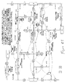
図1は、本発明によって制御することができる例示的な配電システムの一部分の簡略図である。配電システムは、従来の電線のような配電線106を通じて複数のユーザ104(例えば、工場、家庭など)に接続した複数の電源102を含む。配電線106は、線106に沿って所定のポイントに配置された複数のノード108を有する。図1の電源、ユーザ、電線、及びノードの数の描写は任意であり、これらの構成要素の各々は、所定の配電システムのいずれかにおいて異なる構成又は数にすることができる。
FIG. 1 is a simplified diagram of a portion of an exemplary power distribution system that can be controlled in accordance with the present invention. The power distribution system includes a plurality of
米国特許第6,018,449号、第6,111,735号、第6,243,244号、及び第6,347,027号に開示されたシステムは、主な配電線上のローカルな構成とそこで感知された条件とに基づいて意志決定を行うために十分に適切であるが、本発明は、特により大きな配電システムでの異常性に対して、最終顧客に対するサービスを再構成して復旧するために(回路再構成)、及び電源の過負荷を回避するようなシステムリソースを割り当てるために、すなわち、配電システムの適切な再構成可能性を向上させるために、より効率的で柔軟性のある対応をすることができる。例えば、システムリソースの適切な割り当てを要求して確立するために、他のノードに対するソースの割り当てデータ又はメッセージの各ノードとの通信において、リソースを通じて方法が提供される。好ましい構成では、より大きな配電システムで特に有効であるノードの「チーム」が、関連スイッチング制御装置を有する配電システムに形成され、様々なチームは、故障の条件と他の回路の異常に応答して、システムの最も効率的で迅速な再構成を「交渉」するか又は解決するために互いに通信する。このようにして、よりインテリジェントでローカルな意思決定とチーム間の調整を実行することができる。 The systems disclosed in US Pat. Nos. 6,018,449, 6,111,735, 6,243,244, and 6,347,027 have local configurations on the main distribution lines. Although adequate enough to make decisions based on the sensed conditions there, the present invention reconfigures and restores service to end customers, especially for anomalies in larger distribution systems. More efficient and flexible for (system reconfiguration) and to allocate system resources such as avoiding power overload, i.e. to improve the proper reconfigurability of the power distribution system Can respond. For example, a method is provided through resources in communication with each node for source allocation data or messages to other nodes to request and establish an appropriate allocation of system resources. In a preferred configuration, a “team” of nodes that is particularly effective in larger power distribution systems is formed in a power distribution system with an associated switching controller, and various teams are responsive to fault conditions and other circuit abnormalities. Communicate with each other to “negotiate” or resolve the most efficient and rapid reconfiguration of the system. In this way, more intelligent and local decisions and coordination between teams can be performed.
図2は、ノード200の例示的な実施形態を示すものである。配電線202は、スイッチ204を通過し、これは、その点で配電線を開閉するものである。本発明の他の実施形態では、スイッチ204は、電圧調整(電圧調整器)無効電力制御、(スイッチコンデンサバンク)、及び故障感知などの電力の感知、制御、又は調整機能を実行することができる他の装置で置換することができる。
本発明と矛盾せずに、ノード200は、顧客の負荷又は代替ソースをスイッチ間に置いて、2つ(二重)、3つ、又はそれ以上のスイッチを制御する種類とすることができることが認められるであろう。この場合、配電線202は、単一のノード200に制御されて個別に開閉することができる2つ又はそれ以上のスイッチ204を通過する。この状況では、ノード200は、通信の観点からは単一のノードであるが、本発明の電力システムと制御アルゴリズムの観点からは複数ノードである。この状況では、情報フローは不変であるが、通信段階は、単にバイパスされる。
FIG. 2 shows an exemplary embodiment of node 200.
Consistent with the present invention, node 200 may be of the type that controls two (dual), three, or more switches with a customer load or alternate source between the switches. Will be recognized. In this case, the
ノードコントローラ206は、配電スイッチ204を制御する。ノードコントローラ206は、制御コンピュータ208、ディスプレイ209、及び関連するメモリ210を含む。メモリ210は、感知された条件と他のノードからの通信情報に応じてノードを制御するプログラムを保存し、システムに関する情報を保存する。
本発明はまた、ノード200が保護(過電流保護/故障遮断)機能を有する時のチーム作動のための特徴を含むものである。配電スイッチ204が異なる作動機能を保持することができ、それが回路の再構成に介入するためにその機能を高めるか又は損なわせることがあることを当業者は認識するであろう。例えば、最も廉価なスイッチは、大きな電流を遮断することができず、電圧及び電流センサの両方と共に装備することはできない。ノード200は、高い遮断電流の下でスイッチが開かないようにプログラムする(分割スイッチ制御)ことができ、又は代替として「回路保護装置」(再閉路装置又はブレーカ)としてプログラムすることができることも当業者は認識するであろう。保護装置としてプログラムされた場合、火災、又は回路又はユーザ装置に対する損害を防ぐため、又は安全性の懸念から、スイッチは過電流の条件下(故障電流)で開くものである。
The
The present invention also includes features for team operation when the node 200 has a protection (overcurrent protection / fault interrupt) function. Those skilled in the art will recognize that the
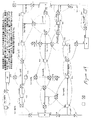
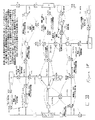
回路異常に応答してシステムを適切かつ最適に再構成してシステムリソースを割り当てるために通信上で搬送された情報を使用し、かつ情報の使用を調整する方法及び装置を、一般化されたアルゴリズム及び処理を含む様々な実施形態(一般的に図3−10、14、22、及び56−59を参照)において提供することが本発明の主要な態様である。このようにして、配電システム又は「チーム」の全体の保護及び再構成可能性が大幅に向上する。 A method and apparatus for using information carried over communications and coordinating the use of information to appropriately and optimally reconfigure a system in response to circuit anomalies and allocate system resources, and a generalized algorithm And providing in various embodiments including processing (generally see FIGS. 3-10, 14, 22, and 56-59) is a major aspect of the present invention. In this way, the overall protection and reconfigurability of the power distribution system or “team” is greatly improved.
制御コンピュータ208は、AC波形プロセッサ212に接続される。AC波形プロセッサ212は、フィールドインタフェースコネクタ214を通じて配電線202に接続される。これによって、電圧や電流などの配電線上の電気の様々な重要パラメータをプロセッサが測定し、それらをデジタル値に変換し、それらを制御コンピュータに送信し、処理し、通信し、メモリに記憶することができるようになる。
The
デジタルI/Oインタフェース216は、制御コンピュータ208、スイッチ204,及び配電線202に接続される。デジタルI/Oインタフェース216は、コンピュータコントローラ206にスイッチ位置感知情報と他の入力を受け取らせ、スイッチに制御出力を出力させる。
通信装置218は、制御コンピュータ208に接続され、制御コンピュータに図1の通信チャンネル110を通じてシステム上の他のノードと通信させる。通信装置は、都合良く利用可能で望ましい特性を有する任意の通信ネットワークと接続することができ、例えば、「Metricom Radio Radio」(今は「Schlumberger Industries」によって製造され、「Utilinet(登録商標)」製品ラインの下で販売されている)が1つの実施例で適切であることが見出されている。必要に応じて、本発明とは別の方法でシステムによって使用される第2の任意的な通信装置220をノード200に含むことができる。この例は「SCADA」ゲートウェイであろう。
The digital I / O interface 216 is connected to the
The
電源/バッテリバックアップ222を通じて、ノードに対して電力が供給される。バッテリは、太陽エネルギ、AC変圧器、又は電圧センサを通して電源から充電することができる。
ノードの各々は、通信チャンネル110に接続される。任意の種類の通信チャンネルを使用することができる。例えば、通信チャンネルは、ラジオ、インターネット、又は光ファイバケーブルとすることができるであろう。
Power is supplied to the node through the power supply /
Each of the nodes is connected to a
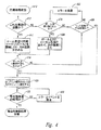
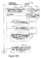
図3−8に関連して説明する本発明の第1の例示的な実施形態によれば、図3は、各ノードによって作動する同期カウンタの作動と状態選択処理を示す流れ図である。この処理では、ノードは、ノードを互いに同期させるために使用されるそのタイマとデータベースシーケンスカウンタを更新する。次に、ノードはエラー条件を検査し、エラーが見つかった場合はエラーフラッグを設定し、それらが同期、整合性検査、又は再構成イベントのどの状態に入るかをそれらのデータベースから判断する。同期処理に対する増強は、前の設定が適切であれば保護装置プロフィールの調整の前に回路の初期の修復を始めることができるように、再構成の前に装置の保護特性の「事前通告」を有する装置を提供するための段階315の追加である。
According to the first exemplary embodiment of the present invention described in connection with FIGS. 3-8, FIG. 3 is a flow diagram illustrating the operation of the synchronization counter operated by each node and the state selection process. In this process, the node updates its timer and database sequence counter that are used to synchronize the nodes with each other. The nodes then check for error conditions, set an error flag if errors are found, and determine from their databases whether they are in a synchronization, consistency check, or reconfiguration event state. An enhancement to the synchronization process provides a “pre-notification” of the protection characteristics of the device prior to reconfiguration so that an initial restoration of the circuit can be started before adjustment of the protection device profile if the previous settings are appropriate. Addition of
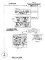
図4は、現在の好ましい実施形態に従って各ノードによって作動する同期処理状態の作動を示す流れ図である。この状態で、ノードは、配電システムに関する重要な制御情報のデータベースを構築する。全てのノードは、データベースの構築に貢献する。各ノードは、そのメモリにデータベースのコピーを保存する。現在の好ましい実施形態に従ってデータベースを構築する段階は、以下の通りである。各ノードは、前のノードからデータベースを受け取り、それ自体の情報の記録を追加し、そのデータベースを次のノードに渡す。この処理は、全てのノードが他の全てのノードから記録を受け取るまで続く。この処理が完了した状態で、次に、各ノードは、図5に示すように整合性検査状態に進む。 FIG. 4 is a flow diagram illustrating the operation of the synchronization process state operated by each node in accordance with the presently preferred embodiment. In this state, the node builds a database of important control information related to the power distribution system. All nodes contribute to database construction. Each node stores a copy of the database in its memory. The steps for building a database according to the presently preferred embodiment are as follows. Each node receives a database from the previous node, adds a record of its own information, and passes the database to the next node. This process continues until all nodes have received records from all other nodes. With this processing completed, each node then proceeds to the consistency check state as shown in FIG.
図5は、各ノードによって作動する整合性検査状態の処理の作動を例示する流れ図である。ノードがこの処理を作動させる時、それは、他の全てのノードから受け取った記録を検査し、記録がシステムの状態の適時なバージョンを反映することを保証するものである。
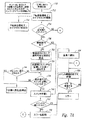
図6は、転送処理状態の作動を例示する流れ図である。この流れ図は、システム内の故障と続いて独立の区分化とが起きる時の各ノードによって使用される処理を説明する。この処理はまた、別のノードがこの処理を開始したというメッセージをノードが受け取る時にノード内で開始される。故障が起きた後でできるだけ多くのユーザに対して電力サービスを復旧するように関連するスイッチを閉にすることができるか否かを判断するために、各ノードは、この処理を使用することになる。これらの機能は、保護の設定が転送の要件に一致することを保証するために、転送論理の機能性を拡張するものである(段階645−654)。
FIG. 5 is a flow diagram illustrating the operation of the consistency check state process operated by each node. When a node activates this process, it examines records received from all other nodes and ensures that the records reflect a timely version of the system state.
FIG. 6 is a flowchart illustrating the operation of the transfer processing state. This flow diagram describes the process used by each node when a failure in the system and subsequent independent partitioning occurs. This process is also started in a node when the node receives a message that another node has started this process. Each node decides to use this process to determine whether the associated switch can be closed to restore power service to as many users as possible after a failure occurs. Become. These functions extend the functionality of the transfer logic to ensure that the protection settings match the transfer requirements (stages 645-654).
図7は、故障がクリアされた状態で、配電システムをその正常状態に戻すために各ノードによって使用される論理を説明する。これは、特に「閉鎖」移行が使用される時に、保護設定が「正常に戻す」移行の要件に一致することを保証するために、「正常に戻す」論理の機能性を拡張する(段階722及び750−752)。
図8は、図6の転送処理状態及び図7の正常に戻す処理状態中にこれらの処理のいずれかで要求される段階を完了するためにシステムが多くの時間を取らないことを保証するために使用されるタスクタイマの作動を示す流れ図である。これは、「正常に戻す」移行時、特に「閉鎖」移行の「正常に戻す」が使用される時に保護設定をリセットするために、「正常に戻す」論理の機能性を拡張する(段階830−831)。
FIG. 7 illustrates the logic used by each node to return the power distribution system to its normal state with the fault cleared. This extends the functionality of the “return to normal” logic to ensure that the protection settings meet the requirements of the “return normal” transition, especially when a “closed” transition is used (step 722). And 750-752).
8 ensures that the system does not take much time to complete the steps required in any of these processes during the transfer process state of FIG. 6 and the return to normal process state of FIG. It is a flowchart which shows the action | operation of the task timer used for. This extends the functionality of the “return to normal” logic to reset the protection settings during the “return to normal” transition, especially when the “closed” transition “return to normal” is used (step 830). −831).
この第1の例示的な実施形態に従って、ノードを制御するためにメモリ210はプログラムを保存し、システム内の各ノードのノード記録のデータベース(チームデータベース)を保存する。各記録は、多くのフィールドを含み、このフィールドは情報を含み、この情報により、ノードコントローラは、ノードスイッチを制御することができ、配電システムの要求に応答して配電線の特性を変えるものである。特定的な実施例では、記録は保護特性を含み、負荷移行/復旧中の保護設定の調整を容易にする。
In accordance with this first exemplary embodiment,
例示的な実施形態では、データベース内のノード記録の順序付けは、配電システム内のノードの物理的な順序付けに相当する。何らかの他の方法で順序付けされたデータベースのノード記録を保持し、配電システム内のノードの実際又は相対的な物理的位置の各ノード記録に情報を含むことは、本発明から逸脱しないと考えられる。ノードコントローラが二重又は多重スイッチタイプの場合には、各スイッチの位置は、データベース内に表示され、独立に順序付けすることができる。 In the exemplary embodiment, the ordering of the node records in the database corresponds to the physical ordering of the nodes in the power distribution system. Maintaining node records in the database in some other way and including information in each node record of the actual or relative physical location of the nodes in the power distribution system would not depart from the present invention. If the node controller is of the double or multiple switch type, the position of each switch is displayed in the database and can be ordered independently.
本発明の別の実施形態では、通信の観点から単一、二重、又は多重スイッチノードをチームの唯一のメンバーとして使用することができる。二重スイッチノードは、それが物理的に装備された唯一のメンバーである時(他のメンバーは後で装備されることがある)、チームの他のメンバーがチームから一時的に除外されていた時、又はチーム内の他のノードにあるエラーがチーム全体が故障条件に影響を与えることを回避する時に、チームの唯一のメンバーとして作用する。 In another embodiment of the present invention, a single, dual, or multiple switch node can be used as the only member of the team from a communication perspective. A dual switch node was temporarily excluded from the team when it was the only member physically equipped (other members may be equipped later) Acts as the only member of the team at times, or when an error at another node in the team prevents the entire team from affecting the fault condition.
また、本発明は、配電線に2つのソースがあり、2つのソースの間に通常は開のスイッチ(「タイ」スイッチ)がある図1のようなループ配電システムか又はソースが1つあり、タイスイッチがないラジアル配電システムの制御に適するものである。データベースがより簡単又はより複雑な配電システムトポロジーを表わし、本発明がそのようなトポロジーに対して作業することができることは、本発明から逸脱することにはならないと考えられる。 The present invention also has a loop power distribution system or one source as in FIG. 1 with two sources in the distribution line and a normally open switch (“tie” switch) between the two sources, It is suitable for control of radial power distribution systems without tie switches. It does not depart from the present invention that the database represents a simpler or more complex distribution system topology and that the present invention can work on such a topology.
特定的な実施例では、スイッチのどちら側が通電されていてどちら側が通電されていないかにより、タイスイッチは、いずれかの側から負荷を復旧(逆給電)するために閉じることができる。慣習的に、回路は、「右」側と「左」側を有するものとして、右側と左側の間のタイスイッチと共に説明される。最も小さい番号のノードは、回路の左側のソースに最も近いとして示され、最も大きい番号のノードは、回路の右側のソースに最も近いとして示される。2つの隣接する各ノード間を横断する回路は、「転送セグメント」又は「セグメント」と呼ばれる。 In a specific embodiment, depending on which side of the switch is energized and which side is not energized, the tie switch can be closed to restore the load (reverse power feed) from either side. Conventionally, a circuit is described with a tie switch between the right side and the left side as having a “right” side and a “left” side. The lowest numbered node is shown as closest to the source on the left side of the circuit, and the highest numbered node is shown as closest to the source on the right side of the circuit. A circuit that traverses between each two adjacent nodes is called a “transfer segment” or “segment”.
本発明の例示的な実施形態では、各ノードのデータベースは、(1)現在使用中の記録フラッグ、(2)各個別の記録によって表現された装置のタイプの表示、(3)ノードの通信アドレス、(4)その通常のスイッチの状態(開又は閉)、(5)現在のスイッチの状態、(6)電圧の状態(線に電圧が存在するか否か)(該当する場合は、位置により)、(7)故障の状態(故障が検出されたか否か)(該当する場合は、位置により)、(8)現在のタイムスタンプ、(9)データベースの連続番号、(10)論理処理の状態(どの状態と段階にスイッチがあるか)、(11)エラー条件ステータスフラッグ、(12)自動/手動作動モードステータス(該当する場合は、位置により)、(13)各位相上で感知された負荷の平均(該当する場合は、位置により)、(14)イベント処理開始時のタイムスタンプ、(15)正常に戻す方法の指示(開放又は閉鎖移行)、(16)ノードが回路の影響される部分内にあったか否かの指示、(17)左側から回路に電力供給した時に、現在の保護設定により適切に保護されるセグメントの最大数、(18)右側から回路に電力供給した時に同様に保護されるセグメントの数を含む。この例示的な実施形態の目的のために、セグメント(上の項目17と18を参照)は、図1の2つの隣接するチームのノード間の配電線を表すものである。二重又は多重スイッチを含む単一の通信ノードの場合、セグメントの数は、追加セグメントとして主配電線に沿った任意の2つのスイッチ位置の間の負荷の数になる。「セグメントの最大数」は、以下に概説される方法によって得られる。本発明の別の実施例では、本発明の範囲から逸脱することなく、各ノードのデータベースの記録に異なるノードデータを保存することができることが認められるであろう。
In an exemplary embodiment of the invention, each node's database includes (1) the currently used record flag, (2) an indication of the type of device represented by each individual record, and (3) the node's communication address. (4) its normal switch state (open or closed), (5) current switch state, (6) voltage state (whether or not voltage exists on the line) (if applicable, depending on position) ), (7) Failure status (whether or not a failure was detected) (depending on location, if applicable), (8) Current time stamp, (9) Database serial number, (10) Logic processing status (Which state and stage the switch is in), (11) error condition status flag, (12) automatic / manual operating mode status (depending on location, if applicable), (13) load sensed on each phase Average (applicable (Depending on the location), (14) Time stamp at the start of event processing, (15) Instruction on how to return to normal (open or closed transition), (16) Whether the node was in the affected part of the circuit (17) When the circuit is powered from the left side, the maximum number of segments that are properly protected by the current protection settings. (18) The number of segments that are similarly protected when the circuit is powered from the right side. Including. For purposes of this exemplary embodiment, the segment (see
チームのローカル記録データベース(上記)により、各ノードは、配電システムに関する十分な情報を保持することが可能になり、そのローカルスイッチをインテリジェントに制御する。更に、データベースは、ノードに局所的に保存されるので、ノードは、他のノードに情報を問い合わせる必要がなく、他のノードから作動命令を受け取るのを待つ必要もない。
本発明と矛盾することなく、現在使用フラッグになっている記録を用いて、調整されたシステム作動からノードを取り除くか又はノードに調整されたシステム作動を再開させることができる。ノードの作動を取り除くか又は再開するかの意思決定は、外部の意思決定実体又はノード自体によって行うことができるが、これに限定されることはない。
The team's local record database (above) allows each node to retain sufficient information about the power distribution system and intelligently controls its local switch. Furthermore, since the database is stored locally at the node, the node does not need to query other nodes for information and does not have to wait to receive an operational command from the other node.
Consistent with the present invention, a record that is currently in use can be used to remove a node from the coordinated system operation or to resume the coordinated system operation to the node. The decision to remove or resume operation of a node can be made by an external decision making entity or by the node itself, but is not limited to this.
保護プロフィールとチームデータベース
本発明は、保護装置プロフィール内に付加的な属性の表示を含むものである。これらの属性は、保護エンジニアの能力を向上させ、チームノードに対して意図された作動範囲又は設定の目的を伝達する。更に、これらの属性は、以下に明確に説明するように、個々の装置の保護設定に別に表示されない限り追加のチーム関連の機能性を支持するものである。属性は、以下の通りである。(1)「プロフィールタイプ」は、プロフィールの意図された使用法を指示する。好ましい実施例の場合、可能性のある値は、(a)ノードがそれらの正常な作動状態にある時に使用するための「チームモード/正常」であり、通常は開スイッチは開であり、他は全て閉である。好ましい実施形態では、複数のプロフィールを保持することは、この発明の範囲から逸脱することはないが、一年の季節又は負荷ベースの判断基準のような作動パラメータに基づいて動的に選択された1つだけの「チームモード/正常」プロフィールがある。(b)付加的なセグメント又は負荷がこの装置においてピックアップされるか又は担持される必要があり、正常プロフィールが不適切である状況で使用するための「チームモード/転送」。以下に説明する様々な判断基準に基づいて使用するために選択された複数の「チームモード/転送」プロフィールが存在することがある。(c)永続的なエラー又は問題のためにチーム作動が有効でないか又は一時的に無効な時(以下にこれらは「転送停止」条件と言及される)の「スタンドアローン」。(d)「正常に戻る」チーム作動(以下を参照)中に使用するための「チームモード/正常に戻る」。(2)「セグメントの数、左側の配電」は、ローカルスイッチの位置で開始する追加セグメントの最大数を指示し、これは、回路の左手側から電力が供給される時にプロフィールによって保護することができる。システムが回線の端末を保護するプロフィールを有する他の保護装置を含む場合、この数は、装置の直接及ぶ範囲よりも大きい値であると仮定することができる。この場合、他の装置がチームのメンバーである時には、本発明の特徴の1つは、プロフィール間の整合性を維持することである。(3)「セグメントの数、右側の配電」。電力が右側から供給される以外は上と同様である。(4)「最大負荷」は、プロフィールが保護するように意図した顧客負荷の最大量を指示する。この値は、一般的にユーザによって予め規定され、保護装置の故障解除が起きる可能性がある状況でプロフィールが使用されないことを保証するために実際の時間負荷データと比較される。(5)「保護選択キー」。プロフィールに関連する実際の構成設定に対する指標又は内部ポインタである。この指標により、装置に予め負荷されるか又は別のデータベースとして維持されるかのいずれかによってユーザ指定エントリが装置設定の集合に接続されるようになる。当業者は、保護装置設定の構成を特徴付けるために使用することができる他の属性と属性値を認めることができるであろう。
Protection Profile and Team Database The present invention includes the display of additional attributes within the protection device profile. These attributes improve the ability of the protection engineer and communicate the intended operating range or setting purpose to the team node. In addition, these attributes support additional team-related functionality, unless otherwise indicated in the individual device protection settings, as will be clearly described below. The attributes are as follows. (1) “Profile Type” indicates the intended usage of the profile. In the preferred embodiment, the possible values are (a) “team mode / normal” for use when nodes are in their normal operating state, normally open switch is open, others Are all closed. In a preferred embodiment, maintaining multiple profiles does not depart from the scope of the invention, but was selected dynamically based on operating parameters such as yearly seasons or load-based criteria. There is only one “Team Mode / Normal” profile. (B) “Team Mode / Transfer” for use in situations where additional segments or loads need to be picked up or carried on the device and the normal profile is inappropriate. There may be a plurality of “team mode / transfer” profiles selected for use based on various criteria described below. (C) “Stand-alone” when team operations are not valid or temporarily invalid due to permanent errors or problems (these are referred to below as “Transfer Stop” conditions). (D) “Team Mode / Return to Normal” for use during “Return to Normal” team operation (see below). (2) “Number of Segments, Left Power Distribution” indicates the maximum number of additional segments starting at the local switch position, which can be protected by the profile when power is supplied from the left hand side of the circuit. it can. If the system includes other protection devices with a profile that protects the terminals of the line, this number can be assumed to be a value greater than the direct range of the devices. In this case, when the other device is a member of a team, one of the features of the present invention is to maintain consistency between profiles. (3) “Number of segments, distribution on the right”. Same as above except that power is supplied from the right side. (4) “Maximum load” indicates the maximum amount of customer load that the profile intends to protect. This value is typically predefined by the user and is compared to actual time load data to ensure that the profile is not used in situations where a failure of the protective device may occur. (5) “Protection selection key”. An indicator or internal pointer to the actual configuration settings associated with the profile. This indicator allows user-specified entries to be connected to a set of device settings, either preloaded on the device or maintained as a separate database. One skilled in the art will recognize other attributes and attribute values that can be used to characterize the configuration of the protector settings.
他のチームメンバーの保護設定が、開スイッチを閉じることによって付加的な負荷がピックアップされる前に調節を要求するか否かを判断するのが本発明の目的である。すなわち、ローカル記録内の「セグメント数」フィールドは、局所的に判断され、チームメンバーの間で共有されるべきである。この処理は、正常の作動中に、チームのデータベースが交換される度に定期的に行われる(図3、段階315の「同期」処理)。以下に説明するが、エラー処理及び/又は転送イベント中のフィールドに対する値の判断には、更に複雑な処理が伴うものである。
It is an object of the present invention to determine whether the protection settings of other team members require adjustment before additional load is picked up by closing the open switch. That is, the “number of segments” field in the local record should be determined locally and shared among team members. This process is performed periodically each time the team database is exchanged during normal operation (FIG. 3,
「セグメントの数」フィールドの計算−正常作動
以下の説明は、転送以外の正常なチーム作動及び「正常に戻る」イベント又はエラー処理中に、現在アクティブなプロフィールに対して「セグメントの数」フィールドが計算される方法を特定するものである。従って、保護装置は、転送又は特定のエラー条件が存在しない限り、それらの作動プロフィールに対してチームが引き起こした変更なく作動する。アクティブなプロフィールに対する変更が行われ、季節の変化、負荷、又は他の感知又は伝達された情報に基づきチームを通して調節された場合には、それは、この発明の範囲又は意図から逸脱することはない。
チームデータベースのローカル記録内で装置の種類と機能に基づいて「セグメントの数」フィールドを導出するための可能な方法は多い。以下の例示的な方法は、スイッチと制御装置固有の機能に基づいている。
Calculation of the “Number of Segments” Field—Normal Operation The following description describes the number of segments field for the currently active profile during normal team operation other than transfer and “return to normal” events or error handling. It specifies the method to be calculated. Thus, the protection devices operate without changes caused by the team to their operating profiles, as long as there are no transfer or specific error conditions. If changes to the active profile are made and adjusted through the team based on seasonal changes, loads, or other sensed or communicated information, it does not depart from the scope or intent of this invention.
There are many possible ways to derive the “number of segments” field based on the device type and function in the local record of the team database. The following exemplary methods are based on switch and controller specific functions.
区分化スイッチ:初期化時に、保護される可能性があるセグメントの数は無限に大きな数に設定される。チームデータベース又はローカル記録が転送される時(同期の間又は転送イベントの間)、カウントは、区分化装置のソース側の最も近い隣接ノードによって1つずつ減らされ、保護されるセグメントの数まで減少する。例えば、第2のノードに相当するローカル記録に対して、電力が左側から配電される時(左側のセグメントカウント)、第1のノードがその負荷側の3つのセグメントを保護することができ、第2のノードが区分化スイッチの場合は、それは、その左側の配電セグメントカウントを2に設定する。電力が右から配電される時に第3のノードのローカル記録がその位置を超えた2つのセグメントを保護することができることを指示する場合、ノード2にある区分化スイッチは、その右側のセグメントカウントを1に設定する。最初のノード(左側の配電)と最後のノード(右側の配電)に対しては、それらがソース側のノードを持たないために、特別の処置が為されるべきである。ソース側のセグメントカウントを終端(好ましい代替のソース)ノードに伝達するために、例示的な実施形態では、次の3つの任意選択肢がサポートされる。すなわち、(a)ソース側の保護装置によって見られるように、回路の最悪の場合の負荷保護の考察に基づいて、カウントを予め判断(設定)することができ、(b)それは、任意の高い値に(不適切なセグメントカウントに基づく付加的な回路負荷の回避を無効にするように)予め判断することができ、または、(c)それは、ソース側の保護装置(以下に示すサイドラインのチームメンバーを参照されたい)から通信上で取得することができる。上述の処置はまた、端末のノードが区分化装置(以下を参照されたい)ではなく保護装置である時にも適用される。
Partitioning switch: At initialization, the number of segments that may be protected is set to an infinitely large number. When a team database or local record is transferred (during a synchronization or transfer event), the count is decremented by one by the nearest neighbor on the source side of the partitioning device and reduced to the number of protected segments To do. For example, for local records corresponding to the second node, when power is distributed from the left side (left segment count), the first node can protect the three segments on its load side, If the node of 2 is a partitioning switch, it sets the distribution segment count on its left side to 2. If the third node's local record can protect two segments beyond its location when power is distributed from the right, the partitioning switch at
保護装置(再閉塞器又はブレーカ):装置の保護設定と制御の強化に基づいてセグメントの数は設定することができ、又は以下に説明するように部分的にノードの機能に基づいて動的に計算される。
例示的な実施形態では、ブレーカ又は再閉塞器のアクティブなプロフィール属性は、ノードのローカル記録での「セグメントの数」フィールドの導出に使用される。セグメントの数は、ソース側の隣接ノード(マイナス1)によって保護されたセグメントの数か又はローカル装置のアクティブなプロフィール(現在使用されているプロフィール)に基づいて保護することができるセグメントの数の小さい方として計算される。後者の場合、チームのデータベースのチームのローカルコピーに保存された最新の負荷データは、プロフィールによって処理されたセグメントの数に相当する可能性のある計算された負荷(リアルタイムの負荷データに基づく)がプロフィールに対して設定された最大負荷を超えるか否かを判断するために使用される。それを行うと、プロフィールの「セグメントの数」は、負荷が処理することができる数まで減少する。この計算を行うための論理回路は、局所的に測定された負荷と、同様に現在の電流の流れる方向(左又は右)と、正常開スイッチの反対側の個々のセグメントの各々の現在測定された負荷とに対して敏感でなければならない。例えば、左側配電のセグメント数の計算の場合、カウントが正常開スイッチの位置を超えて保護を1セグメント拡張すると、正常開スイッチの右側に対するスイッチ位置で測定された回路の負荷は、プロフィールとの比較のために局所的に測定された負荷に加算されることになるであろう。特定プロフィールのノードを通して搬送される負荷電流の高い値を最終ユーザが任意に設定すると、負荷に基づくセグメントの減少を無効にすることができることを当業者は認めるであろう。
Protection device (recloser or breaker): The number of segments can be set based on device protection settings and enhanced control, or dynamically based in part on the function of the node as described below Calculated.
In the exemplary embodiment, the active profile attribute of the breaker or recloser is used to derive the “number of segments” field in the local record of the node. The number of segments is a small number of segments that can be protected based on the number of segments protected by adjacent nodes on the source side (minus one) or the active profile of the local device (the profile currently in use) Is calculated as In the latter case, the latest load data stored in the team's local copy of the team's database will have a calculated load (based on real-time load data) that may correspond to the number of segments processed by the profile. Used to determine whether the maximum load set for the profile is exceeded. When doing so, the “number of segments” of the profile is reduced to a number that the load can handle. The logic circuit for performing this calculation is the current measurement for each of the locally measured loads, as well as the current flow direction (left or right) and the individual segments on the opposite side of the normally open switch. Must be sensitive to the load. For example, in the calculation of the number of segments for the left power distribution, if the count exceeds the position of the normally open switch and the protection is extended by one segment, the circuit load measured at the switch position relative to the right side of the normally open switch is compared with the profile. Will be added to the locally measured load. Those skilled in the art will recognize that load reduction based segment reduction can be overridden if the end user arbitrarily sets the high value of load current carried through a particular profile node.
負荷転送又はエラー処理中のプロフィールの選択
この処理は、現在アクティブなプロフィールによって対処されるセグメントの数が、負荷転送、「正常に戻る」、又はエラー処理、又は復旧イベントの間に再計算される時にいつでも呼び出すことができる。これらのイベント中のチームデータベースに対する更新は、プロフィールの検索/選択処理をトリガする。以下に特定される処理は、適切なプロフィールを選択する簡略化された方法であるが、回線インピーダンス、回線負荷、又は他の要素に基づいてより手の込んだ処理を使用すること、又は異なるイベントに基づいて選択処理をトリガすることは、本発明の範囲から逸脱しないと考えられる。
Profile selection during load transfer or error handling This process recalculates the number of segments addressed by the currently active profile during a load transfer, "return to normal", or error handling, or recovery event It can be called at any time. Updates to the team database during these events trigger the profile search / selection process. The process specified below is a simplified method of selecting an appropriate profile, but using more elaborate processes based on line impedance, line load, or other factors, or different events It is believed that triggering the selection process based on does not depart from the scope of the present invention.
好ましい実施形態では、選択処理をトリガするイベントは以下の通りである。すなわち、(1)エラーと回路設定のその「正常」状態への移行なしで、全てのスイッチが正しい正常閉又は開位置での同期間隔の終了(以下を参照)。このイベントは、「チームモード/正常」プロフィールを選択させる。(2)チームの「停止転送」条件への移行であり、「スタンドアローン」プロフィールを選択させ、回路の最後の既知の構成が全てのスイッチが特定の「正常」位置にあったように仮定される(注、他のエラーは、現在アクティブなプロフィールの選択を変更しない)。(3)「正常に戻る」状態(以下を参照)への移行であり、「チームモード/正常に戻る」プロフィールを選択させる。(4)転送イベント(以下を参照)中の移行が進行中であることの検出であり、ローカルスイッチが処理すべきであるセグメントの最大数は、現在アクティブなプロフィールによって処理された数よりも大きい。 In the preferred embodiment, the events that trigger the selection process are: That is, (1) the end of the synchronization interval when all switches are in the correct normally closed or open position without the error and circuit setting transitioning to its “normal” state (see below). This event causes the “Team Mode / Normal” profile to be selected. (2) The transition to the team's “stop transfer” condition, which allows the “standalone” profile to be selected and the last known configuration of the circuit to be assumed that all switches were in a particular “normal” position. (Note, other errors do not change the selection of the currently active profile). (3) Transition to the “return to normal” state (see below), and select the “team mode / return to normal” profile. (4) Detection that a transition during a forwarding event (see below) is in progress, and the maximum number of segments that the local switch should process is greater than the number processed by the currently active profile .
この後者の状況において、例示的な実施形態では、ノードは、「チーム作動/転送」プロフィールのリストを通して走査し、セグメントの最大数と故障前の作動負荷を担持することができる第1の入力とを検索する。これによって、正常の転送の間に多くて一度だけプロフィールの再選択処理が行われる。プロフィールの選択が要求に対してより緊密に適合するように、故障位置に関して通知する処理中に追加情報を有するノードを提供することは、この発明の範囲を逸脱しないと考えられる。更に、選択処理(及び関連する通信)がセグメントのピックアップの度に実行されることは、本発明の範囲から逸脱しないと考えられる。
上述の選択処理が、実際の保護設定又は保護装置の作動モードの変更の必要性をもたらす場合には、変更が開始されて検証される。ポジティブな立証の後でのみ、チームのデータベースのローカル記録が更新される。立証が失敗した場合、エラー条件が生成され、論理回路が選択を再度試行する。転送が進行中の場合は、これは転送処理が満了になるまでいつまでも繰り返される。
In this latter situation, in an exemplary embodiment, the node scans through a list of “team activation / transfer” profiles and a first input that can carry the maximum number of segments and the operational load before the failure. Search for. Thus, the profile reselection process is performed at most once during normal transfer. Providing a node with additional information during the process of notifying about the fault location so that the selection of the profile more closely matches the requirements is considered not to depart from the scope of the present invention. Furthermore, it is believed that the selection process (and associated communication) being performed each time a segment is picked up does not depart from the scope of the present invention.
If the selection process described above results in the need to change the actual protection settings or the operating mode of the protective device, the change is initiated and verified. Only after positive verification is the local record in the team's database updated. If the verification fails, an error condition is generated and the logic circuit tries the selection again. If a transfer is in progress, this is repeated indefinitely until the transfer process expires.
自由継続カウンタ
図3の段階310から318は、特にノードが特定イベントが起きるのを待っている時にノードによって実行される他の処理の段階によって呼び出されることが多い同期ルーチンを含む。段階310では、ノードの自由継続の10番目のカウンタが増分される。自由継続カウンタは、タイムスタンプ理論の基準を確立するために使用される。図に簡単に示すように、これらのカウンタは、ノード間の同期を保証するために使用される。段階312でノードは、それが最大値に達したか否かを判断するために自由継続カウンタを検査する。最大値に達すると、同期間隔は満了する。同期間隔が満了した場合、次に段階314が実行され、ノードによって記録されたデータベースのシーケンス番号が増分され、ノードのデータベースにタイムスタンプが記録されて同期の保証を助ける。本発明によってもたらされる改善として、段階315で、例示的な実施形態はまた、上述の方法を使用して右側及び左側配電の両方の「セグメントの数」フィールドを計算/再計算する。データベースのシーケンス番号は、各同期間隔で1カウントずつ増加し、各ノードは、そのローカル記録にデータベースのシーケンス番号を含める。
Free
各ノードのデータベースのシーケンス番号は、全てのノードが適切に機能して同期する場合には、同一でなければならない。従って、各ノードのデータベースのシーケンス番号がその記録に含まれることにより、本発明のノードは、他のノードから受信したデータが適時で信頼することができるものであることを確実にする。このようにして、各ノードは、システムが全体として適切に機能しているか否かを自ら確かめることができる。 The sequence number of each node's database must be the same if all nodes function properly and synchronize. Thus, the sequence number of each node's database is included in the record, so that the node of the present invention ensures that the data received from other nodes is timely and reliable. In this way, each node can ascertain whether or not the system is functioning properly as a whole.
段階314の後に又は同期間隔が満了していない場合に、ノードは、通信が許可されているか否かを判断するために検査を行う。いくつかの状況では通信は妨げられることになる。例示的な実施形態において通信が許可されない時の例は、ノードのチームが最初に設定されていて、そのノードが設定情報を分配する時以外は他のノードは全てサイレントでなければならない時である。ノードに対して通信が許可されない場合、ノードは段階310に戻り、しばらくは独自で効力がある。
After
通信が許可されている場合は、段階320が実行される。ノードは、エラーとイベントを検査することになり、エラー又はイベントが検出されるとフラッグを設定する。次に、各ノードは、同期、整合性検査、又は再構成イベントの3つの状態のどこに入るかを判断する。各ノードは、3つの状態のどこに入るべきかを他のノードとは無関係に、それ自体の内部センサと他のノードから受け取ったデータベースの記録とに基づいてそれ自体で判断する。一般的に、システムが1つの状態から別の状態に移行している場合を除いて、全てのノードは、同じ状態にあることになる。しかし、任意の特定ノードは、一度に1つの状態になることができるのみである。
If communication is permitted,
同期処理状態
ノードが同期処理状態に入る場合、図4の流れ図によって例証される処理に続く。段階412で、ノードは、それが最初のアクティブなノードか否かを判断すべきである。本発明の例示的な実施形態では、いずれかのソースの直後のノードは、データベース内の最初のアクティブなノードとして設定することができ、他方のノードは、データベース内の最後のアクティブなノードになるであろう。その間のノードは、配電システム内のそれらの物理的順序付けを反映させるようにデータベース内に順序付けされると考えられる。また、データベース内に物理的順序付け以外で順序付けされたノードを保持し、ノードの絶対的又は相対的な物理的順序付けが判断されるように各ノードの記録内にデータを含むことは本発明から逸脱しないと考えられる。
If the synchronization processing state node enters the synchronization processing state, it follows the processing illustrated by the flowchart of FIG. In step 412, the node should determine whether it is the first active node. In an exemplary embodiment of the invention, the node immediately after either source can be set as the first active node in the database, and the other node becomes the last active node in the database. Will. The nodes in between are thought to be ordered in the database to reflect their physical ordering in the power distribution system. It is also a departure from the present invention to maintain nodes in the database other than physical ordering and to include data in each node's record so that the absolute or relative physical ordering of the nodes is determined. It is thought not to.
第1のノードは段階414に進み、ノードに関する記録のデータベースを構成する処理を開始する。第1のノードは、そのローカル記録をデータベース内に置き、次に、データベースをデータベースに列挙された次のノードに送る。このデータベースは、システムの周辺でノードからノードに送られるので「ボール」と呼ばれる。各ノードによってデータベースに追加された記録は、現在通過しているノードのために上記で列挙した18項目の情報を包含する。 The first node proceeds to step 414 and begins the process of constructing a database of records for the node. The first node places its local record in the database and then sends the database to the next node listed in the database. This database is called a “ball” because it is sent from node to node around the system. The record added to the database by each node contains the 18 items of information listed above for the currently passing node.
このデータベースを構築して通信することができる多くの実行可能な方法があるが、本発明の具体化では、ノードの記録をデータベースに追加させるために、次のノードの各々にそれを送ることによってデータベースを構築する。データベースは、本発明から逸脱することなく別の方法で構築することができる。例えば、各ノードは、他の全てのノードによる受信のために、その記録を通信チャンネル上で単に一斉送信することができる。 There are many feasible ways in which this database can be constructed and communicated, but in the embodiment of the invention, by sending it to each of the following nodes to have the node record added to the database: Build a database. The database can be constructed in other ways without departing from the invention. For example, each node can simply broadcast its record over the communication channel for reception by all other nodes.
第1のノードは、次に段階418に続き、ノードがまだボールを2度受け取っていないので段階420に続くことになる。段階420では、ノードは、そのリンクを実行する時か否かを判断する。ノードは別のノードに信号を発信し、その信号を送り戻すことによってそのリンクを実行する。これによってノードは、その通信システムが機能するか否かを判断することができる。そのリンクを実行する時か否かを判断するのに、ノードは、同期処理が所定の使用規定期間よりも長い時間を要したか否かを判断するために同期の時間間隔を検査する。これは、通信不良の時にノードがこの状態に膠着するのを回避するものである。
The first node then continues to step 418 and continues to step 420 because the node has not received the ball twice. In
リンクを実行する時でない場合、ノードは段階422に進む。この段階では、ノードは、図3の段階310から318までを実行し、エラーとイベントを検査する。エラー又はイベントが検出された場合はフラッグが設定され、必要に応じてアクティブな処理は終了する。これは、「同期及びエラー検査ループ」と呼ばれる。これが完了した状態で、ノードは、同期処理に戻って段階424に進み、それがボールを受け取ったか否かを判断するために検査する。同期処理が第1のノード以外のノードによって作動する場合には、それらは、段階412から直接段階424に進む。
If it is not time to perform the link, the node proceeds to step 422. At this stage, the node performs
段階424において、ノードがまだボールを受け取っていない場合には、それは段階420に戻り、リンクを実行するか又はボールが受け取られるまでこのサイクルを続けることになる。ボールが受け取られると、ノードは、次に段階424から段階426に進む。段階426では、ノードはボールを有するローカル記録を含み、ボールを次の装置に送る。(最後に列挙されたノードは、最初に列挙されたノードにボールを送ることになる。)ノードは段階418に進み、それがボールを2度受け取ったか否かを検査する。受け取っていない場合には、次に、ノードは再度段階420に行き、その中でループを続ける。
ボールが2度目に受け取られた時、ノードは、段階424から段階426、そして418、次に段階428に進み、通信リンクを試験するために別のノードに対するリンク実行メッセージを予定してそれが作動していることを保証する。これは、段階420でリンクカウンタを実行する時間が満了する場合にノードが移る段階と同じ段階である。
In
When the ball is received a second time, the node proceeds from
段階428でノードがその通信リンクを実行した後に、ノードは、段階430に進み、整合性検査カウンタを検査して図5の流れ図に示すように整合性検査状態に入る時間か否かを判断する。ノードが整合性検査状態に入る時間にまだなっていない場合には、ノードは、次に段階432を続けることになり、そこでそれは、同期及びエラー検査ループを実行することになる。次に、ノードは段階430のサイクルに戻り、それが整合性検査の時間になるまでこのループを続けることになる。
After the node performs its communication link at
本発明の例示的な実施形態では、同期処理は、所定の間隔につき一度行われる。所定の間隔の長さは、システム内のノードの数に基づいている。この間隔は、本発明から逸脱することなく、長い又は短いか、又はシステム内のノードの数以外の何かに基づく可能性があると考えられる。
従って、図4の流れ図によって例証された処理は、各ノードの情報を定期的に更新する。この処理により、各ノードは、他の全てのノードのステータスに関する最新の情報を包含することが可能となる。
In an exemplary embodiment of the invention, the synchronization process is performed once every predetermined interval. The length of the predetermined interval is based on the number of nodes in the system. It is contemplated that this interval may be based on something other than the number of nodes in the system, either long or short, without departing from the invention.
Therefore, the process illustrated by the flowchart of FIG. 4 periodically updates the information of each node. By this processing, each node can include the latest information regarding the statuses of all other nodes.
整合性検査状態
図5は、整合性検査状態のために使用される処理を表す流れ図を示すものである。この状態では、各ノードは、そのメモリに含まれるデータベース記録が同期されるように見えること、エラーの状態がないこと、及びノードが正しい状態にあることを保証するために検査する。段階512では、ノードは、データベースのシーケンス番号をそれらが全て一致することを保証するために検査する。このようにして、各ノードからのデータベースの記録が全て同じ同期処理からであることをノードは保証することができる。
Consistency Check State FIG. 5 shows a flowchart representing the process used for the consistency check state. In this state, each node checks to ensure that the database records contained in its memory appear to be synchronized, that there is no error condition, and that the node is in the correct state. In
シーケンス番号が一致しない場合、ノードは次に段階514に進み、シーケンス番号のためにフラッグが設定され、それらを再同期するように再構成される。このエラーフラッグは、別の同期間隔が起きてデータベースのシーケンス番号が一致するまでは、全ての協調したチーム活動が起きるのを回避することになる。
シーケンス番号が一致する場合又は段階514でフラッグが設定された後は、ノードは、次に段階516まで続く。この段階では、ノードは、データベース記録をそれぞれ検査し、それら全てが互いに1秒以内にタイムスタンプされることを保証する。この要件は、データベース内の記録が約一時点のシステムの実態を正確に反映することを保証するものである。記録が互いに1秒以内にタイムスタンプされない場合、ノードは段階518に進み、新しいタイムスタンプのためのフラッグを設定する。このフラッグは、互いにタイムスタンプが同期されていない場合に、ユーザによって設定された所定量を超えるだけの同期されたチーム活動を許可しないことになる。一実施形態では、タイムスタンプが5秒同期を外れる場合は、エラーフラッグが設定される。許容可能なタイムスタンプの不一致は、実施に依存するパラメータであることが認められるであろう。
If the sequence numbers do not match, the node then proceeds to step 514 where flags are set for the sequence numbers and reconfigured to resynchronize them. This error flag will prevent all coordinated team activity from occurring until another synchronization interval occurs and the database sequence numbers match.
If the sequence numbers match or after the flag is set in
本発明の例示的な実施形態では、整合性検査の厳密な実行は「安全モード」と見なすことができると考えられる。本発明と矛盾せずに他のモードが存在することができ、様々なレベルの整合性検査エラーがあっても、このモードはチーム活動の連続作動を可能にすると考えられることが認められるであろう。
タイムスタンプが同期を外れているとしてフラッグ設定されていないか、又はフラッグが段階518で設定された後に、ノードは、次に段階520に進む。この段階では、ノードは転送停止エラーを検査し、もし何らかのエラーがあれば、エラーをクリアすることができるか否かを判断しようと試みる。エラーの例として次のようなものがある。すなわち、(1)ノードのデータベースシーケンス番号が一致しない、同期を外れるエラー、及び(2)誤作動スイッチなどの外部条件のために発生し、完全に終了できなかった再構成処理である。
In an exemplary embodiment of the invention, it is believed that the strict execution of the consistency check can be considered a “safe mode”. It will be appreciated that other modes may exist consistent with the present invention and that even with various levels of consistency check errors, this mode is considered to allow continuous operation of team activities. Let's go.
After the time stamp is not flagged as out of sync, or the flag is set at
エラーをクリアすることができる場合は、段階522でクリアされるべきエラーのフラッグが設定される。ノードは、次に段階524を続行する。この段階では、ノードは、転送のための準備が全て完了しているか否かを判断する。再構成イベントの後で、ノードは、全てのノードが同期されており、他の必要なノードが一致することを確かめなければならない。例えば、一実施形態では、ノードはそのデータベースを検査し、全てのノードが所定のユーザが規定した限度内の平均的な3相負荷を有するか否かを判断する。転送の準備が全て完了していることをノードが判断すると、それは、次に段階526に進み、転送の準備が全て完了していることを指示するフラッグを設定する。
If the error can be cleared, an error flag to be cleared is set in
次に、ノードは段階528に進み、正しい準備完了の状態にあるか否かを検査する。各ノードは、転送処理のための準備が完了しているか又は正常処理に戻るための準備が完了しているかのいずれかであり、全てのノードは同じ準備完了状態にあるべきである。この段階では、ノードは、そのローカル情報と、データベースの情報に基づいて他のノードが入っている状態とに基づいて、どちらの準備完了の状態にそれが入るべきであると考えられるかを比較することになる。ノードが正しい準備完了状態にない場合、それは段階530に進み、正しい準備完了状態を判断してそれに変更する。 The node then proceeds to step 528 and checks whether it is in the correct ready state. Each node is either ready for transfer processing or is ready to return to normal processing and all nodes should be in the same ready state. At this stage, the node compares to which ready state it should be based, based on its local information and the status of other nodes based on information in the database. Will do. If the node is not in the correct ready state, it proceeds to step 530 to determine and change to the correct ready state.
ノードは、次に段階532に進み、そこで「正常に戻る」モードの不一致があるか否かを判断するために検査を行う。この段階で、ノードは、全てのノードが同じ「正常に戻る」モード、開放移行、閉鎖移行、又は無効にされた機能に設定されていることを確実にするために検査を行う。全てのノードが同じ「正常に戻る」モードに設定されていない場合には、不一致があり、段階534でエラーフラッグが設定される。次に、ノードは図3の段階310に戻る。
The node then proceeds to step 532 where it checks to determine if there is a “return to normal” mode mismatch. At this stage, the node checks to ensure that all nodes are set to the same “return to normal” mode, open transition, closed transition, or disabled function. If all nodes are not set to the same “return to normal” mode, there is a mismatch and an error flag is set at
転送処理状態
図6の転送処理状態の流れ図は、単純な例の助けを借りて以下に説明される。図1を参照して、ノード108Aと108Bの間の配電線106で故障が生じると仮定する。上述のように典型的な配電システムは、安全と回路保護のために、電源にブレーカ又は再閉塞器(再閉塞ブレーカ)のいずれかを有することになる。米国特許第6,018,449号に開示されたシステムを使用して、区分化装置は、図1に示すようにスイッチの位置108A−Fに配置することができる。本明細書に説明する「区分化装置」は、「EnergyLine Model 2801」に基づいており、付加的な特性が追加されて本発明の例示的な実施形態の下での作動を支持するものである。標準的な区分化装置の論理回路は、次の場合にスイッチを開にする(トリップする)ことになる。すなわち、1)その区分化論理回路が有効であり、装置が作動する場合、2)全ての検出された相の電圧降下の予め設定された数(一般的に1−3)が短時間(一般的に、45秒)内に数えられた場合、3)第1の電圧損失の前に過電流状態が検出された場合、及び4)スイッチが現在閉の場合である。従来のソフトウエアの付加的な任意選択肢は、3相全てで感知された電圧が大きく不均衡になり、設定された時間間隔の間(一般的に30秒間)連続して不均衡が続いた場合、スイッチのトリップを可能にする。
本発明と矛盾することなく、ここで説明した「区分化装置」は、以下に限定されるものではないが、本発明の意図から逸脱しない多重スイッチオペレータ、故障中断スイッチ、及び気中遮断スイッチを含む多くの形式の1つにすることができることが認められるであろう。この例のために、ここで説明した単一のスイッチ区分化装置が使用されることになる。
Transfer Processing State The transfer processing state flow diagram of FIG. 6 is described below with the help of a simple example. Referring to FIG. 1, assume that a failure occurs in distribution line 106 between
Consistent with the present invention, the “partitioning device” described here is not limited to the following, but includes a multiple switch operator, a failure interrupt switch, and an air cut-off switch that do not depart from the intent of the present invention. It will be appreciated that one of many forms can be included. For this example, the single switch partitioning device described here will be used.
本発明の例示的な実施形態で提供される可能性がある任意的な機能は、電圧降下のすぐ前に故障が検出されなかった場合でも、電圧降下の設定されたカウントに関してスイッチを開にするものである。これによって、他の装置と通信せずに回線故障部分の両側を分離する第1段階のすぐの実行が可能になる。別の任意的な機能は、電圧降下(検出された故障に続いて)に対する設定されたカウントを現在指定された開のタイスイッチに対するスイッチの位置に基づいて局所的に動的に計算させるものである。設定パラメータにより、この動的に計算された範囲のカウントは、常に最大と最小の番号の間に入るようにユーザによって更に制約される。別の任意選択肢により、単一の拡張電圧降下の後でスイッチが開くことが可能になる。最終的に電圧降下の後の故障のカウントは、各イベントを次のいずれかの故障として数えるように設定することができる。すなわち、1)最初の電圧降下が故障によって先行された場合、又は2)全ての電圧降下が故障によって先行された場合である。 An optional function that may be provided in an exemplary embodiment of the present invention is to open the switch for a set count of voltage drops even if no fault is detected immediately before the voltage drop. Is. This allows for immediate execution of the first stage of separating both sides of the line failure part without communicating with other devices. Another optional feature is to have the set count for voltage drop (following detected fault) dynamically calculated locally based on the position of the switch relative to the currently specified open tie switch. is there. With the configuration parameter, this dynamically calculated range count is further constrained by the user to always fall between the maximum and minimum numbers. Another option allows the switch to open after a single extended voltage drop. Eventually, the fault count after the voltage drop can be set to count each event as one of the following faults. 1) when the first voltage drop is preceded by a fault or 2) when all voltage drops are preceded by a fault.
本発明の例示的実施形態の別の独特な機能は、その修正された「単発式ロックアウト」機能である。何らかの自動作動の一部としてスイッチが閉じられた(又は、人間の作動によって手動で閉じられた)場合、「EnergyLine Model 2801−SC」を含むいくつかの区分化装置は、作動に続いて短い時間間隔の間(正常は5秒間)に電圧降下が検出された場合に、スイッチを自動的に再び開にするように設定することができる。本発明の例示的な実施形態は、2つのカウントの電圧降下が検出されるまで、スイッチを開にするのを回避する別の機能を有する。これは、回路のブレーカの再び閉じるパターンが、故障による瞬時の閉作動と続いてトリップ作動とを含む時に恩典をもたらすものである。 Another unique feature of the exemplary embodiment of the present invention is its modified “single lockout” feature. If the switch is closed (or manually closed by human activation) as part of some automatic activation, some segmentation devices, including “EnergyLine Model 2801-SC”, will be in a short time following activation. The switch can be set to automatically reopen if a voltage drop is detected during the interval (normally 5 seconds). The exemplary embodiment of the present invention has another function that avoids opening the switch until a voltage drop of two counts is detected. This is advantageous when the circuit breaker's reclosing pattern includes an instantaneous closing action due to a failure followed by a trip action.
各スイッチの位置での自動回路区分化装置の使用と矛盾することなく、故障をクリアする負荷がかかった時にスイッチが1回又はそれ以上開く/作動するような再閉塞器で置き換えることができることを当業者は認識するであろう。チームの協調機能を支持するために、これは、予めパッケージ化された市販の再閉塞器製品に対して修正を必要とすることになるが、区分化装置によって提供されるのと類似の機能性を達成することができる。区分化装置の実装で実現された「単発式ロックアウト」機能の変形は、多くの再閉塞器で「ブロック再閉塞」任意選択肢として使用することができることも注意されるべきである。導入において示したように、再閉塞器の代わりに区分化装置を使用する手法の困難な点は、不適切な装置の過度のスイッチング又はトリップ/ロックアウトを回避するためにこれらの再閉塞器の保護設定を調整することである。この可能性を最小にするか又は除去するための手段を提供するのが本発明の目的である。図1の配電システムが自動区分化装置を含む場合、自動配電回路106上のノード108Aと108Bの間で故障が発生した後に、装置は、設定次第でスイッチをノード108A、108B、108Cの任意の1つ又は全てのノードで開にして、開スイッチから下流にある全てのユーザ104A、104B、104Cへの供給を止めさせるものである。
Without being inconsistent with the use of an automatic circuit partitioning device at each switch position, it can be replaced by a recloser that opens / activates the switch one or more times when loaded to clear the fault. Those skilled in the art will recognize. In order to support the team's collaborative capabilities, this will require modifications to pre-packaged commercial reocclusion products, but functionality similar to that provided by the segmentation device. Can be achieved. It should also be noted that a variation of the “single lockout” function realized with the implementation of the segmentation device can be used as a “block re-occlusion” option with many re-occlusion devices. As indicated in the introduction, the difficulty of using a segmentation device instead of a reocclusion device is that the reocclusion of these reocclusion devices is avoided to avoid undue switching or trip / lockout of the improper device. It is to adjust the protection settings. It is an object of the present invention to provide a means for minimizing or eliminating this possibility. If the power distribution system of FIG. 1 includes an automatic partitioning device, after a failure occurs between
本発明の1つの実施例では、区分化論理回路は、故障及び正常開タイスイッチ108G間の全てのスイッチを開にするように設定されることになる。これによって、本発明の本実施形態は、スイッチを一度に再び閉にすることができるようになり、配電システムによって認識される負荷を少しずつ増加させてユーザに対するサービスを復旧させるシステムを助けるものである。任意のノードが区分化を完了した状態で、ノードは、図6の流れ図に示されている転送処理状態に入り、そこでノードは、そのスイッチを閉にしようと試みることになる。ノードはまた、別のノード又はノードのチームが転送処理に入ったという通信を受け取ると、転送処理に入ることになる。 In one embodiment of the invention, the segmentation logic will be set to open all switches between the fault and normally open tie switch 108G. Thus, this embodiment of the present invention allows the switch to be closed again at once and helps the system to restore service to the user by gradually increasing the load recognized by the power distribution system. is there. With any node completing the partitioning, the node enters the transfer processing state shown in the flow diagram of FIG. 6, where the node will attempt to close its switch. A node will also enter the forwarding process when it receives a communication that another node or team of nodes has entered the forwarding process.
本発明から逸脱することなく、区分化を完了する以外のイベントによって転送処理状態を開始することができる。配電システムのタイプとその必要性及び特性に依存して、他のイベントにシステムをトリガさせてアクションをもたらすことが望ましいことがある。例えば、深刻な過小又は過度の電圧条件の検出によりシステムがトリガされてアクションに入ることが望ましいであろう。
各ノードは、その独自のステータス情報に関連するそのデータベースの記録を絶えず更新している。従って、他の全てのノードに関連するデータベースの記録、すなわちボールは、同期処理状態でのみ各ノード送られるが、各ノードは、それ自体のステータスで更新記録を維持する。
この例の目的のために、区分化によりノード108A、108B、及び108Cのスイッチが開になり、結果的にユーザ104A、104B、及び104C全てに対する供給が止められたものと仮定する。区分化が完了した状態で、3つのノード108A、108B、及び108Cは、それぞれがスタンドアローンの区分化を受けたために、転送処理状態をそれぞれ別々に開始することになる。
The transfer processing state can be initiated by an event other than completing the segmentation without departing from the invention. Depending on the type of power distribution system and its needs and characteristics, it may be desirable to trigger other systems to trigger actions. For example, it may be desirable for the system to be triggered to enter an action upon detection of a severe under or over voltage condition.
Each node continually updates its database record associated with its own status information. Thus, the database records associated with all other nodes, i.e., balls, are sent to each node only in a synchronous processing state, but each node maintains an update record with its own status.
For the purposes of this example, assume that partitioning opened the switches of
ノードが図6の流れ図に示す転送処理状態に入る時、ノードは、段階612を実行して処理終了タイマタスクを開始する。このタイマは、ノードがタスクを完了させようとして必要以上に長く費やさないことを保証する。仮にノードが割り当てられた時間内に作業を完了させることを何かが妨げた場合、タイマは、転送処理状態を終了させることになる。各ノードは、転送処理を最初に開始したノードと同じ開始時間をそのタイマに対して使用することになる。このようにして、転送処理内の全てのノードは、同じ時間に「満了」することになる。このタイマの作動とそれが呼び出すタスクは図8に示されており、以下に説明する通りである。
When the node enters the transfer processing state shown in the flow chart of FIG. 6, the node executes
タイマの長さは、制御されている特定システムの必要性を満足するようにシステムオペレータが設定することができる。例えば、故障が起きた後に電力ラインで作業している修理作業員の安全を保証するために、故障が発生した後の所定の時間の間、タイマは、ノードを転送処理から取り除くように設定することができる。従って、転送処理状態の条件が満たされ、それがスイッチを閉にして電力ラインに通電していたとしても、転送処理は満了になっており、スイッチが閉にならないために、システムのサービスを始めた修理作業員が危険に曝されることはない。
本発明の例示的な実施形態では、これら3つのノードの各々は、それ自体の論理回路、保存されたデータ、及びセンサの読みにトリガされてそれら自体の転送処理に入る。本発明の現時点での例証的な実施形態は、この状態に入るノードのいずれに対しても中央制御、通信、又は承認を必要としない。
The length of the timer can be set by the system operator to meet the needs of the particular system being controlled. For example, to ensure the safety of repair workers working on power lines after a failure occurs, the timer is set to remove the node from the forwarding process for a predetermined time after the failure occurs be able to. Therefore, even if the transfer process condition is met and it is closed and the power line is energized, the transfer process has expired and the switch will not be closed. Repair workers are not at risk.
In the exemplary embodiment of the invention, each of these three nodes is triggered by its own logic, stored data, and sensor readings to enter its own transfer process. Presently illustrative embodiments of the present invention do not require central control, communication, or authorization for any of the nodes entering this state.
タイマが始動した状態で、ノードは段階616に進み、配電ネットワークの正常作動中に制御しているスイッチを閉じるか否かを判断する。図1を参照すると、スイッチ108A、108B、108C、108D、108E、及び108Fは、配電システムの正常作動中に閉じており、スイッチ108G、すなわちタイスイッチは、配電システムの正常作動中に開いている。スイッチ108A、108B、及び108Cは、それぞれ、システムの作動中に正常閉であるから、これらのノードは段階618に続くことになる。段階618では、既に転送処理状態に入っていた各ノードは、その更新された記録をデータベースに列挙された次のアクティブなノードと、データベースに列挙された前のアクティブなノードとに転送することになる。これら2つのノードは「最近隣」ノードと呼ばれる。ノード108Aはノード108Bに伝わり、ノード108Bは、ノード108Aとノード108Cに伝わり、ノード108Cは、ノード108Bとノード108Gに伝わることになる。従って、既に転送処理状態に入ったスイッチは、それぞれ、その進展をその最近隣に通知することになる。例示的な実施形態は「最も近い」近隣間の通信を使用するが、別の実施形態では、本発明と矛盾せずに別のノード対ノード通信パターンを使用することができることが認められるであろう。従って、本発明の例示的な実施形態に従って、各ノードは、配電システムの物理的レイアウトやノードの物理的配備に関係なく、その状態を他のノードに通知することができる。
With the timer started, the node proceeds to step 616 to determine whether to close the controlling switch during normal operation of the distribution network. Referring to FIG. 1, switches 108A, 108B, 108C, 108D, 108E, and 108F are closed during normal operation of the power distribution system, and switch 108G, or tie switch, is open during normal operation of the power distribution system. . Since
ノードが複数スイッチノードの場合、転送処理だけの目的のために、「最近隣」は、ノード自体の範囲内の1つのスイッチ位置でもよいことが認められるであろう。本発明の例示的な実施形態では、最近隣のデータベースは、内部チームのデータベースに含まれる情報から集められる。次に、転送論理は、最近隣のデータベースの情報を使用して実行される。ノードが複数スイッチノードの場合、各スイッチ位置に対して別の最近隣データベースが構築されることになる。この実施例では、最近隣のデータベースは、ローカルノードとそれに物理的に隣接する2つのノードからの情報から成るものである。 It will be appreciated that if the node is a multi-switch node, for the purposes of forwarding processing only, the “nearest neighbor” may be one switch position within the node itself. In an exemplary embodiment of the invention, the nearest neighbor database is gathered from information contained in the internal team database. The transfer logic is then performed using the information in the nearest database. If the node is a multiple switch node, a separate nearest neighbor database will be constructed for each switch location. In this embodiment, the nearest neighbor database consists of information from the local node and two nodes physically adjacent to it.
ノード108Gがノード108Cから通信を受け取ると、ノード108Gは、転送処理状態を開始する。一般的に、1つのノードが別のノードから他のノードが転送処理状態に入ったという通信を受け取ると、通信を受けるノード自体が転送処理状態に入ることになる。この手順により、システムが自己編成することができるようになり、最終的に中央事務所からの通信や人間との対話を何も要求せずにシステムの各ノードを転送処理状態にする。 When the node 108G receives the communication from the node 108C, the node 108G starts the transfer processing state. In general, when one node receives communication from another node that another node has entered the transfer processing state, the node that receives the communication itself enters the transfer processing state. This procedure allows the system to self-organize and ultimately puts each node of the system into a transfer process state without requiring any communication from the central office or human interaction.
すなわち、例示的な実施形態では、各ノードが処理の所定のポイントで行うのにどのアクションが適切かを判断するための集中制御又は論理センターは何も必要ない。本発明の各ノードは、そのセンサと通信した情報だけに基づいて作動することが可能である。この単純な作動構造のために、本発明のプログラムや論理を変える必要なく単にデータベースにノードを記録することにより、本発明は、容易に拡張又は再構成することができる。例えば、図1のノード108Bと108Cの間に新しいノードを追加するために、システムオペレータは、システムの適切な位置に新しいノードを物理的に挿入し、それをノード108Bと108Cの間のデータベースにプログラムするであろう。これは、ノード108Bが1スペース下がり、データベースのこの新しく作り出されたスペースに新しいノードの記録を挿入した後に、データベースの全てのノードの記録を移動させることによって達成される。 That is, in the exemplary embodiment, no centralized control or logical center is needed to determine which action is appropriate for each node to take at a given point in the process. Each node of the present invention can operate based solely on information communicated with its sensors. Because of this simple operating structure, the present invention can be easily extended or reconfigured by simply recording the nodes in the database without having to change the program or logic of the present invention. For example, to add a new node between nodes 108B and 108C in FIG. 1, the system operator physically inserts the new node at the appropriate location in the system and places it in the database between nodes 108B and 108C. Will program. This is accomplished by moving the records of all nodes in the database after node 108B has moved down one space and inserted a new node record into this newly created space in the database.
ノード108Gは、段階612を実行し、転送処理終了タイマを開始し、転送処理を開始したノードと同時にそれを終了するように設定し、次に段階616に進む。ノード108Gは、正常開スイッチを制御するので、それは段階638に進むことになる。段階638では、ノード108Gは、そのセンサ、そのデータベースの情報、及びノード108Cによってそれに送られた情報を観察することになり、それが閉にすることができるか否かを判断する。本発明の例示的な実施形態では、それが閉にすることができるか否かを判断するために、表1に列挙された条件がノードによって検査される。表1の段階4で使用される条件は、表2に示されている。本発明から逸脱することなく、他の条件設定を使用することができる。
Node 108G executes
表1
ノードに関連する正常開スイッチを閉にするために、1つの有効な閉じたスイッチと1つの有効な開いたスイッチとは、正常開スイッチのいずれかの側に隣接するノードに関連して隣接するスイッチとして検出されるべきである。以下の規則は、隣接するスイッチの状態を有効にするために、正常開スイッチに関して満足すべきである条件を規定するものである。
故障回線部分の負荷側の正常開スイッチは、負荷を修復するために以下の場合に閉にすることができる。
1.エラー条件が存在しない。
2.隣接する故障側のスイッチが開である。
3.隣接する故障側のスイッチは故障を検出しなかったが、電圧降下を認識した。
4.停電前に隣接する故障側のスイッチによって認識された電流レベルは、ローカルスイッチで設定された限度内である(この段階で使用される条件は、表2に示されている)。
5.隣接する非故障側スイッチは、それが電圧降下及び/又は故障を観察したがそれが現在閉じていることを指示し、又は隣接する非故障側スイッチは、正常開スイッチであり、又は隣接する非故障側スイッチはブレーカであり、電圧は既に復旧されている(ローカルスイッチが正常開スイッチであり、代替給電装置にチームの再閉塞器が存在せず、及び電圧検査が不能な場合、この段階はバイパスされる)。
6.ピックアップすることができる「セグメントの数」はゼロよりも大きい。この試験の場合、供給の非故障方向(左又は右)に相当するチームデータベースのローカル記録からの数が使用される。
7.その電圧センサでは良好な電圧が検出される(この試験は、ユーザが設定することができる任意選択肢である)。
8.隣接するスイッチは、適正な論理作動段階にある。
Table 1
In order to close the normally open switch associated with the node, one valid closed switch and one valid open switch are adjacent in relation to the adjacent node on either side of the normally open switch. Should be detected as a switch. The following rules specify the conditions that should be satisfied for a normally open switch in order for the state of an adjacent switch to be valid.
The normally open switch on the load side of the failed line portion can be closed in the following cases to repair the load:
1. There is no error condition.
2. The adjacent fault side switch is open.
3. The adjacent fault side switch did not detect a fault but recognized a voltage drop.
4). The current level recognized by the adjacent failed switch before the power failure is within the limits set by the local switch (the conditions used at this stage are shown in Table 2).
5. An adjacent non-failure side switch indicates that it has observed a voltage drop and / or failure but is currently closed, or an adjacent non-failure side switch is a normally open switch, or an adjacent non-failure switch The failure side switch is a breaker and the voltage is already restored (if the local switch is a normally open switch, there is no team recloser in the alternative power supply, and the voltage check is not possible, this stage is Bypassed).
6). The “number of segments” that can be picked up is greater than zero. For this test, the number from the local record in the team database corresponding to the non-failing direction of supply (left or right) is used.
7). The voltage sensor detects a good voltage (this test is an option that the user can set).
8). The adjacent switch is in the proper logic operation stage.
表2
(この表は、表1及び3の段階4を補足説明する。)
転送処理中に負荷を復旧することができるか否かを判断するために、処理は、代替回路の容量と比較して転送される全負荷を使用する。
転送される負荷を制限するために、3つの基本的な設定値がエンジニアによって使用される。それらは次の通りである。
転送に対する容量(全給電装置負荷は適用不能)
転送のための最大容量
最大公称給電装置容量
3つの設定値は、全て左側の給電装置と右側の給電装置のための設定値を有する。3つの設定値の全ては、夏と夏でない季節の設定値も有する。
転送処理は、可能であれば、関連する給電装置上のリアルタイムの全負荷を使用する。このリアルタイムの全負荷の値は、変電所のRTUなどの任意のソースからの通信上で到達する。
この処理と共に作動する2つの設定値は、「転送に対する最大容量」と「最大公称給電装置容量」である。「転送に対する最大容量」は、その給電装置の負荷が軽い時に代替給電装置に転送することができるように設定された負荷の量である。「最大公称給電装置容量」は、実際のリアルタイム負荷と組み合わせて使用される。これら2つの差は、代替給電装置が処理することのできる現在のリアルタイム容量である。転送を行うために、次の開スイッチによって再構成イベントが始まる前に報告された負荷は、現在のリアルタイムの容量及び「転送のための最大容量」の両方よりも小さくなければならない。
リアルタイムの負荷は、少なくとも20分に一度はスイッチ制御装置に送られるべきである。リアルタイム負荷を最後に受け取って20分過ぎた後に、この値は不定になる。不定値は、フォールバック処理の影響を発生させる。これによって、このデータのソースがその報告に失敗した時の古い負荷データの転送が回避される。
フォールバック処理は、「転送のための容量(全給電装置負荷は適用不能)」を使用する。この値は、控えめな値になる傾向がある。この値を設定する時、エンジニアは、代替給電装置上の平均負荷、ピーク負荷、及び非常用負荷の容量を考慮すべきである。この量の負荷の転送をいつでも行うことができ、依然として代替給電装置によって対応されることをエンジニアは快適に感じるはずである。
2つの給電装置のための処理は別であることに注意されたい。1つの給電装置に対してリアルタイムの負荷データを提供することができ、一方、他の給電装置は、保守的な転送処理を使用する。
Table 2
(This table supplements
In order to determine whether the load can be restored during the transfer process, the process uses the total load transferred compared to the capacity of the alternative circuit.
Three basic settings are used by the engineer to limit the load transferred. They are as follows.
Capacity for transfer (not applicable to all power supply loads)
Maximum capacity for transfer Maximum nominal feeder capacity All three settings have settings for the left feeder and the right feeder. All three set values also have set values for summer and non-summer seasons.
The transfer process uses the real-time full load on the associated power supply, if possible. This real-time full load value is reached on communication from any source, such as a substation RTU.
Two setpoints that work with this process are "maximum capacity for transfer" and "maximum nominal power supply capacity". “Maximum capacity for transfer” is the amount of load set so that the power can be transferred to the alternative power supply device when the load of the power supply device is light. The “maximum nominal power supply capacity” is used in combination with the actual real-time load. The difference between these two is the current real-time capacity that the alternative power supply can handle. In order to perform the transfer, the load reported before the reconfiguration event begins with the next open switch must be less than both the current real-time capacity and the “maximum capacity for transfer”.
The real-time load should be sent to the switch controller at least once every 20 minutes. This value becomes indefinite after 20 minutes have passed since the last real-time load was received. An indefinite value causes the influence of fallback processing. This avoids transferring old load data when the source of this data fails to report.
The fallback processing uses “capacity for transfer (not applicable to all power supply device loads)”. This value tends to be a modest value. When setting this value, the engineer should consider the average load, peak load, and emergency load capacities on the alternative feeder. Engineers should feel comfortable that this amount of load transfer can be made at any time and still be accommodated by alternative power supplies.
Note that the processing for the two feeders is separate. Real-time load data can be provided for one power supply, while the other power supply uses a conservative transfer process.
全ての条件が満足されて、ノード108Gでスイッチが閉になることができると仮定する。表1と2に列挙された条件を使用して、ノードは、その関連するスイッチを閉じるか否かを勝手に判断することができる。更に、ノード108Gのサービス復旧の作動を可能にするために、1つだけのメッセージ(108Cからのメッセージ)を送る必要がある。本発明の例示的な実施形態においてチームがブレーカや再閉塞器のような保護装置を含む場合には、付加的な負荷を処理するために、ソース側のチームメンバーの保護設定が全て予め選択されているという付加的な保証により、正常開スイッチは閉になる。スイッチを閉にすることができる条件が満たされなかった場合、ノード108Gは、次に段階640に進んで同期とエラー検査のルーチンを実行する。この時間中にエラーが検出された場合には、段階642でそれが記録されて転送が停止される。検出されなかった場合には、次に段階642でこれがループの最初の繰返しか否かを見るために検査が行われる。それが最初の繰返しの場合、段階653で最近隣に対してローカル記録が転送される。それが最初の繰返しでない場合、処理は段階638を続行し、正常開スイッチを閉にすることができるか否かを判断する。
Assume that all conditions are satisfied and the switch can be closed at node 108G. Using the conditions listed in Tables 1 and 2, a node can arbitrarily determine whether to close its associated switch. Furthermore, only one message (message from 108C) needs to be sent to enable service restoration of node 108G. In the exemplary embodiment of the present invention, if the team includes a protective device such as a breaker or recloser, all of the source team member protection settings are preselected to handle additional loads. With the additional guarantee that the normally open switch is closed. If the condition that can cause the switch to close is not met, node 108G then proceeds to step 640 to perform a synchronization and error checking routine. If an error is detected during this time, it is recorded in
正常開スイッチが段階640で閉にできず(上のように)、そのローカル記録をその最近隣に転送する場合は、ノード108Dが通知を受け取ることになり、段階610で転送処理状態に入る。ノード108Dは、転送処理(他の箇所で説明したように段階612、616、618)を通して続くことになり、それが回路の影響されない部分にあるので、段階644を通過して段階645に入る。
例示的な実施形態では、段階645〜651は通知を提供し、転送イベントによってそれ以外に影響されないノードがそれらの保護設定を調節することができるようにし、転送処理中に付加的な負荷をピックアップする。この調節が交換コンデンサバンク、電圧調節器、又は他の装置に関連する別の設定又は作動を含むことは本発明の範囲から逸脱しないと考えられる。
If the normally open switch cannot be closed at step 640 (as above) and forwards the local record to its nearest neighbor, node 108D will receive a notification and enter the transfer processing state at
In the exemplary embodiment, stages 645-651 provide notification, allow nodes that are otherwise unaffected by the forwarding event to adjust their protection settings, and pick up additional load during the forwarding process. To do. It would be within the scope of the present invention for this adjustment to include other settings or operations associated with a switched capacitor bank, voltage regulator, or other device.
ノード108Dがチームの最後のメンバー(1つだけの近隣が存在する)の場合、それは、段階647で可能にされたセグメントのカウントを計算することになり、段階649で新しいセグメントのカウントを含むそのローカル記録をその近隣に転送する。次に、ノード108Dは段階632に入ることになり、そこで、それが段階634でエラーを検査して転送処理が終了するのを待機する。
ノード108Dがチームの最後のメンバーでない場合(それは2つの近隣を有する)、それは段階646に入り、ローカル記録をその最近隣に転送することになる。転送処理を通じてそれが続行することになる前に、それは、ノード108Eから反対に通知を受け取らなければならず、ノード108Eは、既に段階632に進行したことを通知する(ノード108Eは転送処理に入っており、ノード108Dと同じ処理に従った)。その通知が受け取られるまで、ノード108Dは、エラー検出段階650を繰り返すことになる。データが受け取られた状態で、ノード108Dは、段階647を続行して新しいセグメント数を計算することができ、段階649を続行してそのローカル記録をその近隣に転送し、段階632と段階634を続行して転送処理が完了するまでのループを行う。
If node 108D is the last member of the team (there is only one neighbor), it will calculate the count of segments enabled in
If node 108D is not the last member of the team (it has two neighbors), it will enter step 646 and transfer the local record to its nearest neighbor. Before it will continue through the transfer process, it must receive a counter notification from
ノード108Gは、ノード108Dが段階649を通って段階632に入る時に、ノード108Dから更新されたローカル記録を受け取ることになる。ノード108Gは、その時点でこの更新された記録を使用することができ、それが段階638で閉にすることができるか否かを判断する。ノード108Gがまだ閉にすることを許可されていない場合、それは、段階640を含めたエラー検出ループを続行することになる。ノード108Gが閉にすることを許可されている場合、それは、段階626を続行してそのスイッチを閉じる。
Node 108G will receive the updated local record from node 108D when node 108D enters
そうでなければ、ノードは、段階638、640、及び650中にスイッチを閉じることができるか、エラーが検出されるか、又は転送処理終了タイマが満了するまでサイクルを続行することになる。チームが保護機能を持たない区分化スイッチのみを含む場合、付加的な通信がなくてもセグメント判断基準の数は常に満足され、スイッチが閉じるのを遅らせる一般的な条件は、他の影響されるノードが正しい転送処理状態に至るまでの待機のみであると考えられることに注意すべきである。この区別は、保護装置のプロフィール修正のためのサポートが以前の再構成製品に互換性のある方法で追加されることを可能にする。
Otherwise, the node will continue the cycle until it can close the switch during
ノード108Gがその関連スイッチを閉じることができると判断した状態で、それは、段階626に進んでそれを閉じようとする。区分化の説明で詳述したように、そのようなスイッチには、一般的に、ロックアウト論理回路と呼ばれる安全装置が付いているはずであり、スイッチが閉じられた時に電圧低下などの異常が検出された場合に、スイッチを強制的に開に戻して開のままに保持する。段階628で、スイッチはスイッチ閉の作動が正常であったか否かを判断する。正常でなかった場合は、段階624でエラーフラッグが設定されて転送処理が中止される。スイッチ閉の作動が正常であった場合は、ユーザ104Cに電力が復旧され、ノード108Gは段階630を続行する。段階630で、ノード108Gは、その最近隣のノード108Cと108Dに更新された記録を送る。ノード108Dは、この時点で転送処理状態に入り、ノード108A、108B、及び108Cが行ったように、ノード108Dは、流れ図を下方に向けて段階618まで続行することになり、その更新された記録をノード108Gと108Eに送る。これによって、ノード108Eが転送処理状態に入ることになり、信号ノード108Dと108Fにより108Fが転送処理状態に入り、信号ノード108Eが更新されて記録される。
With node 108G determining that it can close its associated switch, it proceeds to step 626 and attempts to close it. As detailed in the segmentation description, such a switch should generally have a safety device called a lockout logic circuit, and when the switch is closed, there is an abnormality such as a voltage drop. If detected, the switch is forced back to open and held open. In step 628, the switch determines whether the switch closing operation was normal. If not, an error flag is set in step 624 and the transfer process is stopped. If the switch closure operation is normal, power is restored to user 104C and node 108G continues to step 630. At step 630, node 108G sends the updated record to its nearest nodes 108C and 108D. Node 108D enters the transfer processing state at this point, and as
この例から分るように、本発明の1つの特徴は、データベース内のノードの順序付けと流れ図の規則だけで、各ノードが、他のノードとは別に取るべき適切なアクションを判断することができるということである。ノードは、他のノードにいかなる所定のアクションを取るようにも指令しないし、システム全体の応答を調整するために必要な中央制御又は人間の介入もそのようにしない。各ノードによって行われる判断は、そのデータベースに保存された情報とそれに取り付けられたセンサだけに基づいている。 As can be seen from this example, one feature of the present invention is that only the ordering of nodes in the database and the rules of the flow diagram allow each node to determine the appropriate action to take separately from the other nodes. That's what it means. Nodes do not instruct other nodes to take any predetermined action, nor do they do the central control or human intervention necessary to adjust the overall system response. The decisions made by each node are based solely on the information stored in its database and the sensors attached to it.
ノード108A、108B、108C、108D、108E、及び108Fは、全て段階644を続ける。ノード108D、108E、及び108Fのスイッチは正常閉のスイッチであり、故障に影響されなかったので、それらは段階644で段階632に送られ、処理の満了を待つことになり、一方、段階634と636で同期及びエラー検査ループを行う。
スイッチは、ノード108A、108B、及び108Cにおいてイベントによって影響されたので、それらは、それぞれ段階620に進む。本発明の例示的な実施形態では、表3に列挙された条件は、ノードによりそれが再度閉じることができるか否かを判断するために検査される。表3の段階4で使用された条件は、表2に示されている。他の条件の組も本発明から逸脱することなく使用することができる。
Since the switches were affected by the event at
これらのスイッチを閉じることができない場合、ノードは、段階622に進み、同期及びエラー検査を行うことになる。例示的な実施形態では、エラーが検出された場合、段階624でフラッグが設定され、転送処理状態が中止されることになる。本発明の他の実施例では、エラーフラッグは別の結果をもたらすことがあることが認められるであろう。1つの実施例では、優先度の低いエラーが転送処理を中止することができないように、エラーフラッグの優先度を決めることができる。 If these switches cannot be closed, the node proceeds to step 622 and will perform synchronization and error checking. In the exemplary embodiment, if an error is detected, a flag is set in step 624 and the transfer processing state is aborted. It will be appreciated that in other embodiments of the invention, the error flag may have different consequences. In one embodiment, the priority of the error flag can be determined so that a low priority error cannot stop the transfer process.
段階622でエラーが検出されなかった場合、段階654で、転送イベント中にセグメントフィールドの数を再計算するための規則を使用してピックアップすることができるセグメントの数が再計算される。この再計算の結果が正常閉のスイッチを再度閉じさせることができる場合、論理回路は、段階620でループから出て段階626でスイッチを閉じることができる。そうでなければ、スイッチが再度閉じられるか又は処理タイマが満了になるまで、各ノードは、段階620、622、及び654を通して繰り返すものである。
If no error is detected at step 622, then at
表3
ノードに関連する正常閉のスイッチを再度閉にするために、1つの有効な閉じたスイッチと1つの有効な開いたスイッチとは、正常閉のスイッチの両側の隣接ノードに関連する隣接スイッチとして検出されるべきである。以下の規則は、隣接するスイッチの状態を有効にするために、正常閉のスイッチに関して満足すべきである条件を規定するものである。
故障回線部分の負荷側で現在開いているスイッチは、以下の場合に負荷を復旧させる目的で閉じることができる。
1.エラー条件が存在しない。
2.隣接する故障側のスイッチが開である。
3.隣接する故障側のスイッチは故障を検出しなかったが、電圧降下を認識した。
4.停電前に隣接する故障側のスイッチによって認識された電流レベルは、ローカルスイッチで設定された限度の範囲内である(この段階で使用される条件は、表2に示されている)。
5.隣接する非故障側スイッチは、それが電圧降下及び/又は故障を観察したが、それは現在閉じていることを指示し、又は隣接する非故障側スイッチは、正常開スイッチであり、又は隣接する非故障側スイッチはブレーカであり、電圧は既に復旧されている。
6.ピックアップすることができる「セグメントの数」はゼロよりも大きい。この試験の場合、供給の非故障方向(左又は右)に相当するチームデータベースのローカル記録からの数が使用される。
7.隣接するスイッチは、適正な論理作動段階にある。
故障回線部分のソース側の正常閉のスイッチは、以下の場合に再度閉にすることができる。
a.エラー条件が存在しない。
b.隣接する故障側のスイッチが開である。
c.隣接する故障側のスイッチが故障を検出した。
d.隣接する非故障側スイッチは、それが電圧降下及び/又は故障を観察したが、それは現在閉じていることを指示し、又は隣接する非故障側スイッチはブレーカであり、電圧は既に復旧されている。
e.隣接するスイッチは、適正な論理作動段階にある。
Table 3
In order to reclose the normally closed switch associated with the node, one valid closed switch and one valid open switch are detected as neighboring switches associated with neighboring nodes on either side of the normally closed switch. It should be. The following rules specify the conditions that should be satisfied for a normally closed switch in order for the state of an adjacent switch to be valid.
The switch that is currently open on the load side of the failed line portion can be closed for the purpose of restoring the load in the following cases.
1. There is no error condition.
2. The adjacent fault side switch is open.
3. The adjacent fault side switch did not detect a fault but recognized a voltage drop.
4). The current level recognized by the adjacent failed switch before the power failure is within the limits set by the local switch (the conditions used at this stage are shown in Table 2).
5. An adjacent non-failed switch indicates that it has observed a voltage drop and / or failure but it is currently closed, or an adjacent non-failed switch is a normally open switch, or an adjacent non-failed switch The failure side switch is a breaker and the voltage has already been restored.
6). The “number of segments” that can be picked up is greater than zero. For this test, the number from the local record in the team database corresponding to the non-failing direction of supply (left or right) is used.
7). The adjacent switch is in the proper logic operation stage.
The normally closed switch on the source side of the failed line portion can be closed again in the following cases.
a. There is no error condition.
b. The adjacent fault side switch is open.
c. The adjacent fault side switch detected a fault.
d. Adjacent non-failure side switch has observed a voltage drop and / or failure but it indicates that it is currently closed, or the adjacent non-failure side switch is a breaker and the voltage has already been restored .
e. The adjacent switch is in the proper logic operation stage.
表2と3のアルゴリズムを使用して、ノードは、それ自体でその関連するスイッチを閉じることができるか否かを判断することができる。スイッチがノード108Cでそのスイッチを再度閉じることを可能にする全ての条件が満足されると仮定する。スイッチは、次に段階626で再度閉じられることになる。
段階628でノード108Cは、スイッチが正常に再度閉じられたか否かを判断することになる。そうでなかった場合は、エラーフラッグが設定されて段階624で転送処理が中止される。スイッチが正常に再度閉じられた場合は、ノードは段階630に進み、その記録の更新されたバージョンを送ることにより、その最近隣のノード108Bと108Gに進度を通知する。ノード108Cは、次に段階632と634の間のループに入り、そこで、転送処理終了タイマの満了を待機する間に同期とエラー検査のルーチンを実行する。エラーが検出された場合、段階636が実行されてフラッグが設定され、転送処理が中止される。エラーの例は、ロックアウト論理回路がスイッチを再度開にする場合である。
Using the algorithms in Tables 2 and 3, a node can determine whether it can close its associated switch by itself. Assume that all the conditions that allow the switch to close it again at node 108C are satisfied. The switch will then be closed again at
At step 628, node 108C will determine whether the switch has been successfully closed again. If not, an error flag is set and the transfer process is stopped at step 624. If the switch is successfully closed again, the node proceeds to step 630 and notifies its nearest nodes 108B and 108G by sending an updated version of its record. Node 108C then enters a loop between
上述の説明と規則が示すように、本発明の1つの利点は、システムに対する負荷が一度に1つのセグメントずつ回線上で徐々にもたらされるように、系統的に一度に1つのスイッチだけを閉じることによって作動するその能力である。これは、需要があまりにも急激に増加することによって電源が過負荷にならないことを保証するのに役立つものである。
ノード108Bがノード108Cから通信を受け取る時に、表3に列挙された条件により、ノード108Aが故障を検出してノードBは検出しなかったので、ノード108Bは、それを閉じるべきではないということを知るのに十分な情報を有することになると仮定する。これは、故障がノード108Aと108Bの間であったことを意味すべきである。従って、ノード108Bは、エラーが検出されるか又は転送処理終了タイマが満了になるまで、状態620と622の間で繰り返すことになる。ノード108Aは、それが故障を検出したので、同様に閉じることを許可されておらず、エラーが検出されるか又は処理タイマが満了になるまで状態620と622を通して繰り返すことになる。
As the above description and rules indicate, one advantage of the present invention is that only one switch is systematically closed at a time so that the load on the system is gradually brought on the line one segment at a time. Its ability to operate by. This helps to ensure that the power supply will not be overloaded by a demand that increases too rapidly.
When node 108B receives communication from node 108C, the conditions listed in Table 3 indicate that node 108B should not close it because
転送処理終了タスクタイマが満了になる時に、ノードは、全て図3の段階310に戻ることになり、最初の故障が修理されるまで同期、エラー、及び整合性検査を再開する。故障が修理される場合、システムは、以下に説明する図7の「正常に戻る」処理状態に入ることになる。前の故障が修正される前に別の故障が発生した場合、システムが再度転送処理状態に入り、スイッチを再び再度閉じ、できるだけ多くのユーザに対するサービスを復帰させることは本発明から逸脱しないと考えられる。 When the transfer process end task timer expires, the node will all return to step 310 of FIG. 3 and resume synchronization, error, and consistency checks until the first failure is repaired. If the fault is repaired, the system will enter the “return to normal” processing state of FIG. 7 described below. If another failure occurs before the previous failure is corrected, we believe that it will not depart from the present invention that the system reenters the forwarding process state, closes the switch again, and restores service to as many users as possible. It is done.
「正常に戻る」処理状態
故障が発生した後に又は他の何らかの理由で、配電ネットワークのスイッチがそれらの正常の作動状態以外の状態におかれた場合、例えば転送処理が終了した後に、「正常に戻る」処理状態は、システムをその正常の作動構成に戻すことができる。このシステムはまた、本発明から逸脱することなく、配電システムを開及び閉スイッチの任意の望ましいシステム構成に再設定するために使用することができる。上述で使用された例では、配電線106の故障が修理されるか又はクリアされてスイッチ108Aが手動で再度閉じられた状態で、ユーザ104Aに電力が復旧されることになる。この時点で、ノード108Bは、ノード108Aと108Bの間の配電線に正常電圧が復旧されたことを感知することになり、それは、ノード108Bがチャンネル上に所定時間安定した3相電圧を検出し、エラーが存在せず、正常開スイッチが故障を検出しなかった後に「正常に戻る」処理状態に入るようにトリガされることになる。システム内の任意のスイッチが「正常に戻る」状態に入った状態で、それは、他の全てのスイッチに「正常に戻る」状態に入るように信号を送信することになる。
If a switch in the distribution network is put in a state other than their normal operating state after a “return to normal” processing state failure or for some other reason, for example after the transfer process is completed, The "Return" processing state can return the system to its normal operating configuration. This system can also be used to reset the power distribution system to any desired system configuration of open and closed switches without departing from the invention. In the example used above, power will be restored to the
本発明の例示的な実施形態では、スイッチの正常のソース側に電圧センサのないノードは、電圧が既に修復されたか否かを判断するために、最近隣ソース側からの情報を使用することができる。これを行うために、最近隣ソースのノードが閉じたスイッチを有して良好な電圧を検出している場合、電圧が既に復旧されたとノードは仮定する。ローカルノードは、その電圧が復帰したことを有効にするために、所定の時間続くこの条件を見なければならない。 In an exemplary embodiment of the invention, a node without a voltage sensor on the normal source side of the switch may use information from the nearest source side to determine if the voltage has already been repaired. it can. To do this, the node assumes that the voltage has been restored if the nearest source node has a closed switch and is detecting a good voltage. The local node must see this condition lasting for a predetermined time in order to validate that the voltage has returned.
本発明の別の実施形態では、要求に応じて外部装置又は人間により「正常に戻る」処理をトリガすることができる。この要求に応じた「正常に戻る」の作動は、以下に限定されるものではないが、所定の時間が経過する前に「正常に戻る」処理を開始する段階又はいかなるチームスイッチもマニュアルで閉じることなく「正常に戻る」の1つの方法段階として使用することができることが認められるであろう。 In another embodiment of the present invention, a “return to normal” process can be triggered upon request by an external device or human. The “return to normal” operation in response to this request is not limited to the following, but at the stage of starting the “return to normal” process before a predetermined period of time or manually closing any team switch It will be appreciated that it can be used as one method step of “returning to normal” without.
「正常に戻る」処理は、開放移行又は閉鎖移行という2つの方法のうちの一方で発生する可能性がある。当業者に公知のように、開放移行は、ユーザへの電源ソースが代替供給ソースの切換処理で中断されるというものである。例えば、この例では、スイッチ108Bが閉じられる前にタイスイッチ108Gが開かれ、次に、ユーザ104Bと104Cが瞬時に電力を失うことになる。これは、開放移行と考えられる。閉鎖移行では、スイッチ108Gが開かれる前にスイッチ108Bが閉じられ、ユーザ104Bと104Cは電力を失うことはない。システムオペレータは、開放又は閉鎖移行モードのいずれかで作動するようにシステムを設定することができる。 The “return to normal” process can occur in one of two ways: an open transition or a closed transition. As known to those skilled in the art, an open transition is that the power source to the user is interrupted by the alternate supply source switching process. For example, in this example, the tie switch 108G is opened before the switch 108B is closed, and then the users 104B and 104C lose power instantly. This is considered an open transition. In the closed transition, switch 108B is closed before switch 108G is opened, and users 104B and 104C do not lose power. The system operator can set the system to operate in either an open or closed transition mode.
閉鎖移行中に、正常開の装置は、正常は閉であるが現在は開の装置から知らされているか否かに関わらず、許可された移行時間の後に再び開かなければならない。これは、延長期間に亘る回線の並列を回避するために行われる。同様に、正常開スイッチを有するノードが「正常に戻る」処理が始まる前に並列条件の存在を検出した場合、ノードは、「正常に戻る」処理を開始してそのスイッチを開いて並列を破ることになる。 During a closed transition, a normally open device must reopen after an authorized transition time, whether or not normally closed but now known from the open device. This is done to avoid line parallelism over an extended period. Similarly, if a node with a normally open switch detects the presence of a parallel condition before the “return to normal” process begins, the node will initiate a “return to normal” process to open that switch and break the parallel It will be.
自動化された論理回路が、閉鎖移行を実行する直前及び直後の回路上の保護装置の設定を調節することができる場合、閉鎖移行の「正常に戻る」シーケンスが非常に役立つことは当業者に公知である。これらの調節は、以下に限定はしないが、保護装置として作用するノードに対する接地故障検出の阻止及び解除を含む。従って、以下に概説されるように、これらの調節を閉じた「正常に戻る」移行と協調させるための手段を提供することが本発明の目的である。 One skilled in the art knows that the “return to normal” sequence of closure transitions is very useful when the automated logic circuit can adjust the settings of the protective devices on the circuit immediately before and after performing the closure transition. It is. These adjustments include, but are not limited to, blocking and clearing ground fault detection for nodes acting as protection devices. Accordingly, it is an object of the present invention to provide a means for coordinating these adjustments with a closed “returning to normal” transition, as outlined below.
段階712では、ノードは、移行処理終了タスクタイマを開始する。各ノードは、その移行処理終了タスクタイマに対して同じ開始時間を使用することになる。このタイマにより、「正常に戻る」処理を実行しようとしてシステムがそれほど多くの時間を費やさないことが保証される。タイマは、システムオペレータによって設定された所定の時間を作動するように設定される。一実施形態では、このタイマは、1分間作動するように設定される。次に、ノードは段階716を実行する。ノード108A〜Fが正常閉のスイッチなので、これらのノードは、それぞれ段階718に続く。
In
スイッチ108D〜Fは開かなかった正常閉のスイッチであったので、それらはそれぞれ段階750に進み、そこで、移行方法が閉の場合、ノードは段階751に続くことになり、閉鎖移行に対してそれらを準備することになるアクションを実行する。次に、ノードは段階730に続き、終了の処理を待機しながら同期及びエラー検査ループを実行する。移行の方法が開の場合、ノードは、単に段階750から段階730に進行することになり、同期及びエラー検査ループを実行する。
Since switches 108D-F were normally closed switches that did not open, they each proceed to step 750, where if the transition method is closed, the node will continue to step 751 and they will Perform the action that will prepare you. The node then continues to step 730 and executes a synchronization and error checking loop while waiting for termination processing. If the transition method is open, the node will simply proceed from
スイッチ108Aと108Cは、移行処理によって再び閉じられた正常開スイッチなので、これらのノードもまたそれぞれ段階750に進み、そこで、移行方法が閉の場合は、ノードは段階751に続くことになり、閉鎖移行に対してそれらを準備することになるアクションを実行する(前に説明したように)。次に、ノードは段階730に続き、終了の処理を待機しながら同期及びエラー検査ループを実行する。移行方法が開の場合、ノードは、単に段階750から段階730に進行することになり、同期及びエラー検査ループを実行する。
ノード108Bは開いている正常閉のスイッチなので、それは段階720に進み、それが開放移行か否かを判断する。
Since
Since node 108B is an open normally closed switch, it proceeds to step 720 to determine if it is an open transition.
システムオペレータがシステムを閉鎖移行を受けるように設定したと仮定する。次に、ノード108Bは段階720から段階752に進み、閉鎖移行に対してそれを準備することになるアクションを実行する(前に説明したように)。正常開スイッチの108Gが再び開くように装備されていて(以下を参照)、スイッチ108B上の供給側のスイッチであるスイッチ108Aが閉じ、「正常に戻る」処理の最初の開始メッセージの通信がチームの全てのメンバーに対して正常であった場合、ノード108Bは段階724に続き、そのスイッチを閉じる。「正常に戻る」処理の最初の開始メッセージに対する応答の要件は、チーム内の全てのノード自体が閉鎖移行状態に対する準備を完了したことを保証するものである。正常開スイッチは、それが「正常に戻る」処理に入った時に再び開くように装備され、使用される方法は閉鎖移行となり、それは、その状態のチーム内の他の全てのノードに既に通知されており、その詳細は以下の通りである。
Assume that the system operator has set the system to undergo a closed transition. Node 108B then proceeds from
正常開スイッチが装備されていないか、又は供給側のスイッチが閉じていないか、又は「正常に戻る」処理の最初の開始メッセージが全てのチームメンバーにまだ正常に送られていなかった場合、ノード108Bは、同期及びエラー検査ループを実行して段階722に戻ることになる。このループは、全ての条件が満足されるか又は転送処理終了タイマが満了になるまで続くことになる。
段階724でスイッチが閉じる場合、ノードは、次に段階726でスイッチが閉じているか否かを見るために検査をする。スイッチは、ロックアウト論理回路か又は強制的に再度開くことができるスイッチ上の他の任意の安全機能によって再び開くことができたであろう。スイッチが閉じている場合、段階728でノードは、それらにその記録の更新されたバージョンを送ることにより、その最近隣と正常開スイッチ108Gに通知することになる。次に、ノードは段階730に進み、転送処理終了タイマの満了を待機しながら同期及びエラー検査ループを実行する。段階726でスイッチが閉じない場合、段階732でエラーフラッグが設定され、段階734でノードは、他の全てのノードにエラーが発生したことを通知し、次にノードは段階730に進む。
If the normally open switch is not equipped, the supply switch is not closed, or the first start message of the “return to normal” process has not yet been successfully sent to all team members, the node 108B will execute the synchronization and error checking loop and return to step 722. This loop will continue until all conditions are satisfied or the transfer process end timer expires.
If the switch is closed at
システムが開放移行を受けるように設定された場合、段階720でノードは段階746に進む。正常開スイッチが開いており、供給側のスイッチであるスイッチ108Aが閉じている場合、ノードは段階724に進む。これらの条件がどれも満足されない場合、ノードは、段階744と746の間で同期及びエラー検査ループを実行する。
スイッチ108Gは正常開スイッチなので、それは、段階716で段階736に進むことになる。システムが閉鎖移行を受けている場合、ノードは、段階753に進み、閉鎖移行に対してそれを準備することになるアクションを実行し(前に説明したように)、次に段階754に進み、そこで、それはそれ自体を開くように装備し、そのローカルデータベースの記録を他の全てのチームメンバーに送ることになり、次に段階738に進み、そこで、他の全てのスイッチが閉じている場合は、ノード108Gは、段階740で正常開スイッチを開くことになる。次に段階742で、ノードは、スイッチが実際に開いているか否かを検査することになる。スイッチが開いている場合、それは、段階734でその更新された記録を全てのノードに送ることになり、次に、段階730でループに入り、ノードは段階734に進む。
If the system is set to undergo an open transition, at
Since switch 108G is a normally open switch, it will proceed to step 736 at
段階738で、他の全てのスイッチが閉じていなかった場合、ノードは、次に段階744にループして同期とエラー検査を実行し、段階738にループして戻る。このループは、全てのスイッチが閉じられるか、エラーが記録されるか、又はタイマが満了するまで続く。システムが開放移行を受けるようにプログラムされていた場合、段階736でノード108Gは、他のスイッチが閉じているか否かを見ずにそれを省略して段階740まで進み、スイッチを開いてその段階から流れ図を続けるであろう。
If at
処理終了タイマタスク
ノードが転送処理又は「正常に戻る」処理のいずれかに入る時はいつでも、ノードは、処理終了タイマタスクを開始する。このタスクの流れ図は、図8に示されている。段階812において、ノードは、タイマの満了までループする。タイマは、ノードがタスクに入る時に開始され、各ノードは、他のノードによってノードに送られた情報から問題のタスクに入る第1のノードがタスクを始めた時間を知ることになる。このようにして、全てのノードは、それらの処理終了タイマを同時に満了になるように設定することができる。転送処理及び「正常に戻る」処理に対して異なる継続時間の処理終了タイマタスクを有することは、本発明の範囲から逸脱しないと考えられる。
Processing end timer task node transfer process or "back to normal" when entering into any of the processing at any time, the node starts the process end timer task. The flow diagram for this task is shown in FIG. In
タイマが満了になった状態で、段階814でノードは、それが入っている処理を中止させることになる。段階830で、中止された処理が閉鎖移行の「正常に戻る」イベントであった場合、ノードは段階831を続け、閉鎖移行に対して準備する(例えば、適用が可能な場合は接地リレーを解除する)ように変更された設定に戻る。閉鎖移行設定のリセットはまた、段階734の後か又は正常開スイッチが正常に再度開にされたことが確認された時にいつでも行われることを当業者は認めるべきである。段階830及び831の両方から、ノードは段階816に続き、中止された処理の終了に対してスイッチが適正な位置にあるか否かを見ることになる。例えば、スイッチが「正常に戻る」処理状態の終了時にその正しい位置にあるか否かである。スイッチが正しい位置にない場合、段階818が実行されてエラーフラッグが設定され、ノードは段階820で同期処理に戻る。
With the timer expired, at
ノードのスイッチが正しい位置にある場合、段階816でノードは段階822に進み、回路が正常の設定にあるか否かを見るために検査をする。正常の場合、ノードは段階820に進む。正常な設定でない場合は、ノードは段階824に進み、「正常に戻る」が実行可能か否かを検査する。システムが実行可能な「正常に戻る」を持たない場合は、段階826に進み、その作動状態を作動なしに変更し、転送状態準備完了に再度入る前に更なる指示を待つ。段階826からシステムは820に進むことになる。
「正常に戻る」を実行可能な場合には、段階828で、ノードはその作動状態を「正常に戻る」の準備完了に変更し、次に段階820に進む。
If the node's switch is in the correct position, at
If “return to normal” is feasible, at
サイドラインチームノード
当業者には明白であるように、本発明に関連するサイドラインチームノードの使用は、より複雑な回路トポロジーとより広範なデータソースの作動まで方法及び装置の機能を拡張するものである。
サイドラインチームノードは、以下の2つの方法で上述のアクティブなチームノードと区別される。すなわち、1)サイドラインチームノードは、同期及び整合性検査処理内でアクティブではない、及び2)サイドラインチームノードは、それ自体で上述の再構成処理に関連する処理を直接実行しない。代替的に、サイドラインチームノードは、アクティブなチームノードによって使用され、チームの周囲の状況に関する付加的なデータを取得する。このデータは、次に、チーム内で処理を変更するために使用することができる。これは、以下の2つの事例によって明白となる。
Sideline Team Node As will be apparent to those skilled in the art, the use of the sideline team node in connection with the present invention extends the functionality of the method and apparatus to the operation of more complex circuit topologies and wider data sources. It is.
Sideline team nodes are distinguished from the active team nodes described above in two ways. That is, 1) the sideline team node is not active in the synchronization and consistency check process, and 2) the sideline team node does not directly execute the process related to the above reconstruction process by itself. Alternatively, the sideline team node is used by an active team node to obtain additional data regarding the situation around the team. This data can then be used to modify the process within the team. This is evident by the following two cases.
付加的なデータを取得する方法が一般的にデータ通信を含むことは、当業者によって認識されることになる。これは、ポイントツーポイントの様々な通信技術を使用して達成することができ、又はチームの通信チャンネル110の同じ通信インフラストラクチャーを共有することによって達成することができる。更に、二重又は多重スイッチノードの場合、通信段階は完全にバイパスされる。
本発明の例示的な実施形態では、各アクティブなチームノードは、1つのサイドラインチームノードに対して役割を担うことができる。サイドラインチームノードのアドレス指定は、ノード記録のデータベースと同等の表内に含まれる。サイドラインチームノードに対するアドレスデータは、サイドラインノードに対して役割を担うアクティブなチームノードに対するノード記録のデータベース内の記録のように、装置番号が同じ記録内に含まれる。サイドラインチームノードのアドレス指定を保存するための他の手段は、同じく本発明の意図から逸脱することなく達成可能である。また、例えば、サイドラインノードの情報を保存する表がサイドラインチームノードをアクティブなチームノードと明確に関連させ、それによってアクティブなチームノードあたりのサイドラインチームメンバーの数を1よりも大きくなるようにする識別子を含むことは、本発明に矛盾しないと考えられる。
It will be appreciated by those skilled in the art that methods for obtaining additional data generally include data communications. This can be achieved using a variety of point-to-point communication technologies, or by sharing the same communication infrastructure of the
In an exemplary embodiment of the invention, each active team node can be responsible for one sideline team node. Sideline team node addressing is contained in a table equivalent to the node record database. The address data for the sideline team node is included in the same record as the device number, such as the record in the node record database for the active team node responsible for the sideline node. Other means for preserving the sideline team node addressing can also be achieved without departing from the intent of the present invention. Also, for example, a table that stores sideline node information clearly associates sideline team nodes with active team nodes, thereby increasing the number of sideline team members per active team node to greater than one. The inclusion of an identifier is considered consistent with the present invention.
図9と10に関連して、以下はサイドラインチームノードの使用の2つの例である。当業者は、S1−3(901、902、904、1001、1002)は、全て回路の供給ソースであることを認識するであろう。ノード903A、903C、1003A、1003C、1003D、及び1003Eは、全て正常閉のスイッチである。ノード903B、903D、及び1008Bは、全て正常開のスイッチである。これらの単純な例がサイドラインチームノードの可能な使用法を示す目的のために選択され、更に別の遥かに複雑な用途が達成可能であることは、当業者にとって明白であろう。例えば、回路を再構成するために2つよりも多い可能なソースを有する複数のチームが対話することができるようなサイドラインチームノード通信を使用することは本発明に矛盾しないと考えられる。
In connection with FIGS. 9 and 10, the following are two examples of the use of sideline team nodes. Those skilled in the art will recognize that S1-3 (901, 902, 904, 1001, 1002) are all circuit supply sources.
サイドラインチームノードから入手可能なデータはより複雑なこともある。このデータは、許容できない量の負荷がピックアップされるのを回避するための現在の負荷の読み、最大利用可能な負荷電流な任意の保護データ、代替ソース上の顧客にネガティブに影響する場合に移行をブロックするために使用することができる電圧又は調和成分のような電力の品質データ、又はサイドラインノードのコントローラ内の異常条件のような他の装置に特定のデータを含むことができる。 Data available from sideline team nodes can be more complex. This data is migrated when reading current load to avoid picking up an unacceptable amount of load, any protection data such as maximum available load current, negatively impacting customers on alternative sources Power quality data such as voltage or harmonic components that can be used to block or other device specific data such as abnormal conditions in the controller of the sideline node.
第1の例は、図9のサイドラインノード903Cとチームノード903A及び903Bとを参照する。チームノード903Bは、サイドラインノード903Cからデータを収集し、チームの作動について判断をするためにそのデータを使用する役割を担うものである。この例では、チームノード903A及び903Bを含む回路は、通常はソース901から供給され、再構成イベントによって903Aが開かれて903Bが閉じられるべきである場合にノード903A及び903B間に供給される負荷が代替ソース902から供給されるように、ソース902からその代替ソースとして供給された回路の中間点を使用する。
The first example refers to the sideline node 903C and
この例の目的のために、ノード903Dが閉じられ、903Cが開かれ、再構成イベントが起きると仮定した場合、ソース904が903A及び903B間の付加的な負荷を処理できないことに注意するのは重要である。この理由のために、903Bが903Cから取り込むデータは、現在利用可能な代替ソースを判断するために使用される。903Cが閉じていることを903Bが発見する時、902は、現在の代替ソースであるべきであり、従って、903A及び903B間の負荷は、必要に応じて代替ソースに転送することができる。903Cが開いていることを903Bが発見する時、904は現在の代替ソースであるべきであり、従って、再構成イベントは許可されることはない。
Note that for the purposes of this example, assuming that node 903D is closed, 903C is opened, and a reconfiguration event occurs,
この論理は、図9の流れ図に示されている。この流れ図の段階は、ノード903Bで実行されている同期及び整合性検査処理と並列に実行されるが、それらと接続はされていない。ノードの論理の実行が開始されると同時に、ノード903Bのサイドライン表にサイドラインノードが設定されたと仮定される。ノード903Bは、段階921でサイドラインノードのポーリングを開始する。取り込んだデータを使用して、段階922でサイドラインノードが閉じているか否かをノード903Bは検査する。サイドラインノードが閉じていないか又は何らかの理由で903Cが閉じた状況をポジティブに確認できない場合、論理は段階923に進み、フラッグを設定して自動的な回路再構成が行われるのを回避する。ポーリングのループ921−926は、データが得られて926で参照された設定可能なポーリングの遅れに相当する期間内は有効であるという制約を条件として、例外手法による自発的な報告又は903Cの状態を取得する他の手段により置換することができることを当業者は認めるであろう。
This logic is illustrated in the flowchart of FIG. The steps in this flowchart are executed in parallel with the synchronization and consistency check process executed at the node 903B, but are not connected to them. It is assumed that the sideline node is set in the sideline table of node 903B at the same time that the node logic starts executing. Node 903B initiates sideline node polling at
段階922でサイドラインノードが閉じていることが見出された場合、ノード903Bは段階924に進み、そこで再構成を回避するフラッグが設定されている場合には、段階925でそれがクリアされ、設定されていない場合は、更なる作動を必要としない。全ての場合でノード903Bは段階926に進み、段階921に戻る前に所定の時間待機し、再度ポーリングサイクルを開始することになる。
If the sideline node is found closed at
ノード903C及び903Dがそれ自体スイッチチームであった場合、ノード903C又は903Dのいずれかからのサイドラインノードとしてノード903Bを使用することができることを当業者は認めるであろう。このように、2つのチームの各々は、各チームが既に再構成状態にあった場合に、他のチームがその回路を自動的に再構成するのを防止することができる。チームがノードを増す時には多くの相互接続の可能性が生じ、それぞれ本発明に矛盾しないことを認めることができる。 One skilled in the art will appreciate that node 903B can be used as a sideline node from either node 903C or 903D if nodes 903C and 903D were themselves switch teams. In this way, each of the two teams can prevent other teams from automatically reconfiguring their circuits if each team is already in a reconfigured state. It can be appreciated that when a team adds nodes, many interconnection possibilities arise, each consistent with the present invention.
ノード1003A、1003B、1003C、及び1003Dを有する図10に示されている第2の例は、ソース1001と1002から供給されたスイッチチームを含むものである。それに加えて、ノード1003Eは、デッドエンドに供給するタップラインに取り付けられたサイドラインノード(故障検出器付きの簡単なSCADA作動可能スイッチ)である。サイドラインノード1003Eは、ノード1003Dのサイドライン表に含まれ、そのためにノード1003Dがノード1003Eデータを取り込み、そのデータをチーム作動の増強のために使用する役割を担うものである。
The second example shown in FIG. 10 with
この例では、ソース1002でのブレーカの設定は、ブレーカが第3の作動でロックアウトに進むように設定される。一時的な故障をクリアすることができるように、全てのスイッチがブレーカの第1の作動で開くのを防止することも同様に望ましい。ノード1003Cと1003Dは、故障をクリアし、再構成を開始し、可能な限り多くの負荷をピックアップするために、第2の作動の後でそれらのスイッチを開かなければならないことを意味する。
In this example, the breaker setting at
1003Eと回線の端末との間の回線上で永続的な故障が起きるようなことがあれば、ソースのブレーカは2度作動することになり、その後でノード1003Cと1003Dが開くことになって再構成処理を開始するであろう。上述の通り、ノード1003Bは開いているノード1003Cに接近し、ブレーカは開いているノード1003Dに接近することになり、故障をノード1003Cと1003Dの間に明白に分離しておくものである。 If there is a permanent failure on the line between 1003E and the terminal of the line, the source breaker will be activated twice, after which nodes 1003C and 1003D will be opened again. The configuration process will begin. As described above, node 1003B approaches open node 1003C, and the breaker approaches open node 1003D, leaving the fault clearly isolated between nodes 1003C and 1003D.
この例では、転送イベントが終了した後にサイドラインノードに関連する論理の実行が行われる。転送イベントの後で、ノード1003Dは、データのためにサイドラインノード1003Eをポーリングすることになる。このデータは、故障の過去のサイドラインノード1003Eの指示を含むことになる。回路の正常設定と故障のより明確な位置が分ると、ノード1003Dは、サイドラインノード1003Eにそのスイッチを開くように指令を送ることにより、それ以上の故障を分離することができる。サイドラインノードのスイッチが開いていることを確認するとすぐに、ノード1003Dは、「正常に戻る」処理を自動的に開始し、1003C、1003D、及び現在開いている1003Eの3つのノードと接する顧客に対する負荷を復旧することができる。
In this example, the logic associated with the sideline node is executed after the transfer event ends. After the transfer event, node 1003D will poll
この論理は、図10の流れ図に示されている。上述の通り、論理回路は、再構成イベントの終りに続いて「正常に戻る」処理イベントの前にのみ実行される。再構成イベントの後で、ノードは論理回路に入り、段階1021でサイドラインノードをポーリングする。取り込まれたデータが段階1022でサイドラインによって故障が検出されなかったか、又は故障の位置が1003Eの負荷側にあるものと確認されなかったなど、他の異常な条件が何も検出されなかったことを指示する場合は、ノードは1023に進み論理回路を終了する。1022で故障が検出された場合、段階1024でサイドラインノードが現在開いていれば、次にノードは終了する。サイドラインノードが現在開いていなければ、ノードは、それがサイドラインに対して開の指令を送った段階1025に続く。次に、ノードは段階1026でサイドラインノードが開いているか否かを再度検査し、開いていない場合、段階1027で論理回路を中止するか、又は任意的に開の指令を再度試みることができる。サイドラインノードが段階1026で現在開の場合は、それは段階1028に進み、そこで、それは「正常に戻る」論理を開始する信号を発信することになる。ノードが、段階1024でサイドラインノード1003Eが最初に開いていることを発見するようなことがあれば、それはすぐに段階1028に進み、「正常に戻る」論理を開始する信号を発信することになるであろう。両方の場合に、この論理は、「正常に戻る」論理を開始する信号が発信された後に段階1029で終了する。
This logic is illustrated in the flowchart of FIG. As described above, the logic circuit is executed only before the “return to normal” processing event following the end of the reconfiguration event. After the reconfiguration event, the node enters the logic circuit and polls the sideline node at
当業者には分るように、サイドラインノード論理のこの形を使用して、本発明との整合性を残しながら他の多くの実行可能な回路構成が可能である。チームのノードの数及び回路の複雑性のいずれもこの論理の使用には影響しない。例えば、ノード1003Eは、本発明から逸脱することなく、他のチームに含まれる自動区分化装置に付随するか又は代替のソースによってバックアップすることができることが認められるであろう。
As will be appreciated by those skilled in the art, many other possible circuit configurations are possible using this form of sideline node logic while remaining consistent with the present invention. Neither the number of nodes in the team nor the complexity of the circuit affects the use of this logic. For example, it will be appreciated that the
保護装置増設基板
本発明の例示的な実施形態では、上述のように開示された方法は、作業命令に組み込まれるか又はチームノードコントローラ200のプログラムに保存される。マイクロプロセッサをベースとした増設基板の形態の代替の実施形態は、既設の予めパッケージ化された回線再閉塞器制御装置及び変電所ブレーカにより構成された製品の後付をサポートする。
増設基板バージョンの再閉塞器のブロック図が図11に示されている。基板は、微小な電子マイクロプロセッサベースの回路基板から成り、既設の再閉塞器の制御キャビネットの内部か又は近接の補助キャビネットに取り付けるように準備することができる。基板の電源は、再閉塞器の電源/バッテリバックアップシステム1104から供給される。チームの再構成論理回路は、増設基板のメモリ1105とCPU1106内に完全に収容され、一方、回路の保護論理回路とアクティブスイッチ機能は、再閉塞器の制御装置に残される。従って、本明細書に開示されたチーム再構成論理の追加は、再閉塞器の論理又は機能性を修正することなしに行うことができる。増設基板と再閉塞器の間のインタフェースは、完全にデジタル通信に基づいている。近代の多くのマイクロプロセッサベースの再閉塞器の制御装置(背景技術の節に説明したものを含む)は、「DNP 3.0」と「パシフィックガス及び電気プロトコル」のような適切に規定されたデジタル通信プロトコルをサポートし、それによって通信ポートによって再閉塞器の機能を選択、制御、及びモニタすることができることは当業者には公知である。このポートは、再閉塞器の制御装置の一部として提供される。通信上で交換することができる特定のデータの値、ステータスポイント、及び制御出力は、通常、所定の「ポイントリスト」として再閉塞器の設計者又はプロバイダによって提供される。
In an exemplary embodiment of a protective device expansion board present invention, the disclosed method as described above it is stored in or team node controller 200 of a program incorporated into the work order. An alternative embodiment in the form of a microprocessor-based expansion board supports the retrofit of products configured with existing pre-packaged line recloser controllers and substation breakers.
A block diagram of an additional board version of the recloser is shown in FIG. The substrate consists of a tiny electronic microprocessor-based circuit board and can be prepared to be installed in the control cabinet of an existing recloser or in a nearby auxiliary cabinet. Substrate power is supplied from a recloser power /
再閉塞器とその通信インタフェースによって提供された機能性に照らして、図2のノードコントローラの機能は、増設基板と後付の再閉塞器の制御装置の間で次のように分割することができる。チームの通信機能110、218、220は、増設基板上の1つ又は2つの通信チャンネル1101、1102によって提供される。第3のチャンネル1103は、再閉塞器と通信するために使用される。チームデータベース210の維持管理を含む208と210によって行われるチームの協調論理回路は、増設基板のプロセッサ1106とメモリ1105によって実行される。チーム機能209のノードのユーザインタフェースは、増設基板107と共に残り、一方、再閉塞器のユーザインタフェースは、その標準的な機能にアクセスするために依然として使用することができる。過電流検出214、スイッチモニタリング、及び制御216を含めて全ての再閉塞器の保護機能は、通信上でこれらの全ての機能からステータスを受け取る増設基板と共に使用される。再閉塞器の関連スイッチ(ブレーカ)に亘るモニタ制御は、通信プロトコルを通じて増設基板に提供される。電源管理とバッテリバックアップ1104は、付加的な増設基板/通信装置に対して別々に提供されるべきであるが、これは、ある状況では再閉塞器の電源222と共有することができる。
In light of the functionality provided by the recloser and its communication interface, the functionality of the node controller of FIG. 2 can be divided between the add-on board and the retrofit reocculator controller as follows: . Team communication functions 110, 218, 220 are provided by one or two
チーム論理回路が、再閉塞器に保存された又はそこで処理されたデータとの対話を要求するという状況では、再閉塞器のポイントリストが使用される。過電流故障の存在、回線電圧、及び他の検出された又は導出されたパラメータは、全てこのように容易に入手可能である。例えば、段階620と638でピックアップされた負荷をサポートするために必要な負荷データは、再閉塞器によって定期的にサンプリングされ、ポイントリストを使用して増設基板に転送され、増設基板の内部で平均される。
In situations where the team logic requires interaction with data stored in or processed by the reocclusion device, the reocclusion point list is used. The presence of overcurrent faults, line voltage, and other detected or derived parameters are all readily available in this way. For example, the load data needed to support the loads picked up in
増設基板の付加的な利点は、再閉塞器の基本的機能の能力を拡張する機能である。例えば、「Cooper Form 4C」再閉塞器は、2つだけの保護プロフィールをサポートする。増設基板の追加された保存及び処理機能のために、付加的なプロフィールを増設基板に保存することができ、必要であれば再閉塞器に負荷することができる。更に、本発明で呈示された保護プロフィールの表示に関する拡張は、個々の装置の機能に関係なく、全ての後付の再閉塞器に一様に適用することができる。 An additional advantage of the expansion board is the ability to expand the basic functional capabilities of the recloser. For example, a “Cooper Form 4C” recloser supports only two protection profiles. Because of the added storage and processing capabilities of the expansion board, additional profiles can be stored on the expansion board and loaded into the recloser if necessary. Furthermore, the enhancements regarding the display of protection profiles presented in the present invention can be applied uniformly to all retrofit reocclusion devices regardless of the function of the individual device.
任意的なアナログ及びデジタルI/Oブロック1108を含めることにより、増設基板の更に別の実施形態が提供される。この実施形態は、チーム機能をサポートするために、適切なデジタル通信機能がない変電所のブレーカに対してインタフェース接続するために使用することができる。デジタルI/Oは、次にブレーカのステータスに接続されることになり、制御ポイントを無効にするものである。アナログI/Oは、電流及び電圧検出装置に接続されることになり、ノードがチームメンバーの機能をモニタする負荷と電圧を供給することができるようになる。ブレーカの保護プロフィールは、ブレーカの独自の設定によって表示され、増設基板のメモリ1105に設定されることになる。従来の又は後付の装置において、チームの機能性をサポートする多くの可能性があることを当業者は認識するであろう。
By including optional analog and digital I / O blocks 1108, yet another embodiment of an additional board is provided. This embodiment can be used to interface to a substation breaker that does not have adequate digital communication capabilities to support team functionality. The digital I / O will then be connected to the breaker status and will override the control point. The analog I / O will be connected to the current and voltage detection device, allowing the node to supply the load and voltage to monitor the function of the team member. The protection profile of the breaker is displayed according to the unique setting of the breaker, and is set in the
複数チームシステム
ここで本発明の付加的な態様と特徴を考察すると、図12−14は、全体的論理編成とデータ構造を示し、異常に対してより効率的で柔軟な応答が提供され、最終顧客に対するサービスを再構成して復旧し(回路再構成)、すなわち、特により大きな配電システムでの配電システムの再構成可能性を向上させるものである。例えば、本発明の1つの構成では、ノードの「チーム」又はチームメンバーが関連のスイッチ制御装置を有する配電システム内に形成され、様々なチームは、互いに通信して、故障条件と他の回路異常に応答するシステムの最も効率的で迅速な再構成を「交渉」又は解決するものである。
Multiple Team Systems Now considering additional aspects and features of the present invention, FIGS. 12-14 illustrate the overall logical organization and data structure, providing a more efficient and flexible response to anomalies, It reconfigures and restores the service to the customer (circuit reconfiguration), i.e. improves the reconfigurability of the power distribution system, especially in larger power distribution systems. For example, in one configuration of the present invention, a node “team” or team member is formed in a power distribution system having an associated switch controller, and the various teams communicate with each other to identify fault conditions and other circuit anomalies. "Negotiate" or resolve the most efficient and rapid reconfiguration of a system that responds to
図12は、単一チームメンバーの全体論理を表わすものである。例示的な例では、スイッチと区分化装置ボックスの区分論理ブロックは、図1−8の実施形態に関連して米国特許第6,018,449号に及び「EnergyLine Model 2801又は2801−SC」に基づいて先に示されたものと同じである。図13は、全体システムのデータ構造を示すものである。図14は、以下により詳細に説明する方法で得られたシステムデータに基づいて、図12に示すような単一チームメンバーの位置での本発明の基本的機能の全体の論理フローを例示的に表すものである。図15に関する更に別の参照により、配電システムは、フィールド、例えば、チームメンバースイッチ6、7、8、及び9を含むフィールドBと、スイッチ8及び23を含むフィールドCとにより、チームメンバー8がフィールドB及びCの両方のメンバーになるように編成又は形成される。
FIG. 12 represents the overall logic of a single team member. In the illustrative example, the switch and partitioning unit box partitioning logic blocks are described in US Pat. No. 6,018,449 and “EnergyLine Model 2801 or 2801-SC” in connection with the embodiment of FIGS. 1-8. Based on the same as previously shown. FIG. 13 shows the data structure of the entire system. FIG. 14 exemplarily illustrates the overall logical flow of the basic functionality of the present invention at the position of a single team member as shown in FIG. 12, based on system data obtained in the manner described in more detail below. It represents. With further reference to FIG. 15, the power distribution system allows the team member 8 to field the field, for example, field B including team member switches 6, 7, 8, and 9 and field
例示的な実施形態では、各チームメンバー間を移動するか又はそれらを訪問して、チームメンバーの作動とシステム応答とに協働してそれらを協調させる各フィールドに対するリソースが提供される。例えば、このリソースは、各フィールドに対する「コーチ」又は「エージェント」と呼ばれ、用語「コーチ」が以後簡略化のために使用されるが、いかなる制限する意味にも解釈されないものとする。更に、チームメンバーはまた、チーム上の「プレーヤ」と呼ばれる場合がある。 In an exemplary embodiment, resources are provided for each field that moves between or visits each team member to collaborate and coordinate team member actions and system responses. For example, this resource is referred to as a “coach” or “agent” for each field, and the term “coach” is used hereinafter for brevity, but shall not be construed in any limiting sense. In addition, team members may also be referred to as “players” on the team.
特定の構成では、特定のシステム条件に応答する方法に関する判断は、チームとチームメンバーの間の交渉計画、すなわち、チームのコーチ間の合意によって行われる。好ましい実施形態では、通信された情報は、隣接するチームメンバーに関するデータと、システムに関する情報を指示する他の外部のチームからのデータとを含むだけでなく、検出された及びチーム間の「交渉」による計画に従う特定のシステム条件に応答する方法に関するタスク識別子と機能的表示も同様に含むものである。タスク識別子と機能的表示はまた、命令、応答、及び実施規則として特徴付けることができる。従って、本発明は、システムの最大の部分に対するサービスを復旧するために協調、柔軟性、及び効率を提供するものである。 In a particular configuration, the decision on how to respond to a particular system condition is made by a negotiation plan between the team and team members, ie, an agreement between the team coaches. In a preferred embodiment, the communicated information includes not only data about neighboring team members and data from other external teams that direct information about the system, but also “negotiation” between detected and teams. It also includes task identifiers and functional indications on how to respond to specific system conditions according to the plan. Task identifiers and functional indications can also be characterized as commands, responses, and enforcement rules. Thus, the present invention provides coordination, flexibility, and efficiency to restore service to the largest part of the system.
例示的な事例を説明するために有用な定義は以下の通りである。
・フィールド−自動化されたスイッチの位置によって制限された配電システムの一部分。
・チーム−フィールドに関連する自動化されたスイッチの位置。
・コーチ−チームメンバーを自由に使用することによりフィールドに対するサービスを維持管理する役割を担う、ソフトウエアのエージェントに類似のリソース。
・ループチーム−それぞれが変電所から直接の2つのソースを有する任意のチーム。
・ラジアルチーム−1つを超えないソースを有する任意のチーム。
・浮遊チーム−変電所から直接のソースを持たない任意のチーム。代わりに、ソースは、回路中間のタイポイントからである。
・垂下ループチーム−変電所ソースを1つと回路中間ソースを1つ有するチーム。
・垂下ラジアルチーム−その1つのソースが回路中間ソースであるラジアルチーム。
Useful definitions to illustrate exemplary cases are as follows:
Field—A part of a power distribution system limited by the position of an automated switch.
• Automated switch position relative to the team-field.
• Coach-A resource similar to a software agent responsible for maintaining service for the field by using team members at will.
Loop team-any team, each with two sources directly from the substation.
• Radial team-any team with no more than one source.
• Floating team – any team that does not have a direct source from the substation. Instead, the source is from a tie point in the middle of the circuit.
• Droop Loop Team-A team with one substation source and one circuit intermediate source.
A drooping radial team-a radial team whose one source is a circuit intermediate source.
コーチの「主要な任務」(機能)は、そのそれぞれの(簡単にするために今後「彼の」が使用される)フィールドに対してサービスを維持することであり、彼のフィールドからと隣接フィールドのコーチからの情報を使用してそれを行うことになる。コーチの副次的な任務は、フィールドを正常の状態に復旧することであり、その任意選択肢が存在する場合は、それを直ちに行うことになる。正常のソースを使用できない場合には、コーチは、一時的な手段として代替のソースに頼ることになり、彼のフィールドにサービスを復旧する。更に、コーチは、自分では作用することができない。協調と構造を保証するために、コーチは、隣接するフィールドのコーチに相談しなければならず、それらは、アクションの進路を承認すべきである。理解と例示する目的で、コーチは、例えば下記のように様々に特徴付けることができる。すなわち、1)タスクを管理して調整するために通信されるか又は動き回ってチームメンバーを訪問するリソース、及び2)スイッチ制御が必要な全てのトークンを有するという前提で、スイッチ制御装置に判断するためのパワーを供給するトークンである。 The coach's “major mission” (function) is to maintain service for each of its (in the future “his” will be used for simplicity) fields, and from his field and adjacent fields You will do it using information from your coach. The coach's secondary task is to restore the field to normal, and if that option exists, it will do so immediately. If the normal source is not available, the coach will rely on an alternative source as a temporary measure to restore service to his field. Furthermore, coaches cannot work on their own. To ensure coordination and structure, the coach must consult with the coach in the adjacent field and they should approve the course of action. For purposes of understanding and illustration, the coach can be characterized in various ways, for example: I.e., 1) resources to communicate or move around to visit team members to manage and coordinate tasks, and 2) to determine to switch controller on the premise that it has all tokens that need switch control. It is a token that supplies power for.
ここで、例示的実施例を最もよく理解及び説明し、いかなる制約する意味にも解釈されないために本発明の更に別の態様と特徴を考察すると、一般的な規則のリスト、システムを適切に制御するために確立することができる属性とデータ、及び本発明の実行は以下の通りである。
フィールドは、チームメンバーの位置で他のフィールドに連結する。任意の単一チームメンバーは、1つ又はそれ以上のフィールドの一部であり、従って、1つ又はそれ以上のコーチによって訪問される。フィールドは、少なくとも2つのチームメンバーを含まなければならない。変電所のブレーカは、ブレーカにインタフェースモジュールが存在することを条件として、それらのチームメンバーの1つにすることができる。情報は、手旗信号としてチームメンバーを使用することにより、フィールド間で渡されることになる。従って、任意の単一フィールドのステータスは、配電システムの関連する部分を通して伝播することができる。
Considering yet another aspect and feature of the present invention in order to best understand and explain the illustrative embodiment and not be construed in any limiting sense, a general list of rules, appropriate control of the system The attributes and data that can be established to do this and the implementation of the present invention are as follows.
Fields are linked to other fields at team member positions. Any single team member is part of one or more fields and is therefore visited by one or more coaches. The field must contain at least two team members. A substation breaker can be one of those team members provided that the breaker has an interface module. Information will be passed between fields by using team members as flag signals. Thus, the status of any single field can be propagated through the relevant part of the power distribution system.
サービスを復旧するための規則は、先に説明したように、従来の「IntelliTEAM」製品にある規則と非常に類似している。隣接する回線部分の電圧と漏電の有無は、サービス復旧に対するキーとして残ることになる。論理の協調に関する以前の規則(処理段階カウンタ)は、コーチ処理と同様な規則によって置換されることになる。コーチは、必要な状態機械の情報を保持することになり、隣接するコーチからの状態機械情報と共に、協調が保証されることになる。 The rules for restoring service are very similar to those found in conventional “IntelliTEAM” products, as explained above. The voltage of the adjacent line part and the presence or absence of electric leakage remain as keys for service restoration. The previous rule (processing stage counter) for logic coordination will be replaced by a rule similar to the coaching process. The coach will retain the necessary state machine information, and cooperation will be guaranteed along with state machine information from adjacent coaches.
広い範囲に亘る時間の同期は、個々の活動タイマによって置換されることになる。隣接するフィールドからの追加情報が必要なコーチは、隣接するコーチが限られた時間にその情報を検索することを許可することになる。タイマが満了になると、第1のコーチは、別のチームメンバーで別のソリューションを見つける任意選択肢を有する。各チームメンバーに復旧性能に関する統計データを保持することにより、コーチは、フィールドの復旧のための戦略を動的に優先順位付けすることができる。 A wide range of time synchronization will be replaced by individual activity timers. A coach that needs additional information from an adjacent field will allow the adjacent coach to retrieve that information in a limited time. When the timer expires, the first coach has the option of finding another solution with another team member. By maintaining statistical data regarding recovery performance for each team member, coaches can dynamically prioritize strategies for field recovery.
コーチは、各チームメンバーを所定の時間間隔で訪問するように要求されることになる。これは、休止した期間中に、コーチがある規則的な間隔(恐らく3分)でチームメンバー間を移動することを意味する。チームメンバーがこの期間内にコーチから聞かない場合は、チームメンバーは、エラー条件をフラッグ設定することになる。各チームメンバーは、それに関連する任意の訪問に伴って更新される個別のタイマを有することになる。共通のクロックがないために、コーチは、あらゆるチームメンバーを設定された時間の半分で訪問しようと試みる。これは、潜在的な通信伝播遅延(ゼロと仮定されることになる)を処理すべきである。 Coaches will be required to visit each team member at predetermined time intervals. This means that the coach moves between team members at regular intervals (possibly 3 minutes) during the rest period. If a team member does not hear from the coach within this period, the team member will flag an error condition. Each team member will have a separate timer that is updated with any visits associated with it. Because there is no common clock, the coach tries to visit every team member in half the set time. This should handle the potential communication propagation delay (which will be assumed to be zero).
各チームメンバーはまた、フィールドに影響を及ぼすローカルイベントが起きた時に、コーチとフィールド上の他のチームメンバーとに声を掛けることができる。例えば、自動モードが無効な状態でのスイッチ制御装置のマニュアル配置は、他のチームメンバーに対するメッセージを開始することになる。これは、このステータスの変化もコーチに学習させ、他のイベントが発生した時に新しい情報を使用させるものである。重要であると分類された全てのイベントは、このようにして直ちに伝播されることになる。 Each team member can also speak to the coach and other team members on the field when a local event occurs that affects the field. For example, manual placement of the switch control device with the automatic mode disabled will initiate a message to other team members. This allows the coach to learn this status change and use new information when other events occur. All events classified as important will be propagated immediately in this way.
フィールドの属性は以下の通りである。
スイッチの数
負荷の優先度
現在のソーススイッチ
試行する代替ソーススイッチのリスト(任意的な構成)
回路に追加することができる追加フィールドの最大数
フィールドの追加を仲裁する契約方法の有効/無効
自動作動の有効/無効
「正常に戻る」の分による時間設定値
インジケータ−フィールドは作動可能
このフィールドの現在の平均3相負荷
利用可能なローカル容量=最大チームキャップ−拡張された負荷
回線区分の容量とその下流の負荷
最大公称チーム容量とチームの利用可能な容量の小さい方
ローカルチームメンバーによって使用される訪問タイマ
フィールド構成エラーコード
フィールドのOC/VLステータスを指示するためのフラッグ
フィールドの拡張負荷(このフィールド及び下流フィールド)
有効でアクティブなRTNタイマを使用したスイッチ記録
移動しているコーチに対する往復のためのスイッチ記録
転送又はRTN状態
コーチID
コーチ訪問カウンタ
コーチの存在(イエス/ノー)
コーチがここにいることを指示するために、他の処理によって設定されたフラッグ
このフィールドの設定データ
The field attributes are as follows:
Number of switches Load priority Current source switch List of alternative source switches to try (optional configuration)
Maximum number of additional fields that can be added to the circuit. Valid / invalid of contract method to arbitrate addition of fields. Valid / invalid of automatic activation. Current average three-phase load Available local capacity = Maximum team cap-Expanded load Capacity of line segment and downstream load Maximum nominal team capacity and smaller available capacity of team Used by local team members Visit timer field configuration error code Flag field extended load to indicate OC / VL status of field (this field and downstream field)
Switch record using valid and active RTN timer Switch record for round trip to moving coach Transfer or RTN state Coach ID
Coach visit counter Coach presence (yes / no)
Flag set by other processes to indicate that the coach is here Setting data in this field
チームメンバー
チームメンバーの属性
1.正常スイッチ状態
2.正常フィールド関連性(閉じたソース、タイなど)
3.「正常に戻る」モード(開、閉、なし)
4.正常ソース側のセンサの位置
5.DNPのRTUアドレス
6.スイッチ位置番号(0...7)
7.セッション1でこのスイッチが処理することができる最大電流
8.セッション2でこのスイッチが処理することができる最大電流
9.現在のスイッチ状態(例えば、0=未知、1=閉、2=開)
10.イベントステータスビットマスク
11.逆電流指示
12.モードビットマスク(例えば、0=未知、1=手動、2=自動、4=「lov」)
13.全平均負荷
14.コーチによる次回訪問のために必要な秒読みタイマ
15.このスイッチに対して最後に保存されたイベントのシーケンス番号
16.このスイッチから生じたラインセグメントの数
Team member Team member attributes Normal switch state Normal field relevance (closed source, tie, etc.)
3. "Return to normal" mode (open, closed, none)
4). 4. Position of the sensor on the
7). 7. Maximum current that this switch can handle in
10. Event
13. Total
コーチは、タスクを実行するために必要で望ましいデータを含む。コーチは、データと共に1組のタスク識別子を保持する。これらのタスク識別子は、図22と関連して更に説明するように、コーチが到着する時にスイッチ制御で特定の論理経路を作動させる。コーチがチームメンバーからチームメンバーに移動する時に、タスク識別子とデータは両方とも変化する。
コーチは、コーチID番号と増分する訪問カウンタとを有する。通常、コーチは、フィールドを自由自在にローミングする。しかし、彼は、所定期間に全てのチームメンバーを訪問すべきである。そのIDと訪問カウンタ(IDが同じ時は、カウンタは最後のものよりも大きくなければならない)を既に受け取ったチームメンバーのところに彼が到着すると、そのコーチは、彼がコピーであり死んでいるものと仮定する。そのコーチがより高いIDを有する別のコーチが訪問していたことを発見するに至ると、このコーチもまた消滅する。チームメンバーがそのコーチから所定の期間(2×訪問時間)内に聞かないと、そのチームメンバーは、彼が聞いた最後のコーチよりも1つ高いID番号と新しい訪問カウンタを有する新しいコーチを発生させることができる。新しいコーチは、フィールドの状態を判断し、必要であればアクションを開始しなければならない。
The coach contains the necessary and desirable data to perform the task. The coach maintains a set of task identifiers along with the data. These task identifiers activate specific logical paths with switch control when the coach arrives, as will be further described in connection with FIG. As the coach moves from team member to team member, both the task identifier and data change.
The coach has a coach ID number and an incrementing visit counter. Usually, the coach roams the field freely. However, he should visit all team members in a given period. When he arrives at a team member who has already received that ID and a visit counter (when the ID is the same, the counter must be greater than the last one), the coach is dead as he is a copy Assume that If the coach discovers that another coach with a higher ID was visiting, this coach also disappears. If a team member does not hear from the coach within a given period (2 x visit time), the team member generates a new coach with an ID number and a new visit counter that is one higher than the last coach he heard Can be made. The new coach must determine the state of the field and initiate actions if necessary.
コーチは、タスクマネージャを実行するタスク識別子(番号)を保持すべきである。各チームメンバーのところで実行される必要があるタスクは、フィールド内の条件が変わることによって変わる。各チームメンバーには、コーチバッファの連結したリストがある。各コーチは、作業を続けるアクティブなタスクのリストを有する。各チームメンバーのところで、彼はタスクのリストを評価し、実行可能なあらゆるアクションを実行し、必要に応じてタスクを追加又は削除する。好ましい実施形態では、例えば、コーチ論理の実行コードなどのコーチの機能のためのソフトウエア機構が、各チームメンバーのところに常駐することになる。 The coach should keep the task identifier (number) that runs the task manager. The tasks that need to be performed at each team member will change as conditions in the field change. Each team member has a linked list of coach buffers. Each coach has a list of active tasks that continue to work. At each team member, he evaluates the list of tasks, performs any action that can be performed, and adds or deletes tasks as needed. In the preferred embodiment, a software mechanism for coach functions, such as, for example, coach logic execution code, will reside at each team member.
タスクのリストは、タスク番号、それを所持するコーチ、及びタスクの優先度から成る記録を含むことになる。
タスクは、「コーチID」、「タスク所有者」(タスクが発生したチームメンバー)、「タスクシーケンス」(独特のID番号)、及び「実行する時間」属性を含む属性を有するものである。先に進むための所定のデータを与えられるまでスイッチ制御が特定の論理ユニットを実行すると説明されることがある図1〜9の実施形態と比較して、例示的な実施形態では、チームメンバーに送られたデータは、特定の論理を実行させることになり、一方、コーチは監督するために存在する。
The list of tasks will include a record consisting of the task number, the coach who owns it, and the priority of the task.
A task has attributes including a “coach ID”, a “task owner” (team member in which the task occurred), a “task sequence” (unique ID number), and a “time to execute” attribute. Compared to the embodiments of FIGS. 1-9, where switch control may be described as executing a particular logical unit until given predetermined data to proceed, in the exemplary embodiment, team members The data sent will cause the specific logic to execute, while the coach exists to supervise.
チームの利用可能性に関する規則
チームの作動準備状態の評価は、次の4つの範疇に細分化することができる。
ユーザは、機能性をチーム当たりのベースで有効又は無効にすることができる。設定パラメータは、各チーム設定に関して各チームに対して一度、「チーム構成」のSETUP機能として利用可能であることになる。パラメータは、チームの全てのメンバーで同一に設定されるように、グローバルなパラメータでなければならない。グローバルという用語は、本明細書では総合的に管理されたシステムを意味するために使用される。コーチは、フィールド上の全てのチームメンバーが同じステータスを有することを確認する役割を担い、それらが行わない時はエラーを出すことになる。
いずれか1つのスイッチが転送処理で使用されるためには、隣接するフィールドの両方のチームが有効でなければならない。しかし、1つのチームが有効で1つが無効の場合、1つの共通スイッチだけが有効なチームにおいて影響されることになる。有効なチームにおける他のチームメンバーは、条件がそれを許可すれば作動が許可されることになる。
The assessment of team operational readiness regarding team availability can be subdivided into the following four categories:
Users can enable or disable functionality on a per team basis. The setting parameter can be used as a “team configuration” SETUP function once for each team regarding each team setting. The parameter must be a global parameter so that it is set the same for all members of the team. The term global is used herein to mean a comprehensively managed system. The coach is responsible for ensuring that all team members on the field have the same status and will give an error if they do not.
In order for any one switch to be used in the forwarding process, both teams in the adjacent field must be valid. However, if one team is valid and one is invalid, only one common switch will be affected in the valid team. Other team members in the active team will be allowed to operate if the condition permits it.
フィールド有効/無効
永続的な回路修正のためにチーム設定を変える時は、チームの通信を中断するのが有用である。これは、コーチがチームメンバーを訪問するのを中断させ、イベントメッセージが生成されるのを中断することから成る。これを行うために、8つのチームスクリーンのそれぞれに関して各フィールド/チームについて一度、「SETUP:チーム設定スクリーン」上で「フィールド有効/無効」パラメータが利用可能になることになる。フィールド/チーム全体を無効にするために、ユーザは、各チームメンバーにおいて無効になるまでこのパラメータをマニュアルで設定する必要があることになる。
It is useful to interrupt team communication when changing team settings for permanent circuit modification. This consists of interrupting the coach from visiting team members and interrupting the generation of event messages. To do this, the “Field Valid / Invalid” parameter will be available on the “SETUP: Team Setup Screen” once for each field / team for each of the eight team screens. To disable the entire field / team, the user will need to manually set this parameter until it is disabled for each team member.
チームメンバー作動可能
チームメンバー(スイッチ)は、下記が真の場合に作動可能になることになる。
1.スイッチは自動区分化を有効にした。
2.人間の介在がスイッチの状態を変えなかった。
3.TEAM処理がユーザにより有効にされた。
4.フィールドは作動可能である。
5.重要なエラーは存在しない。
Team member operational team members (switches) will be operational if the following are true:
1. The switch has enabled automatic segmentation.
2. Human intervention did not change the state of the switch.
3. TEAM processing has been enabled by the user.
4). The field is operational.
5. There are no important errors.
チーム転送準備完了の指示
「転送準備完了」指示は、本質的にユーザインタフェースの問題である。全てのチームメンバーが作動可能な時は、チームは準備完了であることになる。任意の1つのチームメンバーで表示された「転送準備完了」指示は、チームの真の準備完了状態に正確には従わないことになる。コーチがチームメンバーまで戻るのに要する時間に対するオンとオフの間の移行が遅延することになる。
チームメンバーの作動ステータスは、各スイッチに対してコーチが保持する自動作動のバイトのTEAMモードビットの状態によって指示されることになる。
「転送準備完了」指示は、チームベースであることに注意すべきである。例えば、2つのフィールドに関連する「Scada−Mate」チームメンバーは、各フィールド/チームに対して1つの「転送準備完了」指示を示すことになる。
Instruction for Ready to Transfer Team The “Ready for Transfer” instruction is essentially a user interface issue. When all team members are operational, the team is ready. A “transfer ready” indication displayed by any one team member will not accurately follow the true ready state of the team. The transition between on and off for the time it takes for the coach to return to the team member will be delayed.
The team member's operational status will be indicated by the state of the TEAM mode bit in the automatically activated byte held by the coach for each switch.
Note that the “Ready to Transfer” indication is team-based. For example, a “Scada-Mate” team member associated with two fields will show one “Ready to Transfer” indication for each field / team.
ソース選択の規則
回路の事情によってフィールドの電源を切られていた場合、フィールドに対するサービスを復旧するのに使用するために、コーチは、最善のチームメンバーを見つける役割を担っている。このソースは、最初にトリップして開いたソーススイッチを含め、フィールドの周りの任意の開いたスイッチにすることができる。コーチは、この判断を行うために必要とされる情報を集めるために、必要なだけ多くのチームメンバーを訪問すべきである。代替ソース選択のための規則は、次の通りである。
If the field is turned off due to the rules of source selection rules , the coach is responsible for finding the best team members to use to restore service to the field. This source can be any open switch around the field, including the source switch that trips open first. Coaches should visit as many team members as necessary to gather the information needed to make this decision. The rules for alternative source selection are as follows:
検出された過電流
存在するソーススイッチ(現在はトリップして開いている)によって過電流が検出された場合、コーチは、彼のフィールドが故障したと最初に仮定して故障指示フラッグを設定すべきである。彼は、次に、過電流も検出した自分のフィールドの負荷スイッチを探さなければならない。過電流を指示する別のチームメンバーを発見した場合には、コーチは、故障は隣接したフィールドの下流であると仮定し、自分のフィールドの故障指示フラッグをクリアすることができる。
Detected overcurrent If an overcurrent is detected by a source switch present (currently tripped open), the coach should first set the fault indication flag assuming that his field has failed It is. He must then look for a load switch in his field that also detected the overcurrent. If he finds another team member indicating an overcurrent, the coach can assume that the failure is downstream of an adjacent field and clear the failure indication flag for his field.
これは、「フィールドは、そのフィールド上の1つかつ唯1つのチームスイッチが過電流故障を指示する場合に、故障条件を含むと考えられる」と要約することができる。
注:明らかに、過電流を検出した負荷側のチームメンバーは関連するスイッチを開にさせ、コーチがフィールドに対するサービスを復旧する前に故障を分離することになる。
This can be summarized as “a field is considered to contain a fault condition if only one team switch on that field indicates an overcurrent fault”.
Note: Obviously, the team member on the load side that detects the overcurrent will open the associated switch and isolate the fault before the coach restores service to the field.
過電流指示を有する負荷スイッチが見出されない場合、故障は、ローカルフィールドにあるはずであり、コーチは、このフィールドに対するサービスを復旧してはならない。この時点で、サービスは、人間の介入によって復旧できるだけである。
負荷スイッチ上で過電流指示が見出された場合、フィールドに対するサービスを復旧するための最初の選択は、正常ソーススイッチとすることができる。コーチは、最初にフィールド上の全ての必要な負荷スイッチが開いていることを確認しなければならず、次に、正常ソーススイッチに戻りプレーヤから閉の作動を要求すべきである。プレーヤがスイッチを閉じることができる場合、コーチの主要な役割は完了している。
If a load switch with an overcurrent indication is not found, the fault should be in the local field and the coach should not restore service for this field. At this point, the service can only be restored by human intervention.
If an overcurrent indication is found on the load switch, the first choice to restore service to the field can be a normal source switch. The coach must first ensure that all necessary load switches on the field are open, and then return to the normal source switch and request a closing action from the player. If the player can close the switch, the coach's primary role is complete.
過電流が検出されない場合
存在するソーススイッチによって過電流が検出されなかった場合、フィールドに対するサービスを復旧するために、コーチは、直ちに第1の代替ソースのチームメンバーに目を向けることになる。「スイッチ利用可能性規則」(以下を参照)を使用して、コーチは、第1の代替スイッチを使用することができるか否かを判断することになり、使用できない場合は、代替ソースのシーケンスリストを通して検索を続ける。代替ソースのシーケンスリスト上のどのスイッチも使用できないか又はリストが空白の場合、コーチは、チーム内の全てのスイッチを通して検索するために「スイッチ利用可能性規則」を使用することになる。
If no overcurrent is detected If no overcurrent is detected by an existing source switch, the coach will immediately look to the team member of the first alternative source to restore service to the field. Using the “switch availability rule” (see below), the coach will determine whether the first alternative switch can be used, and if not, the sequence of alternative sources Continue searching through the list. If none of the switches on the alternate source sequence list are available or the list is blank, the coach will use the “switch availability rule” to search through all the switches in the team.
許容可能なスイッチが見出されると、コーチは、そのスイッチのところに移動して、プレーヤにそのスイッチを閉じるように依頼する。成功すればコーチの主要な役割が完了する。成功しなかった場合、コーチは、チーム内で閉じるための別のスイッチを再度検索することになる。
許容可能なスイッチが見出されない場合、コーチは、必要に応じて他のタスクを続けることになるが、同じく自分のフィールドに対してサービスを復旧する方法を探し続ける。
If an acceptable switch is found, the coach moves to that switch and asks the player to close the switch. If successful, the coach's main role is completed. If unsuccessful, the coach will again search for another switch to close within the team.
If no acceptable switch is found, the coach will continue with other tasks as needed, but will continue to look for ways to restore service to his field as well.
基本的なスイッチ利用可能性規則
以下の場合にスイッチは良好な代替ソースとして使用することができる。
スイッチは現在開いている、
スイッチの通常のジョブは、ソース、タイ、又は負荷/タイスイッチである、
スイッチは処理有効モードにある、及び
スイッチは、アクティブである(非ゼロのRTUアドレスによって指示される)。
注:正常ソーススイッチが過電流を検出してフィールドが故障でない場合、閉じるために最も優先度が高いスイッチは、正常ソーススイッチであることになる。優先度は、次に代替シーケンスリストに進み、正常タイスイッチに続き、最終的に負荷/タイスイッチに続く。
A switch can be used as a good alternative source if it is below the basic switch availability rule .
The switch is currently open,
The normal job of a switch is a source, tie, or load / tie switch.
The switch is in process valid mode and the switch is active (indicated by a non-zero RTU address).
Note: If the normal source switch detects an overcurrent and the field is not faulty, the switch with the highest priority for closing will be the normal source switch. The priority then proceeds to the alternative sequence list, following the normal tie switch, and finally following the load / tie switch.
「正常に戻る」の開始の規則
「正常に戻る(RTN)」処理を開始するか否かの判断は、チーム内の条件に依存する。RTNを開始させることになる条件は、以下のものを含む。
故障条件の補正
故障条件の補正は、安定した3相電圧の戻りにより、故障した回線区分のすぐ下流のスイッチの正常ソース側に信号で伝えられる。
外部の要求
RTNを開始するための外部の要求は、様々な通信チャンネル上で又は回路の状態に関係なく人間が強制的に開始させることができる他の手段で受け取ることができる。
故障条件の補正
フィールドも死んで、隣接するフィールドを復旧するために転送イベントが起きたような場合に、フィールドが故障であることが判断されると、外部の力(例えば、人間、scadaなど)により、このフィールドの復旧を検出するための処理を開始することができる。この処理が安定した復旧を検出すると、コーチが受け取るためのイベントを生成することができる。
この処理は、電圧の戻りのモニタリングと、電圧の安定性を判断するためのタイマとを含むことになる。
Rules for starting “return to normal” The determination as to whether to start the “return to normal (RTN)” process depends on the conditions in the team. Conditions that will cause the RTN to start include:
Correction of fault conditions Correction of fault conditions is signaled to the normal source side of the switch immediately downstream of the faulty line segment by the return of a stable three-phase voltage.
An external request to initiate an external request RTN can be received on various communication channels or by other means that can be initiated by a human regardless of the state of the circuit.
If the correction field of the failure condition also dies and a transfer event occurs to restore the adjacent field, if it is determined that the field is faulty, an external force (eg, human, scada, etc.) Thus, the process for detecting the recovery of this field can be started. When this process detects a stable recovery, it can generate an event for the coach to receive.
This process will include monitoring voltage return and a timer to determine the stability of the voltage.
転送及び「正常に戻る」処理の規則
個別のスイッチの作動のための規則は、図1−9の従来の実施形態に関連して説明したものと同等である。以下は、少しだけ修正された既存の規則のリストである。単一スイッチ作動、二重スイッチ作動、及び再閉塞器作動に関する規則がある。
単一スイッチ転送規則
「タイ」スイッチは、閉じた時に他の開スイッチまでの回線区分に再通電することになる任意の開スイッチである。タイスイッチは、それがたとえいずれかの電圧を検出しなくても閉じることができる(電圧センサがスイッチの通電されていない側にあったような場合でも)。
ローカルの現在開いているスイッチを閉じるために、少なくとも1つの有効な閉じたスイッチと1つの開いたスイッチが、隣接する回線区分で検出されるべきである。以下の規則は、隣接するスイッチと回線区分の状態を検証するために、ローカルスイッチに対して満足されるべき条件を定めるものである。
Transfer and “Return to Normal” Processing Rules The rules for the operation of the individual switches are equivalent to those described in connection with the conventional embodiment of FIGS. 1-9. Below is a list of existing rules with minor modifications. There are rules regarding single switch operation, double switch operation, and recloser operation.
A single switch transfer rule “tie” switch is any open switch that, when closed, will re-energize the line segment up to the other open switch. The tie switch can be closed even if it does not detect any voltage (even if the voltage sensor is on the unenergized side of the switch).
In order to close a local currently open switch, at least one valid closed switch and one open switch should be detected in the adjacent line section. The following rules define the conditions that must be satisfied for a local switch in order to verify the status of adjacent switch and line segments.
故障回線区分の負荷側で現在開いているスイッチは、次の場合に負荷を復旧するために閉じることができる。
a.エラー条件が存在しない。
b.隣接する故障側のスイッチが開である。
c.隣接する故障側のスイッチは故障を検出しないが、電圧降下を認識した。
d.停電前に隣接する故障側のスイッチによって認識された電流レベルは、設定された及び/又は計算された限度内である(すなわち、回路のための許容された回線セグメントの最大数は閾値の範囲内である)。
e.隣接する非故障側スイッチは、それが電圧降下及び/又は故障を観察したがそれは現在閉じていることを指示し、又は隣接する非故障側スイッチは正常開スイッチであり、又は隣接する非故障側スイッチはブレーカであり、電圧は既に復旧されている(ローカルスイッチが正常開スイッチであり、電圧検査が無効な場合は、この段階はバイパスされる)。
f.ローカルスイッチは正常開スイッチであり、代替給電装置側のその電圧センサ上で良好な電圧が検出された時だけ閉じるように設定することができる。
g.ローカルスイッチは、隣接回線区分が存在する場合に、両方の隣接回線区分(フィールド)からのトークン(コーチ)の制御を有する。
h.代替ソース側の隣接回線区分は、代替のソースと直接関連しているか、又は、隣接の代替ソース側回線区分は、利用可能な容量と現在のステータスに基づいて許可を与えている。
The switch that is currently open on the load side of the failed line segment can be closed to restore the load in the following cases.
a. There is no error condition.
b. The adjacent fault side switch is open.
c. The adjacent fault side switch did not detect a fault, but recognized a voltage drop.
d. The current level recognized by the adjacent faulty switch before the power failure is within set and / or calculated limits (i.e., the maximum number of line segments allowed for the circuit is within the threshold range). Is).
e. An adjacent non-failing side switch indicates that it has observed a voltage drop and / or failure but it is currently closed, or an adjacent non-failing side switch is a normally open switch, or an adjacent non-failing side The switch is a breaker and the voltage is already restored (this step is bypassed if the local switch is a normally open switch and the voltage check is disabled).
f. The local switch is a normally open switch and can be set to close only when a good voltage is detected on the voltage sensor on the alternative power supply side.
g. The local switch has control of tokens (coaches) from both adjacent line segments (fields) when adjacent line segments exist.
h. The alternate source side adjacent line segment is directly associated with the alternate source, or the adjacent alternate source side line segment grants permission based on available capacity and current status.
故障回線区分のソース側の正常閉スイッチは、次の場合に再度閉じることができる。
a.エラー条件が存在しない。
b.少なくとも1つの隣接する故障側のスイッチが故障を検出した。
c.故障を検出した隣接する故障側のスイッチが開いている。
d.隣接する非故障側のソーススイッチは、それが電圧降下及び/又は故障を観察したがそれは現在閉じていることを指示し、又は非故障側はブレーカであり、現在電圧は復旧されている。
e.ローカルスイッチは、隣接回線区分が存在する場合に、両方の隣接回線区分(フィールド)からのトークン(コーチ)の制御を有する。
The normally closed switch on the source side of the fault line classification can be closed again in the following cases.
a. There is no error condition.
b. At least one adjacent fault side switch has detected a fault.
c. The adjacent fault side switch that detected the fault is open.
d. The adjacent non-failed source switch indicates that it has observed a voltage drop and / or failure but it is currently closed, or the non-failed side is a breaker and the current voltage is restored.
e. The local switch has control of tokens (coaches) from both adjacent line segments (fields) when adjacent line segments exist.
単一スイッチ「正常に戻る」に対する規則
「正常に戻る」に対して適格であるために、エラー条件なしと正しい作動モードに加えて、装置は「閉じて戻る」又は「開いて戻る」のいずれかに設定されるべきである。
全ての装置は、任意のアクションが発生する前に、それらが「正常に戻る準備完了」状態にあることを指示すべきである。これは、回線区分間のデータの共有を通じて確認されるものである。
正常閉の位置にある全ての電圧センサは、スイッチのソース側に取り付けられなければならず、又はソース側の装置は、「正常に戻る」が開始可能であることをローカル装置に通知しなければならず、又は、これがチーム内の第1の装置の場合に「正常に戻る」が開始可能なことをローカル装置に通知するために、給電装置モニタ装置がソース側に取り付けられるべきである。
In order to be eligible for the rule “ return to normal” for the single switch “return to normal”, in addition to no error conditions and the correct operating mode, the device is either “closed back” or “open back” Should be set to
All devices should indicate that they are in a “ready to return” state before any action occurs. This is confirmed through sharing of data between line sections.
All voltage sensors in the normally closed position must be attached to the source side of the switch, or the source side device must notify the local device that a “return to normal” can be initiated. Otherwise, if this is the first device in the team, a power supply monitor device should be attached on the source side to notify the local device that a “return to normal” can be initiated.
通常の3相電圧は、何かの活動が始まる前に最小閾値時間に亘って現在開いている正常閉の装置のソース側に復旧されるべきである。3相電圧の存在は、通信を通じて指示することができる(上述の3を参照されたい)。
分離された故障のソース側の開いている装置は、自動モードに留まっている間は閉じられるべきである。
正常に戻る前にマニュアルモードに配置された任意の装置は、「正常に戻る」処理を中止することになる。全ての位置は、マニュアルでその正常状態に設定を戻される必要がある。
開いている装置は、両方の隣接回線区分からのトークンの制御を持たなければならず、それらのトークンに関連するデータは、閉の作動が行われるのを許可すべきである。
正常開の装置は、再度開くために両方のトークンの制御を必要としない。これは「トークン制御」規則の唯一の例外である。
Normal three-phase voltage should be restored to the source side of a normally closed device that is currently open for a minimum threshold time before any activity begins. The presence of a three-phase voltage can be indicated through communication (see 3 above).
An isolated fault source open device should be closed while remaining in automatic mode.
Any device placed in manual mode before returning to normal will abort the “return to normal” process. All positions need to be manually set back to their normal state.
An open device must have control of tokens from both adjacent line segments, and the data associated with those tokens should allow the closing operation to take place.
A normally open device does not require control of both tokens to reopen. This is the only exception to the “token control” rule.
正常状態にない任意の装置は、以下に示されている規則に従ってチーム内の他の装置と協調することにより、その正常状態に戻ることができる。
エラー条件が存在しない。
正常開スイッチは故障を指示しない。
閉鎖移行中は、正常閉の装置は、それが正常開の装置から再度開く準備完了の確認を受け取るまで再度閉じることができない。
閉鎖移行中は、チーム内の任意の再閉塞器は、各再閉塞器の設定が並列(すなわち、無効接地リレー)を処理するように調節されたことを指示するまで、回路並列を作ることができない。
開放移行中は、正常閉の装置は、それが正常開の装置からそれが現在開いているという確認を受け取るまで再度閉じることができない。
閉鎖移行中は、正常開の装置は、それが全ての正常閉の位置が現在閉じていることを報告するまで再度開くことができない。
正常閉の装置は、感知位相に電圧が存在する場合、又はソース側の装置が現在閉じている場合、又は給電装置モニタ装置が3相電圧が復旧されたことを報告した場合にのみ再度閉じることができる。
ローカルスイッチは、隣接する回線区分が存在する場合に両方の隣接する回線区分(フィールド)からのトークン(コーチ)の制御を有する。
注:閉鎖移行中は、正常開の装置は、正常閉であるが現在は開の装置から聞いているか否かに関わらず、次の許可された移行時間に再度開かなければならない。これは、延長された期間に亘って回線の並列を防止するために行われるものである。
Any device that is not in a normal state can return to its normal state by cooperating with other devices in the team according to the rules shown below.
There is no error condition.
A normally open switch does not indicate a failure.
During the closure transition, a normally closed device cannot be closed again until it receives confirmation from the normally open device that it is ready to open again.
During the closure transition, any recloser in the team may create a circuit parallel until it indicates that each recloser setting has been adjusted to handle the parallel (ie, reactive ground relay). Can not.
During an open transition, a normally closed device cannot be closed again until it receives confirmation from the normally open device that it is currently open.
During the closure transition, a normally open device cannot be reopened until it reports that all normally closed positions are currently closed.
A normally closed device should only be closed again if there is a voltage in the sense phase, or if the source device is currently closed, or if the feeder monitoring device reports that the three-phase voltage has been restored. Can do.
The local switch has control of tokens (coaches) from both adjacent line segments (fields) when adjacent line segments exist.
Note: During a closed transition, a normally open device must reopen at the next authorized transition time, whether or not it is normally closed but is currently listening to the open device. This is done to prevent line parallelism over an extended period of time.
二重スイッチに対する転送/再構成作動規則
1.全ての正常閉の位置は、過電流の検出に関わりなく、電圧降下があると開くように設定される。この作動は、ブレーカ作動の指定カウントの後に行われることになる。
2.全ての正常閉の位置は、位相の不均衡があると開くように設定される。この作動は、1つ又は2つの位相が設定された閾値の時間に等しい時間に亘って連続して通電されないままになると行われることになる(標準位相損失保護論理)。
3.「タイ」位置は、閉じられた時に他の開スイッチ/位置までの回線区分に再通電することになる任意の開の位置である。
4.二重スイッチ装置は、そのアクティブ位置(TEAM有効)の一方又は両方で同時に作動することができる。
Transfer / reconfiguration operating rules for dual switches All normally closed positions are set to open when there is a voltage drop, regardless of overcurrent detection. This operation will take place after a specified count of breaker operation.
2. All normally closed positions are set to open when there is a phase imbalance. This operation will occur when one or two phases remain unenergized continuously for a time equal to the set threshold time (standard phase loss protection logic).
3. The “tie” position is any open position that, when closed, will re-energize the line segment to the other open switch / position.
4). The dual switch device can be operated simultaneously in one or both of its active positions (TEAM enabled).
5.故障回線区分の負荷側にタイ位置を有する二重スイッチ装置は、負荷を復旧するためにそのタイ位置と適切であればその第2の閉鎖位置とを閉じることができるか否かを判断するために、以下に説明する外的な条件を使用することになる。
a.エラー条件が存在しない。
b.隣接する故障側のスイッチが開である。
c.隣接する故障側のスイッチは故障を検出しないが、電圧降下を認識した。
d.停電前に隣接する故障側のスイッチによって認識された電流レベルは、設定された及び/又は計算された限度内である。
e.隣接する非故障側スイッチは、それが電圧降下及び/又は故障を観察したがそれは現在閉じていることを指示し、又は隣接する非故障側スイッチは正常開スイッチであり、又は隣接する非故障側スイッチはブレーカであり、電圧は既に復旧されている(ローカルスイッチが正常開スイッチであり、電圧検査が無効な場合、この段階はバイパスされる)。
f.ローカルスイッチは正常開スイッチであり、代替給電装置側のその電圧センサ上で良好な電圧が検出された時だけ閉じるように設定することができる。
g.ローカルスイッチは、隣接回線区分が存在する場合に両方の隣接回線区分(フィールド)からのトークン(コーチ)の制御を有する。
h.代替ソース側の隣接回線区分は、代替のソースと直接関連しているか、又は、隣接の代替ソース側回線区分は、利用可能な容量と現在のステータスに基づいて許可を与えている。
5. To determine whether a dual switch device having a tie position on the load side of the faulty line segment can close its tie position and, if appropriate, its second closed position to restore the load The following external conditions will be used.
a. There is no error condition.
b. The adjacent fault side switch is open.
c. The adjacent fault side switch did not detect a fault, but recognized a voltage drop.
d. The current level recognized by the adjacent faulty switch prior to the power failure is within set and / or calculated limits.
e. An adjacent non-failing side switch indicates that it has observed a voltage drop and / or failure but it is currently closed, or an adjacent non-failing side switch is a normally open switch, or an adjacent non-failing side The switch is a breaker and the voltage is already restored (this step is bypassed if the local switch is a normally open switch and the voltage check is disabled).
f. The local switch is a normally open switch and can be set to close only when a good voltage is detected on the voltage sensor on the alternative power supply side.
g. The local switch has control of tokens (coaches) from both adjacent line segments (fields) when adjacent line segments exist.
h. The alternate source side adjacent line segment is directly associated with the alternate source, or the adjacent alternate source side line segment grants permission based on available capacity and current status.
6.故障回線区分の負荷側にタイ位置を有する二重スイッチ装置は、負荷を復旧するためにそのタイ位置と適切であればその第2の閉鎖位置とを閉じることができるか否かを判断するために、以下に説明する外的な条件を使用することになる。
a.エラー条件が存在しない。
b.全てのアクティブな位置は開いている。
c.局所的にエラーは検出されなかった。
d.故障前に隣接する故障側スイッチによって認識された電流レベルは、設定された及び/又は計算された限度内である。
8.タイ位置は、それが何も電圧を検出しなくても、あたかも電圧センサがその位置の通電されない側にあった場合のように閉じることができる。この規則は、ブレーカからの第1のスイッチを含まない。
9.アクティブ位置を閉じた後で、二重スイッチ装置が、設定された閾値の時間に等しい時間内に電圧降下(又は電圧が戻らない)を検出した場合、代替ソースから最遠の位置が再度開くことになる(「ロックアウトへのショット」論理)。同様に、代替のソースに最も近い位置が故障を検出する場合、その位置もまた開くことになる。
10.直前に閉じられた二重スイッチ装置のアクティブ位置は、ローカル装置が他の装置にそれが正常に作動を終了したことを通知する前に、「ロックアウトへのショット」時間閾値に亘って閉じたままでいなければならない。
6). To determine whether a dual switch device having a tie position on the load side of the faulty line segment can close its tie position and, if appropriate, its second closed position to restore the load The following external conditions will be used.
a. There is no error condition.
b. All active positions are open.
c. No errors were detected locally.
d. The current level recognized by the adjacent fault side switch before failure is within set and / or calculated limits.
8). The tie position can be closed as if the voltage sensor was on the unenergized side of that position, even if it did not detect any voltage. This rule does not include the first switch from the breaker.
9. If, after closing the active position, the double switch device detects a voltage drop (or no voltage returns) within a time equal to the set threshold time, the farthest position from the alternative source will reopen. ("Shot to lockout" logic). Similarly, if the location closest to the alternative source detects a failure, that location will also open.
10. The active position of the dual switch device that was just closed will remain closed for the “shot to lockout” time threshold before the local device notifies the other device that it has finished operating normally. You have to be up.
11.故障回線区分のソース側の正常閉のアクティブ位置は、以下に示す外的な条件が存在する場合に再度閉じることができる。
a.エラー条件が存在しない。
b.少なくとも1つの隣接する故障側の装置が故障を検出した。
c.故障を検出した隣接する故障側の装置が開いている。
d.隣接する非故障側のソース装置は、それが電圧降下及び/又は故障を認識したがそれは現在閉じていることを指示し、又は非故障側はブレーカであり、電圧は復旧されており、又は非故障側の装置は給電装置ステータスモニタであり、給電装置は通電されているとローカル装置に既に通知している。
e.ローカルスイッチは、隣接する回線区分が存在する場合に両方の隣接する回線区分(フィールド)からのトークン(コーチ)の制御を有する。
12.故障回線区分のソース側の正常閉のアクティブ位置は、以下に説明する内的な条件が存在する場合に再度閉じることができる。
a.エラー条件が存在しない。
b.故障が全てのアクティブ位置によって内的に検出された。
13.アクティブ位置を閉じた後で、設定された閾値の時間に等しい時間内に二重スイッチ装置が電圧降下を検出する場合、ソースから最遠の位置は再度開くことになる(「ロックアウトへのショット」論理)。また、ソースから最も近い位置が故障を検出した場合、その位置も開くことになる。
14.直前に閉じられた二重スイッチ装置のアクティブ位置は、ローカル装置が他の装置にそれが正常に作動を終了したことを通知する前に、「ロックアウトへのショット」時間閾値に亘って閉じたままでいなければならない。
15.分離/転送イベントが起きた後は、全ての閉じた位置は、位相損失保護論理による標準の区分化を使用して作動することになる(これは、勿論、必要ないかなる「ロックアウトへのショット」論理にも従うものである)。
11. The normally closed active position on the source side of the failed line segment can be closed again if the following external conditions exist:
a. There is no error condition.
b. At least one adjacent faulty device has detected a fault.
c. The adjacent fault side device that detected the fault is open.
d. The adjacent non-faulty source device indicates that it has recognized a voltage drop and / or fault but it is currently closed, or the non-faulty side is a breaker and the voltage has been restored or not The device on the failure side is a power supply device status monitor, and has already notified the local device that the power supply device is energized.
e. The local switch has control of tokens (coaches) from both adjacent line segments (fields) when adjacent line segments exist.
12 The normally closed active position on the source side of the failed line segment can be closed again if the internal conditions described below exist.
a. There is no error condition.
b. A fault was detected internally by all active positions.
13. If the double switch device detects a voltage drop within a time equal to the set threshold time after closing the active position, the furthest position from the source will reopen ("shot to lockout""logic). In addition, when a position closest to the source detects a failure, the position is also opened.
14 The active position of the dual switch device that was just closed will remain closed for the “shot to lockout” time threshold before the local device notifies the other device that it has finished operating normally. You have to be up.
15. After the separation / transfer event has taken place, all closed positions will operate using standard segmentation with phase loss protection logic (which, of course, requires any “shot to lockout”. "It also follows logic).
補注
パッド装着ギアユニットが正常開スイッチを含み、また、アクティブな正常閉のスイッチも含む場合、それは、チームの状態に関係なく負荷の転送を許可される場合がある。これは、最も重要な負荷が代替の回路に最も近いという仮定に従うものである。重要な負荷は、パッドマウントの負荷位置から供給される。このパッドマウントは、重要な負荷を再通電するための単純なソース転送として作動すると考えられる。
SMMモードは、チーム内に実際に1つだけのメンバーがいる時、又は転送停止が起きて、N.O.スイッチが同じくアクティブなN.C.スイッチを有するパッドマウントにある時に有効にされる。SMMには、ローカル記録があることになるが、データベース内の他のチームの記録はないことになる。他の記録が存在する場合、SMMがアクティブな期間に亘ってそれらは無視されることになる。
そのようなSMMモードでは、電圧復旧に対するRTNは、電圧センサの設定がパッドマウントのソース側にある場合にのみ機能することになる。
If the supplementary pad-mounted gear unit includes a normally open switch and also includes an active normally closed switch, it may be allowed to transfer loads regardless of team status. This follows the assumption that the most important load is closest to the alternative circuit. The important load is supplied from the load position of the pad mount. This pad mount is believed to work as a simple source transfer to re-energize critical loads.
SMM mode can be used when there is actually only one member in the team or when a transfer stop occurs. O. N. switch is also active. C. Enabled when in a pad mount with switch. The SMM will have local records but no other team records in the database. If there are other records, they will be ignored over the period that the SMM is active.
In such SMM mode, the RTN for voltage restoration will only work if the voltage sensor setting is on the source side of the pad mount.
二重スイッチに対する「正常に戻る」規則
1.「正常に戻る」に対して適格になるために、エラー条件なしと正しい作動モードに加えて、装置は「閉じて戻る」又は「開いて戻る」のいずれかに設定されるべきである。
2.全ての装置は、任意のアクションが起きる前に、それらが「正常に戻る準備完了」状態にあることを指示すべきである。これは、回線区分間のデータの共有を通じて確認される。
3.正常閉の位置にある全ての電圧センサは、スイッチのソース側に取り付けられなければならず、又はソース側の装置は「正常に戻る」が開始可能であることをローカル装置に通知しなければならず、又はこれがチーム内の第1の装置の場合に「正常に戻る」が開始可能なことをローカル装置に通知するために、給電装置モニタ装置がソース側に取り付けられるべきである。
4.正常の3相電圧は、任意のアクションが始まる前に最小閾値時間に亘って現在開いている正常閉の装置のソース側に復旧されるべきである。3相電圧の存在は、通信を通じて指示することができる(上述の3を参照されたい)。
5.分離された故障のソース側の開いている装置は、自動モードの間に「ロックアウトへのショット」を使用して閉じられるべきである。
6.正常に戻る前にマニュアルモードに配置された任意の装置は、「正常に戻る」処理を中止することになる。全ての位置は、マニュアルで正常状態に設定を戻される必要がある。
7.開いている装置は、両方の隣接回線区分からのトークン(コーチ)の制御を持たなければならず、それらのトークンに関連するデータは、閉の作動が行われるのを許可すべきである。
8.正常開の装置は、再度開くために両方のトークン(コーチ)の制御を必要としない。これは「トークン制御」規則の唯一の例外である。
"Return to normal" rules for dual switches In order to qualify for “return to normal”, in addition to no error conditions and the correct mode of operation, the device should be set to either “close and return” or “open and return”.
2. All devices should indicate that they are in a “ready to return” state before any action occurs. This is confirmed through data sharing between line segments.
3. All voltage sensors in the normally closed position must be attached to the source side of the switch, or the source side device must notify the local device that it can begin “returning to normal” Or if this is the first device in the team, a power supply monitor device should be attached to the source side to notify the local device that a “return to normal” can be initiated.
4). A normal three-phase voltage should be restored to the source side of a normally closed device that is currently open for a minimum threshold time before any action begins. The presence of a three-phase voltage can be indicated through communication (see 3 above).
5. The open device on the source side of the isolated fault should be closed using “shot to lockout” during automatic mode.
6). Any device placed in manual mode before returning to normal will abort the “return to normal” process. All positions need to be manually set back to normal.
7). An open device must have control of the tokens (coach) from both adjacent line segments, and the data associated with those tokens should allow the closing operation to take place.
8). A normally open device does not require control of both tokens (coaches) to reopen. This is the only exception to the “token control” rule.
9.正常状態にない任意の装置は、以下に示されている規則に従ってチーム内の他の装置と協調することにより、その正常状態に戻ることができる。
a.エラー条件が存在しない。
b.どの装置にも故障の指示が残らない。
c.閉鎖移行中は、正常閉の装置は、それが正常開の装置から再度開く準備完了の確認を受け取るまで再度閉じることができない。
d.開放移行中は、正常閉の装置は、それが正常開の装置からそれが現在開いているという確認を受け取るまで再度閉じることができない。
e.閉鎖移行中は、正常開の装置は、それが全ての正常閉の位置が現在閉じていることを報告するまで再度開くことができない。
f.正常閉の装置は、感知位相に電圧が存在する場合、又はソース側の装置が現在閉じている場合、又は給電装置モニタ装置が3相電圧が復旧したことを報告した場合にのみ再度閉じることができる。
g.ローカルスイッチは、隣接する回線区分が存在する場合に両方の隣接する回線区分(フィールド)からのトークン(コーチ)の制御を有する。
注:閉鎖移行中は、正常開の装置は、正常閉であるが現在は開の装置から聞くか否かに関わらず、許可された転送時間に続いて再度開かなければならない。これは、延長された期間に亘って回線の並列を防止するために行われる。
9. Any device that is not in a normal state can return to its normal state by cooperating with other devices in the team according to the rules shown below.
a. There is no error condition.
b. There is no indication of failure on any device.
c. During the closure transition, a normally closed device cannot be closed again until it receives confirmation from the normally open device that it is ready to open again.
d. During an open transition, a normally closed device cannot be closed again until it receives confirmation from the normally open device that it is currently open.
e. During the closure transition, a normally open device cannot be reopened until it reports that all normally closed positions are currently closed.
f. A normally closed device can only be closed again if there is a voltage in the sense phase, or if the source device is currently closed, or if the feeder monitoring device reports that the three-phase voltage has been restored. it can.
g. The local switch has control of tokens (coaches) from both adjacent line segments (fields) when adjacent line segments exist.
Note: During a closed transition, a normally open device must reopen following the permitted transfer time, whether or not it is normally closed but now listening to the open device. This is done to prevent line parallelism over an extended period of time.
パッドマウント制御に関して、RTNを開始することができるか否かを判断する処理は、少し異なる必要がある。これは、実行可能な電圧センサの構成のためである。両方の供給に対して電圧センサがある場合、センサはソース側にあることになる。これは安定した電圧を待機することを可能にするが、どの組の電圧センサをモニタするかがなお問題である。電圧センサが1組だけある場合、それらはバス上にあることになる。これによって安定した電圧が戻るのを待機することが不可能になるので、外部の指示が必要である。この外部の指示は、チームに情報を供給するソース側のスイッチ制御装置でもよく、又は完全に別の装置でもよい。別の装置は、SCADA又は他の手段を通じてチームにRTNの開始を告げる人間の形態をとってもよい。 Regarding pad mount control, the process of determining whether or not RTN can be started needs to be slightly different. This is due to the feasible voltage sensor configuration. If there is a voltage sensor for both supplies, the sensor will be on the source side. This makes it possible to wait for a stable voltage, but it is still a problem which set of voltage sensors to monitor. If there is only one set of voltage sensors, they will be on the bus. This makes it impossible to wait for a stable voltage to return, so an external instruction is required. This external instruction may be a source-side switch controller that provides information to the team or may be a completely separate device. Another device may take the form of a human telling the team the start of RTN through SCADA or other means.
最閉塞器に特定の作動規則
正常回路構成
1つ又はそれ以上の最閉塞器を有するチームは、次の場合に「転送準備完了」となる。
・チームの全てのメンバーが正常の状態にある。
・チームの全てのメンバーが自動作動を有効にした。
・エラーが存在しない(内部、通信、同期など)。
・全ての最閉塞器のメンバーが予め設定された設定グループを使用している。
各増設基板は、そのローカル最閉塞器に関連する設定グループをモニタすることになる。設定グループは次のものから成る。
・グループトリップブロック
・最閉塞ブロック
・コールド負荷ピックアップブロック
・電圧トリップブロック
・高速トリップブロック
・正常プロフィール
・代替プロフィール1
・代替プロフィール2
・代替プロフィール3(スイッチモード)
Specific operating rules for the most occluder
A team having one or more normal circuit configurations of one or more closers will be “ready for transfer” if:
・ All members of the team are in normal condition.
-All members of the team have enabled automatic activation.
-There is no error (internal, communication, synchronization, etc.).
All members of the most occluder use a preset group.
Each additional board will monitor the configuration group associated with its local closure. The configuration group consists of:
・ Group trip block ・ Most closed block ・ Cold load pickup block ・ Voltage trip block ・ High speed trip block ・ Normal profile ・
・
・ Alternative profile 3 (switch mode)
再構成回路
回路が再構成状態にある時(転送の後、RTNの前)、増設基板によってモニタされた設定グループに対する変更は、「正常に戻る」作動を延期するだけである。「RTN準備完了」状態(チームのマニュアルでの戻りを強制する)にある時に自動作動を無効にして次に再度有効にするのとは違って、設定グループを一時的に修正することは、転送状態を一時的に停止するだけである。設定グループが所定の値に戻った状態で、チームは、「RTN準備完了」モードに戻ることになる。
このようにして、設定グループに対する変更は、「ブロック監視」又は「ホットラインタグ」指令と類似であり、すなわち、「ScadaMateスイッチ」のようなスイッチ制御に対する可視的切断と類似である。これら全ての場合に、「正常に戻る」は、設定/状態がその正常位置に戻る時に続行を許可されるものである。
When the reconfigurable circuit is in the reconfigured state (after transfer, but before RTN), changes to the configuration group monitored by the add-on board only postpone the “return to normal” operation. Unlike disabling automatic activation and then re-enabling it when in the “RTN ready” state (forcing a team manual return), temporarily modifying a configuration group is a transfer It just stops the state temporarily. With the setting group returning to the predetermined value, the team will return to the “RTN ready” mode.
In this way, changes to the configuration group are similar to a “Block Monitor” or “Hotline Tag” command, ie, similar to a visual disconnect for a switch control such as a “ScadaMate switch”. In all these cases, “return to normal” is permitted to continue when the setting / status returns to its normal position.
これに対する一例は、いくつかの仕事がこの回線で行われている間に、代替の回路から逆に供給されている閉じた再閉塞器が非再閉塞モードにされている時である。非再閉塞は、再構成された設定グループに対して正常の状態ではない。この再閉塞器は非再閉塞モードにある間は、「正常に戻る」は、電圧が好ましい回路から戻されたか否かに関係なく、チーム内のどのポイントでも開始することを許可されないことになる。再閉塞がその再閉塞器に対して再度許可された状態で、「正常に戻る」は継続することができる。その時点で電圧が既に戻っていた場合、「正常に戻る」遅延タイマは計時を開始し、又はチームは電圧の戻りの待機を単に継続すると考えられる。 An example for this is when a closed recloser fed back from an alternative circuit is in non-reclosed mode while some work is being done on this line. Non-re-occlusion is not normal for a reconfigured configuration group. While this recloser is in non-reclosed mode, “return to normal” will not be allowed to start at any point in the team, regardless of whether the voltage has been returned from the preferred circuit. . “Return to normal” can continue with re-occlusion allowed again for the re-occlusion device. If the voltage has already returned at that time, the “return to normal” delay timer will start timing, or the team will simply continue to wait for the voltage to return.
別の例は、現在開いている再閉塞器において故障を分離することであると考えられる。故障が修復される時に、ユーザは、非再閉塞を使用して再閉塞器を閉じたいであろう。彼は、最初に非再閉塞を設定し、次に再閉塞器を閉じる。再閉塞器が閉じたままでいると仮定すると、「正常に戻る」遅延タイマが下流の次の分離スイッチで計時を開始する前に、ユーザは、再閉塞器を再度有効にすることを期待されることになる。彼が非再閉塞をアクティブなままにしておくと、チームは「正常に戻る」ことはないであろう。チームをマニュアルで正常に戻すことをクルーは判断したが、この再閉塞器で非再閉塞をアクティブなままにしておいた場合、チームがその正常状態にあったとしても、チームは絶対に転送準備完了にならないと考えられる。チームは、その再閉塞器において再閉塞が再度有効になった後にのみ転送準備完了になるであろう。 Another example could be isolating a fault in a reopener that is currently open. When the fault is repaired, the user will want to close the reocclusion device using non-reocclusion. He first sets up non-reocclusion and then closes the reocclusion device. Assuming the recloser remains closed, the user is expected to re-enable the recloser before the “return to normal” delay timer begins timing on the next downstream isolation switch. It will be. If he keeps the non-reocclusion active, the team will not "return to normal". If the crew decides to return the team to normal manually, but leave the non-reocclusion active with this reocclusion device, the team is absolutely ready to transfer, even if the team is in its normal state. It will not be completed. The team will be ready for transfer only after re-occlusion is re-enabled at that re-occlusion device.
再閉塞器プロフィールの変更
再閉塞器の保護プロフィールを変更する時に、回路が安定していることが重要である。プロフィールは、計画された自動チーム活動がなく、負荷が最低のトリップ設定を超えていない時にのみ変更すべきである。DNPバイナリ入力「最低トリップを超える」は、プロフィールを変更することができるという1つの確認として使用することができる。この時点が故障の信頼性のある指示ではないとはいえ、それをこの目的のために使用することができる。
Changing the reocclusion profile It is important that the circuit is stable when changing the protection profile of the reocclusion device. The profile should only be changed when there is no planned automatic team activity and the load does not exceed the minimum trip setting. The DNP binary input “beyond minimum trip” can be used as one confirmation that the profile can be changed. Although this point in time is not a reliable indication of a failure, it can be used for this purpose.
再閉塞器の保護プロフィールは、再閉塞器が代替回路から通電された時にのみ、その正常の値から変更される。プロフィールは、回線区分に再給電するために再閉塞器を閉じる直前に変更される。プロフィールは、代替回路の再閉塞器上で又は故障の正常ソース側の再閉塞器では変更されない。プロフィールが変更される時に再閉塞は開いており、かつ転送処理は状態主導なので、プロフィールを変更するための時間は容易に判断され、容易に制御される。 The reocclusion protection profile is changed from its normal value only when the reocclusion device is energized from an alternative circuit. The profile is changed just before closing the recloser to repower the line segment. The profile is not changed on the recloser of the alternative circuit or on the recloser on the normal source side of the fault. Since the re-occlusion is open when the profile is changed and the transfer process is state driven, the time to change the profile is easily determined and easily controlled.
回路をその正常設定に戻す時は、作動が予測しにくいことがある。回線区分に逆給電し、代替の保護プロフィールにあり、現在閉じている再閉塞器は、その正常状態に戻るために特定の状態を備えていない。更に、処理は、開放又は閉鎖移行に基づいて変化する。正常の処理に戻る間にプロフィールを変更するために、最も安定した一定の時間を提供する時点は処理の最後である。
「正常に戻る」処理の最後は、全てのスイッチがそれらの正常位置で実際に安定した後の数秒から数分とすることができるので(「転送処理時間制限」に依存する)、プロフィールに戻る時間を全てのチームメンバーの状態に基づかせることが重要である。正常開スイッチは、戻る処理の間に全てのチームの活動が通知されるチーム内で唯一のスイッチなので、正常開スイッチはまた、チームが正常に戻り安定する時に全てのチームメンバーに通知することが必要となる。これを行うために、「正常に戻る」処理に特別な段階が追加されることになる。この時に、この段階は、正常開スイッチとチーム内の任意の閉塞器とに関連するだけになる。
When returning a circuit to its normal setting, operation may be difficult to predict. A recloser that back feeds a line segment, is in an alternate protection profile, and is currently closed does not have a specific state to return to its normal state. Further, the process changes based on an open or closed transition. The time to provide the most stable and constant time to change the profile while returning to normal processing is the end of the processing.
The end of the “return to normal” process can be from a few seconds to a few minutes after all switches have actually settled in their normal position (depending on the “transfer processing time limit”), so return to the profile. It is important to base time on the status of all team members. Since the normally open switch is the only switch in the team that is notified of all team activities during the return process, the normally open switch may also notify all team members when the team returns to normal and stabilizes. Necessary. To do this, a special step is added to the “return to normal” process. At this time, this phase will only be associated with a normally open switch and any occluder in the team.
正常開スイッチは、それが正常に再開した後にこの段階に入り、全てのチームメンバーが正常に戻っていることをそれが知るまでその段階に留まることになる。その時点で、正常開スイッチは、全てのチームメンバーにチームが安定しているというメッセージを同時送信することになる。
全ての再閉塞器は、再閉塞器が既にその正常状態にある場合は直ちに又はそれがその正常状態に失敗なく戻った後にこの段階に入ることになる。チームが現在正常の状態に戻り安定しているというメッセージが受け取られた時に、増設基板は、その保護プロフィールを変更するために再閉塞器に信号を送ることになる。正常プロフィールに戻る移行は、転送処理タイマの満了に続いて「転送終了」タスクで確認されることになる。
A normally open switch will enter this stage after it has resumed normally and will remain in that stage until it knows that all team members have returned to normal. At that point, the normally open switch will simultaneously send a message to all team members that the team is stable.
All reocclusion devices will enter this stage immediately if the reocclusion device is already in its normal state or after it has returned to its normal state without failure. When a message is received that the team is now back to normal and stable, the add-on board will signal the recloser to change its protection profile. The transition back to the normal profile will be confirmed with the “end transfer” task following the expiration of the transfer processing timer.
本発明の重要な態様により、かつ更にここで図15−21を参照すると、そこに説明されるのは、システム作動の図、及び図15−21に示す例示的な配電システム内の2つのスイッチ5及び6間で発生する「過電流故障イベント」に対する応答である。以下は、サービスを再構成して復旧するための本発明の応答を説明するものである。
図16:過電流故障は、フィールドAのスイッチ5及び6間で起き、給電装置222でブレーカが作動する原因となる。フィールドA、B、及びDは、全て影響されるが、スイッチ6及び7だけが過電流状態を検出する。
図17:スイッチ6及び7は、両方とも過電流による2カウントの電圧降下で開く。給電装置22上のブレーカは、開スイッチ7を再度閉じて正常に保持する。この時点で、フィールドAは真に故障回線条件を有するが、フィールドBは、それが故障回線条件を有すると考えるだけである。
In accordance with an important aspect of the present invention, and with further reference now to FIGS. 15-21, illustrated therein is a diagram of system operation and two switches in the exemplary power distribution system shown in FIGS. 15-21. 5 is a response to an “overcurrent fault event” that occurs between 5 and 6. The following describes the response of the present invention for reconfiguring and restoring a service.
FIG. 16: An overcurrent failure occurs between
Figure 17:
図18:スイッチ9は故障なしの3カウントの電圧降下を設定されているので、それは、現在トリップして開くための拡張電圧降下を待機している。その間に、フィールドA、B、及びDのチームコーチは、全てそれらのフィールドに対するサービスを復旧しようとする。
図19:フィールドAでのコーチのジョブは簡単である。彼は、故障が彼のフィールド内であると判断し、スイッチ5又は6のいずれかが閉じるのを簡単に回避することができる。更にフィールドDのコーチは、区分化のイベントが起きるまで何もできないので、彼は、スイッチ9内の拡張電圧降下タイマの満了を待機している。
FIG. 18: Since
Figure 19: The coach job in field A is simple. He determines that the fault is in his field and can easily avoid closing either
図20:一方、フィールドBのコーチは、成功を収めるために彼のチームメンバーを使用することができる。コーチBは、過電流がスイッチ6及び7の両方によって検出されたことを認識しているので、故障はフィールドB内でないことを認識している。そのフィールドに対するサービスを復旧するための彼の最初の選択は正常ソースなので、彼は、スイッチ7を訪問してサービスがソースから回復されたか否かを見る。
図21:コーチBは、スイッチ7が通電されて閉じる準備が完了しているのを発見する。相談する他のコーチがなく、このフィールド内に問題がないので、コーチBはスイッチ7を閉じる。これは、正常ソースからの全てのフィールドBの負荷をすぐに復旧し、フィールドDに対するサービスを復旧し、そのためにスイッチ9はもはや区分化する必要がなくなる。フィールドAは、修復されずに残されて、マニュアルでその正常状態に戻される。
Figure 20: On the other hand, the coach in Field B can use his team members to be successful. Coach B knows that the overcurrent was detected by both
FIG. 21: Coach B finds that
本発明の重要な態様により、かつここで更に図22を参照すると、そこに説明されているのは、単一のチームメンバー又はプレーヤのところで図12−15の本発明によって実行される典型的な作動を代表し、使用することができる例示的な流れ図である。その中で呼び出される様々なタスクは、全てコーチが存在する間だけ実行される。このようにして、コーチは処理を監督することができ、適切な訪問時間の後に、更新されたイベントリストを含む更新されたグローバルなデータを残すことができる。この流れ図の転送タスクに適用することができ、それによって達成されるいくつかの基本的で機能的な要件は、以下を含むものである。 In accordance with an important aspect of the present invention, and with further reference now to FIG. 22, there is illustrated an exemplary implementation performed by the present invention of FIGS. 12-15 at a single team member or player. 4 is an exemplary flow chart that represents and can be used for operation. The various tasks called in it are all executed only while the coach is present. In this way, the coach can oversee the process and can leave updated global data including an updated event list after an appropriate visit time. Some basic and functional requirements that can be applied to and achieved by this flow diagram transfer task include:
1.全ての自動モードのスイッチが開いている場合、スイッチは閉じるだけである。各フィールドは、そのソースを探索する役割を担うだけである。ソースに対して一度に1つのフィールドの負荷を割り当てる「転送」の方法に適合するために、フィールド内の全てのスイッチは開かなければならない。しかし、ユーザのアクションのために、フィールド内の非自動モードのスイッチが閉じることがある。この場合、フィールドは、このスイッチの「他のフィールド」の負荷をフィールドの負荷要件に追加する。区分化のために又はソースの損失(拡張電圧降下)のために、任意のスイッチがトリップして開く場合、区分化の論理が全てのスイッチをトリップして開くために、そのフィールドの故障したスイッチの下流にある全てのスイッチはトリップして開く。従って、過電流故障がフィールド内か又はフィールドの上流で発生した場合、この故障でソーススイッチはトリップして開くことになる。全ての他のノードがこの故障の下流にあるために、それらは、区分化の論理によりトリップして開くことになる。拡張された「エネルギ損失」タイマ条件(LOE)はまた、加速トリッピングと呼ばれる処理によりスイッチを開かせる。従って、フィールドがソースを失うと、全てのスイッチは、マニュアルで閉じられる(非DAT自動モード)スイッチを除いて、ソースの転送に対して開として配置される。 1. If all automatic mode switches are open, they are only closed. Each field is only responsible for searching its source. All switches in the field must be open to comply with the “forward” method of assigning a load of one field to the source at a time. However, non-automatic mode switches in the field may close due to user action. In this case, the field adds the “other field” load of this switch to the field load requirement. If any switch trips open due to segmentation or source loss (extended voltage drop), the faulty switch in that field causes the segmentation logic to trip all switches open All switches downstream of will trip open. Thus, if an overcurrent fault occurs in the field or upstream of the field, this fault will cause the source switch to trip and open. Since all other nodes are downstream of this fault, they will trip open by the partitioning logic. The extended “energy loss” timer condition (LOE) also causes the switch to open by a process called accelerated tripping. Thus, if the field loses source, all switches are placed open for source transfer, except for the manually closed (non-DAT auto mode) switch.
2.スイッチは、その交渉したソースのスイッチだけを閉じるものとする。理由:負荷スイッチは、交渉処理の後でそれらのフィールドのコーチによって閉じられるからである。
3.スイッチは以下の条件が真の時にだけ閉じるものとする。
a.エラー条件が存在せず、要求するフィールドが故障していない。コーチは、後者の条件を検査すべきであり、これは二重検査である。論理は、ソースが故障している場合に明らかにそれを探索すべきである。
b.フィールド内の全てのスイッチは開いている(非自動ノードは無視される)。
c.フィールド内の過電流の区分化条件のために、ソースを認可するフィールドは開いていない。これは、スイッチがエネルギ(電圧)を有するか否かを検査することによって検査される。
d.このソースを認可するフィールドのコーチが存在し、フィールドを要求するコーチも同様に存在する。これは、このフィールドのアンパシティの割り当てに対する同期されたアクセスを確実にする。このタスクがプロセッサの制御を有するので、そのコーチは、このタスクが終了するまで他に移動することができない。
e.ソースを認定するフィールドは、フィールドのローカルとグローバルの制限内に十分な容量を有し、認可するフィールドは、回路のスペアのプールから回線セグメントを割り当てることができる。
2. A switch shall close only its negotiated source switch. Reason: The load switch is closed by the coaches of those fields after the negotiation process.
3. The switch shall be closed only when the following conditions are true:
a. There is no error condition and the requested field is not faulty. The coach should inspect the latter condition, which is a double inspection. The logic should obviously search for a source that has failed.
b. All switches in the field are open (non-automatic nodes are ignored).
c. Due to overcurrent segmentation conditions in the field, the field to authorize the source is not open. This is checked by checking whether the switch has energy (voltage).
d. There are field coaches authorizing this source, as well as coaches requesting the field. This ensures synchronized access to the amperage allocation of this field. Since this task has control of the processor, the coach cannot move elsewhere until this task is finished.
e. The source qualifying field has sufficient capacity within the local and global limits of the field, and the authorizing field can allocate line segments from the circuit's spare pool.
図22の流れ図に示す正常処理に戻るタスクを考えると、この流れ図の転送タスクに適用され、それによって達成されるいくつかの基本的な機能的要求(すなわち、規則の組)は、以下のものを含む。
「正常に戻る」処理を引き起こす2つのイベント:
1)コーチは、「エネルギ損失」タイマの満了に続いて電圧の存在を検出した後に、開いたスイッチの状態を前の閉じた状態に復旧させようと試みる。
2)架線作業員又はSCADAオペレータは、故障回線のセグメントを同類としてひとまとめにする2つの開いているスイッチの1つを閉じ、これによって他の開いているスイッチに「正常に戻る」を探求させる。その理由は、それは閉じているべきであり、故障の存在がなく通電されているためである。
Considering the task returning to normal processing shown in the flow diagram of FIG. 22, some basic functional requirements (ie, rule sets) applied to and achieved by the transfer task of this flow diagram are as follows: including.
Two events that trigger a "return to normal" process:
1) The coach will attempt to restore the open switch state to the previous closed state after detecting the presence of voltage following the expiration of the “energy loss” timer.
2) The overhead worker or SCADA operator closes one of the two open switches that group the segments of the fault line together, thereby causing the other open switch to search for "return to normal". The reason is that it should be closed and energized without the presence of a fault.
両方の場合に、ソフトウエアは、スイッチを閉じ、かつ、そのスイッチとその現在のソースの間に存在すべきである正常開スイッチを閉じなければならない。それを開くか(開放移行)又はそれを開くようにタイマを設定するために(閉鎖移行)、これは、正常開スイッチへ移動し、次にスイッチに戻って移動しそれを閉じるために閉を要求する。次に、正常開スイッチに逆に移動してそれを開いてタイマを取り消す。正常開スイッチに対して移動する時は、移動の方向は常に現在のソースを向き、閉を要求するスイッチに対して移動する時は、RTNソースを向く。それ故に、ソースとしてのこのスイッチを持たないこのスイッチのフィールドを選択することにより、正常開スイッチに対する現在のソース方向に最初に移動し、これは、スイッチの「ソーススイッチ」フィールドのソースフィールドでなければならない。 In both cases, the software must close the switch and close the normally open switch that should exist between the switch and its current source. To open it (open transition) or set the timer to open it (close transition), this moves to a normally open switch, then moves back to the switch and closes it to close it Request. Then move back to the normally open switch to open it and cancel the timer. When moving against a normally open switch, the direction of movement is always towards the current source, and when moving against a switch requiring close, it is towards the RTN source. Therefore, by selecting a field for this switch that does not have this switch as a source, it will first move in the current source direction for a normally open switch, which must be the source field in the "source switch" field of the switch. I must.
本発明の重要な態様により、かつここで更に図23−55を参照すると、例えば、送電故障によるS1と指示された変電所の損害に対する本発明のシステム作動と応答の図が示されている。以下に示す注は、システム応答を説明するために適用されるものである。
一般的な注
コーチ管理に関する注
コーチは、コーチID番号と増分する訪問カウンタとを有する。通常、コーチは、フィールドを自由自在にローミングする。けれどもそれは所定時間の間に全てのチームメンバーを訪問すべきである。そのIDと訪問カウンタ(IDが同じ時は、カウンタは最後のものよりも大きくなければならない)を既に受け取ったチームメンバーのところに彼が到着すると、そのコーチは、彼がコピーであり死んでいると仮定する。そのコーチがより高いIDを有する別のコーチが訪問していたことを発見するに至ると、このコーチもまた消滅する。チームメンバーがそのコーチから所定の期間(2×訪問時間)内に聞かないと、そのチームメンバーは、彼が聞いた最後のコーチよりも1つ高いID番号と新しい訪問カウンタを持った新しいコーチを発生させることができる。新しいコーチは、フィールドの状態を判断し、必要であればアクションを開始すべきである。
In accordance with an important aspect of the present invention, and with further reference now to FIGS. 23-55, there is shown a diagram of the system operation and response of the present invention for substation damage designated S1, for example, due to a power transmission failure. The following notes apply to explain system responses.
General notes
Note Coaches for coach management have a coach ID number and an incrementing visit counter. Usually, the coach roams the field freely. But it should visit all team members during a given time. When he arrives at a team member who has already received that ID and a visit counter (when the ID is the same, the counter must be greater than the last one), the coach is dead as he is a copy Assume that If the coach discovers that another coach with a higher ID was visiting, this coach also disappears. If a team member does not hear from the coach within a given period of time (2 x visit time), the team member will receive a new coach with an ID number higher than the last coach he heard and a new visit counter. Can be generated. The new coach should determine the state of the field and initiate actions if necessary.
イベント開始に関する注
イベントが始まると、イベントを目撃した任意のチームメンバーは、コーチとそのフィールド内の他のチームメンバーとを呼び出すことができる。この呼び出しは、シーケンス番号、イベントの性質、及びどのチームメンバーが呼び出したかを含むものである。各チームメンバーは、これらの呼び出しを絶えずモニタする処理を含む。呼び出しがローカルフィールドにサービスを復旧する場合、コーチは、最初に他の正常閉のチームメンバーを訪問し、それらが開いていることを確認すべきである。次に、コーチは、サービスを復旧することができる正常開のスイッチに移動し、設定されれば「第1の代替」に進むことになる。呼び出しがサービスが隣接するフィールドに復旧されるのを許可するためであれば、コーチは、呼び出しているチームメンバーまで直ちに移動することになる。
Note on event start Once an event has started, any team member who witnessed the event can call the coach and other team members in the field. This call includes the sequence number, the nature of the event, and which team member called. Each team member includes a process that constantly monitors these calls. If the call restores service to the local field, the coach should first visit other normally closed team members to make sure they are open. Next, the coach moves to a normally open switch that can restore service and, if set, proceeds to "first alternative". If the call is to allow the service to be restored to the adjacent field, the coach will immediately move to the calling team member.
負荷制限に関する注
負荷だけに基づいてフィールド(回路セグメント)を復旧するための判断は、それらのリソースに対する事前の契約なしに行われることになる。その判断基準は、再構成が進行する時に更新される給電装置の利用可能なアンパシティ、及びワイヤサイズや他の制限要素によるフィールド上に課せられる任意の制約であることになる。2つのうちの小さい方が使用されることになる。負荷情報は、最新のもので正確であると仮定されることに注意すべきである。ばらばらのフィールド(分岐回路上のような)が負荷情報は正しいと仮定し、独立した負荷を同時に又はほぼ同時に復旧するために両方が閉じる時に、本方法は、回路の過負荷を防止しない。
The decision to restore the field (circuit segment) based solely on the note load related to the load limit will be made without prior contracts for those resources. The criteria will be the available ampacities of the feeder that are updated as the reconfiguration progresses, and any constraints imposed on the field due to wire size and other limiting factors. The smaller of the two will be used. Note that the load information is assumed to be current and accurate. Assuming disjoint fields (such as on a branch circuit) the load information is correct, the method does not prevent circuit overload when both are closed to restore independent loads simultaneously or nearly simultaneously.
セグメント制限に関する注
セグメント制限が設定されていた時のフィールドを復旧するための判断は、リソースに対する事前の契約を必要とするものである。隣接フィールドがセグメント制限を有するフィールドの場合、これは、単純なロックの設定を含む。セグメント制限を有するフィールドがソースに対して遠く離れている場合、リソースがまだ存在することを確認するために、コーチは、場合によっては1つよりも多いフィールドを通って制限を有するフィールドまでのデイジーチェーンを必要とする場合がある。次に、彼は、リソースに対する契約を保証することができる。これは、復旧処理に時間を追加するが、給電装置の過負荷を防止するために必要である。
Note on segment limits The decision to restore the field when the segment limit was set requires a prior contract for the resource. If the adjacent field is a field with segment restrictions, this includes setting a simple lock. If a field with a segment limit is far away from the source, the coach may daisy-track to the field with the limit, possibly through more than one field, to ensure that resources still exist. You may need a chain. Then he can guarantee a contract for the resource. This adds time to the recovery process, but is necessary to prevent overloading of the power supply.
「正常に戻る」に関する注
・開放又は閉鎖移行が正常に戻る設定は、個々のチームメンバーの属性である。
・正常開でないスイッチを有するフィールドは、開放又は閉鎖移行に対して全く設定されない。それらは、隣接フィールドの必要性に従うべきである。
・「正常に戻る」シーケンス中は、開放移行が要求されることになるフィールド間の正常閉のスイッチは閉じたままになる。それは、RTN要求を中継して通電切断状態になり、正常ソースから最終的に再通電される前に開始許可メッセージを中継して戻すことになる。
・「正常に戻る」シーケンス中は、閉鎖移行を使用するように設定されているが現在別のスイッチによって開放移行を要求するように制約されている正常開スイッチは、直ちに再度開かれることになる。開放移行スイッチが開く時にソース側のフィールドはいずれにしても通電を切断されることになるので、これは、適切なアクションである。それはまた、ソース側のフィールドにそのRTN作動をより早期に完了させることになる。
The note / open / closed transition setting for “return to normal” is a property of individual team members.
• Fields with switches that are not normally open are not set to open or closed transitions at all. They should follow the needs of adjacent fields.
• During a “return to normal” sequence, the normally closed switch between the fields for which an open transition will be required remains closed. That is, the RTN request is relayed and the energization is cut off, and the start permission message is relayed back before finally being re-energized from the normal source.
During a “return to normal” sequence, a normally open switch that is set to use a closed transition but is currently constrained to require an open transition by another switch will be reopened immediately. . This is an appropriate action because the source side field will be de-energized anyway when the open transition switch opens. It will also cause the source side field to complete its RTN operation earlier.
図24−55に関する特定の注
図24:各給電装置は、600アンペアの非常用容量に制限される。これは、各給電装置に関する第1のフィールドに対する制限要素である。簡単にするために、各フィールドは100アンペアのピーク負荷を有するが、イベントが発生した時は、50アンペアまでしか負荷されなかった。容量と回路セグメントに対するいくつかの制約が後の図に含まれている。
図25:伝送供給変電所S1の電圧降下は、給電装置F11、F12、及びF13をサービスなしの状態に残した。各区分化スイッチは、再閉路カウントなしに拡張電圧降下論理の満了を待機することだけができ、スイッチを開にするものである。けれどもイベントが開始した後すぐに負荷の平均化が停止し、そのために再構成処理中は、イベントの以前の負荷が使用されることになる。
FIG. 25: The voltage drop at the transmission supply substation S1 left the feeders F11, F12, and F13 out of service. Each partitioning switch can only wait for the expansion voltage drop logic to expire without a reclose count, and opens the switch. However, load averaging stops immediately after the event starts, so the previous load of the event will be used during the reconfiguration process.
図26:システム内の各フィールド上に現在50アンペアあり(簡単にするために)、給電装置に関する本来の600アンペアの制約以外にユーザによって設定された他の制約がないので、各代替給電装置の利用可能な容量は容易に判断することができる。代替回路上の各フィールドの利用可能な容量は、以下に示されている。
図27:説明のためにユーザはいくつかのフィールドに対してアンパシティ制約を設定していたと仮定する。システム内の各フィールドに対してまだ50アンペアあるが、フィールドKとTは、それぞれ300アンペアのアンパシティ制約を設定される。
Figure 26: There are currently 50 amperes on each field in the system (for simplicity) and there are no other constraints set by the user other than the original 600 amperes constraint on the power supply, so The available capacity can be easily determined. The available capacity of each field on the alternative circuit is shown below.
FIG. 27: For purposes of explanation, assume that the user has set ampacity constraints for some fields. There are still 50 amps for each field in the system, but fields K and T are each set with an ampacity constraint of 300 amps.
図28:同じく説明のために、ユーザはフィールドI上で付加的な回路セグメント制約を設定していたと仮定する。下流のフィールドはこの「遠隔の」制約によって制約されるので、それらは、そのリソースに契約を追加して設定するためにセグメントの利用可能性を確認すべきである。
図29:上述のことに基づき、拡張電圧降下タイマは既に満了になっており、それによって給電装置F11、F12、及びF13上の全ての正常閉スイッチは開くことになる。
FIG. 28: Also for purposes of illustration, assume that the user had set additional circuit segment constraints on field I. Since downstream fields are constrained by this “remote” constraint, they should check the availability of the segment to add and set up a contract for that resource.
FIG. 29: Based on the above, the extended voltage drop timer has already expired, thereby opening all normally closed switches on the feeders F11, F12, and F13.
図30:フィールド内に1つだけの正常開スイッチが存在する場合、そのスイッチは故障による「第1の代替」になる。フィールドが1つよりも多い正常開スイッチを有する場合(フィールドQ)、「第1の代替」は、必要であればユーザが設定することができる。正常開スイッチを持たないフィールドは、彼が取得することができるどこからでもサービスを利用することになる。矢印は、コーチに対する規則に基づいて、イベントが開始する時のコーチの可能性の高い移動を示すものである。
図31:コーチが自分の閉じたいスイッチに到着すると、隣接するフィールドからのコーチがまだそこに居ない場合、彼は、そのコーチを呼び出して警告することができる。コーチは、呼び出しがあった位置からチームメンバーのところに移動することになる。そのスイッチにおける両方のコーチにより、スイッチを閉じるか否かの判断をすることができる。
FIG. 30: If there is only one normally open switch in the field, that switch becomes the “first alternative” due to failure. If the field has more than one normally open switch (field Q), the “first alternative” can be set by the user if necessary. A field that does not have a normally open switch will use the service from anywhere he can obtain. The arrows indicate the likely movement of the coach when the event starts based on the rules for the coach.
FIG. 31: When the coach arrives at the switch he wants to close, he can call and alert the coach if there is not yet a coach from the adjacent field. The coach will move from the position where the call was made to the team member. Both coaches on the switch can determine whether to close the switch.
図32:スイッチ2,5、8、及び29において、復旧フィールドは十分な容量を有し、他に制約がないので、それらのスイッチを直ちに閉じることができる。負荷が許容可能な場合でも、フィールドKのコーチは、給電装置32(フィールドIで設定されているように)により、ただ1つだけのセグメントをピックアップすることができることを知っている。従って、Kのコーチは、セグメントがまだ利用可能であることを確認し、フィールドIとのセグメントに関する契約を確保すべきである。
図33:コーチKは、スイッチ16に移動してコーチIを呼び出す。スイッチ16における2コーチにより、1つの回線セグメントに対する契約が存在することが判断される。同時にフィールドO及びPのコーチは、代替フィールドからの復旧サービスを探すことになる。フィールドPは、最初にコーチQの注目を得たので、両方のコーチは、現在スイッチ39にいることになる。フィールドQもまた50アンペアを有するので、フィールドQを使用することができる容量は現在450アンペアであり、他の制約はない。従って、スイッチ39を閉じることができる。
FIG. 32: In switches 2, 5, 8, and 29, the recovery field has sufficient capacity and there are no other constraints, so those switches can be closed immediately. Even when the load is acceptable, the Field K coach knows that only one segment can be picked up by the feeder 32 (as set in Field I). Therefore, K's coach should confirm that the segment is still available and secure a contract for the segment with Field I.
FIG. 33: Coach K moves to switch 16 and calls coach I. Two coaches in the
図34:確保された1つのセグメントに対する契約により、コーチKはスイッチ20に戻ることができ、そこで、今度はスイッチを閉じる判断をすることができる。サービスを自分のフィールドに復旧するために、正常ソースを見つけようとするコーチOのスイッチ24に戻る動きに注意すべきである。
図35:この時点でコーチLはスイッチ22に移動し、そこで、コーチNはサービスが修復されるように試みる。この要求は、セグメントの制約に基づいてコーチLによって拒否される。同じことがスイッチ24で起きる。コーチPはまた、スイッチ27に移動することができ、そこで、隣接するフィールドがないので、自分自身に対するサービスを復旧するように判断することができる。
FIG. 34: With a contract for one secured segment, coach K can return to switch 20, where it can now decide to close the switch. Note the move back to Coach O's
FIG. 35: At this point coach L moves to switch 22, where coach N attempts to restore service. This request is rejected by coach L based on segment constraints. The same happens at
図36:コーチOは、再度スイッチ28に戻る移動をする。フィールドQ上の十分な容量を用いて、他の制約なしにコーチO及びQは、スイッチ28を閉じる迅速な判断を行うことができる。
コーチPはまた、同じ現在利用可能な容量を知り、スイッチ27を閉じるように判断する。フィールド間の以前の協調がないことは、負荷の同時ピックアップを可能にし、恐らく給電装置を過負荷にすることに注意すべきである。
図37:復旧することができなかった唯一の負荷がフィールドNであることに注意すべきである。サービスを復旧するために使用された給電装置上の利用可能な容量の更新にもまた注意すべきである。
FIG. 36: Coach O moves back to switch 28 again. With sufficient capacity on field Q, coaches O and Q can make a quick decision to close
Coach P also knows the same currently available capacity and decides to close
FIG. 37: Note that the only load that could not be recovered is field N. Care should also be taken to update the available capacity on the power supply used to restore service.
図38:非常に多くの負荷が復旧されるのに伴って、いくつかのスイッチは、「正常に戻る」処理を開始すべきであると感じる。スイッチ4、23、及び24はこの部類に入る。RTNタイマは秒読みすることができるが、2コーチ規則のために、RTNは開始することを許可されない。自分のフィールドがその正常ソースから供給されないことを知っているコーチは、隣接するフィールドからのコーチがRTNを開始するのを許可しない。
図39:伝送システムは、個々に復旧されて変電所S1と給電装置F11、F12、及びF13とにサービスを提供する。スイッチ1、25、及び26は、この時点でそれらのRTNタイマの計時を開始することができる。
FIG. 38: As so many loads are restored, some switches feel that they should start the “return to normal” process.
FIG. 39: The transmission system is individually restored to provide services to the substation S1 and the power feeding devices F11, F12, and F13.
図40:RTNタイマは満了になり、コーチは、各フィールドが「正常に戻る」処理を開始することができるようにする。フィールドQは開放移行として設定され、一方、正常開スイッチを含む他の全てのフィールドは、閉鎖移行として設定される。RTN処理は、最初に正常ソースに最も近いフィールドで起き、次に外側方向に機能すべきである。閉鎖移行RTNは、それが持続することができる前に正常開スイッチの通知を要求する(M−状況)。
図41:RTN処理は、3つの給電装置上で同時に起きるのであるが、まず給電装置11自体について説明する。コーチBは、スイッチ1でRTN処理を開始することができることを発見する。それが閉鎖移行なので、彼は正常開スイッチに通知すべきである。この通知はスイッチ2内のタイマを開始し、このスイッチは、それを定められた満了の後に強制的に開く。これは、回路並列が所定の位置にいつまでも残ることはできないことを保証するが、RTN処理による満了の前にスイッチ2が開かれることが期待される。
FIG. 40: The RTN timer expires and the coach allows each field to begin the “return to normal” process. Field Q is set as an open transition, while all other fields including a normally open switch are set as a closed transition. RTN processing should occur first in the field closest to the normal source and then function outward. The closed transition RTN requires a normally open switch notification before it can persist (M-status).
FIG. 41: The RTN process occurs simultaneously on the three power supply apparatuses. First, the
図42:スイッチ2から戻された承認により、スイッチ1はここで閉じることができる。
図43:コーチBは、この時点でスイッチ2に帰ってきて開く作動を強制することができる。この開く作動は、「2コーチ」規則を必要としない。
図44:コーチBは、次に、任意の正常閉であるが現在は開いている負荷側のスイッチに移動する。フィールドCは、スイッチ4のソース側がフィールドBによって再通電されたので、RTNに対して準備完了になっている。コーチBとCは、両方ともスイッチ4に到着する。RTNタイマがより早く満了しているので、通知の処理だけが必要である。
FIG. 42: With the approval returned from
FIG. 43: Coach B can force the action to return to
FIG. 44: Coach B then moves to any normally closed but currently open load side switch. Field C is ready for RTN because the source side of
図45:コーチCはスイッチ5に移動し、差し迫ったRTN処理を通知する。スイッチ5は、「M−状況タイマ」を開始する。
図46:コーチCは、次にスイッチ4に帰ってきて、そこで閉じる判断を行うことができる。フィールドBもこの時点で正常に戻る。
図47:コーチCは、速やかにスイッチCに帰ってきて、そこですぐにスイッチを開くことができる。フィールドCもこの時点で正常に戻る。
フィールドA、D、E、及びF上の利用可能な容量は、全てこれらの作動の後すぐに更新されることに注意されたい。
FIG. 45: Coach C moves to switch 5 and notifies the impending RTN process. The
FIG. 46: Coach C can then return to
FIG. 47: Coach C can quickly return to switch C and immediately open the switch there. Field C also returns to normal at this point.
Note that the available capacity on fields A, D, E, and F are all updated immediately after these operations.
図48:給電装置11が正常に戻ったのと同時に、給電装置12と13は、同様のアクションを実行していた。けれどもこの場合、フィールドQは、開放移行が正常に戻ることを要求する。これに適合するために、コーチO及びPは、それらの正常ソースのスイッチを閉じる前に、他のフィールドに接続されている現在開いている全てのチームメンバーから承認を得なければならない。スイッチ28は、スイッチ29が開放移行を要求するので要求を拒否する。
図49:スイッチ39は正常開であり、それが、開放移行を要求する正常開のスイッチがフィールドQで閉じているのを知っているので、フィールドP上のRTN処理を容易にするために、それはすぐに開くことになる。RTNに対するこの要求を受け取った後に、フィールドQ上のコーチは、スイッチ29に移動することができ、そこで開くを実行する。負荷は、最終的に3つのフィールドO、P、及びQ全ての上に落とされる。
FIG. 48: At the same time when the
FIG. 49:
図50:コーチQは、閉じるために速やかにスイッチ26に移動して戻ることができ、フィールドPをすぐに正常の状態に戻す。コーチQは、次にスイッチ28に移動して戻ることができ、RTNの要求を承認する。
図51:スイッチOは、この時点でスイッチ25に移動することができ、それを閉じ、フィールドO及びQに対するサービスを復旧する。フィールドQはまた、この時点でその正常状態に戻ることができる。給電装置41のために利用可能な容量が更新されることに注意されたい。
図52:この時点でコーチOはスイッチ24に移動する。「M−状況タイマ」処理は、コーチLによって終了し、スイッチ24は閉じることが許可される。フィールドOは、この時点で正常に戻っている。
FIG. 50: Coach Q can quickly move back to switch 26 to close and close field P back to normal. Coach Q can then move back to switch 28 and acknowledge the RTN request.
FIG. 51: Switch O can move to switch 25 at this point, close it and restore service to fields O and Q. Field Q can also return to its normal state at this point. Note that the available capacity for the power supply 41 is updated.
FIG. 52: Coach O moves to switch 24 at this point. The “M-status timer” process is terminated by coach L and switch 24 is allowed to close. Field O has returned to normal at this point.
図53:コーチLは、スイッチ20に移動してその正常開スイッチを開き、次にスイッチ22に行く。
スイッチ22でコーチL及びNは、フィールドNの負荷側にフィールドがないので、すぐに閉じる判断を行うことができる。
図54:活動の3つの領域がこの時点で起こっている。すなわち、1)コーチNはスイッチ21に行くことができ、すぐに閉じ、フィールドNを正常に戻す。2)コーチKはスイッチ16に移動し、1つの回線セグメントに関するフィールドIとの契約を排除する。3)コーチLはスイッチ23に移動し、RTN処理の開始を許可する。コーチMがスイッチ8で「M−状況タイマ」を設定した後に、スイッチ23は閉じることができる。
図55:最後に、コーチMは、スイッチ8に帰ってきてそれを開く。システムはこの時点で正常に戻る。
FIG. 53: Coach L moves to switch 20 and opens its normally open switch, then goes to switch 22.
In the
Figure 54: Three areas of activity are occurring at this point. 1) Coach N can go to switch 21, closes immediately, and returns field N to normal. 2) Coach K moves to switch 16 and eliminates the contract with field I for one line segment. 3) Coach L moves to switch 23 and permits the start of the RTN process. After coach M sets “M-Status Timer” with switch 8, switch 23 can be closed.
FIG. 55: Finally, coach M returns to switch 8 and opens it. The system returns to normal at this point.
システムリソース割り当ての方法
ここで、システムリソース割り当ての方法を提供するために、本発明の更に別の態様と特徴を考えると、例えば、電源の過負荷を防止するために各ノードでリソースが提供され、システムリソースの適切な割り当てを要求して確立するために他のノードに対してソース割り当てデータ又はメッセージの通信が実行される。説明の目的のために、本方法は、チームメンバー又はプレーヤに関連して説明されるが、本方法は、ノードのシステムと個々のノードコントローラ206とにおいて複数チームの定義なしで実行することもできることを理解すべきである。また、説明を簡単して例証する目的で、ただし何ら制限する意味に解釈されないものとして、リソースと方法は、「契約」と「契約エージェント」と呼ばれる。「契約エージェント」(以後CAと呼ぶ)は、契約方法の使用を容易にするものである。自律処理タスクとして実行される、すなわち、ローカルスイッチを管理するコーチの機能性とプレーヤの機能性から独立しているCAは、負荷転送中の負荷の追加及び「正常に戻る」に対する負荷の低減の両方を管理するために使用される。従って、CAは、各スイッチ制御においてアクティブ又は有効であり、かつ以下に説明するような「契約関連の活動」だけを管理する処理として特徴付けられる。CAは、局所的にはプレーヤタスクと、遠隔的にはCA特定のメッセージを通じて他のCAと通信することによって機能する。CAは、単一スイッチ構成に関連して説明されるとはいえ、CAが二重スイッチや再閉塞器などの全ての装置に適用可能であることも理解されるべきである。
System Resource Allocation Method Here, in view of yet another aspect and feature of the present invention to provide a system resource allocation method, for example, resources are provided at each node to prevent overloading of the power source. Communication of source assignment data or messages is performed to other nodes to request and establish an appropriate assignment of system resources. For illustrative purposes, the method will be described in the context of team members or players, but the method can also be performed without multiple team definitions in the system of nodes and
システムのユーザが、セグメントカウントの観点から負荷の制約に基づく所定の負荷のピックアップを有する場合、CAはアクティブになり、回線セグメント制約の管理を制御する。有効な回線セグメントの制限がソースから知らされていた(下方に伝播)場合、CAは同じくアクティブである。回線セグメントの制限は、コーチがチームプレーヤからチームプレーヤまで独立した処理として移動すると、ソース(フィールド)から絶え間なく伝播される。回線セグメントの制限が外側に(ソースフィールドから)伝播するので、回線セグメントの制限のより低い組のカウントの優先度が高く、より遠くに伝播する。負荷の制約が最大アンペアに基づいて設定されていた場合、CAは、この設定に対してアクティブになる。以下のCA機能性の説明は、CA機能性が有効になったようなこれらの設定又は仕様の1つに基づいている。CAの機能性が有効になっても、通電されている回路セグメントが代替のソースから直接又は間接に供給されない限り、プレーヤは契約を要求しないことに注意すべきである。例えば、ソース/サブスイッチ(回路のソースに最も近いチームのスイッチ)の閉路は、決して契約を要求しないであろうが、タイスイッチ(ソース間)の閉路は、必ず契約を要求すると考えられる。これら2つの絶対的な場合を超えて、一般的な規則は(以下により詳細に説明するように)、現在のソースフィールド又は許諾フィールドが、それが代替ソースから供給されていると指示する場合に、契約は要求されるということである。 If the system user has a predetermined load pickup based on load constraints in terms of segment count, the CA becomes active and controls the management of line segment constraints. The CA is also active if a valid line segment limit was known from the source (propagating downward). Line segment limits are constantly propagated from the source (field) as the coach moves from team player to team player as an independent process. Because the line segment limit propagates outward (from the source field), the lower set count count priority of the line segment limit is higher and propagates farther. If the load constraint was set based on the maximum amperage, the CA becomes active for this setting. The following description of CA functionality is based on one of these settings or specifications for which the CA functionality has been enabled. It should be noted that even if the CA functionality is enabled, the player does not require a contract unless the energized circuit segment is supplied directly or indirectly from an alternative source. For example, closing a source / subswitch (the switch of the team closest to the source of the circuit) will never require a contract, but closing a tie switch (between sources) will always require a contract. Beyond these two absolute cases, the general rule (as explained in more detail below) is that the current source field or permission field indicates that it is sourced from an alternative source. The contract is required.
代替ソースの指示は、最初は正常開のタイスイッチを閉じるコーチによって設定される。その時点から、代替ソースの指示は、付加的な回路セグメントが復旧される毎に伝播される。従って、たとえサービスを復旧するために閉じていたスイッチがそのフィールドに対して正常のスイッチ(例えば、交換ラジアルタップ回線)であったとしても、全てのチームは、それらが代替ソース上にいるのを知ることになる。 The alternate source indication is initially set by a coach that closes a normally open tie switch. From that point on, alternate source indications are propagated each time an additional circuit segment is restored. Therefore, even if the switch that was closed to restore service is the normal switch for that field (eg, a switched radial tap line), all teams will be able to see that they are on an alternate source. To know.
プレーヤ(チームメンバー)レベルでの論理は、許諾フィールドが代替ソースによって既に供給されているか、又はローカルスイッチが「最後の負荷のみ」位置にあって要求フィールドが代替ソースから供給されているか、又はローカルスイッチが要求フィールドのタイスイッチである場合に、転送制約に関して彼/彼女が適切なアクションをとれるようにコーチが通知されることになることを要求する。このようにして、「代替ソース」フラッグ(条件/指示)は、必要に応じて、同じ代替ソースから通電された次のフィールドに伝播することになる。 The logic at the player (team member) level is that the grant field is already supplied by the alternative source, or the local switch is in the “last load only” position and the request field is supplied from the alternative source, or local If the switch is a tie switch in the request field, request that the coach be notified so that he / she can take appropriate action with respect to forwarding constraints. In this way, the “alternative source” flag (condition / indication) will propagate to the next field energized from the same alternative source, if necessary.
代替ソースのフラッグが設定される時、代替ソースのフラッグ(条件)を取り除くための機能の検査を開始するために、コーチはまた、タスク(定期的ベースで実行される)を実行する。このタスクは、隣接するチームからの情報を要求するので、コーチは、プレーヤに検査を実行して報告を戻すように要求する。プレーヤは、要求フィールド上のこのスイッチがタイスイッチではなく、他のフィールドが依然としてその代替ソースのフラッグの組を有するか否か、又はこのスイッチが「最後の負荷のみ」スイッチであって、このフィールドが依然として代替ソースのフラッグの組を有するのか、又はこれは要求フィールド上のタイスイッチであって、現在のスイッチ状態が依然として閉じているのかを見るために目を向けることになる。これらの条件のいずれかが真の場合、プレーヤは、コーチが検査を続けなければならないと報告を戻すことになる。そうでなければ、報告は、代替ソースのフラッグはクリアされるということになる。
クリアする処理を開始するために、まず正常開スイッチでフラッグがクリアされるべきである。「正常に戻る」処理の間に正常開スイッチを再度開くことができる時は、代替ソースのフラッグは問題なくクリアすることができる。
When the alternate source flag is set, the coach also performs a task (executed on a regular basis) to initiate a functional check to remove the alternate source flag. Since this task requires information from an adjacent team, the coach requests the player to perform a check and return a report. The player determines whether this switch on the request field is not a tie switch and the other field still has its alternate source flag set, or if this switch is a "last load only" switch and this field Will still have an alternative source flag set, or this will be a tie switch on the request field, looking to see if the current switch state is still closed. If either of these conditions is true, the player will return a report that the coach must continue to test. Otherwise, the report will indicate that the alternate source flag is cleared.
To start the clearing process, the flag should first be cleared with a normally open switch. When the normally open switch can be reopened during the “return to normal” process, the alternate source flag can be cleared without problems.
CAの機能性は、代替ソースから負荷をピックアップするためにスイッチを閉じようとする時に(例えば、図22aから図22bを通じて、「スイッチが開いているか...」の判断ブロックにおいて、イエスの出力フローで論理が進行した後に)転送のための規則を評価するプレーヤ(チームメンバー)の機能性(論理の流れ)において相互作用する。CA機能性が有効にされて、転送のための全ての規則が満足される場合、プレーヤタスクはCAから契約を要求し、それがCAによって契約の承認を通知されるまで負荷のピックアップを中断する。要求の契約を受け取るとすぐに、プレーヤタスクは、再開してスイッチを閉じる(例えば、プレーヤの論理は、図22bでコネクタCを通じて「ポストイベント=閉塞OK」処理ブロックまで進行する)。契約交渉処理の一部として、契約が許諾されるのを妨げる様々なエラー(以下により詳細に説明するように、要求の拒否又は満了も含めた)が発生することにも注意すべきである。本発明の好ましい実施形態では、プレーヤは、コーチに故障の状況を通知し、コーチは、要求を再試行するか又は他のアクションを取るかを自由に判断することができる。
契約エージェントによって特徴付けられる本発明のリソース割り当て機能の方法を更に良く理解するために、例示を目的として以下の用語と定義が有用である。
The functionality of the CA is based on the output of yes when trying to close the switch to pick up a load from an alternative source (eg, through FIGS. 22a through 22b, in the “open switch ...” decision block It interacts in the functionality (logic flow) of the player (team member) that evaluates the rules for transfer (after the logic progresses in the flow). If CA functionality is enabled and all rules for transfer are satisfied, the player task requests a contract from the CA and suspends load pickup until it is notified by the CA that the contract is approved. . As soon as the requested contract is received, the player task resumes and closes the switch (eg, the player logic proceeds through connector C in FIG. 22b to the “Post Event = Block OK” processing block). It should also be noted that as part of the contract negotiation process, various errors occur that prevent the contract from being granted (including refusal or expiration of the request, as described in more detail below). In the preferred embodiment of the present invention, the player notifies the coach of the failure situation and the coach is free to decide whether to retry the request or take other action.
In order to better understand the method of the resource allocation function of the present invention characterized by a contract agent, the following terms and definitions are useful for illustrative purposes.
契約用語
契約−配電負荷に対する限定された利用可能なソース容量の割り当ての記録(又は、割り当て又は維持管理の要求)を含むデータ構造。データ構造は、割り当てが制御されるリソースに加えて、その割り当ての記録を構築して維持するために必要な関連情報の特徴付けを含むものである。データ構造はまた、ルーティング表も含み、この表は、契約が契約の要求側と許諾側の間で行ったり来たり転送されるのを可能にするものである。このデータ構造の説明は以下の通りである。
契約要求側(CR)−契約が必要なので契約を締結する要求を開始することを判断しているチームメンバーである。
契約許諾側(CG)−リソース(一般的に現在回路を供給しているソース又は代替ソースである)に対して最も近いフィールドの最も近いプレーヤのところに常駐するCAである。
契約仲介者(CI)−CRでもCGでもないが、CRとCGの中間のCAである。
契約トランザクション(CT)−処理の何らかの状態(要求された、承認を待機するなど)にある契約のコピーを含むメッセージ。トランザクションの目的と処理は、「契約状態」フィールドの内容から示唆される(以下に説明する「契約データ要素」の「8.契約状態」を参照)。
Contract term contract-A data structure that contains a record of the allocation of limited available source capacity to distribution loads (or allocation or maintenance requests). In addition to the resources for which assignment is controlled, the data structure includes characterization of the relevant information necessary to build and maintain a record of the assignment. The data structure also includes a routing table that allows contracts to be transferred back and forth between the requestor and grantor of the contract. The description of this data structure is as follows.
Contract Requester (CR) —A team member who decides to initiate a request to enter into a contract because a contract is required.
Contract Granter (CG)-A CA that resides at the closest player in the closest field to the resource (generally the source or alternative source that currently supplies the circuit).
Contract Intermediary (CI)-Neither CR nor CG, but an intermediate CA between CR and CG.
Contract Transaction (CT) —A message that contains a copy of a contract that is in some state of processing (requested, waiting for approval, etc.). The purpose and processing of the transaction are suggested from the contents of the “contract status” field (see “8. Contract status” of “contract data element” described below).
契約エージェント機能性の概要
分配された処理環境では、CAは以下に対して有効である。
・重要なリソース、この場合利用可能な容量の割り当てを要求するポイント(契約の要求側すなわちCR)から、一意的に定められた供給のポイント(契約の許諾側すなわちCG)まで配電回路を横切る。
・経路に沿った全ての中間ポイント(契約仲介者すなわちCI)で利用可能な容量を検査し、CRからCGまでの経路を追跡する。
・CRからCGまでの経路全体に沿って利用可能な容量を検査し、容量が経路全体に沿って収容することができることが判断された状態で、単に容量を割り当てる。
・リソースを確実に割り当て、維持し、そして割り当てを解除する。
・アクティブな契約の経路に沿った中間ポイントで契約はもはや必要ないことを判断し、契約を解除するための要求を必要であれば1つ又は2つの方向に同時に伝える。アクティブな契約を有効に保つ。
・エラーのない通信環境を通過する最小限のメッセージを使用して、CRに有効に保つメッセージをCIとCGに対して定期的に転送させることにより、アクティブな契約を有効に保つ。
・並列活動タイマと復旧論理回路を使用して、参加しているCA間で最終責任を分担することにより(契約を維持するために)、消失したメッセージをより確実に回収する。
・無効になった契約を単に解消するのではなくそれを復旧するために、任意の参加しているCAで復旧を開始させるようにする。
・妥当な識別と契約の移動領域に亘る作成の時間/日付スタンプの伝播とにより、余分な契約の可能性を低減する。
Overview of Contract Agent Functionality In a distributed processing environment, CA is effective for:
Cross the distribution circuit from the point that requires allocation of the critical resources, in this case the available capacity (contract requester or CR) to the uniquely defined supply point (contractor or CG).
Check the available capacity at all intermediate points along the path (contract broker or CI) and track the path from CR to CG.
Check available capacity along the entire path from CR to CG, and simply assign capacity when it is determined that the capacity can be accommodated along the entire path.
Ensure that resources are allocated, maintained, and deallocated
• Determine that the contract is no longer needed at an intermediate point along the path of the active contract and communicate the request to cancel the contract in one or two directions simultaneously if necessary. Keep active contracts active.
• Keep active contracts valid by having the CR and CG periodically forward messages that remain valid in the CR using minimal messages passing through an error-free communication environment.
Recover lost messages more reliably by sharing ultimate responsibility among participating CAs (to maintain contract) using parallel activity timers and recovery logic.
Initiate recovery at any participating CA in order to recover the invalidated contract rather than simply cancel it.
Reduce the possibility of extra contracts by valid identification and propagation of creation time / date stamps across contract travel areas.
契約データ要素
契約の内容を形成するデータ要素は下記の通りである。
1.維持管理タイマ。所定の維持管理間隔に初期設定された秒読みカウンタ。タイマの継続時間は、契約の状態と実行されているアクションに基づいている。タイマは、CAによって各アクティブ契約に対して個々に減分され、それがゼロになると契約維持管理の要求メッセージが開始される。
2.要求エージェントID。契約要求を発したCAのアイデンティティ(通信アドレス)。
3.許諾エージェントID。契約要求を許諾したCAのアイデンティティ(通信アドレス)。要求側と供給側のエージェントのいずれか又は両方は、中間CAの外部にあり、その関連する契約データベースであるフィールドに常駐することができる。換言すれば、CAを分離し、要求し、そして許諾する多くのフィールドがあるかもしれず、契約の修正されたコピーが各中間CAに常駐することになる。
4.要求フィールド番号。最初に契約の要求を引き起こしたフィールドのフィールドID。
5.一時的なフィールド番号。多くの場合に契約がちょうど通過したフィールドの番号とすることができるフィールド番号であり、契約ルートの構築の助けになるが、いくつかの場合に他の目的のために使用することができる。
6.契約量。契約されたリソース(回線セグメント)の数。
7.契約容量。契約に割り当てられるか又は契約に関連する10アンペア単位の容量。
Contract Data Elements The data elements that make up the content of a contract are as follows:
1. Maintenance timer. A countdown counter that is initially set at a predetermined maintenance interval. The duration of the timer is based on the contract status and the action being performed. The timer is decremented individually for each active contract by the CA, and when it reaches zero, a contract maintenance request message is initiated.
2. Request agent ID. The identity (communication address) of the CA that issued the contract request.
3. Licensed agent ID. The identity (communication address) of the CA that granted the contract request. Either or both of the requesting and supplying agents can be external to the intermediate CA and reside in a field that is its associated contract database. In other words, there may be many fields that separate, request, and grant CAs, and a modified copy of the contract will reside at each intermediate CA.
4). Request field number. The field ID of the field that originally caused the contract request.
5. Temporary field number. Often a field number that can be the number of the field that the contract has just passed through, which helps to build the contract route, but in some cases can be used for other purposes.
6). Contract amount. Number of contracted resources (line segments).
7). Contract capacity. A capacity in units of 10 amps allocated to or associated with a contract.
8.契約状態。契約の現在のステータス。契約状態は、契約が新しくまだ交渉のステージにあるか、許諾CAによって拒否されたか、アクティブで有効な契約であるか、又は解消されているかを指示することができる。これらの状態の完全なリストは下記の通りである。
a.契約アクティブ。契約の要求が認可されており、更なるアクションが必要になるまで(すなわち、維持管理、解消)、CG、任意のCI、及びCRでこの状態に保存される。
b.契約要求の保留。契約の要求が発行されており、要求CAが許諾CAからの応答を現在待機している。
c.契約要求未送。契約要求がプレーヤによって作成されており、CAによって承認されており、CGに向けて送られるのを現在待機している。
d.契約要求移動。契約が要求されており、CAがこの要求を潜在的なCGに向けて現在送っている。
e.契約要求承認。許諾側が要求リソースに対する契約を既に承認した。リソースは、この時点で使用のために予約される。このステータスは、許諾側から要求側まで横切る経路に沿って全てのCAに渡され、次に、契約は各CAで契約アクティブとして保存される。CRによって受け取られる時に、この状態はプレーヤに通信され、スイッチが閉じられるようになる。
f.契約要求辞退。このステータスは、契約要求を拒否すべきであることを判断する任意のCAから送られた契約に現われることになる。
g.契約要求辞退。このステータスは、契約要求を拒否すべきであることを判断する任意のCAから送られた契約に現われることになる。
h.契約要求辞退続行。このステータスは、(今のところ失敗に終わっているが)辞退メッセージを要求CAに送ろうとしているCAにメッセージを後で再送することを覚えさせるプレースホルダーである。
i.契約解消開始。このステータスは、契約を除外すべきであることを判断する契約内のCAのところに存在する。
j.契約解消続行。このステータスは、CRからCGまで通過する契約内に存在する。
k.契約維持管理開始。このステータスは、維持管理タイマが満了になったか又はティックルし、それによって維持管理シーケンスの開始をトリガするアクティブ契約の起案者であるCAに存在する。
l.契約維持管理ティックル。アクティブ契約の中間CAが維持管理を実行する必要があることを判断すると、それは、維持管理シーケンスを始めるために、最初に契約を要求したCAを要求(ティックル)することができる。
m.契約維持管理移動。このステータスは、契約維持管理タイマを満足させる目的で発生元のソースから他の契約エージェント(契約のコピーを包含する)に送られている契約に存在する。
n.契約維持管理移動が見つからない。CRが契約の記録を持たないCI又はCGに契約維持管理要求を既に送っており、この情報がCRに送り戻されている。
o.契約維持管理移動の戻りが見つからない。このステータスは、契約維持管理移動メッセージに応答して、契約を発見することができなかったCAから送られている契約に存在する。契約要求CAによるメッセージを受け取るとすぐに、契約要求が再発行される。
p.契約維持管理ティックルが見つからない。このステータスは、ティックルを受け取る別のCAにも関連する契約がない時に、ティックルの起案者に送り戻された契約に存在する。
q.契約維持管理ティックルの戻りが見つからない。このステータスは、宛先CAにある契約が見出されなかった時に、ティックル要求の起案者に送り戻された契約に存在する。これによって中間CAの契約が解消されることになる。
r.契約維持管理再アクティブ化。このステータスは、既存の承認された契約がもはや存在しないことを指示するメッセージを受け取ったCAから送られた契約に見出される。このステータスにより、全ての受け取りCAが契約を再アクティブ化して、再アクティブ化要求を以前のCGに伝える。再アクティブ化要求は、契約要件を満足させるためにリソースの再割り当てを引き起こすことになる。
s.契約維持管理再アクティブ化続行。このステータスは、CAが多忙のために再アクティブ化することができない契約のプレースホルダーとして出現し、再アクティブ化を後で再試行させることになる。このステータスはまた、契約を失わなかった契約エージェントに契約がある時に使用され、従って、それは契約を再アクティブ化してはならず、契約をCGに向けて転送し続けるだけである。
8). Contract status. The current status of the contract. The contract status may indicate whether the contract is new and still in the negotiation stage, rejected by the granting CA, an active and valid contract, or has been canceled. The complete list of these states is as follows:
a. Contract active. The contract request is granted and saved in this state in the CG, any CI, and CR until further action is required (ie, maintenance, resolution).
b. Hold contract request. A request for a contract has been issued and the requesting CA is currently waiting for a response from the licensing CA.
c. Contract request not yet sent. A contract request has been created by the player, approved by the CA, and is currently waiting to be sent to the CG.
d. Contract request move. A contract is being requested and the CA is currently sending this request to a potential CG.
e. Contract request approval. The licensee has already approved the contract for the requested resource. The resource is reserved for use at this point. This status is passed to all CAs along a path traversing from the grantor to the requester, and then the contract is saved as contract active at each CA. When received by the CR, this state is communicated to the player so that the switch is closed.
f. Decline contract request. This status will appear in contracts sent from any CA that determines that the contract request should be rejected.
g. Decline contract request. This status will appear in contracts sent from any CA that determines that the contract request should be rejected.
h. Continue to decline contract request. This status is a placeholder that reminds the CA that is trying to send a decline message to the requesting CA (although it has so far failed) to resend the message later.
i. Contract cancellation started. This status exists at the CA in the contract that determines that the contract should be excluded.
j. Continue to cancel the contract. This status exists in the contract that passes from CR to CG.
k. Contract maintenance management started. This status is present at the CA that is the originator of the active contract that the maintenance timer has expired or ticked, thereby triggering the start of the maintenance sequence.
l. Contract maintenance tickle. When the intermediate CA of the active contract determines that maintenance is required, it can request (tick) the CA that originally requested the contract to begin the maintenance sequence.
m. Contract maintenance management move. This status is present in contracts sent from the originating source to other contract agents (including copies of contracts) for the purpose of satisfying the contract maintenance timer.
n. Contract maintenance move cannot be found. The CR has already sent a contract maintenance management request to a CI or CG that has no record of the contract, and this information has been sent back to the CR.
o. Contract maintenance move return not found. This status is present in the contract sent from the CA that was unable to find the contract in response to the contract maintenance management move message. As soon as the message by the contract request CA is received, the contract request is reissued.
p. Contract maintenance tickle is not found. This status is present in contracts sent back to the originator of the tickle when there is no contract associated with another CA receiving the tickle.
q. Contract maintenance tickle return not found. This status is present in the contract sent back to the originator of the tickle request when no contract at the destination CA was found. As a result, the contract of the intermediate CA is canceled.
r. Reactivate contract maintenance. This status is found in contracts sent from CAs that have received a message indicating that an existing approved contract no longer exists. With this status, all receiving CAs reactivate the contract and communicate the reactivation request to the previous CG. The reactivation request will cause a reassignment of resources to satisfy the contract requirements.
s. Continue to reactivate contract maintenance. This status will appear as a placeholder for contracts that cannot be reactivated because the CA is busy and will cause the reactivation to be retried later. This status is also used when there is a contract with a contract agent who has not lost the contract, so it must not reactivate the contract, but only keep forwarding the contract towards the CG.
9.契約タイムスタンプ。タイムスタンプは、契約の識別と契約のタイミングの目的の両方に使用することができる(好ましい実施形態では、UNIXフォーマットの4バイトのタイムスタンプは、元の契約が要求された時間に相当する)。
10.契約経路カウント。起案者から許諾エージェントまで到達するために横切らなければならなかった契約エージェントの数。要求側CAから許諾側CAまで到達するために横切られるべきであるこの経路に沿った各CAのアイデンティティ(通信アドレス)は、「契約ルーティング表」(以下を参照)に保存される。
11.契約経路方向。契約の各コピーにおいて、これは、完了のために契約をその経路に沿って移動させるために横切らなければならない「契約ルーティング表」(以下を参照)内の方向である。最初に、契約は要求側から許諾側に向けて上方に移動し、許諾されると、契約は要求側に向けて下方に移動する。
12.契約ルーティング表。要求側のCAから許諾側のCAまで行くために横切らなければならないCAアイデンティティ(通信アドレス)のリスト。
13.契約経路フィールド番号。「契約ルーティング表」に列挙された各「契約エージェント」に付随するフィールド番号のリスト。
9. Contract timestamp. The timestamp can be used for both contract identification and contract timing purposes (in the preferred embodiment, a 4-byte timestamp in UNIX format corresponds to the time the original contract was requested).
10. Contract route count. The number of contract agents that had to cross to reach the licensed agent from the drafter. The identity (communication address) of each CA along this path that should be traversed to reach from the requesting CA to the granting CA is stored in a “contract routing table” (see below).
11. Contract route direction. In each copy of the contract, this is the direction in the “contract routing table” (see below) that must be traversed to move the contract along its path for completion. Initially, the contract moves upward from the requesting side towards the granting side, and once granted, the contract moves down towards the requesting side.
12 Contract routing table. A list of CA identities (communication addresses) that must be traversed to go from the requesting CA to the granting CA.
13. Contract route field number. A list of field numbers associated with each "Contract Agent" listed in the "Contract Routing Table".
契約データ要素に関する補注
好ましい実施形態の例示的な事例では、上述のCAのIDは、そこにCAが常駐するチームメンバーの単なる通信アドレスである。チームメンバーは、2つ又はそれ以上のフィールドに参加することができ、各チームメンバーのところにはCAが1つだけしかないので、更にCAの識別を認定するためにフィールド番号が含まれるべきである。
CRにおいて契約が最初に要求された時間は2つの目的に役立つものである。それは、契約を(CAのIDとフィールド番号と共に)一意的に識別するために使用される。契約の一意的な識別は、契約がそれが存在すべき位置にまだ存在することを確実にするために契約の維持管理中に使用される。本発明の契約の実施に対する修正において、維持管理間隔と契約の寿命を判断するために、契約時間もまた使用することができる。
In the exemplary case of the preferred embodiment regarding the contract data element , the above-mentioned CA ID is simply the communication address of the team member in which the CA resides. Team members can participate in two or more fields, and since each team member has only one CA, a field number should be included to further certify the identity of the CA. is there.
The time when the contract is first requested in the CR serves two purposes. It is used to uniquely identify the contract (along with the CA ID and field number). The unique identification of the contract is used during contract maintenance to ensure that the contract is still present where it should be. Contract time can also be used to determine maintenance intervals and contract life in modifications to the contract implementation of the present invention.
契約に含まれるルーティング表は、組み合わせられた時にCRとCGの間で経路を形成することになるスイッチ制御RTUアドレスの簡単なリストである。これは、簡単なルーティングの「ドット接続」形態を作り出すものである。最初は、既知のルーティングデータは、開始チームメンバーと各フィールドの現在のソースだけである。最終的な現在のソースフィールドに対する第1のパス間の契約の経路は、現在のソースのチームメンバーの経路に沿っている。契約が通過する各フィールド上の各現在のソースのチームメンバーの通信アドレスは、契約ルーティング表に追記される。契約が最終のソースフィールド(CG)に到着する時に、システムの現在の状態に関係なく、それは、双方向にルーティングするために必要な情報を全て収容することになる。 The routing table included in the contract is a simple list of switch control RTU addresses that, when combined, will form a route between the CR and CG. This creates a “dot connection” form of simple routing. Initially, the only known routing data is the starting team member and the current source of each field. The path of the contract between the first pass to the final current source field is along the path of the current source team member. The communication address of each current source team member on each field through which the contract passes is added to the contract routing table. When the contract arrives at the final source field (CG), it will contain all the information needed to route in both directions, regardless of the current state of the system.
好ましい実施形態の例示的な事例では、ルーティング表は、有限のリソースを有し、無制限の量のルーティング情報を保存することができない。現在のソースにルーティングを戻す間にルーティング表がオーバーフローしていることをCAが発見すると、CAは、契約を拒否してそれを原点に戻さなければならない。要求フィールド上のコーチは、最終的にプレーヤを通じて通知されることになり、次に、別の代替ソースを探さなければならない。 In the exemplary case of the preferred embodiment, the routing table has finite resources and cannot store an unlimited amount of routing information. If the CA finds that the routing table has overflowed while returning routing to the current source, the CA must reject the contract and return it to the origin. The coach on the request field will eventually be notified through the player, and then another alternative source must be sought.
同様に、保存することができる契約の数もまた限られる。任意のCA内に新しい契約を保存するための空間がない場合、そのCAは契約を辞退し、「辞退」CTをその原点に戻さなければならない。勿論、全ての関連する可能性に対して十分な空間が提供されることを理解すべきである。
各契約経路に付随するフィールドは、データ伝送処理の要求値として契約記録に保管され、CAにコーチ記録の回線セグメントのカウントを更新させることができる。
Similarly, the number of contracts that can be stored is also limited. If there is no space in any CA to store the new contract, the CA must decline the contract and return the “decline” CT to its origin. Of course, it should be understood that sufficient space is provided for all relevant possibilities.
The field associated with each contract route is stored in the contract record as a request value for data transmission processing, and the CA can update the count of the line segment in the coach record.
契約処理の概要
CAの主要な目的は、その契約のローカルデータベースを管理することである。この管理は、新しい契約に対するプレーヤの要求の承認、CIを通じた潜在的なCGに対する通信による契約されたリソースに対する制御の取得、発行された状態の契約の整合性の維持、及びもはや必要とされなくなった状態の契約の解消のジョブを含むものである。これを行うためのCAのリソースは、契約の記録、他のCAに対してCAに契約情報を伝達させるCT、及びフィールドデータベースを含む契約データベースから成る。
The main purpose of overview CA contract processing is to manage the local database of the contract. This management approves player requests for new contracts, gains control over contracted resources by communicating to potential CGs through the CI, maintains the integrity of contracts in the issued state, and is no longer required This includes a job for canceling a contract in a closed state. CA resources for doing this consist of contract records, including contract records, CTs that let other CAs communicate contract information to CAs, and field databases.
契約を必要とする時、プレーヤは、CAに契約を取得するように要求する。CAは、利用可能な全ての情報が記入された契約の「ドラフト」バージョンのコピーを含むCTを作り出し、現在のソースに向けて通常は現在のソースフィールドまで送る。他の全てのCTと同様に、「契約状態」フィールドは、それが受け取りCAに到着する時に契約の処理に影響を及ぼすために使用される。
本発明の例示的な事例の修正において、次のソース側のフィールドが有効な回線セグメントの制約を持たない場合には、契約を中間CAで中断することができることに注意すべきである。このようにして、CT処理はより効率的にすることができ、CIがCGになることを可能にする。そうでなければ、CTは、現在のソースに行く途中の全てのフィールドでCIを通過すべきである。CAは、各フィールドでCTを誘導して転送し、契約の現在の処理状態をCRからCGまで、次にCRに戻って指示する。コーチ処理と契約処理の独立性は、同期故障から回復するコーチに対する契約ステータスの復旧に関連する問題を簡単にするか又は排除することに注意すべきである。
When a contract is needed, the player requests the CA to obtain a contract. The CA creates a CT containing a copy of the “draft” version of the contract with all available information and sends it to the current source field, usually up to the current source field. As with all other CTs, the “Contract Status” field is used to affect the processing of the contract when it arrives at the receiving CA.
In modifying the exemplary case of the present invention, it should be noted that the contract can be suspended at an intermediate CA if the next source-side field does not have a valid line segment constraint. In this way, CT processing can be made more efficient, allowing the CI to become a CG. Otherwise, the CT should pass the CI in all fields on the way to the current source. The CA guides and transfers the CT in each field and indicates the current processing status of the contract from CR to CG and then back to the CR. It should be noted that the independence of coach processing and contract processing simplifies or eliminates problems associated with recovering contract status for coaches recovering from sync failure.
CRは承認された契約を維持して恐らく解消する重要な責任を有する。通常、CRは、契約がもはや必要とされない時には、コーチによってプレーヤを通じて通知される。次に、CRは、そのローカルコピーを削除して契約を解消することができ、契約の経路を横切るCIとCGに対して「解消」ステータスを含むCTを発行する。
一般的に、CRは、CGとCIの助力により既存の契約の整合性を維持するものである。これは、契約の活動タイマや契約タイマをモニタし、他の全てのCAに契約の存在を定期的に通知することによって達成される。これを行うために必要な通信処理の数を低減するために、CR内の契約の満了は、CI又はCG内の契約の満了よりも短くなるように設定される。従って、CRは、CIとCGに契約の継続する必要性を通知することができ、それらが必要な問い合わせをする必要性をなくすことができる。しかし、何らかの理由でCRが通知し損なった場合、契約を有効にするか又はそれをデータベースから削除するための通信トランザクションのシーケンスを他のCAが開始することができる。
The CR has an important responsibility to maintain and possibly resolve approved contracts. Typically, the CR is notified through the player by the coach when the contract is no longer needed. The CR can then cancel the contract by deleting its local copy, and issues a CT with a “resolved” status to the CIs and CGs that cross the contract path.
In general, CR maintains the integrity of existing contracts with the help of CG and CI. This is accomplished by monitoring the contract activity timer and / or contract timer and periodically notifying all other CAs that the contract exists. In order to reduce the number of communication processes required to do this, the expiration of the contract in the CR is set to be shorter than the expiration of the contract in the CI or CG. Therefore, the CR can notify the CI and CG of the necessity of continuing the contract, and can eliminate the necessity of making the necessary inquiry. However, if for some reason the CR fails to notify, other CAs can initiate a sequence of communication transactions to validate the contract or delete it from the database.
CRは、CT(契約維持管理移動)を許諾側のCAに送ることにより、正常維持管理タイマを開始する。中間CAにおいてこの処理を受ける効果は、契約のローカルタイマを再開始し、契約維持管理移動CTを契約の許諾側に向けて進めることである。契約の許諾側で契約のローカルタイマは再開始され、維持管理シーケンスは完了する。
契約維持管理移動CTが、CI及び/又は契約のローカルコピーを保持するCGによって受け取られないイベントにおいては、タイマは最終的に満了することになる。これが起きると、CRを誘起してCRにその維持管理シーケンスを開始させるために、CAはCRに向けてCTを送る。このシーケンスの間に様々なエラー条件が発生することがあり、これらは、以下により詳細に説明するように、論理流れ図の図56−59、参照メッセージ、及びメッセージシーケンスで対処される。
The CR starts a normal maintenance timer by sending a CT (contract maintenance movement) to the granting CA. The effect of receiving this processing in the intermediate CA is to restart the contract local timer and advance the contract maintenance management mobile CT toward the contract grant side. The contract local timer is restarted on the contract grantor side, and the maintenance sequence is completed.
In the event that the contract maintenance mobile CT is not received by the CG holding the CI and / or the local copy of the contract, the timer will eventually expire. When this happens, the CA sends a CT to the CR to trigger the CR and cause the CR to begin its maintenance sequence. Various error conditions may occur during this sequence, which are addressed in logical flow diagrams FIGS. 56-59, reference messages, and message sequences, as described in more detail below.
CRは、承認された契約を維持する責任を有するが、CGとCIは、それらの維持管理タイマをモニタすることによってこの処理において支援する。CG又はCIの維持管理タイマが満了になると、CAは、CI(存在する場合は)を通じてCRを「ティックル」し、従って、CRによるタイマ維持管理シーケンスの開始を試みるものである。
契約の継続する有効性の判断においてCIとCGが支援する他の方法が存在する。この例は、維持管理要求を転送する処理において、CIが回路のソースが変更されたことを判断したか否かであると考えられる。代替回路の経路に沿った正常開スイッチが再度開いたとすれば、これは最も起こりやすいことであろう。そのCIは、次に契約ステータスを「契約解消開始」に設定し、従って、契約はもはや有効ではないので解消すべきであると指示すると考えられる。次に、契約を解消するためにCTが生成されるであろう。
While the CR is responsible for maintaining the approved contract, the CG and CI assist in this process by monitoring their maintenance timers. When the CG or CI maintenance timer expires, the CA “tickles” the CR through the CI (if present) and therefore attempts to initiate a timer maintenance sequence with the CR.
There are other ways that CI and CG support in determining the continued validity of a contract. This example is considered to be whether the CI has determined that the source of the circuit has been changed in the process of transferring the maintenance request. This would most likely occur if the normally open switch along the alternate circuit path is reopened. The CI is then considered to set the contract status to “Contract Cancellation Start” and thus indicate that the contract is no longer valid and should be cancelled. A CT will then be generated to cancel the contract.
別の例では、恐らく回路の別の分岐に追加されていたセグメントのために、回線セグメントの制約が既に満足されたことを中間CAが判断することができる。この場合、中間CAは、契約を拒否してそれをCRに送り戻すことができる。
契約が承認されると、全ての契約エージェントは、契約の経路に沿ったフィールドに関連するコーチに対して、要求された回路のリソースの増加又は減少を通知することになる。CAがフィールド内に与えられた視認性に基づいて、CAはこれを行うことができる。この情報をコーチが最も適時な方法で受け取るのを保証するために、CAは、イベントメッセージをフィールドに発行する。イベントメッセージは、チームの全てのメンバーに分配され、コーチは、現在の位置、すなわちチーム内の任意のプレーヤ/チームメンバーのところでデータを受け取ることができるようになる。
In another example, the intermediate CA may determine that the line segment constraints have already been satisfied, perhaps because of the segment being added to another branch of the circuit. In this case, the intermediate CA can reject the contract and send it back to the CR.
Once the contract is approved, all contract agents will notify the coaches associated with the field along the path of the contract of the increase or decrease of the requested circuit resources. Based on the visibility the CA was given in the field, the CA can do this. In order to ensure that the coach receives this information in the most timely manner, the CA issues an event message to the field. The event message is distributed to all members of the team, allowing the coach to receive data at the current location, ie, any player / team member in the team.
契約エージェントの方法−論理流れ図
本発明の重要な態様により、かつここで図56−59を参照すると、そこに説明されているのは、本発明の各プレーヤ、例えば、単一チームメンバーのところで実行される一般的な作動を表し、かつ使用することができる例示的な流れ図である。CAの実施はまた、以下に一般的に説明される多くのルーチンタスクと機能を含むことは当業者には明白であろう。例えば、通信上でCTを送る必要性をもたらす任意のCA活動は、混んでいる通信チャンネルを利用可能にするために内蔵の遅延又は伝送時間を必要とする場合がある。データベース又はルーティング表が更新される時は常に、データベース又はルーティング表の利用可能なサイズが限度を超えることがあり得ると予想される。図56−59の流れ図では、そのような図では一般的であるが、論理フローは、普通上部から下部であり(特に指示のある場合を除いて)、処理ボックスから出口が示されていない場合は、CAによる入ってくるメッセージのすぐの処理が終了していることを意味する。また、流れ図の論理分岐の数が指定の契約状態により注釈されていることにも注意すべきである。これは、分岐がその指示された状態とCTの契約状態フィールドで見出された状態又は契約データベースエントリの状態フィールドとの間の符合次第であることを意味し、どちらでも対応する状態が処理される。換言すれば、入ってくるCTの処理を示す流れ図に対して、状態は入ってくるCTの状態であり、契約データベース内の契約の状態ではない。
Contract Agent Method-Logical Flow Diagram In accordance with an important aspect of the present invention and with reference now to FIGS. 56-59, it is described at each player of the present invention, eg, at a
ここで特に図56を参照すると、CAは、処理ボックス1400のその処理ループに入り、実行されるべき更なる処理を探す。特に、CAは、最初に通信を通じて受け取られた任意の入ってくるCTを処理することにより(図57へのイエスフローの経路)処理サイクルを定期的に開始し、次に、契約データベースのローカルコピーに対して処理ブロック1402でプレーヤタスクから新しい契約を要求し(図58へのイエスフローの経路)、最後に、処理ブロック1404で図59へのフロー経路を通じて契約データベースエントリを要求する(状態及びタイマデータ要素の内容に基づいて)。3種類の処理の結果は、以下により詳細に説明するように、ローカル契約データベースの更新、プレーヤとコーチのタスクに対する報告、及び契約を確保、維持、解除、又は拒否する時の他のCAへの転送を含むものである。
Referring now specifically to FIG. 56, the CA enters its processing loop of
ここで、通信上で受け取られる入ってくるCTの処理に関する詳細な論理フローを考察し、図57を特に参照すると、そこには単一の入ってくるCTに適用される処理が示されており、個々の処理ブロックがこれらの処理段階を説明している。CA処理は、それぞれ入ってくるCTに対して繰り返される。いくつかの場合には、これは、ローカル契約データベース、特に契約状態フィールドに対する修正をもたらすことがある。次に、CAは、要求に対して改訂された契約状態に基づいて、後から付加的なアクションを取ることができる。この方法は、契約処理を制御するために様々な契約処理流れ図を通して適用される。 Now consider the detailed logic flow for processing incoming CTs received over communications, and with particular reference to FIG. 57, there is shown processing applied to a single incoming CT. Individual processing blocks describe these processing steps. The CA process is repeated for each incoming CT. In some cases, this may result in modifications to the local contract database, particularly the contract status field. The CA can then take additional actions later based on the revised contract status for the request. This method is applied through various contract processing flowcharts to control contract processing.
図58は、ローカルプレーヤタスクから発生する新しい契約のための入ってくる契約処理要求に適用される処理を示すものである。要求が新しい契約の送出の場合、契約データ構造はゼロにされ、図示のデータ要素を使用して初期化され、次にデータベースに挿入される。特に、処理ブロック1406では、契約を通じて付加的な容量を要求しているプレーヤのフィールド番号がデータベースに入力される。処理ブロック1408では、一時的なフィールドデータ要素が、容量が求められているソースフィールドと共に記入される。これは、もし存在すれば、隣接するフィールドの1つになるものである。このエントリのゼロでない(すなわち、有効な)値は、CTをどこに送るかを判断するためにCAの機能を簡単にするような付加的な情報を提供する。契約割り当て機構は、いくつかの代替ソースから選択しているのではなく、むしろ限定されたリソース(配電容量)を契約要求が発行された時にプレーヤによって特定された通電されたソースから割り当てようとすることに注意すべきである。容量を要求するCTは、潜在的な許諾ソースに向けて移動するので、各CAは、要求を回路の現在通電されているソースの方向に向けるために一時的なフィールドを修正する。ゼロすなわち無効なエントリは、CTが回路のソースに対して最も近いプレーヤと最も近いフィールドとに到達したことを指示するものである。処理ブロック1410では、要求された数量と容量のデータ要素は、セグメントカウント(要求された数量)に基づく容量の制限が要求される場合及び/又は容量制限がローカル負荷のアンペア数(容量)に基づく場合にセグメントカウントを含むものである。両方が指定された場合は、CAが要求側に容量を許諾することを試みた時に、セグメントカウントが後で優先権を得ることになる。処理ブロック1412のタイムスタンプ機能は、それが一度だけここのCRで設定されて絶対に修正されないので、契約に一意性の程度を追加する。何らかの理由で契約の複製がデータベースに出現した場合、問題を確認するためにタイムスタンプを使用することができる。処理ブロック1414で契約状態を「契約要求未送」に設定することにより、CRは、(処理の後のポイントで)データベースでこの契約を見て、契約要求をCGに向けて送ることになる。
FIG. 58 shows processing applied to an incoming contract processing request for a new contract generated from a local player task. If the request is a new contract delivery, the contract data structure is zeroed, initialized using the data elements shown, and then inserted into the database. In particular, at process block 1406, the field number of the player requesting additional capacity through the contract is entered into the database. At
プレーヤが新しい契約を要求していない場合、フローは、処理ブロック1405の「ノー」の経路を通じて処理ブロック1416に進み、要求を処理して既存の契約を終了する。契約は、その契約IDとフィールドに基づいてデータベースに配置され、そのステータスが「契約解消開始」に修正される。CAは、データベースにサービスを提供する(以下により詳細に説明される)時に、契約を解消するために要求をCGに向けて後から送ることになる。
If the player has not requested a new contract, flow proceeds to process
ここで、各CAでの契約データベースエントリの処理を考察し、かつ図59を参照すると、処理は、タイマ管理機能を例外として契約状態フィールドの内容に基づくものである。特定のアクションをトリガする状態フィールドの値は、処理ブロックに至る矢印上にラベルで示されている。図59aを参照すると、上述のように、CAの主な活動は、契約データベースのエントリの「契約状態」(又は状態)フィールドに基づいて、モニタしてアクションを取ることである。既存のアクティブな契約(契約状態=契約アクティブ)に対して、これは、処理ブロック1418において、所定間隔での契約維持管理シーケンスの開始を伴うものである。各CAは、そのデータベースの契約タイマをモニタし、それらを秒読みし、処理のこの現在の段階で、CAは満了になったタイマを探す。契約維持管理開始に対する状態の修正は、続いてCAに維持管理シーケンスを開始させることになる。処理ブロック1420への「契約要求保留」状態のフロー経路は、契約を開始するための要求が顕著であることを指示する。契約のローカルタイマが満了にならない限り、更なるアクションは取られず、その場合、要求は落とされる。この状態はCRだけに出現するので、プレーヤは、要求が完了しないで満了になったことを通知される。処理ブロック1422への「契約要求未送」状態のフロー経路はCRのところだけで発生し、現在そこに存在しない場合は潜在的なCGに移動するために図示のようにシーケンスを開始し、フロー経路は「ノー」の判断経路を通じて処理ブロック1424(図59a)に進む。そこで移動が要求されない場合、これは潜在的なCGであり、リソースの利用可能性に基づいて要求が認可されるか又は拒否されるかのいずれかであるから、フローは「イエス」の判断経路を通じて処理ブロック1426へ進む。
Here, considering the processing of the contract database entry in each CA and referring to FIG. 59, the processing is based on the contents of the contract status field with the exception of the timer management function. The value of the state field that triggers a particular action is indicated by a label on the arrow leading to the processing block. Referring to FIG. 59a, as described above, the main activity of the CA is to monitor and take action based on the “contract status” (or status) field of the contract database entry. For existing active contracts (contract status = contract active), this involves the start of a contract maintenance management sequence at predetermined intervals in
ここで図59bを参照すると、「契約要求移動」のデータベースエントリは、要求がCRから潜在的なCGである処理ブロック1428に向う途上にあることを指示している。経路に沿った各CAでは、付加的な負荷を収容するために(処理ブロック1428、図59b)ローカル容量が存在すべきである。それがない場合、処理ブロック1428での判断はノーであり、フローは処理ブロック1430に進み、そこで図示のようにその状態を変更することによって要求が拒否され、CRに戻る。CAに容量があり、それが回路の最終ソースに最も近いソーススイッチの場合は、フローは、処理ブロック1428のイエスの判断経路を通じて処理ブロック1432に進み、そこでそれは承認され、従ってCGとして指定され、フローは、処理ブロック1432のイエスの判断経路を通じて処理ブロック1434に進む。そうでなければ、フローは、処理ブロック1432のノーの判断経路を通じて処理ブロック1436に進み、そこで「隣接ソース側フィールドのソースが形成されたか」の判断が行われる。イエスの場合、フローは処理ブロック1438に進むことになり、潜在的なCGに向けて移動する。ノーの場合、フローは処理ブロック1440に進み、それが行く位置がないので要求を解消して再度CRに戻る。認可された契約がCRに戻る通知として「契約要求承認」状態に遭遇する。この状態に対するこのフローは、処理ブロック1442に進む。CRへの経路に沿った各段階において、これは、状態がこの時点で「アクティブ」でなければならず、この時点がコーチに通知することによって認可されたリソースを明らかにする時であることを意味するものである。CRのところに居る場合、フローは処理ブロック1444に進み、それ以上メッセージを送る必要はないが、プレーヤに通知する必要はある。CG又はCIのところに居る場合、フローは処理ブロック1446に進み、CRへの経路は適切な更新と増分を伴って続くことになる。
Referring now to FIG. 59b, the “contract request move” database entry indicates that the request is on its way from the CR to
図59cの処理ブロック1448に進む「契約要求辞退」及び「辞退続行」状態を考察すると、これらの状態は、契約が承認されない場合に遭遇するものである。CRのところにいない場合、フローは、処理ブロック1448のノーの判断経路を通じて処理ブロック1450に進み、そこで辞退続行CTはCRに向けて送られ、契約のローカルコピーが検出される。プレーヤのところに到着した場合、フローは、処理ブロック1448のイエスの判断経路を通じて処理ブロック1452に進み、そこでプレーヤは通知されて契約は削除される。
Considering the “Contract Decline Request” and “Continue Decline” states that proceed to process
「契約解消開始」状態は、処理ブロック1454に進み、以前に存在した契約がもはや必要ない時に開始される。これは、既存のアクティブ契約の契約経路に沿った任意の点のプレーヤによって判断され、従って、それが開始される可能性がある。特に、代替ソースから回線セグメントがもはや供給されないと判断された場合、契約は不要である。これによって、処理ブロック1454での一意的な判断は、処理ブロック1454での判断がCR、CG、又はCIであるかに依存して、それぞれ処理ブロック1456、1458、又は1460を通じて、2つの異なる方向の一方又は両方の契約を解消する必要性を運ぶことになる。メッセージが送られた状態で、契約のローカルコピーが削除され、リソースは、処理ブロック1462を通じて割り当てを解除される。
The “Contract Cancellation Start” state proceeds to process
図59dに示すように、契約が解消されることを要求するCTの受け取りを通じて遭遇する「契約解消続行」状態は、処理ブロック1464に進む。処理ブロック1464で判断されたような経路に沿った相対的な位置がCR又はCG、すなわち経路の端末ポイントにある場合、フローは処理ブロック1466に進み、通信のシーケンスを終了し、ローカル契約のコピーを削除して、その容量の契約された予約を低減するようにコーチに要求する。相対的な位置がCIにある場合、フローは処理ブロック1468に進み、CG又はCRのところで実行された他の段階の実行に加えて、現在の経路に沿って(上向きか下向きに)それにCTを転送させる。「契約維持管理開始」及び「契約維持管理ティックル開始」状態は、維持管理シーケンスを開始するために、フロー経路を通じて処理ブロック1470にCRの必要性を伝達する。CRとCGが処理ブロック1470で同じであると判断された場合、フローは処理ブロック1472に進み、そこでタイマはリセットされ、契約状態は契約アクティブに設定される。そうでなければ、フローは処理ブロック1474に進む。これらの状態がCRで発生した場合、契約状態は契約アクティブに設定され、タイマはリセットされ、契約維持管理移動CTは、CGに向けて送られる。これらの状態がCG又はCIで発生した場合、契約状態は契約アクティブに設定され、タイマはリセットされ、契約維持管理ティックルCTは、CRに向けて送られて維持管理シーケンスを開始する。
As shown in FIG. 59d, the “Continue to Cancel Contract” state encountered through receipt of a CT requesting that the contract be canceled proceeds to process
ここで図59eを考察すると、「契約維持管理移動」状態は、その状態でCTが受け取られた時に入力され、フローは処理ブロック1476に進み、そこで契約維持管理タイマがリセットされ、その状態が契約アクティブにリセットされる。CGのところでない場合、CTはCGに向けて再伝送される。このCTがCI又はCGのところで受け取られる時に、契約がデータベースにない場合(図57のブロック1407に示されている)、「契約維持管理移動が見つからない」状態は、処理ブロック1478に進むフローで置換されることになる。これによって「契約維持管理移動の戻りが見つからない」CTは、CRに向けて送り戻され、契約のローカルコピーは削除される。「契約維持管理移動の戻りが見つからない」状態は、「失った契約」指示がCRに向けて送られる時に、ブロック1480に進むフローと共にデータベースで遭遇することになる。データベースのエントリがCRではなくCAで遭遇した場合、契約はアクティブに設定され、そのタイマがリセットされる。エントリがCRで遭遇した場合は、状態は、図59fと関連して以下に詳細に説明される「契約維持管理再アクティブ化続行」に変更される。
Considering now FIG. 59e, the “contract maintenance move” state is entered when a CT is received in that state, and the flow proceeds to process
維持管理サイクルを開始する状態にCRを「ティックル」することを試みた時に、契約がCRに向う経路に沿ったCR又はCIのいずれかで失われたとCAが判断すると、CAは「契約維持管理ティックルが見つからない」状態で契約をデータベースに挿入してしまっているはずであり、フローは処理ブロック1482へ進む。次にこれは削除され、「契約維持管理ティックルの戻りが見つからない」状態のCTがCGに向けて送られる。これらのデータベースの両方により、契約のローカルコピーが削除されるようになり、契約が失われたことが見出されたところ以外の全てのCAで、コーチは、契約されたリソースを解放するように指示される。 When the CA determines that the contract has been lost in either the CR or CI along the path towards the CR when attempting to "tick" the CR to begin the maintenance cycle, the CA The contract should have been inserted into the database with the "Tickle not found" condition, and flow proceeds to processing block 1482. Next, it is deleted and a CT with a status of “no return on contract maintenance tickle found” is sent to the CG. Both of these databases will cause the local copy of the contract to be deleted, and in all CAs except where the contract is found lost, the coach will release the contracted resources. Instructed.
ここで図59fを参照すると、「契約維持管理再アクティブ化」及び「契約維持管理再アクティブ化続行」データベースエントリの最初の処理は、処理ブロック1484に進む。CGのところに居ない場合、フローは、処理ブロック1486に進み、契約維持管理再アクティブ化状態CTは、CGに向けて送られるべきである。CGのところにいる場合か又は処理ブロック1484の後で、フローは処理ブロック1488に進み、そこで契約は、その状態を契約がアクティブ化に設定されてタイマをリセットすることにより再アクティブ化される。再アクティブ化がCR以外の任意のCAのところで実行される場合、コーチは、契約されたリソースを割り当てる(再割り当てする)ように通知されるべきである。
Referring now to FIG. 59f, the initial processing of the “Contract Maintenance Reactivation” and “Continue Contract Maintenance Reactivation” database entries proceeds to process
容量割り当てを確保するための例示的な事例
以下の例示的な事例は、複雑な配電システムで配電システム容量をより確実に割り当てるためにCAの方法がどのように使用されるかを示すものである。図29から39までは、各回路セグメントを隣接するセグメントからの追加負荷の1つのセグメントに制約するために、例えば、単純な「契約」機能に基づいて再構成するために論理が作動する方法に関する一例を示すものである。CAの方法はそれほど制限又は制約されず、代替的に、供給からの付加的な負荷の1つよりも多いセグメントを割り当て、割り当てを解除することができることにより、また、負荷からソースまでの経路全体に沿って割り当てを明らかにすることができることにより、複数のセグメントに亘って供給の最終的なソースを求めて発見するものである。この事例は、図29に対応する判断処理におけるCAの方法を示すために、すなわち、フィールドLのスイッチである正常開スイッチを閉じるために有用である。フィールドKのコーチは、フィールドが局所的にフィールドLをピックアップする容量を有するか否かを判断することができるが、それは、変電所S3が必要な容量を有するか否かを知る方法を持たず、すなわち、それが仮定されて、フィールドLのコーチは、それがこの回路に対して最善の代替ソースであると信じているので、スイッチ20を閉じるためにチームメンバー又はプレーヤを選択することになる。しかし、フィールドLのコーチ及びフィールドKのコーチのどちらも、いくつかのセグメントだけ距離の離れた変電所S3の回路のソースまで全体を戻るだけの必要な容量を好ましいソースが有するか否かを知る方法を何も持たない。CAの方法を使用して、代替ソースに至るまでの全てのポイントで必要な容量が確認されて割り当てられる。そうすることにより、CAの方法は、回路内のそれら自体の位置のサービスを復旧するために、変電システム内の他のスイッチが同時に閉じる可能性によって発生する全ての潜在的な回路の過負荷を回避する。CAの方法はまた、配電システムのリアルタイムの設定とは無関係に各代替ソースに頼ることができることを顧客が事前に知る必要性を打開するものである。上述のように、CAの方法は、開いているスイッチ20(それは、ソース/タイ又は負荷/タイスイッチ、又は通電されており回路に対する代替ソースとしての役目をする他のスイッチ)に対応する図22bのプレーヤのフローにおいて(処理ブロック「スイッチは開いているか否か?」などのイエス出力で)作動可能であり、勿論、現在はシステムの一部として構成されている。論理のこのポイントで、フィールドLのコーチは、フィールドのための最善のスイッチとしてスイッチ20を選択しており、プレーヤに対してそのフィールドに電力の復旧を試みるように指示する。フィールドLのコーチは、この時点でスイッチ20のところでスイッチを閉じたいであろう。上述の論理のポイントで、プレーヤは、予期された容量を割り当てることができるか否かを判断し、容量があり既に確保されたことを戻すか、又は何らかの理由で容量を確保できないことを戻すようにCAに要求する。容量が契約された場合、プレーヤはスイッチを閉じることになる。されなかった場合は、プレーヤはコーチに通知することになり、それは、別の代替ソースの容量を探し、その契約を試みることができる。
Example Cases for Ensuring Capacity Allocation The following example cases illustrate how CA methods can be used to more reliably allocate power distribution system capacity in complex power distribution systems. . FIGS. 29 through 39 relate to how the logic operates to constrain each circuit segment to one segment of additional load from adjacent segments, eg, based on a simple “contract” function. An example is shown. The CA method is not so limited or constrained, and can alternatively allocate and deallocate more than one of the additional loads from the supply, and the entire path from the load to the source The allocation can be revealed along the line to find the final source of supply across multiple segments. This case is useful for showing the CA method in the determination processing corresponding to FIG. 29, that is, for closing the normally open switch that is the switch of the field L. The coach of field K can determine whether the field has the capacity to locally pick up field L, but it has no way of knowing whether substation S3 has the required capacity. That is, assuming it is, the field L coach will select the team member or player to close the
ここで図56の処理ブロック1402を参照すると、スイッチ20の要求プレーヤのところのCA、従ってCRは、新しい契約が必要であると判断する。ここで論理は図58に移動し、処理ブロック1405は、処理ブロック1406−1414(ブロック1407は除く)で、新しい契約「アプリケーション」に相当するものを形成するいくつかの詳細を記入する。契約状態を「未送」に設定することによって(処理ブロック1414)、契約のデータベースに配置された契約は後で「アプリケーション」として認識されて処理する(潜在的なCGに向けて転送される)必要がある。
Referring now to process
CGへの経路に沿った隣接フィールド内のCAの宛先アドレスは、設定データベース(図13、現在のソースのチームメンバー)から取得することができる。本発明の実施例では、スイッチ20から最終ソースS3までの通電されたスイッチを通る経路は1つだけなので、CTの移動の方向は簡単に分ることになる。しかし、容量がフィールドI又はS3で利用可能であることは簡単には分からない。更に、フィールドGのスイッチ10は、停電に影響するフィールドFのために負荷を同時にピックアップしようとすることができる。複雑で動的に変化する配電システムにおいてこの判断が簡単になるのはCAの方法の特徴である。
The CA's destination address in the adjacent field along the route to the CG can be obtained from the configuration database (FIG. 13, current source team member). In the embodiment of the present invention, since there is only one path through the energized switch from the
再度図22の処理ブロック1404と図59の連続するフローとを参照すると、未送の契約は、ここでCRによって処理されることになる。処理ブロック1422において、契約は未送として認識され、CRは、要求が局所的に完全に満足されたか否か、又は他の位置に居るCAに通信する必要があるか否かを判断することになる。ここで、CAの方法の特徴は、それが複雑な配電ネットワークに必要な容量があるか否かを判断するための一般的な可能性を提供することに注意すべきである。ローカル要求、並びに通信を必要とする要求及び他の装置との協調を処理することにより、CAの方法は、全体的なリソースの割り当て処理を簡略化するのに役立つものである。図59aの処理ブロック1426において、CRは、リソースを割り当て、契約を許諾することができる。そうすることは、コーチが回線セグメントに対する利用可能な負荷の容量を「所有」しているために、CAにコーチへの通知を要求することになる。処理ブロック1424において、契約「アプリケーション」は、隣接するフィールドの別のCAに転送されるべきであり、CRは、契約状態フィールドを「契約要求保留」に変更し、契約「アプリケーション」を「送信箱」にコピーして、その状態を「契約要求移動」に変更する。契約のコピーをCRに残すことにより、活動タイマが作動していると、CRは、この時点で未記入の契約をモニタすることができ、失った契約「アプリケーション」を処理することができる。実施の要件は、回路の過負荷、リソースの誤った割り当て、又はシステムが将来の時点でリソースの再割り当て及び再方向付けができなくなるようなリソースの追跡の失敗を回避するような方法で、失った通信メッセージ又は処理の障害による広範囲の代表的な故障モードの処理をすることができるものとすることに注意すべきである。
Referring again to processing block 1404 of FIG. 22 and the continuous flow of FIG. 59, unsent contracts will now be processed by the CR. At processing block 1422, the contract is recognized as unsent, and the CR decides whether the request has been fully satisfied locally or if it needs to communicate to a CA at another location. Become. Here, it should be noted that the feature of the CA method provides a general possibility for determining whether it has the necessary capacity in a complex distribution network. By handling local requests, as well as requests requiring communication and coordination with other devices, the CA method helps to simplify the overall resource allocation process. In
処理の次のステージを考察すると、「契約要求移動」メッセージは、選択された通電ソースから回路の先頭に向けてつながる経路に沿って次のCAに到着し、この場合、それは図29のフィールドKのスイッチ16である。図57の論理フローは、処理ブロック1409で、契約が新しいので現在「契約要求移動」状態にある契約のコピーをデータベースに追加することになる。CAがデータベースを検査する時は、それは、移動メッセージを発見して図59bの処理ブロック1428でそれを処理する。論理は、このポイントと代替ソースへの経路に沿った続く全てのCAとにおいて、そこに適切な容量があることをこのポイントで要求することに注意すべきである。もしなければ、契約は拒否される。このポイント以降の要求は、メッセージがそれ以上移動できなくなり最後のソーススイッチに到達するまで、システムを通して契約要求の移動メッセージとして続いてルーティングされることにも注意すべきである。この事例では、そのスイッチは、フィールドIのスイッチ14である。メッセージがそのポイントに到達すると、図59bの処理ブロック1434のところの論理は、契約を承認するために実行されることになる。このCAは、この時点でこの契約に対してCGを指定する。
Considering the next stage of processing, the “Move Contract Request” message arrives at the next CA along the path leading from the selected energized source towards the beginning of the circuit, in which case it is the field K in FIG.
CRからCGまでの経路に沿ってCRへの戻りの経路が知られて契約に組み込まれるように、契約のルーティング表が構築されている。CGにおいて、かつCRに至る経路に沿った各CI(図59bの処理ブロック1442、1444、及び1446)において、契約の状態は、契約アクティブに設定され、その維持管理タイマが初期化される。また、メッセージがCRに向けて転送して戻されるので、各装置(CG、CI、及びCRを含めた)のところで、コーチは、契約された負荷の量がこの時点で契約に委ねられたので、フィールドの利用可能な容量から減算されることを通知される。 The contract routing table is constructed so that the return path to the CR along the path from CR to CG is known and incorporated into the contract. In each CI (processing blocks 1442, 1444, and 1446 in FIG. 59b) in the CG and along the route to the CR, the contract status is set to contract active and its maintenance timer is initialized. Also, since the message is forwarded back to the CR, at each device (including CG, CI, and CR), the coach has left the contracted amount of load to the contract at this point. Be notified that it will be subtracted from the available capacity of the field.
契約要求承認メッセージがCRに到着すると、上述の処理に加えて、プレーヤは、契約の承認を通知され、プレーヤは、スイッチを閉じて回路のセグメントを復旧することになる。何らかの理由で契約が発行されない場合、契約は解消され、プレーヤとコーチに通知され、別のソースから負荷のピックアップを試みるか、又は要求をいつまでも再試行するか、又はサービスの復旧の試行をあきらめることができる。 When the contract request approval message arrives at the CR, in addition to the processing described above, the player is notified of contract approval, and the player closes the switch to restore the circuit segment. If for some reason the contract is not issued, the contract will be terminated and the player and coach will be notified and will try to pick up the load from another source, retry the request indefinitely, or give up trying to restore the service Can do.
契約処理段階の概要
上述の例から、CAが配電システムを通してCTをルーティングする時に、処理すべき起こりうる事態が多いことを明確にすべきである。各状況は、リソースの重複する割り当てのために回路が過負荷になる可能性、無効になったCTのために発行できなかった契約によってフィールドが通電されない可能性、又は割り当て上の制御損失のために契約が発行できなかった可能性を最小にするように処理されるべきである。これらの様々な状況は、図56−59に示すCAの方法のフローで特定された処理と規則の適用を通して最小にされる。
Overview of Contract Processing Stage From the above example, it should be clear that there are many possible situations to be processed when the CA routes the CT through the power distribution system. Each situation is due to the possibility of overloading the circuit due to duplicate allocation of resources, the possibility that the field will not be energized by a contract that could not be issued due to invalidated CT, or loss of control over the allocation. Should be handled to minimize the possibility that a contract could not be issued. These various situations are minimized through the application of the processes and rules specified in the CA method flow shown in FIGS. 56-59.
交渉の戦略及び契約の維持及び解消は、以下のように要約される。
1.転送イベントの要求フィールド上のコーチは、フィールドに通電するために代替ソースのスイッチを閉じるようにプレーヤに要求する。
2.プレーヤは、回路リソースの協調と検証の目的で許諾側のフィールドのコーチを呼び出す。
3.転送制約がまだ満足されてなく、契約が要求されていることをプレーヤが発見した場合、プレーヤは、ローカルCAに要求を発行する。CAは契約を取得しようとするが、要求コーチと許諾コーチは、両方とも、隣接チームメンバーへの不定期訪問の場合を除き、訪問タイマを満足させるためにCRの位置に残らなければならない。契約が得られる一方で、プレーヤも基本的に保持パターンにある。
4.CRは、必要な情報を契約の記録(CAのID、フィールド番号、時間など)に集め、その記録を許諾フィールドの現在のソースにいるCAに送る。この要求CAは、次にその状態と共に記録の戻りをモニタする。所定の時間の後で応答がまだ受け取られていない場合、要求エージェントは、要求された契約が失ったことを仮定することになり(恐らく通信の故障のために)、プレーヤに解消の応答を逆に発行し、それによって最終的に代替ソースの選択をコーチが再評価することになり、潜在的には、処理全体を再度開始することになる。
Negotiation strategies and maintenance and cancellation of contracts are summarized as follows:
1. The coach on the request field of the transfer event requests the player to close the alternate source switch to energize the field.
2. The player calls the field side coach for the purpose of coordination and verification of circuit resources.
3. If the transfer constraint is not yet satisfied and the player finds that a contract is required, the player issues a request to the local CA. The CA attempts to obtain a contract, but both the requesting and granting coach must remain in the CR position to satisfy the visit timer, except in the case of irregular visits to neighboring team members. While the contract is obtained, the player is basically in the holding pattern.
4). The CR collects the necessary information in a contract record (CA ID, field number, time, etc.) and sends the record to the CA in the current source of the grant field. This request CA then monitors the return of the record along with its status. If a response has not yet been received after a given time, the requesting agent will assume that the requested contract has been lost (possibly due to a communication failure) and reverse the resolution response to the player. Will eventually cause the coach to re-evaluate the alternative source selection and potentially start the entire process again.
5.新しい契約要求を受け取るCAは、契約の内容を評価する。それが新しい要求なので、CAは、回路リソースが利用可能であることをこのスイッチ位置の見通しから確認する。恐らく別の分岐で同時に発生する転送のためにリソースが使用できない場合、CAは、解消されたとして契約にフラッグを設定し、それを元の位置に戻す。ローカルデータに基づいて契約が許可された場合、CAは、そのIDを回路設定リストに追加し、絶対ソースに向く次のフィールドの現在のソースのチームメンバーに契約を送る。
6.新しい契約要求を受け取る次のCAがソース/サブスイッチのところにあると仮定すれば、これが、契約が常駐することになるそのポイントである。適切な回路のリソースが入手できない場合、CAは、解消されたとして契約にフラッグを設定し、この時点で完全になったルーティング表を使用してそれを元に戻す。回路のリソースが入手可能である場合、CAは、承認されたとして契約にフラッグを設定し、それ自体を許諾CAのIDとして割り当て、契約を元に送り戻し、契約のコピーをローカルに保存する。既に転送された回路セグメントのカウントもまた増分される(以下の注を参照)。
7.契約ルーティング表を使用して、契約は次のCAに戻ることになり、リストに戻る。このCAは、契約の内容を再度調査する。契約が解消された場合、それは、単純に元のポイントに向けて契約の続行を進める。契約が承認された場合、CAは、契約のコピーをそのローカル契約データベースに保存し、転送された負荷の量のローカル割り当てを増分する。次に、リソースの割り当ては、コーチのデータ内(例えば、ブリーフケース)に保存され、要求されることがある付加的な転送に関する即座の判断を行うために使用することができる。契約は、次に、その元の位置に再度送られることになる。
5. The CA that receives the new contract request evaluates the contents of the contract. Since it is a new requirement, the CA verifies from the perspective of this switch position that circuit resources are available. If the resource is not available, possibly due to a transfer occurring at the same time on another branch, the CA sets the contract flag as canceled and returns it to its original position. If the contract is granted based on the local data, the CA adds the ID to the circuit configuration list and sends the contract to the current source team member in the next field that points to the absolute source.
6). Assuming the next CA to receive the new contract request is at the source / subswitch, this is the point at which the contract will reside. If the appropriate circuit resources are not available, the CA flags the contract as resolved and restores it using the routing table that is now complete. If circuit resources are available, the CA sets the contract as approved, assigns itself as the licensed CA's ID, sends the contract back, and saves a copy of the contract locally. The count of circuit segments already transferred is also incremented (see note below).
7). Using the contract routing table, the contract will return to the next CA and return to the list. This CA will review the contents of the contract again. If the contract is canceled, it simply proceeds with the contract toward the original point. If the contract is approved, the CA saves a copy of the contract in its local contract database and increments the local allocation of the amount of load transferred. The resource assignments are then stored in the coach's data (eg, briefcase) and can be used to make immediate decisions regarding additional transfers that may be required. The contract will then be sent back to its original location.
8.契約を受け取る次のCAが元のポイントにあると仮定すれば、契約が解消としてフラッグ設定されている場合、CAは、プレーヤに転送が許可されたという報告を戻すことになる。契約は、次に解消されることになる。契約が承認されたとしてフラッグ設定された場合、CAは、プレーヤに転送を正常通りに続けて、望ましいスイッチを閉じることができると報告を戻すことになる。契約は、次にローカルに保存され、リソースの割り当てが増分される。
9.契約がCAのデータベースに保存された状態で、それは持続されるべきである。契約の維持管理は、契約が古くなったように見える場合は、維持管理のためにCIが要求エージェントを「ティックル」することができるが、通常はCRによってのみ開始される。維持管理タイマは、各契約に付随し、CRの時間間隔は他のCAよりも短い。タイマが満了になると、CRは、維持管理移動とマーク付けされた契約のコピーをCGに向けて送る。
10.この維持管理要求を受け取るCIは、このデータベースの中で契約を探し、もし見出された場合、その契約に関連するローカル維持管理タイマを更新することになり、次に、維持管理要求をCGに向けて送る(維持管理移動)。ローカルデータベースに契約が見つからない場合、CAは、契約が見出されなかった(契約維持管理移動の戻りが見出されなかった)とフラッグ設定されたCRに戻すことになる。契約が見出されなかった指示を受け取ると、契約を再度発行して再アクティブ化をCGに向けて伝送することにより、CRは、契約を再アクティブ化することができる(契約維持管理再アクティブ化)。まだ元の契約を保持している任意のCAは、再アクティブ化メッセージを単に送ることになる。契約を持たない任意のCAは、契約を直ちに承認し、そのローカルリソース割り当てを必要に応じて再度増分し、次に、それを再度CGに向けて送ることになる。
8). Assuming that the next CA to receive the contract is at the original point, if the contract is flagged as canceled, the CA will return a report that the transfer is allowed to the player. The contract will then be canceled. If the contract is flagged as approved, the CA will continue to transfer normally to the player and report back that the desired switch can be closed. The contract is then stored locally and the resource allocation is incremented.
9. It should be persisted with the contract stored in the CA database. Contract maintenance can be "tickled" by the CI for maintenance if the contract appears to be out of date, but is usually only initiated by the CR. The maintenance timer is attached to each contract, and the CR time interval is shorter than other CAs. When the timer expires, the CR sends a copy of the contract marked maintenance movement to the CG.
10. The CI receiving this maintenance request will look for a contract in this database and, if found, will update the local maintenance timer associated with that contract, and then send the maintenance request to the CG. Send to (maintenance movement). If the contract is not found in the local database, the CA will revert to a CR that is flagged as having no contract found (contract maintenance move return not found). Upon receiving an indication that the contract was not found, the CR can reactivate the contract by reissuing the contract and transmitting the reactivation towards the CG (contract maintenance reactivation ). Any CA that still holds the original contract will simply send a reactivation message. Any CA that does not have a contract will immediately approve the contract, increment its local resource allocation again as needed, and then send it back to the CG.
11.アクティブ契約に対する契約維持管理タイマが満了になったことをCRではなくCAが発見した場合、そのCAは、「ティックル」契約メッセージを要求エージェントに送ることになる。この機能は、契約が長時間不必要に所定の位置に残るのを回避するように意図されている。CRで「ティックル」契約メッセージを受け取ることは、要求エージェントに契約維持管理サイクルを開始するように信号を送るものである。
12.CRにルーティングされた「ティックル」契約メッセージが、符合しない契約を有するエージェントによって受け取られると、「契約維持管理ティックルの戻りが見つからない」メッセージが、CGに向けて逆に伝えられる。契約が移動する時、それは、それが依然として存在する各位置で取り除かれ、ローカルリソース割り当てに対して適切な調節が行われる。契約が依然としてCRによって実際に要求された場合、続くCRからの維持管理処理は、契約再アクティブ化処理をもたらすことになる(契約維持管理再アクティブ化)。
13.以下に説明する代替実施形態では、CAは、契約が解消される理由を見つけることができるが、コーチとプレーヤによる現時点で自動の作動により、プレーヤが直ちに契約の解除を要求することになる場合がある。これは、恐らく「正常に戻る」作動が局所的に実行された結果であろうが、回路の付加的な再構成の原因となる第2の偶発的なイベントの場合もある。この場合も同じように、CAは、契約解消のフラッグ設定を行ってそれを契約経路の下方に進める。契約は、次にCAによって取り除かれ、全ての適切なアクションが取られて、次の転送イベントに対するリソースの制約を復旧する。リソースのローカル割り当ての増分と減分は、フローのこのポイントで実行される。次に、コーチのデータ(例えば、ブリーフケースのような)に保存されたリソースの割り当ては、要求されることがある付加的な転送に関してすぐに判断するために使用することができる。
11. If the CA discovers that the contract maintenance timer for an active contract has expired, rather than the CR, it will send a “Tickle” contract message to the requesting agent. This feature is intended to avoid leaving the contract in place unnecessarily for a long time. Receiving a “Tickle” contract message at the CR signals the requesting agent to begin a contract maintenance cycle.
12 If a "Tickle" contract message routed to the CR is received by an agent with a non-matching contract, a "Cannot find Contract Maintenance Tickle Return" message is conveyed back to the CG. As the contract moves, it is removed at each location where it still exists and appropriate adjustments are made to local resource allocation. If the contract is still actually requested by the CR, the maintenance process from the subsequent CR will result in a contract reactivation process (contract maintenance reactivation).
13. In an alternative embodiment described below, the CA can find out why the contract will be terminated, but the player and the player may immediately request a cancellation due to the current automatic action by the coach and player. is there. This is probably the result of a “return to normal” operation being performed locally, but may also be a second accidental event that causes additional reconfiguration of the circuit. In this case as well, the CA sets a flag for canceling the contract and advances it downward in the contract path. The contract is then removed by the CA and all appropriate actions are taken to restore the resource constraints for the next transfer event. Increment and decrement of local allocation of resources is performed at this point in the flow. The allocation of resources stored in the coach's data (such as briefcases) can then be used to quickly make decisions regarding additional transfers that may be required.
このような代替的実施形態を考慮して、要求CAが、契約を直接解消するいかなる理由に対しても注視するためのタスクが含まれている。例えば、この回路セグメントを別のソースに移動させるマニュアルのスイッチング作動は、契約を解消するための論拠になると考えられる。これは、フィールド上の契約の起源であったマニュアル作動か、又は代替ソースフラッグのクリアによってのみ局所的に見られる別のフィールドでのマニュアル作動とすることができる。契約は、次に上述の説明に従って解消されるであろう。 In view of such alternative embodiments, a task is included for the requesting CA to keep an eye on any reason for directly closing the contract. For example, a manual switching operation that moves this circuit segment to another source may be the basis for closing a contract. This can be manual activation that was the origin of the contract on the field or manual activation in another field that is only seen locally by clearing the alternative source flag. The contract will then be terminated according to the description above.
別の代替的実施形態によれば、制限セグメントとすることができる中間回線セグメントをCTが横断する時に、容量が一時的に割り当てられる。契約が許諾されない場合に一時的な割り当てが最終的に使用されるか又は削除されることが保証されるように、一時的な割り当てに対してタイマが指定される。これは、CIから上流にある共通のCGに2つの契約が送られ、2つの契約が中間回線セグメントで容量を要求し、これが組み合わされてその容量を超えるという万が一の可能性に対処すると考えられる。 According to another alternative embodiment, capacity is temporarily allocated when the CT traverses an intermediate line segment, which can be a restricted segment. A timer is specified for temporary assignments to ensure that temporary assignments are eventually used or deleted if the contract is not granted. This is considered to address the unlikely event that two contracts are sent to a common CG upstream from the CI and the two contracts require capacity on the intermediate line segment and combined to exceed that capacity. .
Claims (6)
複数のスイッチと、
複数のセグメントであって、各々が、隣接するスイッチ間にあって、隣接するスイッチ間で電力伝達を行うための複数のセグメントと、
複数のスイッチコントローラであって、各々が、前記複数のスイッチの内の対応する一つのスイッチを制御する、複数のスイッチコントローラと、
を含み、
前記複数のスイッチコントローラの各々が、
前記セグメントの状態を検出するモニタ手段と、
前記スイッチコントローラ間で通信を行って、前記スイッチコントローラ間で情報を交換する通信手段と、
前記検出された状態、前記交換された情報及び前記スイッチコントローラ実施される複数のタスクの実施規則を記憶する、データベース記憶手段と、
前記再構成を実行するために、前記検出された状態および前記データベースに記憶された情報に基づいて、それぞれのスイッチを作動するか否かを判断する判断手段と、を含み、
前記電力分配システムが、複数のフィールドに分割されており、各フィールドに複数のスイッチが含まれており、一つのフィールドに含まれる複数のスイッチによって、一つのチームが構成されており、
各チームを構成する複数のスイッチの各々を制御するスイッチコントローラ間で通信される情報には、前記検出された状態、チーム間で交渉した計画に基づいて前記検出された状態に応答するために、前記スイッチコントローラにおいて実施されるタスクを識別するタスク識別子、及び他のチームに属するスイッチコントローラから受信され、電力を電力分配システムに供給するためのシステムソース割り当てデータ
を含み、
第1のチームに属するスイッチコントローラが、第2のチームに属するスイッチコントローラから通信された情報に基づいて、前記検出された状態に応答して、対応するスイッチを制御して、電力分配システムを再構成する
ことを特徴とするシステム。A system for automatic reorganization of a power distribution system,
Multiple switches,
A plurality of segments, each of which is between adjacent switches and for transferring power between adjacent switches;
A plurality of switch controllers, each of which controls a corresponding one of the plurality of switches;
Including
Each of the plurality of switch controllers is
Monitoring means for detecting the state of the segment;
Communication means for performing communication between the switch controllers and exchanging information between the switch controllers;
Database storage means for storing the detected state, the exchanged information and execution rules of a plurality of tasks executed by the switch controller;
Determining means for determining whether to activate each switch based on the detected state and information stored in the database to perform the reconfiguration,
The power distribution system is divided into a plurality of fields, each field includes a plurality of switches, and a plurality of switches included in one field form one team,
In order to respond to the detected state based on a plan negotiated between the detected state, the information communicated between the switch controllers that control each of the plurality of switches constituting each team, A task identifier identifying a task to be performed in the switch controller, and system source allocation data received from a switch controller belonging to another team and for supplying power to a power distribution system,
The switch controller belonging to the first team controls the corresponding switch in response to the detected state based on the information communicated from the switch controller belonging to the second team, and re-starts the power distribution system. A system characterized by comprising.
複数のスイッチと、
複数のセグメントであって、各々が、隣接するスイッチ間にあって、隣接するスイッチ間で電力伝達を行うための複数のセグメントと、
複数のスイッチコントローラであって、各々が、前記複数のスイッチの内の対応する一つのスイッチを制御する、複数のスイッチコントローラと、
を含み、
前記電力分配システムが、複数のフィールドに分割されており、各フィールドに複数のスイッチが含まれており、一つのフィールドに含まれる複数のスイッチによって、一つのチームが構成されており、
前記方法が、前記複数のスイッチコントローラの各々において、
モニタ手段によって、前記セグメントの状態を検出し、
前記スイッチコントローラ間で通信を行って、前記スイッチコントローラ間で情報を交換し、
前記検出された状態、前記交換された情報及び前記スイッチコントローラ実施される複数のタスクの実施規則を、データベース記憶手段に記憶し、
前記電力分散システムの再構成を実行するために、前記検出された状態および前記データベースに記憶された情報に基づいて、それぞれのスイッチを作動するか否かを判断する、各ステップを含み、
各チームを構成する複数のスイッチの各々を制御するスイッチコントローラ間で通信される情報には、前記検出された状態、チーム間で交渉した計画に基づいて前記検出された状態に応答するために、前記スイッチコントローラにおいて実施されるタスクを識別するタスク識別子、及び他のチームに属するスイッチコントローラから受信され、電力を電力分配システムに供給するためのシステムソース割り当てデータが含まれ、
第1のチームに属するスイッチコントローラが、第2のチームに属するスイッチコントローラから通信された情報に基づいて、前記検出された状態に応答して、対応するスイッチを制御して、電力分配システムを再構成することを特徴とする方法。A method for automatic reorganization of a power distribution system, the power distribution system comprising:
Multiple switches,
A plurality of segments, each of which is between adjacent switches and for transferring power between adjacent switches;
A plurality of switch controllers, each of which controls a corresponding one of the plurality of switches;
Including
The power distribution system is divided into a plurality of fields, each field includes a plurality of switches, and a plurality of switches included in one field form one team,
In each of the plurality of switch controllers, the method includes:
The monitor means detects the state of the segment,
Communicating between the switch controllers, exchanging information between the switch controllers,
Storing the detected state, the exchanged information, and execution rules of a plurality of tasks executed by the switch controller in a database storage means;
Determining whether to actuate each switch based on the detected state and information stored in the database to perform reconfiguration of the power distribution system; and
In order to respond to the detected state based on a plan negotiated between the detected state, the information communicated between the switch controllers that control each of the plurality of switches constituting each team, A task identifier identifying a task to be performed in the switch controller, and system source allocation data received from a switch controller belonging to another team and for supplying power to a power distribution system,
The switch controller belonging to the first team controls the corresponding switch in response to the detected state based on the information communicated from the switch controller belonging to the second team, and re-starts the power distribution system. A method characterized by comprising.
Applications Claiming Priority (5)
| Application Number | Priority Date | Filing Date | Title |
|---|---|---|---|
| US42118002P | 2002-10-25 | 2002-10-25 | |
| US42175502P | 2002-10-28 | 2002-10-28 | |
| US47413003P | 2003-05-29 | 2003-05-29 | |
| US47434903P | 2003-05-30 | 2003-05-30 | |
| PCT/US2003/033026 WO2004040731A1 (en) | 2002-10-25 | 2003-10-17 | Method and apparatus for control of an electric power system in response to circuit abnormalities |
Publications (3)
| Publication Number | Publication Date |
|---|---|
| JP2006504390A JP2006504390A (en) | 2006-02-02 |
| JP2006504390A5 JP2006504390A5 (en) | 2006-12-07 |
| JP4157554B2 true JP4157554B2 (en) | 2008-10-01 |
Family
ID=32234370
Family Applications (1)
| Application Number | Title | Priority Date | Filing Date |
|---|---|---|---|
| JP2005501885A Expired - Lifetime JP4157554B2 (en) | 2002-10-25 | 2003-10-17 | Method and apparatus for controlling a power system in response to a circuit fault |
Country Status (11)
| Country | Link |
|---|---|
| US (3) | US20050251296A1 (en) |
| EP (2) | EP2511997A3 (en) |
| JP (1) | JP4157554B2 (en) |
| KR (1) | KR101047728B1 (en) |
| CN (2) | CN100440665C (en) |
| AU (1) | AU2003286462B2 (en) |
| BR (1) | BRPI0314881B1 (en) |
| CA (1) | CA2503583C (en) |
| MX (1) | MXPA05004409A (en) |
| NZ (1) | NZ539409A (en) |
| WO (1) | WO2004040731A1 (en) |
Cited By (1)
| Publication number | Priority date | Publication date | Assignee | Title |
|---|---|---|---|---|
| US9647939B2 (en) | 2011-07-12 | 2017-05-09 | Furukawa Electric Co., Ltd. | Communication device and communication system |
Families Citing this family (108)
| Publication number | Priority date | Publication date | Assignee | Title |
|---|---|---|---|---|
| EP1324454B1 (en) * | 2001-12-21 | 2006-05-10 | ABB Schweiz AG | Determining an operational limit of a power transmission line |
| EP2511997A3 (en) * | 2002-10-25 | 2013-11-20 | S & C Electric Company | Method and apparatus for control of an electric power system in response to circuit abnormalities |
| US7747354B2 (en) * | 2003-01-06 | 2010-06-29 | General Electric Company | Circuit protection system |
| JP4017161B2 (en) * | 2004-01-22 | 2007-12-05 | 日本アイ・ビー・エム株式会社 | Section identification system, distribution system monitoring system, method and program thereof |
| US20060031390A1 (en) * | 2004-08-09 | 2006-02-09 | Tetsuro Motoyama | System and method to evaluate a service contract covering a monitored device by integrating device, user, and account information |
| US7269753B2 (en) * | 2004-08-27 | 2007-09-11 | Hewlett-Packard Development Company, L.P. | Mapping power system components |
| US9495381B2 (en) | 2005-01-12 | 2016-11-15 | Wandisco, Inc. | Geographically-distributed file system using coordinated namespace replication over a wide area network |
| US8364633B2 (en) * | 2005-01-12 | 2013-01-29 | Wandisco, Inc. | Distributed computing systems and system components thereof |
| US9332069B2 (en) | 2012-12-28 | 2016-05-03 | Wandisco, Inc. | Methods, devices and systems for initiating, forming and joining memberships in distributed computing systems |
| US9424272B2 (en) | 2005-01-12 | 2016-08-23 | Wandisco, Inc. | Distributed file system using consensus nodes |
| US9361311B2 (en) | 2005-01-12 | 2016-06-07 | Wandisco, Inc. | Distributed file system using consensus nodes |
| JP4731290B2 (en) | 2005-11-25 | 2011-07-20 | 株式会社日立製作所 | Power supply system |
| EP1819022B1 (en) * | 2006-02-08 | 2015-09-23 | ABB Technology AG | Establishing switchyard zones of a high or medium voltage switchyard |
| US20170046458A1 (en) | 2006-02-14 | 2017-02-16 | Power Analytics Corporation | Systems and methods for real-time dc microgrid power analytics for mission-critical power systems |
| US8959006B2 (en) * | 2006-03-10 | 2015-02-17 | Power Analytics Corporation | Systems and methods for automatic real-time capacity assessment for use in real-time power analytics of an electrical power distribution system |
| US9092593B2 (en) | 2007-09-25 | 2015-07-28 | Power Analytics Corporation | Systems and methods for intuitive modeling of complex networks in a digital environment |
| US20160246905A1 (en) | 2006-02-14 | 2016-08-25 | Power Analytics Corporation | Method For Predicting Arc Flash Energy And PPE Category Within A Real-Time Monitoring System |
| US8036872B2 (en) * | 2006-03-10 | 2011-10-11 | Edsa Micro Corporation | Systems and methods for performing automatic real-time harmonics analyses for use in real-time power analytics of an electrical power distribution system |
| US9557723B2 (en) | 2006-07-19 | 2017-01-31 | Power Analytics Corporation | Real-time predictive systems for intelligent energy monitoring and management of electrical power networks |
| US7693608B2 (en) * | 2006-04-12 | 2010-04-06 | Edsa Micro Corporation | Systems and methods for alarm filtering and management within a real-time data acquisition and monitoring environment |
| US8126685B2 (en) * | 2006-04-12 | 2012-02-28 | Edsa Micro Corporation | Automatic real-time optimization and intelligent control of electrical power distribution and transmission systems |
| US20080224546A1 (en) * | 2006-11-27 | 2008-09-18 | Teselle John Arthur | Method to analyze system reconfiguration for automated isolation of disturbances to the power distribution system |
| US7751166B2 (en) * | 2007-03-16 | 2010-07-06 | Abb Technology Ag | Advanced feeder architecture with automated power restoration |
| EP2101394A1 (en) * | 2008-03-10 | 2009-09-16 | ABB Research Ltd. | Distribution controller |
| AU2008296768B2 (en) * | 2007-08-31 | 2011-06-02 | 3M Innovative Properties Company | Tracking compliance of personal protection articles |
| US9917436B2 (en) * | 2007-10-30 | 2018-03-13 | General Electric Company | System and method for control of power distribution |
| CN101911421B (en) | 2007-12-12 | 2015-05-06 | Abb研究有限公司 | Method for electric power rehabilitation in electric power distribution systems |
| US8000913B2 (en) * | 2008-01-21 | 2011-08-16 | Current Communications Services, Llc | System and method for providing power distribution system information |
| CN103762723B (en) * | 2008-05-09 | 2017-04-12 | 埃森哲环球服务有限公司 | Method and system for managing a power grid |
| US20110004446A1 (en) | 2008-12-15 | 2011-01-06 | Accenture Global Services Gmbh | Intelligent network |
| US8892375B2 (en) | 2008-05-09 | 2014-11-18 | Accenture Global Services Limited | Power grid outage and fault condition management |
| US8121741B2 (en) * | 2008-05-09 | 2012-02-21 | International Business Machines Corporation | Intelligent monitoring of an electrical utility grid |
| EP2136530B1 (en) * | 2008-05-28 | 2019-04-03 | ABB Research Ltd. | Collaborative defense of energy distribution protection and control devices |
| MX2008008749A (en) * | 2008-07-04 | 2010-03-01 | Sensa Control Digital S A De C V | Acquisition, control and measurement device. |
| US8326552B2 (en) * | 2008-08-28 | 2012-12-04 | Applied Minds, Llc | Redundant and fault-tolerant power distribution system having an integrated communication network |
| US8406019B2 (en) * | 2008-09-15 | 2013-03-26 | General Electric Company | Reactive power compensation in solar power system |
| FR2936662B1 (en) * | 2008-10-01 | 2015-04-24 | Jean Jacques Carrillo | METHOD FOR ORGANIZING AN ELECTRICAL NETWORK COMPRISING SEVERAL ENERGY SOURCES, DISTRIBUTOR AND INSTALLATIONS |
| US7979222B2 (en) * | 2008-10-14 | 2011-07-12 | Abb Research Ltd. | Short-term load forecasting based capacity check for automated power restoration of electric distribution networks |
| EP2194656B1 (en) * | 2008-12-03 | 2014-06-25 | ABB Research Ltd. | Electrical power network management system |
| JP5452613B2 (en) * | 2008-12-15 | 2014-03-26 | アクセンチュア グローバル サービスィズ リミテッド | Power grid supply interruption and failure status management |
| US8121740B2 (en) * | 2008-12-18 | 2012-02-21 | Abb Research Ltd. | Feeder automation for an electric power distribution system |
| EP2377222B1 (en) | 2008-12-31 | 2018-07-25 | ABB Research Ltd. | Hybrid distribution network power restoration control |
| US8229602B2 (en) * | 2009-01-19 | 2012-07-24 | 2D2C, Inc. | Electrical power distribution system |
| SG176566A1 (en) * | 2009-06-30 | 2012-01-30 | Lam Res Corp | Methods for constructing an optimal endpoint algorithm |
| DE102009042354C5 (en) * | 2009-09-23 | 2017-07-13 | Phoenix Contact Gmbh & Co. Kg | Method and device for safety-related communication in the communication network of an automation system |
| TWI436230B (en) * | 2009-09-24 | 2014-05-01 | 行政院原子能委員會 核能研究所 | Line-loss analysis method of dc microgrid |
| US20110082597A1 (en) | 2009-10-01 | 2011-04-07 | Edsa Micro Corporation | Microgrid model based automated real time simulation for market based electric power system optimization |
| US8781637B2 (en) * | 2009-10-27 | 2014-07-15 | Voltserver Inc. | Safe exposed conductor power distribution system |
| US20120075759A1 (en) * | 2009-10-27 | 2012-03-29 | Stephen Spencer Eaves | Safe Exposed Conductor Power Distribution System |
| JP5403680B2 (en) * | 2009-12-15 | 2014-01-29 | Necビッグローブ株式会社 | Information transfer system, information presentation device, information transfer method, and program |
| CA2787502C (en) * | 2010-01-19 | 2021-10-12 | S&C Electric Company | Method and apparatus for control of a commodity distribution system |
| JP5502504B2 (en) * | 2010-01-25 | 2014-05-28 | 株式会社東芝 | Substation automatic control system |
| US8457803B2 (en) * | 2010-02-10 | 2013-06-04 | Enernoc, Inc. | Apparatus and method for demand coordination network |
| US8315743B2 (en) * | 2010-02-19 | 2012-11-20 | The Boeing Company | Network centric power flow control |
| US8655499B2 (en) * | 2010-02-19 | 2014-02-18 | The Boeing Company | Controlling virtual power circuits |
| TWI465951B (en) * | 2010-03-23 | 2014-12-21 | Hon Hai Prec Ind Co Ltd | System and mothed designed for over current protection circuits |
| US8730837B2 (en) * | 2010-06-21 | 2014-05-20 | General Electric Company | System and method for control of power distribution networks |
| IT1401890B1 (en) * | 2010-10-12 | 2013-08-28 | Biesse Srl | CONTROL SYSTEM OF AN ELECTRIC DISTRIBUTION NETWORK. |
| US8682495B2 (en) | 2010-10-21 | 2014-03-25 | The Boeing Company | Microgrid control system |
| US9852383B2 (en) * | 2010-10-29 | 2017-12-26 | Kaseya Limited | Method and apparatus of tracking time worked in a multi-tasking environment |
| US9293920B2 (en) * | 2011-03-30 | 2016-03-22 | General Electric Company | Systems and methods for synchronizing switching within a power distribution network |
| WO2012139656A1 (en) * | 2011-04-15 | 2012-10-18 | Siemens Aktiengesellschaft | Energy distribution network and method for operating same |
| US8860580B1 (en) * | 2011-04-27 | 2014-10-14 | Thomas K. Wong | System for protecting against theft of metal wire and other objects |
| US20120290103A1 (en) * | 2011-05-11 | 2012-11-15 | Quang Binh Dam | Systems and methods for use in improving operation of utility equipment |
| US9009002B2 (en) | 2011-05-19 | 2015-04-14 | Accenture Global Services Limited | Intelligent grid communication network management system and methods |
| US9337649B2 (en) * | 2011-06-14 | 2016-05-10 | General Electric Company | Fault processing system |
| US8639389B2 (en) * | 2011-07-19 | 2014-01-28 | General Electric Company | System and method for controlling voltage on a distribution feeder |
| US8725305B2 (en) | 2011-08-29 | 2014-05-13 | General Electric Company | Power distribution network fault management |
| US8744830B2 (en) * | 2011-08-31 | 2014-06-03 | General Electric Company | Systems and methods for electrical fault restoration |
| US9049078B2 (en) * | 2011-08-31 | 2015-06-02 | Eneroc, Inc. | NOC-oriented control of a demand coordination network |
| US9082294B2 (en) | 2011-09-14 | 2015-07-14 | Enernoc, Inc. | Apparatus and method for receiving and transporting real time energy data |
| US20140371930A1 (en) * | 2011-11-07 | 2014-12-18 | Siemens Aktiengesellschaft | Energy distribution network |
| CN102904757B (en) * | 2012-09-29 | 2016-07-06 | 浙江省电力公司 | Power information communication backbone Dynamic Display method |
| EP2905629A4 (en) * | 2012-10-01 | 2016-05-25 | Fujitsu Ltd | Power distribution management device, abnormality detection method, and abnormality detection program |
| US9264516B2 (en) | 2012-12-28 | 2016-02-16 | Wandisco, Inc. | Methods, devices and systems enabling a secure and authorized induction of a node into a group of nodes in a distributed computing environment |
| US8982878B1 (en) * | 2013-02-15 | 2015-03-17 | Sprint Communications Company L.P. | Centralized circuit switch provisioning system |
| US9009215B2 (en) | 2013-03-15 | 2015-04-14 | Wandisco, Inc. | Methods, devices and systems for dynamically managing memberships in replicated state machines within a distributed computing environment |
| US9166876B2 (en) | 2013-04-25 | 2015-10-20 | Powercomm Solutions, Llc | Power communications monitor for power line carrier and audio tone communication systems |
| CN103607038B (en) * | 2013-11-25 | 2015-06-24 | 广东电网公司电力调度控制中心 | Method for implementing serial power supplying of multistage spare power automatic switching devices in power grid |
| ES2881606T3 (en) | 2014-03-31 | 2021-11-30 | Wandisco Inc | Geographically distributed file system using coordinated namespace replication |
| US9401636B2 (en) | 2014-05-28 | 2016-07-26 | Gridco Inc. | Multi-function power regulator for prioritizing functions and allocating resources thereof |
| CN104123134B (en) * | 2014-07-07 | 2017-05-10 | 四川中电启明星信息技术有限公司 | Intelligent electricity use data management method and system based on AMI and J2EE |
| KR101634219B1 (en) | 2014-07-30 | 2016-06-29 | 한국전력공사 | Apparatus for calculating stabilization and estimating failure of power system network and method thereof |
| US10367354B2 (en) * | 2015-01-12 | 2019-07-30 | Dominion Energy, Inc. | Systems and methods for volt-ampere reactive control and optimization |
| EP3245699A4 (en) | 2015-01-16 | 2018-06-20 | 3M Innovative Properties Company | Systems and methods for selecting grid actions to improve grid outcomes |
| US20160292205A1 (en) * | 2015-03-30 | 2016-10-06 | General Electric Company | System and methods for improved demand response management system (drms) |
| US9904269B2 (en) | 2015-03-31 | 2018-02-27 | Enernoc, Inc. | Apparatus and method for demand coordination network control |
| EP3096428B1 (en) * | 2015-05-18 | 2018-08-08 | General Electric Technology GmbH | Dynamic line rating determination apparatus and associated method |
| CN105353828B (en) * | 2015-12-04 | 2018-04-06 | 上海斐讯数据通信技术有限公司 | A kind of interchanger on-off testing system and method with time calibration function |
| US11283263B2 (en) | 2015-12-11 | 2022-03-22 | Hitachi Energy Switzerland Ag | Microgrid segmentation |
| US11360942B2 (en) | 2017-03-13 | 2022-06-14 | Wandisco Inc. | Methods, devices and systems for maintaining consistency of metadata and data across data centers |
| US10879698B2 (en) * | 2017-11-30 | 2020-12-29 | Abb Schweiz Ag | Systems and methods for performing building power management |
| US11605946B2 (en) | 2018-01-17 | 2023-03-14 | Siemens Aktiengesellschaft | Autonomous restoration of power systems after natural disasters |
| US11063425B2 (en) * | 2018-03-07 | 2021-07-13 | Southern States, Llc | Autonomous electric power fault detection, isolation and restoration systems |
| CN108919044B (en) * | 2018-03-30 | 2020-09-29 | 国电南瑞科技股份有限公司 | Active identification method for unit distribution power grid faults based on mutual verification mechanism |
| US11233388B2 (en) | 2018-07-12 | 2022-01-25 | Ovh | Method and power distribution unit for limiting a total delivered power |
| CN109581999B (en) * | 2018-11-05 | 2021-06-01 | 中国航空工业集团公司西安飞机设计研究所 | Method for processing state data of power distribution channel of aircraft electromechanical system |
| CN112905956B (en) * | 2019-12-03 | 2023-01-03 | 贵州电网有限责任公司 | Distribution network metering event checking method based on power grid operation characteristic analysis |
| US11221378B2 (en) | 2020-02-05 | 2022-01-11 | General Electric Company | Systems, methods, and program products for testing electrical loops included in control circuits of electrical power systems |
| US11626753B2 (en) * | 2020-07-20 | 2023-04-11 | G & W Electric Company | Single phase fault isolation and restoration with loop avoidance |
| US11588347B2 (en) * | 2020-07-20 | 2023-02-21 | G & W Electric Company | Single phase fault isolation and restoration with load estimation |
| US11646603B2 (en) | 2020-07-20 | 2023-05-09 | G & W Electric Company | Single phase fault isolation and restoration with loop avoidance for multiple tie-in devices |
| US11552466B2 (en) * | 2020-09-30 | 2023-01-10 | S&C Electric Company | Method for restoring power in an underground radial loop network |
| WO2022072570A1 (en) * | 2020-10-01 | 2022-04-07 | S&C Electric Company | Radial restoration |
| CN112688323B (en) * | 2021-01-13 | 2023-01-24 | 重庆大学 | Power system cascading failure blocking method based on active minimum generator tripping |
| CN113300323B (en) * | 2021-06-28 | 2022-10-14 | 贵州长通电气有限公司 | Load switch electric control system |
| CN114389963A (en) * | 2021-11-26 | 2022-04-22 | 国电南瑞南京控制系统有限公司 | Whole-process debugging method and debugging device for rapid access of Internet of things fusion terminal |
| CN115441448B (en) * | 2022-11-08 | 2023-03-24 | 南方电网数字电网研究院有限公司 | Power conversion and supply verification method, device and equipment for power distribution network line and storage medium |
Family Cites Families (15)
| Publication number | Priority date | Publication date | Assignee | Title |
|---|---|---|---|---|
| US5784237A (en) * | 1996-11-29 | 1998-07-21 | S&C Electric Company | Control method and apparatus for power distribution network |
| US6018449A (en) | 1996-12-04 | 2000-01-25 | Energyline Systems, L.P. | Method for automated reconfiguration of a distribution system using distributed control logic and communications |
| US6347027B1 (en) * | 1997-11-26 | 2002-02-12 | Energyline Systems, Inc. | Method and apparatus for automated reconfiguration of an electric power distribution system with enhanced protection |
| US6008971A (en) * | 1998-03-23 | 1999-12-28 | Electric Boat Corporation | Fault protection arrangement for electric power distribution systems |
| US6341054B1 (en) * | 1998-12-23 | 2002-01-22 | Mcgraw-Edison Company | Intelligent power distribution network |
| AUPP855599A0 (en) | 1999-02-08 | 1999-03-04 | Nu-Lec Pty Ltd | Apparatus and method |
| US6496342B1 (en) * | 1999-02-12 | 2002-12-17 | Bitronics Inc. | Distributed monitoring and protection system for a distributed power network |
| BRPI0008158B1 (en) * | 1999-02-12 | 2015-07-21 | Energyline Systems Inc | System and method for controlling the configuration of an electrical distribution system |
| US20020103772A1 (en) * | 2001-01-31 | 2002-08-01 | Bijoy Chattopadhyay | System and method for gathering of real-time current flow information |
| US6778370B1 (en) * | 2001-03-16 | 2004-08-17 | Abb Technology Ag | Adaptive recloser/sectionalizer |
| WO2003073580A2 (en) * | 2002-02-25 | 2003-09-04 | General Electric Company | Processing system for a power distribution system |
| DE50213428D1 (en) * | 2002-04-09 | 2009-05-20 | Abb Schweiz Ag | Redundant transmission of protection commands between remote control devices |
| US6816757B1 (en) * | 2002-09-19 | 2004-11-09 | Abb Technology Ag | Control unit for a power-distribution network |
| EP2511997A3 (en) * | 2002-10-25 | 2013-11-20 | S & C Electric Company | Method and apparatus for control of an electric power system in response to circuit abnormalities |
| US20060018449A1 (en) * | 2004-07-20 | 2006-01-26 | Qwest Communications International Inc. | Telephone call routing |
-
2003
- 2003-10-17 EP EP12176345.2A patent/EP2511997A3/en not_active Withdrawn
- 2003-10-17 WO PCT/US2003/033026 patent/WO2004040731A1/en active Application Filing
- 2003-10-17 BR BRPI0314881-5A patent/BRPI0314881B1/en active IP Right Grant
- 2003-10-17 JP JP2005501885A patent/JP4157554B2/en not_active Expired - Lifetime
- 2003-10-17 MX MXPA05004409A patent/MXPA05004409A/en active IP Right Grant
- 2003-10-17 CN CNB2003801060461A patent/CN100440665C/en not_active Expired - Lifetime
- 2003-10-17 EP EP03777661.4A patent/EP1556936B1/en not_active Expired - Lifetime
- 2003-10-17 KR KR1020057007125A patent/KR101047728B1/en active IP Right Grant
- 2003-10-17 CN CN200810074056.6A patent/CN101325326B/en not_active Expired - Lifetime
- 2003-10-17 AU AU2003286462A patent/AU2003286462B2/en not_active Expired
- 2003-10-17 NZ NZ539409A patent/NZ539409A/en not_active IP Right Cessation
- 2003-10-17 CA CA2503583A patent/CA2503583C/en not_active Expired - Lifetime
-
2005
- 2005-04-08 US US11/102,379 patent/US20050251296A1/en not_active Abandoned
-
2006
- 2006-09-06 US US11/516,279 patent/US7860615B2/en not_active Expired - Lifetime
-
2010
- 2010-11-19 US US12/950,595 patent/US20110066296A1/en not_active Abandoned
Cited By (1)
| Publication number | Priority date | Publication date | Assignee | Title |
|---|---|---|---|---|
| US9647939B2 (en) | 2011-07-12 | 2017-05-09 | Furukawa Electric Co., Ltd. | Communication device and communication system |
Also Published As
| Publication number | Publication date |
|---|---|
| CN1726626A (en) | 2006-01-25 |
| US20070005193A1 (en) | 2007-01-04 |
| AU2003286462B2 (en) | 2008-10-23 |
| CN100440665C (en) | 2008-12-03 |
| CN101325326B (en) | 2017-06-16 |
| NZ539409A (en) | 2007-01-26 |
| EP2511997A2 (en) | 2012-10-17 |
| US7860615B2 (en) | 2010-12-28 |
| EP1556936B1 (en) | 2016-12-07 |
| MXPA05004409A (en) | 2005-07-26 |
| US20050251296A1 (en) | 2005-11-10 |
| BRPI0314881B1 (en) | 2019-01-08 |
| CA2503583A1 (en) | 2004-05-13 |
| US20110066296A1 (en) | 2011-03-17 |
| CA2503583C (en) | 2012-10-16 |
| WO2004040731A1 (en) | 2004-05-13 |
| EP2511997A3 (en) | 2013-11-20 |
| EP1556936A1 (en) | 2005-07-27 |
| CN101325326A (en) | 2008-12-17 |
| KR20050070084A (en) | 2005-07-05 |
| KR101047728B1 (en) | 2011-07-08 |
| AU2003286462A1 (en) | 2004-05-25 |
| BR0314881A (en) | 2005-08-02 |
| JP2006504390A (en) | 2006-02-02 |
Similar Documents
| Publication | Publication Date | Title |
|---|---|---|
| JP4157554B2 (en) | Method and apparatus for controlling a power system in response to a circuit fault | |
| US6243244B1 (en) | Method for automated reconfiguration of a distribution system using distributed control logic and communications | |
| EP2056424B1 (en) | System and method for control of power distribution networks | |
| US6347027B1 (en) | Method and apparatus for automated reconfiguration of an electric power distribution system with enhanced protection | |
| EP3032679B1 (en) | Method and apparatus for control of a power distribution system | |
| KR100710658B1 (en) | Method and apparatus for automated reconfiguration of an electric power distribution system with enhanced protection | |
| US11646572B2 (en) | Radial restoration | |
| JP2778741B2 (en) | Power system accident recovery support device | |
| MXPA01008097A (en) | Method and apparatus for automated reconfiguration of an electric power distribution system with enhanced protection |
Legal Events
| Date | Code | Title | Description |
|---|---|---|---|
| A621 | Written request for application examination |
Free format text: JAPANESE INTERMEDIATE CODE: A621 Effective date: 20061017 |
|
| A521 | Request for written amendment filed |
Free format text: JAPANESE INTERMEDIATE CODE: A523 Effective date: 20061020 |
|
| A977 | Report on retrieval |
Free format text: JAPANESE INTERMEDIATE CODE: A971007 Effective date: 20070903 |
|
| A131 | Notification of reasons for refusal |
Free format text: JAPANESE INTERMEDIATE CODE: A131 Effective date: 20070910 |
|
| A601 | Written request for extension of time |
Free format text: JAPANESE INTERMEDIATE CODE: A601 Effective date: 20071210 |
|
| A602 | Written permission of extension of time |
Free format text: JAPANESE INTERMEDIATE CODE: A602 Effective date: 20071217 |
|
| A521 | Request for written amendment filed |
Free format text: JAPANESE INTERMEDIATE CODE: A523 Effective date: 20080110 |
|
| A131 | Notification of reasons for refusal |
Free format text: JAPANESE INTERMEDIATE CODE: A131 Effective date: 20080225 |
|
| A521 | Request for written amendment filed |
Free format text: JAPANESE INTERMEDIATE CODE: A523 Effective date: 20080515 |
|
| TRDD | Decision of grant or rejection written | ||
| A01 | Written decision to grant a patent or to grant a registration (utility model) |
Free format text: JAPANESE INTERMEDIATE CODE: A01 Effective date: 20080707 |
|
| A01 | Written decision to grant a patent or to grant a registration (utility model) |
Free format text: JAPANESE INTERMEDIATE CODE: A01 |
|
| A61 | First payment of annual fees (during grant procedure) |
Free format text: JAPANESE INTERMEDIATE CODE: A61 Effective date: 20080711 |
|
| FPAY | Renewal fee payment (event date is renewal date of database) |
Free format text: PAYMENT UNTIL: 20110718 Year of fee payment: 3 |
|
| R150 | Certificate of patent or registration of utility model |
Free format text: JAPANESE INTERMEDIATE CODE: R150 Ref document number: 4157554 Country of ref document: JP Free format text: JAPANESE INTERMEDIATE CODE: R150 |
|
| FPAY | Renewal fee payment (event date is renewal date of database) |
Free format text: PAYMENT UNTIL: 20110718 Year of fee payment: 3 |
|
| FPAY | Renewal fee payment (event date is renewal date of database) |
Free format text: PAYMENT UNTIL: 20120718 Year of fee payment: 4 |
|
| R250 | Receipt of annual fees |
Free format text: JAPANESE INTERMEDIATE CODE: R250 |
|
| FPAY | Renewal fee payment (event date is renewal date of database) |
Free format text: PAYMENT UNTIL: 20120718 Year of fee payment: 4 |
|
| FPAY | Renewal fee payment (event date is renewal date of database) |
Free format text: PAYMENT UNTIL: 20130718 Year of fee payment: 5 |
|
| R250 | Receipt of annual fees |
Free format text: JAPANESE INTERMEDIATE CODE: R250 |
|
| R250 | Receipt of annual fees |
Free format text: JAPANESE INTERMEDIATE CODE: R250 |
|
| R250 | Receipt of annual fees |
Free format text: JAPANESE INTERMEDIATE CODE: R250 |
|
| R250 | Receipt of annual fees |
Free format text: JAPANESE INTERMEDIATE CODE: R250 |
|
| R250 | Receipt of annual fees |
Free format text: JAPANESE INTERMEDIATE CODE: R250 |
|
| R250 | Receipt of annual fees |
Free format text: JAPANESE INTERMEDIATE CODE: R250 |
|
| R250 | Receipt of annual fees |
Free format text: JAPANESE INTERMEDIATE CODE: R250 |
|
| R250 | Receipt of annual fees |
Free format text: JAPANESE INTERMEDIATE CODE: R250 |
|
| R250 | Receipt of annual fees |
Free format text: JAPANESE INTERMEDIATE CODE: R250 |
|
| R250 | Receipt of annual fees |
Free format text: JAPANESE INTERMEDIATE CODE: R250 |
|
| R250 | Receipt of annual fees |
Free format text: JAPANESE INTERMEDIATE CODE: R250 |
|
| R250 | Receipt of annual fees |
Free format text: JAPANESE INTERMEDIATE CODE: R250 |
|
| EXPY | Cancellation because of completion of term |