JP4156036B2 - Fluid mixer and method using the same - Google Patents
Fluid mixer and method using the same Download PDFInfo
- Publication number
- JP4156036B2 JP4156036B2 JP53056498A JP53056498A JP4156036B2 JP 4156036 B2 JP4156036 B2 JP 4156036B2 JP 53056498 A JP53056498 A JP 53056498A JP 53056498 A JP53056498 A JP 53056498A JP 4156036 B2 JP4156036 B2 JP 4156036B2
- Authority
- JP
- Japan
- Prior art keywords
- expander
- sectional area
- upstream
- cross
- downstream
- Prior art date
- Legal status (The legal status is an assumption and is not a legal conclusion. Google has not performed a legal analysis and makes no representation as to the accuracy of the status listed.)
- Expired - Fee Related
Links
Images


Classifications
-
- C—CHEMISTRY; METALLURGY
- C01—INORGANIC CHEMISTRY
- C01B—NON-METALLIC ELEMENTS; COMPOUNDS THEREOF; METALLOIDS OR COMPOUNDS THEREOF NOT COVERED BY SUBCLASS C01C
- C01B3/00—Hydrogen; Gaseous mixtures containing hydrogen; Separation of hydrogen from mixtures containing it; Purification of hydrogen
- C01B3/02—Production of hydrogen or of gaseous mixtures containing a substantial proportion of hydrogen
- C01B3/32—Production of hydrogen or of gaseous mixtures containing a substantial proportion of hydrogen by reaction of gaseous or liquid organic compounds with gasifying agents, e.g. water, carbon dioxide, air
- C01B3/34—Production of hydrogen or of gaseous mixtures containing a substantial proportion of hydrogen by reaction of gaseous or liquid organic compounds with gasifying agents, e.g. water, carbon dioxide, air by reaction of hydrocarbons with gasifying agents
- C01B3/38—Production of hydrogen or of gaseous mixtures containing a substantial proportion of hydrogen by reaction of gaseous or liquid organic compounds with gasifying agents, e.g. water, carbon dioxide, air by reaction of hydrocarbons with gasifying agents using catalysts
- C01B3/386—Catalytic partial combustion
-
- B—PERFORMING OPERATIONS; TRANSPORTING
- B01—PHYSICAL OR CHEMICAL PROCESSES OR APPARATUS IN GENERAL
- B01F—MIXING, e.g. DISSOLVING, EMULSIFYING OR DISPERSING
- B01F23/00—Mixing according to the phases to be mixed, e.g. dispersing or emulsifying
- B01F23/20—Mixing gases with liquids
-
- B—PERFORMING OPERATIONS; TRANSPORTING
- B01—PHYSICAL OR CHEMICAL PROCESSES OR APPARATUS IN GENERAL
- B01J—CHEMICAL OR PHYSICAL PROCESSES, e.g. CATALYSIS OR COLLOID CHEMISTRY; THEIR RELEVANT APPARATUS
- B01J8/00—Chemical or physical processes in general, conducted in the presence of fluids and solid particles; Apparatus for such processes
- B01J8/02—Chemical or physical processes in general, conducted in the presence of fluids and solid particles; Apparatus for such processes with stationary particles, e.g. in fixed beds
- B01J8/0278—Feeding reactive fluids
-
- B—PERFORMING OPERATIONS; TRANSPORTING
- B01—PHYSICAL OR CHEMICAL PROCESSES OR APPARATUS IN GENERAL
- B01J—CHEMICAL OR PHYSICAL PROCESSES, e.g. CATALYSIS OR COLLOID CHEMISTRY; THEIR RELEVANT APPARATUS
- B01J2208/00—Processes carried out in the presence of solid particles; Reactors therefor
- B01J2208/00008—Controlling the process
- B01J2208/00017—Controlling the temperature
- B01J2208/00504—Controlling the temperature by means of a burner
-
- C—CHEMISTRY; METALLURGY
- C01—INORGANIC CHEMISTRY
- C01B—NON-METALLIC ELEMENTS; COMPOUNDS THEREOF; METALLOIDS OR COMPOUNDS THEREOF NOT COVERED BY SUBCLASS C01C
- C01B2203/00—Integrated processes for the production of hydrogen or synthesis gas
- C01B2203/02—Processes for making hydrogen or synthesis gas
- C01B2203/025—Processes for making hydrogen or synthesis gas containing a partial oxidation step
- C01B2203/0261—Processes for making hydrogen or synthesis gas containing a partial oxidation step containing a catalytic partial oxidation step [CPO]
-
- C—CHEMISTRY; METALLURGY
- C01—INORGANIC CHEMISTRY
- C01B—NON-METALLIC ELEMENTS; COMPOUNDS THEREOF; METALLOIDS OR COMPOUNDS THEREOF NOT COVERED BY SUBCLASS C01C
- C01B2203/00—Integrated processes for the production of hydrogen or synthesis gas
- C01B2203/06—Integration with other chemical processes
- C01B2203/061—Methanol production
-
- C—CHEMISTRY; METALLURGY
- C01—INORGANIC CHEMISTRY
- C01B—NON-METALLIC ELEMENTS; COMPOUNDS THEREOF; METALLOIDS OR COMPOUNDS THEREOF NOT COVERED BY SUBCLASS C01C
- C01B2203/00—Integrated processes for the production of hydrogen or synthesis gas
- C01B2203/06—Integration with other chemical processes
- C01B2203/062—Hydrocarbon production, e.g. Fischer-Tropsch process
-
- C—CHEMISTRY; METALLURGY
- C01—INORGANIC CHEMISTRY
- C01B—NON-METALLIC ELEMENTS; COMPOUNDS THEREOF; METALLOIDS OR COMPOUNDS THEREOF NOT COVERED BY SUBCLASS C01C
- C01B2203/00—Integrated processes for the production of hydrogen or synthesis gas
- C01B2203/10—Catalysts for performing the hydrogen forming reactions
- C01B2203/1005—Arrangement or shape of catalyst
- C01B2203/1029—Catalysts in the form of a foam
-
- C—CHEMISTRY; METALLURGY
- C01—INORGANIC CHEMISTRY
- C01B—NON-METALLIC ELEMENTS; COMPOUNDS THEREOF; METALLOIDS OR COMPOUNDS THEREOF NOT COVERED BY SUBCLASS C01C
- C01B2203/00—Integrated processes for the production of hydrogen or synthesis gas
- C01B2203/10—Catalysts for performing the hydrogen forming reactions
- C01B2203/1041—Composition of the catalyst
- C01B2203/1047—Group VIII metal catalysts
- C01B2203/1064—Platinum group metal catalysts
-
- C—CHEMISTRY; METALLURGY
- C01—INORGANIC CHEMISTRY
- C01B—NON-METALLIC ELEMENTS; COMPOUNDS THEREOF; METALLOIDS OR COMPOUNDS THEREOF NOT COVERED BY SUBCLASS C01C
- C01B2203/00—Integrated processes for the production of hydrogen or synthesis gas
- C01B2203/10—Catalysts for performing the hydrogen forming reactions
- C01B2203/1041—Composition of the catalyst
- C01B2203/1082—Composition of support materials
-
- C—CHEMISTRY; METALLURGY
- C01—INORGANIC CHEMISTRY
- C01B—NON-METALLIC ELEMENTS; COMPOUNDS THEREOF; METALLOIDS OR COMPOUNDS THEREOF NOT COVERED BY SUBCLASS C01C
- C01B2203/00—Integrated processes for the production of hydrogen or synthesis gas
- C01B2203/12—Feeding the process for making hydrogen or synthesis gas
- C01B2203/1205—Composition of the feed
- C01B2203/1211—Organic compounds or organic mixtures used in the process for making hydrogen or synthesis gas
- C01B2203/1235—Hydrocarbons
- C01B2203/1241—Natural gas or methane
-
- C—CHEMISTRY; METALLURGY
- C01—INORGANIC CHEMISTRY
- C01B—NON-METALLIC ELEMENTS; COMPOUNDS THEREOF; METALLOIDS OR COMPOUNDS THEREOF NOT COVERED BY SUBCLASS C01C
- C01B2203/00—Integrated processes for the production of hydrogen or synthesis gas
- C01B2203/12—Feeding the process for making hydrogen or synthesis gas
- C01B2203/1276—Mixing of different feed components
Description
本発明は、反応性流体を混合及び拡散するための装置、そのための方法並びにその使用に関する。特に、高い空間速度、温度及び圧力にて流体基質を変換する方法、特に炭化水素の供給原料を触媒により部分酸化する方法に於いて、それぞれの流体流を高速かつ効果的に混合しそれを拡散して拡大した断面積の混合流を得る装置、そのための方法及び該装置の使用に関する。
軸方向に流れているガス又は液体状の流体基質を変換するために酸化又は燃焼ゾーンのような高速反応ゾーンを使用する変換方法では、反応ゾーン内において所望の滞留時間にて一様に接触させるために、酸化又は燃焼ガスと所望の比にて基質を混合するための手段を要する。非一様な混合すなわち組成、及び非一様な速度すなわち滞留時間により、過大又は過小な反応が引き起こされ得、これが限界にくると、一般に低品質又は低収量の方法となってしまう。例えば、大きな混合体積、流れ中に配置されたディフューザーリング、又は大きな表面速度にて動作する小さい混合体積を使用することにより、効率的な混合が達成され得る。さらに、ミキサーは、許容し得ない差圧又は過度に小さい流体流の大きさを生じさせるべきでない。これらは、付着や腐食による限界フローインピーダンスの許容出来ない変化を生じさせ得るからである。
誤動作の際に発火又は爆発する可能性の高い可燃性流体を使用する上記変換方法により、さらなる危険性が生じる。この危険性は、潜在的に危険なゾーンでの可燃性流体の体積を最小にすること、及び可燃性流体を大きい表面速度にて操作することで滞留時間を自己発火遅延時間より短くすることにより、相当低くし得る。高圧での変換方法におけるこれらの流体の混合は、大抵は反応ゾーンの上流での最も危険な一操作段階であり、従って、反応ゾーンの上流の混合流体の体積と表面速度が決定的に重要である。
欧州特許出願第656,317号は、炭化水素の供給原料を触媒により部分酸化する方法についての記載を含み、該方法では炭化水素を酸素含有ガスと混合して触媒と接触させる。触媒は、少なくとも1.1の大きな捩れ(構造を通る最短の直線経路長に対する、構造を通って流れるガスの経路長の比として定義される)と、一平方センチメートル当たり少なくとも750個の細穴とを有する固定装置内に保持される。好ましくは、触媒は担体上に支持された触媒活性金属を含む。適する担体材料として、シリカ、アルミナ、チタニア、ジルコニア及びそれらの混合物のような耐火性酸化物が挙げられている。ジルコニア耐火性フォームを担体として含む触媒が、特に例として挙げられる。類似の方法が、欧州特許出願576,096及び629,578、並びに国際特許出願WO 96/04200に記載されている。
商業規模で適用する上で興味をひく触媒部分酸化方法は、一般に10絶対バール(bara)以上の高い圧力、例えば約50絶対バールで、かつ一般に20,000から100,000,000Nl/kg/hr(NlはSTP(0℃、1絶対バール)での体積)のオーダーの高いガス空間速度(ガスの標準リットル/触媒のキログラム/時)で実施する。部分酸化反応の熱力学的特性ゆえに、高圧にて一酸化炭素と水素の高収量を得るためには、高温で反応を行うことが必要である。800℃又はそれ以上、場合によっては1000℃又はそれ以上のオーダーの温度が、商業的な方法に要求される収量を得るには必要である。
これらの方法の実施は、以下の観点に関し決定的に重要である。
(1)不十分な又は過度な酸化により所望の生成物への変換が低減することを実質的に防止するために、動作条件、供給原料の一様な混合及び速度、並びに触媒と供給原料の接触を制御する必要性、
(2)触媒での供給原料の表面速度を小さくする必要性、及び
(3)危険な混合供給原料の体積と滞留時間を小さくし、高圧条件下で発火及び爆発の可能性を最小にする必要性。
組成や速度が非一様なこのような高圧プロセスにおいては、反応性ガス状流体を混合するための次のような手段が必要である。すなわち、発火や爆発の危険性の観点から混合流体の体積又は滞留時間を増すことなく、表面速度を増して触媒にて過度の差圧を生じることなく、また、付着や腐食による限界フローインピーダンスの許容できない変化を生じることなく、所望の触媒と供給原料とを接触させる手段が必要である。
下流方向に増大する断面積の中空円錐形チャンバーを含むガス及び流体ミキサーは、例えばアセチレンの製造のため酸素含有ガスの存在下にて炭化水素ガスの燃焼を制御するための部分燃焼法において公知である。速度の一様性を維持し且つ(滞留時間を最小にすることにより)再循環及び差圧を最小にしつつ、一般に流れの断面積が増大することにより、ガス又は流体の流れを発散するディフューザーも公知である。例えば、全燃焼法は、ディスク又は管状構造のような流体フロー発散器を使用する。この発散器は、流体フロー経路に対し垂直に半径方向に延び、下流ディスク又はその延長面において出口アパーチャーを含み、それにより、流体の半径方向外向きの流れが、制約された出口アパーチャーにより強められる。中空ディフューザー円錐部と回転対称中空スプリット翼(のマニホールド)とを含むディフューザーも公知である。このスプリット翼は、切頭円錐形を為しそれにより上記特性を維持及び最小にするのを助ける形状を与える。
これらの公知装置は、例えば上記高圧での変換方法で要求されるような可燃性流体の混合及び拡散には適さないことは明らかである。これらの方法は、短い自己発火遅延時間、及び高圧爆発の危険性を特徴とし、このことは、発火や爆発の危険性、圧力降下、限界フローインピーダンスの変化を最小にすること、及び一様な組成や所望の比の速度により流体混合を最適化し高品質で高収量の変換生成物を得るという観点から、上記ミキサーの制約と矛盾する。
従って、上記変換方法に適用すべく可燃性の反応性流体を混合及び拡散するための手段が必要とされ、該手段は、例えば極端な条件下で動作することにより方法の収量及び効率を損なうことなく誤動作の際の損傷を制限すべく、安全性及び性能の両方の要求を十分満たす。
驚くべき事に、上述した制約が矛盾することなく、下流方向において優れた混合が得られるよう、反応性流体を混合及び拡散するための装置及び方法が与え得ることが分かった。特に、該装置及び方法は、ミキサー内の大きな表面速度の流体体積を最小にし、次の発散において表面速度を低下させ、それにより、ミキサーの過度の差圧又は限界フローインピーダンスの変化を伴うことなく、発火及び爆発の危険性が最小化され、それにより、動作上の問題が最小にされ、それにもかかわらず、次の反応ゾーンでの優れた変換品質及び収量に適応した混合流体流を与える。
従って、本発明の最も広い態様は、発火性又は爆発性の反応性流体を高温高圧で混合するための装置であって、後に(部分)酸化触媒のような触媒と接触させることによる変換又は燃焼ゾーンでの変換に供するものであり、順に上流入口端部とミキサーとエキスパンダーとディフューザーと下流出口端部とを有する上記装置において、この出口端部は、入口端部、ミキサー及びエキスパンダーのいずれのものよりも大きな有効断面積を有し、エキスパンダーは、エキスパンダーの下流端部の内部断面積が上流端部の内部断面積の少なくとも4倍になるように下流方向に増大した内部断面積を有し、エキスパンダーは、実質的に非多孔性でありかつエキスパンダー内に配置すべく構成されたインサートを備えることで、その有効断面積を変更し、エキスパンダーの有効断面積は、その長さ方向に沿った何れの点においても、エキスパンダーの下流端部の内部断面積と上流端部の内部断面積との差より小さく、ディフューザーの上流受入セクションでの有効断面積は、急速に増大し該ディフューザーの内部断面積と等しくなり、それにより、ディフューザーの下流セクションでの内部断面積と有効断面積は、実質的に一定かつ等しい、前記反応性流体を混合するための装置に関する。
好ましくは、エキスパンダーの有効断面積は、エキスパンダーの下流端部の内部断面積と上流端部の内部断面積との差の75%より小さく、さらに好ましくは50%より小さく、さらに好ましくは25%より小さい。エキスパンダーの下流端部の内部断面積は、上流入口端部の内部断面積の少なくとも4倍であるのが適切であり、好ましくは5〜100倍であり、さらに好ましくは10〜60倍である。
本発明の装置は、最大断面寸法の観点から見ると、流体流の断面積(すなわち有効断面積)の著しい増大を伴うことなく、すなわち5倍まで、特に3倍まで、好ましくは2倍までの流体流の初期拡大により(すなわち内部断面積を増大させることにより)、及びその次に上述の目的を達するように流体流の断面積を発散することにより、流体の混合及び拡散を可能にすることが分かる。
ここで、流れ又は装置の断面積とは、流れ又は装置の縦軸に垂直な平面として取った断面積である。
ここで、「有効」及び「内部」断面積とは、それぞれ、流体流に対して有効な面積、すなわち流体流の断面積、及び装置の内部壁により定められその内部に包囲された面積、すなわち(混合)流体流の境界により包囲された面積である。後者は、流体流に対して有効でない面積を含み得る。有効断面は、発火又は爆発の危険性に関する制約、及び限界フローインピーダンスにおける許容出来ない変化に関する制約を考慮して決められる。エキスパンダーの下流セクションの内部断面積、及びディフューザーの上流セクションすなわちそれらの境界部での内部断面積が、急速に変化する場合には、エキスパンダーの下流端部の内部断面は、エキスパンダーの最大内部断面積となるか、又はエキスパンダー若しくはディフューザーのどの形状に対応する値よりも僅かに小さくなるよう設定される。
ここで、エキスパンダー又は流体流の拡大とは、流体流を拡張してエキスパンダーの有効断面積に対応する断面積を有し且つ増大した最大流体流断面寸法を有した流体流前部を与える装置又はプロセスをいう。好ましくは、このような流れ前部は、火炎安定化又は発火を支援する如何なる流れ内物体、パーティションなども含まない。好ましくは、エキスパンダーは、上流流体受入端部、拡張セクション、及び下流送出端部を含み、有効断面積は、実質的には上記定義されたものであり、内部断面積は、下流送出端部にて最大である。
ここで、ディフューザー又は流体流の拡散とは、流体流を拡散してディフューザーの下流端部にて増大した断面積を有する流体流前部を与え、それにより速度の一様性は維持しつつ表面速度を減じる装置又はプロセスをいう。従って、好ましくは、ディフューザーの上流受入セクションにおける有効断面積は、急速に増大し、その内部断面積と等しくなり、それにより、ディフューザーの下流セクションでの内部断面積と有効断面積は、実質的に一定かつ等価となる。
好ましくは、ディフューザーの上流受入セクションは、拡大された混合流体流フローを軸方向に向けるような形状を有し、それにより、例えば内部断面積が下流方向にて僅かに小さくなるという既知の様式にて再循環を実質的に防止する。
好ましくは本発明により、ディフューザーの下流セクションにて発生する発火の結果として生じる如何なる偶発的な火炎も、上記述べたような拡大断面積を有する混合流前部を与えることにより固有のものであり、本発明の装置のディフューザーチャンバーの下流セクションに制限される。エキスパンダーやディフューザーの上流受入セクションでは、一様に大きい流体流速度だからである。
ここで、流体流とは、所望の形式又は形態の制限された流体ダクトであり、例えば、円形、楕円、六角形のフローなどのような連続的又は多角形の境界からなる。高い圧力かつ大きい空間速度で使用する場合、実質的に連続的に制限された流体流を用いるのが好ましい。従って、例えば反応ゾーンにおいて装着される触媒などのような本発明の装置の境界は、下流の流体流の境界と連続するよう適切に適合し、それにより、流体流の偏向を最小にし、よって発火又は爆発の危険性の増大を最も抑える。
エキスパンダーは、実質的に非多孔性で且つエキスパンダー内に配置されるインサートを含み、それにより、その有効断面を変更する。このようなインサートは、上記目的に適合した所望の形状又は形式とし得る。好ましくは、インサートは、上流及び下流セクションを含み、上流セクションは、下流方向に実質的に増大する断面積を有し、断面積は、上流と下流セクションの境界部で最大であり、それにより、インサートは、エキスパンダー内にて軸方向に取り付けられ、それにより、下流方向にて増大する半径を有するエキスパンダー内に実質的に環状の流体流経路を与える様に、エキスパンダーの下流端部にて上流と下流セクションの境界部を有する。
インサートの外面とエキスパンダー及びディフューザーの上流受入セクションの内面は、実質的に類似の形状とし得る。しかしながら、インサートは、最小差圧形式にて流体流を受け入れるべく凹形状の上流セクションを設けることができ、また、ディフューザーの上流受入セクションに対して上記述べたように、その下流セクションにて同様の形状を有することができ、それにより、拡大された混合流体流フローを軸方向に向けて送り、それにより、再循環を既知の方法にて実質的に防止する。インサートは、装置のディフューザーセクション内に突出する凸形状の下流セクションを含み得る。
エキスパンダー及びインサートの上流セクションを円錐半角により定義するのが便利であり、この円錐半角は、軸に対して30°〜90°の範囲にあり得、好ましくは30°〜80°の範囲であり、さらに好ましくは50°〜70°の範囲にある。円錐半角は、例えば流体空間速度、許容しうる差圧、エキスパンダー、インサート及びディフューザー上流セクションの形状、並びにエキスパンダー内での許容しうる滞留時間などのような他のパラメータを考慮して適切に選択される。
ここで、円錐半角とは、円錐の中心縦軸と任意の「ジェネレータ」すなわちその円錐表面に含まれる線とにより定められる角をいう。
適切には、エキスパンダー及びインサートは、平均直径に対する平均軸長の比により定義され、これらの比は、同じか又は異なっており、1:20から1:1の範囲にあり、好ましくは1:15から1:1の範囲にあり、さらに好ましくは1:4から1:1の範囲にある。この相対的な特定寸法は、例えば許容し得る滞留時間、所与の動作条件に対して許容し得る差圧、及び発火又は爆発の危険性に依存し得る。
インサートは、所望の様式にてエキスパンダー内に取り付けられ得る。適切には、インサートは、軸又は表面取り付け具により装着され、例えば、その上流及び/又は下流端部にて1以上の突起、凹部、又はそれから延びるか若しくはそれに連係する取り付け具を用いて、エキスパンダー及び/又はディフューザーの壁に設けられた対応する凹部、突起又は取り付け具などと係合させることにより装着し得る。取り付け方法は、使用される材料の性質、その温度及び差圧効果、並びに火炎安定性又は発火に関する制約を考慮して既知の方法にて選択し得る。
適切には、エキスパンダーとディフューザーは、2つの夫々の部分にて構成し、各々は、切頭円錐表面を含み、上記述べたようなインサートを中心として配置され、例えばフランジ付き突起のような係合面により打切部(truncations)にて既知の方法で固定される。
本装置は、所望の配置方向、例えば垂直又は水平な基質フロー内にて使用し得る。また本装置は、上記述べたような任意の大きさを有し得る。特に、滞留時間が自己発火遅延時間を越えず、その有利な効果が本質的に大きさに依存しない場合には、所望の大きさとすることができる。一般に、本装置は、その最大の大きさにて1〜50cmの範囲、特に5〜40cmの範囲の断面を有する。
本装置は、上記述べたように反応に供される夫々の流体を混合するための手段を含む。適切には、本装置は、反応に供するそれぞれの流体を高速かつ完全に混合するミキサーをその上流端部にて含む。好ましくは、ミキサーは、所望の空間速度にて流体流として入る各流体のためのそれぞれの入口手段を含む。好ましくは、入口手段は、混合すべきそれぞれの流体を受け入れるそれぞれのコンジット手段内に設けられる。好ましくは、コンジット手段は、混合チャンバー内に適切な方法にて開放し、混合流体コンジット手段の上流にあるか又はそれと一体とし得る。本発明の特別な利点は、適宜エキスパンダー、インサート及び/又はディフューザーの上流セクションの形状を適切に適合させることにより、単一方向ミキサー及び回転ミキサーの両方が使用できることである。
本発明の装置は、2以上の流体の混合に適応し得る。
本発明の装置は、上記述べたように誤動作に際し発火又は爆発する傾向にある高圧変換プロセスにて使用するのに適する。従って、好ましくは、ディフューザーは、その下流端部にて混合流体フローの経路内に配置された多孔性シールドを含み、それにより、速度プロファイルが改善され、意図しない発火が起こるのを最小にする。多孔性シールドは、当該技術で既知の如何なる適当なシールド又は布も含むことができ、好ましくは、例えばフォームなどのようなファイバーメッシュ多孔性モノリスの形式の耐火炎材料を含む。このようなシールドは、反応動作を妨害しないように適切に構成され、その使用を可能にするに十分高い機械的完全性及び熱衝撃耐性を特徴とすることが分かる。
本装置の構成部分は、使用される一般的に主流な条件又は偶発的な条件に適合する任意の材料から構成し得る。適切には、ディフューザー、エキスパンダーとインサート、ミキサーとオプションの多孔性シールド、及びそれらのそれぞれの取り付け具は、温度安定的な金属合金、好ましくはステンレススチール又はインコネルを含む。
多孔性シールドは、代替として又は付加的に、耐火性酸化物のような無機材料を含むことができ、また、要求される機械的強度を与える別の材料を含むことができ、さらに好ましくは、連続的な無機ファイバー強化無機マトリックスのようなファイバー強化材を含み得る。
上記記載から、本発明の装置が、上記述べたようなプロセスにおいて本発明の目的を達するべく使用されるのに見事に適していることは明らかである。特に、本装置がその実質的な干渉又は混乱なしにこのようなプロセスの実施を可能にすることは明らかである。
従って、本発明の別の態様として、高い温度及び圧力にて発火又は爆発し得る反応性流体を混合するための方法であって、後に(部分)酸化触媒のような触媒と接触させることによる変換又は燃焼ゾーンでの変換に供するものであり、本方法の上流段階にてそれぞれの流体を与えること、それらを混合、拡大及び拡散することを含み、本方法の下流段階にて混合流体流を与え、下流段階は、上流、混合、及び拡大段階のいずれよりも大きな流体流断面積により特徴付けられ、混合流体流の境界により包囲された面積は、下流方向に実質的に増大し、拡大段階の任意の点での混合流体流の断面積は、混合流体流の境界により包囲された面積に関する拡大段階の下流及び上流端部の差より小さい上記方法が提供される。好ましくは、反応性流体の混合及び拡散のための方法は、上記述べたような装置を使用する。
本発明の方法は、高い温度や圧力のような発火又は爆発の危険のある条件下で反応性流体を混合するのに特に適し、さらに特定すれば、容易に燃焼し得るガスと酸素含有ガスとを混合することに適する。特に、特定の変換プロセスは、ガス状流体の部分的又は完全な燃焼のために触媒又は火炎反応ゾーンを使用し、よって、発火が回避されるか又は少なくとも反応ゾーンに適宜制限されることが決定的に重要となる。さらに、高い温度及び圧力にてガス状流体を用いると、発火の危険性が相当増大する。本発明の装置と方法は、これらの変換プロセスに対して特に有利である。
従って、本発明の別の態様として、触媒による流体基質の変換法であって、大きいガス空間速度、高い温度及び圧力にて基質と酸素含有ガスとを含む原料を触媒と接触させることを含み、流体基質と酸素含有ガスを、触媒と接触させる前に上記方法又は装置を使用することにより混合する変換法が与えられる。
好ましくは、プロセスの上流段階にて入れる原料の断面積とプロセスの下流段階にて出す混合流体流の断面積の比が、1:3〜100の範囲、さらに好ましくは1:5〜50の範囲、さらに好ましくは1:10〜25の範囲にあるように、原料を混合する。
本発明の混合方法により、触媒と原料の接触性能は、標準的な拡散技術を用いた操作においては問題であった正にその特徴により改善される。特に、表面速度、差圧、及び限界フローインピーダンスの腐食と付着に対する制約内で流体流の断面積を最小にする特徴を利用することにより、混合するための優れた方法及び装置が提供され、これは上記述べたような如何なる適切なミキサーを用いた操作にも理想的に適している。このことは、上記述べたような触媒による流体基質の変換プロセスにて使用する場合、上述したような混合のための装置及び方法の両立性を十分保証する。
流体の優れた混合は、上記述べたような所望の制約が守られるべく使用されるプロセスの動作条件を考慮して、上述したような混合方法のそれぞれの段階を適切に実施することにより得られることが分かった。混合、拡散、流体フロー安定化などをどの程度にするかの選択は、変換プロセス及び条件の性質、並びに固有の発火危険性のレベルにより決められることが分かる。幾つかの変換プロセスでは、実質的に100%の変換を起こすには最適な混合、拡散、フロー安定性などが要求されることは必須である。従って、反応圧力又は温度を下げること、反応ゾーンでの表面速度を増すこと、又は流体容積若しくは滞留時間を変えて流体の可燃性を低めることにより、発火の危険性を最小にすることは出来ない。このような変換プロセスでは、本発明の混合方法が、最大変換レベルでの安全な動作を可能にする。
好ましくは、本発明の触媒による変換方法は、炭化水素の供給原料の触媒による部分酸化のための方法であり、炭化水素の供給原料と酸素含有ガスを含む原料と触媒とを800〜1400℃、特に950〜1400℃、好ましくは900〜1300℃、特に好ましくは1000〜1300℃の範囲の温度、150絶対バールまでの範囲の圧力、及び20,000〜100,000,000Nl/kg/hrの範囲のガス空間速度にて接触させることを含む。好適な方法が、所望の比の一酸化炭素と水素の混合物を任意の炭化水素の供給原料から製造するように適切に使用される。この方法は、合成ガスとして当該技術において公知の非常に有益な製造物を高い発熱反応により得る手段であり、これにより、製造物中の一酸化炭素と水素のモル比は、その所望のモル比を得るべく供給原料及び動作条件を選択することにより制御し得る。
炭化水素は、触媒と接触する際はガス状の相にある。この方法は、メタン、天然ガス、会合ガス若しくは他のソース又は軽い炭化水素の部分酸化に特に適する。この点に関し、「軽い炭化水素」は、1〜5個の炭素原子を有する炭化水素を指す。有利には、本方法は、実質的な量の二酸化炭素を含む天然貯蔵メタンからのガスの変換において適用し得る。好ましくは、原料は、少なくとも50体積%、好ましくは少なくとも70体積%、特に好ましくは少なくとも80体積%の量のメタンを含む。
炭化水素の供給原料は、酸素含有ガスとの混合物として触媒と接触させる。空気は、酸素含有ガスとして使用するのに適する。しかしながら、酸素含有ガスとして実質的に純粋な酸素を使用するのが好ましい。この様にして、酸素含有ガスとして空気を使用する際に例えば窒素のような大きな体積の不活性ガスを扱う必要が避けられる。原料は適宜蒸気を含み得る。
好ましくは、炭化水素の供給原料と酸素含有ガスは、0.3〜0.8の範囲、より好ましくは0.45〜0.75の範囲の酸素−炭素比を与えるような量だけ原料中に存在する。ここで、酸素−炭素比とは、炭化水素の供給原料中に存在する炭素原子に対する分子状態の酸素(O2)の比をいう。
好ましくは酸素−炭素比は、0.45〜0.65の範囲にあり、0.5の化学量論的比の範囲にある酸素−炭素比、すなわち0.45〜0.55の範囲にある比が特に好ましい。もし原料中に蒸気が存在すれば、蒸気−炭素比はほぼ0.0〜3.0の範囲、特に0.0〜2.0の範囲にあるのが好ましい。炭化水素の供給原料、酸素含有ガス及びもし存在するなら蒸気は、触媒に接触させる前に本発明により混合する。
本発明の変換方法は、任意の適切な圧力にて実施し得る。商業規模での適用のためには、高い圧力、すなわち大気圧より十分に高い圧力が、最適に適用される。本方法は、150絶対バールまでの範囲の圧力にて実施し得る。好ましくは、本方法は、2〜125絶対バールの範囲、特に5〜100絶対バールの範囲の圧力にて実施される。
本方法は、任意の適切な温度にて実施し得る。好ましくは、商業規模で実施する方法において現在主流の高圧の好適条件下で、原料と触媒を高温で接触する。このことは、高レベルの変換が好適な高圧にて達成されるべき場合には、必要となる。従って、原料の混合物は、好ましくは800℃を越えた温度、特に950℃を越えた温度、さらに好ましくは800〜1400℃の範囲の温度、特に950〜1400℃の範囲、さらに特に1000〜1300℃の範囲の温度にて触媒と接触させる。好ましくは、原料混合物は、触媒と接触させる前に予備加熱する。
方法の実施中、任意の適当な空間速度にて原料を与え得る。非常に大きなガス空間速度を達成し得ることが、本発明の方法の利点である。よって、本方法でのガス空間速度(ガスの標準リットル/触媒のキログラム/時で表わされる)は、20,000〜100,000,000Nl/kg/hrの範囲、好ましくは50,000〜50,000,000Nl/kg/hrの範囲にある。500,000〜30,000,000Nl/kg/hrの範囲の空間速度が、本方法において使用するのに特に適する。
本発明の方法で使用する触媒は、例えばここでその内容を援用するEP−A−0 656 317に教示されるような耐火性酸化物担体上に支持された触媒活性金属を含む。触媒中に含める触媒活性金属は、元素の周期律表のVIII族から選択する。ここで、周期律表は、化学と物理のCRCハンドブック、68版に公開されたようなCAS版である。本発明の方法で使用するのに好適な触媒は、ルテニウム、ロジウム、パラジウム、オスミウム、イリジウム及び白金から選択された金属からなる。触媒活性金属としてルテニウム、ロジウム又はイリジウムを含む触媒は、特に好適である。イリジウムが、最も適当な触媒活性金属である。
本発明の方法で使用する最適で特に好適な触媒担体は、シリカ、アルミナ、チタニア及び/又はジルコニアのフォーム(foam)である。本発明の方法で使用するのに適するフォームは、商業的に入手可能である。
原料は、断熱条件下で触媒と接触させるのが好ましい。この明細書では、用語「断熱」とは、反応器のガス状流出流へ放出する熱を除いて、反応ゾーンからの実質的に全ての熱損失が妨げられる反応条件をいう。
本発明の方法により作られる一酸化炭素と水素は、これらの化合物の一つ又は両方のどちらかを使用する如何なるプロセスでも使用し得る。本方法により作られる一酸化炭素と水素の混合物は、例えばフィッシャー・トロップシュ法による炭化水素の合成での使用、又は例えばメタノールのような酸素化物の合成に対して特に適する。一酸化炭素と水素をこれらの製造物に変換するための方法は、当該技術では周知である。
別法として、一酸化炭素と水素の製造物は、水性ガスシフト反応による水素の製造に使用し得る。該製造物の他の適用としては、ヒドロホルミル化及びカルボニル化法が挙げられる。
以下、図1〜3を参照して非制限的に本発明を説明する。
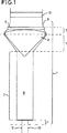
図1は、本発明による反応性流体を混合する一装置を含む触媒変換反応器の縦断面図である。
図2は、図1の反応器のエキスパンダー及びディフューザーの上流受入セクションの縦断面図である。
図3は、図1の反応器のエキスパンダー部分の縦軸に垂直な平面を取った断面図である。
図1に示す装置(1)は、入口端部(2)、混合チャンバー(4)を含むミキサー(3)、エキスパンダー(5)、インサート(6)、多孔性シールド(8)を含むディフューザー(7)及び出口端部(9)を含む。装置(1)の上流には、それぞれのガス状流体コンジット(10、11)を設ける。ガス状流体コンジットは、例えば天然ガスのような酸素含有ガスや可燃性ガスを導入する。それぞれのガス状流体の混合比は、例えばそれぞれの流体コンジットのアパーチャーを変えること又は流体自身の濃度若しくは流速を変えることのような公知の手段により制御し得る。
装置(1)の下流に示された触媒(12)は、流体フロー流内に取り付けられたモノリシック構造をなし、実質的に一様な径方向の速度プロファイルを有する拡散流体により、流体と触媒の一様な接触を起こさせる。
ガス状流体を、装置(1)に入れ、混合する。混合した流体を、エキスパンダー(5)の上流端部に入れ、軸方向に取り付けたインサート(6)の周りに等しく分割する。インサート(6)の下流セクションでは、環状の混合流体流が、インサート(6)の凸面の周囲にて径方向内向きに再入することにより合流する。ディフューザー(7)は、径方向内向きの運動量成分を混合流体流に与えてフロー分離(例えば壁から)を防止すべく、適切な形状を有する。拡散した混合流体流は、多孔性シールド(8)を通過し、触媒(12)と接触する前に原料を所望の状態にするべく十分な距離だけ進む。酸素と天然ガスを含む流体は、装置(1)に入る前に予備加熱する。触媒での原料の発火により、反応が開始し、それにより、ガス状流体が触媒に接近した際に反応温度になるようにする。従って、ミキサー(3、4)、エキスパンダー(5)、インサート(6)及びディフューザー(7)は、400℃を越える耐熱性を有する適当な材料から作り、適切には、金属合金及び類似の互換性のある材料から作る。触媒は、上述したような多孔性でモノリシックなディスク状の担体上に支持された上記のような触媒活性材料とするのが適当である。
図2は、図1のエキスパンダー(5)とインサート(6)を示し、断面A−A上に示す有効断面積(Aa)は、エキスパンダーの下流端部の内部断面積(Aid)と上流端部の内部断面積(Aiu)の差より小さい。
図3は、図2の断面A−A上の内部断面積(Ai)と有効断面積(Aa)を示し、破線は図2のAidとAiuを定める境界を示す。
次の例に関し、本発明を比制限的に説明する。
(例1) 自己発火試験
メタンと酸素を、50〜60絶対バールの範囲の圧力、300℃までの温度にて図1の装置のコンジット(10)と(11)にそれぞれ与え、完全に混合した。混合は、酸素−炭素の比が0.5とした。化合した原料は、2,000,000Nl/kg/hrのガス空間速度にて供給した。
300℃までの範囲の温度では、自己発火は起こらなかった。
(例2) 本発明による流体フロープロファイル
例1の方法を、大気中の条件にて繰り返した。結果として得られた流れを、出口端部(9)にて分析した。
フロー速度と反応器を出て行くガスの酸素濃度を、ピトー管とユニボックス(univox)により測定した。
速度プロファイルは、表面効果を無視できる20%内にて実質的に一様であった。酸素部分圧の変化は、断面に亘って1%より小さかった。
(例3) 発火の限界又は誤動作損傷
例1の方法を繰り返した。偶発的な発火が始まった。発火に続く爆発による損傷は、内部変形に限定された。方法の安全な遮断が達成された。
従って、本発明の装置は、上記のような本発明の方法において優れた様式にて使用され得ることが明らかである。The present invention relates to an apparatus for mixing and diffusing reactive fluids, a method therefor and use thereof. In particular, in the process of converting fluid substrates at high space velocities, temperatures and pressures, in particular in the partial oxidation of hydrocarbon feeds with catalysts, each fluid stream is mixed and diffused quickly and effectively. The invention relates to a device for obtaining a mixed flow with an enlarged cross-sectional area, a method therefor and a use of the device.
In a conversion method that uses a fast reaction zone, such as an oxidation or combustion zone, to convert an axially flowing gas or liquid fluid substrate, contact is made uniformly within the reaction zone at a desired residence time. This requires means for mixing the substrate in the desired ratio with the oxidizing or combustion gases. Non-uniform mixing or composition, and non-uniform rates or residence times can cause excessive or under-reactions, which generally lead to poor quality or low yield methods. For example, efficient mixing can be achieved by using a large mixing volume, a diffuser ring placed in the flow, or a small mixing volume operating at a high surface velocity. Furthermore, the mixer should not produce unacceptable differential pressure or excessively small fluid flow magnitude. This is because unacceptable changes in the critical flow impedance due to adhesion and corrosion can occur.
Additional hazards arise from the above conversion method using flammable fluids that are likely to ignite or explode upon malfunction. This hazard is due to minimizing the volume of flammable fluid in potentially dangerous zones and by operating the flammable fluid at high surface speeds to make the residence time shorter than the autoignition delay time. Can be quite low. The mixing of these fluids in high pressure conversion processes is usually the most dangerous stage of operation upstream of the reaction zone, so the volume and surface velocity of the mixed fluid upstream of the reaction zone are critical. is there.
European Patent Application 656,317 includes a description of a method for partially oxidizing a hydrocarbon feedstock with a catalyst, wherein the hydrocarbon is mixed with an oxygen-containing gas and contacted with a catalyst. The catalyst has a large twist of at least 1.1 (defined as the ratio of the path length of the gas flowing through the structure to the shortest straight path length through the structure) and at least 750 pores per square centimeter. It is held in a holding device. Preferably, the catalyst comprises a catalytically active metal supported on a support. Suitable carrier materials include refractory oxides such as silica, alumina, titania, zirconia and mixtures thereof. A catalyst comprising a zirconia refractory foam as a support is particularly mentioned as an example. Similar methods are described in European patent applications 576,096 and 629,578, and in international patent application WO 96/04200.
Catalytic partial oxidation processes that are of interest for commercial scale applications are generally at pressures as high as 10 absolute bara or more, for example about 50 absolute bar, and generally from 20,000 to 100,000,000 Nl / kg / hr. It is carried out at a high gas space velocity (standard liters of gas / kilograms / hour of catalyst) on the order of (Nl is the volume at STP (0 ° C., 1 bar absolute)). Due to the thermodynamic properties of the partial oxidation reaction, it is necessary to carry out the reaction at a high temperature in order to obtain a high yield of carbon monoxide and hydrogen at high pressure. Temperatures on the order of 800 ° C. or higher and in some cases 1000 ° C. or higher are necessary to obtain the yields required for commercial processes.
The implementation of these methods is critically important with respect to the following aspects.
(1) In order to substantially prevent the conversion to the desired product from being reduced due to insufficient or excessive oxidation, the operating conditions, uniform mixing and speed of the feed, and the catalyst and feed Need to control contact,
(2) the need to reduce the surface speed of the feedstock at the catalyst, and
(3) The need to reduce the volume and residence time of dangerous mixed feedstocks and minimize the possibility of ignition and explosion under high pressure conditions.
In such a high-pressure process in which the composition and speed are not uniform, the following means for mixing the reactive gaseous fluid are required. That is, from the viewpoint of the risk of ignition or explosion, the volume of the mixed fluid or the residence time is not increased, the surface speed is increased, an excessive differential pressure is not generated in the catalyst, and the critical flow impedance due to adhesion or corrosion is reduced. There is a need for a means of contacting the desired catalyst with the feedstock without causing unacceptable changes.
Gas and fluid mixers comprising a hollow conical chamber of increasing cross-section in the downstream direction are known, for example, in partial combustion processes for controlling the combustion of hydrocarbon gases in the presence of an oxygen-containing gas for the production of acetylene. is there. Diffusers that divert gas or fluid flow generally by increasing flow cross-section while maintaining velocity uniformity and minimizing recirculation and differential pressure (by minimizing residence time) It is known. For example, all combustion methods use fluid flow diffusers such as discs or tubular structures. The divergent extends radially perpendicular to the fluid flow path and includes an outlet aperture in the downstream disk or an extension thereof, thereby enhancing the radially outward flow of fluid by the constrained outlet aperture. . Diffusers are also known that include a hollow diffuser cone and a rotationally symmetric hollow split wing (manifold). This split wing provides a shape that helps create a truncated cone, thereby maintaining and minimizing the above characteristics.
It is clear that these known devices are not suitable for mixing and diffusing flammable fluids, for example as required by the high pressure conversion methods described above. These methods are characterized by short self-ignition delay times and high-pressure explosion hazards, which minimize ignition and explosion hazards, pressure drops, changes in critical flow impedance, and uniform From the standpoint of optimizing fluid mixing by composition and desired ratio speed to obtain a high quality, high yield conversion product, it is inconsistent with the mixer constraints described above.
Therefore, a means for mixing and diffusing flammable reactive fluids is needed to apply to the above conversion method, which impairs the yield and efficiency of the method, for example by operating under extreme conditions. It fully meets both safety and performance requirements to limit damage in the event of malfunction.
Surprisingly, it has been found that an apparatus and method for mixing and diffusing reactive fluids can be provided so that excellent mixing is obtained in the downstream direction without contradicting the above-mentioned constraints. In particular, the apparatus and method minimizes the high surface velocity fluid volume in the mixer and reduces the surface velocity at the next divergence, thereby without excessive mixer differential pressure or critical flow impedance changes. The risk of ignition and explosion is minimized, thereby minimizing operational problems and nevertheless providing a mixed fluid flow that is adapted to excellent conversion quality and yield in the next reaction zone.
Accordingly, the broadest aspect of the present invention is an apparatus for mixing ignitable or explosive reactive fluids at high temperature and pressure, which is later converted or burned by contact with a catalyst such as a (partial) oxidation catalyst. In the above apparatus having an upstream inlet end, a mixer, an expander, a diffuser, and a downstream outlet end in order, this outlet end is any of the inlet end, the mixer, and the expander. The expander has an internal cross-sectional area increased in the downstream direction so that the internal cross-sectional area of the downstream end of the expander is at least four times the internal cross-sectional area of the upstream end, The expander changes its effective cross-sectional area by providing an insert that is substantially non-porous and configured for placement within the expander. The effective cross-sectional area of the expander is smaller at any point along its length than the difference between the internal cross-sectional area at the downstream end of the expander and the internal cross-sectional area at the upstream end, and at the upstream receiving section of the diffuser. The effective cross-sectional area rapidly increases and becomes equal to the internal cross-sectional area of the diffuser, so that the internal cross-sectional area and the effective cross-sectional area in the downstream section of the diffuser are substantially constant and equal to mixing the reactive fluid It is related with the apparatus for doing.
Preferably, the effective cross-sectional area of the expander is less than 75%, more preferably less than 50%, more preferably less than 25% of the difference between the internal cross-sectional area at the downstream end of the expander and the internal cross-sectional area at the upstream end. small. The internal cross-sectional area of the downstream end of the expander is suitably at least 4 times the internal cross-sectional area of the upstream inlet end, preferably 5 to 100 times, more preferably 10 to 60 times.
The device according to the invention does not involve a significant increase in the cross-sectional area of the fluid flow (i.e. the effective cross-sectional area) in terms of maximum cross-sectional dimensions, i.e. up to 5 times, in particular up to 3 times, preferably up to 2 times. Enabling fluid mixing and diffusion by initial expansion of the fluid flow (ie by increasing the internal cross-sectional area) and then by diverging the cross-sectional area of the fluid flow to achieve the above-mentioned objectives I understand.
Here, the cross-sectional area of the flow or device is the cross-sectional area taken as a plane perpendicular to the longitudinal axis of the flow or device.
Here, the “effective” and “internal” cross-sectional areas are respectively the effective area for the fluid flow, that is, the cross-sectional area of the fluid flow, and the area defined by and surrounded by the inner wall of the apparatus, that is, (Mixed) The area surrounded by the boundary of the fluid flow. The latter may include areas that are not effective for fluid flow. The effective cross section is determined taking into account constraints on the risk of ignition or explosion and constraints on unacceptable changes in the critical flow impedance. If the internal cross-sectional area of the downstream section of the expander and the internal cross-sectional area at the upstream section of the diffuser, ie at their boundaries, change rapidly, the internal cross-section at the downstream end of the expander is the maximum internal cross-sectional area of the expander. Or set to be slightly smaller than the value corresponding to any shape of the expander or diffuser.
Here, expansion of the expander or fluid flow means a device that expands the fluid flow to provide a fluid flow front having a cross-sectional area corresponding to the effective cross-sectional area of the expander and having an increased maximum fluid flow cross-sectional dimension or A process. Preferably, such a flow front does not include any in-flow objects, partitions, etc. that support flame stabilization or ignition. Preferably, the expander includes an upstream fluid receiving end, an expansion section, and a downstream delivery end, the effective cross-sectional area is substantially as defined above, and the internal cross-sectional area is at the downstream delivery end. Is the largest.
Here, diffusion of the diffuser or fluid flow means that the fluid flow is diffused to provide a fluid flow front having an increased cross-sectional area at the downstream end of the diffuser, thereby maintaining velocity uniformity. A device or process that reduces speed. Thus, preferably, the effective cross-sectional area in the upstream receiving section of the diffuser increases rapidly and is equal to its internal cross-sectional area, so that the internal cross-sectional area and effective cross-sectional area in the downstream section of the diffuser are substantially Constant and equivalent.
Preferably, the upstream receiving section of the diffuser is shaped to direct the expanded mixed fluid flow flow in the axial direction, so that, for example, the internal cross-sectional area is slightly reduced in the downstream direction in a known manner. To substantially prevent recirculation.
Preferably, according to the present invention, any accidental flame resulting from an ignition occurring in the downstream section of the diffuser is inherent by providing a mixed flow front having an enlarged cross-sectional area as described above, Limited to the downstream section of the diffuser chamber of the apparatus of the present invention. This is because the upstream receiving section of the expander or diffuser has a uniformly high fluid flow velocity.
Here, a fluid flow is a restricted fluid duct of the desired type or form, for example consisting of continuous or polygonal boundaries such as circular, elliptical, hexagonal flows and the like. When used at high pressures and high space velocities, it is preferred to use a substantially continuously restricted fluid flow. Thus, the boundaries of the device of the present invention, such as, for example, a catalyst mounted in the reaction zone, are suitably adapted to be continuous with the downstream fluid flow boundary, thereby minimizing fluid flow deflection and thus firing. Or minimize the increased risk of explosion.
The expander includes an insert that is substantially non-porous and disposed within the expander, thereby changing its effective cross-section. Such an insert may be of any desired shape or form adapted to the above purpose. Preferably, the insert includes upstream and downstream sections, the upstream section having a cross-sectional area that increases substantially in the downstream direction, the cross-sectional area being greatest at the boundary between the upstream and downstream sections, thereby The insert is mounted axially within the expander and thereby upstream at the downstream end of the expander so as to provide a substantially annular fluid flow path within the expander having an increasing radius in the downstream direction. It has a downstream section boundary.
The outer surface of the insert and the inner surface of the upstream receiving section of the expander and diffuser may be substantially similar in shape. However, the insert can be provided with a concave upstream section to accept fluid flow in a minimal differential pressure format and similar to that in its downstream section as described above for the upstream receiving section of the diffuser. Can have a shape, thereby delivering an enlarged mixed fluid flow flow axially, thereby substantially preventing recirculation in a known manner. The insert may include a convex downstream section that projects into the diffuser section of the device.
It is convenient to define the upstream section of the expander and insert by a conical half angle, which can be in the range of 30 ° to 90 ° to the axis, preferably in the range of 30 ° to 80 °, More preferably, it exists in the range of 50 degrees-70 degrees. The cone half-angle is appropriately selected taking into account other parameters such as fluid space velocity, acceptable differential pressure, shape of the expander, insert and diffuser upstream section, and acceptable residence time within the expander, etc. The
Here, the cone half-angle refers to an angle defined by the central longitudinal axis of the cone and an arbitrary “generator”, that is, a line included in the cone surface.
Suitably, the expander and insert are defined by the ratio of the average axial length to the average diameter, which are the same or different and are in the range 1:20 to 1: 1, preferably 1:15. To 1: 1, more preferably in the range of 1: 4 to 1: 1. This relative specific dimension may depend, for example, on acceptable dwell time, acceptable differential pressure for a given operating condition, and risk of ignition or explosion.
The insert can be mounted in the expander in the desired manner. Suitably, the insert is mounted by means of a shaft or surface attachment, for example using one or more protrusions, recesses, or attachments extending or associated therewith at its upstream and / or downstream end. And / or by engaging with corresponding recesses, protrusions or fittings provided in the diffuser wall. The attachment method can be selected in a known manner taking into account the nature of the material used, its temperature and differential pressure effects, and constraints on flame stability or ignition.
Suitably, the expander and diffuser are composed of two separate parts, each including a frustoconical surface, centered about the insert as described above, eg engaging a flanged projection The surface is fixed in a known manner at truncations.
The device can be used in a desired orientation, for example, in a vertical or horizontal substrate flow. The apparatus may have any size as described above. In particular, if the residence time does not exceed the self-ignition delay time and the advantageous effects are essentially independent of size, the desired size can be achieved. In general, the device has a cross-section in its maximum size in the range of 1-50 cm, especially in the range of 5-40 cm.
The apparatus includes means for mixing the respective fluids subjected to the reaction as described above. Suitably, the apparatus comprises a mixer at its upstream end that mixes each fluid subjected to the reaction at high speed and thoroughly. Preferably, the mixer includes a respective inlet means for each fluid entering as a fluid stream at a desired space velocity. Preferably, the inlet means is provided in each conduit means for receiving the respective fluid to be mixed. Preferably, the conduit means opens in a suitable manner within the mixing chamber and may be upstream of or integral with the mixed fluid conduit means. A particular advantage of the present invention is that both unidirectional mixers and rotary mixers can be used by appropriately adapting the shape of the upstream section of the expander, insert and / or diffuser as appropriate.
The device of the present invention can be adapted to mix two or more fluids.
The apparatus of the present invention is suitable for use in high pressure conversion processes that tend to ignite or explode upon malfunction as described above. Thus, preferably, the diffuser includes a porous shield disposed at the downstream end thereof in the path of the mixed fluid flow, thereby improving the velocity profile and minimizing unintentional firing. The porous shield can include any suitable shield or fabric known in the art, and preferably includes a refractory material in the form of a fiber mesh porous monolith, such as foam. It can be seen that such a shield is suitably configured so as not to interfere with the reaction operation and is characterized by a sufficiently high mechanical integrity and thermal shock resistance to allow its use.
The components of the device may be composed of any material that meets the generally mainstream or accidental conditions used. Suitably, the diffuser, expander and insert, mixer and optional porous shield, and their respective fittings comprise a temperature stable metal alloy, preferably stainless steel or Inconel.
The porous shield may alternatively or additionally include an inorganic material such as a refractory oxide, and may include another material that provides the required mechanical strength, and more preferably, Fiber reinforcement such as a continuous inorganic fiber reinforced inorganic matrix may be included.
From the above description, it is clear that the apparatus of the present invention is brilliantly suitable for use in the process as described above to achieve the purpose of the present invention. In particular, it is clear that the device allows the implementation of such a process without its substantial interference or disruption.
Accordingly, as another aspect of the present invention, a method for mixing a reactive fluid that can ignite or explode at elevated temperatures and pressures, followed by conversion by contacting with a catalyst such as a (partial) oxidation catalyst. Or provided for conversion in the combustion zone, including providing respective fluids in the upstream stage of the method, mixing, expanding and diffusing them, and providing a mixed fluid stream in the downstream stage of the method. The downstream stage is characterized by a larger fluid flow cross-sectional area than any of the upstream, mixing, and expansion stages, and the area surrounded by the boundary of the mixed fluid flow is substantially increased in the downstream direction, The above method is provided wherein the cross-sectional area of the mixed fluid flow at any point is less than the difference between the downstream and upstream ends of the expansion stage with respect to the area surrounded by the boundary of the mixed fluid flow. Preferably, the method for mixing and diffusing the reactive fluid uses an apparatus as described above.
The method of the present invention is particularly suitable for mixing reactive fluids under conditions of risk of ignition or explosion, such as high temperatures and pressures, and more particularly, an easily combustible gas and an oxygen-containing gas. Suitable for mixing. In particular, it is determined that a particular conversion process uses a catalyst or flame reaction zone for partial or complete combustion of a gaseous fluid, and thus ignition is avoided or at least appropriately limited to the reaction zone. Important. Furthermore, the use of gaseous fluids at high temperatures and pressures significantly increases the risk of ignition. The apparatus and method of the present invention are particularly advantageous for these conversion processes.
Accordingly, another aspect of the present invention is a method of converting a fluid substrate with a catalyst comprising contacting a raw material comprising a substrate and an oxygen-containing gas with a catalyst at a high gas space velocity, high temperature and pressure, A conversion method is provided in which the fluid substrate and the oxygen-containing gas are mixed by using the method or apparatus described above prior to contacting the catalyst.
Preferably, the ratio of the cross-sectional area of the raw material introduced in the upstream stage of the process to the cross-sectional area of the mixed fluid stream discharged in the downstream stage of the process is in the range of 1: 3 to 100, more preferably in the range of 1: 5 to 50. More preferably, the raw materials are mixed so that the ratio is in the range of 1:10 to 25.
By the mixing method of the present invention, the contact performance between the catalyst and the raw material is improved due to the characteristics that have been problematic in operation using standard diffusion techniques. In particular, by utilizing features that minimize fluid flow cross-section within the constraints of surface velocity, differential pressure, and critical flow impedance corrosion and adhesion, an excellent method and apparatus for mixing is provided, which Is ideally suited for operation with any suitable mixer as described above. This sufficiently ensures the compatibility of the apparatus and method for mixing as described above when used in a catalytic fluid substrate conversion process as described above.
Excellent mixing of the fluid is obtained by appropriately performing each stage of the mixing method as described above, taking into account the operating conditions of the process used to meet the desired constraints as described above. I understood that. It can be seen that the choice of mixing, diffusion, fluid flow stabilization, etc. is determined by the nature of the conversion process and conditions, and the inherent level of ignition risk. In some conversion processes, it is essential that optimum mixing, diffusion, flow stability, etc. are required to produce substantially 100% conversion. Therefore, the risk of ignition cannot be minimized by reducing the reaction pressure or temperature, increasing the surface velocity in the reaction zone, or changing the fluid volume or residence time to reduce the flammability of the fluid. . In such a conversion process, the mixing method of the present invention allows safe operation at the maximum conversion level.
Preferably, the conversion method using a catalyst of the present invention is a method for partial oxidation of a hydrocarbon feedstock by a catalyst, and a hydrocarbon feedstock, a raw material containing an oxygen-containing gas, and a catalyst are heated at 800 to 1400 ° C. In particular a temperature in the range 950-1400 ° C., preferably 900-1300 ° C., particularly preferably 1000-1300 ° C., a pressure in the range up to 150 absolute bar, and a range in the range 20,000-100,000,000 Nl / kg / hr. Contact at a gas space velocity of A suitable process is suitably used to produce the desired ratio of carbon monoxide and hydrogen mixture from any hydrocarbon feedstock. This method is a means of obtaining a highly beneficial product known in the art as synthesis gas by a highly exothermic reaction, whereby the molar ratio of carbon monoxide to hydrogen in the product is determined by its desired molar ratio. Can be controlled by selecting the feedstock and operating conditions.
The hydrocarbon is in a gaseous phase when in contact with the catalyst. This method is particularly suitable for partial oxidation of methane, natural gas, associated gas or other sources or light hydrocarbons. In this regard, “light hydrocarbon” refers to a hydrocarbon having 1 to 5 carbon atoms. Advantageously, the method can be applied in the conversion of gas from naturally stored methane containing substantial amounts of carbon dioxide. Preferably, the feedstock comprises methane in an amount of at least 50% by volume, preferably at least 70% by volume, particularly preferably at least 80% by volume.
The hydrocarbon feedstock is contacted with the catalyst as a mixture with an oxygen-containing gas. Air is suitable for use as an oxygen-containing gas. However, it is preferred to use substantially pure oxygen as the oxygen-containing gas. In this way, the need to handle large volumes of inert gases such as nitrogen when using air as the oxygen-containing gas is avoided. The raw material may contain steam as appropriate.
Preferably, the hydrocarbon feedstock and the oxygen-containing gas are in the feedstock in an amount that provides an oxygen-carbon ratio in the range of 0.3 to 0.8, more preferably in the range of 0.45 to 0.75. Exists. Here, the oxygen-carbon ratio is the molecular state oxygen (O) relative to the carbon atoms present in the hydrocarbon feedstock. 2 ) Ratio.
Preferably the oxygen-carbon ratio is in the range of 0.45 to 0.65 and is in the range of 0.5 to 0.5 stoichiometric ratio, i.e. in the range of 0.45 to 0.55. The ratio is particularly preferred. If steam is present in the feed, the steam-carbon ratio is preferably in the range of approximately 0.0 to 3.0, particularly 0.0 to 2.0. The hydrocarbon feed, oxygen-containing gas and steam, if present, are mixed according to the present invention before contacting the catalyst.
The conversion method of the present invention can be carried out at any suitable pressure. For commercial scale applications, a high pressure, i.e. a pressure well above atmospheric pressure, is optimally applied. The process can be carried out at pressures in the range up to 150 bar absolute. Preferably, the process is carried out at a pressure in the
The method can be performed at any suitable temperature. Preferably, the feed and catalyst are contacted at elevated temperatures under suitable conditions of current high pressure in a commercial scale process. This is necessary if a high level of conversion is to be achieved at a suitable high pressure. Accordingly, the mixture of raw materials is preferably at a temperature above 800 ° C., in particular at a temperature above 950 ° C., more preferably at a temperature in the range of 800-1400 ° C., in particular at a range of 950-1400 ° C., more particularly at 1000-1300 ° C. Contact with the catalyst at a temperature in the range of Preferably, the feed mixture is preheated before contacting with the catalyst.
During the process, the feed can be provided at any suitable space velocity. It is an advantage of the method of the invention that very large gas space velocities can be achieved. Thus, the gas space velocity (expressed in standard liters of gas / kg of catalyst / hour) in the present method is in the range of 20,000 to 100,000,000 Nl / kg / hr, preferably 50,000 to 50, It is in the range of 000,000 Nl / kg / hr. Space velocities in the range of 500,000 to 30,000,000 Nl / kg / hr are particularly suitable for use in the present method.
The catalyst used in the process of the present invention comprises a catalytically active metal supported on a refractory oxide support, for example as taught in EP-A-0 656 317, the contents of which are incorporated herein. The catalytically active metal included in the catalyst is selected from group VIII of the periodic table of elements. Here, the periodic table is a CAS version as published in the 68th edition of the Chemical and Physical CRC Handbook. Suitable catalysts for use in the process of the present invention comprise a metal selected from ruthenium, rhodium, palladium, osmium, iridium and platinum. Particularly suitable are catalysts containing ruthenium, rhodium or iridium as catalytically active metals. Iridium is the most suitable catalytically active metal.
Optimal and particularly preferred catalyst supports for use in the process of the present invention are silica, alumina, titania and / or zirconia foams. Foams suitable for use in the method of the present invention are commercially available.
The raw material is preferably contacted with the catalyst under adiabatic conditions. As used herein, the term “adiabatic” refers to reaction conditions in which substantially all heat loss from the reaction zone is prevented, except for heat released to the gaseous effluent of the reactor.
The carbon monoxide and hydrogen produced by the method of the present invention can be used in any process that uses either one or both of these compounds. The mixture of carbon monoxide and hydrogen produced by this process is particularly suitable for use in the synthesis of hydrocarbons, for example by the Fischer-Tropsch process, or for the synthesis of oxygenates, for example methanol. Methods for converting carbon monoxide and hydrogen to these products are well known in the art.
Alternatively, the carbon monoxide and hydrogen product can be used for the production of hydrogen by a water gas shift reaction. Other applications of the product include hydroformylation and carbonylation processes.
The invention will now be described in a non-limiting manner with reference to FIGS.
FIG. 1 is a longitudinal sectional view of a catalytic conversion reactor including an apparatus for mixing a reactive fluid according to the present invention.
FIG. 2 is a longitudinal sectional view of the upstream receiving section of the expander and diffuser of the reactor of FIG.
3 is a cross-sectional view taken on a plane perpendicular to the longitudinal axis of the expander portion of the reactor of FIG.
The device (1) shown in FIG. 1 comprises an inlet end (2), a mixer (3) containing a mixing chamber (4), an expander (5), an insert (6), a diffuser (7) comprising a porous shield (8). ) And outlet end (9). Each gaseous fluid conduit (10, 11) is provided upstream of the device (1). The gaseous fluid conduit introduces an oxygen-containing gas such as natural gas or a combustible gas. The mixing ratio of each gaseous fluid may be controlled by known means such as changing the aperture of each fluid conduit or changing the concentration or flow rate of the fluid itself.
The catalyst (12) shown downstream of the device (1) has a monolithic structure mounted in the fluid flow stream, and the diffusion fluid having a substantially uniform radial velocity profile allows the fluid and catalyst to be Cause uniform contact.
Gaseous fluid is introduced into the device (1) and mixed. The mixed fluid is placed at the upstream end of the expander (5) and divided equally around the axially attached insert (6). In the downstream section of the insert (6), the annular mixed fluid flow merges by re-entering radially inward around the convex surface of the insert (6). The diffuser (7) has a suitable shape to impart a radially inward momentum component to the mixed fluid stream to prevent flow separation (eg from the wall). The diffused mixed fluid stream passes through the porous shield (8) and travels a sufficient distance to bring the feed to the desired state before contacting the catalyst (12). The fluid containing oxygen and natural gas is preheated before entering the device (1). The ignition of the raw material at the catalyst initiates the reaction so that the gaseous fluid reaches the reaction temperature when approaching the catalyst. Therefore, the mixer (3, 4), expander (5), insert (6) and diffuser (7) are made from a suitable material having a heat resistance of over 400 ° C, suitably a metal alloy and similar interchangeability. Made from a certain material. The catalyst is suitably a catalytically active material as described above supported on a porous, monolithic disc-shaped carrier as described above.
FIG. 2 shows the expander (5) and the insert (6) of FIG. 1, and the effective sectional area (Aa) shown on the section AA is the inner sectional area (Aid) and the upstream end of the downstream end of the expander. Is smaller than the difference in internal cross-sectional area (Aiu).
FIG. 3 shows an internal cross-sectional area (Ai) and an effective cross-sectional area (Aa) on the cross-section AA of FIG. 2, and a broken line shows a boundary defining Aid and Aiu of FIG.
The present invention will be described in a limiting manner with respect to the following examples.
(Example 1) Self-ignition test
Methane and oxygen were applied to the conduits (10) and (11), respectively, in the apparatus of FIG. 1 at pressures ranging from 50-60 absolute bar and temperatures up to 300 ° C., and mixed thoroughly. The mixing was performed with an oxygen-carbon ratio of 0.5. The combined raw materials were supplied at a gas space velocity of 2,000,000 Nl / kg / hr.
Auto-ignition did not occur at temperatures up to 300 ° C.
Example 2 Fluid flow profile according to the present invention
The method of Example 1 was repeated at atmospheric conditions. The resulting flow was analyzed at the outlet end (9).
The flow rate and the oxygen concentration of the gas exiting the reactor were measured with a Pitot tube and a univox.
The velocity profile was substantially uniform within 20% with negligible surface effects. The change in oxygen partial pressure was less than 1% across the cross section.
(Example 3) Ignition limit or malfunction damage
The method of Example 1 was repeated. Accidental fire started. Damage from the explosion following ignition was limited to internal deformation. Safe shut-off of the method was achieved.
It is therefore clear that the device of the invention can be used in an excellent manner in the method of the invention as described above.
Claims (13)
Applications Claiming Priority (3)
| Application Number | Priority Date | Filing Date | Title |
|---|---|---|---|
| EP97200033.5 | 1997-01-07 | ||
| EP97200033 | 1997-01-07 | ||
| PCT/EP1998/000141 WO1998030322A1 (en) | 1997-01-07 | 1998-01-06 | Fluid mixer and process using the same |
Publications (3)
| Publication Number | Publication Date |
|---|---|
| JP2001506183A JP2001506183A (en) | 2001-05-15 |
| JP2001506183A5 JP2001506183A5 (en) | 2005-07-14 |
| JP4156036B2 true JP4156036B2 (en) | 2008-09-24 |
Family
ID=8227915
Family Applications (1)
| Application Number | Title | Priority Date | Filing Date |
|---|---|---|---|
| JP53056498A Expired - Fee Related JP4156036B2 (en) | 1997-01-07 | 1998-01-06 | Fluid mixer and method using the same |
Country Status (12)
| Country | Link |
|---|---|
| US (1) | US6092921A (en) |
| EP (1) | EP0951345B1 (en) |
| JP (1) | JP4156036B2 (en) |
| KR (1) | KR20000069909A (en) |
| AU (1) | AU720655B2 (en) |
| CA (1) | CA2276464C (en) |
| DE (1) | DE69812585T2 (en) |
| ID (1) | ID21814A (en) |
| NO (1) | NO993339L (en) |
| NZ (1) | NZ336399A (en) |
| PL (1) | PL334445A1 (en) |
| WO (1) | WO1998030322A1 (en) |
Families Citing this family (41)
| Publication number | Priority date | Publication date | Assignee | Title |
|---|---|---|---|---|
| US6386751B1 (en) | 1997-10-24 | 2002-05-14 | Diffusion Dynamics, Inc. | Diffuser/emulsifier |
| US6702949B2 (en) | 1997-10-24 | 2004-03-09 | Microdiffusion, Inc. | Diffuser/emulsifier for aquaculture applications |
| US7654728B2 (en) | 1997-10-24 | 2010-02-02 | Revalesio Corporation | System and method for therapeutic application of dissolved oxygen |
| US7128278B2 (en) | 1997-10-24 | 2006-10-31 | Microdiffusion, Inc. | System and method for irritating with aerated water |
| EP0953842A1 (en) * | 1998-05-01 | 1999-11-03 | F. Hoffmann-La Roche Ag | Automatic analyzer with mixing chamber tapered at its lower side and socket unit sealingly connected to mixing chamber |
| EP1043271A1 (en) * | 1999-03-30 | 2000-10-11 | Shell Internationale Researchmaatschappij B.V. | Apparatus for the catalytic partial oxidation of hydrocarbons |
| ATE283450T1 (en) | 1999-09-06 | 2004-12-15 | Shell Int Research | MIXING DEVICE |
| ATE264709T1 (en) * | 2000-08-08 | 2004-05-15 | Shell Int Research | FLOW DISTRIBUTOR |
| DE10049327A1 (en) * | 2000-10-05 | 2002-04-18 | Honeywell Specialty Chemicals | Method and device for producing nickel sulfamate |
| US20070080189A1 (en) * | 2001-06-21 | 2007-04-12 | Jozef Smit Jacobus A | Catalytic reactor |
| US6514316B1 (en) | 2001-08-22 | 2003-02-04 | Mt Systems, Llc | System for improving the maximum operating temperature and lifetime of chromatographic columns |
| US7357820B2 (en) * | 2001-09-05 | 2008-04-15 | Webasto Ag | System for converting fuel and air into reformate |
| DE10219747B4 (en) * | 2002-05-02 | 2005-06-23 | Daimlerchrysler Ag | A method for preventing re-ignition in a mixture flowing to a reaction space and a reactor for carrying out the method |
| US6783749B2 (en) * | 2002-05-13 | 2004-08-31 | The Boc Group, Inc. | Gas recovery process |
| US7255848B2 (en) * | 2002-10-01 | 2007-08-14 | Regents Of The Univeristy Of Minnesota | Production of hydrogen from alcohols |
| US7262334B2 (en) * | 2002-11-13 | 2007-08-28 | Regents Of The University Of Minnesota | Catalytic partial oxidation of hydrocarbons |
| US20040133057A1 (en) * | 2003-01-02 | 2004-07-08 | Conocophillips Company | Gaseous hydrocarbon-oxygen bubble tank mixer |
| US7108838B2 (en) | 2003-10-30 | 2006-09-19 | Conocophillips Company | Feed mixer for a partial oxidation reactor |
| WO2005116168A1 (en) | 2004-05-25 | 2005-12-08 | Regents Of The University Of Minnesota | Production of olefins having a functional group |
| US7416571B2 (en) | 2005-03-09 | 2008-08-26 | Conocophillips Company | Compact mixer for the mixing of gaseous hydrocarbon and gaseous oxidants |
| US20100008180A1 (en) * | 2006-07-03 | 2010-01-14 | Soren Friis Krogh | Apparatus for dissolving solid particles and liquid substances in a liquid |
| AU2007349224B2 (en) | 2006-10-25 | 2014-04-03 | Revalesio Corporation | Methods of wound care and treatment |
| US8784897B2 (en) | 2006-10-25 | 2014-07-22 | Revalesio Corporation | Methods of therapeutic treatment of eyes |
| US8445546B2 (en) | 2006-10-25 | 2013-05-21 | Revalesio Corporation | Electrokinetically-altered fluids comprising charge-stabilized gas-containing nanostructures |
| AU2007308838B2 (en) | 2006-10-25 | 2014-03-13 | Revalesio Corporation | Mixing device and output fluids of same |
| AU2007308840C1 (en) | 2006-10-25 | 2014-09-25 | Revalesio Corporation | Methods of therapeutic treatment of eyes and other human tissues using an oxygen-enriched solution |
| US8784898B2 (en) | 2006-10-25 | 2014-07-22 | Revalesio Corporation | Methods of wound care and treatment |
| US8609148B2 (en) | 2006-10-25 | 2013-12-17 | Revalesio Corporation | Methods of therapeutic treatment of eyes |
| WO2008052361A1 (en) * | 2006-11-03 | 2008-05-08 | Nxtgen Emission Controls Inc. | Fuel processor |
| DE602007009175D1 (en) | 2006-12-09 | 2010-10-28 | Haldor Topsoe As | Method and apparatus for mixing two or more fluid streams |
| US9523090B2 (en) | 2007-10-25 | 2016-12-20 | Revalesio Corporation | Compositions and methods for treating inflammation |
| US10125359B2 (en) | 2007-10-25 | 2018-11-13 | Revalesio Corporation | Compositions and methods for treating inflammation |
| US9745567B2 (en) | 2008-04-28 | 2017-08-29 | Revalesio Corporation | Compositions and methods for treating multiple sclerosis |
| MX2010011856A (en) | 2008-05-01 | 2011-02-15 | Revalesio Corp | Compositions and methods for treating digestive disorders. |
| US8815292B2 (en) | 2009-04-27 | 2014-08-26 | Revalesio Corporation | Compositions and methods for treating insulin resistance and diabetes mellitus |
| KR20130114581A (en) | 2010-05-07 | 2013-10-18 | 레발레시오 코퍼레이션 | Compositions and methods for enhancing physiological performance and recovery time |
| JP2013533320A (en) | 2010-08-12 | 2013-08-22 | レバレジオ コーポレイション | Compositions and methods for treating tauopathy |
| FR3008626B1 (en) * | 2013-07-19 | 2015-08-07 | Arkema France | REACTOR FOR PREPARING HYDROGEN CYANIDE BY THE ANDRUSSOW PROCESS, EQUIPMENT COMPRISING SAID REACTOR AND METHOD USING SUCH EQUIPMENT |
| JP6291903B2 (en) * | 2014-02-26 | 2018-03-14 | 株式会社ジェイテクト | Kneading equipment |
| CA2935564A1 (en) * | 2016-07-07 | 2018-01-07 | Nova Chemicals Corporation | Inherently safe oxygen/hydrocarbon gas mixer |
| CN111964052B (en) * | 2019-05-19 | 2021-11-26 | 宁波方太厨具有限公司 | Injection pipe for gas stove |
Family Cites Families (11)
| Publication number | Priority date | Publication date | Assignee | Title |
|---|---|---|---|---|
| US2021092A (en) * | 1931-02-09 | 1935-11-12 | Teliet Jean Antoine Marcel | Improved method and means for incorporating a fluid to a stream of a fluid or of a pulverulent solid |
| US3020234A (en) * | 1959-10-06 | 1962-02-06 | Union Carbide Corp | Method and apparatus for producing a homogeneous thermal insulation mixture |
| DE1258835B (en) * | 1964-08-28 | 1968-01-18 | James R Lage Dr | Mixing device |
| GB1262436A (en) * | 1970-04-03 | 1972-02-02 | Shell Int Research | Apparatus for mixing two gas streams |
| US3702619A (en) * | 1971-01-28 | 1972-11-14 | Shell Oil Co | In-line mixing apparatus for gases |
| US4008580A (en) * | 1974-12-04 | 1977-02-22 | Frigoscandia Contracting, Inc. | Initial quick freeze pan for direct refrigerant contact cooler |
| US4299655A (en) * | 1978-03-13 | 1981-11-10 | Beloit Corporation | Foam generator for papermaking machine |
| JPS60137425A (en) * | 1983-12-26 | 1985-07-22 | Hitachi Ltd | Fluid mixing device |
| ES2019383B3 (en) * | 1986-05-27 | 1991-06-16 | Ici Plc | METHOD TO INITIATE A PROCESS FOR THE PRODUCTION OF A GASEOUS CURRENT CONTAINING HYDROGEN AND CARBON OXIDES. |
| US5112527A (en) * | 1991-04-02 | 1992-05-12 | Amoco Corporation | Process for converting natural gas to synthesis gas |
| NZ264970A (en) * | 1993-11-29 | 1997-02-24 | Shell Int Research | Hydrocarbon oxidation; catalytic partial oxidation of hydrocarbon feedstock, preparation of carbon monoxide/hydrogen mixture, details regarding catalyst arrangement |
-
1998
- 1998-01-06 CA CA002276464A patent/CA2276464C/en not_active Expired - Fee Related
- 1998-01-06 KR KR1019997006121A patent/KR20000069909A/en not_active Application Discontinuation
- 1998-01-06 EP EP98905287A patent/EP0951345B1/en not_active Expired - Lifetime
- 1998-01-06 DE DE69812585T patent/DE69812585T2/en not_active Expired - Fee Related
- 1998-01-06 AU AU60935/98A patent/AU720655B2/en not_active Ceased
- 1998-01-06 ID IDW990651A patent/ID21814A/en unknown
- 1998-01-06 NZ NZ336399A patent/NZ336399A/en unknown
- 1998-01-06 JP JP53056498A patent/JP4156036B2/en not_active Expired - Fee Related
- 1998-01-06 WO PCT/EP1998/000141 patent/WO1998030322A1/en active IP Right Grant
- 1998-01-06 PL PL98334445A patent/PL334445A1/en unknown
- 1998-01-07 US US09/004,072 patent/US6092921A/en not_active Expired - Fee Related
-
1999
- 1999-07-06 NO NO993339A patent/NO993339L/en not_active Application Discontinuation
Also Published As
| Publication number | Publication date |
|---|---|
| EP0951345A1 (en) | 1999-10-27 |
| NO993339D0 (en) | 1999-07-06 |
| DE69812585D1 (en) | 2003-04-30 |
| AU6093598A (en) | 1998-08-03 |
| JP2001506183A (en) | 2001-05-15 |
| NO993339L (en) | 1999-09-02 |
| US6092921A (en) | 2000-07-25 |
| EP0951345B1 (en) | 2003-03-26 |
| CA2276464A1 (en) | 1998-07-16 |
| NZ336399A (en) | 2000-03-27 |
| WO1998030322A1 (en) | 1998-07-16 |
| PL334445A1 (en) | 2000-02-28 |
| DE69812585T2 (en) | 2004-01-08 |
| ID21814A (en) | 1999-07-29 |
| AU720655B2 (en) | 2000-06-08 |
| CA2276464C (en) | 2007-05-08 |
| KR20000069909A (en) | 2000-11-25 |
Similar Documents
| Publication | Publication Date | Title |
|---|---|---|
| JP4156036B2 (en) | Fluid mixer and method using the same | |
| CA2383833C (en) | Mixing device | |
| CN101304804B (en) | Fluid mixing device inserted in or combined with a reactor | |
| KR100437559B1 (en) | Hot gas reactor and a chemical vapor reaction process using same | |
| JPH01145301A (en) | Preparation of synthetic gas from hydrocarbon material | |
| US20080031800A1 (en) | Process and apparatus for generating hydrogen | |
| JP2002508733A (en) | Multiple injector autothermal reforming method and apparatus for producing syngas | |
| JPH01159037A (en) | Gas mixing and distribution apparatus | |
| MXPA99008136A (en) | Hot gas reactor and process to use the mi | |
| JPH046841B2 (en) | ||
| JP2008214165A (en) | Combustible gas mixing method and mixer | |
| EP1307281B1 (en) | Flow distributor | |
| MXPA99006216A (en) | Fluid mixer and process using the same | |
| KR20020003187A (en) | Catalytic reactor | |
| CZ241199A3 (en) | Liquid agitator and way of use thereof | |
| EP1043271A1 (en) | Apparatus for the catalytic partial oxidation of hydrocarbons | |
| WO2020092595A1 (en) | Burners for use in producing synthesis gas | |
| JPH0524844B2 (en) |
Legal Events
| Date | Code | Title | Description |
|---|---|---|---|
| A521 | Written amendment |
Free format text: JAPANESE INTERMEDIATE CODE: A523 Effective date: 20041122 |
|
| A621 | Written request for application examination |
Free format text: JAPANESE INTERMEDIATE CODE: A621 Effective date: 20041122 |
|
| A131 | Notification of reasons for refusal |
Free format text: JAPANESE INTERMEDIATE CODE: A131 Effective date: 20070807 |
|
| A977 | Report on retrieval |
Free format text: JAPANESE INTERMEDIATE CODE: A971007 Effective date: 20070726 |
|
| A521 | Written amendment |
Free format text: JAPANESE INTERMEDIATE CODE: A523 Effective date: 20071106 |
|
| TRDD | Decision of grant or rejection written | ||
| A01 | Written decision to grant a patent or to grant a registration (utility model) |
Free format text: JAPANESE INTERMEDIATE CODE: A01 Effective date: 20080701 |
|
| A01 | Written decision to grant a patent or to grant a registration (utility model) |
Free format text: JAPANESE INTERMEDIATE CODE: A01 |
|
| A61 | First payment of annual fees (during grant procedure) |
Free format text: JAPANESE INTERMEDIATE CODE: A61 Effective date: 20080709 |
|
| FPAY | Renewal fee payment (event date is renewal date of database) |
Free format text: PAYMENT UNTIL: 20110718 Year of fee payment: 3 |
|
| R150 | Certificate of patent or registration of utility model |
Free format text: JAPANESE INTERMEDIATE CODE: R150 |
|
| LAPS | Cancellation because of no payment of annual fees |