JP4154388B2 - Detection device for detecting the state of electromagnetic waves transmitted through an object - Google Patents
Detection device for detecting the state of electromagnetic waves transmitted through an object Download PDFInfo
- Publication number
- JP4154388B2 JP4154388B2 JP2004376370A JP2004376370A JP4154388B2 JP 4154388 B2 JP4154388 B2 JP 4154388B2 JP 2004376370 A JP2004376370 A JP 2004376370A JP 2004376370 A JP2004376370 A JP 2004376370A JP 4154388 B2 JP4154388 B2 JP 4154388B2
- Authority
- JP
- Japan
- Prior art keywords
- terahertz wave
- waveguide
- substance
- gap
- parallel plate
- Prior art date
- Legal status (The legal status is an assumption and is not a legal conclusion. Google has not performed a legal analysis and makes no representation as to the accuracy of the status listed.)
- Expired - Fee Related
Links
- 238000001514 detection method Methods 0.000 title claims description 7
- 230000005540 biological transmission Effects 0.000 claims description 30
- 229910052751 metal Inorganic materials 0.000 claims description 20
- 239000002184 metal Substances 0.000 claims description 20
- 230000000644 propagated effect Effects 0.000 claims description 3
- 239000000126 substance Substances 0.000 description 35
- 238000000034 method Methods 0.000 description 25
- 239000012530 fluid Substances 0.000 description 19
- 239000013078 crystal Substances 0.000 description 14
- 238000001228 spectrum Methods 0.000 description 13
- 230000003287 optical effect Effects 0.000 description 9
- 238000005259 measurement Methods 0.000 description 8
- 238000000862 absorption spectrum Methods 0.000 description 7
- 239000002245 particle Substances 0.000 description 7
- 239000004793 Polystyrene Substances 0.000 description 6
- 230000001678 irradiating effect Effects 0.000 description 6
- 229920002223 polystyrene Polymers 0.000 description 6
- XLYOFNOQVPJJNP-UHFFFAOYSA-N water Substances O XLYOFNOQVPJJNP-UHFFFAOYSA-N 0.000 description 6
- 238000004458 analytical method Methods 0.000 description 5
- 238000005516 engineering process Methods 0.000 description 5
- 239000006185 dispersion Substances 0.000 description 4
- 239000000463 material Substances 0.000 description 4
- 108090000623 proteins and genes Proteins 0.000 description 4
- 102000004169 proteins and genes Human genes 0.000 description 4
- 239000000243 solution Substances 0.000 description 4
- 229910001218 Gallium arsenide Inorganic materials 0.000 description 3
- 238000010521 absorption reaction Methods 0.000 description 3
- 239000008280 blood Substances 0.000 description 3
- 210000004369 blood Anatomy 0.000 description 3
- 238000002347 injection Methods 0.000 description 3
- 239000007924 injection Substances 0.000 description 3
- 239000007788 liquid Substances 0.000 description 3
- 230000001902 propagating effect Effects 0.000 description 3
- 239000004065 semiconductor Substances 0.000 description 3
- 230000035945 sensitivity Effects 0.000 description 3
- YBJHBAHKTGYVGT-ZKWXMUAHSA-N (+)-Biotin Chemical compound N1C(=O)N[C@@H]2[C@H](CCCCC(=O)O)SC[C@@H]21 YBJHBAHKTGYVGT-ZKWXMUAHSA-N 0.000 description 2
- JBRZTFJDHDCESZ-UHFFFAOYSA-N AsGa Chemical compound [As]#[Ga] JBRZTFJDHDCESZ-UHFFFAOYSA-N 0.000 description 2
- 229910007709 ZnTe Inorganic materials 0.000 description 2
- 239000007864 aqueous solution Substances 0.000 description 2
- 210000001124 body fluid Anatomy 0.000 description 2
- 239000010839 body fluid Substances 0.000 description 2
- 239000003989 dielectric material Substances 0.000 description 2
- CSJLBAMHHLJAAS-UHFFFAOYSA-N diethylaminosulfur trifluoride Substances CCN(CC)S(F)(F)F CSJLBAMHHLJAAS-UHFFFAOYSA-N 0.000 description 2
- 230000000694 effects Effects 0.000 description 2
- 230000009969 flowable effect Effects 0.000 description 2
- 230000010354 integration Effects 0.000 description 2
- 239000012528 membrane Substances 0.000 description 2
- 239000012466 permeate Substances 0.000 description 2
- 230000010287 polarization Effects 0.000 description 2
- 239000000843 powder Substances 0.000 description 2
- 238000005070 sampling Methods 0.000 description 2
- 239000000758 substrate Substances 0.000 description 2
- 239000013076 target substance Substances 0.000 description 2
- 238000000411 transmission spectrum Methods 0.000 description 2
- 108090001008 Avidin Proteins 0.000 description 1
- 229960002685 biotin Drugs 0.000 description 1
- 235000020958 biotin Nutrition 0.000 description 1
- 239000011616 biotin Substances 0.000 description 1
- 238000000701 chemical imaging Methods 0.000 description 1
- 238000010586 diagram Methods 0.000 description 1
- 230000005684 electric field Effects 0.000 description 1
- 238000003384 imaging method Methods 0.000 description 1
- 238000007689 inspection Methods 0.000 description 1
- 238000009434 installation Methods 0.000 description 1
- 230000010355 oscillation Effects 0.000 description 1
- 230000000704 physical effect Effects 0.000 description 1
- 239000011347 resin Substances 0.000 description 1
- 229920005989 resin Polymers 0.000 description 1
- 239000007787 solid Substances 0.000 description 1
- 238000004611 spectroscopical analysis Methods 0.000 description 1
- 238000010183 spectrum analysis Methods 0.000 description 1
- 230000001131 transforming effect Effects 0.000 description 1
- 238000002235 transmission spectroscopy Methods 0.000 description 1
Images


Classifications
-
- G—PHYSICS
- G01—MEASURING; TESTING
- G01N—INVESTIGATING OR ANALYSING MATERIALS BY DETERMINING THEIR CHEMICAL OR PHYSICAL PROPERTIES
- G01N21/00—Investigating or analysing materials by the use of optical means, i.e. using sub-millimetre waves, infrared, visible or ultraviolet light
- G01N21/17—Systems in which incident light is modified in accordance with the properties of the material investigated
- G01N21/25—Colour; Spectral properties, i.e. comparison of effect of material on the light at two or more different wavelengths or wavelength bands
- G01N21/31—Investigating relative effect of material at wavelengths characteristic of specific elements or molecules, e.g. atomic absorption spectrometry
- G01N21/35—Investigating relative effect of material at wavelengths characteristic of specific elements or molecules, e.g. atomic absorption spectrometry using infrared light
- G01N21/3581—Investigating relative effect of material at wavelengths characteristic of specific elements or molecules, e.g. atomic absorption spectrometry using infrared light using far infrared light; using Terahertz radiation
-
- G—PHYSICS
- G01—MEASURING; TESTING
- G01N—INVESTIGATING OR ANALYSING MATERIALS BY DETERMINING THEIR CHEMICAL OR PHYSICAL PROPERTIES
- G01N21/00—Investigating or analysing materials by the use of optical means, i.e. using sub-millimetre waves, infrared, visible or ultraviolet light
- G01N21/17—Systems in which incident light is modified in accordance with the properties of the material investigated
- G01N21/25—Colour; Spectral properties, i.e. comparison of effect of material on the light at two or more different wavelengths or wavelength bands
- G01N21/31—Investigating relative effect of material at wavelengths characteristic of specific elements or molecules, e.g. atomic absorption spectrometry
- G01N21/35—Investigating relative effect of material at wavelengths characteristic of specific elements or molecules, e.g. atomic absorption spectrometry using infrared light
- G01N21/3577—Investigating relative effect of material at wavelengths characteristic of specific elements or molecules, e.g. atomic absorption spectrometry using infrared light for analysing liquids, e.g. polluted water
Description
伝搬する電磁波の伝搬状態の変化を検出する技術に関し、検出した情報を用いて物質の計測・感知・分析を行う。 With regard to technology for detecting changes in the propagation state of propagating electromagnetic waves, measurement, sensing, and analysis of substances are performed using the detected information.
近年、いわゆるテラヘルツ波を応用した技術が注目されている。テラヘルツ波を利用した分光分析やイメージングなどが、産業応用として期待されている。 In recent years, a technique applying so-called terahertz waves has attracted attention. Spectral analysis and imaging using terahertz waves are expected as industrial applications.
例えば、テラヘルツ波の応用分野として、X線に代わる安全な透視検査装置としてイメージングを行なう技術、物質内部の吸収スペクトルや複素誘電率を求めて結合状態を調べる分光技術、生体分子の解析技術、キャリア濃度や移動度を評価する技術などが開発されている。 For example, as a field of application of terahertz waves, imaging technology as a safe fluoroscopic inspection device that replaces X-rays, spectroscopic technology that examines the binding state by obtaining the absorption spectrum and complex dielectric constant inside the substance, biomolecule analysis technology, carrier Technologies for evaluating concentration and mobility have been developed.
中でもテラヘルツ波を用いて分光学的手法により物質を分析する方法として、テラヘルツ波を分析対象物質に照射し、透過あるいは反射したテラヘルツ波のスペクトルを得る方法が公知技術として知られている。 In particular, as a method for analyzing a substance by a spectroscopic method using a terahertz wave, a method for obtaining a spectrum of a transmitted or reflected terahertz wave by irradiating the target substance with the terahertz wave is known as a known technique.
ところで、水は30GHz〜30THzの周波数領域に非常に強い吸収スペクトルを多数持っている。このため、例えば液体の水が入った厚さ1ミリの容器は、テラヘルツ波をほとんど完全に遮断してしまう。ゆえに、透過したテラヘルツ波から物質の情報を得るいわゆる透過分光が出来ない。 By the way, water has many very strong absorption spectra in the frequency range of 30 GHz to 30 THz. For this reason, for example, a 1 mm-thick container containing liquid water almost completely blocks terahertz waves. Therefore, so-called transmission spectroscopy that obtains material information from the transmitted terahertz wave cannot be performed.
そこで水など非常に強い吸収スペクトル帯をテラヘルツ領域にもつ物質およびその中に含まれる分子などの吸収スペクトルや複素誘電率を求める方法として、非特許文献1に開示されているようなプリズムでの全反射時に発生するテラヘルツ波のエバネッセント波を用いる方法が知られている。これは、テラヘルツ波発生源から発せられたテラヘルツ波をプリズムの第一の面に入射させ、第二の面で全反射し、第三の面から出射したテラヘルツ波を検出器で検出し、第二の面でテラヘルツ波が全反射するに伴い発生するテラヘルツ波のエバネッセント波と相互作用するように第二の面上に試料を設置することで、試料を分光学的に分析する方法である。この方法では、固体・粉末・液体などの形態の試料を分析することができる。
非特許文献1の方法では空間光学系を用いているため、システムの小型化が困難であり、また光学調整が困難である。そこで、本発明はシステムの小型化や光学調整の容易な検出装置を提供するものである。
In the method of Non-Patent
そこで、本発明は、
被対象物を透過した電磁波の状態を検出するための検出装置であって、
電磁波を発生するための発生手段と、
前記電磁波を伝送するための伝送路と、
前記電磁波を検出するための検出手段とを備え、
前記伝送路中で前記電磁波が分布する領域の一部に通路を有し、
前記発生手段により発生した電磁波が、前記通路中の被測定対象物を透過し、前記検出手段により前記電磁波の状態を検出する検出装置を提供するものである。
Therefore, the present invention provides
A detection device for detecting the state of an electromagnetic wave transmitted through an object,
Generating means for generating electromagnetic waves;
A transmission path for transmitting the electromagnetic wave;
Detecting means for detecting the electromagnetic wave,
Having a passage in a part of a region where the electromagnetic wave is distributed in the transmission path;
An electromagnetic wave generated by the generating means is transmitted through the object to be measured in the passage, and a detection device for detecting the state of the electromagnetic wave by the detecting means is provided.
ここで、前記発生手段や前記検知手段は、1つでもいいが、複数設ければ測定精度が上がるのでより好ましい。 Here, although the number of the generating means and the detecting means may be one, it is more preferable if a plurality of the generating means and the detecting means are provided because measurement accuracy is improved.
本発明により、微装置自体の小型化、光学調整の軽減が図れる。 According to the present invention, the miniaturization apparatus itself can be reduced in size and optical adjustment can be reduced.
以下に具体的に説明する。テラヘルツ波を導波する伝送路の内部(例えば導波路のコア、金属導波管(金属平行平板導波路を含む)の内部、伝送線路の接地線と信号線に挟まれた誘電体部分など)に、液体や紛体など流動性を持つ物質を導入できる流路を持つことが好ましいが、被対象物質を伝送路中に配置できる通路であればなんでもよい。前記流路は電磁波の伝搬方向と平行ではなく、また伝送路中における電磁が強く分布している領域を通るよう設置されていることが好ましい。前記伝送路を導波するテラヘルツ波と前記流路中にある流動性を持つ物質が相互作用し、前記流動性を持つ物質を透過したテラヘルツ波の伝搬状態・スペクトルが変化することを利用し、前記流動性物質を前記流路に導入する前後のテラヘルツ波の伝搬状態・スペクトルを比較することで、前記流動性物質の物性を調べたり、物質の同定を行ったりするものである。 This will be specifically described below. The inside of a transmission line that guides terahertz waves (for example, the core of a waveguide, the inside of a metal waveguide (including a metal parallel plate waveguide), a dielectric part sandwiched between the ground line and the signal line of the transmission line, etc.) In addition, it is preferable to have a flow path capable of introducing a fluid material such as a liquid or powder, but any path can be used as long as the target substance can be disposed in the transmission path. It is preferable that the flow path is not parallel to the propagation direction of the electromagnetic wave and passes through a region where electromagnetic waves are strongly distributed in the transmission path. Utilizing the fact that the terahertz wave guided through the transmission line interacts with a fluid substance in the flow path, and the propagation state / spectrum of the terahertz wave transmitted through the fluid substance changes, By comparing the propagation state / spectrum of the terahertz wave before and after introducing the fluid substance into the flow path, the physical properties of the fluid substance are examined or the substance is identified.
前記流路のテラヘルツ波伝搬方向に対する厚さを十分薄くすることで、水など非常に強い吸収を持つ物質に対しても前記テラヘルツ波は前記試料を透過できるようにする。 By sufficiently reducing the thickness of the flow path in the terahertz wave propagation direction, the terahertz wave can pass through the sample even for a substance having very strong absorption such as water.
前記伝送路として導波路を用いる場合は、導波路を構成するクラッドおよびコアの一部に空隙を設けることで流路としても良い。また前記伝送路として金属導波管を用いる場合は、金属導波管を構成する導波管内部の空洞内部に誘電体でできたパイプ状の中空部材を設けることで流路としても良いし、あるいは導波管内部が誘電体で満たされている場合は、前記誘電体の一部に空隙を設けることで流路としても良い。また前記伝送路として伝送線路を用いる場合は、伝送線路を構成する設置線と信号線の間の誘電体部分の一部に空隙を設けることで、流路としても良い。 When a waveguide is used as the transmission path, a flow path may be formed by providing a gap in a part of the clad and core constituting the waveguide. Further, when a metal waveguide is used as the transmission path, a pipe-shaped hollow member made of a dielectric material may be provided inside the cavity inside the waveguide that constitutes the metal waveguide. Alternatively, when the inside of the waveguide is filled with a dielectric, a flow path may be formed by providing a gap in a part of the dielectric. When a transmission line is used as the transmission line, a flow path may be formed by providing a gap in a part of the dielectric portion between the installation line and the signal line constituting the transmission line.
前記伝送線路として金属導波管を用いる場合で、かつ金属導波管内部が空洞である場合は、空洞内部に誘電体でできたパイプ状の中空部材を設けることで流路とすることができる。この場合流路を構成するパイプ状の中空部材は低損失・低分散・低屈折率な誘電体であることが望ましい。また金属導波管内部を誘電体で満たし、前記誘電体の一部に空隙を設けることで流路とする場合は、前記誘電体は低損失・低分散・低屈折率であることが望ましい。この流路を設けることにより、微量の資料しか得られない場合でも測定可能になる。さらに、流路を外気から遮蔽した状態で設けることにより、外気に対し敏感に影響される物質のセンシングが可能になる。 When a metal waveguide is used as the transmission line and the inside of the metal waveguide is a cavity, a flow path can be obtained by providing a pipe-shaped hollow member made of a dielectric inside the cavity. . In this case, it is desirable that the pipe-shaped hollow member constituting the flow path is a dielectric material having low loss, low dispersion, and low refractive index. In addition, when the metal waveguide is filled with a dielectric and a flow path is formed by providing a gap in a part of the dielectric, the dielectric preferably has low loss, low dispersion, and a low refractive index. By providing this flow path, measurement can be performed even when only a very small amount of data can be obtained. Furthermore, by providing the flow path in a state shielded from the outside air, it is possible to sense a substance sensitive to the outside air.
テラヘルツ波は、外部から伝送路に結合させてもよいが、テラヘルツ波発生源を伝送路の一部に集積化させても良い。例えば導波路や導波管を用いる場合は、導波路や導波管の端面にテラヘルツ波発生源を集積化させても良いし、伝送線路を用いる場合は、伝送線路上にテラヘルツ波発生源を集積化させても良い。また同様に、伝送路を伝搬したテラヘルツ波を外部に放射させテラヘルツ波検出器でテラヘルツ波を検出しても良いが、テラヘルツ波検出器を伝送路の一部に集積化しても良い。この場合テラヘルツ波が空気中の水分の影響を受けないことや、光学調整が不要になることや、小型化が図れるといった利点がある。 The terahertz wave may be coupled to the transmission path from the outside, but the terahertz wave generation source may be integrated in a part of the transmission path. For example, when a waveguide or a waveguide is used, a terahertz wave generation source may be integrated on the end face of the waveguide or the waveguide. When a transmission line is used, a terahertz wave generation source is provided on the transmission line. It may be integrated. Similarly, the terahertz wave propagated through the transmission line may be emitted to the outside and the terahertz wave detector may detect the terahertz wave. However, the terahertz wave detector may be integrated in a part of the transmission line. In this case, there are advantages that the terahertz wave is not affected by moisture in the air, optical adjustment is unnecessary, and miniaturization can be achieved.
テラヘルツ波発生源および発生方法として、低温成長ヒ化ガリウム上に形成された光伝導アンテナに電圧をかけフェムト秒レーザを照射する方法が一例として挙げられる。テラヘルツ波発生源の集積化の一例として、前記光伝導アンテナを例えば導波管の一端面に設置しても良い。またテラヘルツ検出器として、光伝導アンテナに電圧をかけずにフェムト秒レーザを照射し、電流を測定する方法が挙げられる。テラヘルツ波検出器の集積化の一例として、前記光伝導アンテナを導波管の単面のうちテラヘルツ波が透過して来る方の端面に設置しても良い。これにより、テラヘルツ波が空気中の水分の影響を受けることなく、センシングが可能になる。 An example of a terahertz wave generation source and generation method is a method of applying a voltage to a photoconductive antenna formed on low-temperature grown gallium arsenide and irradiating a femtosecond laser. As an example of integration of a terahertz wave generation source, the photoconductive antenna may be installed on one end face of a waveguide, for example. Further, as a terahertz detector, there is a method of measuring a current by irradiating a photoconductive antenna with a femtosecond laser without applying a voltage. As an example of integration of the terahertz wave detector, the photoconductive antenna may be installed on the end surface of the single surface of the waveguide through which the terahertz wave is transmitted. As a result, sensing is possible without the terahertz wave being affected by moisture in the air.
またテラヘルツ波が透過して来る方の端面に電気光学効果をもつEO結晶(例えばZnTe)を設置し、EO結晶の結晶方位・テラヘルツ波の偏光方向を適切に選ぶことで、EO結晶の反射率や屈折率が偏光依存性を持って変化する現象を利用した公知の方法を用いても良い。 In addition, an EO crystal (for example, ZnTe) having an electro-optic effect is installed on the end face through which the terahertz wave is transmitted, and the reflectance of the EO crystal is selected by appropriately selecting the crystal orientation of the EO crystal and the polarization direction of the terahertz wave. Alternatively, a known method using a phenomenon in which the refractive index changes with polarization dependency may be used.
またテラヘルツ波発生源を集積化する方法の別の例として、非線形性を持った物質(たとえばDAST結晶)を導波管や導波路の内部や端面に設置しても良い。 As another example of a method for integrating terahertz wave generation sources, a non-linear material (for example, a DAST crystal) may be installed inside or on the end face of a waveguide or waveguide.
また例えば血液のように別の場所から試料を採取する必要があるとき、被測定対象物を取得するための手段として採取器具(例えば注射針)と得られた被測定対象物を通路に接続するための接続手段として前記流路を別の流路(例えばチューブ)で接続することで、試料の採取と同時に試料を所定の位置に設置できる。また、流路中の試料は外気と接触する面積が小さいため、外気に影響されやすい試料を測定する上で有利である。 In addition, when it is necessary to collect a sample from another place such as blood, a sampling instrument (for example, an injection needle) and the measured object to be measured are connected to a passage as means for acquiring the object to be measured. By connecting the flow path with another flow path (for example, a tube) as connection means for the purpose, the sample can be placed at a predetermined position simultaneously with the collection of the sample. Further, since the sample in the channel has a small area in contact with the outside air, it is advantageous in measuring a sample that is easily affected by the outside air.
流動性試料に含まれる特定(一種類または複数種類)の粒子または分子をセンシングする場合、流路の一端から流動性試料を導入し、別の一端に特定の粒子または分子を透過せずその他の流動性物質(例えば水)を透過するフィルタ(例えば半透膜)を設けることで、センシング部における特定の粒子または分子の濃度を高めつつセンシングを行なうことができる。この方法では、試料の濃縮とセンシングを続けてまたは同時に行なうことができ、作業効率上有利である。 When sensing specific (single or multiple) particles or molecules contained in a flowable sample, the flowable sample is introduced from one end of the flow path, and the other end does not permeate specific particles or molecules. By providing a filter (for example, a semipermeable membrane) that transmits a fluid substance (for example, water), sensing can be performed while increasing the concentration of specific particles or molecules in the sensing unit. In this method, sample concentration and sensing can be performed continuously or simultaneously, which is advantageous in terms of work efficiency.
また、流路の壁面に特定(一種類または複数種類)の粒子または分子を吸着あるいは結合する物質を設置し、流動性物質に含まれる特定の粒子または分子を流路壁面に捉え、前記粒子または分子を吸着または結合したことによって前記流路壁面に設置された物質の複素誘電率や吸収スペクトルの変化から、流動性試料およびその中に含まれる粒子または分子のセンシングができる。 In addition, a substance that adsorbs or binds specific (one or more types) particles or molecules to the wall surface of the flow path is installed, and the specific particles or molecules contained in the fluid substance are captured on the flow path wall surface, and the particles or From the change of the complex dielectric constant and absorption spectrum of the substance placed on the channel wall surface by adsorbing or binding the molecules, the fluid sample and the particles or molecules contained therein can be sensed.
以下に、本発明による光学素子の実施形態について、図面を参照して説明する。 Embodiments of an optical element according to the present invention will be described below with reference to the drawings.
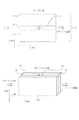
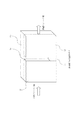
本発明による第一の実施例は、図1のような導波路および図2のような測定・感知・分析装置を提供するものである。以下詳細を図1および図2に示しながら説明する。平行平板導波路10は、金属板11aおよび11bが、ポリスチレン板12を挟む構造となっている。前記ポリスチレン板12には、空隙13が設けられている。金属板11aと11bの向かい合う面の間隔は約100μmである。また金属板11aと11bの典型的な大きさは、x方向、z方向ともに10mmから20mm程度である。空隙13はx方向に約50μmである。空隙13には、流体など流動性を持った試料を導入することができる。この例では、金属板11a、11bの間隔を100μmとしたが、これに限るものではない。また金属板11aおよび11bに挟まれた部材としてポリスチレンを挙げたが、これに限るものではない。金属板11aおよび11bに挟まれた部材としては、テラヘルツ波に対し吸収(損失)・分散が十分小さいものであれば、他の誘電体(樹脂や半導体)でも良い。また屈折率が1に近い方が望ましい。また金属板11a、11bの替わりに、導電率の高い半導体を用いても良い。
The first embodiment of the present invention provides a waveguide as shown in FIG. 1 and a measurement / sense / analyzer as shown in FIG. Details will be described below with reference to FIGS. The
平行平板導波路10を伝播するテラヘルツ波は空隙13に導入された流動性を持つ試料と相互作用する。空隙13に前記流動性試料導入する前後で、平行平板導波路10を透過したテラヘルツ波のスペクトルが変化したり、伝搬状態が変化したりすることを利用して、前記流動性物質の計測・感知・分析ができる。
The terahertz wave propagating through the
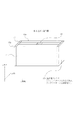
以下に、センシング系全体の説明を図2を用いてする。フェムト秒レーザ20から発せられた100fs(フェムト秒)程度のパルス幅を持つレーザ光をビームスプリッター21で二つに光路を分け、一方を低温成長させたGaAs(LT−GaAs)等で作製したバイアスされた光伝導アンテナ22aのギャップ部に照射してテラヘルツ波パルス27を発生させる(光伝導アンテナの背面には高抵抗Siなどでできた半球レンズを密着させる)。テラヘルツ波パルス27は放物面鏡23a、高抵抗Si(例えば10kΩcm)などで作られた半円筒レンズ24aを経て、平行平板導波路10の第一端から平行平板導波路10に結合する。テラヘルツ波パルスは平行平板導波路10中の空隙13中に導入された試料(図示せず)と相互作用した後、平行平板導波路10の第二端から半円筒レンズ24b、放物面鏡23bを経て光伝導アンテナ22bに到達する。一方、ビームスプリッター21で分けられたレーザ光のもう一方は、時間遅延器28、ミラー25などを経て光伝導アンテナ22bにテラヘルツ波パルスと同時に到達する。このとき時間遅延器28を用いて、時間遅延器28を経て光伝導アンテナ22bに到達したレーザ光と、平行平板導波路10を経て光伝導アンテナ22bに到達したテラヘルツ波パルスが到着するタイミングをずらすことで、テラヘルツ波パルスの波形が求められる。時間遅延器28を経たフェムト秒レーザ光が光伝導アンテナ22bに照射されると、フェムト秒レーザのパルス時間幅と光伝導アンテナ22bを構成する半導体膜のキャリア寿命に応じた時間だけ、光伝導アンテナ22bに電流が流れる。このときの電流の大きさは、光伝導アンテナ22bに入射するテラヘルツ波27の電場振幅の大きさを反映したものであることから、光伝導アンテナに流れる電流を計測することでテラヘルツ波パルス27の波形が得られ、これをフーリエ変換することでテラヘルツ波パルス27のスペクトルが得られる。
Hereinafter, the entire sensing system will be described with reference to FIG. A laser beam emitted from the
平行平板導波路はTEMモードで電磁波を伝搬できる。ゆえに空隙13に試料が存在しないときは、テラヘルツ波パルス27は平行平板導波路10の前後でパルス波形の形状を変えることなく平行平板導波路10を伝搬する。すなわち空隙13に試料が存在しない時は、平行平板導波路10に入射する前のテラヘルツ波パルス27の波形と、平行平板導波路10を透過したあとのテラヘルツ波パルス27の波形はほぼ相似である。
The parallel plate waveguide can propagate electromagnetic waves in the TEM mode. Therefore, when there is no sample in the
空隙13はx方向に50μm程度と十分薄いので、水などテラヘルツ波をよく吸収する試料が空隙13を満たしていても、平行平板導波路10を伝搬するテラヘルツ波は吸収し尽くされずに空隙13を透過することが出来る。
Since the
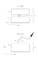
次に、本実施例における計測の一例を、図3を用いて具体的に述べる。図3は、本発明の実施例によって得られるテラヘルツ波のスペクトルを模式的に表したものである。まず、図1における空隙13に流動性試料を導入していない状態で、平行平板導波路10を透過するテラヘルツ波の波形を記録し、フーリエ変換してパワースペクトル30を求める。次に流動性試料を図1における空隙13に導入した上で、平行平板導波路10を透過したテラヘルツ波の波形を記録し、フーリエ変換したパワースペクトル31を求める。パワースペクトル31と30の比を求めることで、流動性試料のテラヘルツ波に対する吸収スペクトル32が求められる。
Next, an example of measurement in the present embodiment will be specifically described with reference to FIG. FIG. 3 schematically shows the spectrum of the terahertz wave obtained by the embodiment of the present invention. First, the waveform of the terahertz wave that passes through the
この方法では、空隙13の容積が十分小さく、必要とする試料は微量であるので、高価な試料(例えば抗体を含む溶液)を検査する上で有利である。
In this method, the volume of the
またここでテラヘルツ波パルス発生方法として光伝導アンテナによる方法を挙げたが、他の方法(例えば非線形結晶にフェムト秒レーザを照射する方法や、パラメトリック発振を利用した方法)を用いても良い。また、検出方法も、例えば電気光学結晶を用いた公知の方法などを用いても良い。 Although a method using a photoconductive antenna has been described here as a method for generating a terahertz wave pulse, other methods (for example, a method of irradiating a non-linear crystal with a femtosecond laser or a method using parametric oscillation) may be used. As a detection method, for example, a known method using an electro-optic crystal may be used.
本発明による第2の実施例は、図4に示すように、光伝導アンテナ33a、33bを平行平板導波路10の両端に設けることである。ただし、光伝導アンテナ33a、33bには高抵抗Siなどでできた半球レンズ等は密着させない。この場合、テラヘルツ波空間伝搬光学系の光軸調整が不要になり、系の小型化が図れる。
A second embodiment according to the present invention is to provide
光伝導アンテナ33a、33bは、典型的にはy方向とz方向に数ミリから1センチ程度の大きさの基板を持つ。金属板11a、11b、およびポリスチレン板12、空隙13の典型的な大きさは、実施例1と同じであるが、金属板11a、11bのy方向の長さ(厚さ)を5ミリ程度以上にすることで、光伝導アンテナ22a、22bを平行平板導波路10の両端に設けることを可能にする。
The
または図5のように、平行平板導波路10の各々の端面に光伝導アンテナ33a、および電気光学効果を持つ物質であるEO結晶34(例えばZnTe)を設けてもよい。この場合、フェムト秒レーザを光伝導アンテナ33aに照射することによって発生したテラヘルツ波が空隙13を透過した後EO結晶34に到達し、到達したテラヘルツ波の電波の振幅に応じてEO結晶34のレーザ光に対する反射率が変化することでテラヘルツ波の振幅を求めるという公知の技術を用いてテラヘルツ波を検出する。
Alternatively, as shown in FIG. 5, a
また平行平板導波路10の一端に、光伝導素子33aの変わりにDAST結晶やInPなどの非線形光学結晶を設置してもよい。この場合、フェムト秒レーザを直接照射することでテラヘルツが発生する。
Further, a nonlinear optical crystal such as DAST crystal or InP may be installed at one end of the
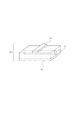
本発明第3の実施例を、図6に示し以下に説明する。平行平板導波路10を構成する金属板11a、11bの間に、ポリスチレンなどテラヘルツ波に対し吸収・損失および分散が小さい材料で出来た中空部材40を挟んだ構造である。この構造では、例えば中空部材40の先にチューブ41を接続し、チューブ41の先に注射針42を接続することで、人体から血液を採取と同時に導波路中へ導き、血液のテラヘルツ透過スペクトルを容易に得ることができる。
A third embodiment of the present invention is shown in FIG. 6 and will be described below. In this structure, a
本実施例では、流動性試料の採取と試料の計測・感知・分析を連続して行なうことができる。 In this embodiment, it is possible to continuously collect a fluid sample and measure, sense, and analyze the sample.
本発明による第4の実施例は、平行平板導波路の替わりに断面が方形または円形の導波管を用いたものである。図7に示したように、断面が方形の導波管中50に流動性試料導入のための中空部材40を設ける。方形導波管の断面の典型的な大きさは、x方向、y方向ともに100μmから200μmである。このような導波管を用いると、平行平板導波路に比べ小型化が図れる点で有利である。
The fourth embodiment according to the present invention uses a waveguide having a square or circular cross section instead of a parallel plate waveguide. As shown in FIG. 7, a
また、伝送線路において信号線とグラウンドの間に流動性試料を導入できる空隙を設けてもよい。図8のように、伝送線路60(図の例ではマイクロストリップライン)の信号線61とグラウンド62の間に流路63を設けたものである。伝送線路中に流路を設けることで、同一基板上に試料導入流路とテラヘルツ導波部分(伝送線路)を一体化して作製することが出来、更なる小型化が図れる。
Moreover, you may provide the space | gap which can introduce | transduce a fluid sample between a signal wire | line and ground in a transmission line. As shown in FIG. 8, a flow path 63 is provided between a
本発明による第5の実施例を、図9に示しながら以下に説明する。実施例1に示したような、空隙13を持った平行平板導波路10において、空隙13の一部にフィルタ14を設ける。空隙13の一端でフィルタ14が設置された側を空隙13の第一端とし、第一端の反対の端を第二端とする。例えば体液中に含まれるある種のたんぱく質をセンシングする場合、水を透過し前記のある種のたんぱく質を透過しないフィルタ(例えば半透膜)を設置する。第二端より空隙13中に体液を流しつづけることで、空隙13中における前記ある種のたんぱく質の濃度は上昇し、前記ある種のたんぱく質の透過スペクトルを高感度に精度よく測定することができる。
A fifth embodiment according to the present invention will be described below with reference to FIG. In the
この方法では、試料の高濃度化とセンシングが同一部分でできるため、試料の移し変えなどの手間が省ける。 In this method, the concentration of the sample can be increased and sensing can be performed in the same part, so that it is possible to save the trouble of transferring the sample.
本発明による第6の実施例を、図10に示しながら以下に説明する。実施例1に示したような空隙13を持った平行平板導波路10において、空隙13の内側に溶液中の特定な物質と特異的に結合もしくは吸着する物質15(例えばビオチン)を施す。前記物質15と特異的に結合する物質16(例えばアビジン)を含む溶液を空隙13に流す。水溶液中の前記物質16が空隙13の内側に施された前記物質15に結合し、テラヘルツ波の周波数領域における前記物質15の複素誘電率、吸収スペクトルが変化することを利用して物質のセンシングを高感度に行うことができる。この実施例の方法では、特定の物質のセンシングを高感度に行うことができるほか、透過テラヘルツ波のスペクトルから物質15に非特異的に吸着する物質と特異的に吸着する物質を、区別することも可能である。
A sixth embodiment according to the present invention will be described below with reference to FIG. In the
10 平行平板導波路
11a,b 金属板
12 ポリスチレン板
13 空隙
14 フィルタ
15 溶液中の物質と特異的に結合もしくは吸着する物質
16 水溶液中にあり、物質15と特異的に結合もしくは吸着する物質
20 フェムト秒レーザ
21 ビームスプリッター
22a,b 光伝導アンテナ
23a.b 放物面鏡
24a,b 半円筒レンズ
25 ミラー
26 時間遅延器
27 テラヘルツ波パルス
30 空隙に試料がないときのテラヘルツ波スペクトル
31 空隙に試料があるときのテラヘルツ波スペクトル
32 空隙に試料があるときとないときのテラヘルツ波スペクトルの比
33a,b 光伝導アンテナ
34 EO結晶
40 中空部材
41 チューブ
42 注射針
50 方形導波管
60 伝送線路
61 信号線
62 グラウンド
63 流路
DESCRIPTION OF
Claims (2)
前記テラヘルツ波を伝送するための金属導波管、金属平行平板導波路または伝送線路で構成されている伝送路と、
前記伝送路を伝搬してきたテラヘルツ波を検出するための検出手段とを備え、前記伝送路をテラヘルツ波が伝搬する際に、前記伝送路でテラヘルツ波が分布する領域の一部に、前記被測定対象物を配置するための通路を有し、
前記通路内に配置される前記被測定対象物を透過したテラヘルツ波を前記検出手段で検出し、前記通路に前記被測定対象物を導く注射針を備えることを特徴とする装置。 An apparatus for detecting a terahertz wave transmitted through an object to be measured, the generating means for generating the terahertz wave;
A transmission line composed of a metal waveguide, a metal parallel plate waveguide or a transmission line for transmitting the terahertz wave;
And a detection means for detecting a terahertz wave propagated through the transmission path, the transmission path when the terahertz wave is propagated, in a part of the region terahertz wave in the transmission line is distributed, the measured Having a passage for placing the object;
Wherein disposed in the passageway to detect a terahertz wave transmitted through the object to be measured by the detection means and Rukoto includes a needle for guiding the object to be measured in the channel device.
Priority Applications (5)
| Application Number | Priority Date | Filing Date | Title |
|---|---|---|---|
| JP2004376370A JP4154388B2 (en) | 2004-12-27 | 2004-12-27 | Detection device for detecting the state of electromagnetic waves transmitted through an object |
| CN2005800447315A CN101088004B (en) | 2004-12-27 | 2005-12-21 | Detection apparatus for detecting electromagnetic wave passed through object |
| EP05844596A EP1834170A4 (en) | 2004-12-27 | 2005-12-21 | Detection apparatus for detecting electromagnetic wave passed through object |
| PCT/JP2005/024017 WO2006070852A1 (en) | 2004-12-27 | 2005-12-21 | Detection apparatus for detecting electromagnetic wave passed through object |
| US10/584,800 US8039801B2 (en) | 2004-12-27 | 2005-12-21 | Detection apparatus for detecting electromagnetic wave passed through object |
Applications Claiming Priority (1)
| Application Number | Priority Date | Filing Date | Title |
|---|---|---|---|
| JP2004376370A JP4154388B2 (en) | 2004-12-27 | 2004-12-27 | Detection device for detecting the state of electromagnetic waves transmitted through an object |
Publications (3)
| Publication Number | Publication Date |
|---|---|
| JP2006184078A JP2006184078A (en) | 2006-07-13 |
| JP2006184078A5 JP2006184078A5 (en) | 2006-08-24 |
| JP4154388B2 true JP4154388B2 (en) | 2008-09-24 |
Family
ID=36614963
Family Applications (1)
| Application Number | Title | Priority Date | Filing Date |
|---|---|---|---|
| JP2004376370A Expired - Fee Related JP4154388B2 (en) | 2004-12-27 | 2004-12-27 | Detection device for detecting the state of electromagnetic waves transmitted through an object |
Country Status (5)
| Country | Link |
|---|---|
| US (1) | US8039801B2 (en) |
| EP (1) | EP1834170A4 (en) |
| JP (1) | JP4154388B2 (en) |
| CN (1) | CN101088004B (en) |
| WO (1) | WO2006070852A1 (en) |
Cited By (1)
| Publication number | Priority date | Publication date | Assignee | Title |
|---|---|---|---|---|
| US9553370B2 (en) | 2013-03-15 | 2017-01-24 | Nitto Denko Corporation | Antenna module and method for manufacturing the same |
Families Citing this family (26)
| Publication number | Priority date | Publication date | Assignee | Title |
|---|---|---|---|---|
| JP4620959B2 (en) * | 2004-03-26 | 2011-01-26 | キヤノン株式会社 | Biological information monitor device |
| JP4721416B2 (en) * | 2005-09-05 | 2011-07-13 | キヤノン株式会社 | Sample testing device and sample testing apparatus |
| US7532015B2 (en) | 2005-12-14 | 2009-05-12 | Agilent Technologies, Inc. | Microwave spectroscopy probe |
| US8455255B2 (en) | 2006-06-08 | 2013-06-04 | The University Of Tokushima | Method for production of novel nano silica particle and use of the nano silica particle |
| EP1935337A1 (en) * | 2006-12-21 | 2008-06-25 | Nederlandse Organisatie voor toegepast- natuurwetenschappelijk onderzoek TNO | An electromagnetic imaging system, a method and a computer program product |
| JP4871176B2 (en) | 2007-03-13 | 2012-02-08 | 浜松ホトニクス株式会社 | Total reflection terahertz wave measuring device |
| JP4800244B2 (en) * | 2007-03-13 | 2011-10-26 | 浜松ホトニクス株式会社 | Terahertz wave measuring device |
| JP5063325B2 (en) * | 2007-12-14 | 2012-10-31 | 独立行政法人理化学研究所 | Carrier concentration measuring apparatus and carrier concentration measuring method |
| GB2455722A (en) * | 2007-12-18 | 2009-06-24 | Hong Siang Tan | A spaced plate waveguide probe for dielectric measurement of biological tissue |
| EP2273254A4 (en) * | 2008-04-30 | 2014-02-26 | Hamamatsu Photonics Kk | Total reflection terahertz wave measurement device |
| US8259022B2 (en) * | 2008-05-02 | 2012-09-04 | William Marsh Rice University | Ultra low loss waveguide for broadband Terahertz radiation |
| JP2009288047A (en) * | 2008-05-29 | 2009-12-10 | Epson Toyocom Corp | Liquid cell for terahertz spectroscopic analysis and method for manufacturing liquid cell for terahertz spectroscopic analysis |
| US8309925B2 (en) * | 2009-09-17 | 2012-11-13 | William Marsh Rice University | Resonant cavity integrated into a waveguide for terahertz sensing |
| JP5521245B2 (en) * | 2010-02-03 | 2014-06-11 | 独立行政法人情報通信研究機構 | Recorded information reading device |
| WO2012093615A1 (en) | 2011-01-08 | 2012-07-12 | Canon Kabushiki Kaisha | Tomography apparatus and electromagnetic pulse transmitting apparatus |
| CN102097685A (en) * | 2011-01-15 | 2011-06-15 | 广东通宇通讯股份有限公司 | Parallel plate antenna based on Fabry resonant cavity principle |
| JP2012185151A (en) * | 2011-02-17 | 2012-09-27 | Arkray Inc | Terahertz wave characteristic measuring method, substance detection method, measuring tool, terahertz wave characteristic measuring device and substance detection device |
| JP6034616B2 (en) * | 2011-09-09 | 2016-11-30 | キヤノン株式会社 | Waveguide, manufacturing method thereof, and electromagnetic wave analyzer |
| JP5957294B2 (en) | 2012-05-29 | 2016-07-27 | 浜松ホトニクス株式会社 | Prism member, terahertz wave spectrometer, and terahertz wave spectrometer |
| US9772276B2 (en) | 2014-05-14 | 2017-09-26 | Konica Minolta, Inc. | Detection device and production method for same |
| US11255768B2 (en) * | 2014-06-25 | 2022-02-22 | Halliburton Energy Services, Inc. | In situ evaluation of filter parameters with opticoanalytical devices |
| KR101644799B1 (en) * | 2015-01-30 | 2016-08-02 | 한국해양대학교 산학협력단 | Terahertz Parallel-Plate Waveguide Sensor |
| EP3220113B1 (en) * | 2016-03-16 | 2019-05-01 | Centre National de la Recherche Scientifique - CNRS - | Optomechanical transducer for terahertz electromagnetic waves |
| KR102133543B1 (en) * | 2018-09-20 | 2020-07-21 | 홍익대학교 산학협력단 | Apparatus and method for analyzing metal-insulator-metal waveguide in tera hertz band |
| CN113088565B (en) * | 2021-04-26 | 2023-07-14 | 中国人民解放军陆军军医大学第一附属医院 | Terahertz chip for rapidly detecting microRNA and detection method thereof |
| CN115133246A (en) * | 2022-08-01 | 2022-09-30 | 四川太赫兹通信有限公司 | Terahertz integrated waveguide cavity, waveguide structure, radiometer system and electronic equipment |
Family Cites Families (20)
| Publication number | Priority date | Publication date | Assignee | Title |
|---|---|---|---|---|
| US3103627A (en) | 1960-05-18 | 1963-09-10 | Polarad Electronics Corp | Microwave transmission molecular identification system employing wave propagation mode detectors |
| GB1327452A (en) | 1970-07-08 | 1973-08-22 | Rank Organisation Ltd | Waveguides |
| US4029416A (en) * | 1973-11-15 | 1977-06-14 | Hawes Roland C | Sample-background-signal autocancellation in fluid-sample analyzers |
| US4134785A (en) * | 1977-04-13 | 1979-01-16 | Western Electric Company, Inc. | Real-time analysis and control of melt-chemistry in crystal growing operations |
| JP2839560B2 (en) * | 1989-07-10 | 1998-12-16 | 株式会社日立製作所 | Particle suspension mixing device, particle suspension mixing method, and particle measuring device |
| DE69132254T2 (en) | 1990-03-23 | 2000-10-26 | Commw Scient Ind Res Org | DETERMINATION OF CARBON IN FLIGHT ASH |
| US5363052A (en) | 1993-02-16 | 1994-11-08 | Solid State Farms, Inc. | Permittivity spectroscopy apparatus and method |
| US5521384A (en) * | 1995-05-12 | 1996-05-28 | Perstorp Analytical, Inc. | Flow cell |
| CN1162121A (en) * | 1995-12-21 | 1997-10-15 | 欧洲Emc服务汉森博士有限公司 | Method for generating and receiving electromagnetic wave for detection, and apparatus thereof |
| WO2000050859A1 (en) * | 1999-02-23 | 2000-08-31 | Teraprobe Limited | Method and apparatus for terahertz imaging |
| US6465776B1 (en) * | 2000-06-02 | 2002-10-15 | Board Of Regents, The University Of Texas System | Mass spectrometer apparatus for analyzing multiple fluid samples concurrently |
| WO2002066983A2 (en) * | 2001-02-01 | 2002-08-29 | Signature Bioscience, Inc. | Bioassay device for detecting molecular events |
| IL143980A0 (en) * | 2001-06-25 | 2002-04-21 | Imarad Imaging Systems Ltd | Three dimensional radiation detection |
| JP4517679B2 (en) | 2003-03-31 | 2010-08-04 | Tdk株式会社 | Measuring device for complex permittivity of dielectrics |
| US7057250B2 (en) * | 2003-04-09 | 2006-06-06 | University Of Delaware | Terahertz frequency band wavelength selector |
| JP4183546B2 (en) | 2003-04-11 | 2008-11-19 | 独立行政法人理化学研究所 | Terahertz optical system |
| JP4620959B2 (en) | 2004-03-26 | 2011-01-26 | キヤノン株式会社 | Biological information monitor device |
| JP4365762B2 (en) * | 2004-09-30 | 2009-11-18 | 株式会社日立製作所 | Nuclear medicine diagnostic apparatus and method for cooling nuclear medicine diagnostic apparatus |
| JP3852850B2 (en) * | 2004-10-25 | 2006-12-06 | 株式会社日立製作所 | Radiation imaging apparatus and nuclear medicine diagnostic apparatus |
| JP3858044B1 (en) * | 2005-09-09 | 2006-12-13 | 株式会社日立製作所 | Radiation detection module, printed circuit board, and positron emission tomography apparatus |
-
2004
- 2004-12-27 JP JP2004376370A patent/JP4154388B2/en not_active Expired - Fee Related
-
2005
- 2005-12-21 CN CN2005800447315A patent/CN101088004B/en not_active Expired - Fee Related
- 2005-12-21 US US10/584,800 patent/US8039801B2/en not_active Expired - Fee Related
- 2005-12-21 EP EP05844596A patent/EP1834170A4/en not_active Ceased
- 2005-12-21 WO PCT/JP2005/024017 patent/WO2006070852A1/en active Application Filing
Cited By (1)
| Publication number | Priority date | Publication date | Assignee | Title |
|---|---|---|---|---|
| US9553370B2 (en) | 2013-03-15 | 2017-01-24 | Nitto Denko Corporation | Antenna module and method for manufacturing the same |
Also Published As
| Publication number | Publication date |
|---|---|
| US8039801B2 (en) | 2011-10-18 |
| CN101088004B (en) | 2011-06-15 |
| US20090134329A1 (en) | 2009-05-28 |
| WO2006070852A1 (en) | 2006-07-06 |
| EP1834170A1 (en) | 2007-09-19 |
| EP1834170A4 (en) | 2008-01-16 |
| JP2006184078A (en) | 2006-07-13 |
| CN101088004A (en) | 2007-12-12 |
Similar Documents
| Publication | Publication Date | Title |
|---|---|---|
| JP4154388B2 (en) | Detection device for detecting the state of electromagnetic waves transmitted through an object | |
| US7633299B2 (en) | Inspection apparatus using terahertz wave | |
| JP4546326B2 (en) | Sensing device | |
| EP2015054B1 (en) | Terahertz Time-Domain Spectroscopy in Attenuated-Total-Reflection | |
| US7271914B2 (en) | Biomolecular sensor system utilizing a transverse propagation wave of surface plasmon resonance (SPR) | |
| US7781737B2 (en) | Apparatus and methods for oil-water-gas analysis using terahertz radiation | |
| US7671995B2 (en) | Method for improving surface plasmon resonance by using conducting metal oxide as adhesive layer | |
| US7812955B2 (en) | Sample analysis apparatus and analysis method | |
| US8981303B2 (en) | Sensor device | |
| JPWO2008026523A1 (en) | Near-field light measurement method and near-field light measurement device | |
| KR20080042926A (en) | Terahertz waveguide device and detection method using the same | |
| CN101539017A (en) | Device and method for analyzing oil-water-gas by using terahertz radiation | |
| US10324034B2 (en) | Self-referencing localized plasmon resonance sensing device and system thereof | |
| US10107771B2 (en) | Sensor for dielectric spectroscopy of a sample | |
| CN207850914U (en) | A kind of detection device and detecting system based on THz wave | |
| Dobroiu et al. | Monolithic Fabry-Perot resonator for the measurement of optical constants in the terahertz range | |
| JP2002357544A (en) | Measuring apparatus | |
| JP2019109117A (en) | Carbonate mineral analysis method | |
| CN115461608A (en) | Multi-reflection liquid silicon-immersed micro flow channel measuring device and method | |
| Collier | Microfluidic and terahertz technologies for integrated spectroscopic systems | |
| Kaushik | Characterizing and mitigating scattering effects in terahertz time domain spectroscopy measurements. | |
| Isaac et al. | Terahertz surface plasmons for subwavelength sensing and spectroscopy | |
| JPS61137048A (en) | Apparatus for measuring scattering of light | |
| JPS61137044A (en) | Apparatus for measuring light scattering | |
| JPS61137045A (en) | Apparatus for measuring light scattering |
Legal Events
| Date | Code | Title | Description |
|---|---|---|---|
| A521 | Written amendment |
Free format text: JAPANESE INTERMEDIATE CODE: A523 Effective date: 20060630 |
|
| A621 | Written request for application examination |
Free format text: JAPANESE INTERMEDIATE CODE: A621 Effective date: 20060630 |
|
| A131 | Notification of reasons for refusal |
Free format text: JAPANESE INTERMEDIATE CODE: A131 Effective date: 20071113 |
|
| A521 | Written amendment |
Free format text: JAPANESE INTERMEDIATE CODE: A523 Effective date: 20080115 |
|
| A131 | Notification of reasons for refusal |
Free format text: JAPANESE INTERMEDIATE CODE: A131 Effective date: 20080401 |
|
| A521 | Written amendment |
Free format text: JAPANESE INTERMEDIATE CODE: A523 Effective date: 20080527 |
|
| TRDD | Decision of grant or rejection written | ||
| A01 | Written decision to grant a patent or to grant a registration (utility model) |
Free format text: JAPANESE INTERMEDIATE CODE: A01 Effective date: 20080624 |
|
| A01 | Written decision to grant a patent or to grant a registration (utility model) |
Free format text: JAPANESE INTERMEDIATE CODE: A01 |
|
| A61 | First payment of annual fees (during grant procedure) |
Free format text: JAPANESE INTERMEDIATE CODE: A61 Effective date: 20080707 |
|
| R150 | Certificate of patent or registration of utility model |
Free format text: JAPANESE INTERMEDIATE CODE: R150 |
|
| FPAY | Renewal fee payment (event date is renewal date of database) |
Free format text: PAYMENT UNTIL: 20110711 Year of fee payment: 3 |
|
| FPAY | Renewal fee payment (event date is renewal date of database) |
Free format text: PAYMENT UNTIL: 20120711 Year of fee payment: 4 |
|
| FPAY | Renewal fee payment (event date is renewal date of database) |
Free format text: PAYMENT UNTIL: 20120711 Year of fee payment: 4 |
|
| FPAY | Renewal fee payment (event date is renewal date of database) |
Free format text: PAYMENT UNTIL: 20130711 Year of fee payment: 5 |
|
| LAPS | Cancellation because of no payment of annual fees |