JP4149236B2 - Golf ball and golf ball manufacturing method - Google Patents
Golf ball and golf ball manufacturing method Download PDFInfo
- Publication number
- JP4149236B2 JP4149236B2 JP2002315592A JP2002315592A JP4149236B2 JP 4149236 B2 JP4149236 B2 JP 4149236B2 JP 2002315592 A JP2002315592 A JP 2002315592A JP 2002315592 A JP2002315592 A JP 2002315592A JP 4149236 B2 JP4149236 B2 JP 4149236B2
- Authority
- JP
- Japan
- Prior art keywords
- golf ball
- less
- coating layer
- main body
- dimple
- Prior art date
- Legal status (The legal status is an assumption and is not a legal conclusion. Google has not performed a legal analysis and makes no representation as to the accuracy of the status listed.)
- Expired - Fee Related
Links
Images


Description
【0001】
【発明の属する技術分野】
本発明は、ゴルフボールに関する。詳細には、本発明は、ゴルフボールの空力特性の改良に関するものである。
【0002】
【従来の技術】
ゴルフボールは、その表面に多数のディンプルを備えている。ディンプルの役割は、ゴルフボール飛行時にゴルフボール周りの空気の流れを乱すことによって境界層の乱流遷移を促進し、乱流剥離を起こさせることにある(以下、「ディンプル効果」と称される)。乱流遷移の促進により空気のゴルフボールからの剥離点が後方にシフトし、抗力係数(Cd)が小さくなってゴルフボールの飛距離が増大する。飛行性能向上を意図したディンプルの改良が、種々提案されている。
【0003】
【特許文献1】
特開平10−234885号公報
【0004】
【発明が解決しようとする課題】
ゴルファーのゴルフボールに対する最大の関心事は、飛距離である。飛距離は、打撃時のゴルフボールの変形挙動と、飛行時の空力特性とに依存する。空力特性に最も影響を与えるのは、ディンプルである。前述のようにディンプルの改良が種々なされているが、ゴルファーは更なる飛距離の向上を望んでいる。ディンプル以外の観点からの、空力特性の改善が必要である。本発明の目的は、ゴルフボールの飛行性能を改善することにある。
【0005】
【課題を解決するための手段】
本発明に係るゴルフボールは、実質的に球状である本体と、この本体を被覆する塗装層とを備えている。この塗装層の表面の10点平均粗さRzは、0.006mm以上0.300mm以下である。この塗装層表面は、従来のゴルフボールの塗装層表面よりも粗い。この塗装層は、空力特性の向上に寄与する。このゴルフボールは、飛行性能に優れる。このゴルフボールが飛行性能に優れる理由は詳細には不明であるが、塗装層表面に形成された微小凹部が抗力を低減するためと推測される。
【0006】
好ましくは、ディンプルの総容積は270mm3以上370mm3以下である。このゴルフボールは、さらに優れた飛行性能を備える。
【0007】
他の発明に係るゴルフボールは、実質的に球状である本体と、この本体を被覆する塗装層とを備えている。この塗装層の表面は、高粗度領域と低粗度領域とに区分されている。高粗度領域における10点平均粗さRzは、0.006mm以上0.300mm以下である。低粗度領域における10点平均粗さRzは、0.006mm未満である。この塗装層により、ゴルフボールの空力的対称性が向上しうる。
【0008】
本発明に係るゴルフボール製造方法は、以下の工程を含む。
(1)実質的に球体である本体の表面に塗装層が形成される工程。
及び
(2)この塗装層の表面がブラスト処理される工程。
この製造方法により、飛行性能に優れたゴルフボールが得られうる。
【0009】
【発明の実施の形態】
以下、適宜図面が参照されつつ、好ましい実施形態に基づいて本発明が詳細に説明される。
【0010】
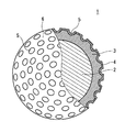
図1は、本発明の一実施形態に係るゴルフボール1が示された一部切り欠き断面図である。このゴルフボール1は、球状のコア2と、カバー3と、塗装層4とを備えている。ゴルフボール1の表面には、多数のディンプル5が形成されている。ゴルフボール1の表面のうちディンプル5以外の部分は、ランド6である。コア2とカバー3とは、本体を形成する。本体は、表面にディンプル5を備えているが、実質的に球体である。塗装層4は、本体を被覆している。
【0011】
このゴルフボール1の直径は、通常は40mmから45mm、さらには42mmから44mmである。米国ゴルフ協会(USGA)の規格が満たされる範囲で空気抵抗が低減されるという観点から、直径は42.67mm以上42.80mm以下が特に好ましい。このゴルフボール1の質量は、通常は40g以上50g以下、さらには44g以上47g以下である。米国ゴルフ協会の規格が満たされる範囲で慣性が高められるという観点から、質量は45.00g以上45.93g以下が特に好ましい。
【0012】
図2は、図1のゴルフボール1の一部が示された拡大断面図である。この図には、ディンプル5の最深部及びゴルフボール1の中心を通過する平面に沿った断面が画かれている。この図2から明らかなように、塗装層4は表面に微小な凹部7を多数備えている。この凹部7によって、表面の粗さが高められている。この凹部7は、ゴルフボール1が飛行する際の乱流遷移を促進し、抗力低減に寄与すると推測される。この凹部7により空力特性が向上し、ゴルフボール1の飛距離が増大する。
【0013】
前述のように、凹部7は塗装層4の表面に存在している。凹部7は、ディンプル5にもランド6にも存在する。凹部7は、カバー3にまでは至っていない。凹部7は、塗装層4及びカバー3が共に凹陥しているディンプル5とは明確に区別される。
【0014】
塗装層4の表面の10点平均粗さRzは、0.006mm以上0.300mm以下である。10点平均粗さRzが上記範囲未満であると、凹部7による空力特性の向上が不十分となることがある。この観点から、10点平均粗さRzは0.008mm以上がより好ましい。10点平均粗さRzが上記範囲を超えると、凹部7によってディンプル5の形状が損なわれ、ゴルフボール1の飛距離が不十分となることがある。この観点から、10点平均粗さRzは0.200mm以下がより好ましい。10点平均粗さRzは、「JIS B 0601」の規定に準拠して測定される。
【0015】
このゴルフボール1の製造では、まずコア2が成形される。次に、このコア2の周りにカバー3が成形される。カバー3の成形と同時に、ディンプル5が形成される。次に、カバー3の表面に塗料が塗布される。この塗料が乾燥することで、塗装層4が得られる。次に、この塗装層4の表面にブラスト処理が施される。ブラスト処理では、微小粒子が塗装層4に吹きつけられる。ブラスト処理により、塗装層4に凹部7が形成される。この凹部7により、塗装層4の表面粗さが高められる。
【0016】
ブラスト処理の粒子の材質は、特には制限がない。材質の具体例としては、アルミナ(ABRAX−Rの#60〜#180)及びガラス(#30〜#200)が挙げられる。粒子の平均直径は、10μm〜700μmが好ましい。ブラスト処理におけるエアー圧力は、490kPa〜785kPaが好ましい。
【0017】
凹部7の形成が、ブラスト処理以外の方法でなされてもよい。ブラスト処理以外の方法としては、研磨、切削、コテ当て等が挙げられる。
【0018】
図2において仮想線Tで示されているのは、ディンプル5の両端に共通の接線である。この仮想線Tとディンプル5の表面とに囲まれた部分の容積は、ディンプル5の容積である。ディンプル5の総容積は、270mm3以上370mm3以下が好ましい。総容積が上記範囲未満であると、ホップする弾道となることがある。この観点から、総容積は290mm3以上が特に好ましい。総容積が上記範囲を超えると、ドロップする弾道となるおそれがある。この観点から、総容積は350mm3以下が特に好ましい。
【0019】
ディンプル5の総面積が仮想球の表面積に占める比率は、表面積占有率と称される。表面積占有率は、70%以上90%以下が好ましい。表面積占有率が上記範囲未満であると、飛行中のゴルフボール1の揚力が不足するおそれがある。この観点から、表面積占有率は72%以上がより好ましく、75%以上が特に好ましい。表面積占有率が上記範囲を超えると、ホップする弾道となることがある。この観点から、表面積占有率は88%以下がより好ましく、86%以下が特に好ましい。ディンプル5の面積は、無限遠からゴルフボール1の中心を見た場合の、エッジラインに囲まれた領域の面積(すなわち平面形状の面積)である。
【0020】
個々のディンプル5の深さは、0.1mm以上0.6mm以下が好ましい。深さが上記範囲未満であると、ホップする弾道となることがある。この観点から、深さは0.12mm以上がより好ましく、0.14mm以上が特に好ましい。深さが上記範囲を超えると、ドロップする弾道となることがある。この観点から、深さは0.55mm以下がより好ましく、0.50mm以下が特に好ましい。深さが上記範囲に含まれるディンプル5の数がディンプル5の総数に占める比率は50%以上が好ましく、65%以上がより好ましく、80%以上が特に好ましい。深さは、仮想線Tからディンプル5の最深部までの距離である。
【0021】
ディンプル5の総数は、200個以上500個以下が好ましい。総数が上記範囲未満であると、ディンプル効果が得られにくい。この観点から、総数は230個以上がより好ましく、260個以上が特に好ましい。総数が上記範囲を超えると、ディンプル効果が得られにくい。この観点から、総数は470個以下がより好ましく、440個以下が特に好ましい。
【0022】
形成されるディンプル5は単一種類でもよく、複数種類であってもよい。円形ディンプル5に代えて、又は円形ディンプル5とともに、非円形ディンプル(平面形状が円でないディンプル)が形成されてもよい。
【0023】
図1に示されたゴルフボール1は、ツーピース構造であるが、マルチピースゴルフボール、糸巻きゴルフボール又はワンピースゴルフボールにおいても、塗装層4に凹部7が形成されるのが好ましい。
【0024】
図3は、本発明の他の実施形態に係るゴルフボール8が示された正面図である。図示されていないが、このゴルフボール8も、本体と塗装層とを備えている。このゴルフボール8の成形には、上型及び下型からなる成形型が用いられる。上型及び下型は、いずれも半球状のキャビティを備えている。成形時には、上型と下型とのパーティングラインからカバーの材料が流出し、バリが生じる。バリは、研削等の手段によって除去される。図3において仮想線Sで示されているのは、シームである。シームSは、成形型のパーティングラインに対応する。バリの除去の容易の観点から、シームSにはディンプル9が設けられていない。図3において符号Pで示されているのは、ポールである。
【0025】
図3において符号Bで示されている2本の仮想線は、塗装層の表面を高粗度領域Hと低粗度領域Lとに区画する線である。高粗度領域Hは、シームSに沿って帯状に延びている。高粗度領域H以外の領域が、低粗度領域Lである。低粗度領域Lは、2つに分かれている。低粗度領域Lには、ポールPが含まれる。図示されていないが、高粗度領域Hには、微小な凹部が多数形成されている。高粗度領域Hにおける10点平均粗さRzは、0.006mm以上0.300mm以下である。低粗度領域Lにおける10点平均粗さRzは、0.006mm未満である。このゴルフボール8は、ポールPの近傍にマスキングが施された状態でブラスト処理がなされることで得られうる。シームSの近傍のみが研磨されることで、ゴルフボール8が得られてもよい。
【0026】
ゴルフボール8の飛距離は、バックスピンの周速が最も速い大円の近傍における表面状態に大きく依存する。バックスピンの周速が最も速い大円がシームSと一致したとき、高粗度領域Hが飛距離向上に寄与する。前述のようにシームSにはディンプル9が存在しないので、このシームSが周速の最も速い大円と一致したときのディンプル効果は少ないが、これを高粗度領域Hに存在する凹部が補う。このゴルフボール8は、空力的対称性に優れる。
【0027】
高粗度領域HがシームSに沿って延びる必要はなく、低粗度領域LがポールPを含む必要もない。ディンプルパターン、製造上の誤差等が加味されて、高粗度領域H及び低粗度領域Lの位置が決定される。
【0028】
ゴルフボール8の仮想球面に占める高粗度領域Hの比率は、5%以上70%以下が好ましく、10%以上40%以下が特に好ましい。ゴルフボール8の仮想球面に占める高粗度領域Hの比率は、30%以上95%以下が好ましく、60%以上90%以下が特に好ましい。
【0029】
【実施例】
以下、実施例に基づいて本発明の効果が明らかにされるが、この実施例の記載に基づいて本発明が限定的に解釈されるべきではない。
【0030】
[実施例1]
ソリッドゴムからなり直径が38.4mmであるコアを金型に投入し、コアの周りにアイオノマー樹脂組成物を射出してカバー層を形成した。このカバー層の表面に塗装を施して塗料を乾燥させ、塗装層を得た。この塗装層の表面にブラスト処理を施し、実施例1のゴルフボールを得た。ブラスト処理のエアー圧力は、640kPaであった。ブラスト処理には、アルミナからなる粒子を用いた。粒子の平均直径は、330μmであった。このゴルフボールにおける塗装層の10点平均粗さは0.020mmであり、ディンプルの総容積は320mm3であった。
【0031】
[実施例2、3、6及び7]
ブラスト処理のエアー圧力及び粒子直径を異ならせて10点平均粗さRzを下記の表1に示される通りとした他は実施例1と同様にして、実施例2、3、6及び7のゴルフボールを得た。
【0032】
[実施例4及び5]
金型を変更してディンプルの総容積を下記の表1に示される通りとした他は実施例1と同様にして、実施例4及び5のゴルフボールを得た。
【0033】
[比較例1]
ブラスト処理を施さなかった他は実施例1と同様にして、比較例1のゴルフボールを得た。
【0034】
[飛距離テスト]
スイングマシン(ゴルフラボラトリー社製)に、5番アイアン(住友ゴム工業社の「XXIO I#5」、ロフト角度:26°、シャフト硬度:S)を装着した。ヘッド速度が41m/secとなる条件でゴルフボールを打撃し、弾道仰角及び飛距離(発射地点から落下地点までの距離)を測定した。弾道仰角は、弾道最高点と発射地点とを結ぶ直線と水平線とのなす角度である。20回の測定データの平均値が、下記の表1に示されている。
【0035】
【表1】

表1に示されるように、実施例のゴルフボールは比較例のゴルフボールよりも飛距離が大きい。この評価結果から、本発明の優位性は明らかである。
【0037】
【発明の効果】
以上説明されたように、本発明のゴルフボールは飛行性能に優れる。このゴルフボールは、これを打撃するゴルファーに爽快感を与え、かつスコアの向上に寄与する。
【図面の簡単な説明】
【図1】図1は、本発明の一実施形態に係るゴルフボールが示された一部切り欠き断面図である。
【図2】図2は、図1のゴルフボール1の一部が示された拡大断面図である。
【図3】図3は、本発明の他の実施形態に係るゴルフボールが示された正面図である。
【符号の説明】
1、8・・・ゴルフボール
2・・・コア
3・・・カバー
4・・・塗装層
5、9・・・ディンプル
6・・・ランド
7・・・凹部
S・・・シーム
P・・・ポール
H・・・高粗度領域
L・・・低粗度領域[0001]
BACKGROUND OF THE INVENTION
The present invention relates to a golf ball. Specifically, the present invention relates to an improvement in the aerodynamic characteristics of a golf ball.
[0002]
[Prior art]
The golf ball has a large number of dimples on its surface. The role of dimples is to promote turbulent flow transition in the boundary layer by disturbing the air flow around the golf ball during flight, thereby causing turbulent separation (hereinafter referred to as “dimple effect”). ). By promoting the turbulent transition, the separation point of air from the golf ball is shifted backward, the drag coefficient (Cd) is decreased, and the flight distance of the golf ball is increased. Various dimple improvements intended to improve flight performance have been proposed.
[0003]
[Patent Document 1]
[Patent Document 1] Japanese Patent Laid-Open No. 10-234885
[Problems to be solved by the invention]
A golfer's greatest concern with a golf ball is flight distance. The flight distance depends on the deformation behavior of the golf ball at the time of hitting and the aerodynamic characteristics at the time of flight. The dimple has the most influence on the aerodynamic characteristics. As described above, the dimples have been improved variously, but the golfer wants to further improve the flight distance. It is necessary to improve the aerodynamic characteristics from a viewpoint other than dimples. An object of the present invention is to improve the flight performance of a golf ball.
[0005]
[Means for Solving the Problems]
The golf ball according to the present invention includes a substantially spherical main body and a coating layer covering the main body. The 10-point average roughness Rz of the surface of this coating layer is 0.006 mm or more and 0.300 mm or less. The surface of the paint layer is rougher than the paint layer surface of a conventional golf ball. This coating layer contributes to the improvement of aerodynamic characteristics. This golf ball is excellent in flight performance. The reason why this golf ball is excellent in flight performance is unknown in detail, but it is presumed that minute concave portions formed on the surface of the coating layer reduce drag.
[0006]
Preferably, the total volume of the dimples is 270 mm 3 or more and 370 mm 3 or less. This golf ball has further excellent flight performance.
[0007]
A golf ball according to another invention includes a substantially spherical main body and a coating layer that covers the main body. The surface of the coating layer is divided into a high roughness region and a low roughness region. The 10-point average roughness Rz in the high roughness region is 0.006 mm or more and 0.300 mm or less. The 10-point average roughness Rz in the low roughness region is less than 0.006 mm. This paint layer can improve the aerodynamic symmetry of the golf ball.
[0008]
The golf ball manufacturing method according to the present invention includes the following steps.
(1) A step in which a coating layer is formed on the surface of a main body that is substantially a sphere.
And (2) a step of blasting the surface of the coating layer.
With this manufacturing method, a golf ball having excellent flight performance can be obtained.
[0009]
DETAILED DESCRIPTION OF THE INVENTION
Hereinafter, the present invention will be described in detail based on preferred embodiments with appropriate reference to the drawings.
[0010]
FIG. 1 is a partially cutaway sectional view showing a
[0011]
The diameter of the
[0012]
FIG. 2 is an enlarged cross-sectional view showing a part of the
[0013]
As described above, the
[0014]
The 10-point average roughness Rz of the surface of the coating layer 4 is 0.006 mm or more and 0.300 mm or less. When the 10-point average roughness Rz is less than the above range, the improvement of the aerodynamic characteristics by the
[0015]
In manufacturing the
[0016]
The material of the blasting particles is not particularly limited. Specific examples of the material include alumina (# 60 to # 180 of ABRAX-R) and glass (# 30 to # 200). The average diameter of the particles is preferably 10 μm to 700 μm. The air pressure in the blast treatment is preferably 490 kPa to 785 kPa.
[0017]
The formation of the
[0018]
In FIG. 2, a tangent line common to both ends of the
[0019]
The ratio of the total area of the
[0020]
The depth of each
[0021]
The total number of
[0022]
The
[0023]
Although the
[0024]
FIG. 3 is a front view showing a golf ball 8 according to another embodiment of the present invention. Although not shown, this golf ball 8 also includes a main body and a paint layer. For molding the golf ball 8, a mold composed of an upper mold and a lower mold is used. Each of the upper mold and the lower mold includes a hemispherical cavity. At the time of molding, the cover material flows out from the parting line between the upper mold and the lower mold, and burrs are generated. The burrs are removed by means such as grinding. In FIG. 3, what is indicated by a virtual line S is a seam. The seam S corresponds to the parting line of the mold. From the viewpoint of easy removal of burrs, the
[0025]
Two imaginary lines indicated by reference sign B in FIG. 3 are lines that divide the surface of the coating layer into a high roughness region H and a low roughness region L. The high roughness region H extends in a strip shape along the seam S. A region other than the high roughness region H is the low roughness region L. The low roughness region L is divided into two. The low roughness region L includes a pole P. Although not shown, in the high roughness region H, a large number of minute recesses are formed. The 10-point average roughness Rz in the high roughness region H is 0.006 mm or more and 0.300 mm or less. The 10-point average roughness Rz in the low roughness region L is less than 0.006 mm. The golf ball 8 can be obtained by performing a blasting process in a state where masking is performed in the vicinity of the pole P. The golf ball 8 may be obtained by polishing only the vicinity of the seam S.
[0026]
The flight distance of the golf ball 8 greatly depends on the surface state in the vicinity of the great circle with the fastest peripheral speed of backspin. When the great circle with the fastest peripheral speed of backspin coincides with the seam S, the high roughness region H contributes to the flight distance improvement. As described above, since the
[0027]
The high roughness region H does not need to extend along the seam S, and the low roughness region L does not need to include the pole P. The positions of the high roughness region H and the low roughness region L are determined in consideration of dimple patterns, manufacturing errors, and the like.
[0028]
The ratio of the high roughness region H to the phantom spherical surface of the golf ball 8 is preferably 5% to 70%, and particularly preferably 10% to 40%. The ratio of the high roughness region H to the phantom spherical surface of the golf ball 8 is preferably 30% to 95%, particularly preferably 60% to 90%.
[0029]
【Example】
Hereinafter, although the effect of the present invention will be clarified based on examples, the present invention should not be construed limitedly based on the description of the examples.
[0030]
[Example 1]
A core made of solid rubber and having a diameter of 38.4 mm was put into a mold, and an ionomer resin composition was injected around the core to form a cover layer. The surface of the cover layer was painted and the paint was dried to obtain a painted layer. The surface of this paint layer was blasted to obtain a golf ball of Example 1. The air pressure for blasting was 640 kPa. For blasting, particles made of alumina were used. The average diameter of the particles was 330 μm. The 10-point average roughness of the paint layer in this golf ball was 0.020 mm, and the total volume of the dimples was 320 mm 3 .
[0031]
[Examples 2, 3, 6 and 7]
Golf of Examples 2, 3, 6 and 7 in the same manner as in Example 1 except that the air pressure and particle diameter of the blast treatment were changed so that the 10-point average roughness Rz was as shown in Table 1 below. I got the ball.
[0032]
[Examples 4 and 5]
Golf balls of Examples 4 and 5 were obtained in the same manner as in Example 1 except that the mold was changed so that the total volume of the dimples was as shown in Table 1 below.
[0033]
[Comparative Example 1]
A golf ball of Comparative Example 1 was obtained in the same manner as in Example 1 except that the blast treatment was not performed.
[0034]
[Flight distance test]
A No. 5 iron (“
[0035]
[Table 1]
As shown in Table 1, the golf ball of the example has a greater flight distance than the golf ball of the comparative example. From this evaluation result, the superiority of the present invention is clear.
[0037]
【The invention's effect】
As described above, the golf ball of the present invention has excellent flight performance. This golf ball gives a refreshing feeling to a golfer who hits the golf ball and contributes to an improvement in score.
[Brief description of the drawings]
FIG. 1 is a partially cutaway sectional view showing a golf ball according to an embodiment of the present invention.
FIG. 2 is an enlarged cross-sectional view showing a part of the
FIG. 3 is a front view showing a golf ball according to another embodiment of the present invention.
[Explanation of symbols]
DESCRIPTION OF
Claims (4)
その表面に多数のディンプル及び多数の微小な凹部を備えており、
このディンプルがカバーに形成されており、
この凹部が塗装層に形成されており、かつこの凹部がカバーにまでは至っておらず、
この塗装層の表面の10点平均粗さRzが0.020mm以上0.100mm以下であるゴルフボール。A main body having a core and a cover, and a paint layer covering the main body;
It has a large number of dimples and a large number of minute recesses on its surface,
This dimple is formed on the cover,
This recess is formed in the paint layer, and this recess does not reach the cover,
A golf ball having a 10-point average roughness Rz of 0.020 mm to 0.100 mm on the surface of the coating layer.
Priority Applications (1)
| Application Number | Priority Date | Filing Date | Title |
|---|---|---|---|
| JP2002315592A JP4149236B2 (en) | 2002-10-30 | 2002-10-30 | Golf ball and golf ball manufacturing method |
Applications Claiming Priority (1)
| Application Number | Priority Date | Filing Date | Title |
|---|---|---|---|
| JP2002315592A JP4149236B2 (en) | 2002-10-30 | 2002-10-30 | Golf ball and golf ball manufacturing method |
Publications (2)
| Publication Number | Publication Date |
|---|---|
| JP2004147836A JP2004147836A (en) | 2004-05-27 |
| JP4149236B2 true JP4149236B2 (en) | 2008-09-10 |
Family
ID=32459544
Family Applications (1)
| Application Number | Title | Priority Date | Filing Date |
|---|---|---|---|
| JP2002315592A Expired - Fee Related JP4149236B2 (en) | 2002-10-30 | 2002-10-30 | Golf ball and golf ball manufacturing method |
Country Status (1)
| Country | Link |
|---|---|
| JP (1) | JP4149236B2 (en) |
Families Citing this family (26)
| Publication number | Priority date | Publication date | Assignee | Title |
|---|---|---|---|---|
| JP4754350B2 (en) * | 2005-12-28 | 2011-08-24 | Sriスポーツ株式会社 | Golf ball |
| JP4663568B2 (en) * | 2006-03-30 | 2011-04-06 | Sriスポーツ株式会社 | Golf ball |
| JP4756485B2 (en) * | 2006-04-13 | 2011-08-24 | Sriスポーツ株式会社 | Golf ball |
| JP4756486B2 (en) * | 2006-05-17 | 2011-08-24 | Sriスポーツ株式会社 | Golf ball |
| US9199133B2 (en) | 2009-09-30 | 2015-12-01 | Nike, Inc. | Golf ball having an aerodynamic coating including micro surface roughness |
| US9409064B2 (en) * | 2009-09-30 | 2016-08-09 | Nike, Inc. | Golf ball having an aerodynamic coating including micro surface roughness |
| US9259623B2 (en) * | 2009-09-30 | 2016-02-16 | Nike International, Ltd. | Golf ball having an aerodynamic coating including micro surface roughness |
| US9033826B2 (en) | 2009-09-30 | 2015-05-19 | Nike, Inc. | Golf ball having an aerodynamic coating including micro surface roughness |
| US9186557B2 (en) | 2009-09-30 | 2015-11-17 | Nike, Inc. | Golf ball having an aerodynamic coating including micro surface roughness |
| US9381404B2 (en) | 2009-09-30 | 2016-07-05 | Nike, Inc. | Golf ball having an increased moment of inertia |
| US9108085B2 (en) | 2009-09-30 | 2015-08-18 | Nike, Inc. | Golf ball having an aerodynamic coating including micro surface roughness |
| US20110077106A1 (en) * | 2009-09-30 | 2011-03-31 | Nike, Inc. | Golf Ball Having An Aerodynamic Coating |
| US9186558B2 (en) | 2009-09-30 | 2015-11-17 | Nike, Inc. | Golf ball having an aerodynamic coating including micro surface roughness |
| US9033825B2 (en) | 2009-09-30 | 2015-05-19 | Nike, Inc. | Golf ball having an aerodynamic coating including micro surface roughness |
| US8529375B2 (en) * | 2010-01-20 | 2013-09-10 | Nike, Inc. | Golf ball having increased moment of inertia |
| US9320942B2 (en) | 2010-01-20 | 2016-04-26 | Nike, Inc. | Golf ball with cover layer having zones of differing materials |
| US8602915B2 (en) * | 2010-11-01 | 2013-12-10 | Nike, Inc. | Golf ball with changeable dimples |
| WO2013012796A2 (en) * | 2011-07-15 | 2013-01-24 | Nike International Ltd. | Golf ball having an aerodynamic coating including micro surface roughness |
| JP2015142600A (en) * | 2013-12-27 | 2015-08-06 | ダンロップスポーツ株式会社 | Golf ball and production method thereof |
| JP6533364B2 (en) * | 2013-12-27 | 2019-06-19 | 住友ゴム工業株式会社 | Golf ball and method of manufacturing the same |
| JP2018192282A (en) * | 2013-12-27 | 2018-12-06 | 住友ゴム工業株式会社 | Golf ball and method of manufacturing the same |
| JP2018158191A (en) * | 2013-12-27 | 2018-10-11 | 住友ゴム工業株式会社 | Golf ball and method for producing the same |
| JP6239405B2 (en) * | 2014-02-25 | 2017-11-29 | 美津濃株式会社 | Golf ball |
| JP6478629B2 (en) | 2014-12-26 | 2019-03-06 | 住友ゴム工業株式会社 | Golf ball and method of manufacturing the same |
| JP6478628B2 (en) * | 2014-12-26 | 2019-03-06 | 住友ゴム工業株式会社 | Golf ball and manufacturing method thereof. |
| JP7363506B2 (en) | 2019-02-22 | 2023-10-18 | 住友ゴム工業株式会社 | Golf ball |
-
2002
- 2002-10-30 JP JP2002315592A patent/JP4149236B2/en not_active Expired - Fee Related
Also Published As
| Publication number | Publication date |
|---|---|
| JP2004147836A (en) | 2004-05-27 |
Similar Documents
| Publication | Publication Date | Title |
|---|---|---|
| JP4149236B2 (en) | Golf ball and golf ball manufacturing method | |
| JP2844357B2 (en) | Golf ball | |
| JP4957904B2 (en) | Golf ball | |
| JP4414207B2 (en) | Golf ball | |
| JPH0579352B2 (en) | ||
| JPH1189967A (en) | Golf ball | |
| JP2000093556A (en) | Golf ball | |
| JP2002186684A (en) | Golf ball | |
| JPH10127816A (en) | Golf ball | |
| JPH1099468A (en) | Golf ball | |
| JPH10179796A (en) | Golf ball | |
| JP2003299750A (en) | Golf ball | |
| JP2002000762A (en) | Golf ball | |
| JP3621360B2 (en) | Golf ball | |
| JP4031353B2 (en) | Golf ball | |
| JP2005034366A (en) | Golf ball | |
| JP2003210613A (en) | Golf ball | |
| JP2002537038A (en) | Asymmetric golf ball dimple depth cross section | |
| JP4188113B2 (en) | Golf ball | |
| US6837806B1 (en) | Golf ball | |
| JP2003175127A (en) | Golf ball | |
| JP2003062122A (en) | Golf ball | |
| JP2003169861A (en) | Golf ball | |
| JP4361583B2 (en) | Golf ball | |
| JPS6096272A (en) | Golf ball |
Legal Events
| Date | Code | Title | Description |
|---|---|---|---|
| A711 | Notification of change in applicant |
Free format text: JAPANESE INTERMEDIATE CODE: A711 Effective date: 20050523 |
|
| RD02 | Notification of acceptance of power of attorney |
Free format text: JAPANESE INTERMEDIATE CODE: A7422 Effective date: 20050530 |
|
| A621 | Written request for application examination |
Free format text: JAPANESE INTERMEDIATE CODE: A621 Effective date: 20050907 |
|
| A977 | Report on retrieval |
Free format text: JAPANESE INTERMEDIATE CODE: A971007 Effective date: 20071205 |
|
| A131 | Notification of reasons for refusal |
Free format text: JAPANESE INTERMEDIATE CODE: A131 Effective date: 20080108 |
|
| A521 | Written amendment |
Free format text: JAPANESE INTERMEDIATE CODE: A523 Effective date: 20080303 |
|
| A02 | Decision of refusal |
Free format text: JAPANESE INTERMEDIATE CODE: A02 Effective date: 20080325 |
|
| A521 | Written amendment |
Free format text: JAPANESE INTERMEDIATE CODE: A523 Effective date: 20080507 |
|
| A911 | Transfer of reconsideration by examiner before appeal (zenchi) |
Free format text: JAPANESE INTERMEDIATE CODE: A911 Effective date: 20080530 |
|
| TRDD | Decision of grant or rejection written | ||
| A01 | Written decision to grant a patent or to grant a registration (utility model) |
Free format text: JAPANESE INTERMEDIATE CODE: A01 Effective date: 20080624 |
|
| A01 | Written decision to grant a patent or to grant a registration (utility model) |
Free format text: JAPANESE INTERMEDIATE CODE: A01 |
|
| A61 | First payment of annual fees (during grant procedure) |
Free format text: JAPANESE INTERMEDIATE CODE: A61 Effective date: 20080625 |
|
| FPAY | Renewal fee payment (event date is renewal date of database) |
Free format text: PAYMENT UNTIL: 20110704 Year of fee payment: 3 |
|
| R150 | Certificate of patent or registration of utility model |
Ref document number: 4149236 Country of ref document: JP Free format text: JAPANESE INTERMEDIATE CODE: R150 Free format text: JAPANESE INTERMEDIATE CODE: R150 |
|
| FPAY | Renewal fee payment (event date is renewal date of database) |
Free format text: PAYMENT UNTIL: 20110704 Year of fee payment: 3 |
|
| FPAY | Renewal fee payment (event date is renewal date of database) |
Free format text: PAYMENT UNTIL: 20120704 Year of fee payment: 4 |
|
| R250 | Receipt of annual fees |
Free format text: JAPANESE INTERMEDIATE CODE: R250 |
|
| FPAY | Renewal fee payment (event date is renewal date of database) |
Free format text: PAYMENT UNTIL: 20120704 Year of fee payment: 4 |
|
| FPAY | Renewal fee payment (event date is renewal date of database) |
Free format text: PAYMENT UNTIL: 20130704 Year of fee payment: 5 |
|
| R250 | Receipt of annual fees |
Free format text: JAPANESE INTERMEDIATE CODE: R250 |
|
| R250 | Receipt of annual fees |
Free format text: JAPANESE INTERMEDIATE CODE: R250 |
|
| R250 | Receipt of annual fees |
Free format text: JAPANESE INTERMEDIATE CODE: R250 |
|
| R250 | Receipt of annual fees |
Free format text: JAPANESE INTERMEDIATE CODE: R250 |
|
| R250 | Receipt of annual fees |
Free format text: JAPANESE INTERMEDIATE CODE: R250 |
|
| R250 | Receipt of annual fees |
Free format text: JAPANESE INTERMEDIATE CODE: R250 |
|
| R250 | Receipt of annual fees |
Free format text: JAPANESE INTERMEDIATE CODE: R250 |
|
| LAPS | Cancellation because of no payment of annual fees |