JP4148663B2 - Data assurance system - Google Patents
Data assurance system Download PDFInfo
- Publication number
- JP4148663B2 JP4148663B2 JP2001274424A JP2001274424A JP4148663B2 JP 4148663 B2 JP4148663 B2 JP 4148663B2 JP 2001274424 A JP2001274424 A JP 2001274424A JP 2001274424 A JP2001274424 A JP 2001274424A JP 4148663 B2 JP4148663 B2 JP 4148663B2
- Authority
- JP
- Japan
- Prior art keywords
- master
- frame
- remote
- disk
- unit
- Prior art date
- Legal status (The legal status is an assumption and is not a legal conclusion. Google has not performed a legal analysis and makes no representation as to the accuracy of the status listed.)
- Expired - Fee Related
Links
Images


Description
【0001】
【発明の属する技術分野】
本発明は、メインフレームやオープン系サーバ等の中央処理装置(以降、CPUと称す)とマスタディスク制御装置(以降、MCUと称す)とリモートディスク制御装置(以降、RCUと称す)構成において、ファイバーチャネルを用いて接続される同期型のリモートコピー処理システムに関し、特に、MCUとRCU間のリモートコピー処理を高速及び、単一ポートで行うことを目的とするデータ保証システムに関する。
【0002】
【従来の技術】
MCU(マスタディスク制御装置)とRCU(リモートディスク制御装置)は、ディスクサブシステムの制御装置で、それぞれディスク駆動装置が接続されている。
【0003】
MCUはホストプロセッサからマスタ側のディスク駆動装置へのI/Oオペレーションおよびマスタ及びリモート側のディスク駆動装間のコピー操作を制御する。さらにMCUはリモートコピーのステータスと構成を管理する機能を提供する。
【0004】
RCUは、MCUに指示された書込み操作を実行する。
同期型リモートコピーを行う従来技術としては、CPU、MCUとRCU間を、ESCON(Enterprise System Connection)プロトコル(公知例 Enterprise Systems Architecture/390 ESCON I/O Interface)により接続した構成でのPeer−to−Peer Remote Copyがある(公知例 IBM Enterprise Storage Server Peer-toPeer Remote Copy、同一データの複製を複数台のEnterprise Storage Server上に置いて一貫性を維持する機能)。
【0005】
情報処理システムは複数のチャネル装置と、チャネルに接続される一つまたは複数の入出力装置等を具備する。チャネルは入出力装置に対するコマンドコード、カウント、データアドレスを含むチャネルコマンドワード(CCW:Channel Command Word)により、行うべき入出力動作を指定される。CCWは始めにプログラムによってCPUの主記憶装置上に用意される。CCWにはコマンドチェインフラグがあり、チャネルはこのフラグが“1”のCCWを実行した後、次のCCWを連続して実行する。この動作をコマンドチェインと呼ぶ。
【0006】
一般的にESCONプロトコルを用いた同期型リモートコピー処理の場合は、CPUとMCU間でコマンドチェイン毎にそのコマンドが正常に終了したかを示すステータスを送信するプロトコルであることから、MCU側の書き込みデータが確定した時点でRCUにデータを転送する方式を取る。
【0007】
例えば、2つのレコードを書き込み処理する場合、DX(Define Extext)/LOC(LOCate record)/WRUPD(Write Update Data)/WRUPDのCCWチェインを用いる(公知例 IBM 3990/9390 Storage Control Reference)。「DEFINE EXTENT」、「LOCATE RECORD」(LOCATE RECORD コマンドにより、処理レコード数とデータ長が与える)これらはディスク制御コマンドであり、チャネルで指定されるデバイス上のディスクヘッドの位置合わせを指定し、「Write Update Data」はそこへのデータのアップデートを指示する。このCCWチェインを発行した時のCPUとMCU間の動作シーケンス及び、MCUからRCU側へのデータ転送タイミングと動作シーケンスを図2に示す。
【0008】
まず、CPUから最初のコマンドであるDXのコマンドフレーム(DX CMD)をMCUに対して送信する(201)。MCUはこれを受けてDXコマンドを受領したことを示すコマンドレスポンスフレーム(CMR)をCPUに対して送信する(202)。
【0009】
CPUはこれを受けてコマンドレスポンスを受領したことを示すコマンドレスポンス受領フレーム(ACPT CMR)をMCUに対して送信する(203)。CPUはこれに続き、DXコマンドのデータフレーム(DX DATA)をMCUに対して送信する(204)。MCUはこれを受けてDXコマンドの処理を実行し、正常終了したならば、DXコマンドが正常終了を示すステータスフレーム(STS'0C')をCPUに対して送信する(205)。
【0010】
CPUはこれを受けてDXコマンドにコマンドチェインするLOCのコマンドフレーム(LOC CMD)をMCUに対して送信する(206)。MCUはこれを受けてLOCコマンドを受領したことを示すコマンドレスポンス(CMR)をCPUに対して送信する(207)。
【0011】
CPUはこれを受けてLOCコマンドのデータフレーム(LOC DATA)をMCUに対して送信する(208)。MCUはこれを受けてLOCコマンドの処理を実行し、正常終了したならば、LOCコマンドが正常終了したことを示すステータスフレーム(STS'0C')をCPUに対して送信する(209)。
【0012】
CPUはこれを受けてLOCコマンドにコマンドチェインするレコード1書き込みのためのWRUPDコマンドフレーム(WRUPD#1 CMD)をMCUに対して送信する(210)。MCUはこれを受けてレコード1のWRUPDコマンドを受領したこと示すコマンドレスポンスフレーム(CMR)を送信する(211)。
【0013】
CPUはこれを受けてレコード1のWRUPDのデータフレーム(WRUPD#1 DATA)をMCUに対して送信する(212)。MCUはこれを受けたタイミングでディスク駆動装置の当該トラックのレコード1から書き込みがあることを示すコマンドフレーム(WR CMD)をRCUに対して送信する(251)。
【0014】
また、MCUはMCU内でレコード1のWRUPDコマンドの処理を実行し、正常終了したならば、レコード1のWRUPDが正常終了したことを示すステータスフレーム(STS'0C')をCPUに対して送信する(213)。
【0015】
CPUはこれを受けてレコード1のWRUPDコマンドにコマンドチェインするレコード2書き込みのためのWRUPDコマンドフレーム(WRUPD#2 CMD)をMCUに対して送信する(214)。MCUはこれを受けてレコード2のWRUPDコマンドを受領したこと示すコマンドレスポンスフレーム(CMR)をCPUに対して送信する(215)。
【0016】
CPUはこれを受けてレコード2のWRUPDのデータフレーム(WRUPD#2 DATA)をMCUに対して送信する(216)。一方、RCUはレコード1からの書き込みがあることを示すコマンドフレームを受けてコマンドフレームを受領したことを示すコマンドレスポンスフレーム(CMR)をMCUに対して送信する(252)。
【0017】
MCUはこれを受けて、CCWチェインの最後または、トラックの最後のデータ(本図ではレコード2の全データフレーム)を受領しているかをチェックし、受領していないならばレコード2の全データフレームの待ち状態となり、もし受領しているならば、レコード1、レコード2の書き込みデータ(WR DATA)の要求量に応じてデータをRCUに送信する(253)。
【0018】
MCUはレコード2のWRUPDのデータフレームを受けて、MCU内でレコード2のWRUPDコマンド処理を実行し、正常終了したならば、RCUへのデータ書き込みが終了するまでCPUとMCU間の接続を一時的に切り離しをするため、チャネルエンドを示すステータスフレーム(STS'08')をCPUに対して送信する(217)。
【0019】
CPUはこれを受けてCCWチェインの最後のステータスを受領したことを示すステータス受領フレーム(STS ACPT)をMCUに対して送信する(218)。MCUはこれを受けてステータス受領フレームを受領したことを示すデバイスレベルアクノーレッジフレームをCPUに対して送信する(219)。
【0020】
一方、RCUはレコード1、レコード2のデータフレームを受けて、RCU内で書き込み処理を実行し、正常終了したならば、正常終了したことを示すステータスフレーム(STS'0C')をMCUに対して送信する(254)。MCUはこれを受けて、ステータスを受領したことを示すステータス受領フレーム(STS ACPT)をRCUに対して送信する(255)。
【0021】
RCUはこれを受けてステータス受領フレームを受領したことを示すデバイスレベルアクノーレッジフレーム(DEVACK)をMCUに対して送信し(256)、リモート側への書き込み処理は完了する。
【0022】
また、MCUはRCUからの正常終了ステータスを受領したことで、リモート側への書き込み処理が完了したと判断し、この契機でデバイスエンドのステータスを報告するために、CPUに対して再接続要求であるリクエストコネクションフレーム(REQ CON)を送信する(220)。
【0023】
CPUはこれを受けて再接続要求を受領したことを示すコネクション受領フレームをMCUに対して送信する(221)。MCUはこれを受けて再接続が受け付けられたと認識し、デバイスエンドを示すステータスフレーム(STS'04')をCPUに対して送信する(222)。
【0024】
CPUはこれを受けてデバイスエンドのステータスを受領したことを示すステータス受領フレームをMCUに対して送信する(223)。MCUはこれを受けてステータス受領フレームを受領したことを示すデバイスレベルアクノーレッジフレーム(DEVACK)をCPUに送信し(224)、CPUからの書き込み処理が完了する。
【0025】
以上のようにESCONプロトコルにおける一般的なリモートコピー処理では、CPUからMCUへのCCWチェインの最後またはトラックの最後までのデータ転送が完了した時点でMCUからRCUへのデータ転送を開始する処理方式となるため、CPU−MCU間とMCU−RCU間のデータ転送が並行して行われず、性能に影響する。
【0026】
次にファイバーチャネルの技術について説明する。ファイバーチャネルの基礎となる部分は、ANSIのFC−PH(Fibre Channel PHysical and signalling)で規格化されている。ファイバーチャネルを用いた上位レベルのプロトコルは、FC−PHに準拠することにより、共通のファイバーチャネル上で複数の上位レベルプロトコルが動作可能である。FC−PHにはファイバーチャネルの特徴である、双方向の同時データ転送が定義されていて、これによりデータの受送信が並行することが可能となっている。
【0027】
また、FC−PHには、エクスチェンジという概念が定義されている。CPUがディスクサブシステムに対して発行する1つの入出力命令に関してディスク制御装置との間でやりとりされるコマンドフレームとデータフレームの一連の送受信シーケンスをエクスチェンジという。このエクスチェンジを使用することにより、多重処理が可能となっている。
【0028】
また、FC−PHにはファイバーチャネルの一般的なフレーム構造が定義されている。フレームはSOF(Start_of_Frame)、Frame Header、DataField、CRC(Cyclic Redundancy Check character)、EOF(End_of_Frame)から構成され、このうちFrame Header内に送信先アドレスを示すD_ID(Destination_ID)と、送信元のアドレスを示すS_ID(Source_ID)が含まれている。このFC−PHで定義された共通のD_ID、S_IDによって送信方向が決定される。
【0029】
【発明が解決しようとする課題】
本発明の目的は、リモートコピー処理で、CPU−MCU間とMCU−RCU間のデータ転送を並行して行い、且つ、CPUからの受信とRCUへの送信を同一ポートで実現するものである。
【0030】
【課題を解決するための手段】
本発明のデータ保証システムは、ファイバーチャネルプロトコルを用いたリモートコピー処理であり、ファイバーチャネルプロトコルの特徴である双方向のデータ転送、多重処理を活用し、ヘッダ変換バッファとヘッダ変換制御部から構成されるヘッダ変換回路を用いて、CPUから受領したフレームをMCU内のヘッダ変換バッファに一旦格納し、フレームのヘッダ部をRCU送信用に変換し送信することで課題を解決する。
【0031】
【発明の実施の形態】
以下、図面を参照しながら、本発明の一実施例であるファイバーチャネルにおけるデータ保証システムについて説明する。
【0032】
図1は本発明の一実施例であるファイバーチャネルプロトコルを用いたリモートコピーシステムの構成を示す図である。本実施例の構成は、大きくは中央処理装置であるCPU(101)と、マスタ側ディスク制御装置であるMCU(102)と、マスタ側のディスク駆動装置であるDKU(103)と、リモート側ディスク制御装置であるRCU(104)と、リモート側のディスク駆動装置であるDKU(105)と、CPU−MCU−RCU間の接続をスイッチングするディレクタ装置(106)と、CPUとディレクタ装置間を接続するファイバーケーブル(107)と、ディレクタ装置とMCU間を接続するファイバーケーブル(108)と、ディレクタ装置とRCUを接続するファイバーケーブル(109)から構成される。
【0033】
中央処理装置は、メインフレームであっても良いし、オープン系のサーバであっても良い。また接続構成としては、ディレクタ装置を介在せずに、CPU−MCU間及び、MCU−RCU間を直接ファイバーケーブルで結合した構成であっても良い。
【0034】
さらに、RCUが複数存在し、これをMCU−ディレクタ間は単一ファイバーケーブルでディレクタ装置から複数RCUに接続する構成、または、MCUから直接複数RCUに接続する構成であっても良い。
【0035】
さらに、複数CPUが存在し、これをMCU−ディレクタ間は単一ファイバーケーブルでディレクタ装置から複数CPUに接続、または、MCUと直接複数CPUに接続する構成であっても良い。本発明の基礎となるMCUの内部構造は、CPUまたはRCUからのフレームを受信するための受信バッファ(111)と、CPUまたはRCUへフレームを送信するための送信バッファ(112)と、CPUから受信したフレームをヘッダ変換してRCUへ転送、または、RCUから受信したフレームをヘッダ変換してCPUへ転送するためのヘッダ変換バッファ(113)と、ヘッダ変換バッファを含み、またCPUから受信したフレームをMCU内でのCACHE(115)に転送するための一時的データ格納領域である内部バッファ(114)と、高速処理等の目的でドライブの一部情報を格納するCACHE(115)と、RCU送信のためヘッダ変換処理等の制御を行うファイバープロトコル制御部(116)と、内部バッファ(114)とCACHE(115)間のデータ処理を制御するチャネルアダプタ制御部(117)と、CACHE(115)とディスクドライブ間のデータ処理を制御するディスクアダプタ制御部(118)から構成される。
【0036】
例えば、CPUとMCUとRCU間を接続するメインフレームのファイバーチャネルであるFICON(Fibre Channel Connection)は、ANSIで規格されているFC−SB−2(FIBRE CHANNEL SINGLE-BYTE COMMAND CODE SET-2 MAPPING PROTOCOL)をベースとしている。このFICONの特徴としては、ファイバーチャネルプロトコルを用いていることから、送信・受信が双方向に行えること及び、エクスチェンジという単位を多重で処理することが可能である。
【0037】
つまり、単一ケーブル上でCPUからMCUへの書き込み処理のCCWチェインデータ受信中に、MCUからRCUへの書き込み処理のCCWチェインデータ送信が可能である。また、FICONにはコマンドチェインをパイプラインで送信する特徴もあり、これによりCCWチェイン内のコマンド毎に正常終了のステータスを受領することなく、パイプライン的に連続してコマンドの発行が可能である。この構成を用いて、CPUから発行されたフレームを受信バッファに格納し、FICONプロトコル制御部にてフレームの解析処理を行い、その結果リモート側のRCUに転送が必要なフレームならば、内部バッファに転送してヘッダの変換処理を行い、送信バッファに転送することによりRCUへ並行処理することが可能となる。
【0038】
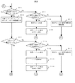
図3及び図4はフレームの受信からの全体的な処理フローを示した図である。まず、フレームを受信した契機でそのフレームがCPUまたはRCUから受信したフレームかを判定する(301)。もしCPUまたはRCUからの受信フレームならば、受信バッファからフレーム情報、コマンド情報、パラメタ情報を取り込む(302)。
【0039】
次に、受信したフレームがCPUから受信したかを判定する(303)。もしCPUからの受信フレームならば、リモートコピー対象CCWチェイン情報が確定か、不確定かを判定する(304)。
【0040】
もし、リモートコピー対象CCWチェイン情報が不確定ならば、リモートコピー対象外CCWチェイン情報が確定か、不確定かを判定する(305)。もし、リモートコピー対象外CCWチェイン情報が不確定ならば、コマンド情報とパラメタ情報を用いてリモートコピー要否の解析処理を行う(306)。この解析処理については図5で詳細を述べる。
【0041】
次に、306の解析結果から、リモートコピー要情報が要に設定されているかを判定する(307)。もしリモートコピー要情報が不確定ならば、リモートコピー不要情報が不要に設定されているかを判定する(308)。もし、リモートコピー不要情報が不確定ならば、受信したフレームを内部バッファに転送し、以降のコマンドフレームの解析処理でリモートコピー要否が決定するまで蓄積しておく(309)。
【0042】
次に当該フレームのMCU内での処理を実行し(310)、フレーム受信処理に戻る。もし、308の判定処理で、リモートコピー不要情報が不要に設定されているならば、リモートコピー処理が不要であることから、今まで内部バッファに蓄積しておいたフレームを解放する(311)。
【0043】
次に、当該CCWチェインがリモートコピー対象外CCWチェインであることを示す情報を設定する(312)。次に、当該フレームのMCU内での処理を実行し(313)、フレーム受信処理に戻る。もし、307の判定処理で、リモートコピー要情報が要に設定されているならば、リモートコピー処理が必要であることから、まずフレーム情報を内部バッファに転送する(321)。
【0044】
次に、今まで内部バッファに蓄積したフレームとともに、ヘッダの変換処理を実行する(322)。このヘッダ変換の対象となるヘッダ情報については、図6で詳細を述べる。次に、ヘッダを変換したフレームを送信バッファに転送し、RCUへ送信する(323)。次に、当該CCWチェインがリモートコピー対象CCWチェインであることを示す情報を設定する(324)。
【0045】
次に、当該フレームのMCU内での処理を実行し(325)、フレーム受信処理に戻る。もし、305の判定処理で、リモートコピー対象外CCWチェイン情報が確定していたならば、リモートコピー処理が不要であることから、311以降の処理へ移る。もし、304の判定処理で、リモートコピー対象CCWチェイン情報が確定していたならば、リモートコピーが必要であることから、321以降の処理へ移る。もし、303の判定処理で、MCUからの受信フレームならば、MCU側での当該受信フレーム相当の処理が終了しているかを判定する(331)。もし、処理終了済みならば、CPUにフレームを送信する必要があることから、まずフレーム情報を内部バッファに転送する(332)。次に、ヘッダの変換処理を実行する(333)。
【0046】
次に、ヘッダを変換したフレームを送信バッファに転送し、CPUへ送信し(334)、フレーム受信処理に戻る。もし、331の判定処理で、MCU側での当該受信フレーム相当の処理が終了していないならば、当該フレームがRCUで処理終了していることを示す情報を設定し(341)、フレーム受信処理に戻る。もし、301の判定処理で、MCU内部でのフレームならば、RCU側での当該受信内部フレーム相当の処理が終了しているかを判定する(351)。
【0047】
もし、処理終了済みならば、送信バッファ上に送信フレームを生成し、CPUに送信し(352)、フレーム受信処理に戻る。もし、351の判定処理で、RCU側での当該受信内部フレーム相当の処理が終了していないならば、当該フレームがMCUで処理終了していることを示す情報を設定し(361)、フレーム受信処理に戻る。
【0048】
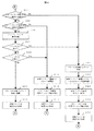
図5は受信したフレーム内のコマンド情報及び、パラメタ情報からリモートコピー要否を解析するフローを示した図である。まず、コマンド情報及び、パラメタ情報を取り込む(401)。次に、コマンドがREAD(読み出し処理)またはWRITE(書き込み処理)の可能性のあるコマンドかを判定する(402)。もし、READまたはWRITEの可能のあるコマンドならば、READまたはWRITE系コントロールコマンドかを判定する(403)。
【0049】
もし、READまたはWRITE系のコントロールコマンドであるならば、パラメタ情報及び、MCUで管理しているリモートコピー対象領域情報より、当該CCWチェインがリモートコピー対象範囲へのWRITEアクセスかを判定する(404)。
【0050】
もし、リモートコピー対象範囲へのWRITEアクセスであることが断定できなかったならば、コマンド情報からコマンドチェイン条件を判定する(405)。もし、コマンドチェインしないならば、リモートコピー対象外のCCWチェインであるため、リモートコピー不要情報を設定し(406)、次の処理へ移る。もし、405の判定処理で、コマンドチェインするのであれば、リモートコピー要否が不確定であるため、リモートコピー情報は不確定のまま、次の処理へ移る。もし、404の判定処理で、リモートコピー対象範囲へのWRITEアクセスであったならば、リモートコピーが必要であることから、リモートコピー要情報を設定し(411)、次の処理へ移る。
【0051】
もし、403の判定処理で、READまたはWRITEコマンドそのものであったならば、WRITEコマンドであるか、READコマンドであるか判定する(421)。もし、READコマンドであるならば、コマンド情報からコマンドチェイン条件を判定する(422)。
【0052】
もし、コマンドチェインしないならば、リモートコピー対象外のCCWチェインであるため、リモートコピー不要情報を設定し(423)、次の処理へ移る。もし、422の判定処理で、コマンドチェインするのであれば、リモートコピー要否が不確定であるため、リモートコピー情報は不確定のまま、次の処理へ移る。もし、421の判定処理で、WRITEコマンドであるならば、MCUで管理しているリモートコピー対象領域情報より、リモートコピー対象範囲へのアクセスかを判定する(431)。
【0053】
もし、リモートコピー対象範囲へのアクセスならば、リモートコピーが必要であるため、リモートコピー要情報を設定して(432)、次の処理へ移る。もし、431の判定処理で、リモートコピー対象範囲へのアクセスでないならば、リモートコピーが不要であるため、リモートコピー不要情報を設定し(441)、次の処理へ移る。
【0054】
もし、402の判定処理で、READまたはWRITEの可能性ないコマンドあるならば、リモートコピーが不要であるため、リモートコピー不要情報を設定し(451)、次の処理へ移る。
【0055】
図6はFICONデバイスレベルのフレームフォーマットとヘッダ変換処理で変換対象となる情報を示した図である。FICONデバイスレベルのフレームは、Start of Frame(SOF) 4バイトと、FC-PH Frame Header 24バイト(501)と、FC-SB-2 Header 8バイト(502)と、IU Header 8バイトと、DIB Header 12バイトと、FC-SB-2 LRC 4バイトと、DIB Data 0から2016バイトと、FC-PH LRC 4バイトと、End of Frame(EOF) 4バイトから構成される。
【0056】
但し、FC−SB−2の階層では、8192バイトのインフォーメションユニット(以降IUと称す)という単位でデータを扱うため、FC-SB-2 HeaderからDIB Dataまでの合計が2048バイトを超えるIUの場合は、Start of Frame(SOF) 4バイトと、FC-PH Frame Header 24バイト(501)と、DIB Data 0から2048バイトと、FC-PH LRC 4バイトと、End of Frame(EOF) 4バイトから構成されるフレームとなる。
【0057】
このうち、501のFC-PH Frame Headerは、R_CTL Field 1バイトと、D_ID Field 3バイト(511)と、CS_CTL Field 1バイトと、S_ID Field 3バイト(512)と、TYPE Field 1バイトと、F_CTL Field 3バイトと、SEQ_ID Field 1バイトと、DF_CTL Field 1バイトと、SEQ_CNT Field 2バイトと、OX_ID Field 2バイト(513)と、RX_ID 2バイトと、Parameter Field 4バイトから構成される。また、502のFC-SB-2 Headerは、Reserved 1バイトと、Channel Image ID 1バイト(521)と、Reserved 1バイトと、Control-Unit Image ID 1バイト(522)と、Device Address 2バイト(523)と、Reserved 2バイトから構成される。
【0058】
CPUから受信したフレームをRCUに送信するためのヘッダ変換処理では、MCU内で管理している、リモートコピーにより作成されたペアボリュームのペア情報をもとに、まずフレームの送信先を示すD_ID(511)をMCUのD_IDからRCUのD_IDに変換する。また、フレームの送信元を示すS_ID(512)をCPUのS_IDからMCUのS_IDに変換する。また、CCWチェインのエクスチェンジを示すOX_ID(513)をCPUで管理しているOX_IDからMCUで管理するOX_IDに変換する。また、CCWチェインの処理対象となる論理パスのCH Image ID(521)をCPU−MCU間の論理パスのCH Image IDからMCU−RCU間の論理パスのCH Image IDに変換する。
【0059】
また、CCWチェインの処理対象となる論理パスのCU Image ID(522)をCPU−MCU間の論理パスのCU Image IDからMCU−RCU間の論理パスのCU Image IDに変換する。また、CCWチェインの処理対象となるDevice Address(523)をMCUのDevice AddressからリモートコピーのペアとなるRCUのDevice Addressに変換する。
【0060】
一方、RCUから受信したフレームをCPUに送信するためのヘッダ変換処理では、MCU内で管理しているリモートコピーのペア情報をもとに、まずフレームの送信先を示すD_ID(511)をMCUのD_IDからCPUのD_IDに変換する。また、フレームの送信元を示すS_ID(512)をRCUのS_IDからMCUのS_IDに変換する。
【0061】
また、CCWチェインのエクスチェンジを示すOX_ID(513)をRCUで管理しているOX_IDからMCUで管理するOX_IDに変換する。また、CCWチェインの処理対象となる論理パスのCH Image ID(521)をMCU−RCU間の論理パスのCH Image IDからCPU−MCU間の論理パスのCH Image IDに変換する。また、CCWチェインの処理対象となる論理パスのCU Image ID(522)をMCU−RCU間の論理パスのCU Image IDからCPU−MCU間の論理パスのCU Image IDに変換する。また、CCWチェインの処理対象となるDevice Address(523)をRCUのDevice AddressからリモートコピーのペアとなるMCUのDevice Addressに変換する。
【0062】
図7は本発明を適用した時のCPUとMCU間の動作シーケンス及び、MCUからRCU側へのデータ転送タイミングと動作シーケンスを示す図である。まず、CPUからDX(Define Extext)のコマンド及び、DXのパラメタを含むCMD+DATAフレーム(DX CMD+DATA)をMCUに対して送信する(601)。MCUはこれを受けてフレームの解析処理を行う。DXコマンドのパラメタからは、当該CCWチェインがリモートコピー対象であるかは不確定のため、RCUへの送信せず、内部バッファに蓄積する。
【0063】
CPUはこれに続き、LOC(LOCate record)のコマンド及び、パラメタを含むCMD+DATAフレーム(LOC CMD+DATA)をMCUに対して送信する(602)。MCUはこれを受けてフレームの解析処理を行う。LOCコマンドのパラメタには、当該CCWチェインがリモートコピー対象であるかを判定可能な情報が含まれている。
【0064】
ここで、もしリモートコピー要と判定されたならば、先に受領して内部バッファに蓄積中のDX CMD+DATAのヘッダ変換処理を行い、RCUに対して送信する(651)。また、これに続きLOC CMD+DATAのヘッダ変換処理を行い、RCUに対して送信する(652)。
【0065】
CPUは602に続き、レコード1のWRUPD(Write Update Data)コマンド及び、レコード1のデータを含むCMD+DATAフレーム(WRUPD#1 CMD+DATA)をMCUに対して送信する(603)。MCUはこれを受けて、既に当該CCWチェインがリモートコピー対象となっているので、WRUPD#1 CMD+DATAをヘッダの変換処理を行い、RCUに対して送信する(653)。
【0066】
CPUは603に続き、レコード2のWRUPDコマンド及び、レコード2のデータを含むCMD+DATAフレーム(WRUPD#2 CMD+DATA)をMCUに対して送信する(604)。MCUはこれを受けて、既に当該CCWチェインがリモートコピー対象となっているので、WRUPD#2 CMD+DATAをヘッダの変換処理を行い、RCUに対して送信する(654)。
【0067】
RCUは651のDX CMD+DATAを受信し、DXコマンドを受領したことを示すコマンドレスポンスフレーム(CMR)をMCUに対して送信する(655)。MCUはこれを受けて、MCU内部でのDXコマンドの受領処理が完了しているならば、CMRのヘッダ変換処理を行い、CPUに対して送信する(605)。
【0068】
RCUは655に続いて、LOC CMD+DATA、WRUPD#1 CMD+DATA、WRUPD#2 CMD+DATAの処理を実行し、WRUPD#2 CMD+DATAの処理が正常に終了した時点で、WRUPD#2 CMD+DATAが正常終了したことを示すステータスフレーム(STS'0C')をMCUに対して送信する(656)。MCUはこれを受けて、MCU内部でのレコード2のWRUPDコマンドの処理が正常完了しているならば、STS'0C'のヘッダ変換処理を行い、CPUに対して送信する(606)。CPUはこれを受けて、正常終了のステータスを受領したことを示すステータス受領フレーム(STS ACPT)をMCUに対して送信する(607)。
【0069】
MCUはこれを受けて、STS ACPTのヘッダ変換処理を行い、RCUに対して送信し(657)、CCWチェインの処理が完結する。以上、述べたようにデータ転送を並行に行うことができ、データ転送タイミングと動作シーケンスを示す従来技術例(図2)と図7を比較すると、明らかに処理性能が向上することが解かる。
【0070】
【発明の効果】
本発明のデータ保証システムは、FICONプロトコルを用いたリモートコピー処理であり、CPUから受領したフレームをMCU内の内部バッファに一旦格納し、フレームのヘッダ部をRCU送信用に変換し送信することにより、CPU−MCU間とMCU−RCU間のデータ転送を並行に行うことができ処理性能が向上する。また、CPUからの受信とRCUへの送信を同一ポートで実現することができる。
【図面の簡単な説明】
【図1】 ファイバープロトコルを用いたリモートコピーシステムの構成を示す図である。
【図2】 ESCONプロトコル上でのCPUとMCU間の動作シーケンス及び、MCUからRCU側へのデータ転送タイミングと動作シーケンスを示す図である。
【図3】 フレームの受信からの全体的な処理フローを示した図である。
【図4】 フレームの受信からの全体的な処理フローを示した図である。
【図5】 受信したフレーム内のコマンド情報及び、パラメタ情報からリモートコピー要否を解析するフローを示した図である。
【図6】 デバイスレベルのフレームフォーマットとヘッダ変換処理で変換対象となる情報を示した図である。
【図7】 本発明を適用した時のCPUとMCU間の動作シーケンス及び、MCUからRCU側へのデータ転送タイミングと動作シーケンスを示す図である。
【符号の説明】
101・・・中央処理装置(CPU)
102・・・マスタ側ディスク制御装置(MCU)
103・・・マスタ側のディスク駆動装置
104・・・リモート側ディスク制御装置(RCU)
105・・・リモート側のディスク駆動装置
106・・・ディレクタ装置
107・・・CPUとディレクタ装置間を接続するファイバーケーブル
108・・・ディレクタ装置とMCU間を接続するファイバーケーブル
109・・・ディレクタ装置とRCUを接続するファイバーケーブル
111・・・受信バッファ
112・・・送信バッファ
113・・・内部バッファ
114・・・CACHE
115・・・ファイバープロトコル制御部
116・・・チャネルアダプタ制御部
117・・・ディスクアダプタ制御部。 [0001]
BACKGROUND OF THE INVENTION
The present invention relates to a configuration of a central processing unit (hereinafter referred to as a CPU) such as a mainframe or an open server, a master disk control unit (hereinafter referred to as MCU), and a remote disk control unit (hereinafter referred to as RCU). The present invention relates to a synchronous remote copy processing system connected using a channel, and more particularly, to a data guarantee system for performing remote copy processing between an MCU and an RCU at a high speed and a single port.
[0002]
[Prior art]
An MCU (master disk control unit) and an RCU (remote disk control unit) are control units of a disk subsystem, and are respectively connected to disk drive units.
[0003]
The MCU controls the I / O operation from the host processor to the master disk drive and the copy operation between the master and the remote disk drive. Further, the MCU provides a function for managing the status and configuration of the remote copy.
[0004]
The RCU performs a write operation instructed by the MCU.
As a conventional technique for performing synchronous remote copying, a peer-to-to-peer in a configuration in which the CPU, MCU and RCU are connected by an ESCON (Enterprise System Connection) protocol (known example Enterprise Systems Architecture / 390 ESCON I / O Interface). There is Peer Remote Copy (known example: IBM Enterprise Storage Server Peer-to-Peer Remote Copy, a function for maintaining consistency by placing duplicates of the same data on a plurality of Enterprise Storage Servers).
[0005]
The information processing system includes a plurality of channel devices and one or a plurality of input / output devices connected to the channels. The channel is designated for an input / output operation to be performed by a channel command word (CCW) including a command code for the input / output device, a count, and a data address. The CCW is first prepared on the main memory of the CPU by a program. The CCW has a command chain flag, and the channel executes the next CCW continuously after executing the CCW whose flag is “1”. This operation is called a command chain.
[0006]
In general, synchronous remote copy processing using the ESCON protocol is a protocol that transmits a status indicating whether the command has been normally completed for each command chain between the CPU and the MCU. A method is employed in which data is transferred to the RCU when the data is determined.
[0007]
For example, when writing two records, a CCW chain of DX (Define Extext) / LOC (LOCate record) / WRUPD (Write Update Data) / WRUPD is used (known example IBM 3990/9390 Storage Control Reference). "DEFINE EXTENT", "LOCATE RECORD" (The number of records processed and the data length are given by the LOCATE RECORD command) These are disk control commands that specify the alignment of the disk head on the device specified by the channel, “Write Update Data” instructs to update data there. FIG. 2 shows an operation sequence between the CPU and the MCU when the CCW chain is issued, and a data transfer timing and an operation sequence from the MCU to the RCU.
[0008]
First, a DX command frame (DX CMD), which is the first command, is transmitted from the CPU to the MCU (201). In response to this, the MCU transmits a command response frame (CMR) indicating that the DX command has been received to the CPU (202).
[0009]
In response to this, the CPU transmits a command response reception frame (ACPT CMR) indicating reception of the command response to the MCU (203). Subsequently, the CPU transmits a DX command data frame (DX DATA) to the MCU (204). In response to this, the MCU executes the processing of the DX command. If the processing ends normally, the MCU transmits a status frame (STS'0C ') indicating the normal end to the CPU (205).
[0010]
In response to this, the CPU transmits a LOC command frame (LOC CMD) for command chaining to the DX command to the MCU (206). In response to this, the MCU transmits a command response (CMR) indicating that the LOC command has been received to the CPU (207).
[0011]
In response to this, the CPU transmits a LOC command data frame (LOC DATA) to the MCU (208). In response to this, the MCU executes processing of the LOC command. If the MCU ends normally, the MCU transmits a status frame (STS'0C ') indicating that the LOC command has ended normally to the CPU (209).
[0012]
In response to this, the CPU transmits a WRUPD command frame (WRUPD # 1 CMD) for
[0013]
In response to this, the CPU transmits a WRUPD data frame (WRUPD # 1 DATA) of
[0014]
Further, the MCU executes processing of the WRUPD command of
[0015]
In response to this, the CPU transmits a WRUPD command frame (WRUPD # 2 CMD) for writing the
[0016]
In response to this, the CPU transmits a WRUPD data frame (WRUPD # 2 DATA) of
[0017]
In response to this, the MCU checks whether the last data of the CCW chain or the last data of the track (all data frames of the
[0018]
The MCU receives the WRUPD data frame of the
[0019]
In response to this, the CPU transmits a status reception frame (STS ACPT) indicating that the final status of the CCW chain has been received to the MCU (218). In response to this, the MCU transmits a device level acknowledge frame indicating that the status reception frame has been received to the CPU (219).
[0020]
On the other hand, the RCU receives the data frame of the
[0021]
In response to this, the RCU transmits a device level acknowledgment frame (DEVACK) indicating that the status reception frame has been received to the MCU (256), and the writing process to the remote side is completed.
[0022]
Further, the MCU determines that the writing process to the remote side has been completed by receiving the normal end status from the RCU, and in order to report the device end status at this time, the MCU sends a reconnection request to the CPU. A request connection frame (REQ CON) is transmitted (220).
[0023]
In response to this, the CPU transmits a connection reception frame indicating that the reconnection request has been received to the MCU (221). Upon receiving this, the MCU recognizes that the reconnection has been accepted, and transmits a status frame (STS '04') indicating the device end to the CPU (222).
[0024]
In response to this, the CPU transmits a status reception frame indicating that the device end status has been received to the MCU (223). In response to this, the MCU transmits a device level acknowledgment frame (DEVACK) indicating that the status reception frame has been received to the CPU (224), and the writing process from the CPU is completed.
[0025]
As described above, in the general remote copy process in the ESCON protocol, the data transfer from the MCU to the RCU is started when the data transfer from the CPU to the MCU to the end of the CCW chain or the end of the track is completed. Therefore, data transfer between the CPU and MCU and between the MCU and RCU is not performed in parallel, which affects performance.
[0026]
Next, the fiber channel technology will be described. The basic part of Fiber Channel is standardized by ANSI FC-PH (Fibre Channel PHysical and Signaling). The upper level protocol using the fiber channel is compliant with FC-PH, so that a plurality of upper level protocols can operate on a common fiber channel. FC-PH defines two-way simultaneous data transfer, which is a feature of Fiber Channel, so that data can be transmitted and received in parallel.
[0027]
In addition, the concept of exchange is defined in FC-PH. A series of transmission / reception sequences of a command frame and a data frame exchanged with the disk control device with respect to one input / output command issued by the CPU to the disk subsystem is called exchange. Multiple processing is possible by using this exchange.
[0028]
FC-PH defines a general fiber channel frame structure. The frame is composed of SOF (Start_of_Frame), Frame Header, DataField, CRC (Cyclic Redundancy Check character), and EOF (End_of_Frame). Of these, D_ID (Destination_ID) indicating the destination address in the Frame Header and the source address S_ID (Source_ID) indicated is included. The transmission direction is determined by the common D_ID and S_ID defined by the FC-PH.
[0029]
[Problems to be solved by the invention]
An object of the present invention is to perform data transfer between a CPU and an MCU and between an MCU and an RCU in parallel in remote copy processing, and realize reception from the CPU and transmission to the RCU on the same port.
[0030]
[Means for Solving the Problems]
The data assurance system according to the present invention is a remote copy process using a fiber channel protocol, and is composed of a header conversion buffer and a header conversion control unit, utilizing the bidirectional data transfer and multiplexing processes characteristic of the fiber channel protocol. Using the header conversion circuit, the frame received from the CPU is temporarily stored in the header conversion buffer in the MCU, and the header portion of the frame is converted for RCU transmission and transmitted.
[0031]
DETAILED DESCRIPTION OF THE INVENTION
Hereinafter, a data guarantee system in a fiber channel according to an embodiment of the present invention will be described with reference to the drawings.
[0032]
FIG. 1 is a diagram showing a configuration of a remote copy system using a fiber channel protocol according to an embodiment of the present invention. The configuration of the present embodiment mainly includes a CPU (101) that is a central processing unit, an MCU (102) that is a master-side disk control device, a DKU (103) that is a master-side disk drive device, and a remote-side disk. An RCU (104) that is a control device, a DKU (105) that is a disk drive device on the remote side, a director device (106) that switches the connection between the CPU, the MCU, and the RCU, and a connection between the CPU and the director device. A fiber cable (107), a fiber cable (108) for connecting the director device and the MCU, and a fiber cable (109) for connecting the director device and the RCU are included.
[0033]
The central processing unit may be a mainframe or an open server. Further, the connection configuration may be a configuration in which the CPU-MCU and the MCU-RCU are directly coupled by a fiber cable without interposing the director device.
[0034]
Further, there may be a configuration in which a plurality of RCUs exist, and the MCU-director is connected to the plurality of RCUs from the director device with a single fiber cable, or the MCU is directly connected to the plurality of RCUs.
[0035]
Furthermore, there may be a configuration in which a plurality of CPUs exist, and the MCU-director is connected to the plurality of CPUs from the director device with a single fiber cable, or directly connected to the MCU and the plurality of CPUs. The internal structure of the MCU that forms the basis of the present invention includes a reception buffer (111) for receiving frames from the CPU or RCU, a transmission buffer (112) for transmitting frames to the CPU or RCU, and reception from the CPU. Header conversion buffer (113) for header conversion of the received frame and transfer to the RCU, or header conversion buffer (113) for header conversion of the frame received from the RCU and transfer to the CPU, and a frame received from the CPU. An internal buffer (114) that is a temporary data storage area for transfer to the CACHE (115) in the MCU, a CACHE (115) that stores a part of drive information for the purpose of high-speed processing, etc., and an RCU transmission Therefore, a fiber protocol control unit (116) for controlling header conversion processing and the like, and an internal buffer 114) and CACHE (115) channel adapter control unit for controlling data processing between the (117), and a disk adapter control unit (118) for controlling CACHE and (115) the data processing between disk drives.
[0036]
For example, FICON (Fibre Channel Connection), which is a fiber channel of the mainframe that connects the CPU, MCU, and RCU, is FC-SB-2 (FIBER CHANNEL SINGLE-BYTE COMMAND CODE SET-2 MAPPING PROTOCOL standardized by ANSI). ). As a feature of this FICON, since a fiber channel protocol is used, transmission and reception can be performed in both directions, and a unit of exchange can be processed in a multiplexed manner.
[0037]
That is, while receiving CCW chain data for write processing from the CPU to the MCU on a single cable, CCW chain data for write processing from the MCU to the RCU can be transmitted. In addition, FICON has a feature of transmitting a command chain in a pipeline, so that commands can be issued continuously in a pipeline without receiving a normal end status for each command in the CCW chain. . Using this configuration, the frame issued by the CPU is stored in the reception buffer, the frame is analyzed by the FICON protocol control unit, and as a result, if the frame needs to be transferred to the remote RCU, it is stored in the internal buffer. It is possible to perform parallel processing to the RCU by transferring and performing header conversion processing and transferring it to the transmission buffer.
[0038]
3 and 4 are diagrams showing an overall processing flow from reception of a frame. First, it is determined whether the frame is received from the CPU or RCU when the frame is received (301). If the received frame is from the CPU or RCU, frame information, command information, and parameter information are fetched from the reception buffer (302).
[0039]
Next, it is determined whether the received frame is received from the CPU (303). If the received frame is from the CPU, it is determined whether the remote copy target CCW chain information is confirmed or not (304).
[0040]
If the remote copy target CCW chain information is indefinite, it is determined whether the remote copy target CCW chain information is final or indeterminate (305). If the remote copy non-target CCW chain information is indeterminate, the remote copy necessity analysis process is performed using the command information and parameter information (306). Details of this analysis processing will be described with reference to FIG.
[0041]
Next, it is determined from the analysis result of 306 whether or not the remote copy required information is set as required (307). If the remote copy required information is uncertain, it is determined whether the remote copy unnecessary information is set to be unnecessary (308). If the remote copy unnecessary information is uncertain, the received frame is transferred to the internal buffer and stored until it is determined whether the remote copy is necessary or not in the subsequent command frame analysis processing (309).
[0042]
Next, the process of the frame in the MCU is executed (310), and the process returns to the frame reception process. If the remote copy unnecessary information is set to be unnecessary in the determination processing of 308, since the remote copy processing is unnecessary, the frames stored in the internal buffer until then are released (311).
[0043]
Next, information indicating that the CCW chain is not a remote copy target CCW chain is set (312). Next, the process of the frame in the MCU is executed (313), and the process returns to the frame reception process. If the remote copy required information is set as required in the determination processing of 307, the remote copy processing is required, so the frame information is first transferred to the internal buffer (321).
[0044]
Next, the header conversion process is executed together with the frames accumulated in the internal buffer so far (322). Details of the header information to be subjected to header conversion will be described with reference to FIG. Next, the frame with the converted header is transferred to the transmission buffer and transmitted to the RCU (323). Next, information indicating that the CCW chain is a remote copy target CCW chain is set (324).
[0045]
Next, the process of the frame in the MCU is executed (325), and the process returns to the frame reception process. If the CCW chain information not subject to remote copy is determined in the determination process of 305, the remote copy process is unnecessary, and the process proceeds to 311 and subsequent steps. If the remote copy target CCW chain information has been determined in the
[0046]
Next, the frame whose header has been converted is transferred to the transmission buffer, transmitted to the CPU (334), and the process returns to the frame reception process. If the process corresponding to the received frame on the MCU side is not completed in the determination process of 331, information indicating that the frame has been processed by the RCU is set (341), and the frame receiving process is performed. Return to. If it is determined in 301 that the frame is inside the MCU, it is determined whether the processing corresponding to the received internal frame on the RCU side has been completed (351).
[0047]
If the process has been completed, a transmission frame is generated on the transmission buffer, transmitted to the CPU (352), and the process returns to the frame reception process. If the processing corresponding to the received internal frame on the RCU side is not completed in the determination processing of 351, information indicating that the frame has been processed by the MCU is set (361), and the frame is received. Return to processing.
[0048]
FIG. 5 shows a flow for analyzing the necessity of remote copy from the command information and parameter information in the received frame. First, command information and parameter information are fetched (401). Next, it is determined whether the command has a possibility of READ (read processing) or WRITE (write processing) (402). If the command is capable of READ or WRITE, it is determined whether it is a READ or WRITE control command (403).
[0049]
If it is a READ or WRITE control command, it is determined from the parameter information and the remote copy target area information managed by the MCU whether the CCW chain is a WRITE access to the remote copy target range (404). .
[0050]
If the WRITE access to the remote copy target range cannot be determined, the command chain condition is determined from the command information (405). If the command chain does not exist, the CCW chain is not subject to remote copy, so remote copy unnecessary information is set (406), and the process proceeds to the next process. If the command chain is determined in the
[0051]
If it is a READ or WRITE command itself in the determination processing of 403, it is determined whether it is a WRITE command or a READ command (421). If it is a READ command, the command chain condition is judged from the command information (422).
[0052]
If the command chain does not exist, the CCW chain is not subject to remote copy, so remote copy unnecessary information is set (423), and the process proceeds to the next process. If the command chain is determined in the determination process of 422, it is uncertain whether or not the remote copy is necessary, so the remote copy information remains uncertain and the process proceeds to the next process. If it is a WRITE command in the determination process of 421, it is determined from the remote copy target area information managed by the MCU whether the access is to the remote copy target range (431).
[0053]
If the access is to the remote copy target range, remote copy is necessary, so the remote copy required information is set (432), and the process proceeds to the next process. If it is determined in the determination process 431 that the remote copy target range is not accessed, remote copy is unnecessary, so remote copy unnecessary information is set (441), and the process proceeds to the next process.
[0054]
If it is determined in
[0055]
FIG. 6 is a diagram showing information to be converted by the FICON device level frame format and header conversion processing. The FICON device level frame consists of 4 bytes of Start of Frame (SOF), FC-PH Frame Header 24 bytes (501), FC-SB-2
[0056]
However, in the FC-SB-2 layer, since data is handled in units of 8192-byte information units (hereinafter referred to as IU), the IU in which the total from FC-SB-2 Header to DIB Data exceeds 2048 bytes In this case, Start of Frame (SOF) 4 bytes, FC-PH Frame Header 24 bytes (501), DIB Data 0 to 2048 bytes, FC-
[0057]
Of these, FC-
[0058]
In the header conversion process for transmitting the frame received from the CPU to the RCU, first, based on the pair information of the pair volume created by the remote copy managed in the MCU, the D_ID ( 511) is converted from the D_ID of the MCU to the D_ID of the RCU. Also, S_ID (512) indicating the transmission source of the frame is converted from the S_ID of the CPU to the S_ID of the MCU. Also, OX_ID (513) indicating the exchange of the CCW chain is converted from OX_ID managed by the CPU to OX_ID managed by the MCU. Also, the CH Image ID (521) of the logical path to be processed in the CCW chain is converted from the CH Image ID of the logical path between the CPU and MCU to the CH Image ID of the logical path between MCU and RCU.
[0059]
Also, the CU Image ID (522) of the logical path to be processed in the CCW chain is converted from the CU Image ID of the logical path between the CPU and MCU to the CU Image ID of the logical path between MCU and RCU. Also, the Device Address (523) to be processed in the CCW chain is converted from the Device Address of the MCU to the Device Address of the RCU that is the remote copy pair.
[0060]
On the other hand, in the header conversion process for transmitting the frame received from the RCU to the CPU, based on the remote copy pair information managed in the MCU, first, the D_ID (511) indicating the transmission destination of the frame is set in the MCU. D_ID is converted to CPU D_ID. Also, S_ID (512) indicating the transmission source of the frame is converted from the S_ID of the RCU to the S_ID of the MCU.
[0061]
Also, OX_ID (513) indicating the exchange of the CCW chain is converted from OX_ID managed by the RCU to OX_ID managed by the MCU. Also, the CH Image ID (521) of the logical path to be processed in the CCW chain is converted from the CH Image ID of the logical path between MCU and RCU to the CH Image ID of the logical path between CPU and MCU. Also, the CU Image ID (522) of the logical path to be processed in the CCW chain is converted from the CU Image ID of the logical path between the MCU and RCU to the CU Image ID of the logical path between the CPU and MCU. Also, the Device Address (523) to be processed in the CCW chain is converted from the Device Address of the RCU to the Device Address of the MCU that is the remote copy pair.
[0062]
FIG. 7 is a diagram showing an operation sequence between the CPU and the MCU and a data transfer timing and an operation sequence from the MCU to the RCU when the present invention is applied. First, the CPU transmits a DX (Define Extext) command and a CMD + DATA frame (DX CMD + DATA) including DX parameters to the MCU (601). In response to this, the MCU performs frame analysis processing. From the parameters of the DX command, it is uncertain whether the CCW chain is a remote copy target, so it is not transmitted to the RCU but stored in the internal buffer.
[0063]
Subsequently, the CPU transmits a CMD + DATA frame (LOC CMD + DATA) including a LOC (LOCate record) command and parameters to the MCU (602). In response to this, the MCU performs frame analysis processing. The parameter of the LOC command includes information that can determine whether the CCW chain is a remote copy target.
[0064]
If it is determined that remote copy is necessary, the header conversion process of DX CMD + DATA received first and stored in the internal buffer is performed and transmitted to the RCU (651). Following this, the header conversion processing of LOC CMD + DATA is performed and transmitted to the RCU (652).
[0065]
Following 602, the CPU transmits a WRUPD (Write Update Data) command of
[0066]
Following 603, the CPU transmits a WRUPD command of
[0067]
The RCU receives DX CMD + DATA of 651 and transmits a command response frame (CMR) indicating that the DX command has been received to the MCU (655). In response to this, the MCU performs a CMR header conversion process and transmits it to the CPU if the DX command reception process in the MCU is completed (605).
[0068]
The RCU executes the processing of LOC CMD + DATA,
[0069]
In response, the MCU performs header conversion processing of the STS ACPT and transmits it to the RCU (657), and the processing of the CCW chain is completed. As described above, data transfer can be performed in parallel, and it can be seen that the processing performance is clearly improved by comparing FIG. 7 with the prior art example (FIG. 2) showing the data transfer timing and operation sequence.
[0070]
【The invention's effect】
The data guarantee system according to the present invention is a remote copy process using the FICON protocol. The frame received from the CPU is temporarily stored in an internal buffer in the MCU, and the header part of the frame is converted for RCU transmission and transmitted. Data transfer between the CPU and MCU and between the MCU and RCU can be performed in parallel, and the processing performance is improved. Also, reception from the CPU and transmission to the RCU can be realized on the same port.
[Brief description of the drawings]
FIG. 1 is a diagram showing a configuration of a remote copy system using a fiber protocol.Is.
FIG. 2 is a diagram showing an operation sequence between the CPU and the MCU on the ESCON protocol, and a data transfer timing and an operation sequence from the MCU to the RCU side.Is.
FIG. 3 is a diagram showing an overall processing flow from reception of a frame.Is.
FIG. 4 is a diagram showing an overall processing flow from reception of a frame.Is.
FIG. 5 is a diagram showing a flow for analyzing whether or not a remote copy is necessary from command information and parameter information in a received frame;Is.
FIG. 6 is a diagram showing information to be converted by a device level frame format and header conversion processing;Is.
FIG. 7 is a diagram showing an operation sequence between the CPU and the MCU and a data transfer timing and an operation sequence from the MCU to the RCU when the present invention is applied.Is.
[Explanation of symbols]
101 ... Central processing unit(CPU)
102... Master side disk controller(MCU)
103: Master side disk drive device
104... Remote-side disk control device(RCU)
105... Remote side disk drive device
106 ... Director device
107 ... Fiber cable connecting the CPU and the director device
108 ... Fiber cable connecting the director unit and MCU
109 ... Fiber cable connecting the director unit and the RCU
111... Reception buffer
112... Transmission buffer
113 ... Internal buffer
114 ... CACHE
115: Fiber protocol control unit
116: Channel adapter controller
117... Disk adapter controller.
Claims (2)
前記マスタ側ディスク装置は、前記ケーブルを接続する第1のポートと、前記第1のポートに接続するヘッダ変換バッファと、前記ヘッダ変換バッファのフレームのヘッダ部の情報を変換するヘッダ変換制御回路と、前記中央処理装置からのデータが読み書きされるディスクドライブと、を有し、
前記中央処理装置からマスタ側ディスク装置へのデータ書き込みのチャネルコマンドワードチェイン処理と前記マスタ側ディスク装置からリモート側ディスク装置へのデータ書き込みのチャネルコマンドワードチェイン処理とを並行して、前記中央処理装置からの受信と前記リモート側ディスク装置への送信とを同一の前記第1のポートで行うものであり、
前記中央処理装置からマスタ側ディスク装置に発行されたデータ書き込み処理のチャネルコマンドワードチェインのフレームを、前記マスタ側ディスク装置の前記第1のポートで受信し、当該フレームのデータ書き込み処理を前記マスタ側ディスク装置内で行い、当該マスタ側ディスク装置内の処理と並行して、前記チャネルコマンドワードチェインのフレームを前記ヘッダ変換バッファに格納して前記ヘッダ変換制御回路によって当該フレームのヘッダ部の情報を前記リモート側ディスク装置への送信用にヘッダ変換し、当該変換されたフレームを前記第1のポートを介して前記リモート側ディスク装置へ送信し、
前記ヘッダ変換では、ヘッダ内の送信先ID及び送信元IDを変え、チャネルコマンドワードチェインの対象のデバイスアドレスをマスタ側のデバイスアドレスからリモート側のデバイスアドレスに変え、
前記リモート側ディスク装置内では、前記マスタ側ディスク装置から受信した前記書き込み処理のチャネルコマンドワードチェインのフレームを処理してその応答を前記マスタ側ディスク装置へ送信し、
前記マスタ側ディスク装置では、前記マスタ側ディスク装置内の処理が終了し且つ前記リモート側ディスク装置からの応答を受けると前記中央処理装置へ応答を送信すること、を特徴とするデータ保証システム。 The central processing unit and the master side disk unit are connected by a cable, the master side disk unit and the remote side disk unit are connected by a cable, and the central processing unit, the master side disk unit and the remote side disk unit are bidirectional. Connected via an interface that performs multiple data transfers and multiple processing.
The master disk device includes: a first port for connecting the cable; a header conversion buffer connected to the first port; a header conversion control circuit for converting information of a header portion of a frame of the header conversion buffer; A disk drive for reading and writing data from the central processing unit,
The central processing unit concurrently performs channel command word chain processing for writing data from the central processing unit to the master side disk device and channel command word chain processing for writing data from the master side disk unit to the remote side disk unit. And reception to the remote disk device at the same first port,
A channel command word chain frame for data write processing issued from the central processing unit to the master side disk unit is received by the first port of the master side disk unit, and data write processing of the frame is performed on the master side In parallel with the processing in the master-side disk device, the frame of the channel command word chain is stored in the header conversion buffer, and the header conversion control circuit stores the information of the header portion of the frame in the disk device. Converting the header for transmission to the remote disk device, and transmitting the converted frame to the remote disk device via the first port;
In the header conversion, the transmission destination ID and transmission source ID in the header are changed, the device address of the channel command word chain is changed from the device address on the master side to the device address on the remote side,
In the remote disk device, the frame command word chain frame of the write process received from the master disk device is processed and the response is transmitted to the master disk device,
The master side disk device transmits a response to the central processing unit upon completion of processing in the master side disk device and receiving a response from the remote side disk device .
前記マスタ側ディスク装置は、前記ファイバーケーブルを接続する第1のポートと、前記第1のポートに接続する送受信バッファと、前記送受信バッファに接続するヘッダ変換バッファを含む内部バッファと、フレームのヘッダ部を変換するヘッダ変換を含む前記ファイバーチャネルプロトコルに従う制御を行うプロトコル制御部と、前記内部バッファに接続するキャッシュメモリと、前記キャッシュメモリに接続するディスクドライブと、前記内部バッファ−キャッシュメモリ間のデータ処理を制御するチャネルアダプタ制御部と、前記キャッシュメモリ−ディスクドライブ間のデータ処理を制御するディスクアダプタ制御部と、を有し、
前記ファイバーチャネルプロトコルに従って前記中央処理装置からマスタ側ディスク装置へのデータ書き込みのチャネルコマンドワードチェイン処理と前記マスタ側ディスク装 置からリモート側ディスク装置へのデータ書き込みのチャネルコマンドワードチェイン処理とを並行して、前記中央処理装置からの受信と前記リモート側ディスク装置への送信とを同一の前記第1のポートで行うものであり、
前記中央処理装置からマスタ側ディスク装置に発行されたデータ書き込み処理のチャネルコマンドワードチェインのフレームを、前記マスタ側ディスク装置は、前記第1のポートで受信して前記送受信バッファに格納し、当該フレームを前記プロトコル制御部によって解析し前記リモート側ディスク装置へ転送する場合には当該フレームを前記ヘッダ変換バッファに格納し、
前記マスタ側ディスク装置内の処理として、前記内部バッファの前記書き込み処理のフレームのデータを前記チャネルアダプタ制御部によって前記キャッシュメモリへ格納し、前記キャッシュメモリのデータを前記ディスクアダプタ制御部によって前記ディスクドライブへ書き込み処理を行い、
前記マスタ側ディスク装置内の処理と並行して、前記ヘッダ変換バッファのフレームを前記プロトコル制御部によって前記リモート側ディスク装置への送信用にヘッダ変換し、当該変換されたフレームを前記送受信バッファへ転送し当該送受信バッファから前記第1のポートを介して前記リモート側ディスク装置へ送信し、
前記ヘッダ変換では、ヘッダ内の送信先IDをマスタ側からリモート側へ変え、送信元IDを中央処理装置側からマスタ側へ変え、チャネルコマンドワードチェインの対象のデバイスアドレスをマスタ側のデバイスアドレスからリモート側のデバイスアドレスに変え、チャネルコマンドワードチェインのエクスチェンジのIDをマスタ側が管理するIDに変え、チャネルコマンドワードチェインのパスのIDをマスタ−リモート間のパスのIDに変え、
前記リモート側ディスク装置内では、前記マスタ側ディスク装置から受信した前記書き込み処理のチャネルコマンドワードチェインのフレームを処理してその応答を前記マスタ側ディスク装置へ送信し、
前記マスタ側ディスク装置では、前記マスタ側ディスク装置内の処理が終了し且つ前記リモート側ディスク装置からの応答を受けると前記ヘッダ変換して前記中央処理装置へ応答を送信すること、を特徴とするデータ保証システム。 One or a plurality of central processing units and a master side disk unit are connected by a fiber cable, and the master side disk unit and one or a plurality of remote side disk units are connected by a fiber cable, and the central processing unit-master side disk There is a director device for switching the connection between the devices and between the master disk device and the remote disk device, and the director device and the master disk device are physically connected by the same fiber cable. The central processing unit, the master-side disk unit, and the remote-side disk unit are connected using a fiber channel protocol that performs bidirectional data transfer and multiprocessing,
The master disk device includes a first port for connecting the fiber cable, a transmission / reception buffer connected to the first port, an internal buffer including a header conversion buffer connected to the transmission / reception buffer, and a header portion of a frame. A protocol control unit that performs control according to the fiber channel protocol including header conversion for converting data, a cache memory connected to the internal buffer, a disk drive connected to the cache memory, and data processing between the internal buffer and the cache memory A channel adapter controller that controls the disk adapter, and a disk adapter controller that controls data processing between the cache memory and the disk drive,
Parallel channel command word chain process of writing data to the central processing channel command word chain processing and the master disk instrumentation placed remotely from side disk apparatus writing data from the device to the master disk device according to the Fiber Channel Protocol Receiving from the central processing unit and transmitting to the remote-side disk device at the same first port,
A channel command word chain frame for data write processing issued from the central processing unit to the master side disk unit is received by the master side disk unit at the first port and stored in the transmission / reception buffer. Is analyzed by the protocol control unit and transferred to the remote disk device, the frame is stored in the header conversion buffer,
As processing in the master-side disk device, the frame data of the write processing in the internal buffer is stored in the cache memory by the channel adapter control unit, and the data in the cache memory is stored in the disk drive by the disk adapter control unit. Write to
In parallel with the processing in the master side disk unit, the header conversion buffer frame is converted into a header for transmission to the remote side disk unit by the protocol control unit, and the converted frame is transferred to the transmission / reception buffer. And transmitting from the transmission / reception buffer to the remote disk device via the first port,
In the header conversion, the transmission destination ID in the header is changed from the master side to the remote side, the transmission source ID is changed from the central processing unit side to the master side, and the target device address of the channel command word chain is changed from the device address on the master side. Change the device address on the remote side, change the exchange ID of the channel command word chain to an ID managed by the master side, change the ID of the path of the channel command word chain to the ID of the path between the master and remote,
In the remote disk device, the frame command word chain frame of the write process received from the master disk device is processed and the response is transmitted to the master disk device,
The master-side disk device, when processing in the master-side disk device is completed and receiving a response from the remote-side disk device, converts the header and transmits a response to the central processing unit. Data assurance system.
Priority Applications (1)
| Application Number | Priority Date | Filing Date | Title |
|---|---|---|---|
| JP2001274424A JP4148663B2 (en) | 2001-09-11 | 2001-09-11 | Data assurance system |
Applications Claiming Priority (1)
| Application Number | Priority Date | Filing Date | Title |
|---|---|---|---|
| JP2001274424A JP4148663B2 (en) | 2001-09-11 | 2001-09-11 | Data assurance system |
Publications (3)
| Publication Number | Publication Date |
|---|---|
| JP2003085017A JP2003085017A (en) | 2003-03-20 |
| JP2003085017A5 JP2003085017A5 (en) | 2005-06-09 |
| JP4148663B2 true JP4148663B2 (en) | 2008-09-10 |
Family
ID=19099453
Family Applications (1)
| Application Number | Title | Priority Date | Filing Date |
|---|---|---|---|
| JP2001274424A Expired - Fee Related JP4148663B2 (en) | 2001-09-11 | 2001-09-11 | Data assurance system |
Country Status (1)
| Country | Link |
|---|---|
| JP (1) | JP4148663B2 (en) |
Families Citing this family (7)
| Publication number | Priority date | Publication date | Assignee | Title |
|---|---|---|---|---|
| US7412718B2 (en) | 2003-11-20 | 2008-08-12 | International Business Machines Corporation | Method for bidirectional data transfer |
| JP4434857B2 (en) | 2003-12-04 | 2010-03-17 | 株式会社日立製作所 | Remote copy system and system |
| JP4887618B2 (en) | 2004-11-19 | 2012-02-29 | 日本電気株式会社 | Storage system, replication method and program thereof |
| JP4963808B2 (en) * | 2005-08-05 | 2012-06-27 | 株式会社日立製作所 | Storage control system |
| WO2016117078A1 (en) * | 2015-01-22 | 2016-07-28 | 株式会社日立製作所 | Storage system |
| JP6683160B2 (en) | 2017-03-27 | 2020-04-15 | 日本電気株式会社 | Storage system and communication method |
| JP2019153864A (en) * | 2018-03-01 | 2019-09-12 | Necプラットフォームズ株式会社 | Communication device and communication system |
-
2001
- 2001-09-11 JP JP2001274424A patent/JP4148663B2/en not_active Expired - Fee Related
Also Published As
| Publication number | Publication date |
|---|---|
| JP2003085017A (en) | 2003-03-20 |
Similar Documents
| Publication | Publication Date | Title |
|---|---|---|
| US6862648B2 (en) | Interface emulation for storage devices | |
| US7711871B1 (en) | Interface device and method for command processing | |
| US6449631B1 (en) | Method and apparatus for transmitting data in a network wherein acknowledgment signals are transmitted to acknowledge receipt of data | |
| JP5047365B2 (en) | Virtual formatting method based on allocation unit and device using the method | |
| JP4252301B2 (en) | Storage system and data backup method thereof | |
| JP4406431B2 (en) | System and method for formatting a virtual disk | |
| US7093043B2 (en) | Data array having redundancy messaging between array controllers over the host bus | |
| US7346754B2 (en) | Control method for storage device controller system, and storage device controller system | |
| US5867648A (en) | High speed heterogeneous coupling of computer systems using channel-to-channel protocol | |
| US20060047899A1 (en) | Storage device control apparatus | |
| US6842833B1 (en) | Computer system and method for transferring data between multiple peer-level storage units | |
| KR20010032196A (en) | Method and dedicated frame buffers for receiving frames | |
| JP2005527007A (en) | Block data storage in computer networks | |
| US6105076A (en) | Method, system, and program for performing data transfer operations on user data | |
| JP2001024733A (en) | Data transmission equipment | |
| JP4148663B2 (en) | Data assurance system | |
| US7568062B2 (en) | Data cut-through in an infiniband/fibre channel bridge | |
| JP2723022B2 (en) | Disk device interface and control method thereof | |
| US7490150B2 (en) | Storage system, adapter apparatus, information processing apparatus and method for controlling the information processing apparatus | |
| JP2003085017A5 (en) | ||
| US9201599B2 (en) | System and method for transmitting data in storage controllers | |
| EP0936561A2 (en) | Data transfer method and apparatus on an SCSI bus | |
| US10019405B2 (en) | Apparatus and method for transmitting serial ATA information | |
| JP2004513418A (en) | Standard device interface | |
| US20060015659A1 (en) | System and method for transferring data using storage controllers |
Legal Events
| Date | Code | Title | Description |
|---|---|---|---|
| A521 | Written amendment |
Free format text: JAPANESE INTERMEDIATE CODE: A523 Effective date: 20040826 |
|
| A621 | Written request for application examination |
Free format text: JAPANESE INTERMEDIATE CODE: A621 Effective date: 20040826 |
|
| RD02 | Notification of acceptance of power of attorney |
Free format text: JAPANESE INTERMEDIATE CODE: A7422 Effective date: 20040826 |
|
| RD04 | Notification of resignation of power of attorney |
Free format text: JAPANESE INTERMEDIATE CODE: A7424 Effective date: 20061023 |
|
| A977 | Report on retrieval |
Free format text: JAPANESE INTERMEDIATE CODE: A971007 Effective date: 20080201 |
|
| A131 | Notification of reasons for refusal |
Free format text: JAPANESE INTERMEDIATE CODE: A131 Effective date: 20080212 |
|
| A521 | Written amendment |
Free format text: JAPANESE INTERMEDIATE CODE: A523 Effective date: 20080407 |
|
| TRDD | Decision of grant or rejection written | ||
| A01 | Written decision to grant a patent or to grant a registration (utility model) |
Free format text: JAPANESE INTERMEDIATE CODE: A01 Effective date: 20080603 |
|
| A01 | Written decision to grant a patent or to grant a registration (utility model) |
Free format text: JAPANESE INTERMEDIATE CODE: A01 |
|
| A61 | First payment of annual fees (during grant procedure) |
Free format text: JAPANESE INTERMEDIATE CODE: A61 Effective date: 20080624 |
|
| FPAY | Renewal fee payment (event date is renewal date of database) |
Free format text: PAYMENT UNTIL: 20110704 Year of fee payment: 3 |
|
| R150 | Certificate of patent or registration of utility model |
Free format text: JAPANESE INTERMEDIATE CODE: R150 |
|
| FPAY | Renewal fee payment (event date is renewal date of database) |
Free format text: PAYMENT UNTIL: 20110704 Year of fee payment: 3 |
|
| FPAY | Renewal fee payment (event date is renewal date of database) |
Free format text: PAYMENT UNTIL: 20120704 Year of fee payment: 4 |
|
| FPAY | Renewal fee payment (event date is renewal date of database) |
Free format text: PAYMENT UNTIL: 20130704 Year of fee payment: 5 |
|
| LAPS | Cancellation because of no payment of annual fees |