JP4136825B2 - Image processing apparatus, image processing method, computer-readable storage medium storing program, and program - Google Patents
Image processing apparatus, image processing method, computer-readable storage medium storing program, and program Download PDFInfo
- Publication number
- JP4136825B2 JP4136825B2 JP2003206829A JP2003206829A JP4136825B2 JP 4136825 B2 JP4136825 B2 JP 4136825B2 JP 2003206829 A JP2003206829 A JP 2003206829A JP 2003206829 A JP2003206829 A JP 2003206829A JP 4136825 B2 JP4136825 B2 JP 4136825B2
- Authority
- JP
- Japan
- Prior art keywords
- image
- processing
- image data
- decoding
- image correction
- Prior art date
- Legal status (The legal status is an assumption and is not a legal conclusion. Google has not performed a legal analysis and makes no representation as to the accuracy of the status listed.)
- Expired - Fee Related
Links
- 238000012545 processing Methods 0.000 title claims description 168
- 238000003860 storage Methods 0.000 title claims description 37
- 238000003672 processing method Methods 0.000 title claims description 10
- 238000000034 method Methods 0.000 claims description 100
- 230000008569 process Effects 0.000 claims description 75
- 238000003702 image correction Methods 0.000 claims description 64
- 239000011159 matrix material Substances 0.000 claims description 8
- 238000004364 calculation method Methods 0.000 claims description 5
- 238000001914 filtration Methods 0.000 claims description 5
- 238000013500 data storage Methods 0.000 claims description 2
- 238000006243 chemical reaction Methods 0.000 description 37
- 238000010586 diagram Methods 0.000 description 34
- 230000006870 function Effects 0.000 description 23
- 238000007639 printing Methods 0.000 description 16
- 238000012937 correction Methods 0.000 description 12
- 239000000976 ink Substances 0.000 description 12
- 238000013139 quantization Methods 0.000 description 10
- 239000003086 colorant Substances 0.000 description 6
- 238000009792 diffusion process Methods 0.000 description 4
- 230000000694 effects Effects 0.000 description 4
- 238000012423 maintenance Methods 0.000 description 4
- 238000009826 distribution Methods 0.000 description 3
- 239000004973 liquid crystal related substance Substances 0.000 description 3
- 238000004422 calculation algorithm Methods 0.000 description 2
- 238000010422 painting Methods 0.000 description 2
- 230000004044 response Effects 0.000 description 2
- 241000238370 Sepia Species 0.000 description 1
- 230000005540 biological transmission Effects 0.000 description 1
- 238000004140 cleaning Methods 0.000 description 1
- 238000004891 communication Methods 0.000 description 1
- 230000006835 compression Effects 0.000 description 1
- 238000007906 compression Methods 0.000 description 1
- 238000004590 computer program Methods 0.000 description 1
- 238000005516 engineering process Methods 0.000 description 1
- 238000009434 installation Methods 0.000 description 1
- 238000004519 manufacturing process Methods 0.000 description 1
- 238000012986 modification Methods 0.000 description 1
- 230000004048 modification Effects 0.000 description 1
- 230000003287 optical effect Effects 0.000 description 1
- 229920001690 polydopamine Polymers 0.000 description 1
- 230000009467 reduction Effects 0.000 description 1
- 239000004065 semiconductor Substances 0.000 description 1
- 230000035945 sensitivity Effects 0.000 description 1
- 229910052709 silver Inorganic materials 0.000 description 1
- 239000004332 silver Substances 0.000 description 1
- -1 silver halide Chemical class 0.000 description 1
- 238000012546 transfer Methods 0.000 description 1
Images


Classifications
-
- H—ELECTRICITY
- H04—ELECTRIC COMMUNICATION TECHNIQUE
- H04N—PICTORIAL COMMUNICATION, e.g. TELEVISION
- H04N1/00—Scanning, transmission or reproduction of documents or the like, e.g. facsimile transmission; Details thereof
- H04N1/46—Colour picture communication systems
Description
【0001】
【発明の属する技術分野】
本発明は、画像データに対して所定の画像処理を行う画像処理装置および画像処理方法およびコンピュータが読み取り可能なプログラムを格納した記憶媒体およびプログラムに関するものである。
【0002】
【従来の技術】
近年のデジタル化の波により、従来の銀塩カメラに代わり、デジタルカメラが急激に普及した。これは、パーソナルコンピュータ(以下、PC)が多くの人に浸透したことにより、デジタル化された画像データをより気軽に取り扱うことが出来るようになったことが要因と考えられる。
【0003】
これに、半導体製造技術の高度化により、デジタルカメラで撮影される画像の高画素、高画質化も後押しした。
【0004】
さらに、昨今では携帯電話やPDAと言ったモバイル機器の高機能化に伴い、デジタルカメラを付けられたものが現れ、PCを保有しない人でもデジタル化された写真に接する機会が増えた。
【0005】
これらのユーザのために、PCを介することなく、プリントできるよう、PCに接続しないでも印字可能なプリンタが登場した。これは、ホスト側であるPCで行っていた画像処理の機能を、プリンタ本体にもたせることにより実現している。
【0006】
図19は、従来の画像処理装置のデータ処理状態を説明するブロック図であり、例えば画像処理装置として、プリンタで行っている画像処理の一例を示す。
【0007】
図19において、101はデコード処理部で、JPEG(Joint Photgraphic coding Experts Group:ISO/IEC ITU−TT.81又はISO/IEC IS 10918−1)などの圧縮フォーマットにエンコードされた画像データをデコードする。ここでは、JPEG形式にエンコードされた画像データに対し、エントロピー復号化、逆量子化、逆DCT変換を行い、デコード処理を実行する。各々の処理についての詳細は、本提案の本質ではないので割愛する。このデコード処理により、輝度(Y)、色差(Cb,Cr)形式の画像データが、8ラ8ピクセル単位に生成されていく。
【0008】
102は色処理部で、YCbCr形式でデコードされた画像データに対し、画像補正や色変換処理を施し、プリンタのインク色へと変換する。
【0009】
103は画像補正処理部で、画像のホワイトバランスの補正や露出補正を行うことや、モノクロやセピアなどへの補正処理の実行、デジタルカメラで撮像した画像に含まれるCCDノイズの除去、ローパス/ハイパスなどのフィルタリング処理など、様々な処理の実行が可能である。
【0010】
その後の色変換処理部104では、YCbCr形式で補正が施された画像データを、例えばシアン、マゼンタ、イエローのプリンタのインク色へと変換処理を行う。
【0011】
インク色へと変換された画像データは、プリンタが印字可能な階調に変換されるよう量子化処理部105へと送られる。
【0012】
なお、量子化処理の方法としては、誤差拡散法やマトリクスを利用したディザ法などが挙げられる。これらの処理により、プリンタのインク色のデータを、印字可能な階調データとして、プリンタの記録制御部(図示せず)へと送信される。
【0013】
図20は、図19に示した色処理部102におけるデータ処理の詳細を説明するブロック図であり、色処理部102での画像データのバッファへの書き込み/読み出し状態を説明する。
【0014】
図20において、201はデコード処理で、8×8単位で画像がデコードされてくるため、8の倍数ラインのデコードバッファ202を用意する。この例では、デコードバッファ202に格納されたデータは、画像補正のために画像補正バッファ204にコピーされ、その中で所望の処理が実行される。このときの画像補正バッファ204のライン数は、その処理の内容に応じて決定する。
【0015】
例えば、後述するCCDノイズのリダクション処理であれば17ライン分であり、特許文献1に記載されているJPEG復号化データに3×3のマトリクスを使ったフィルタ処理であれば3ライン分となる。補正処理が施されたデータは、1ライン毎に色変換バッファ206へと書き込まれ、上述の色変換処理部205で色変換処理が実行される。
【0016】
色変換処理部205では、変換されたデータを同じ色変換バッファ206に上書きすることにより、メモリの容量を削減出来る。また、色変換処理以降の処理単位を1ラインずつとしているのも、メモリ容量を出来るだけ小さくするためである。
【0017】
画像補正処理部203において、1ラスタデータの処理を施した後、画像補正バッファ204に次の1ラインが必要になった場合は、デコード処理部201へと1ラインを要求する。1ラインがデコードバッファ202にある場合は、そのラスタデータを画像補正処理部203に渡し、画像補正処理部203は、それを画像補正バッファ204に書き込み処理を行う。送信すべきラスタデータがデコードバッファ202に存在しない場合は、デコード処理を実行し、8の倍数分のラスタデータをデコードバッファ202に生成し、所望のラスタデータを渡す。
【0018】
このように、JPEG画像のような1度のデコード処理で8ライン分のデータが作成されるような場合においても、8の倍数ラインのサイズを有するデコードバッファ202によって、画像補正部203は1ライン単位の要求をすることが可能となる。そして、この繰り返しにより、色処理部208では、画像補正203、色変換処理205を実行した1ラインのデータを、量子化処理207へと送っている。
【0019】
また、この種の特許文献として、特許文献1〜3が公開されている。
【0020】
【特許文献1】
特開平10−32709号公報
【0021】
【特許文献2】
特開2000−156830号公報
【0022】
【特許文献3】
特開平6−217094号公報
【0023】
【発明が解決しようとする課題】
従来の画像処理装置は上記のように構成されているので、プリンタ本体への画像処理機能の付加など組込み系の場合、そのメモリ容量、CPU、内部バススピードなど、PCのホストに比べると、そのパフォーマンスは大きく劣ることが多い。
【0024】
JPEGに代表される画像がマルチラスタで生成されるものに対し補正を行う場合、上述した図20のようなバッファメモリへのアクセスとなるが、書き込み処理に着目すると、デコードバッファへの書き込み、画像補正バッファへの書き込み、補正後データの色変換バッファへの書き込み、色変換後データの色変換バッファへの上書き処理と、量子化処理の前までに4回の書き込み処理が発生する。
【0025】
PCのように大容量かつ高速アクセス出来るメモリが用意されているシステムならば、この点については、特に大きな問題とはならない。
【0026】
しかし、組込み系でメモリ容量が厳しく制限されている場合と、メモリアクセス、中でも書き込み処理のアクセスが遅いシステムにおいては、メモリ容量削減と高速化のために書き込み処理をいかにして減らすかが重要な課題となる。
【0027】
特許文献2においては、復号化し、所定の画像処理を施したデータを一次的に記憶しておく一次バッファに格納し、高速化を図っているが、メモリ容量の増加、一次バッファに記憶する際の、書き込み処理が発生してしまう。
【0028】
また、特許文献3では、環状のバッファ(リングバッファ)を保有し、バッファの小型化、効率化を保ちつつ、複数ページ出力の高速化を実現しているが、従来技術のようなマルチラスタ生成する画像補正については考慮されていない。また、アクセス回数を減らすことも課題として残ってしまう等の問題点があった。
【0029】
本発明は、上記の問題点を解決するためになされたもので、本発明の目的は、画像データに対する画像処理時に、確保すべき記憶領域を最小限とし、かつ、画像処理結果を得るまでに要する記憶領域に対するアクセス処理回数を大幅に削減して処理時間を短縮して効率よく画像処理を行える仕組を提供することを目的とする。
【0030】
【課題を解決するための手段】
本発明は、復号化された画像データに対し、注目画素、及びその周辺の画素を参照するウインドウ処理を行なうことで画像補正処理を行なう画像補正手段と、前記復号化により得られるライン数を N 、前記ウインドウ処理において用いるライン数を M とした場合、 (1) 式により求められるライン数 L の画像データの格納領域を確保する領域確保手段と、 L = M+(N−1) ・・・ (1) 前記確保した格納領域に格納された画像データを用いて前記画像補正処理を実行しながら一つずつ処理対象ラインを下に進め、前記格納領域の最下位ラインの画像データに対する画像補正の次に最上位ラインの画像データに処理を進めるラインステップ手段と、画像データを復号化した復号化回数を D 、前記画像補正処理を実行したライン数を J とし、 (2) 式 J + (M − 1) ÷ 2 > D × N ・・・ (2) が満足された場合に、前記格納領域のうち、 ((D × N + 1)%L) 番目のライン( % は剰余算)から画像データを格納するために前記復号化を行なう画像復号化手段とを有することを特徴とする。
【0038】
【発明の実施の形態】
〔第1実施形態〕
以下、添付図面を参照して本発明の好適な実施形態を詳細に説明する。なお、本実施の形態では、通常のPCから印字出来るプリンタだけでなく、PCカードスロットを有し、PCカードに記録されたデジタルカメラで撮影した画像もプリンタ可能である。記録方法としてインクジェット方式を採用している記録装置(フォトダイレクトプリンタ装置)を例に挙げて説明する。
【0039】
以下、添付図面を参照して本発明の好適な実施形態を詳細に説明する。
【0040】
図1は、本発明の第1実施形態を示す画像処理装置の一例を示す外観斜視図であり、例えばフォトダイレクトプリンタ装置1000の例に対応する。このフォトダイレクトプリンタは、ホストコンピュータ(PC)からデータを受信して印刷する、通常のPCプリンタとしての機能と、メモリカードなどの記憶媒体に記憶されている画像データを直接読取って印刷したり、或いはデジタルカメラからの画像データを直接受信して印刷する機能を備えている。
【0041】
図1において、本実施形態に係るフォトダイレクトプリンタ装置1000の外殻をなす本体は、下ケース1001、上ケース1002、アクセスカバー1003及び排出トレイ1004の外装部材を有している。
【0042】
また、下ケース1001は、フォトダイレクトプリンタ装置1000の略下半部を、上ケース1002は本体の略上半部をそれぞれ形成しており、両ケースの組合せによって内部に後述の各機構を収納する収納空間を有する中空体構造をなし、その上面部及び前面部にはそれぞれ開口部が形成されている。
【0043】
さらに、排出トレイ1004は、その一端部が下ケース1001に回動自在に保持され、その回動によって下ケース1001の前面部に形成される開口部を開閉させ得るようになっている。このため、記録動作を実行させる際には、排出トレイ1004を前面側へと回動させて開口部を開成させることにより、ここから記録シートが排出可能となると共に、排出された記録シートを順次積載し得るようになっている。
【0044】
また、排紙トレイ1004には、2枚の補助トレイ1004a,1004bが収納されており、必要に応じて各トレイを手前に引き出すことにより、用紙の支持面積を3段階に拡大、縮小させ得るようになっている。
【0045】
アクセスカバー1003は、その一端部が上ケース1002に回転自在に保持され、上面に形成される開口部を開閉し得るようになっており、このアクセスカバー1003を開くことによって本体内部に収納されている記録ヘッドカートリッジ(図示せず)あるいはインクタンク(図示せず)等の交換が可能となる。なお、ここでは特に図示しないが、アクセスカバー1003を開閉させると、その裏面に形成された突起がカバー開閉レバーを回転させるようになっており、そのレバーの回転位置をマイクロスイッチなどで検出することにより、アクセスカバーの開閉状態を検出し得るようになっている。
【0046】
また、上ケース1002の上面には、電源キー1005が押下可能に設けられている。また、上ケース1002の右側には、液晶表示部1006や各種キースイッチ等を備える操作パネル1010が設けられている。
【0047】
この操作パネル1010の構造は、図1を参照して詳しく後述する。1007は自動給送部で、記録シートを装置本体内へと自動的に給送する。1008は紙間選択レバーで、記録ヘッドと記録シートとの間隔を調整するためのレバーである。
【0048】
1009はカードスロットで、ここにメモリカードを装着可能なアダプタが挿入され、このアダプタを介してメモリカードに記憶されている画像データを直接取り込んで印刷することができる。このメモリカード(PC)としては、例えばコンパクトフラッシュ(登録商標)メモリ、スマートメディア、メモリスティック等がある。
【0049】
1011はビューワ(液晶表示部)で、この装置本体に着脱可能であり、PCカードに記憶されている画像の中からプリントしたい画像を検索する場合などに、1コマ毎の画像やインデックス画像などを表示するのに使用される。1012は後述するデジタルカメラを接続するための端子、1013は、パーソナルコンピュータ(PC)を接続するためのUSBバスコネクタを示す。
【0050】
図2は、図1に示した操作パネル1010の構成を説明する概略平面図である。
【0051】
図2において、液晶表示部1006には、その左右に印刷されている項目に関するデータを各種設定するためのメニュー項目が表示される。
【0052】
ここで表示される項目としては、印刷したい範囲の先頭写真番号、指定コマ番号(開始/−指定)、印刷を終了したい範囲の最後の写真番号(終了)、印刷部数(部数)、印刷に使用する用紙(記録シート)の種類(用紙種類)、1枚の用紙に印刷する写真の枚数設定(レイアウト)、印刷の品位の指定(品位)、撮影した日付を印刷するかどうかの指定(日付印刷)、写真を補正して印刷するかどうかの指定(画像補正)、印刷に必要な用紙枚数の表示(用紙枚数)等がある。
【0053】
これら各項目は、カーソルキー2001を用いて選択、或いは指定される。2002はモードキーで、このキー2002を押下する毎に、印刷の種類(インデックス印刷、全コマ印刷、1コマ印刷等)を切り替えることができ、これに応じてLED2003の対応するLEDが点灯される。2004はメンテナンスキーで、記録ヘッド1301のクリーニング等、プリンタのメンテナンスや印刷領域指定モードに入るためのキーである。
【0054】
2005は印刷開始キーで、印刷の開始を指示する時、或いはメンテナンスの設定を確立する際に押下される。2006は印刷中止キーで、印刷を中止させる時や、メンテナンスの中止を指示する際に押下される。
【0055】
図3は、本発明の第1実施形態を示す画像処理装置の構成を説明するブロック図であり、図1に示したフォトダイレクトプリンタ装置1000の制御に係る主要部の構成に対応する。
【0056】
図3において、3000は制御部(制御基板)を示している。3001はASIC(専用カスタムLSI)を示し、その構成を図6のブロック図を参照して詳しく後述する。
【0057】
3002はDSP(デジタル信号処理プロセッサ)で、内部にCPUを有し、後述する画像処理等を担当している。3003はメモリで、DSP3002のCPUの制御プログラムを記憶するプログラムメモリ3003a、及び実行時のプログラムを記憶するRAMエリア,画像データなどを記憶するワークメモリとして機能するメモリエリアを有している。
【0058】
3004はプリンタエンジンで、ここでは、複数色のカラーインクを用いてカラー画像を印刷するインクジェットプリンタのプリンタエンジンが搭載されている。3005はUSBバスコネクタで、デジタルカメラ3012を接続するためのポートとして機能する。3006はビューワ1011を接続するためのコネクタである。
【0059】
3008はUSBバスハブ(USB HUB)で、このプリンタ装置1000がPC3010からの画像データに基づいて印刷を行う際には、PC3010からのデータをそのままスルーし、USBバス3021を介してプリンタエンジン3004に出力する。
【0060】
これにより、接続されているPC3010は、プリンタエンジン3004と直接、データや信号のやり取りを行って印刷を実行することが出来る(一般的なPCプリンタとして機能する)。3009は電源コネクタで、電源3013により、商用ACから変換された直流電圧を入力している。PC3010は一般的なパーソナルコンピュータ、3011は前述したメモリカード(PCカード)、3012はデジタルカメラである。
【0061】
なお、この制御部3000とプリンタエンジン3004との間の信号のやり取りは、前述したUSBバス3021又はIEEE1284バス3022を介して行われる。
【0062】
図4は、図3に示したASIC3001の詳細構成を示すブロック図であり、図3と同一のものには同一の符号を付してある。
【0063】
図4において、4001はPCカードインターフェース部で、装着されたPCカード3011に記憶されている画像データを読み取ったり、或いはPCカード3011へのデータの書き込み等を行う。
【0064】
4002はIEEE1284インターフェース部で、プリンタエンジン3004との間のデータのやり取りを行う。このIEEE1284インターフェース部は、デジタルカメラ3012或いはPCカード3011に記憶されている画像データを印刷する場合に使用されるバスである。4003はUSBインターフェース部で、PC3010との間でのデータのやり取りを行う。4004はUSBホストインターフェース部で、デジタルカメラ3012との間でのデータのやり取りを行う。
【0065】
4005は操作パネル・インターフェース部で、操作パネル1010からの各種操作信号を入力したり、表示部1006への表示データの出力などを行う。4006はビューワ・インターフェース部で、ビューワ1011への画像データの表示を制御している。
【0066】
4007は各種スイッチやLED4009等との間のインターフェースを制御するインターフェース部である。4008はCPUインターフェース部で、DSP3002との間でのデータのやり取りの制御を行っている。4010はこれら各部を接続する内部バス(ASICバス)である。
【0067】
これらの制御プログラムは、機能モジュールごとにタスク化したマルチタスク形式で構成されており、そのタスク構成の主なものを示すと、図5のようになる。
【0068】
図5は、図4に示した画像処理装置における各デバイスと機能モジュールとの対応を説明するブロック図である。
【0069】
図5において、8000はシステムコントロールタスクで、各タスク間でのイベント発行、イベントの終了に伴うシーケンス制御や排他処理等、システム全体の調停を行っている。
【0070】
8001はキーイベントタスクを示し、操作パネル1010のキー操作に基づいて、押下されたキーの解析等を行う。8002は、LCD表示部1006への表示タスクを示し、表示部1006におけるUI制御或はメッセージ表示要求等が発生した時点で起動され、表示部1006への表示制御を実行している。
【0071】
8003は、PCカード3011への読み書き、或はIEEE1394、或はブルーツースなどによるデータの入出力により起動されるタスクを示す。8004はUSBバスを介して接続されるPC3010からのデータ転送により起動されるUSBプリンタタスクで、USBのプリンタ割り込みにより起動され、PCプリンタとしての機能を実行する。
【0072】
8005はUSBストレージで、システムコントロールタスク8000により起動され、ファームウェアの初期化を行う。またシステムコントロールタスク8000からのメッセージに応じて、下位タスクであるUSBコントロールタスク、USBバスタスクの起動・終了を行う。
【0073】
8006は擬似USBホストで、USBタスクにより起動され、USBを介して接続されるデジタルカメラ3012からのデータの読込みや各種通信制御等を実行する。8007はファイルタスクで、ファイルのオープン、クローズ、リード、ライト等の入出力制御を行う。8008はセントロニクスタスクで、プリンタエンジン3004と接続されるセントロニクス・インターフェースから起動され、印刷データのDMA送信、ステータス応答等を実行する。
【0074】
8009は画像処理タスクで、後述する画像処理を実行し、プリンタエンジン3004に出力するラスタデータを作成する。8010はページクリエイトタスクで、JPEGデータを伸長して画像データに変換する。8011はビューワタスクで、ビューワ1011が接続されている状態で、ビューワ1011への表示制御を実行している。
【0075】
図6は、図5に示した画像処理タスク8009の機能処理を説明するブロック図である。
【0076】
図5に示したページクリエイトタスク8010において、デコード処理されたYCbCr形式の画像データは、図6において、最初に画像補正処理801が施される。画像補正処理801についての詳細は後述するが、これによって補正処理されたY’,Cb’,Cr’のデータが得られる。Y’,Cb’,Cr’のデータは、その後、Y,Cb,Cr→RGB変換処理802が施される。Y,Cb,CrからRGBへの変換は、ITU−R BT.601に準拠した下記式により変換される。
【0077】
R=Y+1.402(Cr−128)
G=Y−0.34414(Cb−128)−0.71414(Cr−128)
B=Y+1.772(Cb−128)
但し、YCbCrは、8ビットで0〜255とする。これにより、RGB形式に変換された画像データは、色変換処理803によりインク色、本実施例では、C,M,Y,K,LC,LMの6種類のインク色へと変換される。変換方法としては、いくつかの方法があるが、ここではルックアップテーブル(以下、LUT)と補間処理を用いた方法を一例として挙げる。
【0078】
図7は、図6に示した色変換処理803が参照するLUTの一例を示す図である。
【0079】
事前に用意しておくLUTは、図7に示すようなRGB値をそれぞれ16レベルずつに16分割した4913点に対応するC,M,Y,K,LC,LM信号値が記述されており、入力RGBの値に応じたC,M,Y,K,LC,LM値が参照される。RGB値が16分割した間にある場合は、補間処理によってR’G’B’値が求められる。
【0080】
以下、図8を参照して補間方法の例として、四面体補間法を挙げる。
【0081】
図8は、図6に示した色変換処理803における四面体補間法の概念を説明する図である。
【0082】
なお、四面体補間法とは、3次元空間の分割単位を四面体として、4つの格子点を用いる線形補間である。
【0083】
その手順として、まず図8の(a)に示すように四面体への分割を行う。そして、ターゲットとなる点pが分割されたどの四面体に属するかを決定する。その四面体の4頂点をp0,p1,p2,p3とし、図8の(b)に示すようにさらに細かい小四面体に分割される。また、拡張点の変換値をそれぞれf(p0),f(p1),f(p2),f(p3)とすると、下記数1によりより求まる。
【0084】
【数1】

【0085】
ここで、図6に戻り、色変換処理803によってインク色に変換されたデータは、次に量子化処理804が施される。これは、多ビットのデータを記録装置で記録出来るより少ないビット数に変換するものである。
【0086】
本実施形態では、記録(1)/非記録(0)の1ビット2値であるインクジェットプリンタの場合を考える。ここで、量子化方法としては、写真画像の量子化に最適となる誤差拡散法とする。また、入力信号は8ビットの0〜255とする。
【0087】
図9は、本発明に係る画像処理装置における誤差拡散法における、誤差分配方法を示す図である。ターゲットピクセルの信号値をL(0≦L≦255)とした時、しきい値THと比較を行う。その大小により、
L>TH ・・・・・・1(記録)
L≦TH ・・・・・・0(非記録)
と判定される。その時に発生する誤差E(=L−TH)は、図9の分配係数に従い周囲のピクセルに分配される。この処理をすべてのピクセル、すべてのインク色C,M,Y,K,LC,LMに対して行うことで、1ビットの画像データ色C’,M,Y,K’,LC’,LM’に量子化される。
【0088】
次に、本実施形態の特徴となるメモリの使用方法を行う画像補正処理について、詳細を図10に示すフローチャートを参照して説明する。
【0089】
図10は、本発明に係る画像処理装置における第1のデータ処理手順の一例を示すフローチャートであり、ラスタ単位の補正処理手順に対応する。なお、S1201〜S1205は各ステップを示す。また、このステップは、画像処理タスク8009に対応づけられて
また、ラスタ毎に補正処理を実行するためには、前回行った処理から、新たな1ラインが必要となる。
【0090】
まず、ステップS1201では、それを取得するために、デコードが必要かどうかの判定を行う。ここで必要ないと判定された場合は、ステップS1202へ進み、補正処理が実行される。
【0091】
一方、ステップS1201で必要となった場合は、ステップS1203で、デコードデータを出力する出力先のアドレスをセットし、ステップS1204でデコード処理が実行される。その後、ステップS1202へと進み、補正処理が行われる。
【0092】
そして、該補正処理が実行された後、ステップS1205で、全てのラスタデータについて、処理が実行されたかの判定を行い、行われていたと判定した場合は、処理を終了し、そうでないと判定された場合には、注目ラスタを進め、ステップS1201へと戻る。
【0093】
次に、補正処理の具体的な内容を説明する。
【0094】
第1実施形態では、デジタルカメラ3012のCCDに起因した低周波数ノイズの除去処理を取り上げる。
【0095】
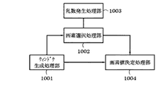
図11は、本発明に係る画像処理装置におけるノイズ除去処理機能を説明するブロック図であり、図5に示した画像処理タスク8009の一例である。
【0096】
図11において、ウインドウ生成処理部1001では、ノイズ除去処理を行うためのウインドウを生成する。本実施形態では、ウィンドウサイズを9×9ピクセルとする。
【0097】
画素選択処理部1002では、乱数発生処理部1003において生成した乱数から、ウインドウ内のランダムな画素を選択する。画素値決定処理部1004では、しきい値との比較により、ターゲットピクセルの画素値を決定する。
【0098】
図12は、本発明に係る画像処理装置における第2のデータ処理手順の一例を示すフローチャートであり、あるラスタ(y)におけるノイズ除去処理手順に対応する。なお、S1101〜S1106は各ステップを示す。
【0099】
まず、ステップS1101では、乱数発生処理部1003により2つの乱数を発生させる。なお、乱数の発生アルゴリズムについては、ここでは限定しないが、確率的に一様であることが望ましい。
【0100】
次に、ステップS1102においては、発生した乱数からウィンドウサイズを超えない位置情報を生成する。例えばウインドウが9×9の場合、注目画素を中心とすると、
−4≦a≦4
−4≦b≦4
となるように、発生させた乱数から余剰計算を用いて設定する。
【0101】
次に、ステップS1103では、決定したa、bの値を用いて、以下の第(1)式に基づく比較を行う。
【0102】
|IY(i,j)−IY(i+a,j+b)|<Th_Y かつ
|ICb(i,j)−ICb(i+a,j+b)|<Th_Cb かつ
|ICr(i,j)−ICr(i+a,j+b)|<Th_Cr・・・(1)
ここで、IY(i,j)、ICb(i,j)、ICr(i,j)はそれぞれ、画像のxカラム、yラスター位置の輝度Y、色差Cb、色差Cr成分を表している。
【0103】
また、TH_Y、TH_Cb、TH_Crは、ターゲット画素(i+a,j+b)との差分との判定を行うしきい値で、予め設定しておく。このしきい値が大きいほど、ノイズ除去の強度が上がる。
【0104】
そして、ステップS1103の条件を満たすと判断した場合は、ステップS1104へと進み、出力画素値FY(i,j)、FCb(i,j)、FCr(i,j)は、下記第(2)式により
FY(i,j)=IY(i,j)+D
FCb(i,j)=ICb(i+a,j+b)
FCr(i,j)=ICr(i+a,j+b)・・・・・・(2)
となる。ここで輝度成分については、ターゲット画素の輝度に置き換えず、注目画素の輝度値に固定値Dを足し合わせている。これは、輝度成分に対する目の感度が高いため、大きく値を変えない方が、ノイズ除去の効果が上がるためである。
【0105】
一方、ステップS1103の条件を満たさないと判断した場合は、ステップS1105へと進み、
FY(i,j)=IY(i,j)
FCb(i,j)=ICb(i,j)
FCr(i,j)=ICr(i,j)
とする。つまり、注目画素の値から変化をさせない。
【0106】
そして、ステップS1106で、これらの処理を全ての画素に行ったかを判定し、終わっていないと判定した場合は、i=i+1として、ステップS1101へ戻り、繰り返し上記処理を行う。
【0107】
一方、ステップS1106で、全てのカラムについて実行したと判定した場合は、このラスタ(j)については終了となる。
【0108】
以上の処理を全てのラスタについて施すことにより、ノイズ除去処理が実行された画像データY’Cb’Cr’が得られる。
【0109】
図13は、本発明に係る画像処理装置における色処理部の機能処理モデルを説明するブロック図であり、本実施形態のJPEGデコードからノイズ除去、色変換処理までのバッファの使用方法を示すモデルに対応する。
【0110】
図13において、132は画像補正処理部で、デコードが必要と判定された場合、画像補正バッファ134のデコードデータ格納先のアドレスを設定し、デコード処理部131にデコード要求をする。デコード要求を受けたデコード処理部131は、デコード処理を実行し、設定されたアドレスにデコードデータを書き出す。画像補正バッファ134のライン数Lは、1回のデコード時に作成されるライン数をN、画像補正処理に必要なライン数をMとした時、
L=M+(N−1)・・・・・・・(3)
で求められる。上式で求められるLは最もメモリを少なくする場合であり、この値より多くすることももちろん可能である。
【0111】
本実施形態の場合、1回のデコード時に作成されるライン数Nを8、画像補正処理に必要なライン数Mを9としているので、画像補正バッファ134のライン数Lは、9+(8−1)=16となる。
【0112】
必要なラスタデータが揃った後、画像補正処理部132は補正処理を実行し、結果を色変換バッファ135に書き出す。色変換処理部133では、色変換バッファ135内のデータについて、色変換処理を行い、上書きをして終了となる。
【0113】
以下、図13に示した画像補正バッファ134の詳細を説明する。
【0114】
図14は、図13に示した画像補正バッファ134の詳細構成を説明する図であり、バッファのサイズとしては、ラスタ方向には、上述した16ラスタ分、カラム(横)方向にはWとする。
【0115】
なお、Wは、対応する画像サイズに依存するものであり、横1600×縦1200ピクセルを持つ、いわゆる2メガピクセルと呼ばれるデジタルカメラで撮影した画像であれば、1600となる。さらに1画素あたり、Y,Cb,Crの3成分のデータが格納されているので、W=1600×3=4800となる。メモリ容量としては、各成分8ビットとすれば、16×4800=76800[Byte]が必要とされる。
【0116】
次に、処理時のメモリの使用方法について、図15を用いて説明する。
【0117】
図15は、図14に示した画像補正バッファ134の使用例を説明する図である。
【0118】
図15の(a)は、7ライン目の処理が実行されている時を示している。7ラインから上下それぞれ4ラインずつ、3〜11ラインをウインドウとして、ノイズ除去の処理が行われ、順次色変換バッファ(図示なし)へと書き込みを行っていく。7ライン目の全ての画素について処理が完了したら、次の8ライン目へと着目ラインが移動する。これらの処理が繰り返し行われ、図15の(b)では、着目ラインが12ライン目になった状態を示している。
【0119】
この場合、ウインドウは8〜16ラインとなる。12ライン目のノイズ除去処理が終了し、13ライン目へと進んだ場合(図15の(c))、ウインドウのスコープは、着目ライン上部は9〜11の4ライン分、下部は13〜16の3ラインと1の1ラインとなる。この場合、1ライン目に格納されているのは、既に処理が完了したラスタデータとなっているため、新たなデコードが必要となる。デコード先のアドレスを1ライン目の先頭アドレスとし、デコードの要求を行う。デコードは8ライン単位で行われるので、1〜8ラインの領域にデコードされた新しい画像データが格納される。
【0120】
この後、着目ラインが16ライン目と進み、そこでの処理が完了したら、着目ラインは1ライン目へと戻される(図15の(d))。そして、図15の(e)に示しているように、5ライン目へと着目ラインが進んだときに、ウインドウが1〜9ラインとなり、9ライン目に新しいラスタデータが必要となる。デコード先のポインタに9ライン目の先頭アドレスを設定し、デコード要求を発行する。デコードデータは、9〜16ライン目に格納され、処理が続けられる。
【0121】
このように、実行ライン数Jとしたときに、バッファ上0〜Lでの着目ラインRは、R=J%Lとして表される。なお、式中の%は剰余算を示す。
【0122】
また、デコード要求を行うタイミングは、デコードした回数をDとしたとき、デコードで生成されたライン数Sは、ライン数S=D×Nより決定され、要求されるライン数Tは、ライン数T=J+(M−1)÷2より決定され、要求されるライン数がデコードで生成されたライン数を超えたとき、つまり、(T>S)が真となったときに、デコード要求が行われる。その際、設定するデコード先のアドレスAは、A=(S+1)%Lより算定される。
【0123】
これらの演算処理によって得られたものがラインの先頭アドレスとなる。
【0124】
この方法を用いることにより、従来では上述したように量子化処理までに、4回のメモリアクセス(書き込み処理)が必要とされていたのに対して、本処理では、(1)デコーダのデコードバッファへの書き込み、(2)ノイズ除去処理後のラスタデータの色変換バッファへの書き込み、(3)色変換処理後の色変換バッファへの上書き等のように、3回の書き込み処理で実現出来る。
【0125】
また、バッファ容量としても従来のようにデコードバッファと画像補正バッファを独立に確保していた場合では、1600×8×3(デコードバッファ)+1600×9×3(画像補正バッファ)=81600[Byte]必要だったものが、上記したように画像補正バッファの76800[Byte]となり、メモリ資源を節減できる。
【0126】
このように、L=M+(N−1)で示されるライン数の画像補正バッファを確保して、そこでリングバッファの使い方を利用することで、画像補正処理において、メモリへのアクセス回数を減らし高速化を図り、必要なメモリ容量の削減を実現出来る。
【0127】
〔第2実施形態〕
第2実施形態としては、画像補正処理例として、マトリクスを利用したぼかし処理の場合を示す。基本的な処理の流れは、図10および図13と同様である。
【0128】
図16は、本発明の第2実施形態を示す画像処理装置で利用するマトリクスの構成を説明する図である。
【0129】
なお、ぼかし処理の方法としては、図16に示す3×3マトリクスのLPF処理を利用する。着目画素の画素データは、隣接する周囲8ピクセルの画素値の平均値(A+B+C+D+E+F+G+H)÷8から求められる。この処理を全ての画素について行うことで、ぼかし処理が実行される。
【0130】
図17は、本発明に係る画像処理装置による画像補正バッファのメモリ使用方法例を示す図であり、実際に動作しているときのメモリ状態のモデル図を示す。
【0131】
なお、一度にデコードで生成されるラスタ数Nを8ラインとすると、バッファのライン数Lは、上記第(3)式より、L=3+(8−1)=10となる。
【0132】
図17の(a)は、処理が開始され、2ライン目の処理を行う場合である。この状態では、1〜8ライン目に、デコードされたラスタデータが格納されている。この後、上述したLPFを使ったフィルタリング処理が実行され、2ライン目の全てのピクセルについて処理が行われると、着目ラスタが一つ進められる。これを繰り返し行い、着目ラスタが8ライン目になった場合を、図17の(b)に示す。このとき、SはS=1×8=8と決定され、TはT=8+(3−1)÷2=9と決定され、(T>S)が真となるので、デコード要求が行われる。この時設定される、デコード格納先の先頭アドレスAは、A=(8+1)%10=9と求められる。
【0133】
しかし、この場合、デコードが8ラスタ行われるので、9+8=17のバッファまで進んでしまい、デコード後、画像補正バッファへ書き込みを行う際に、メモリ破壊を起こしてしまう。そこで、予め、A+N>Lの判定を行い、もしこの条件式を満たす場合は、最初の(L−A+1)ラスタデータ→Aライン目の先頭アドレスとし、残りA−(L−A+1)ラスタデータ→1ライン目の先頭アドレスの条件をセットし、デコードの要求を行う。
【0134】
以上のような処理を行うことにより、第1実施形態と同様に、メモリアクセス回数および使用メモリ容量の削減を、フィルタリング処理においても実現出来る。
【0135】
以下、図18に示すメモリマップを参照して本発明に係る画像処理装置で読み取り可能なデータ処理プログラムの構成について説明する。
【0136】
図18は、本発明に係る画像処理装置で読み取り可能な各種データ処理プログラムを格納する記憶媒体のメモリマップを説明する図である。
【0137】
なお、特に図示しないが、記憶媒体に記憶されるプログラム群を管理する情報、例えばバージョン情報,作成者等も記憶され、かつ、プログラム読み出し側のOS等に依存する情報、例えばプログラムを識別表示するアイコン等も記憶される場合もある。
【0138】
さらに、各種プログラムに従属するデータも上記ディレクトリに管理されている。また、各種プログラムをコンピュータにインストールするためのプログラムや、インストールするプログラムが圧縮されている場合に、解凍するプログラム等も記憶される場合もある。
【0139】
本実施形態における図10,図12に示す機能が外部からインストールされるプログラムによって、ホストコンピュータにより遂行されていてもよい。そして、その場合、CD−ROMやフラッシュメモリやFD等の記憶媒体により、あるいはネットワークを介して外部の記憶媒体から、プログラムを含む情報群を出力装置に供給される場合でも本発明は適用されるものである。
【0140】
以上のように、前述した実施形態の機能を実現するソフトウエアのプログラムコードを記録した記憶媒体を、システムあるいは装置に供給し、そのシステムあるいは装置のコンピュータ(またはCPUやMPU)が記憶媒体に格納されたプログラムコードを読出し実行することによっても、本発明の目的が達成されることは言うまでもない。
【0141】
この場合、記憶媒体から読み出されたプログラムコード自体が本発明の新規な機能を実現することになり、そのプログラムコードを記憶した記憶媒体は本発明を構成することになる。
【0142】
従って、プログラムの機能を有していれば、オブジェクトコード、インタプリタにより実行されるプログラム、OSに供給するスクリプトデータ等、プログラムの形態を問わない。
【0143】
プログラムを供給するための記憶媒体としては、例えばフレキシブルディスク、ハードディスク、光ディスク、光磁気ディスク、MO、CD−ROM、CD−R、CD−RW、磁気テープ、不揮発性のメモリカード、ROM、DVDなどを用いることができる。
【0144】
この場合、記憶媒体から読出されたプログラムコード自体が前述した実施形態の機能を実現することになり、そのプログラムコードを記憶した記憶媒体は本発明を構成することになる。
【0145】
その他、プログラムの供給方法としては、クライアントコンピュータのブラウザを用いてインターネットのホームページに接続し、該ホームページから本発明のコンピュータプログラムそのもの、もしくは、圧縮され自動インストール機能を含むファイルをハードディスク等の記録媒体にダウンロードすることによっても供給できる。また、本発明のプログラムを構成するプログラムコードを複数のファイルに分割し、それぞれのファイルを異なるホームページからダウンロードすることによっても実現可能である。つまり、本発明の機能処理をコンピュータで実現するためのプログラムファイルを複数のユーザに対してダウンロードさせるWWWサーバやftpサーバ等も本発明の請求項に含まれるものである。
【0146】
また、本発明のプログラムを暗号化してCD−ROM等の記憶媒体に格納してユーザに配布し、所定の条件をクリアしたユーザに対し、インターネットを介してホームページから暗号化を解く鍵情報をダウンロードさせ、その鍵情報を使用することにより暗号化されたプログラムを実行してコンピュータにインストールさせて実現することも可能である。
【0147】
また、コンピュータが読み出したプログラムコードを実行することにより、前述した実施形態の機能が実現されるだけでなく、そのプログラムコードの指示に基づき、コンピュータ上で稼働しているOS(オペレーティングシステム)等が実際の処理の一部または全部を行い、その処理によって前述した実施形態の機能が実現される場合も含まれることは言うまでもない。
【0148】
さらに、記憶媒体から読み出されたプログラムコードが、コンピュータに挿入された機能拡張ボードやコンピュータに接続された機能拡張ユニットに備わるメモリに書き込まれた後、そのプログラムコードの指示に基づき、その機能拡張ボードや機能拡張ユニットに備わるCPU等が実際の処理の一部または全部を行い、その処理によって前述した実施形態の機能が実現される場合も含まれることは言うまでもない。
【0149】
本発明は上記実施形態に限定されるものではなく、本発明の趣旨に基づき種々の変形(各実施形態の有機的な組合せを含む)が可能であり、それらを本発明の範囲から排除するものではない。
【0150】
本発明の様々な例と実施形態を示して説明したが、当業者であれば、本発明の趣旨と範囲は、本明細書内の特定の説明に限定されるのではない。
【0151】
上記実施形態によれば、JPEG画像の復号化により、生成されるマルチラスタに対しての画像補正処理において、メモリアクセス頻度を低減すること、メモリの使用容量の削減を実現することが可能となる。メモリアクセス回数が減ることで、画像補正処理の高速化の効果が実現出来る。
【0152】
【発明の効果】
以上説明したように、本発明によれば、画像データに対する画像処理時に、確保すべき記憶領域を最小限とし、かつ、画像処理結果を得るまでに要する記憶領域に対するアクセス処理回数を大幅に削減して処理時間を短縮して効率よく画像処理を行えるという効果を奏する。
【図面の簡単な説明】
【図1】本発明の第1実施形態を示す画像処理装置の一例を示す外観斜視図である。
【図2】図1に示した操作パネルの構成を説明する概略平面図である。
【図3】本発明の第1実施形態を示す画像処理装置の構成を説明するブロック図である。
【図4】図3に示したASICの詳細構成を示すブロック図である。
【図5】図4に示した画像処理装置における各デバイスと機能モジュールとの対応を説明するブロック図である。
【図6】図5に示した画像処理タスクの機能処理を説明するブロック図である。
【図7】図6に示した色変換処理が参照するLUTの一例を示す図である。
【図8】図6に示した色変換処理における四面体補間法の概念を説明する図である。
【図9】本発明に係る画像処理装置における誤差拡散法における、誤差分配方法を示す図である。
【図10】本発明に係る画像処理装置における第1のデータ処理手順の一例を示すフローチャートである。
【図11】本発明に係る画像処理装置におけるノイズ除去処理機能を説明するブロック図である。
【図12】本発明に係る画像処理装置における第2のデータ処理手順の一例を示すフローチャートである。
【図13】本発明に係る画像処理装置における色処理部の機能処理モデルを説明するブロック図である。
【図14】図13に示した画像補正バッファの詳細構成を説明する図である。
【図15】図14に示した画像補正バッファの使用例を説明する図である。
【図16】本発明の第2実施形態を示す画像処理装置で利用するマトリクスの構成を説明する図である。
【図17】本発明に係る画像処理装置による画像補正バッファのメモリ使用方法例を示す図である。
【図18】本発明に係る画像処理装置で読み取り可能な各種データ処理プログラムを格納する記憶媒体のメモリマップを説明する図である。
【図19】従来の画像処理装置のデータ処理状態を説明するブロック図である。
【図20】図19に示した色処理部におけるデータ処理の詳細を説明するブロック図である。
【符号の説明】
131 デコード処理部
132 画像補正処理部
133 色変換処理部
134 画像補正バッファ
135 色変換バッファ
136 量子化処理部[0001]
BACKGROUND OF THE INVENTION
The present invention relates to an image processing apparatus and image processing method for performing predetermined image processing on image data, a storage medium storing a computer-readable program, and a program.
[0002]
[Prior art]
In recent years, digital cameras have rapidly spread in place of conventional silver halide cameras. This is considered to be caused by the fact that personal computers (hereinafter referred to as PCs) have permeated many people, so that digitized image data can be handled more easily.
[0003]
In addition, the advancement of semiconductor manufacturing technology has boosted the high pixel and high image quality of images taken with digital cameras.
[0004]
In addition, with the recent increase in functionality of mobile devices such as mobile phones and PDAs, those equipped with digital cameras have emerged, and even those who do not have a PC have more opportunities to access digital photographs.
[0005]
For these users, printers capable of printing without connecting to a PC have been introduced so that printing can be performed without using a PC. This is realized by providing the printer main body with the image processing function performed by the PC on the host side.
[0006]
FIG. 19 is a block diagram for explaining a data processing state of a conventional image processing apparatus, and shows an example of image processing performed by a printer as an image processing apparatus, for example.
[0007]
19,
[0008]
A
[0009]
An image
[0010]
The subsequent color
[0011]
The image data converted into the ink color is sent to the
[0012]
Examples of the quantization processing method include an error diffusion method and a dither method using a matrix. By these processes, the ink color data of the printer is transmitted to the recording control unit (not shown) of the printer as printable gradation data.
[0013]
FIG. 20 is a block diagram illustrating details of data processing in the
[0014]
In FIG. 20,
[0015]
For example, it is 17 lines for CCD noise reduction processing, which will be described later, and 3 lines for filter processing using a 3 × 3 matrix for JPEG decoded data described in Patent Document 1. The corrected data is written to the
[0016]
The color
[0017]
After the image
[0018]
As described above, even when data for 8 lines is generated by one decoding process such as a JPEG image, the
[0019]
Moreover, patent documents 1 to 3 are disclosed as this type of patent document.
[0020]
[Patent Document 1]
JP-A-10-32709
[0021]
[Patent Document 2]
JP 2000-156830 A
[0022]
[Patent Document 3]
JP-A-6-217094
[0023]
[Problems to be solved by the invention]
Since the conventional image processing apparatus is configured as described above, in the case of an embedded system such as an image processing function added to the printer body, its memory capacity, CPU, internal bus speed, etc. Performance is often very poor.
[0024]
When correction is performed on an image typified by JPEG that is generated by multi-raster, access to the buffer memory as shown in FIG. 20 described above is performed, but focusing on the writing process, writing to the decoding buffer, image Four writing processes occur before writing to the correction buffer, writing the corrected data to the color conversion buffer, overwriting the post-color conversion data to the color conversion buffer, and the quantization process.
[0025]
In the case of a system such as a PC that has a large-capacity memory that can be accessed at high speed, this is not a serious problem.
[0026]
However, in cases where the memory capacity is severely limited in embedded systems and in systems where memory access, especially access to write processing is slow, it is important how to reduce write processing to reduce memory capacity and speed. It becomes a problem.
[0027]
In Patent Document 2, data that has been decoded and subjected to predetermined image processing is stored in a primary buffer that temporarily stores the data to increase the speed. However, when the memory capacity is increased, the data is stored in the primary buffer. The writing process occurs.
[0028]
In addition, Patent Document 3 has a circular buffer (ring buffer), which achieves high-speed output of a plurality of pages while keeping the buffer small and efficient. The image correction to be performed is not taken into consideration. In addition, there is a problem that the number of times of access remains as a problem.
[0029]
The present invention has been made to solve the above problems, and the object of the present invention is, PaintingDuring image processing of image data, the storage area to be secured is minimized, and the number of access processes to the storage area required to obtain the image processing result is greatly reduced to shorten the processing time and efficiently perform image processing. Can doStructureThe purpose is to provide.
[0030]
[Means for Solving the Problems]
Main departureTomorrow,Image correction means for performing image correction processing by performing window processing for referring to the pixel of interest and surrounding pixels on the decoded image data, and the number of lines obtained by the decoding N , The number of lines used in the window processing M If (1) Number of lines calculated by formula L Area securing means for securing a storage area for the image data of L = M + (N-1) ... (1) While executing the image correction process using the image data stored in the secured storage area, the process target line is advanced one by one, and the image correction is performed next to the image correction for the image data of the lowest line in the storage area. Line step means for processing the image data of the upper line, and the number of times of decoding the image data D , The number of lines on which the image correction processing is executed J age, (2) formula J + (M − 1) ÷ 2 > D × N ... (2) Is satisfied, of the storage area, ((D × N + 1)% L) The second line ( % And image decoding means for performing the decoding in order to store the image data from the remainder calculation).
[0038]
DETAILED DESCRIPTION OF THE INVENTION
[First Embodiment]
Hereinafter, preferred embodiments of the present invention will be described in detail with reference to the accompanying drawings. In this embodiment, not only a printer capable of printing from a normal PC but also an image taken with a digital camera having a PC card slot and recorded on the PC card is possible. A recording apparatus (photo direct printer apparatus) that employs an inkjet method as a recording method will be described as an example.
[0039]
Hereinafter, preferred embodiments of the present invention will be described in detail with reference to the accompanying drawings.
[0040]
FIG. 1 is an external perspective view showing an example of an image processing apparatus according to the first embodiment of the present invention, and corresponds to an example of a photo
[0041]
In FIG. 1, the main body that forms the outer shell of the photo
[0042]
The
[0043]
Further, one end of the
[0044]
In addition, the
[0045]
One end of the
[0046]
A
[0047]
The structure of the
[0048]
[0049]
[0050]
FIG. 2 is a schematic plan view illustrating the configuration of
[0051]
In FIG. 2, the liquid
[0052]
The items displayed here are the first photo number of the range to be printed, the designated frame number (start / -designate), the last photo number of the range to be printed (end), the number of copies (number of copies), and used for printing Type of paper (recording sheet) to be printed (paper type), setting of the number of photos to be printed on one sheet (layout), specification of print quality (quality), and whether to print the date of shooting (date printing) ), Designation of whether or not to print a photograph (image correction), display of the number of sheets necessary for printing (number of sheets), and the like.
[0053]
These items are selected or designated using the
[0054]
[0055]
FIG. 3 is a block diagram illustrating the configuration of the image processing apparatus according to the first embodiment of the present invention, and corresponds to the configuration of the main part related to the control of the photo
[0056]
In FIG. 3,
[0057]
[0058]
[0059]
[0060]
As a result, the
[0061]
Note that the exchange of signals between the
[0062]
FIG. 4 is a block diagram showing a detailed configuration of the
[0063]
In FIG. 4,
[0064]
[0065]
[0066]
[0067]
These control programs are configured in a multitask format in which each functional module is converted into a task. FIG. 5 shows the main task configuration.
[0068]
FIG. 5 is a block diagram for explaining the correspondence between each device and the functional module in the image processing apparatus shown in FIG.
[0069]
In FIG. 5,
[0070]
[0071]
[0072]
[0073]
[0074]
[0075]
FIG. 6 is a block diagram illustrating functional processing of the
[0076]
In the
[0077]
R = Y + 1.402 (Cr-128)
G = Y−0.34414 (Cb−128) −0.71414 (Cr−128)
B = Y + 1.772 (Cb-128)
However, YCbCr is 0 to 255 in 8 bits. As a result, the image data converted into the RGB format is converted into ink colors by the
[0078]
FIG. 7 is a diagram illustrating an example of the LUT referred to by the
[0079]
The LUT prepared in advance describes C, M, Y, K, LC, and LM signal values corresponding to 4913 points obtained by dividing the RGB values as shown in FIG. The C, M, Y, K, LC, and LM values corresponding to the input RGB values are referenced. If the RGB value is between 16 divisions, the R'G'B 'value is obtained by interpolation processing.
[0080]
Hereinafter, a tetrahedral interpolation method will be described as an example of the interpolation method with reference to FIG.
[0081]
FIG. 8 is a diagram for explaining the concept of the tetrahedral interpolation method in the
[0082]
Note that the tetrahedral interpolation method is linear interpolation using four grid points with a unit of division in a three-dimensional space as a tetrahedron.
[0083]
As the procedure, first, as shown in FIG. 8A, division into tetrahedrons is performed. Then, the tetrahedron to which the target point p belongs is determined. The four vertices of the tetrahedron are defined as p0, p1, p2, and p3, and are divided into smaller tetrahedrons as shown in FIG. Further, if the conversion values of the extension points are f (p0), f (p1), f (p2), and f (p3), respectively, the following equation 1 is obtained.
[0084]
[Expression 1]
[0085]
Here, referring back to FIG. 6, the data converted into the ink color by the
[0086]
In the present embodiment, a case of an inkjet printer having 1 bit / binary of recording (1) / non-recording (0) is considered. Here, the quantization method is an error diffusion method that is optimal for the quantization of photographic images. The input signal is 8 bits from 0 to 255.
[0087]
FIG. 9 is a diagram showing an error distribution method in the error diffusion method in the image processing apparatus according to the present invention. When the signal value of the target pixel is L (0 ≦ L ≦ 255), it is compared with the threshold value TH. Depending on its size,
L> TH ... 1 (record)
L ≦ TH ・ ・ ・ ・ ・ ・ 0 (Non-recording)
It is determined. The error E (= L−TH) generated at that time is distributed to surrounding pixels according to the distribution coefficient shown in FIG. By performing this process for all pixels and all ink colors C, M, Y, K, LC, and LM, 1-bit image data colors C ′, M, Y, K ′, LC ′, and LM ′ Quantized to
[0088]
Next, the details of the image correction processing for performing the method of using the memory, which is a feature of this embodiment, will be described with reference to the flowchart shown in FIG.
[0089]
FIG. 10 is a flowchart showing an example of a first data processing procedure in the image processing apparatus according to the present invention, and corresponds to a raster-unit correction processing procedure. S1201 to S1205 indicate each step. This step is associated with the
In addition, in order to execute the correction process for each raster, one new line is required from the process performed last time.
[0090]
First, in step S1201, it is determined whether or not decoding is necessary to obtain it. If it is determined that it is not necessary, the process proceeds to step S1202, and correction processing is executed.
[0091]
On the other hand, if it becomes necessary in step S1201, an output destination address for outputting decoded data is set in step S1203, and decoding processing is executed in step S1204. Then, it progresses to step S1202 and a correction process is performed.
[0092]
After the correction process is executed, in step S1205, it is determined whether the process has been executed for all raster data. If it is determined that the process has been performed, the process ends. In this case, the attention raster is advanced, and the process returns to step S1201.
[0093]
Next, specific contents of the correction process will be described.
[0094]
In the first embodiment, processing for removing low-frequency noise caused by the CCD of the
[0095]
FIG. 11 is a block diagram illustrating a noise removal processing function in the image processing apparatus according to the present invention, and is an example of the
[0096]
In FIG. 11, a window
[0097]
The pixel
[0098]
FIG. 12 is a flowchart showing an example of a second data processing procedure in the image processing apparatus according to the present invention, and corresponds to a noise removal processing procedure in a certain raster (y). S1101 to S1106 indicate each step.
[0099]
First, in step S1101, the random number
[0100]
Next, in step S1102, position information that does not exceed the window size is generated from the generated random number. For example, if the window is 9x9,
-4 ≦ a ≦ 4
-4 ≦ b ≦ 4
From the generated random number, it is set using surplus calculation.
[0101]
Next, in step S1103, a comparison based on the following expression (1) is performed using the determined values a and b.
[0102]
| IY (i, j) −IY (i + a, j + b) | <Th_Y and
| ICb (i, j) -ICb (i + a, j + b) | <Th_Cb and
| ICr (i, j) -ICr (i + a, j + b) | <Th_Cr (1)
Here, IY (i, j), ICb (i, j), and ICr (i, j) represent the x column of the image, the luminance Y at the y raster position, the color difference Cb, and the color difference Cr component, respectively.
[0103]
Further, TH_Y, TH_Cb, and TH_Cr are threshold values that are determined in advance as differences from the target pixel (i + a, j + b). The greater this threshold, the higher the noise removal strength.
[0104]
If it is determined that the condition of step S1103 is satisfied, the process proceeds to step S1104, and the output pixel values FY (i, j), FCb (i, j), FCr (i, j) are the following (2). By formula
FY (i, j) = IY (i, j) + D
FCb (i, j) = ICb (i + a, j + b)
FCr (i, j) = ICr (i + a, j + b) (2)
It becomes. Here, the luminance component is not replaced with the luminance of the target pixel, but the fixed value D is added to the luminance value of the target pixel. This is because the sensitivity of the eyes with respect to the luminance component is high, and the effect of noise removal increases if the value is not changed greatly.
[0105]
On the other hand, if it is determined that the condition of step S1103 is not satisfied, the process proceeds to step S1105,
FY (i, j) = IY (i, j)
FCb (i, j) = ICb (i, j)
FCr (i, j) = ICr (i, j)
And That is, the value of the target pixel is not changed.
[0106]
In step S1106, it is determined whether or not these processes have been performed on all the pixels. If it is determined that the process has not been completed, i = i + 1 is set, and the process returns to step S1101 to repeat the above process.
[0107]
On the other hand, if it is determined in step S1106 that the process has been executed for all columns, the raster (j) is ended.
[0108]
By performing the above processing on all the rasters, image data Y′Cb′Cr ′ on which noise removal processing has been performed is obtained.
[0109]
FIG. 13 is a block diagram for explaining a functional processing model of the color processing unit in the image processing apparatus according to the present invention. The model illustrates a buffer usage method from JPEG decoding to noise removal and color conversion processing according to this embodiment. Correspond.
[0110]
In FIG. 13,
L = M + (N−1) (3)
Is required. L obtained by the above equation is the case where the memory is minimized, and it is of course possible to increase it from this value.
[0111]
In the present embodiment, since the number N of lines created at the time of one decoding is 8 and the number M of lines necessary for image correction processing is 9, the number L of lines in the
[0112]
After the necessary raster data is prepared, the image
[0113]
Details of the
[0114]
FIG. 14 is a diagram for explaining the detailed configuration of the
[0115]
Note that W depends on the corresponding image size, and is 1600 if it is an image taken by a so-called 2 megapixel digital camera having horizontal 1600 × vertical 1200 pixels. Further, since data of three components Y, Cb, and Cr is stored per pixel, W = 1600 × 3 = 4800. As the memory capacity, if each component is 8 bits, 16 × 4800 = 76800 [Byte] is required.
[0116]
Next, a method of using the memory during processing will be described with reference to FIG.
[0117]
FIG. 15 is a diagram for explaining an example of use of the
[0118]
FIG. 15A shows the time when the process on the seventh line is being executed. Noise removal processing is performed with 4 lines from 7 lines up and down, and 3 to 11 lines as windows, and writing is sequentially performed to a color conversion buffer (not shown). When the processing is completed for all the pixels on the seventh line, the target line moves to the next eighth line. These processes are repeated, and FIG. 15B shows a state in which the target line is the 12th line.
[0119]
In this case, the window has 8 to 16 lines. When the noise removal process for the 12th line is completed and the process proceeds to the 13th line ((c) in FIG. 15), the scope of the window is the four
[0120]
Thereafter, the line of interest advances to the 16th line, and when the process is completed, the line of interest is returned to the first line ((d) in FIG. 15). As shown in FIG. 15E, when the line of interest advances to the fifth line, the window becomes 1 to 9 lines, and new raster data is required for the 9th line. The leading address of the ninth line is set in the decoding destination pointer, and a decoding request is issued. The decoded data is stored in the 9th to 16th lines, and the processing is continued.
[0121]
As described above, when the number of execution lines is J, the line of interest R at 0 to L on the buffer is expressed as R = J% L. In addition,% in a formula shows a remainder calculation.
[0122]
In addition, when the number of times of decoding is set to D, the number of lines S generated by decoding is determined from the number of lines S = D × N, and the required number of lines T is the number of lines T = J + (M−1) ÷ 2, and when the number of requested lines exceeds the number of lines generated by decoding, that is, when (T> S) becomes true, a decoding request is made. Is called. At this time, the decoding destination address A to be set is calculated from A = (S + 1)% L.
[0123]
What is obtained by these arithmetic processes is the head address of the line.
[0124]
By using this method, the memory access (write process) has been required four times before the quantization process as described above, whereas in this process, (1) the decoder buffer of the decoder is used. This can be realized by three writing processes, such as writing to the color conversion buffer, (2) writing the raster data after the noise removal process to the color conversion buffer, and (3) overwriting the color conversion buffer after the color conversion process.
[0125]
Further, in the case where the decoding buffer and the image correction buffer are secured independently as in the conventional case, 1600 × 8 × 3 (decoding buffer) + 1600 × 9 × 3 (image correction buffer) = 81600 [Byte] What is needed is 76800 [Bytes] of the image correction buffer as described above, and memory resources can be saved.
[0126]
In this way, by securing an image correction buffer having the number of lines represented by L = M + (N−1) and using the ring buffer there, the number of accesses to the memory can be reduced and high speed can be achieved in image correction processing. The required memory capacity can be reduced.
[0127]
[Second Embodiment]
In the second embodiment, a blurring process using a matrix is shown as an example of the image correction process. The basic processing flow is the same as in FIGS.
[0128]
FIG. 16 is a diagram illustrating the configuration of a matrix used in the image processing apparatus according to the second embodiment of the present invention.
[0129]
Note that the 3 × 3 matrix LPF processing shown in FIG. 16 is used as the blurring processing method. Pixel data of the pixel of interest is obtained from an average value (A + B + C + D + E + F + G + H) ÷ 8 of pixel values of adjacent eight neighboring pixels. By performing this process for all the pixels, the blurring process is executed.
[0130]
FIG. 17 is a diagram showing an example of a method of using the memory of the image correction buffer by the image processing apparatus according to the present invention, and shows a model diagram of the memory state during actual operation.
[0131]
If the number N of rasters generated by decoding at a time is 8 lines, the number L of buffer lines is L = 3 + (8−1) = 10 from the above equation (3).
[0132]
(A) of FIG. 17 is a case where a process is started and the process of the 2nd line is performed. In this state, decoded raster data is stored in the first to eighth lines. Thereafter, the filtering process using the LPF described above is executed, and when the process is performed for all the pixels on the second line, the focused raster is advanced by one. FIG. 17B shows a case where this process is repeated and the focused raster reaches the eighth line. At this time, S is determined as S = 1 × 8 = 8, T is determined as T = 8 + (3-1) ÷ 2 = 9, and (T> S) is true, so a decoding request is made. . The leading address A of the decoding storage destination set at this time is obtained as A = (8 + 1)% 10 = 9.
[0133]
However, in this case, since decoding is performed by 8 rasters, the process proceeds to a buffer of 9 + 8 = 17, and memory is destroyed when writing to the image correction buffer after decoding. Therefore, it is determined in advance that A + N> L, and if this conditional expression is satisfied, the first (LA + 1) raster data → the start address of the A line and the remaining A− (LA + 1) raster data → The condition of the first address on the first line is set and a decoding request is made.
[0134]
By performing the processing as described above, it is possible to reduce the number of memory accesses and the memory capacity used in the filtering processing as in the first embodiment.
[0135]
The configuration of a data processing program that can be read by the image processing apparatus according to the present invention will be described below with reference to the memory map shown in FIG.
[0136]
FIG. 18 is a diagram illustrating a memory map of a storage medium that stores various data processing programs that can be read by the image processing apparatus according to the present invention.
[0137]
Although not particularly illustrated, information for managing a program group stored in the storage medium, for example, version information, creator, etc. is also stored, and information depending on the OS on the program reading side, for example, a program is identified and displayed. Icons may also be stored.
[0138]
Further, data depending on various programs is also managed in the directory. In addition, a program for installing various programs in the computer, and a program for decompressing when the program to be installed is compressed may be stored.
[0139]
The functions shown in FIGS. 10 and 12 in this embodiment may be performed by a host computer by a program installed from the outside. In this case, the present invention is applied even when an information group including a program is supplied to the output device from a storage medium such as a CD-ROM, a flash memory, or an FD, or from an external storage medium via a network. Is.
[0140]
As described above, a storage medium storing software program codes for realizing the functions of the above-described embodiments is supplied to the system or apparatus, and the computer (or CPU or MPU) of the system or apparatus stores the storage medium in the storage medium. It goes without saying that the object of the present invention can also be achieved by reading and executing the programmed program code.
[0141]
In this case, the program code itself read from the storage medium realizes the novel function of the present invention, and the storage medium storing the program code constitutes the present invention.
[0142]
Therefore, as long as it has the function of the program, the form of the program such as an object code, a program executed by an interpreter, or script data supplied to the OS is not limited.
[0143]
As a storage medium for supplying the program, for example, a flexible disk, hard disk, optical disk, magneto-optical disk, MO, CD-ROM, CD-R, CD-RW, magnetic tape, nonvolatile memory card, ROM, DVD, etc. Can be used.
[0144]
In this case, the program code itself read from the storage medium realizes the functions of the above-described embodiments, and the storage medium storing the program code constitutes the present invention.
[0145]
As another program supply method, a browser of a client computer is used to connect to a homepage on the Internet, and the computer program itself of the present invention or a compressed file including an automatic installation function is stored on a recording medium such as a hard disk from the homepage. It can also be supplied by downloading. It can also be realized by dividing the program code constituting the program of the present invention into a plurality of files and downloading each file from a different homepage. That is, a WWW server, an ftp server, and the like that allow a plurality of users to download a program file for realizing the functional processing of the present invention on a computer are also included in the claims of the present invention.
[0146]
In addition, the program of the present invention is encrypted, stored in a storage medium such as a CD-ROM, distributed to users, and key information for decryption is downloaded from a homepage via the Internet to users who have cleared predetermined conditions. It is also possible to execute the encrypted program by using the key information and install the program on a computer.
[0147]
Further, by executing the program code read by the computer, not only the functions of the above-described embodiments are realized, but also an OS (operating system) or the like running on the computer based on the instruction of the program code. It goes without saying that a case where the function of the above-described embodiment is realized by performing part or all of the actual processing and the processing is included.
[0148]
Further, after the program code read from the storage medium is written to a memory provided in a function expansion board inserted into the computer or a function expansion unit connected to the computer, the function expansion is performed based on the instruction of the program code. It goes without saying that the case where the CPU or the like provided in the board or the function expansion unit performs part or all of the actual processing and the functions of the above-described embodiments are realized by the processing.
[0149]
The present invention is not limited to the above embodiments, and various modifications (including organic combinations of the embodiments) are possible based on the spirit of the present invention, and these are excluded from the scope of the present invention. is not.
[0150]
While various examples and embodiments of the present invention have been shown and described, the spirit and scope of the present invention are not limited to the specific descriptions in the present specification by those skilled in the art.
[0151]
According to the embodiment, it is possible to reduce the memory access frequency and reduce the memory usage capacity in the image correction processing for the generated multi-raster by decoding the JPEG image. . By reducing the number of memory accesses, the effect of speeding up image correction processing can be realized.
[0152]
【The invention's effect】
As explained above, according to the present invention,, PaintingDuring image processing of image data, the storage area to be secured is minimized, and the number of access processes to the storage area required to obtain the image processing result is greatly reduced to shorten the processing time and efficiently perform image processing. There is an effect that can be done.
[Brief description of the drawings]
FIG. 1 is an external perspective view illustrating an example of an image processing apparatus according to a first embodiment of the present invention.
FIG. 2 is a schematic plan view illustrating the configuration of the operation panel shown in FIG.
FIG. 3 is a block diagram illustrating the configuration of the image processing apparatus according to the first embodiment of the present invention.
4 is a block diagram showing a detailed configuration of the ASIC shown in FIG. 3. FIG.
5 is a block diagram for explaining the correspondence between each device and a functional module in the image processing apparatus shown in FIG. 4;
6 is a block diagram illustrating functional processing of the image processing task shown in FIG. 5. FIG.
7 is a diagram illustrating an example of an LUT referred to by the color conversion processing illustrated in FIG. 6;
8 is a diagram for explaining the concept of tetrahedral interpolation in the color conversion processing shown in FIG. 6;
FIG. 9 is a diagram showing an error distribution method in the error diffusion method in the image processing apparatus according to the present invention.
FIG. 10 is a flowchart showing an example of a first data processing procedure in the image processing apparatus according to the present invention.
FIG. 11 is a block diagram illustrating a noise removal processing function in the image processing apparatus according to the present invention.
FIG. 12 is a flowchart showing an example of a second data processing procedure in the image processing apparatus according to the present invention.
FIG. 13 is a block diagram illustrating a functional processing model of a color processing unit in the image processing apparatus according to the present invention.
14 is a diagram illustrating a detailed configuration of the image correction buffer illustrated in FIG. 13;
15 is a diagram for explaining an example of use of the image correction buffer shown in FIG. 14;
FIG. 16 is a diagram illustrating a matrix configuration used in the image processing apparatus according to the second embodiment of the present invention.
FIG. 17 is a diagram showing an example of how to use the memory of the image correction buffer by the image processing apparatus according to the present invention.
FIG. 18 is a diagram illustrating a memory map of a storage medium storing various data processing programs that can be read by the image processing apparatus according to the present invention.
FIG. 19 is a block diagram illustrating a data processing state of a conventional image processing apparatus.
20 is a block diagram illustrating details of data processing in the color processing unit shown in FIG.
[Explanation of symbols]
131 Decoding processor
132 Image correction processing unit
133 color conversion processor
134 Image Correction Buffer
135 color conversion buffer
136 Quantization processing unit
Claims (8)
前記復号化により得られるライン数をThe number of lines obtained by the decoding is NN 、前記ウインドウ処理において用いるライン数を, The number of lines used in the window processing MM とした場合、If (1)(1) 式により求められるライン数Number of lines calculated by formula LL の画像データの格納領域を確保する領域確保手段と、Area securing means for securing a storage area for the image data;
L L == M+(N−1)M + (N-1) ・・・... (1)(1)
前記確保した格納領域に格納された画像データを用いて前記画像補正処理を実行しながら一つずつ処理対象ラインを下に進め、前記格納領域の最下位ラインの画像データに対する画像補正の次に最上位ラインの画像データに処理を進めるラインステップ手段と、While executing the image correction process using the image data stored in the secured storage area, the process target line is advanced one by one, and the image correction is performed next to the image correction for the image data of the lowest line in the storage area. Line step means for advancing the processing to the upper line image data;
画像データを復号化した復号化回数をThe number of times of decoding the image data DD 、前記画像補正処理を実行したライン数を, The number of lines on which the image correction processing has been executed JJ とし、age, (2)(2) 式formula
J J ++ (M (M −− 1) 1) ÷÷ 22 >> D D ×× N N ・・・... (2)(2)
が満足された場合に、前記格納領域のうち、Is satisfied, of the storage area, ((D((D ×× NN ++ 1)%L) 1)% L) 番目のライン(The second line ( %% は剰余算)から画像データを格納するために前記復号化を行なう画像復号化手段と、Image decoding means for performing the decoding in order to store the image data from the remainder calculation),
を有することを特徴とする画像処理装置。An image processing apparatus comprising:
前記ウインドウ内で確率的に任意の画素を選択する選択手段と、A selection means for selecting an arbitrary pixel in the window stochastically;
前記選択手段により選択される選択画素値と前記注目画素値に基づいて、補正後の前記注目画素値を決定する決定手段と、Determining means for determining the corrected target pixel value based on the selected pixel value selected by the selecting means and the target pixel value;
を有することを特徴とする請求項1に記載の画像処理装置。The image processing apparatus according to claim 1, further comprising:
前記ウインドウ内でマトリクスによるフィルタリング処理に基づいて、補正後の注目画素値を決定する決定手段と、A determining means for determining a corrected pixel value based on a filtering process using a matrix in the window;
を有することを特徴とする請求項1に記載の画像処理装置。The image processing apparatus according to claim 1, further comprising:
復号化された画像データに対し、注目画素、及びその周辺の画素を参照するウインドウ処理を行なうことで画像補正処理を行なう画像補正工程と、An image correction step for performing image correction processing by performing window processing for referring to the pixel of interest and surrounding pixels on the decoded image data;
前記復号化により得られるライン数をThe number of lines obtained by the decoding is NN 、前記ウインドウ処理において用いるライン数を, The number of lines used in the window processing MM とした場合、If (1)(1) 式により求められるライン数Number of lines calculated by formula LL の画像データの格納領域を確保する領域確保工程と、An area securing process for securing an image data storage area;
L L == M+(N−1)M + (N-1) ・・・... (1)(1)
前記確保した格納領域に格納された画像データを用いて前記画像補正処理を実行しながら一つずつ処理対象ラインを下に進め、前記格納領域の最下位ラインの画像データに対する画像補正の次に最上位ラインの画像データに処理を進めるラインステップ工程と、While executing the image correction process using the image data stored in the secured storage area, the process target line is advanced one by one, and the image correction is performed next to the image correction for the image data of the lowest line in the storage area. A line step process that advances the processing to the upper line image data;
画像データを復号化した復号化回数をThe number of times of decoding the image data DD 、前記画像補正処理を実行したライン数を, The number of lines on which the image correction processing has been executed JJ とし、age, (2)(2) 式formula
J J ++ (M (M −− 1) 1) ÷÷ 22 >> D D ×× N N ・・・... (2)(2)
が満足された場合に、前記格納領域のうち、Is satisfied, of the storage area, ((D((D ×× NN ++ 1)%L) 1)% L) 番目のライン(The second line ( %% は剰余算)から画像データを格納するために前記復号化を行なう画像復号化工程と、Image decoding step for performing the decoding to store the image data from the remainder calculation),
を有することを特徴とする画像処理方法。An image processing method comprising:
前記ウインドウ内で確率的に任意の画素を選択する選択工程と、A selection step of selecting any pixel stochastically within the window;
前記選択工程により選択される選択画素値と前記注目画素値に基づいて、補正後の前記注目画素値を決定する決定工程と、A determination step of determining the corrected pixel value based on the selected pixel value selected by the selection step and the pixel value of interest;
を有することを特徴とする請求項4に記載の画像処理方法。The image processing method according to claim 4, further comprising:
前記ウインドウ内でマトリクスによるフィルタリング処理に基づいて、補正後の注目画素値を決定する決定工程と、A determination step of determining a corrected pixel value based on a filtering process using a matrix in the window;
を有することを特徴とする請求項4に記載の画像処理方法。The image processing method according to claim 4, further comprising:
Priority Applications (2)
| Application Number | Priority Date | Filing Date | Title |
|---|---|---|---|
| JP2003206829A JP4136825B2 (en) | 2003-08-08 | 2003-08-08 | Image processing apparatus, image processing method, computer-readable storage medium storing program, and program |
| US10/910,541 US7436539B2 (en) | 2003-08-08 | 2004-08-04 | Image processing apparatus, image processing method, storage medium storing a program readable by a computer and program |
Applications Claiming Priority (1)
| Application Number | Priority Date | Filing Date | Title |
|---|---|---|---|
| JP2003206829A JP4136825B2 (en) | 2003-08-08 | 2003-08-08 | Image processing apparatus, image processing method, computer-readable storage medium storing program, and program |
Publications (2)
| Publication Number | Publication Date |
|---|---|
| JP2005064547A JP2005064547A (en) | 2005-03-10 |
| JP4136825B2 true JP4136825B2 (en) | 2008-08-20 |
Family
ID=34113736
Family Applications (1)
| Application Number | Title | Priority Date | Filing Date |
|---|---|---|---|
| JP2003206829A Expired - Fee Related JP4136825B2 (en) | 2003-08-08 | 2003-08-08 | Image processing apparatus, image processing method, computer-readable storage medium storing program, and program |
Country Status (2)
| Country | Link |
|---|---|
| US (1) | US7436539B2 (en) |
| JP (1) | JP4136825B2 (en) |
Families Citing this family (7)
| Publication number | Priority date | Publication date | Assignee | Title |
|---|---|---|---|---|
| JP4723901B2 (en) * | 2005-04-28 | 2011-07-13 | 株式会社東芝 | Television display device |
| JP4998312B2 (en) * | 2008-02-15 | 2012-08-15 | 富士通セミコンダクター株式会社 | Image processing apparatus, imaging apparatus, and image processing method |
| US20100254597A1 (en) * | 2009-04-07 | 2010-10-07 | Jonathan Yen | System and method for facial tone indexing |
| JP5185242B2 (en) * | 2009-12-04 | 2013-04-17 | 株式会社東芝 | Compilation device |
| JP5422640B2 (en) * | 2011-12-28 | 2014-02-19 | 京セラドキュメントソリューションズ株式会社 | Image reading device |
| EA201301239A1 (en) | 2013-10-28 | 2015-04-30 | Общество С Ограниченной Ответственностью "Параллелз" | METHOD FOR PLACING A NETWORK SITE USING VIRTUAL HOSTING |
| US11010097B2 (en) * | 2019-09-18 | 2021-05-18 | International Business Machines Corporation | Apparatus, systems, and methods for offloading data operations to a storage system |
Family Cites Families (15)
| Publication number | Priority date | Publication date | Assignee | Title |
|---|---|---|---|---|
| TW376491B (en) * | 1991-06-22 | 1999-12-11 | Fuji Xerox Co Ltd | Image processing system with a buffer memory |
| JP3609097B2 (en) * | 1992-01-17 | 2005-01-12 | 株式会社リコー | Image encryption playback device |
| US5479587A (en) * | 1992-09-03 | 1995-12-26 | Hewlett-Packard Company | Page printer having adaptive data compression for memory minimization |
| JPH06217094A (en) | 1993-01-14 | 1994-08-05 | Fuji Xerox Co Ltd | Picture processor |
| JP3455263B2 (en) | 1993-12-28 | 2003-10-14 | 株式会社リコー | Image processing device |
| US5615314A (en) * | 1994-08-30 | 1997-03-25 | Management Graphics, Inc. | Interface for providing rasterized data to an imaging device |
| JPH08194812A (en) | 1995-01-20 | 1996-07-30 | Fuji Xerox Co Ltd | Picture processor |
| JPH1032709A (en) | 1996-07-17 | 1998-02-03 | Kokusai Electric Co Ltd | Method and device for processing image |
| US6496605B1 (en) * | 1996-08-02 | 2002-12-17 | United Module Corporation | Block deformation removing filter, image processing apparatus using the same, method of filtering image signal, and storage medium for storing software therefor |
| US6717613B1 (en) * | 1996-08-02 | 2004-04-06 | United Module Corporation | Block deformation removing filter |
| JP4101329B2 (en) | 1996-08-02 | 2008-06-18 | ユナイテッド・モジュール・コーポレーション | Block distortion removing filter, image processing apparatus, and image signal filtering method |
| JP3861964B2 (en) | 1998-09-16 | 2006-12-27 | セイコーエプソン株式会社 | Printer and image data processing method in the printer |
| US6416410B1 (en) * | 1999-12-03 | 2002-07-09 | Nintendo Co., Ltd. | Data compression/decompression based on pattern and symbol run length encoding for use in a portable handheld video game system |
| US7330291B2 (en) * | 2001-03-02 | 2008-02-12 | Dai Nippon Printing Co., Ltd. | Dither mask creating method and creating device |
| JP3862613B2 (en) * | 2002-06-05 | 2006-12-27 | キヤノン株式会社 | Image processing apparatus, image processing method, and computer program |
-
2003
- 2003-08-08 JP JP2003206829A patent/JP4136825B2/en not_active Expired - Fee Related
-
2004
- 2004-08-04 US US10/910,541 patent/US7436539B2/en not_active Expired - Fee Related
Also Published As
| Publication number | Publication date |
|---|---|
| US7436539B2 (en) | 2008-10-14 |
| JP2005064547A (en) | 2005-03-10 |
| US20050030585A1 (en) | 2005-02-10 |
Similar Documents
| Publication | Publication Date | Title |
|---|---|---|
| KR100549483B1 (en) | Recording apparatus and recording method | |
| US20030156196A1 (en) | Digital still camera having image feature analyzing function | |
| US7672011B2 (en) | Image recording system, image data resource apparatus, image recording apparatus, image processing method, and program | |
| JP3861964B2 (en) | Printer and image data processing method in the printer | |
| US9176935B2 (en) | Image forming apparatus capable of displaying print preview on screen | |
| US7477788B2 (en) | Image processing apparatus, image reading apparatus and image forming apparatus | |
| JP4112187B2 (en) | Image processing method, apparatus, and program | |
| JP2004009440A (en) | Image recorder and method of controlling recording therefor | |
| CN101197908B (en) | Image processing apparatus, printing apparatus and image processing method | |
| JP2830690B2 (en) | Image processing device | |
| JP4136825B2 (en) | Image processing apparatus, image processing method, computer-readable storage medium storing program, and program | |
| JP2006325186A (en) | Image processing apparatus | |
| US20040150840A1 (en) | Methods and systems for structuring a raster image file for parallel streaming rendering by multiple processors | |
| JP2004282382A (en) | Network terminal equipment | |
| JP4086556B2 (en) | Image processing apparatus and control method thereof | |
| JP5441676B2 (en) | Image processing apparatus and processing method thereof | |
| JP2009124576A (en) | Image processing apparatus and control method thereof | |
| JP2004253909A (en) | Image processing method | |
| JP2008213406A (en) | Printing processor, printing processing method, and its program | |
| JP5200890B2 (en) | Image processing apparatus and control method thereof | |
| JP2003046737A (en) | Image processor and imaging apparatus provided therewith | |
| JP2009130590A (en) | Printer and its control method | |
| JP2007104565A (en) | Image processing apparatus | |
| JP2006021412A (en) | Image processor and processing method | |
| JPH11196246A (en) | Image forming device |
Legal Events
| Date | Code | Title | Description |
|---|---|---|---|
| A621 | Written request for application examination |
Free format text: JAPANESE INTERMEDIATE CODE: A621 Effective date: 20060621 |
|
| RD03 | Notification of appointment of power of attorney |
Free format text: JAPANESE INTERMEDIATE CODE: A7423 Effective date: 20080107 |
|
| A977 | Report on retrieval |
Free format text: JAPANESE INTERMEDIATE CODE: A971007 Effective date: 20080214 |
|
| A131 | Notification of reasons for refusal |
Free format text: JAPANESE INTERMEDIATE CODE: A131 Effective date: 20080219 |
|
| RD04 | Notification of resignation of power of attorney |
Free format text: JAPANESE INTERMEDIATE CODE: A7424 Effective date: 20080219 |
|
| A521 | Request for written amendment filed |
Free format text: JAPANESE INTERMEDIATE CODE: A523 Effective date: 20080421 |
|
| TRDD | Decision of grant or rejection written | ||
| A01 | Written decision to grant a patent or to grant a registration (utility model) |
Free format text: JAPANESE INTERMEDIATE CODE: A01 Effective date: 20080520 |
|
| A01 | Written decision to grant a patent or to grant a registration (utility model) |
Free format text: JAPANESE INTERMEDIATE CODE: A01 |
|
| A61 | First payment of annual fees (during grant procedure) |
Free format text: JAPANESE INTERMEDIATE CODE: A61 Effective date: 20080603 |
|
| R150 | Certificate of patent or registration of utility model |
Free format text: JAPANESE INTERMEDIATE CODE: R150 |
|
| FPAY | Renewal fee payment (event date is renewal date of database) |
Free format text: PAYMENT UNTIL: 20110613 Year of fee payment: 3 |
|
| FPAY | Renewal fee payment (event date is renewal date of database) |
Free format text: PAYMENT UNTIL: 20120613 Year of fee payment: 4 |
|
| FPAY | Renewal fee payment (event date is renewal date of database) |
Free format text: PAYMENT UNTIL: 20120613 Year of fee payment: 4 |
|
| FPAY | Renewal fee payment (event date is renewal date of database) |
Free format text: PAYMENT UNTIL: 20130613 Year of fee payment: 5 |
|
| LAPS | Cancellation because of no payment of annual fees |