JP4124575B2 - Collision avoidance system for use on aircraft - Google Patents
Collision avoidance system for use on aircraft Download PDFInfo
- Publication number
- JP4124575B2 JP4124575B2 JP2000601462A JP2000601462A JP4124575B2 JP 4124575 B2 JP4124575 B2 JP 4124575B2 JP 2000601462 A JP2000601462 A JP 2000601462A JP 2000601462 A JP2000601462 A JP 2000601462A JP 4124575 B2 JP4124575 B2 JP 4124575B2
- Authority
- JP
- Japan
- Prior art keywords
- aircraft
- collision avoidance
- antenna
- avoidance system
- sectors
- Prior art date
- Legal status (The legal status is an assumption and is not a legal conclusion. Google has not performed a legal analysis and makes no representation as to the accuracy of the status listed.)
- Expired - Fee Related
Links
Images

Classifications
-
- G—PHYSICS
- G01—MEASURING; TESTING
- G01S—RADIO DIRECTION-FINDING; RADIO NAVIGATION; DETERMINING DISTANCE OR VELOCITY BY USE OF RADIO WAVES; LOCATING OR PRESENCE-DETECTING BY USE OF THE REFLECTION OR RERADIATION OF RADIO WAVES; ANALOGOUS ARRANGEMENTS USING OTHER WAVES
- G01S7/00—Details of systems according to groups G01S13/00, G01S15/00, G01S17/00
- G01S7/02—Details of systems according to groups G01S13/00, G01S15/00, G01S17/00 of systems according to group G01S13/00
- G01S7/04—Display arrangements
- G01S7/043—Synchronising the display device with the scanning of the antenna
-
- G—PHYSICS
- G01—MEASURING; TESTING
- G01S—RADIO DIRECTION-FINDING; RADIO NAVIGATION; DETERMINING DISTANCE OR VELOCITY BY USE OF RADIO WAVES; LOCATING OR PRESENCE-DETECTING BY USE OF THE REFLECTION OR RERADIATION OF RADIO WAVES; ANALOGOUS ARRANGEMENTS USING OTHER WAVES
- G01S13/00—Systems using the reflection or reradiation of radio waves, e.g. radar systems; Analogous systems using reflection or reradiation of waves whose nature or wavelength is irrelevant or unspecified
- G01S13/88—Radar or analogous systems specially adapted for specific applications
- G01S13/93—Radar or analogous systems specially adapted for specific applications for anti-collision purposes
- G01S13/933—Radar or analogous systems specially adapted for specific applications for anti-collision purposes of aircraft or spacecraft
- G01S13/935—Radar or analogous systems specially adapted for specific applications for anti-collision purposes of aircraft or spacecraft for terrain-avoidance
-
- G—PHYSICS
- G01—MEASURING; TESTING
- G01S—RADIO DIRECTION-FINDING; RADIO NAVIGATION; DETERMINING DISTANCE OR VELOCITY BY USE OF RADIO WAVES; LOCATING OR PRESENCE-DETECTING BY USE OF THE REFLECTION OR RERADIATION OF RADIO WAVES; ANALOGOUS ARRANGEMENTS USING OTHER WAVES
- G01S7/00—Details of systems according to groups G01S13/00, G01S15/00, G01S17/00
- G01S7/02—Details of systems according to groups G01S13/00, G01S15/00, G01S17/00 of systems according to group G01S13/00
- G01S7/04—Display arrangements
-
- G—PHYSICS
- G01—MEASURING; TESTING
- G01S—RADIO DIRECTION-FINDING; RADIO NAVIGATION; DETERMINING DISTANCE OR VELOCITY BY USE OF RADIO WAVES; LOCATING OR PRESENCE-DETECTING BY USE OF THE REFLECTION OR RERADIATION OF RADIO WAVES; ANALOGOUS ARRANGEMENTS USING OTHER WAVES
- G01S13/00—Systems using the reflection or reradiation of radio waves, e.g. radar systems; Analogous systems using reflection or reradiation of waves whose nature or wavelength is irrelevant or unspecified
- G01S13/02—Systems using reflection of radio waves, e.g. primary radar systems; Analogous systems
- G01S13/06—Systems determining position data of a target
- G01S13/08—Systems for measuring distance only
- G01S13/10—Systems for measuring distance only using transmission of interrupted, pulse modulated waves
- G01S13/18—Systems for measuring distance only using transmission of interrupted, pulse modulated waves wherein range gates are used
-
- G—PHYSICS
- G01—MEASURING; TESTING
- G01S—RADIO DIRECTION-FINDING; RADIO NAVIGATION; DETERMINING DISTANCE OR VELOCITY BY USE OF RADIO WAVES; LOCATING OR PRESENCE-DETECTING BY USE OF THE REFLECTION OR RERADIATION OF RADIO WAVES; ANALOGOUS ARRANGEMENTS USING OTHER WAVES
- G01S13/00—Systems using the reflection or reradiation of radio waves, e.g. radar systems; Analogous systems using reflection or reradiation of waves whose nature or wavelength is irrelevant or unspecified
- G01S13/74—Systems using reradiation of radio waves, e.g. secondary radar systems; Analogous systems
- G01S13/76—Systems using reradiation of radio waves, e.g. secondary radar systems; Analogous systems wherein pulse-type signals are transmitted
- G01S13/765—Systems using reradiation of radio waves, e.g. secondary radar systems; Analogous systems wherein pulse-type signals are transmitted with exchange of information between interrogator and responder
Description
【0001】
【発明の属する技術分野】
本発明は、概して航空機のための衝突回避システムに係り、より詳しくは、特に小型自家用機で役立つ、手頃な価格の、新規で低コスト、包括的な衝突防止及びニアミス減少システムに関する。
【0002】
【従来技術】
混雑する航空機の交通領域及び/又は視界の悪い条件では、一つの航空機のパイロットは、壊滅的な衝突を避けるため航空機を巧みに操縦することができるように、その近傍にある航空機の存在が警告されることが必要となる。TCASとして知られているシステム(交通警告及び衝突回避システム)は、市販のジェット航空機に取り付けられている質問機及びそれが遭遇しそうである各航空機に搭載されている応答機を利用する。このようにして、TCASを搭載した航空機と、その近傍にある、脅威となっているより小さい航空機との間でレーダーにより質問が送受信される。これは、民間パイロットが衝突を回避することを可能にするように増幅されたレーダー信号がジェット航空機に送り返されるようにしてなされる。応答機は、送り返されたレーダー信号を、それが設置されている脅威となっている航空機に独自の情報で符号化する。GPS受信機は、ジェット航空機の位置に対する脅威の航空機の位置に関する情報を符号化するため、再指令される。TCASを用いた場合、警告信号が受信されるとき衝突を回避するため民間ジェットパイロットに負担がかかる。
【0003】
しかし、これらのシステムは、非常に複雑で、非常にコストがかかり、主要には民間サイズの航空機で使用される。これらのシステムは、高いコストのため、悪い天候及び交通状態、即ちしばしば不可避の衝突へと導く条件の下で、しばしばパイロットが盲目的に飛行する、より小さい私的所有の航空機には、まれにしか搭載されない。一般的な航空機産業のパイロットも、応答機を設置するコストを招くことを気乗りせず、衝突を回避して自立的な制御を得ることをしない。
【0004】
【発明が解決しようとする課題】
かくして、航空機交通産業内の飛行安全条件を強化するため、特に小さい自家用航空機に有用である、低いコスト、高信頼性の警告及び衝突回避システムに対する必要性が存在する。以下に述べるUNICORNTMシステムは、その必要性を満たすものである。
【0005】
【課題を解決するための手段】
従って、本発明の主要な目的は、低コストで高信頼性の、包括的な全方位検出システムを提供することである。この検出システムは、航空機のパイロットに、該航空機を取り囲む空気圏内の近傍にある別の航空機の存在を早期警報し、かくして、該パイロットが、近傍にある他の航空機との衝突を回避するために必要となる如何なる操縦処置をも取ることを可能にするため該航空機に取り付け可能である。
【0006】
本発明の別の目的は、単一の航空機から自主的に作動し、且つ、近傍にある他の航空機からの応答を必要とせず、即ち、該他の航空機に合致されたシステムが搭載されている必要性の無い、上記に特定されるシステムを提供することである。
【0007】
本発明の更に別の目的は、複数のオレンジウェッジセクター、例えば、8つの異なる送信機/受信機の方向パターン(上/下、左舷/右舷、前方/後方)を覆う8つのセクターに切り出された誘電球体により形成される全方位のL−バンドのマイクロ波アンテナを備える、上述した検出システムを提供することにある。L−バンドのマイクロ波信号は、航空機の回りの検出球をカバーする全方位送信を提供するため8つの誘電区分全てから同時に送信される。更に加えて、同じ8つの誘電セクターは、近傍にある他の航空機から後方反射されたマイクロ波信号を受信するための適切な受信機回路と共に用いられる。これらのセクターは、8つのビデオチャンネルを提供し、これによって、航空機のパイロットは、大惨事を回避するため適切な回避操作を実行することができるように、近傍の航空機の方向、近接さ及び接近率(rate of closure)に関する情報を受信する。
【0008】
本発明の更なる目的は、それ自身の内部に自立性を持ち、近傍の航空機と協働する応答機構を必要としないが、TCAS型式の応答機と適合性があり、それと共に使用することができる上述したシステムにある。
【0009】
本発明の他の目的及び利点は、添付図面を参照して本発明の以下の詳細な説明を読むことにより明らかとなろう。
【0010】
【発明の実施の形態】
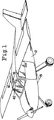
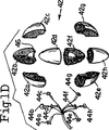
より小さい自家用機12で主要に使用される、本発明の新規なUNICORNTMシステム10は、例えばポリスチレン又はルサイトなどの誘電材料から構成された中空出し球形アンテナ14(図1A)を備える。アンテナ14は、直径にして約0.3m(12インチ)であり、航空機のコックピットの上方にある航空機の上隆起部の位置18に固定された、保護的流線形状のユニコーン形透明レーダードーム16内に取り付けられる。ドーム16は、アンテナ14の作動に干渉しない材料から構成される。
【0011】
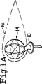
図1Bの破断図に示されたように、アンテナ14は、複数の等しいオレンジウェッジ(orange-wedge)のセクター、例えば8つの等しいオクタント14a、14b、14c、14d、14e、14f、14g及び14hへと、中空出し球形アンテナを削り出すことによって形成される。各々のオクタントは、これらのオクタントが、図1Aに示されるように一緒に固定されるとき、中央のキャビティが、信号送受信構成要素アセンブリ22をその内部に包含して形成されるように、えぐり出された内側エッジ20を有する。図3に関して詳細に説明されるように、アセンブリ22は、8つの送受信(T/R)ダイオードスイッチ24を備え、これらのスイッチにL−バンドのマイクロ波信号が供給され、該T/Rスイッチは、送信モードにおいて、8つのセクター即ちオクタントホーン全てを位相的に同時に駆動し、アンテナ14の回りの全方位に亘って8つのマイクロ波信号を送信するように作動する。
【0012】
アセンブリ22は、8つの低パワー、低ノイズのL−バンドのマイクロ波から可視光までの検出ダイオード26も備えており、各オクタントに連係された一つのダイオードは、T/Rスイッチ24が受信モードにあるとき近傍の航空機から反射して戻ってきた戻り信号を受信するために設けられる。
【0013】
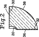
各オクタントでは、平坦表面30、32及び34は、金属スパッタリング又は蒸着プロセスにより塗布される例えば銀又は銅などの導電金属コーティング36で被覆されている。各オクタントの外側湾曲表面38は、被覆されない状態のままにされ、誘電電磁放射及び受信面として機能する。各オクタントの被覆表面30、32及び34は、その連係する検出ダイオード26に直ちに隣接して配置されたエッジ即ちコーナー40の内側に、外側表面38により受信された反射波を案内し即ち送り込む。
【0014】
球形アンテナ14は、各オクタントの被覆表面30、32及び34にセメント又は接着剤を塗布することによって組み立てられ、中央中空キャビティ内の構成アセンブリ22と共にオクタントを押す。セメントは、コーティング36即ちアセンブリ22の構成要素に損傷を与えない溶媒により解かすことができる型式であるべきである。かくして、アンテナに修復をなすことができ、不調アンテナを廃棄する必要がなくなる。
【0015】
アンテナ14は、セクター14dが左舷上方/前方方向に、セクター14aが右舷の上方/前方、セクター14cが左舷/上方/後方に、セクター14bが左舷/下方/前方に、セクター14eが右舷/下方/前方に、セクター14gが左舷/下方/後方に、セグメント14fが右舷/下方/後方に、各々面するように、航空機12に取り付けることができる。このようにして、アンテナ14は、航空機回りの包括的な全方位をカバーする。
【0016】
同軸パワーケーブル43が、アンテナ14から外側に延在しており、アセンブリ22を、図3の回路を介して、パイロットの目線レベルの前方且つ僅か上方に、コックピット内に直接取り付けられた視角インジケータディスプレイユニット42に接続する。かくして、パイロットは、彼の通常の前方視野を妨害されることなく、ユニット42を容易に見ることができる。
【0017】
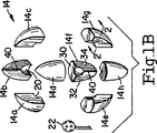
ディスプレイユニット42は、アンテナ14のセクター14a〜14hに各々対応する8つのオレンジ−ウェッジセクター42a〜42hに切削された透明中空球形部分である。8つの異なる色の表示ライト44a〜44hのクラスターは、球内部に取り付けられ、この状態で、各ライト44a〜44hが、その夫々対応するセクター42a〜42hに隣接して配置されている。セクター42a〜42hは、例えば該セクターの平坦表面上に取り付けられた透明ベルクロコネクター46によって、一緒に取り外し可能に固定され、それにより、必要時に、ライトを迅速且つ容易に変更することができる。ディスプレイユニット42は、パイロットが照明されたセクター42a〜42hを観察したとき、迅速に近傍の航空機の位置を知ることができるように、セクター42a〜42hの各々が配置され、且つ、その対応するセクター14a〜14hと整列される態様で、コックピット内に取り付けられている。例えば、セクター42aは、右舷/上方/前方位置を示し、或いは、セクター42eは、左舷/下方/後方を示す。パイロットは、迅速に必要となる回避処置を取ることができる。
【0018】
航空機12に取り付けられた本発明のUNICORNTMシステム10は、シングアラウンド(sing-around)フィードバッグ52内の中心エレメントである、デジタルクロック、カウンター/シンセサイザー50によって制御される。その静止モードでは、クロック50は、航空機12の回りの安全な大気の所望半径と一致する最小パルス繰り返し範囲(PRF)でパルスモジュレータ54に、タイミングパルスを供給する。次に、モジュレータ54からのパルスは、FCCにより許されるある一定のL−バンドマイクロ波周波数の一つに調整されるパワー増幅器/発信器56に供給される。パワー増幅器/発信器56は、ガンダイオード(Gunn-diode)型式又はインパットダイオード(Impatt diode type)型式であってもよい。ガンダイオード型式が使用されるとき、航空機回りの安全な球半径は、約3.7km(2海里)である。より高価でより高度な究極のインパットダイオードのパワー増幅発信器を使用した場合、安全球半径は、約9.3km(約5海里)にまで拡大され、明らかに、当該安全球内にある、例えば航空機TAなどの他の脅威となる航空機との衝突に対して、パイロット即ち航空機12への早期警告時間を改善する。
【0019】
パワー増幅器/発信器は、8つの送信/受信(T/R)スイッチ24のクラスターを供給し、これらのスイッチの各々は、誘電球形アンテナ14の8つのセクター14a〜14hの一つに結合される。送信モードにあるとき、スイッチ24は、8つのセクター14a〜14hの全てを位相的に同時に駆動するように作動し、これによって、8つのマイクロ波レーダービームを、アンテナ14及び航空機12の回りの全方位に送信する。
【0020】
スイッチ24が受信モードにあるとき、脅威となる航空機TA、前方地形60、或いは、地面Gから反射され、及び、セクター14a〜14hの対応する一つの誘電表面30に戻ってそこを通過する波は、当該セクターと連係された8つのL−バンドマイクロ波ダイオード検出器26のクラスターの一つにより検出される。上述したように、平坦表面30、32及び34上の導電コーティング36は、検出器26へ反射戻り波を案内し、即ち送り込み、これによって、システムの検出容量を強化するアパーチャゲインを提供する。
【0021】
戻ってきたL−バンドのレーダーエコーは、当該セグメントの受信機ビームパターンの最大応答軸(MRA)に近接した受信機セクター14a〜14hの一つに到達する戻りエネルギーを提供する。L−バンド付近の周波数、例えば約1ギガヘルツでは、マイクロ波放射は、約3×10⁸m/s/109Hz=0.3m=30cm=1フィートのおおよその波長を持っている。誘電波ガイドアンテナ14の大量の電磁波(em)は、自由空間のものに選択された誘電率の平方根の逆数の比率によって、3×108m/s(自由空間の光速度)以下に減少された位相波速度で移動する。かくして、誘電球14は、0.3m(1フィート)より僅かに小さい直径を持ち得る。
【0022】
検出ダイオード26の各々は、航空機衝突ピークセレクター及びチャンネルインジケータ64に、一定方向のパルス化整流信号62を提供する。これらのダイオード26は、信号62を生成するため、受動ビデオ合致フィルター(passive video matched filter)、即ち、ビデオ合致されたフィルター処理の活性形態を達成するように抵抗/コンデンサフィードバッグ回路を備えたトランジスタービデオ増幅器を備える。
【0023】
各セクター14a〜14hからの8つのビデオ増幅/ビデオフィルター処理信号62、並びに、その連係する検出器26は、セレクター64によって、8つのダイオードチャンネルピーク選択プロセスを受ける。このセレクターは、8つの信号62のうち最大のものを選択し、当該信号のみが出力信号66としてチャンネルインジケータゲート68へと通過する。その受信ビームパターンMRAがエコー到着方向により近いセクターが、セレクター64内のチャンネル表示ロジックを通して選択される一つとなる。出力信号66は、セクター14a〜14hのうちどの一つがピーク信号を受信するかを表示し、かくして、脅威となる航空機TA又は他の障害物の位置に対応する、当該ピーク信号が受信される方向を指し示す。高い目標選択として、セレクター64は、方位角及び仰角の精度を向上させるため、左舷−右舷及び上−下の受信機−ビームチャンネルの間の対態様の相違化によって、受信ビームの改変を容易にするため、例えばバッグバイアス(back-biased)されたツェナーソリッドステートダイオードを使用した対数増幅器を各々備えてもよい。
【0024】
チャンネルインジケータゲート60は、信号70を、可聴警報及びライトフリッカー/ライト生成器72に通過させる。可聴警報及びライトフリッカー/ライト生成器72は、可聴警報信号74を拡声器ホーン76に、及び、ライト生成信号78を透明ディスプレイ球42に送る。拡声器ホーン及び透明ディスプレイ球は、両方ともコックピット内に取り付けられている。信号78は、脅威となっている航空機TAの位置即ち方向、脅威の航空機の範囲及び航空機の接近率に関する情報を持っている。その結果、ライト44a〜44hの一つ及びそれと連係する透明セクター42a〜44hの一つは、一つの受信機区分14a〜14h及びそのピーク戻り信号を検出したその検出器26に対応し、ライトアップ、明滅して、パイロットに当該情報を提供する。同様に、エイシングアラウンド(Asing-around)作用の故に、発信音及びホーン76の発信率は、脅威となる航空機TAの距離又は範囲並びに接近率に関する情報を提供する。十分に早い警報時間を提供するこの情報を用いた場合、航空機12のパイロットは、彼の飛行機を巧みに操作して航空機TAとの衝突を回避することができる。
【0025】
ピーク信号80が、セレクター/インジケータ64から航空機衝突スレッショールド装置82に送られ、SNRで決定された検出確率に応じた安全範囲球への接触スパンに従って、許容可能なフォールス警報(false alarm)/接触率(contact rate)を確立する。
【0026】
フォールス接触率(例えば、クラッター又は他のエコー)は、その夫々のスレッショールドを超えたビデオ信号が、早い及び遅いゲート範囲の間にまたがっているときを示すスプリットレンジゲート(split range gate)84の使用によって更に減少される。これは、その面積が短期間の積分を通して得られ、且つ、早期対遅い範囲のゲートに落ちる、ビデオパルスXの部分の面積を差別化することによって表示される。相違の表示がゼロを通過するとき、ビデオパルスの中心が配置される。ロジック86は、第1の接触が通常通り選択されることを確保するため設けられる。
【0027】
セレクター及びチャンネルインジケータ64は、地面接近警報を容易にするためプラグインモジュール90を、前方地形衝突及び角度方向回避インジケータを容易にするためプラグインモジュール92を提供することによって更新することができる。モジュール90は、ピークとして選択された信号を導出するため、セクター14e(右舷/下方/前方)及び14h(左舷/下方/前方)から情報を受け取る。ユニット64からのピーク出力信号80に関して、モジュール90からのピーク出力信号94は、スレッショールド回路96及びスプリットレンジゲート回路98に委ねられ、次に、ロジック回路86に送られる。同様にして、モジュール100からのピーク出力信号100は、スレッショールド回路102及びスプリットレンジゲート回路104に委ねられ、次に、ロジック回路86に送られる。
【0028】
セクター14a〜14hの一つが脅威の航空機TAを検出し、セレクター64がスレッショールド装置82及びレンジゲート84を通して処理される信号80を最終的に提供し、次にロジック回路86に送られるとき、その第1の脅威の接触は、該回路によって選択され、対応する優先出力信号106がシングアラウンドフィードバッグループ52により捕捉される。信号106は、通常の着陸滑空スロープ下降率の情況の間に、地面接近警報が鳴らず、表示されないことを確実にするシングアラウンド率(sing-around rate)カウンタースレッショールド回路108に送られる。信号110は、次のシングアラウンドフィードバッグループサイクルを作動させるため回路108からクロック50に送られる。
【0029】
モジュール90及び92からの信号94及び100の各々は、出力信号106が最高の優先的脅威を代表するように、ロジック86内のオーバーライド決定回路を経由して第1の脅威となる接触信号80を無効にしてもよい。例えば、地面エコーがセクター14e〜14hの4チャンネルのうち一つのチャンネルに到達した場合、ロジック86により選択されたピーク信号は、出力信号100から導き出される。
【0030】
ロジック86からの別の出力信号112は、チャンネルインジケータゲート68及び遅延されたシュミットトリガー113の両方に供給される。ゲート68に供給されるような信号112は、選択されたチャンネルに関する情報を乗せているだけではなく、選択された接触オプショングループ内のチャンネルに関する情報、例えば、モジュール92により検出されるような前方地形衝突警報又はモジュール90により検出されるような地面接近警報に関係する情報を乗せている。この情報は、様々に異なって同定する、ホーン76における可聴警報及び表示球42上のライト明滅/色ライト信号を選択的に生成するように生成器72を作動させるためチャンネルインジケータゲート68を条件付ける。これらの警報信号から、航空機12のパイロットは、衝突を回避するため迅速に巧みな処置を取ることができる。
【0031】
遅延されたシュミットトリガー114は、スレッショールドビデオ信号112をカウンター108に供給されたデジタルトリガー出力116に転換する。トリガー114により生じられた遅延は、回路の詳細設計の設定時間を、戻ってきた脅威信号が受信された後で、次のシングアラウンドフィードバッグループサイクルが作動される前に設定することを可能にする。
【0032】
シングアラウンド率の制御/スレッショールド108は、既に説明された。放射範囲の情報がシングアラウンドフィードバッグループサイクルの間の時間内に内在されるのとは別に、これらのサイクルのPRFの変化は、相対的な放射範囲の接近率上に情報を乗せることに着目されたい。この後者の量は、衝突の切迫を評価する際の重要な測度である。しかし、幾つかの低い接近率状況の下では(例えば、通常の滑空スロープ着陸の間の地面に接近するときの下降率)、可聴警報又は視角警告表示は、逸らされ得る。勿論、手動のオーバーライドを適用することができるが、パイロットに部分的な予測を必要とする。カウンター108の目的は、シングアラウンドフィードバッグループ52を、好都合な情況の間に時期尚早にトリガーされることから下検分するため、半径範囲の接近率情報へのスレッショールド機能を適用することである。次に、トリガー機能は、ロジック86が脅威となる可能性のある事象とみなすことが合理的であると指令したときのみ有効とされる。そうでなければ、コントローラは、シングアラウンドフィードバッグループを、その静止状態に戻す。
【0033】
チャンネルインジケータゲート58は、既に説明された。モジュール90及び92無しの基本となるUNICORNTMシステムの場合には、その唯一の機能は、回路82及び84を通して有効とされるように、信号80のチャンネル表示を取ることである。このとき、半径範囲、半径範囲の接近率及びオクタントセクター接触情報を迅速であるがパイロットに識別可能且つ一義的に伝達することを如何に実行すべきかを可聴警報及びライト明滅色ライトで指令するための手段としてロジック86により第1の接触選択(contact selection)が実行される。
【0034】
可聴警報及びライト明滅/色ライト生成器は、簡潔な情報と共に迅速、一義的で明瞭な表示をパイロットに提供して衝突情況を防止するため、可聴警報として拡声器ホーン76、及び、オクタントのヘッヅアップ(heads-up)ディスプレイ42を駆動する信号を生成するため使用される。この簡潔な情報は、迅速で自主的な衝突回避操作を可能にし、即ち、十分早期な警報を可能にし、衝突を回避するだけではなく、ニアミスを減少することをも容易にする。
【0035】
拡声器76は、様々な可聴警報トーンのシーケンスを再生成するため使用される。その音の内容は、即ち、急速に反応する必要に関して緊急の意味合いを伝達する、ビー―――ビー―――ビー――ビー−ビー−ビーという、これら発信音シーケンスのPRFを変化させることにより、半径範囲及び半径範囲接近率を伝達する一方で衝突又はニアミスが差し迫ってくるタイプを同定する。
【0036】
透明ディスプレイ球42では、異なる色に符号化されたライトが、8つの危機的コライダー(corridor)、即ち、左舷/上方/前方、左舷/上方/後方、左舷/下方/前方、左舷/下方/後方、右舷/下方/前方、右舷/下方/後方、右舷/下方/前方、及び、右舷/下方/後方を同定する。更には、異なる色の符号化は、地面接近警報、前方地形衝突警報及び回避表示を示すため使用される。(可聴警報に類似した)色識別ライトの光明滅は、差し迫る衝突又はニアミスに応答する際の緊急度を伝達するために使用される。
【0037】
頭上空間が制限される非常に小さいコックピットでは、球形ディスプレイユニット42を、インストルメントパネルに取り付けられた一対の前方及び後方平坦スクリーンディスプレイに代替することが望ましい。
【0038】
前述したように、UNICORNTMシステムを、より小さい航空機に対するTCASの要求と両立させることが希求されている。このより小さい航空機は、航空機の型式、GPS位置(利用可能である場合)及び衝突の可能性を迅速に判断する際に役立つ他の情報で符号化された応答信号を用いてTCASを設置した航空機から放射された質問に応答する上で強力なレーダー断面(RCS)が欠けている。この応答モードのため必要とされる複合化及び符号化機能は、エレメント64、50及び54内に収容された、適切なGPS受信機の能力の設置と共に更新されたオプションとして容易に適合することができる。TCASに対してUNICORNTMシステム(特にガンダイオードのオプションの下で)と連係されたより低いマイクロ波パワーレベルでは遥かに劣勢となる、相互の干渉に関する懸念事項と取り組む際には、ホイスパー(whisper)及びシャウト(shout)モードを、更なる更新オプションとして用いることができる。これは、一旦、警告サイクルが開始された場合、フルパワーで用いられるよりも静止モードの間により低いパワーを放射するようにPA/OSCモジュール56をパルス出力する工程を含む。
【0039】
UNICORNTMシステムがTCASにより取り組まれた問題に直面しないことに言及することは価値がある。TCASの設計では、大きい民間のエアーライナーがより小さい航空機と衝突し即ちその上に下降するという設計上の問題を持っている。これらのより小さい航空機は、遥かに小さいRCSを持ち、概して、エアーライナーの大気中速度の性能を持っていないが、それにも拘わらず、極度の回避処理をより良く取ることができる。より小さいRCSは、パルス応答機により提供されるようなレーダーエコー戻り強化機能を必要とする。これは、勿論、例えばGPS受信機などの他の有用な情報及び他のデータを、より小さい航空機による符号化応答機の戻り信号に追加することを可能にする。これとは反対に、UNICORNTMシステムは、より小さい航空機への応用を描いており、脅威となる可能性のある航空機の一つとしてより大きいRCSを持つエアーライナーを、想定している。他のより低いRCSの小さい航空機(それらの低い大気中速度のため)は、急速には接近せず、これによって、減少された早期警報時間と比較して、対応する迅速さの減少した接近に起因して、より小さいRCSと連係されるより短いレンジをより許容可能にする。
【0040】
乗員及びキャビンの乗務員の安全性に留意した場合、民間のエアーライナーは、それが大惨事が切迫していることが明らかとなるまで、より小さい航空機との衝突を避けるために激しい回避操作を取ろうとはしない傾向にある。これとは反対に、UNICORNTMシステムが設けられた、より小さい航空機、一般航空機又は会社の航空機は、破局を回避するのに十分な時間で自主的な制御を取ることができる。
【0041】
上述したように、8つのセクター14a〜14hは、航空機12の頂部に取り付けられた球形アンテナ14を形成するため一緒に接着されている。例えばパイパーキューブ(Piper cub)などの高く飛行する航空機の中には、航空機の構造によるEMの遮蔽が考慮され得る。そのような場合には、アンテナ40は、各々がそれ自身の保護ドーム16内に閉じ込められた分離した上側及び下側の半球として形成されてもよい。上側半球は、コックピットの上方且つ僅かに背後のその通常の位置に取り付けられ、その一方で、下側半球は、上側半球とは径方向反対側の例えば図1の15の破線で示されるように飛行機の下方に取り付けられる。両方の半球は、ディスプレイユニット42に同軸ケーブルを介して適切に接続される。更には、完全な球形アンテナが航空力学的な引きずりを形成するような非常に小さい航空機では、アンテナは2以上に、8程度の立体角(solid-angle)セクターへと分割されてもよく、これらのセクターが航空機の断面の回りに均一に分布する態様で航空機被覆に埋め込まれることを可能にする。これは、航空力学的な引きずりを最小にする。
【0042】
UNICORNTMシステムは、大きな海洋船との衝突を回避する娯楽のボート乗員により使用するための安かな海洋衝突警報装置としての役割をも満足させる。この用途では、誘電アンテナの上側半球のみが必要とされる。更には、全方位の送信は、構造上、直接のEM波と干渉する海洋表面からの反射EM波による補強の故に、L−バンドのマイクロ波送信機の半球カバーを補強するように偏光される。米国コーストガード(U.S.Coast Guard)は、自動同定システム(AIS)技術の大規模なテストを実施している。AISは、TCASと非常に類似している。その一方で、応答機による返答の部分としてGPS情報を必要としている。重要なことには、UNICORNTMシステムは、その作動の自主的モードを有することに加えて、AISに適合するのみならず、4つの象限角度能力(上側半球において)のため、カルマンフィルターの回帰/予測処理が、衝突進路が差し迫っているか否かをより正確に決定することを可能にする能力を有意に改善する。再び、ホイスパー及びシャウト作動は、他の多数の娯楽船及び大型船との相互のL−バンドEM干渉を最小にするため用いることができる。
【0043】
飛行中衝突回避UNICORNTMシステムに関して、様々な更新オプションを、娯楽ボート乗員が彼らの船に投資した金額に従って、提供することができる。GPS受信機に投資した娯楽船オペレータのため、米国コーストガードは、彼らが、満足のいくかも知れないAIS応答機に投資することを希望している。しかし、一般的なUNICORNTMシステムは、比較的安価な娯楽ボートの所有者にとってより良い投資となることが理解できよう。その上、AISとのその適合性は、そのような所有者が、後日にGPS受信機及び適切なUNICORNTMシステムAIS更新モジュールを追加することによって更新することを促進させる。
【0044】
UNICORNTMシステムの別の輸送省(Department of Transportation; DOT)の用途は、直接前方に質問し、及び、鉄道トラックの湾曲部分上を移動するとき正面に向いたままにするため2又は3の隣接ビームを受信するように適合された前方地形衝突警報能力と同一種類の何らかの機能を含むことができる。これは、先頭列車両へと押し分けて進む従動列車両の後端部衝突を防止するように機能する。これとは反対に、列車の後部に取り付けられた類似のUNICORNTMシステムの適合性は、列車のエンジニアにそれとは反対の情況を避けるように、速度アップすることを指令することができる。再び、AISの能力は、そのようなUNICORNTMシステムの適合性へと統合することができる。
【0045】
本発明は、その精神即ち本質的特徴から逸脱することなく、他の特定の形態で実施することができる。そのため、本実施形態は、あらゆる点で図示としてみなされるべきであり、これに限定されるものではない。本発明の範囲は、前述した説明によってではなく請求の範囲により示され、該請求の範囲と均等の意味及び範囲内にある全ての変更が、その中に包含されるべきである。例えば、請求の範囲では、球形という用語の使用は、球形アンテナ14、及び、半球又は上述した他の立体角のセクターへの適合を覆うことが意図されている。
【図面の簡単な説明】
【図1】 図1は、航空機の頂上部に取り付けられた新規な誘電アンテナ、及び、。パイロットの容易な視角内で航空機のコックピットに即ち該コックピット内に取り付けられた、これに対応する透明ディスプレイユニットを示す本発明のUNICORNTMシステムの概略的な斜視図である。
図1Aは、球形アンテナを拡大図で示したものである。
図1Bは、球形アンテナを破断図で示したものである。
図1Cは、透明ディスプレイユニットを拡大図で示したものである。
図1Dは、透明ディスプレイユニットを破断図で示したものである。
【図2】 図2は、アンテナのセクターの各々における被覆表面を示す、図1Bのライン2−2に沿って取られた図である。
【図3】 図3は、本発明のUNICORNTMシステムに組み込まれた検出及び制御の概略的電子回路を示す。[0001]
BACKGROUND OF THE INVENTION
The present invention relates generally to collision avoidance systems for aircraft, and more particularly to affordable, new, low cost, comprehensive collision prevention and near miss reduction systems that are particularly useful in small private aircraft.
[0002]
[Prior art]
In crowded aircraft traffic areas and / or poor visibility conditions, one aircraft pilot warns of the presence of nearby aircraft so that he can maneuver the aircraft to avoid catastrophic collisions. Need to be done. A system known as TCAS (traffic warning and collision avoidance system) utilizes an interrogator installed on a commercial jet aircraft and a responder on each aircraft that it is likely to encounter. In this way, questions are sent and received by the radar between the aircraft carrying the TCAS and the smaller, threatening aircraft in the vicinity. This is done so that the amplified radar signal is sent back to the jet aircraft to allow civilian pilots to avoid collisions. The transponder encodes the returned radar signal with information unique to the threating aircraft on which it is installed. The GPS receiver is re-commanded to encode information about the location of the threat aircraft relative to the location of the jet aircraft. When TCAS is used, a civil jet pilot is burdened to avoid a collision when a warning signal is received.
[0003]
However, these systems are very complex and very costly and are primarily used on civil sized aircraft. Due to the high cost, these systems are rarely seen on smaller privately owned aircraft, where pilots often fly blindly under conditions of bad weather and traffic conditions, often leading to inevitable collisions. Only installed. General aircraft industry pilots are also reluctant to incur the cost of installing a transponder and do not avoid collisions and gain autonomous control.
[0004]
[Problems to be solved by the invention]
Thus, there is a need for a low cost, reliable warning and collision avoidance system that is particularly useful for small private aircraft to enhance flight safety conditions within the aircraft traffic industry. UNICORN described below TM The system meets that need.
[0005]
[Means for Solving the Problems]
Accordingly, it is a primary object of the present invention to provide a low cost, high reliability, comprehensive omnidirectional detection system. This detection system provides an early warning to an aircraft pilot of the presence of another aircraft in the vicinity of the air surrounding the aircraft, thus preventing the pilot from colliding with other nearby aircraft. It can be attached to the aircraft to make it possible to take any maneuvering action required.
[0006]
Another object of the present invention is that it operates independently from a single aircraft and does not require a response from other nearby aircraft, i.e. it is equipped with a system adapted to the other aircraft. It is to provide a system identified above that does not need to be present.
[0007]
Yet another object of the present invention was cut into multiple orange wedge sectors, for example, eight sectors covering eight different transmitter / receiver direction patterns (up / down, port / starboard, front / back). An object of the present invention is to provide the above-described detection system including an omnidirectional L-band microwave antenna formed by a dielectric sphere. L-band microwave signals are transmitted simultaneously from all eight dielectric sections to provide omnidirectional transmission covering the detection sphere around the aircraft. In addition, the same eight dielectric sectors are used with appropriate receiver circuitry to receive back-reflected microwave signals from other nearby aircraft. These sectors provide eight video channels, which allow aircraft pilots to perform appropriate avoidance operations to avoid catastrophes, as well as the direction, proximity and proximity of nearby aircraft. Approach rate Receive information about (rate of closure).
[0008]
A further object of the present invention is that it is self-supporting within itself and does not require a response mechanism that cooperates with nearby aircraft, but is compatible with and used with a TCAS type responder. Can be in the system described above.
[0009]
Other objects and advantages of the present invention will become apparent upon reading the following detailed description of the invention with reference to the accompanying drawings.
[0010]
DETAILED DESCRIPTION OF THE INVENTION
New UNICORN of the present invention, primarily used in smaller private aircraft 12 TM The
[0011]
As shown in the cutaway view of FIG. 1B, the
[0012]
The
[0013]
In each octant, the
[0014]
The
[0015]
The
[0016]
A viewing angle indicator display in which a
[0017]
The
[0018]
UNICORN of the present invention mounted on aircraft 12 TM The
[0019]
The power amplifier / oscillator provides a cluster of eight transmit / receive (T / R) switches 24, each of which is coupled to one of the eight
[0020]
When the switch 24 is in receive mode, the waves reflected from the threating aircraft TA, forward terrain 60, or ground G, and returning to and passing through one corresponding
[0021]
The returned L-band radar echo provides the return energy to reach one of the
[0022]
Each of the detection diodes 26 provides a unidirectional pulsed rectified signal 62 to the aircraft crash peak selector and channel indicator 64. These diodes 26 are transistors with a resistor / capacitor feedback circuit to achieve a passive video matched filter, ie, an active form of video matched filtering, to generate the signal 62. A video amplifier is provided.
[0023]
The eight video amplification / video filtering signals 62 from each
[0024]
Channel indicator gate 60 passes signal 70 to audible alarm and light flicker /
[0025]
A peak signal 80 is sent from the selector / indicator 64 to the aircraft collision threshold device 82, and according to the contact span to the safety range sphere according to the detection probability determined by the SNR, an acceptable false alarm / Establish a contact rate.
[0026]
The false contact rate (eg, clutter or other echo) is a split range gate 84 that indicates when video signals that exceed their respective thresholds straddle between the early and late gate ranges. Is further reduced by the use of. This is indicated by differentiating the area of the portion of the video pulse X whose area is obtained through short-term integration and falls to the early vs late range gate. When the difference indication passes through zero, the center of the video pulse is placed. Logic 86 is provided to ensure that the first contact is selected as usual.
[0027]
The selector and channel indicator 64 can be updated by providing a plug-in module 90 to facilitate ground approach alerts and a plug-in
[0028]
When one of the
[0029]
Each of the
[0030]
Another output signal 112 from logic 86 is provided to both channel indicator gate 68 and delayed Schmitt trigger 113. The signal 112 as supplied to the gate 68 not only carries information about the selected channel, but also information about the channel within the selected touch option group, eg, the front terrain as detected by the
[0031]
The delayed Schmitt trigger 114 converts the threshold video signal 112 into a digital trigger output 116 that is fed to the
[0032]
Sing-around rate control /
[0033]
The channel indicator gate 58 has already been described. Basic UNICORN without
[0034]
Audible alert and light flicker / color light generators provide loudspeaker horn 76 and octant heads up as audible alerts to provide a quick, unambiguous and clear indication to pilots with concise information to prevent collision situations (Heads-up) Used to generate signals that drive the
[0035]
Loudspeaker 76 is used to regenerate various audible alarm tone sequences. By changing the PRF of these dial tone sequences, bee--bee--bee-bee-bee-bee, which conveys urgent implications regarding the need to respond quickly, ie , Radius range and radius range Approach rate Identifies the type of collision or near miss that is imminent.
[0036]
In the
[0037]
In very small cockpits where overhead is limited, it is desirable to replace the
[0038]
As mentioned above, UNICORN TM There is a need to make the system compatible with TCAS requirements for smaller aircraft. This smaller aircraft is an aircraft that has installed TCAS with a response signal encoded with the aircraft type, GPS location (if available) and other information useful in quickly determining the likelihood of a collision. It lacks a powerful radar cross section (RCS) in responding to questions radiated from. The decoding and encoding functions required for this response mode can easily be adapted as an updated option with the installation of appropriate GPS receiver capabilities housed in
[0039]
UNICORN TM It is worth mentioning that the system does not face the problems addressed by TCAS. The TCAS design has the design problem of a large civilian airliner colliding with, or descending on, a smaller aircraft. These smaller aircraft have a much smaller RCS and generally do not have the airliner's atmospheric speed performance, but can nevertheless take better extreme avoidance. A smaller RCS requires radar echo return enhancement as provided by a pulse transponder. This, of course, makes it possible to add other useful information and other data, such as a GPS receiver, to the return signal of the smaller aircraft's encoded transponder. On the other hand, UNICORN TM The system depicts applications for smaller aircraft and envisions an airliner with a larger RCS as one of the potential threat aircraft. Other lower RCS small aircraft (due to their low atmospheric speed) do not approach quickly, thereby reducing the corresponding agility compared to the reduced early warning time Approach Makes the shorter range associated with a smaller RCS more acceptable.
[0040]
When paying attention to the safety of passengers and cabin crew, the civil airliner takes heavy evasive maneuvers to avoid collisions with smaller aircraft until it becomes clear that a catastrophe is imminent. There is a tendency not to try. On the other hand, UNICORN TM Smaller aircraft, general aircraft, or company aircraft that are equipped with the system can take voluntary control in sufficient time to avoid catastrophe.
[0041]
As described above, the eight
[0042]
UNICORN TM The system also fulfills its role as an inexpensive marine collision warning device for use by recreational boat crews to avoid collisions with large marine ships. In this application, only the upper hemisphere of the dielectric antenna is required. Furthermore, the omnidirectional transmission is structurally polarized to reinforce the hemispherical cover of the L-band microwave transmitter due to reinforcement by reflected EM waves from the ocean surface that interferes with direct EM waves. . The US Coast Guard performs extensive testing of Automatic Identification System (AIS) technology. AIS is very similar to TCAS. On the other hand, GPS information is required as a response part by the responder. Importantly, UNICORN TM In addition to having a voluntary mode of operation, the system not only conforms to AIS, but also has four quadrant angular capabilities (in the upper hemisphere), so the Kalman filter's regression / prediction process is imminent on the collision path. Significantly improve the ability to determine more accurately whether or not Again, whisper and shout actuation can be used to minimize mutual L-band EM interference with many other pleasure and large ships.
[0043]
Collision avoidance UNICORN in flight TM With respect to the system, various update options can be provided according to the amount of recreational boat crew invested in their ships. For pleasure boat operators who have invested in GPS receivers, US Coast Guard wants to invest in an AIS transponder that they may be satisfied with. However, the general UNICORN TM It will be appreciated that the system is a better investment for owners of relatively inexpensive recreational boats. In addition, its compatibility with AIS is determined by such owners at a later date with GPS receivers and appropriate UNICORN. TM Promote updates by adding a system AIS update module.
[0044]
UNICORN TM Another Department of Transportation (DOT) application of the system is to query two or three adjacent beams in order to interrogate directly forward and remain facing forward when moving on a curved section of a railroad track. It may include some function of the same type as a forward terrain crash warning capability adapted to receive. This functions to prevent a rear end collision of a driven train vehicle that pushes forward to the leading train. On the other hand, a similar UNICORN attached to the rear of the train TM The suitability of the system can instruct the train engineer to speed up to avoid the opposite situation. Again, AIS capability is such a UNICORN TM Can be integrated into system suitability.
[0045]
The present invention may be embodied in other specific forms without departing from its spirit or essential characteristics. Therefore, this embodiment should be regarded as illustration in all points, and is not limited to this. The scope of the present invention is defined by the terms of the claims, not by the description above, and all modifications that come within the meaning and range of equivalency of the claims should be embraced therein. For example, in the claims, the use of the term spherical is intended to cover the adaptation to the
[Brief description of the drawings]
FIG. 1 shows a novel dielectric antenna attached to the top of an aircraft, and FIG. UNICORN of the present invention showing a corresponding transparent display unit mounted in or within the cockpit of an aircraft within the pilot's easy viewing angle TM 1 is a schematic perspective view of a system. FIG.
FIG. 1A is an enlarged view of a spherical antenna.
FIG. 1B shows a spherical antenna in a cutaway view.
FIG. 1C shows the transparent display unit in an enlarged view.
FIG. 1D shows the transparent display unit in a cutaway view.
FIG. 2 is a view taken along line 2-2 of FIG. 1B, showing the coated surface in each of the sectors of the antenna.
FIG. 3 shows the UNICORN of the present invention. TM Fig. 2 shows a schematic electronic circuit of detection and control integrated in the system.
Claims (14)
複数のセクターにより形成された球の少なくとも一部分として形成された誘電アンテナと、
L−バンドのマイクロ波送信機と、
複数の送受信スイッチであって、該スイッチの各々1つが前記セクターの各々1つと連係されている、前記送受信スイッチと、
前記スイッチが送信モードにあるとき、複数のL−バンドのマイクロ波信号が、前記アンテナの回りの全方位に前記セクターから同時に送信されるように、前記送信機を前記スイッチに接続する手段と、
複数のL−バンドのマイクロ波検出器であって、該検出器の各々1つは、前記スイッチが受信モードにあるとき、前記車両を取り囲む領域内の障害物から反射された戻りマイクロ波信号を検出するため、前記セクターの各々1つと連係される、前記マイクロ波検出器と、
前記障害物に関する情報を含む出力信号を提供するように戻りマイクロ波信号を処理するための回路手段と、
前記車両のオペレータが前記障害物との衝突を回避する上で適切な処置を取ることを可能とするように該車両のオペレータに当該情報を表示するため前記回路手段に接続された表示手段と、
を備える、衝突回避システム。 A collision avoidance system for use in a vehicle ,
A dielectric antenna formed as at least a portion of a sphere formed by a plurality of sectors ;
An L-band microwave transmitter;
A plurality of transmit / receive switches, each one of which is associated with each one of the sectors;
Means for connecting the transmitter to the switch such that when the switch is in transmit mode, a plurality of L-band microwave signals are simultaneously transmitted from the sector in all directions around the antenna;
A plurality of L-band microwave detectors, each one of which detects a return microwave signal reflected from an obstacle in an area surrounding the vehicle when the switch is in receive mode. The microwave detector associated with each one of the sectors for detection;
Circuit means for processing the return microwave signal to provide an output signal comprising information about the obstacle ;
Display means connected to the circuit means for displaying the information to the operator of the vehicle so as to allow the operator of the vehicle to take appropriate measures to avoid a collision with the obstacle;
A collision avoidance system .
複数の等しいサイズのウェッジセクターにより形成された球の少なくとも一部分として形成された中空の誘電アンテナであって、各セクターは外側球表面及び該球の中心に向かって径方向内側に延在する3つの平坦表面を有する、前記誘電アンテナと、
L−バンドのマイクロ波送信機と、
前記アンテナ内部に取り付けられた複数の送受信スイッチであって、該スイッチの各々1つが前記セクターの各々1つと連係されている、前記送受信スイッチと、
前記スイッチが送信モードにあるとき、複数のL−バンドのマイクロ波信号が、前記アンテナの回りの全方位に前記セクターから同時に送信されるように、前記送信機を前記スイッチに接続する手段と、
前記アンテナ内に取り付けられた複数のL−バンドのマイクロ波検出器であって、該検出器の各々1つは、前記スイッチが受信モードにあるとき、前記航空機を取り囲む領域内の障害物から反射され、且つ、その夫々のセクターにより受信される戻りマイクロ波信号を検出するため、前記セクターの各々1つと連係されており、前記セクターの平坦側部は、戻り信号をその連係する検出器にセクターを通して案内するため導電材料で被覆されている、前記マイクロ波検出器と、
前記障害物に関する情報を含む出力信号を提供するように戻りマイクロ波信号を処理するための回路手段と、
前記航空機のオペレータが前記障害物との衝突を回避する上で適切な処置を取ることを可能とするように該航空機のオペレータに当該情報を表示するため前記回路手段に接続された表示手段と、
を備える、衝突回避システム。 A collision avoidance system for use on an aircraft ,
A hollow dielectric antenna formed as at least a portion of a sphere formed by a plurality of equally sized wedge sectors, each sector comprising three outer sphere surfaces and radially inward toward the center of the sphere The dielectric antenna having a flat surface ;
An L-band microwave transmitter;
A plurality of transmit / receive switches mounted within the antenna, wherein each one of the switches is associated with each one of the sectors;
Means for connecting the transmitter to the switch such that when the switch is in transmit mode, a plurality of L-band microwave signals are simultaneously transmitted from the sector in all directions around the antenna;
A plurality of L-band microwave detectors mounted in the antenna, each one of which is reflected from obstacles in the area surrounding the aircraft when the switch is in receive mode. And is associated with each one of the sectors to detect a return microwave signal received by its respective sector, and the flat side of the sector transmits the return signal to its associated detector. Said microwave detector coated with a conductive material for guiding through;
Circuit means for processing the return microwave signal to provide an output signal comprising information about the obstacle ;
Display means connected to the circuit means for displaying the information to the aircraft operator so as to allow the aircraft operator to take appropriate action to avoid a collision with the obstacle;
A collision avoidance system .
Applications Claiming Priority (3)
| Application Number | Priority Date | Filing Date | Title |
|---|---|---|---|
| US09/255,269 | 1999-02-23 | ||
| US09/255,269 US6211808B1 (en) | 1999-02-23 | 1999-02-23 | Collision avoidance system for use in aircraft |
| PCT/US2000/004456 WO2000050920A1 (en) | 1999-02-23 | 2000-02-23 | Collision avoidance system for use in aircraft |
Publications (3)
| Publication Number | Publication Date |
|---|---|
| JP2002538437A JP2002538437A (en) | 2002-11-12 |
| JP2002538437A5 JP2002538437A5 (en) | 2008-05-29 |
| JP4124575B2 true JP4124575B2 (en) | 2008-07-23 |
Family
ID=22967584
Family Applications (1)
| Application Number | Title | Priority Date | Filing Date |
|---|---|---|---|
| JP2000601462A Expired - Fee Related JP4124575B2 (en) | 1999-02-23 | 2000-02-23 | Collision avoidance system for use on aircraft |
Country Status (7)
| Country | Link |
|---|---|
| US (2) | US6211808B1 (en) |
| EP (1) | EP1171782A4 (en) |
| JP (1) | JP4124575B2 (en) |
| AU (1) | AU758894B2 (en) |
| CA (1) | CA2362139C (en) |
| NZ (1) | NZ513457A (en) |
| WO (1) | WO2000050920A1 (en) |
Families Citing this family (48)
| Publication number | Priority date | Publication date | Assignee | Title |
|---|---|---|---|---|
| US7426437B2 (en) | 1997-10-22 | 2008-09-16 | Intelligent Technologies International, Inc. | Accident avoidance systems and methods |
| US7629899B2 (en) * | 1997-10-22 | 2009-12-08 | Intelligent Technologies International, Inc. | Vehicular communication arrangement and method |
| US8965677B2 (en) | 1998-10-22 | 2015-02-24 | Intelligent Technologies International, Inc. | Intra-vehicle information conveyance system and method |
| US7647180B2 (en) * | 1997-10-22 | 2010-01-12 | Intelligent Technologies International, Inc. | Vehicular intersection management techniques |
| US8255144B2 (en) * | 1997-10-22 | 2012-08-28 | Intelligent Technologies International, Inc. | Intra-vehicle information conveyance system and method |
| GB2360133B (en) * | 2000-03-11 | 2002-01-23 | Univ Sheffield | Multi-segmented dielectric resonator antenna |
| JP2004518213A (en) * | 2000-10-25 | 2004-06-17 | ユナイテッド パーセル サービス オブ アメリカ インコーポレイテッド | Altitude range filter for cockpit traffic display |
| GB0101567D0 (en) * | 2001-01-22 | 2001-03-07 | Antenova Ltd | Dielectric resonator antenna with mutually orrthogonal feeds |
| US6658775B1 (en) * | 2001-02-28 | 2003-12-09 | Anthony Lanzisero | Toll pass display assembly and system |
| US6669357B2 (en) | 2001-09-26 | 2003-12-30 | The Boeing Company | Surface illumination system of an aircraft and like vehicles |
| AUPR848601A0 (en) * | 2001-10-25 | 2001-11-15 | Poropat, George Vladimir | A collision warning system and method |
| FR2834070A1 (en) * | 2001-12-20 | 2003-06-27 | Thales Sa | Agricultural vegetation cutting/clearing machine radar height measurer having L band oscillator transmitting through vegetation towards ground and separate transmission collecting vegetation/ground height determining radar/ground distance |
| US7006032B2 (en) * | 2004-01-15 | 2006-02-28 | Honeywell International, Inc. | Integrated traffic surveillance apparatus |
| ATE414919T1 (en) * | 2004-09-07 | 2008-12-15 | William Michael Butler | COLLISION AVOIDANCE WARNING AND TAXI STEERING DEVICE |
| FR2875613B1 (en) * | 2004-09-23 | 2007-03-16 | Giat Ind Sa | HUMAN MACHINE INTERFACE OF A THREAT TREATMENT SYSTEM |
| US7307579B2 (en) * | 2004-11-03 | 2007-12-11 | Flight Safety Technologies, Inc. | Collision alerting and avoidance system |
| FR2878336B1 (en) * | 2004-11-19 | 2007-04-27 | Thales Sa | METHOD AND DEVICE FOR LOCATING AIRCRAFT, IN PARTICULAR FOR THEIR AUTOMATIC LANDING PHASE GUIDANCE |
| US20060224318A1 (en) * | 2005-03-30 | 2006-10-05 | Wilson Robert C Jr | Trajectory prediction |
| EP1731921A1 (en) * | 2005-06-01 | 2006-12-13 | Nederlandse Organisatie voor toegepast-natuurwetenschappelijk onderzoek TNO | Radar system for aircraft |
| US7457690B2 (en) * | 2005-12-14 | 2008-11-25 | Boeing Co | Systems and methods for representation of a flight vehicle in a controlled environment |
| WO2008045134A2 (en) * | 2006-03-07 | 2008-04-17 | Dimensional Research, Inc. | Airborne situational awareness system |
| US8380424B2 (en) | 2007-09-28 | 2013-02-19 | The Boeing Company | Vehicle-based automatic traffic conflict and collision avoidance |
| US8744738B2 (en) | 2007-09-28 | 2014-06-03 | The Boeing Company | Aircraft traffic separation system |
| US8060295B2 (en) * | 2007-11-12 | 2011-11-15 | The Boeing Company | Automated separation manager |
| US7986809B1 (en) * | 2008-08-19 | 2011-07-26 | United States Of America As Represented By The Secretary Of The Navy | Equation of linked multiple source measurements to a uniquely identified object |
| US8477063B2 (en) * | 2008-10-03 | 2013-07-02 | Honeywell International Inc. | System and method for obstacle detection and warning |
| US7898462B2 (en) * | 2008-10-03 | 2011-03-01 | Honeywell International Inc. | Multi-sector radar sensor |
| US7868817B2 (en) * | 2008-10-03 | 2011-01-11 | Honeywell International Inc. | Radar system for obstacle avoidance |
| US8538673B2 (en) * | 2008-10-31 | 2013-09-17 | Czech Technical University In Prague | System and method for planning/replanning collision free flight plans in real or accelerated time |
| US8570211B1 (en) * | 2009-01-22 | 2013-10-29 | Gregory Hubert Piesinger | Aircraft bird strike avoidance method and apparatus |
| US8264377B2 (en) | 2009-03-02 | 2012-09-11 | Griffith Gregory M | Aircraft collision avoidance system |
| DE102009019700A1 (en) * | 2009-05-05 | 2010-12-09 | Deutsches Zentrum für Luft- und Raumfahrt e.V. | Device for determining the position of vehicles |
| US8368584B2 (en) * | 2009-06-10 | 2013-02-05 | The University Of North Dakota | Airspace risk mitigation system |
| JP5639015B2 (en) * | 2011-07-06 | 2014-12-10 | 古野電気株式会社 | Antenna device, radar device, and dielectric member arrangement method |
| US8791836B2 (en) | 2012-03-07 | 2014-07-29 | Lockheed Martin Corporation | Reflexive response system for popup threat survival |
| US9030347B2 (en) | 2012-05-03 | 2015-05-12 | Lockheed Martin Corporation | Preemptive signature control for vehicle survivability planning |
| US8831793B2 (en) | 2012-05-03 | 2014-09-09 | Lockheed Martin Corporation | Evaluation tool for vehicle survivability planning |
| US9240001B2 (en) | 2012-05-03 | 2016-01-19 | Lockheed Martin Corporation | Systems and methods for vehicle survivability planning |
| US8976057B1 (en) * | 2012-07-02 | 2015-03-10 | Rockwell Collins, Inc. | TCAS primary antenna on aircraft underside system and method |
| KR101221978B1 (en) * | 2012-09-03 | 2013-01-15 | 한국항공우주연구원 | Localization method of multiple jammers based on tdoa method |
| US9832545B2 (en) * | 2013-10-11 | 2017-11-28 | Northrop Grumman Systems Corporation | System and method for providing a distributed directional aperture |
| US9645183B2 (en) * | 2014-08-20 | 2017-05-09 | At&T Intellectual Property I, L.P. | Methods, systems, and products for power management in cable assemblies |
| US10372122B2 (en) * | 2015-02-04 | 2019-08-06 | LogiCom & Wireless Ltd. | Flight management system for UAVs |
| US10822110B2 (en) | 2015-09-08 | 2020-11-03 | Lockheed Martin Corporation | Threat countermeasure assistance system |
| RU2646690C1 (en) * | 2016-10-10 | 2018-03-06 | Акционерное общество "Государственный Рязанский приборный завод" | Threshold device for signals of air traffic control systems |
| ES2729662T3 (en) | 2016-10-10 | 2019-11-05 | Deutsche Telekom Ag | Method for optimizing data transmission between a remotely controlled air vehicle and a telecommunications network, remotely controlled air vehicle, system, telecommunications network, program and computer program product |
| US10969484B2 (en) * | 2019-01-18 | 2021-04-06 | United Arab Emirates University | Bullet detection system |
| US11682313B2 (en) | 2021-03-17 | 2023-06-20 | Gregory M. Griffith | Sensor assembly for use in association with aircraft collision avoidance system and method of using the same |
Family Cites Families (21)
| Publication number | Priority date | Publication date | Assignee | Title |
|---|---|---|---|---|
| GB1140648A (en) * | 1967-09-26 | 1969-01-22 | Thomas Marschall Runge | Collision avoidance apparatus |
| US3620626A (en) | 1969-05-29 | 1971-11-16 | Quantronix Corp | Proximity warning system for aircraft |
| US3714651A (en) | 1970-08-14 | 1973-01-30 | Itt | Non cooperative collision avoidance system |
| CA1017835A (en) * | 1972-12-22 | 1977-09-20 | George B. Litchford | Collison avoidance/proximity warning system using secondary radar |
| US3961321A (en) * | 1973-09-17 | 1976-06-01 | Royston Arthur Leslie Moss | Omnidirectional ultrasonic intrusion surveillance unit |
| US3986182A (en) * | 1974-03-27 | 1976-10-12 | Sontrix, Inc. | Multi-zone intrusion detection system |
| FR2408842A1 (en) | 1977-11-10 | 1979-06-08 | Trt Telecom Radio Electr | AIRPORT OBSTACLE DETECTOR DEVICE |
| US4277170A (en) | 1979-11-01 | 1981-07-07 | Miles Richard B | Laser beacon and optical detector system for aircraft collision hazard determination |
| US4302734A (en) * | 1980-03-12 | 1981-11-24 | Nasa | Microwave switching power divider |
| DE3011238A1 (en) * | 1980-03-22 | 1981-10-01 | Licentia Patent-Verwaltungs-Gmbh, 6000 Frankfurt | MICROWAVE TRANSMITTER RECEIVER, ESPECIALLY FOR A DOPPLER RADAR SYSTEM |
| US4835537A (en) | 1986-07-16 | 1989-05-30 | Manion James H | Telemetry burst collision avoidance system |
| US4755818A (en) | 1986-08-15 | 1988-07-05 | The United States Of America As Represented By The Secretary Of The Army | Aircraft collision warning system |
| US4918442A (en) | 1988-10-03 | 1990-04-17 | Bogart Jr Donald W | Airplane collision avoidance system |
| US4951056A (en) | 1989-06-26 | 1990-08-21 | The United States Of America As Represented By The Secretary Of The Navy | Collision detection system |
| US5057833A (en) | 1989-11-07 | 1991-10-15 | Otl, Inc. | Passive optical air traffic alert system |
| US5111210A (en) * | 1990-06-22 | 1992-05-05 | Survival Safety Engineering, Inc. | Collision avoidance radar detector system |
| US5638281A (en) | 1991-01-31 | 1997-06-10 | Ail Systems, Inc. | Target prediction and collision warning system |
| FR2680751A1 (en) | 1991-09-03 | 1993-03-05 | Thomson Csf | COLLISION REMOVAL METHOD FOR COOPERATIVE CARRIERS AND ONBOARD OPTICAL ASSEMBLY FOR ITS IMPLEMENTATION. |
| FR2682791B1 (en) | 1991-10-18 | 1995-04-28 | Thomson Csf | METHOD OF AVOIDING COLLISIONS BETWEEN AIRCRAFT AND OPTICAL ASSEMBLY FOR ITS IMPLEMENTATION. |
| DE4243669A1 (en) | 1992-12-23 | 1994-06-30 | Deutsche Aerospace | Process for monitoring an area and arrangement for carrying out the process |
| DE4323511C1 (en) | 1993-07-14 | 1995-01-26 | Deutsche Aerospace | Radar device for obstacle warning |
-
1999
- 1999-02-23 US US09/255,269 patent/US6211808B1/en not_active Ceased
-
2000
- 2000-02-23 JP JP2000601462A patent/JP4124575B2/en not_active Expired - Fee Related
- 2000-02-23 AU AU34985/00A patent/AU758894B2/en not_active Ceased
- 2000-02-23 NZ NZ513457A patent/NZ513457A/en unknown
- 2000-02-23 CA CA002362139A patent/CA2362139C/en not_active Expired - Fee Related
- 2000-02-23 WO PCT/US2000/004456 patent/WO2000050920A1/en not_active Application Discontinuation
- 2000-02-23 EP EP00913560A patent/EP1171782A4/en not_active Withdrawn
-
2003
- 2003-02-10 US US10/360,744 patent/USRE39053E1/en not_active Expired - Fee Related
Also Published As
| Publication number | Publication date |
|---|---|
| EP1171782A4 (en) | 2004-05-06 |
| CA2362139A1 (en) | 2000-08-31 |
| NZ513457A (en) | 2003-03-28 |
| US6211808B1 (en) | 2001-04-03 |
| AU758894B2 (en) | 2003-04-03 |
| WO2000050920A1 (en) | 2000-08-31 |
| EP1171782A1 (en) | 2002-01-16 |
| CA2362139C (en) | 2005-02-22 |
| USRE39053E1 (en) | 2006-04-04 |
| AU3498500A (en) | 2000-09-14 |
| JP2002538437A (en) | 2002-11-12 |
Similar Documents
| Publication | Publication Date | Title |
|---|---|---|
| JP4124575B2 (en) | Collision avoidance system for use on aircraft | |
| EP1372127B1 (en) | TCAS cooperative mid-air collision avoidance system | |
| US5933099A (en) | Collision avoidance system | |
| EP2669704B1 (en) | Airport surface collision-avoidance system (ASCAS) | |
| US5351032A (en) | Power line detection system | |
| EP0200787B1 (en) | System for displaying warning zone or menacing aircraft in an apparatus for preventing collision on aircraft | |
| US6252525B1 (en) | Anti-collision system | |
| US9959774B2 (en) | Systems and methods for displaying obstacle-avoidance information during surface operations | |
| US7379014B1 (en) | Taxi obstacle detecting radar | |
| EP1185849B1 (en) | Method and electronic circuit for predicting intensity and location of a wake vortex | |
| US7411519B1 (en) | System and method for predicting and displaying wake vortex turbulence | |
| US6665631B2 (en) | System and method for measuring short distances | |
| JP2008518844A (en) | Collision warning avoidance system | |
| JPH08511867A (en) | Identification of airport ground vehicles | |
| JP3565783B2 (en) | Airport information automatic transmission device | |
| US5861846A (en) | Aviation pilot collision alert | |
| US4298875A (en) | Aircraft collision avoidance system | |
| EP3683780A1 (en) | Obstacle detection using camera mounted on protrusion of vehicle | |
| US3660846A (en) | Automatic collision warning system | |
| WO1990015343A1 (en) | A system for detection, localization and classification of target objects | |
| US8902101B1 (en) | System for and method of wind shear detection | |
| US20200020239A1 (en) | Characteristics of graphical icons for presentation of traffic information | |
| US20030182060A1 (en) | Device and system for preventing collision of aircraft | |
| US11594144B2 (en) | Collision awareness using cameras mounted on a vehicle | |
| WO1982002432A1 (en) | Aircraft collision avoidance system |
Legal Events
| Date | Code | Title | Description |
|---|---|---|---|
| A621 | Written request for application examination |
Free format text: JAPANESE INTERMEDIATE CODE: A621 Effective date: 20050623 |
|
| A977 | Report on retrieval |
Free format text: JAPANESE INTERMEDIATE CODE: A971007 Effective date: 20071005 |
|
| A131 | Notification of reasons for refusal |
Free format text: JAPANESE INTERMEDIATE CODE: A131 Effective date: 20071012 |
|
| A601 | Written request for extension of time |
Free format text: JAPANESE INTERMEDIATE CODE: A601 Effective date: 20080115 |
|
| A602 | Written permission of extension of time |
Free format text: JAPANESE INTERMEDIATE CODE: A602 Effective date: 20080122 |
|
| A601 | Written request for extension of time |
Free format text: JAPANESE INTERMEDIATE CODE: A601 Effective date: 20080212 |
|
| A602 | Written permission of extension of time |
Free format text: JAPANESE INTERMEDIATE CODE: A602 Effective date: 20080219 |
|
| A521 | Request for written amendment filed |
Free format text: JAPANESE INTERMEDIATE CODE: A523 Effective date: 20080312 |
|
| A524 | Written submission of copy of amendment under article 19 pct |
Free format text: JAPANESE INTERMEDIATE CODE: A524 Effective date: 20080312 |
|
| A521 | Request for written amendment filed |
Free format text: JAPANESE INTERMEDIATE CODE: A821 Effective date: 20080312 |
|
| TRDD | Decision of grant or rejection written | ||
| A01 | Written decision to grant a patent or to grant a registration (utility model) |
Free format text: JAPANESE INTERMEDIATE CODE: A01 Effective date: 20080428 |
|
| A01 | Written decision to grant a patent or to grant a registration (utility model) |
Free format text: JAPANESE INTERMEDIATE CODE: A01 |
|
| A61 | First payment of annual fees (during grant procedure) |
Free format text: JAPANESE INTERMEDIATE CODE: A61 Effective date: 20080502 |
|
| R150 | Certificate of patent or registration of utility model |
Free format text: JAPANESE INTERMEDIATE CODE: R150 |
|
| FPAY | Renewal fee payment (event date is renewal date of database) |
Free format text: PAYMENT UNTIL: 20110516 Year of fee payment: 3 |
|
| LAPS | Cancellation because of no payment of annual fees |