JP4112803B2 - Mobile communication system for billing calls - Google Patents
Mobile communication system for billing calls Download PDFInfo
- Publication number
- JP4112803B2 JP4112803B2 JP2000510293A JP2000510293A JP4112803B2 JP 4112803 B2 JP4112803 B2 JP 4112803B2 JP 2000510293 A JP2000510293 A JP 2000510293A JP 2000510293 A JP2000510293 A JP 2000510293A JP 4112803 B2 JP4112803 B2 JP 4112803B2
- Authority
- JP
- Japan
- Prior art keywords
- subscriber
- mobile
- call
- communication system
- mobile communication
- Prior art date
- Legal status (The legal status is an assumption and is not a legal conclusion. Google has not performed a legal analysis and makes no representation as to the accuracy of the status listed.)
- Expired - Lifetime
Links
Images


Classifications
-
- H—ELECTRICITY
- H04—ELECTRIC COMMUNICATION TECHNIQUE
- H04W—WIRELESS COMMUNICATION NETWORKS
- H04W4/00—Services specially adapted for wireless communication networks; Facilities therefor
- H04W4/24—Accounting or billing
-
- H—ELECTRICITY
- H04—ELECTRIC COMMUNICATION TECHNIQUE
- H04M—TELEPHONIC COMMUNICATION
- H04M15/00—Arrangements for metering, time-control or time indication ; Metering, charging or billing arrangements for voice wireline or wireless communications, e.g. VoIP
-
- H—ELECTRICITY
- H04—ELECTRIC COMMUNICATION TECHNIQUE
- H04M—TELEPHONIC COMMUNICATION
- H04M15/00—Arrangements for metering, time-control or time indication ; Metering, charging or billing arrangements for voice wireline or wireless communications, e.g. VoIP
- H04M15/70—Administration or customization aspects; Counter-checking correct charges
- H04M15/745—Customizing according to wishes of subscriber, e.g. friends or family
-
- H—ELECTRICITY
- H04—ELECTRIC COMMUNICATION TECHNIQUE
- H04M—TELEPHONIC COMMUNICATION
- H04M15/00—Arrangements for metering, time-control or time indication ; Metering, charging or billing arrangements for voice wireline or wireless communications, e.g. VoIP
- H04M15/80—Rating or billing plans; Tariff determination aspects
- H04M15/8083—Rating or billing plans; Tariff determination aspects involving reduced rates or discounts, e.g. time-of-day reductions or volume discounts
-
- H—ELECTRICITY
- H04—ELECTRIC COMMUNICATION TECHNIQUE
- H04M—TELEPHONIC COMMUNICATION
- H04M2215/00—Metering arrangements; Time controlling arrangements; Time indicating arrangements
- H04M2215/01—Details of billing arrangements
- H04M2215/0108—Customization according to wishes of subscriber, e.g. customer preferences, friends and family, selecting services or billing options, Personal Communication Systems [PCS]
-
- H—ELECTRICITY
- H04—ELECTRIC COMMUNICATION TECHNIQUE
- H04M—TELEPHONIC COMMUNICATION
- H04M2215/00—Metering arrangements; Time controlling arrangements; Time indicating arrangements
- H04M2215/01—Details of billing arrangements
- H04M2215/0184—Details of billing arrangements involving reduced rates or discounts, e.g. time-of-day reductions, volume discounts, cell discounts, group billing, frequent calling destination(s) or user history list
-
- H—ELECTRICITY
- H04—ELECTRIC COMMUNICATION TECHNIQUE
- H04M—TELEPHONIC COMMUNICATION
- H04M2215/00—Metering arrangements; Time controlling arrangements; Time indicating arrangements
- H04M2215/20—Technology dependant metering
- H04M2215/2026—Wireless network, e.g. GSM, PCS, TACS
-
- H—ELECTRICITY
- H04—ELECTRIC COMMUNICATION TECHNIQUE
- H04M—TELEPHONIC COMMUNICATION
- H04M2215/00—Metering arrangements; Time controlling arrangements; Time indicating arrangements
- H04M2215/32—Involving wireless systems
Description
【0001】
本発明は、請求項1の上位概念に記載された、無線セルから形成されるセルラー方式の網構造を備える移動無線網におけるコールに課金するための移動通信システムに関する。
【0002】
例えばGSM規格(Global System for Mobile Communication)に準拠する移動無線網が、最小無線サービスエリアである無線セルが複数個集まって構成されるセルラー方式の網構造を有することは公知である。ここで複数の無線セルは、ロケーションエリアにまとめることができ、このロケーションエリアの大きさはネットワークプロバイダーにより、トラフィック密度、トラフィック流、人口密度および加入者の移動度によってなされる要求に依存して様々に設定されることも可能である。ネットワークプロバイダーは、無線セルの構造、配置、数およびロケーションエリアを含む無線網設計を設定する。さらにセルラー方式の網構造を備える移動無線網が、シグナリング情報および/またはメッセージ情報を移動局に送信したり、移動局から受信するための無線技術装置、ならびにシグナリングコネクションおよび/またはメッセージコネクションをつなぐ交換技術装置を有することも公知である。移動無線網の記憶装置は、登録された移動体加入者の加入者データを含んでおり、これらの加入者はコールの中断を望むものもあれば待ち受けを望む加入者もいる。コールに対してその都度のコール料金を求めるために、課金装置が移動無線網に少なくとも1つ配置されており、この課金装置はコールに関連するデータレコード(例えばコール側加入者Aおよび被呼側加入者Bのデータレコード)を記録し、このデータレコードに依存してコール料金を算出する。規制のない通信網の数の増加、移動性に対する需要の増加、通信パフォーマンスに対するコストの低下、ならびに有線の加入者を固定網に接続するための最後の数マイルを提供するためのコストが高い時代にあっては、移動通信システムにおいても、移動体加入者にとって、コールの課金により柔軟な料金構造があることが望ましい。そうであれば通例移動体加入者に比して安い料金を支払っている、有線の加入者の多数の待機者を移動通信へ移行させることができる。
【0003】
本発明の課題は、移動通信システムを改善して、移動無線網におけるコールの課金を、より柔軟な料金構造についての移動体加入者の要求及び望みに一層良好に適合できるようにすることである。
【0004】
この課題は、移動通信システムについては請求項1に記載された特徴部分により解決される。本発明の発展形態は従属請求項に記載されている。
【0005】
本発明では、移動体加入者に対してそれぞれ1つまたは複数の優先コール番号を定義および加入者別に管理し、コールによって選択された宛先コール番号と、移動体加入者に対して定義された優先コール番号とを加入者別に比較し、宛先コール番号が優先コール番号と一致した場合、コール料金を課金装置によって通常料金とは別に加入者別に求め、前記優先コール番号(SN0,SN1,…,SNx)は移動局側または網側のいずれかに記憶され、記憶されるエントリは少なくとも、優先コール番号(SN0,SN1,…,SNx)および所属のコール目標(DSTA,DSTB,…,DTSx)とから形成され、少なくとも加入者個別の課金を示す情報が、移動通信網から供給され、移動局に通知され、この移動局から移動体加入者に指示される。加入者別に優先コール番号を設定することにより基本的に各々の移動体加入者は、所定のコール宛先を選択しかつ定義することができ、このコール宛先はその他のコールとは別に例えばより有利な料金率によって課金される。これによりコールの料金設定について移動体加入者およびネットワークプロバイダーの柔軟性が向上する。さらに本発明によって、多数の加入待機者の移動通信への移行交換を大いに促すことができる。ネットワークプロバイダーおよびサービスプロバイダーは優先コール番号により、移動体加入者に料金構造においてより高い柔軟性を提供することができ、ひいては段階付けされた料金構造が得られる。
【0006】
本発明では、優先コール番号は移動局側または網側のいずれかに記憶される。網側では優先コール番号を加入者データとして移動無線網の少なくとも1つの加入者データベースに記憶しても、インテリジェットネットワークのサービス制御局の少なくとも1つの加入者データベースに記憶してもよい。移動局側での記憶は、移動体加入者本人が(例えば加入者本人の入力を介して)優先コール番号を変更し、追加し、消去し、コールできるという利点がある。網側での記憶では、優先コール番号は移動無線網のプロバイダーまたはインテリジェントネットワークのプロバイダーにより管理、制御される。加入者本人の入力を介して、網側に記憶された優先コール番号を操作することもできる。
【0007】
優先コール番号を移動局側で加入者識別モジュール(SIM)に記憶すると殊に有利であることが判明している。この場合に記憶装置のデータエントリは、有利には優先コール番号と所属の少なくとも1つのコール宛先とから形成される。
【0008】
また記憶装置のデータエントリが優先コール番号を示す短縮コードならびにコールされた加入者の名前をコール宛先として有することも有利である。これはいわば移動局内の電話番号帳に相当する。
【0009】
宛先コール番号と共に、優先コール番号が存在することを示す制御情報が移動局から移動無線網に通知されることによって、移動無線網は優先コール番号の存在についての情報を得られ、この移動無線網は受信した情報に基づいて、加入者別にコールの課金を指示する。
【0010】
移動体加入者にとっては、少なくとも加入者別にコールが課金されたことを示す情報が移動無線網から提供され、これが移動局に通知され、さらにこの移動局により移動体加入者に指示されると有利である。
【0011】
優先コール番号は本発明の別の発展形態によれば、網側で課金装置内に記憶することができ、コール料金を求めるためにデータレコードと結びつけてはじめて、優先コール番号の存在を考慮することも可能である。
【0013】
本発明の詳細を図面に示した実施例で詳しく説明する。
【0014】
図1および2は、移動局側に記憶された優先コール番号を使用して移動体加入者のコールに課金する移動局と網装置とを備える移動通信システムのブロック図を示す。
【0015】
図3は、網側で加入者データベースに優先コール番号を記憶してコールに課金する移動通信システムのブロック図を示す。
【0016】
図4は、網側でサービス制御局に優先コール番号を記憶してコールに課金する移動通信システムのブロック図を示す。
【0017】
図5は、網側で課金装置の後処理ユニットに優先コール番号を記憶してコールに課金する移動通信システムのブロック図を示す。
【0018】
図6は、移動局側または網側に記憶された優先コール番号にアクセスするための移動局またはネットワークプロバイダーのシグナリングを示す。
【0019】
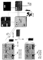
図1は、コールに課金するための移動局MSおよびMS*と、移動無線網の網装置とを有する移動通信システムを示すブロック図である。これらのコールは、移動局MSおよびMS*とを操作する移動体加入者が送受信することができる。移動体加入者の2つの移動局MSとMS*は、無線インタフェースを介して移動無線網の装置にワイヤレスで接続される。ここで移動無線網(例えばGSM規格に準拠する移動無線網)は、無線インタフェースに無線技術サブシステムBSSを有し、このサブシステムBBSは、セルラー構造化された移動無線網の個別の無線セル内に送受信ベース局と、受信局に接続されている基地局制御部とを有する。受信局は、シグナリング情報ないしはメッセージ情報を送受信するために使用され、これらの情報は移動局と網との間でワイヤレスで無線信号を介して交換される。基地局制御部は、無線伝送のための制御技術的な機能、例えばシグナリング情報および/またはメッセージ情報が含まれる伝送チャネルを割り当てるために使用されている。しかし本発明は基本的に、GSM規格とは動作の異なる別の移動通信システムにも適用可能である。
【0020】
無線技術サブシステムBSSには、交換技術サブシステムが接続されており、このサブシステムは通常、シグナリングコネクションおよび/またはメッセージコネクションを移動局にまたは移動局からつなぐための複数の交換技術装置(例えば移動交換局MSC)を有する。この交換技術サブシステムにはさらに、記憶装置(例えば少なくとも1つのホームロケーションレジスタと、1つまたは複数のビジターロケーションレジスタ)が、移動無線網に登録された移動体加入者の加入者データを記憶するために配置されている。ここで移動体加入者の加入者データは、この加入者に割り当てられているホームロケーションレジスタに、この加入者が網に登録されている間は持続的にエントリされている。その一方移動体加入者の加入者データはビジターロケーションレジスタに、所属の移動交換局MSCの担当領域にこの移動体加入者が滞在する間だけ一時的にエントリされる。移動交換局MSCにはこの実施例では関門移動交換局GMSCが接続されており、この関門移動交換局GMSCは、この移動無線網から別の通信網(例えば公衆の加入者線に接続された電話網PSTNまたは別の移動無線網PLMN)へのインタフェースにおけるコネクションを確立する。ここで移動交換局MSCは、移動局MSとMS*とが関係するコールを担当しているとする。さらにコール宛先(被呼される加入者B)は別の網内にあり、移動交換局MSCからのコールコネクションは、関門移動交換局GMSCを経由して、そこから別の網に導びかれる。
【0021】
各々の移動交換局MSCには、課金装置BCが接続されており、この課金装置BCは、発呼した加入者A(ここでは移動局MSを操作する移動体加入者)のコールに関連するデータレコードと、コールされた加入者Bのコールに関連するデータレコードを記録し、その都度のコール料金を、所定のコール料金率を考慮しA側およびB側のデータレコード(Call Data Record)を結びつけることにより求める。ここで各々の移動交換局MSCは、オンライン伝送に対してコール料金を評価するために少なくとも1つのゾーン化/課金表を有しており、このゾーン化/課金表により移動局MS,MS*に料金を指示する。したがってこれはオンライン課金に関する課金装置BCの機能的なコピーである。課金装置BCには管理装置CCC(Customer Care Center)が接続されており、この管理装置は一方では課金装置BCを管理し、他方ではネットワークプロバイダーOPまたはサービスプロバイダーSPの入力を、専用のインタフェースを介して受信する。ネットワークプロバイダーOPまたはサービスプロバイダーSPは課金装置BCに対するアクセスも行い、通常のコール料金率および特殊なコール料金率の実装、変更、または置換を行うことができる。
【0022】
移動局MSとMS*には、各々の移動体加入者に対して1つまたは複数の優先コール番号SN0,SN1およびSny,Snxが定義および管理されている。これらの優先コール番号は、有利には移動体加入者識別モジュールSIMに記憶されており、加入者Aが選択した加入者Bのその都度の宛先コール番号と一致するかどうか比較される。この比較の意味と目的は、網側でのコールの課金を通常の課金とは異なる料金で優先コール番号が存在するかどうかを識別することである。網の重要な処理は例えば、すべての優先コール番号に対して、課金のためにより安いコール料金率を使用することである。選択された優先コール番号の一部に対する料金表のさらなる段階付けは、移動無線網つまり実質的には課金装置BCにより同様に可能である。したがって移動体加入者は、(加入者Bの)宛先コール番号のセットを優先コール番号として設定することができ、この優先コール番号は別の課金構造で、すなわち特別な料金構造であっても網側で処理される。優先コール番号の管理(変更、追加、消去、問い合わせ)は最も簡単な場合には、移動体加入者の加入者本人の入力(Subscriber Cotrolled Input)により行うことができ、この管理に対して場合によっては料金がかけられる。移動無線網は相応のシグナリング情報を移動局に常時送信するため、加入者別の課金であることを示す少なくとも1つの情報および/または発生したコール料金の視覚的/音響的指示も与えることができる。
【0023】
この実施例では各々の移動局MSとMS*にそれぞれ、2つのエントリが番号リストPNLとPNL*(Prefered Number List)に設けられている。各々のエントリは少なくとも1つの優先コール番号と、所属のコール宛先とを有する。優先コール番号は最も簡単な場合、宛先コール番号から成り、この宛先コール番号には、この宛先コール番号が優先コール番号であることを示す標識が配属される。この標識は、すべてのコール番号に対して統一的に使用される記号PNM(Prefered Number Mark)であり、この記号PNMは定義の際に設定され、消去の際には設定が解除される。したがって移動局MSの番号リストPNL内の第1エントリは、宛先コール番号SN0、この宛先コール番号に所属するコール宛先DSTAおよび標識PNMから成る。第2エントリは、所属のコール宛先DSTBを伴う、優先コール番号としての宛先コール番号SN1を有する。これが優先コール番号であるのは同様に標識PNMが設定されているからである。記憶装置の各々のエントリは、優先コール番号SN0,SN1を識別するための短縮コードと、コールした加入者の名前をコール宛先DSTA,DSTBとして含むことができ、これによりこれらのデータを電話帳と同じように移動局側でコールすることができる。同様に移動局MS*内には番号リストPNL*が存在し、この番号リストPNL*の第1エントリは、所属のコール宛先DSTyを伴う優先コール番号SNyと、標識PNMとを含み、その第2エントリは、所属のコール宛先DSTxを伴うコール番号SNxと、標識PNMとを含む。
【0024】
ここで前提としているのは、移動局MSを操作する移動体加入者が、ここから発信したコールを開始し、コールされる加入者B(同様に移動体加入者である。しかし加入者線に接続された加入者であってもよい)の宛先コール番号を選択することである。比較の結果、選択されたコール番号が、記憶された優先コール番号SN0およびSN1のいずれかに一致した場合、加入者別のコールの課金が課金装置BCにより行われる。この実施例では移動体加入者は、優先コール番号の1つであるコール番号SN0を選択している。移動局MS(すべての移動局を代表する)は、移動体加入者に対して優先コール番号SN0,SN1を定義しかつ管理する制御および管理ユニットADMを有する。さらにこの移動局は、比較手段COMを有し、この比較手段COMがコールにより選択された宛先コール番号を、移動体加入者に対して定義されかつSIMモジュールから読み出された優先コール番号SN0,SN1と比較する。宛先コール番号SN0と、2つの優先コール番号SN0,SN1のいずれか1つとの一致が得られることにより、移動局MSはその送受信ユニットTRXにより、コール番号SN0を標識PNMと共に送信する。この送信はシグナリング情報内で、無線サブシステムBSSを介して担当の移動交換局MSCに対して行われる。この移動交換局MSCは、到来する標識PNMに優先コール番号が存在することを読み取る。この標識PNMは課金装置BCに、このコールに対して通常とは別の課金が行われなければならないことを通知する。この異なる処理とは、例えば比較的に少ない料金率PTAR(Prefered Tarif)を課金装置BC内および(オンライン課金のために)移動交換局MSC内で考慮することである。またそうでなければ料金の計算は記録されたデータレコードを用いて公知のように行われる。
【0025】
コールコネクションは、コール宛先DSTAが設定した宛先コール番号に基づいて移動交換局MSCから関門移動交換局GMSCに対して確立される。なぜならば加入者Bは別の通信網PLMN/PSTNの加入者であるからである。最後にコールの終了後、コール合計料金AMOUが得られ、このコール合計料金AMOUが移動体加入者に課金される。課金装置BCは移動交換局MSCにすでに前もって(すなわち場合によってコネクション確立の前、またはそのすぐ後に)、専用の料金率PTARまたは優先課金についての案内を含む少なくとも1つの情報を逆に通知している。移動交換局MSCから、課金に関する情報AOC(Advice of Charge)が、無線サブシステムBSSを介して移動局MSに連続して通知され、この移動局MSは到来する情報から合計料金を計算して加入者に有利には視覚的にディスプレイに表示する。課金に関して優先する処理が存在することを網から移動局へ逆通知することも同様に可能である。この場合、標識PNMを確認のために逆送信することも考えられる。
【0026】
図1とは異なり図2は、移動局MS*と移動無線網との間の情報の通知を示している。なぜならばコールは移動局MS*を操作する移動体加入者から開始されたからである。宛先コール番号は優先コール番号SNxであり、この優先コール番号SNxは標識PNMと共に網の方向に送信される。移動交換局MSCはこの標識を登録し、課金装置BCにコール料金を求めるために優先料金率PTAR*を使用することを指示する。選択されたコール番号により、コール宛先DSTxへのコールコネクションを確立することができる。このコール宛先DSTxはこの実施例では移動体加入者Bに所属し、同じ移動無線網の別の移動交換局MSC*の担当領域に存在する。情報AOCの逆通知は図1の実施例と類似に、同様に網と移動局MS*との間で行われ、これにより移動体加入者はそのコールの専用の料金率について情報を得ることができる。
【0027】
図1および2の図とは択一的に図3は、移動局MSおよびMS*に対する番号リストPNLおよびPNL*を網側に記憶する例を示している。記憶場所は移動無線網の加入者データベースである(有利にはホームロケーションレジスタHLRまたはビジターロケーションレジスタVLRである)。移動体加入者に対するエントリは、図1および2と同様であり、つまり宛先コール番号SN0,SN1およびSNy,SNxは、各々に設定された標識PNMによって優先コール番号として宣言されている。ここで優先コール番号として宣言された宛先コール番号SN0,SN1およびSNy,SNxがすべて固有の表に含まれる場合、標識PNMの記憶を省略することができる。コールした加入者の名前を表すコール宛先DSTA,…,DSTxの記憶はオプション的に網側でも可能である。図1の実施例を引き合いに出すと、移動局MSを介して入力された加入者Bの宛先コール番号SN0は移動交換局MSCに通知される。この移動局MSはコールする側の加入者Aの加入者データに、宛先コール番号に一致する優先コール番号が存在するかどうかを問い合わせ、ホームロケーションレジスタHLRまたは所属のビジターロケーションレジスタVLRから相応の応答情報を受信する。この実施例では宛先コール番号SN0は優先コール番号として定義されておりかつ網側に記憶されているため、移動交換局MSCは課金装置BCに、コール料金を求めるために優先料金表PTARを使用することを通知可能である。選択されたコール番号により、この実施例では別の網の担当領域に存在する、加入者線に接続された加入者のコール宛先DSTAへのコールコネクションが確立される。情報AOCの逆通知は、図1の例と類似に、同様に網と移動局MSとの間で行われ、これにより移動体加入者は、少なくともそのコールの専用の料金率について、または発生した料金について付加的に情報を得ることができる。
【0028】
1つまたは複数の加入者データベース内に網側で記憶された番号リストPNLおよびPNL*は、移動体加入者により加入者本人の入力を介して、またはネットワークプロバイダーOPないしはサービスプロバイダーSPにより課金装置BCないしは管理装置CCCへの専用のインタフェースを介して管理および制御、すなわち変更、補充、消去または問い合わせを行うこともできる。
【0029】
図4は図3とは異なる移動通信システムのブロック図を示しており、ここで移動局MSおよびMS*に対する番号リストPNLおよびPNL*を網側で記憶する択一的なこの実施例の特徴は、インテリジェントネットワーク(IN)のサービス制御局SCP(Service Control Point)にある。これによって優先コール番号を定義および管理することによる柔軟な料金構造を、移動無線網の網構造に依存しないでインテリジェンスのある網機能を実行するために使用されるIN機能を束ねた場合にも達成することができる。記憶場所はサービス制御局SCP内の加入者データベースINDである。移動体加入者のためのエントリは図3と同じ、すなわち宛先コール番号SN0,SN1およびSNy,SNxは優先コール番号として、各々に設定された標識PNMによって宣言されるか、または優先コール番号として優先コール番号表に記憶される。コールした加入者の名前を示すコール宛先DSTA,…,DSTxの記憶を、オプション的に網側で優先させることもできる。
【0030】
図3の例を引き合いに出すと、移動局MSを介して入力された加入者Bの宛先コール番号SN0は移動交換局MSCに通知される(1)。この移動交換局MSCはコール確立時にサービス制御局SCPに分岐し、加入者データベースINDに宛先コール番号に一致する優先コール番号が存在するかどうかを問い合わせる(2)。ここでサービス制御局SCPは、このコールのオンライン課金に関する課金装置BCの機能的なコピーを含んでおり、これは図1および図2の説明と同様である。応答として移動交換局MSCは、移動交換局MSCに宛先コール番号SN0が優先コール番号として定義されており、網側で記憶されていることを確認する情報を受信する(3)。それに基づいて移動交換局MSCは指示を与え、コール料金を求めるために課金装置BCに優先料金率PTARを考慮させる(4)。受信した宛先コール番号SN0によって移動交換局MSCから、加入者線に接続された加入者のコール宛先DSTAへのコールコネクションが確立される。ここでこのコール宛先DSTAはこの実施例では別の網の担当領域にある。課金装置BCは少なくとも専用の料金率PTARについての情報を、移動交換局MSCに返信する(5)。優先的な処理があることを示す情報AOCの、指示(例えば標識PNMからなる)を含めた逆通知は、図3の例と類似に、同様に網と移動局MSとの間で行われ、これにより移動体加入者は、少なくともそのコールの専用の料金について、または発生した料金について付加的に情報を得ることができる。
【0031】
インテリジェントネットワークノードSCPの加入者データベースIND内に網側で記憶された番号リストPNLおよびPNL*は、移動体加入者により移動体加入者本人の入力を介して、またはIN網のネットワークプロバイダーないしはインテリジェントサービスのサービスプロバイダーSPにより(相応のインテリジェント周辺装置によって)課金装置BCないしは管理装置CCCへの専用のインタフェースを介して管理、制御、すなわち変更、補充、消去または問い合わせを行うこともできる。加入者本人の入力を介して、加入者リストPNL,PNL*を移動体加入者が変更することができる。
【0032】
図5のブロック図は、移動局MSおよびMS*に対する番号リストPNL,PNL*を網側で記憶する別の択一的な例を示している。記憶場所は課金装置BCのデータベースBCDである。移動局MSを介する加入者Aのコールは、通常に経過するコールとして処理される。すなわち選択された宛先コール番号SN0は網から通知され、移動交換局MSCにより評価される。課金装置BCにおいてはじめて、データベースBCDに記憶された優先コール番号を含む番号リストを用いて、通常とは異なるコール処理を実行すべきかどうかが決定される。リストPNL,PNL*の両方または一方に記憶された宛先コール番号を、通知されたコール番号と比較して一致という肯定的な結果が得られると、優先コール番号SN0が存在するために別の料金率PTARが、コール合計料金AMOUを求めるために使用される。受信した宛先コール番号SN0に基づいて、移動交換局MSCから加入者線に接続された加入者のコール宛先DSTAへのコールコネクションが確立される。後処理中に読み出されかつ課金装置BC内に網側で記憶された番号リストPNLおよびPNL*は、ネットワークプロバイダーOPないしはサービスプロバイダーSPにより、課金装置BCへの専用のインタフェースを介して管理、制御すなわち変更、補充、消去または問い合わせを行うこともできる。加入者本人の入力を介して、加入者リストPNL,PNL*を移動体加入者が変更することができる。
【0033】
図6は番号リストPNL(これは番号リストPNL*も代表する)に作用するための情報の流れを示している。この作用は一方では移動局MSおよびMS*の側から移動体加入者本人により、他方ではネットワークプロバイダーOPないしはサービスプロバイダーSPの側から行われる。優先コール番号が加入者識別モジュールSIMに存在する場合、加入者は加入者本人の入力SCIを開始する。その一方網側では命令COMがネットワークプロバイダーOPないしはサービスプロバイダーSPにより起動される。番号リストに記憶された情報の制御がどの装置から行われるかには依存しないで、加入者本人による入力SCIと命令COMは、優先コール番号を定義/調整するための情報「create」、優先コール番号を消去するための情報「delete」、優先コール番号を変更するための情報「modify」、または個別またはすべての優先コール番号を問い合わせるための情報「interrogate」を含む。移動局側または網側で受信した制御情報に基づいて標識PNMは設定/解除され、この標識PNMが例えば優先コール番号SN0,SN1または新たな優先コール番号Snzに対して場合によって所属のコール宛先DSTzと共に、既存のリストPNLに追加される。加入者本人による管理および制御の場合に、アクションの結果、網側で求めた料金計算「Bill」が発生することもある。
【図面の簡単な説明】
【図1】 移動局側に記憶された優先コール番号を使用して移動体加入者のコールに課金する移動局と網装置とを備える移動通信システムのブロック図である。
【図2】 移動局側に記憶された優先コール番号を使用して移動体加入者のコールに課金する移動局と網装置とを備える移動通信システムの別のブロック図である。
【図3】 網側で加入者データベースに優先コール番号を記憶してコールに課金する移動通信システムのブロック図である。
【図4】 網側でサービス制御局に優先コール番号を記憶してコールに課金する移動通信システムのブロック図である。
【図5】 網側で課金装置の後処理ユニットに優先コール番号を記憶してコールに課金する移動通信システムのブロック図である。
【図6】 移動局側または網側に記憶された優先コール番号にアクセスするための移動局またはネットワークプロバイダーの通知を示す図である。[0001]
The invention is for charging a call in a mobile radio network comprising a cellular network structure formed from radio cells as described in the superordinate concept of claim 1Mobile communication systemRelated.
[0002]
For example, it is well known that a mobile radio network compliant with the GSM standard (Global System for Mobile Communication) has a cellular network structure in which a plurality of radio cells, which are the minimum radio service area, are gathered. Here, multiple radio cells can be grouped into a location area, the size of which varies depending on the network provider depending on the demands made by traffic density, traffic flow, population density and subscriber mobility. Can also be set. The network provider sets up the wireless network design including the structure, arrangement, number and location area of the wireless cells. In addition, the mobile radio network comprising a cellular network structure may provide signaling information and / ormessageRadio technology equipment for sending and receiving information to and from mobile stations, and signaling connections and / ormessageIt is also known to have an exchange technology device that connects connections. The mobile radio network storage contains subscriber data for registered mobile subscribers, some of whom want to interrupt the call and some who want to wait. At least one charging device is arranged in the mobile radio network to determine the call charge for each call, and the charging device has a data record associated with the call (eg, calling subscriber A and called party). Subscriber B's data record) is recorded, and call charges are calculated depending on this data record. An era in which the number of unregulated networks increases, demand for mobility increases, costs decrease for communication performance, and the cost of providing the last few miles to connect wired subscribers to a fixed network In such a case, it is desirable for a mobile subscriber to have a flexible fee structure by charging a call even in a mobile communication system. If so, a large number of wired subscribers, who are usually paying cheaper than mobile subscribers, can be transferred to mobile communications.
[0003]
The object of the present invention is to improve the mobile communication system so that the billing of calls in the mobile radio network can be better adapted to the mobile subscriber's demands and desires for a more flexible tariff structure. .
[0004]
This problem is solved by the characterizing part of
[0005]
In the present invention, one or more priority call numbers are defined for each mobile subscriber and managed for each subscriber, the destination call number selected by the call, and the priority defined for the mobile subscriber. The call number is compared by subscriber, and if the destination call number matches the priority call number, the call charge is determined for each subscriber separately from the normal charge by the charging device.The priority call numbers (SN0, SN1,..., SNx) are stored on either the mobile station side or the network side, and the stored entries are at least the priority call numbers (SN0, SN1,. Formed from call targets (DSTA, DSTB,..., DTSx), information indicating at least subscriber-specific billing is supplied from the mobile communication network, notified to the mobile station, and the mobile station instructs the mobile subscriber. Is done.By setting a preferred call number for each subscriber, basically each mobile subscriber can select and define a given call destination, which is more advantageous than other calls, for example. Charged by rate. This increases the flexibility of mobile subscribers and network providers for call pricing. Furthermore, the present invention can greatly facilitate the switching exchange of a large number of waiting subscribers to mobile communications. Priority call numbers allow network providers and service providers to provide mobile subscribers with greater flexibility in the rate structure, thus providing a graded rate structure.
[0006]
The present inventionThen, The priority call number is the mobile station side or network sideOne ofIs remembered. On the network side, the priority call number may be stored as subscriber data in at least one subscriber database of the mobile radio network or in at least one subscriber database of the service control station of the intelligent jet network. Storage on the mobile station side has the advantage that the mobile subscriber can change, add, delete, and call the priority call number (eg, via the subscriber's input). In the storage on the network side, the priority call number is managed and controlled by a mobile radio network provider or an intelligent network provider. It is also possible to operate the priority call number stored on the network side through the input of the subscriber himself / herself.
[0007]
It has been found to be particularly advantageous to store the priority call number in the subscriber identity module (SIM) at the mobile station side. In this case, the data entry of the storage device is advantageously formed from a priority call number and at least one call destination to which it belongs.
[0008]
It is also advantageous for the data entry in the storage device to have a short code indicating the preferred call number as well as the name of the called subscriber as the call destination. This corresponds to a telephone number book in a mobile station.
[0009]
Control information indicating that a priority call number exists together with the destination call number is notified from the mobile station to the mobile radio network, so that the mobile radio network can obtain information on the presence of the priority call number. Instructs charging of a call for each subscriber based on the received information.
[0010]
For mobile subscribers, it is advantageous if the mobile radio network is provided with information indicating that the call has been charged at least for each subscriber, which is notified to the mobile station and further directed by the mobile station to the mobile subscriber. It is.
[0011]
According to another development of the present invention, the priority call number can be stored in the billing device on the network side, and only when it is combined with a data record to determine the call charge, consider the presence of the priority call number. Is also possible.
[0013]
Details of the present invention will be described in detail with reference to embodiments shown in the drawings.
[0014]
1 and 2 show block diagrams of a mobile communication system comprising a mobile station and a network device that charge for a mobile subscriber's call using a priority call number stored on the mobile station side.
[0015]
FIG. 3 shows a block diagram of a mobile communication system in which a priority call number is stored in a subscriber database on the network side and a call is charged.
[0016]
FIG. 4 shows a block diagram of a mobile communication system in which a priority call number is stored in a service control station on the network side and a call is charged.
[0017]
FIG. 5 shows a block diagram of a mobile communication system that charges a call by storing a priority call number in a post-processing unit of a charging device on the network side.
[0018]
FIG. 6 shows the signaling of a mobile station or network provider to access a priority call number stored on the mobile station side or network side.
[0019]
FIG. 1 shows mobile stations MS and MS for charging a call.*1 is a block diagram showing a mobile communication system having a mobile radio network device. These calls are for mobile stations MS and MS*The mobile subscriber who operates can transmit and receive. Two mobile stations MS and MS of the mobile subscriber*Is wirelessly connected to the device of the mobile radio network via a radio interface. Here, a mobile radio network (for example, a mobile radio network complying with the GSM standard) has a radio technology subsystem BSS in the radio interface, and this subsystem BBS is located in an individual radio cell of the mobile radio network having a cellular structure. And a base station control unit connected to the receiving station. The receiving station is responsible for signaling information ormessageUsed to send and receive information, which is exchanged wirelessly between mobile stations and the network via radio signals. The base station controller is responsible for control technical functions for radio transmission, eg signaling information and / ormessageUsed to allocate a transmission channel that contains information. However, the present invention is basically applicable to another mobile communication system that operates differently from the GSM standard.
[0020]
Connected to the radio technology subsystem BSS is an exchange technology subsystem, which is usually a signaling connection and / ormessageIt has a plurality of switching technology devices (eg mobile switching center MSC) for connecting the connection to or from the mobile station. The switching technology subsystem further includes a storage device (eg, at least one home location register and one or more visitor location registers) that stores subscriber data of mobile subscribers registered with the mobile radio network. Is arranged for. Here, the subscriber data of the mobile subscriber is continuously entered in the home location register assigned to the subscriber while the subscriber is registered in the network. On the other hand, the subscriber data of the mobile subscriber is temporarily entered in the visitor location register only while this mobile subscriber stays in the area in charge of the mobile switching center MSC to which it belongs. The mobile switching center MSC is connected to a gateway mobile switching center GMSC in this embodiment, and this gateway mobile switching center GMSC is connected to another communication network (for example, a telephone connected to a public subscriber line). Establish a connection at the interface to the network PSTN or another mobile radio network PLMN). Here, the mobile switching center MSC is the mobile station MS and the MS.*Is in charge of a call related to. Furthermore, the call destination (subscriber B called) is in another network, and the call connection from the mobile switching center MSC is routed from there to another network via the gateway mobile switching center GMSC.
[0021]
Each mobile switching center MSC is connected to a billing device BC, which is data related to the call of the calling subscriber A (here, the mobile subscriber operating the mobile station MS). Record the record and the data record related to the call of the called subscriber B, and connect the call charges for each time to the data records (Call Data Record) on the A side and B side in consideration of a predetermined call charge rate By seeking. Here, each mobile switching center MSC has at least one zoning / billing table for evaluating call charges for online transmission, and the zoning / billing table allows the mobile stations MS, MS.*Instruct the fee. This is therefore a functional function of the billing device BC for online billing.Is a copy. A management device CCC (Customer Care Center) is connected to the billing device BC. The management device manages the billing device BC on the one hand, and inputs the network provider OP or service provider SP on the other hand through a dedicated interface. Receive. The network provider OP or the service provider SP can also access the charging device BC, and can implement, change, or replace a normal call rate and a special call rate.
[0022]
Mobile stations MS and MS*Defines and manages one or more priority call numbers SN0, SN1 and Sny, Snx for each mobile subscriber. These priority call numbers are preferably stored in the mobile subscriber identity module SIM and compared to match the respective destination call number of subscriber B selected by subscriber A. The meaning and purpose of this comparison is to identify whether or not a priority call number exists for a charge on the network side at a charge different from the normal charge. An important processing of the network is, for example, to use a lower call rate for billing for all priority call numbers. Further staging of the tariff for a part of the selected priority call number is likewise possible by means of the mobile radio network, ie essentially the charging device BC. Thus, the mobile subscriber can set a set of destination call numbers (of subscriber B) as the preferred call number, which is a different billing structure, i.e. a special toll structure. Processed on the side. In the simplest case, priority call numbers can be managed (changed, added, deleted, inquired) by the Subscriber Controlled Input of the mobile subscriber. Is charged. Mobile radio network is reasonableSignalingSince the information is always transmitted to the mobile station, at least one information indicating a billing by subscriber and / or a visual / acoustic indication of the call charges that have occurred may also be provided.
[0023]
In this embodiment, each mobile station MS and MS*Each has two entries, number lists PNL and PNL*(Prefered Number List). Each entry has at least one priority call number and an associated call destination. In the simplest case, the priority call number is composed of a destination call number, and an indicator indicating that the destination call number is a priority call number is assigned to the destination call number. This sign is a symbol PNM (Preferred Number Mark) used uniformly for all call numbers. This symbol PNM is set at the time of definition, and the setting is canceled at the time of deletion. Therefore, the first entry in the number list PNL of the mobile station MS consists of the destination call number SN0, the call destination DSTA belonging to this destination call number, and the indicator PNM. The second entry has a destination call number SN1 as a priority call number with the call destination DSTB to which it belongs. This is the priority call number because the indicator PNM is similarly set. Each entry in the storage device may contain a short code for identifying the priority call numbers SN0, SN1 and the name of the calling subscriber as the call destination DSTA, DSTB, so that these data are stored in the phone book. Similarly, the mobile station can make a call. Similarly, mobile station MS*In the number list PNL*And this number list PNL*The first entry includes the priority call number SNy with the associated call destination DSTY and the indicator PNM, and the second entry includes the call number SNx with the affiliated call destination DSTx and the indicator PNM.
[0024]
The premise here is that the mobile subscriber operating the mobile station MS initiates a call originating from here and is called subscriber B (also a mobile subscriber, but on the subscriber line). Select a destination call number (which may be a connected subscriber). As a result of the comparison, when the selected call number matches one of the stored priority call numbers SN0 and SN1, the charging for the call for each subscriber is performed by the charging device BC. In this embodiment, the mobile subscriber has selected call number SN0, which is one of the priority call numbers. The mobile station MS (representing all mobile stations) has a control and management unit ADM that defines and manages priority call numbers SN0, SN1 for mobile subscribers. Furthermore, the mobile station has a comparison means COM, which determines the destination call number selected by the call with the priority call number SN0, defined for the mobile subscriber and read from the SIM module. Compare with SN1. By obtaining a match between the destination call number SN0 and one of the two priority call numbers SN0 and SN1, the mobile station MS transmits the call number SN0 together with the indicator PNM by means of its transmission / reception unit TRX. This transmissionSignalingWithin the information, this is done for the mobile switching center MSC in charge via the radio subsystem BSS. The mobile switching center MSC reads that there is a priority call number in the incoming sign PNM. This indicator PNM informs the billing device BC that another billing must be performed for this call. This different processing is, for example, taking into account a relatively low rate PTAR (Preferred Tarif) in the charging device BC and in the mobile switching center MSC (for online charging). Otherwise, the fee calculation is performed in a known manner using the recorded data records.
[0025]
The call connection is established from the mobile switching center MSC to the gateway mobile switching center GMSC based on the destination call number set by the call destination DSTA. This is because subscriber B is a subscriber of another communication network PLMN / PSTN. Finally, after the call is finished, the total call charge AMOU is obtained, and this total call charge AMOU is the mobile subscriber.InCharged. The billing device BC has already notified the mobile switching center MSC in advance (ie, before or after the establishment of the connection as the case may be) with at least one piece of information including a dedicated rate PTAR or guidance on priority billing. . Information about charging AOC (Advice of Charge) is continuously notified from the mobile switching center MSC to the mobile station MS via the radio subsystem BSS, and the mobile station MS calculates the total fee from the incoming information and subscribes. It is advantageously displayed visually on the display. Similarly, it is possible to reversely notify the mobile station from the network that there is a priority process for charging. In this case, it is also conceivable to reversely transmit the sign PNM for confirmation.
[0026]
Unlike FIG. 1, FIG. 2 shows a mobile station MS*And notification of information between mobile radio networks. Because the call is mobile station MS*This is because it was started from a mobile subscriber who operates the. The destination call number is the priority call number SNx, and this priority call number SNx is transmitted in the direction of the network together with the indicator PNM. The mobile switching center MSC registers this indicator and requests the call charge from the charging device BC for the priority rate PTAR.*Instruct to use. A call connection to the call destination DSTx can be established by the selected call number. This call destination DSTx belongs to the mobile subscriber B in this embodiment and is another mobile switching center MSC of the same mobile radio network.*Exists in the responsible area. The reverse notification of the information AOC is similar to the embodiment of FIG.*This allows the mobile subscriber to obtain information about the dedicated rate for the call.
[0027]
As an alternative to the diagrams of FIGS. 1 and 2, FIG.*Number list PNL and PNL for*Is stored on the network side. The storage location is a mobile radio network subscriber database (preferably the home location register HLR or the visitor location register VLR). The entry for the mobile subscriber is similar to that in FIGS. 1 and 2, ie the destination call numbers SN0, SN1 and SNy, SNx are set to each.SignDeclared as priority call number by PNM. If the destination call numbers SN0, SN1 and SNy, SNx declared as priority call numbers are all included in the unique table, the storage of the indicator PNM can be omitted. The call destinations DSTA,..., DSTx representing the name of the calling subscriber can optionally be stored on the network side. When referring to the embodiment of FIG. 1, the destination call number SN0 of the subscriber B input via the mobile station MS is notified to the mobile switching center MSC. This mobile station MS inquires whether there is a priority call number that matches the destination call number in the subscriber data of the calling party A, and responds accordingly from the home location register HLR or the associated visitor location register VLR. Receive information. In this embodiment, since the destination call number SN0 is defined as the priority call number and stored on the network side, the mobile switching center MSCUse priority tariff PTAR to determine call chargesCan be notified. The selected call number establishes a call connection to the call destination DSTA of the subscriber connected to the subscriber line, which in this embodiment is in the area responsible for another network. The reverse notification of the information AOC is performed between the network and the mobile station MS in the same way as in the example of FIG. 1, so that the mobile subscriber has at least incurred or incurred for the call's dedicated rate Additional information can be obtained about the fee.
[0028]
Number lists PNL and PNL stored on the network side in one or more subscriber databases*Is managed and controlled, i.e. changed, supplemented, deleted, by the mobile subscriber via the subscriber's own input or by the network provider OP or service provider SP via the dedicated interface to the charging device BC or the management device CCC. Or you can make an inquiry.
[0029]
FIG. 4 shows a block diagram of a mobile communication system different from FIG. 3, where the mobile stations MS and MS*Number list PNL and PNL for*An alternative feature of this embodiment is that the service control station SCP (Service Control Point) of the intelligent network (IN). This achieves a flexible toll structure by defining and managing priority call numbers, even when bundled with IN functions that are used to perform intelligent network functions independent of the mobile radio network structure. can do. The storage location is the subscriber database IND in the service control station SCP. The entries for the mobile subscriber are the same as in FIG. 3, ie the destination call numbers SN0, SN1 and SNy, SNx are declared as priority call numbers by the respective indicator PNM set or priority as the priority call number Stored in the call number table. Storage of call destinations DSTA,..., DSTx indicating the name of the calling subscriber can optionally be prioritized on the network side.
[0030]
When referring to the example of FIG. 3, the destination call number SN0 of the subscriber B input via the mobile station MS is notified to the mobile switching center MSC (1). The mobile switching center MSC branches to the service control station SCP when the call is established, and inquires whether or not a priority call number matching the destination call number exists in the subscriber database IND (2). Here, the service control station SCP includes a functional copy of the billing device BC for online billing of this call, which is similar to the description of FIGS. In response, the mobile switching center MSC receives information confirming that the destination call number SN0 is defined as a priority call number in the mobile switching center MSC and stored on the network side (3). Based on that, the mobile switching center MSC gives instructions,In order to obtain the call charge, the priority charge rate PTAR is set to the charging device BC.Let them be considered (4). A call connection from the mobile switching center MSC to the call destination DSTA of the subscriber connected to the subscriber line is established by the received destination call number SN0. Here, this call destination DSTA is in a responsible area of another network in this embodiment. The billing device BC returns at least information about the dedicated rate PTAR to the mobile switching center MSC (5). Similar to the example of FIG. 3, the reverse notification of the information AOC indicating that there is priority processing, including an instruction (for example, composed of the label PNM), is performed between the network and the mobile station MS, This allows the mobile subscriber to obtain additional information on at least the dedicated charges for the call or the charges incurred.
[0031]
Number lists PNL and PNL stored on the network side in the subscriber database IND of the intelligent network node SCP*Dedicated to the billing device BC or the management device CCC via the input of the mobile subscriber himself by the mobile subscriber or by the network provider of the IN network or the service provider SP of the intelligent service (with a corresponding intelligent peripheral device) It is also possible to manage, control, i.e. change, replenish, erase or query via the interface. Subscriber list PNL, PNL via subscriber's input*Can be changed by the mobile subscriber.
[0032]
The block diagram of FIG. 5 shows the mobile stations MS and MS*Number list for PNL, PNL*Another alternative example is shown in which is stored on the network side. The storage location is the database BCD of the billing device BC. Subscriber A's call via the mobile station MS is treated as a normal elapse call. That is, the selected destination call number SN0 is notified from the network and evaluated by the mobile switching center MSC. For the first time in the billing device BC, it is determined whether or not to perform call processing different from normal using a number list including priority call numbers stored in the database BCD. List PNL, PNL*If the destination call number stored in one or both of the destinations is compared with the notified call number and a positive result is obtained, another rate rate PTAR is displayed due to the presence of the priority call number SN0. Used to determine total fee AMOU. Based on the received destination call number SN0, a call connection is established from the mobile switching center MSC to the call destination DSTA of the subscriber connected to the subscriber line. Number lists PNL and PNL read during post-processing and stored on the network side in the billing device BC*Can also be managed, controlled, i.e. changed, supplemented, deleted or queried by the network provider OP or service provider SP via a dedicated interface to the billing device BC. Subscriber list PNL, PNL via subscriber's input*Can be changed by the mobile subscriber.
[0033]
FIG. 6 shows a number list PNL (this is a number list PNL*The flow of information for acting on the This effect is on the one hand mobile stations MS and MS*On the other hand from the mobile subscriber himself, on the other hand from the network provider OP or service provider SP side. If the priority call number is present in the subscriber identity module SIM, the subscriber initiates the subscriber's own input SCI. On the other hand, on the network side, the command COM is activated by the network provider OP or the service provider SP. Regardless of the device from which the information stored in the number list is controlled, the input SCI and the command COM by the subscriber himself / herself are information “create” for defining / adjusting the priority call number, priority call Information “delete” for deleting the number, information “modify” for changing the priority call number, or information “interrogate” for inquiring individual or all priority call numbers are included. Based on the control information received at the mobile station side or the network side, the indicator PNM is set / released, and this indicator PNM may be associated with the priority call number SN0, SN1 or the new priority call number Snz depending on the case, for example. At the same time, it is added to the existing list PNL. In the case of management and control by the subscriber himself / herself, the charge calculation “Bill” obtained on the network side may occur as a result of the action.
[Brief description of the drawings]
FIG. 1 is a block diagram of a mobile communication system including a mobile station and a network device that charge for a mobile subscriber's call using a priority call number stored on the mobile station side.
FIG. 2 is another block diagram of a mobile communication system including a mobile station and a network device that charge for a mobile subscriber's call using a priority call number stored on the mobile station side.
FIG. 3 is a block diagram of a mobile communication system in which a priority call number is stored in a subscriber database on a network side and a call is charged.
FIG. 4 is a block diagram of a mobile communication system that charges a call by storing a priority call number in a service control station on the network side.
FIG. 5 is a block diagram of a mobile communication system that charges a call by storing a priority call number in a post-processing unit of a charging device on the network side.
FIG. 6 is a diagram showing notification of a mobile station or a network provider for accessing a priority call number stored on the mobile station side or the network side.
Claims (15)
該移動通信システムは、無線セルから形成されたセルラー方式の網構造を有する移動無線網内の移動通信システムであり、
シグナリング情報またはメッセージ情報を移動局(MS,MS*)に送信または移動局(MS,MS*)から受信する無線技術装置(BSS)と、
シグナリングコネクションまたはメッセージコネクションをつなぐ交換技術装置(MSC)と、
移動体加入者の加入者データを記憶する記憶装置と、
コールに関係するデータレコードを記録してその都度のコール料金を前記データレコードに依存して求める課金装置(BC)とを有する形式の移動通信システムにおいて、
移動体加入者に対してそれぞれ1つまたは複数の優先コール番号(SN0,SN1,…,SNx)が定義および加入者別に管理され、
少なくとも加入者別の課金を示す情報(AOC)が、移動通信網から供給され、移動局(MS,MS*)に通知され、該移動局(MS,MS*)から移動体加入者に表示され、
優先コール番号であることを示す制御情報(PNM)が割り当てられかつコールにより選択された宛先コール番号と、移動体加入者に対して定義された前記優先コール番号(SN0,SN1,…,SNx)とが加入者別に比較され、
前記宛先コール番号が前記優先コール番号(SN0,SN1,…,SNx)と一致した場合、コール料金(AMOU)が前記課金装置(BC)により、通常の課金とは異なる料金で加入者別に求められることを特徴とする
移動通信システム。A communication system for charging a call that can be transmitted and received from a mobile station (MS, MS * ) of a mobile subscriber,
The mobile communication system is a mobile communication system in a mobile radio network having a cellular network structure formed from radio cells,
A radio technology device (BSS) for transmitting signaling information or message information to a mobile station (MS, MS * ) or receiving from the mobile station (MS, MS * );
Switching technology equipment (MSC) that connects signaling or message connections ;
A storage device for storing subscriber data of mobile subscribers;
In a mobile communication system having a billing device (BC) that records a data record related to a call and obtains a call charge for each call depending on the data record,
One or more priority call numbers (SN0, SN1,..., SNx) for each mobile subscriber are defined and managed per subscriber,
Information indicating at least the individual subscriber charging (AOC) are supplied from the mobile communication network is notified to the mobile station (MS, MS *), is displayed to the mobile subscriber from the mobile station (MS, MS *) ,
A destination call number assigned with control information (PNM) indicating a priority call number and selected by the call, and the priority call number (SN0, SN1,..., SNx) defined for the mobile subscriber Are compared by subscriber,
When the destination call number matches the priority call number (SN0, SN1,..., SNx), the call charge (AMOU) is obtained by the charging device (BC) for each subscriber at a charge different from the normal charge. A mobile communication system.
請求項1に記載の移動通信システム。The mobile communication system according to claim 1, wherein the priority call numbers (SN0, SN1, ..., SNx) are stored on a mobile station side.
請求項2に記載の移動通信システム。The priority call numbers (SN0, SN1,..., SNx) are stored in a mobile station (MS, MS * ) or a subscriber identification module (SIM) of the mobile station (MS, MS * ). The mobile communication system described.
請求項2または3に記載の移動通信システム。The stored entry is formed from at least a priority call number (SN0, SN1, ..., SNx) and a call destination (DSTA, DSTB, ..., DTSx) assigned to the priority call number. 4. The mobile communication system according to 3.
請求項4に記載の移動通信システム。5. The stored entry includes a short code indicating a priority call number (SN0, SN1,..., SNx) and the name of the called subscriber as a call destination (DSTA, DSTB,..., DSTx). The mobile communication system according to 1.
該移動無線網内で、受信した情報に基づくコールの加入者別の課金が指示される
請求項2から5までのいずれか1項に記載の移動通信システム。Control information (PNM) indicating the presence of priority call numbers (SN0, SN1,..., SNx) is notified from the mobile station (MS) to the mobile radio network together with the destination call number ,
The mobile communication system according to any one of claims 2 to 5, wherein charging for each subscriber of a call based on the received information is instructed in the mobile radio network.
請求項1または6に記載の移動通信システム。The mobile communication according to claim 1 or 6, wherein the information (PNM) indicating that a priority call number (SN0, SN1, ..., SNx) exists is notified to and displayed on a mobile station (MS, MS *). system.
請求項1に記載の移動通信システム。The mobile communication system according to claim 1, wherein the priority call numbers (SN0, SN1, ..., SNx) are stored on a network side.
請求項8に記載の移動通信システム。9. The priority call numbers (SN0, SN1,..., SNx) are stored as subscriber data for individual subscribers in at least one subscriber database (HLR, VLR) of a mobile radio network. Mobile communication system.
請求項8に記載の移動通信システム。9. The priority call numbers (SN0, SN1,..., SNx) are stored for each subscriber in at least one subscriber database (IND) of an intelligent network service control station (SCP). The mobile communication system according to 1.
請求項9または10に記載の移動通信システム。The priority call numbers (SN0, SN1,..., SNx) entered as subscriber data are managed by the network provider (OP) of the mobile communication network or stored in the service control station (SCP). The mobile communication system according to claim 9 or 10, wherein call numbers (SN0, SN1, ..., SNx) are managed by a network provider (OP) of the intelligent network.
請求項8から10までのいずれか1項に記載の移動通信システム。11. The priority call numbers (SN0, SN1,..., SNx) are managed by a mobile station (MS, MS * ) via input (SCI) by a subscriber's own subscriber. The mobile communication system according to claim 1.
請求項12に記載の移動通信システム。13. The mobile communication system according to claim 12, wherein an input (SCI) by the subscriber himself / herself for managing priority call numbers (SN0, SN1,..., SNx) is separately charged to the subscriber.
コール料金を求めるためにデータレコードの結合時にはじめて、優先コール番号(SN0,SN1,…,SNx)の存在が考慮される
請求項1に記載の移動通信システム。The priority call numbers (SN0, SN1,..., SNx) are stored in the charging device (BC) on the network side,
The mobile communication system according to claim 1, wherein the presence of priority call numbers (SN0, SN1, ..., SNx) is considered only when data records are combined in order to obtain a call charge.
請求項8から14までのいずれか1項に記載の移動通信システム。The priority call numbers (SN0, SN1,..., SNx) cause the addition of a new priority call number, the removal of the stored priority call number, the change of the stored priority number or the inquiry of the stored priority call number. The mobile communication system according to any one of claims 8 to 14, wherein the mobile communication system is managed via signaling information.
Applications Claiming Priority (3)
| Application Number | Priority Date | Filing Date | Title |
|---|---|---|---|
| DE19735950A DE19735950C1 (en) | 1997-08-19 | 1997-08-19 | Mobile communication system for charging for calls and mobile station |
| DE19735950.7 | 1997-08-19 | ||
| PCT/DE1998/002401 WO1999009763A1 (en) | 1997-08-19 | 1998-08-18 | Mobile communications system for pricing calls and mobile station |
Related Child Applications (1)
| Application Number | Title | Priority Date | Filing Date |
|---|---|---|---|
| JP2005028015A Division JP4170992B2 (en) | 1997-08-19 | 2005-02-03 | Mobile station for billing calls |
Publications (3)
| Publication Number | Publication Date |
|---|---|
| JP2001516191A JP2001516191A (en) | 2001-09-25 |
| JP2001516191A5 JP2001516191A5 (en) | 2008-01-17 |
| JP4112803B2 true JP4112803B2 (en) | 2008-07-02 |
Family
ID=7839442
Family Applications (2)
| Application Number | Title | Priority Date | Filing Date |
|---|---|---|---|
| JP2000510293A Expired - Lifetime JP4112803B2 (en) | 1997-08-19 | 1998-08-18 | Mobile communication system for billing calls |
| JP2005028015A Expired - Lifetime JP4170992B2 (en) | 1997-08-19 | 2005-02-03 | Mobile station for billing calls |
Family Applications After (1)
| Application Number | Title | Priority Date | Filing Date |
|---|---|---|---|
| JP2005028015A Expired - Lifetime JP4170992B2 (en) | 1997-08-19 | 2005-02-03 | Mobile station for billing calls |
Country Status (7)
| Country | Link |
|---|---|
| US (1) | US6553217B1 (en) |
| EP (1) | EP1005764B1 (en) |
| JP (2) | JP4112803B2 (en) |
| CN (1) | CN1104164C (en) |
| DE (2) | DE19735950C1 (en) |
| ES (1) | ES2229541T3 (en) |
| WO (1) | WO1999009763A1 (en) |
Families Citing this family (22)
| Publication number | Priority date | Publication date | Assignee | Title |
|---|---|---|---|---|
| US6324404B1 (en) * | 1991-12-26 | 2001-11-27 | Sycord Limited Partnership | Cellular telephone system that uses position of a mobile unit to make call management decisions |
| DE19827285A1 (en) * | 1998-06-19 | 1999-12-23 | Alcatel Sa | Method, server and communication node for establishing fee-optimized communication connections |
| DE10004742A1 (en) * | 2000-01-28 | 2001-08-09 | Siemens Ag | Method for establishing and billing a telecommunication connection |
| US6900320B2 (en) * | 2000-07-24 | 2005-05-31 | Matsushita Electric Industrial Co., Ltd. | Personal information control system |
| DE10109908A1 (en) * | 2001-02-20 | 2002-08-29 | Siemens Ag | Method and account management system for billing services performed in a telecommunications network |
| GB2379832B (en) * | 2001-09-15 | 2004-01-07 | Motorola Inc | A cellular communication system,billing processor and method of billing therefor |
| SE0201315L (en) * | 2002-04-30 | 2003-10-31 | Ericsson Telefon Ab L M | A method and system for rate calculation in a billing system |
| JP2007521709A (en) * | 2003-12-23 | 2007-08-02 | テレフオンアクチーボラゲット エル エム エリクソン(パブル) | Rating notification method and system |
| KR100809144B1 (en) | 2004-03-12 | 2008-03-03 | 닛본 덴끼 가부시끼가이샤 | Communication charge system, ultra-small radio base station, communication charge method, and recording medium having recorded a program therein |
| US7328001B2 (en) * | 2004-08-05 | 2008-02-05 | International Business Machines Corporation | Traffic shaping of cellular service consumption through modification of consumer behavior encouraged by cell-based pricing advantages |
| US8175534B2 (en) | 2004-09-03 | 2012-05-08 | Cisco Technology, Inc. | RF-aware packet filtering in radio access networks |
| US8078463B2 (en) * | 2004-11-23 | 2011-12-13 | Nice Systems, Ltd. | Method and apparatus for speaker spotting |
| US20060179064A1 (en) * | 2005-02-07 | 2006-08-10 | Nice Systems Ltd. | Upgrading performance using aggregated information shared between management systems |
| US8725518B2 (en) * | 2006-04-25 | 2014-05-13 | Nice Systems Ltd. | Automatic speech analysis |
| WO2007135656A1 (en) * | 2006-05-18 | 2007-11-29 | Nice Systems Ltd. | Method and apparatus for combining traffic analysis and monitoring center in lawful interception |
| CN101119410B (en) * | 2006-08-01 | 2012-02-15 | 华为技术有限公司 | Method and system for implementing fee prompting supplementary service |
| CN101594585A (en) * | 2008-05-30 | 2009-12-02 | 鸿富锦精密工业(深圳)有限公司 | Seek the system and method for cheapest talking mode |
| CN102217275A (en) * | 2008-11-18 | 2011-10-12 | 思达伦特网络有限责任公司 | Selective paging in wireless networks |
| US8428625B2 (en) | 2009-02-27 | 2013-04-23 | Cisco Technology, Inc. | Paging heuristics in packet based networks |
| US8861535B2 (en) | 2010-05-21 | 2014-10-14 | Cisco Technology, Inc. | Multi-tiered paging support using paging priority |
| US8537829B2 (en) | 2010-09-15 | 2013-09-17 | Cisco Technology, Inc. | Paging control in communication networks |
| US9060347B2 (en) | 2012-11-30 | 2015-06-16 | Cisco Technology, Inc. | Subscriber-aware paging |
Family Cites Families (8)
| Publication number | Priority date | Publication date | Assignee | Title |
|---|---|---|---|---|
| US6324404B1 (en) * | 1991-12-26 | 2001-11-27 | Sycord Limited Partnership | Cellular telephone system that uses position of a mobile unit to make call management decisions |
| DE4419651C2 (en) * | 1994-06-04 | 1998-01-29 | Deutsche Telekom Mobil | Procedure for calculating fees |
| US5509056A (en) * | 1994-06-06 | 1996-04-16 | Ericsson Ge Mobile Communications Inc. | Method and apparatus for executing automatic calling card access in cellular telephones |
| EP0734144A3 (en) * | 1995-03-20 | 1999-08-18 | Siemens Aktiengesellschaft | Method and apparatus for determination of user charges in a subscriber apparatus |
| US6018652A (en) * | 1995-08-31 | 2000-01-25 | Telefonaktiebolaget Lm Ericsson (Publ.) | Cellular telephone system having mobile charging region and area based pricing method and apparatus |
| FI2405U1 (en) * | 1995-12-20 | 1996-04-23 | Finland Telecom Oy | A system for making specially priced calls on a telecommunications network |
| DE19608419C2 (en) * | 1996-03-05 | 1998-06-10 | Deutsche Telekom Mobil | Method for establishing a connection and for billing connections in telecommunications networks for specific destination numbers that can be individually selected by the subscriber |
| US6397055B1 (en) * | 1999-12-20 | 2002-05-28 | Bell Atlantic Mobile | Mobile to mobile call delivery for calling party pays wireless service |
-
1997
- 1997-08-19 DE DE19735950A patent/DE19735950C1/en not_active Expired - Fee Related
-
1998
- 1998-08-18 US US09/485,891 patent/US6553217B1/en not_active Expired - Lifetime
- 1998-08-18 EP EP98951163A patent/EP1005764B1/en not_active Expired - Lifetime
- 1998-08-18 DE DE59812154T patent/DE59812154D1/en not_active Expired - Lifetime
- 1998-08-18 CN CN98808354A patent/CN1104164C/en not_active Expired - Lifetime
- 1998-08-18 WO PCT/DE1998/002401 patent/WO1999009763A1/en active IP Right Grant
- 1998-08-18 ES ES98951163T patent/ES2229541T3/en not_active Expired - Lifetime
- 1998-08-18 JP JP2000510293A patent/JP4112803B2/en not_active Expired - Lifetime
-
2005
- 2005-02-03 JP JP2005028015A patent/JP4170992B2/en not_active Expired - Lifetime
Also Published As
| Publication number | Publication date |
|---|---|
| WO1999009763A1 (en) | 1999-02-25 |
| JP4170992B2 (en) | 2008-10-22 |
| ES2229541T3 (en) | 2005-04-16 |
| DE19735950C1 (en) | 1999-04-22 |
| JP2001516191A (en) | 2001-09-25 |
| CN1104164C (en) | 2003-03-26 |
| EP1005764B1 (en) | 2004-10-20 |
| CN1267434A (en) | 2000-09-20 |
| EP1005764A1 (en) | 2000-06-07 |
| JP2005192235A (en) | 2005-07-14 |
| DE59812154D1 (en) | 2004-11-25 |
| US6553217B1 (en) | 2003-04-22 |
Similar Documents
| Publication | Publication Date | Title |
|---|---|---|
| JP4170992B2 (en) | Mobile station for billing calls | |
| CN100385899C (en) | Device and method for indication of charging information using USSD mechanism | |
| CN101990745B (en) | Call processing system for mobile and method thereof | |
| CN100358392C (en) | System and method for realizing calling to international wandering user by local virtual number | |
| US5517549A (en) | Call logging in cellular subscriber stations | |
| US5592535A (en) | Mobile-radio network with debit accounts | |
| US7627315B2 (en) | Telecommunications method and suitable system for establishing a connection with a mobile device | |
| JP2802968B2 (en) | Method for establishing a connection between a calling subscriber in a telecommunications network and a called mobile target subscriber in a mobile radio network | |
| US6975855B1 (en) | Method for managing mobile station facilities | |
| CN1231107A (en) | Cellular telephone network routing method and apparatus for internationally roaming mobile station | |
| JP3676423B2 (en) | Information communication system | |
| EP1346517B1 (en) | Charge advice in telecommunication systems | |
| CN1308812A (en) | Call prepayment in a telecommunication system | |
| US6253072B1 (en) | Method and system for dynamically updating rate center information | |
| EP1281270B1 (en) | Distributed pre-paid communications infrastructure | |
| EP1216589B1 (en) | Handling of short messages in a telecommunication system | |
| IL125010A (en) | Procedure and system for the setting up of calls | |
| JP2001007947A (en) | Charge report information delivery system | |
| JPH08130594A (en) | Selecting method for route of call charge discount service and lcr device | |
| EP2071763A1 (en) | Method, system and agent server for charging data services | |
| CN102308602B (en) | Method and platform of simulation of fixed line telephone and communication system | |
| US6856675B1 (en) | Process for signalling cost information upon connection establishment and a tariff server therefor | |
| CN101730316A (en) | Method, system and device for switching number | |
| JPH06245255A (en) | Mobile communication method and communication system based on personal information | |
| CN100438650C (en) | CDMA network heat charging method |
Legal Events
| Date | Code | Title | Description |
|---|---|---|---|
| A521 | Written amendment |
Free format text: JAPANESE INTERMEDIATE CODE: A523 Effective date: 20040213 |
|
| A02 | Decision of refusal |
Free format text: JAPANESE INTERMEDIATE CODE: A02 Effective date: 20041001 |
|
| A521 | Written amendment |
Free format text: JAPANESE INTERMEDIATE CODE: A523 Effective date: 20050203 |
|
| A911 | Transfer to examiner for re-examination before appeal (zenchi) |
Free format text: JAPANESE INTERMEDIATE CODE: A911 Effective date: 20050215 |
|
| A912 | Re-examination (zenchi) completed and case transferred to appeal board |
Free format text: JAPANESE INTERMEDIATE CODE: A912 Effective date: 20050408 |
|
| A601 | Written request for extension of time |
Free format text: JAPANESE INTERMEDIATE CODE: A601 Effective date: 20070807 |
|
| A602 | Written permission of extension of time |
Free format text: JAPANESE INTERMEDIATE CODE: A602 Effective date: 20070810 |
|
| A601 | Written request for extension of time |
Free format text: JAPANESE INTERMEDIATE CODE: A601 Effective date: 20070906 |
|
| A602 | Written permission of extension of time |
Free format text: JAPANESE INTERMEDIATE CODE: A602 Effective date: 20070911 |
|
| A601 | Written request for extension of time |
Free format text: JAPANESE INTERMEDIATE CODE: A601 Effective date: 20071009 |
|
| A602 | Written permission of extension of time |
Free format text: JAPANESE INTERMEDIATE CODE: A602 Effective date: 20071015 |
|
| A711 | Notification of change in applicant |
Free format text: JAPANESE INTERMEDIATE CODE: A711 Effective date: 20071031 |
|
| A521 | Written amendment |
Free format text: JAPANESE INTERMEDIATE CODE: A523 Effective date: 20071109 |
|
| A524 | Written submission of copy of amendment under section 19 (pct) |
Free format text: JAPANESE INTERMEDIATE CODE: A524 Effective date: 20071109 |
|
| A61 | First payment of annual fees (during grant procedure) |
Free format text: JAPANESE INTERMEDIATE CODE: A61 Effective date: 20080410 |
|
| R150 | Certificate of patent or registration of utility model |
Free format text: JAPANESE INTERMEDIATE CODE: R150 |
|
| FPAY | Renewal fee payment (event date is renewal date of database) |
Free format text: PAYMENT UNTIL: 20110418 Year of fee payment: 3 |
|
| FPAY | Renewal fee payment (event date is renewal date of database) |
Free format text: PAYMENT UNTIL: 20110418 Year of fee payment: 3 |
|
| FPAY | Renewal fee payment (event date is renewal date of database) |
Free format text: PAYMENT UNTIL: 20120418 Year of fee payment: 4 |
|
| FPAY | Renewal fee payment (event date is renewal date of database) |
Free format text: PAYMENT UNTIL: 20120418 Year of fee payment: 4 |
|
| FPAY | Renewal fee payment (event date is renewal date of database) |
Free format text: PAYMENT UNTIL: 20130418 Year of fee payment: 5 |
|
| FPAY | Renewal fee payment (event date is renewal date of database) |
Free format text: PAYMENT UNTIL: 20130418 Year of fee payment: 5 |
|
| FPAY | Renewal fee payment (event date is renewal date of database) |
Free format text: PAYMENT UNTIL: 20140418 Year of fee payment: 6 |
|
| R250 | Receipt of annual fees |
Free format text: JAPANESE INTERMEDIATE CODE: R250 |
|
| S533 | Written request for registration of change of name |
Free format text: JAPANESE INTERMEDIATE CODE: R313533 |
|
| R350 | Written notification of registration of transfer |
Free format text: JAPANESE INTERMEDIATE CODE: R350 |
|
| R250 | Receipt of annual fees |
Free format text: JAPANESE INTERMEDIATE CODE: R250 |
|
| R250 | Receipt of annual fees |
Free format text: JAPANESE INTERMEDIATE CODE: R250 |
|
| R250 | Receipt of annual fees |
Free format text: JAPANESE INTERMEDIATE CODE: R250 |
|
| R250 | Receipt of annual fees |
Free format text: JAPANESE INTERMEDIATE CODE: R250 |
|
| EXPY | Cancellation because of completion of term |