JP4097867B2 - Information recording / reproducing apparatus and information recording method - Google Patents
Information recording / reproducing apparatus and information recording method Download PDFInfo
- Publication number
- JP4097867B2 JP4097867B2 JP36421599A JP36421599A JP4097867B2 JP 4097867 B2 JP4097867 B2 JP 4097867B2 JP 36421599 A JP36421599 A JP 36421599A JP 36421599 A JP36421599 A JP 36421599A JP 4097867 B2 JP4097867 B2 JP 4097867B2
- Authority
- JP
- Japan
- Prior art keywords
- recording
- information
- disk
- type
- standard
- Prior art date
- Legal status (The legal status is an assumption and is not a legal conclusion. Google has not performed a legal analysis and makes no representation as to the accuracy of the status listed.)
- Expired - Lifetime
Links
Images


Classifications
-
- G—PHYSICS
- G11—INFORMATION STORAGE
- G11B—INFORMATION STORAGE BASED ON RELATIVE MOVEMENT BETWEEN RECORD CARRIER AND TRANSDUCER
- G11B19/00—Driving, starting, stopping record carriers not specifically of filamentary or web form, or of supports therefor; Control thereof; Control of operating function ; Driving both disc and head
- G11B19/02—Control of operating function, e.g. switching from recording to reproducing
- G11B19/12—Control of operating function, e.g. switching from recording to reproducing by sensing distinguishing features of or on records, e.g. diameter end mark
-
- G—PHYSICS
- G11—INFORMATION STORAGE
- G11B—INFORMATION STORAGE BASED ON RELATIVE MOVEMENT BETWEEN RECORD CARRIER AND TRANSDUCER
- G11B7/00—Recording or reproducing by optical means, e.g. recording using a thermal beam of optical radiation by modifying optical properties or the physical structure, reproducing using an optical beam at lower power by sensing optical properties; Record carriers therefor
- G11B7/004—Recording, reproducing or erasing methods; Read, write or erase circuits therefor
- G11B7/0045—Recording
Description
【0001】
【発明の属する技術分野】
本発明は、記録媒体に情報データの記録を行う情報記録再生装置に関する。
【0002】
【背景技術】
現在、情報データの書き込みが可能な光学式記録媒体として、追記型のCD(Compact Disc)−R、DVD(Digital Versatile Disc)−R、並びに、書き換え可能なDVD−RW等の記録ディスクが着目されている。
情報記録装置は、上記記録ディスクに対して情報データの書き込みを行うにあたり、例えば以下の如き処理を実施する。
【0003】
先ず、情報データに応じたレベル変化を有する記録信号を生成し、これを書込用レーザダイオードに供給する。書込用レーザダイオードは、上記記録信号のレベルに応じた光パワーを有するレーザビーム光を発生し、これを記録ディスクの記録面上に照射する。この際、レーザビーム光の照射された領域は、照射されていない領域に比してその反射率が低下し、この反射率の低下した領域が情報データを担う記録ピットとなる。
【0004】
ところが、記録ディスクの構造及び材質等の違いによって、上記レーザビーム光の照射によって形成される記録ピットの形状にはばらつきが生じる。
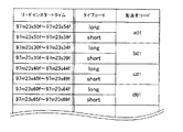
そこで、追記型の記録ディスクであるCD−Rの規格、いわゆるオレンジブックでは、CD−Rを、図1に示されるが如きメディアタイプ(タイプA〜C)と、βカテゴリ(high、low)との組み合わせに基づく6種類のディスクタイプ(以下、共有ディスクタイプと称する)に分類し、各製造者共有で採用するように規定している。
【0005】
例えば、CD−Rの製造元では、先ず、上記6種類のCD−Rのいずれに対しても情報記録を行うことが出来る標準記録装置を用いて自社の製造したCD−Rに情報データの記録を行い、その記録結果により、このCD−Rが上記6種類の共有ディスクタイプのいずれに該当するのかを判断する。CD−Rの製造元は、かかる判断結果によって得られた共有ディスクタイプ(メディアタイプ+βカテゴリ)をこのCD−Rに記録して出荷する。
【0006】
一方、この出荷されたCD−Rに対して情報データの記録を行う記録装置側では、上記6種類の共有ディスクタイプ各々に対して、図1に示されるが如き最適な記録信号を生成するためのストラテジである第1記録規格による波形パラメータ(ΔPD、ΔPH、θT)を設定しておく。かかる第1記録規格によれば、情報データ信号を担う例えば図2(a)に示されるが如き3T−EFM(Eight to Fourteen Modulation)変調信号は、図2(b)に示されるが如き波形を有する記録信号に変換される。図2(b)に示されるように、かかる記録信号波形は、先ず、EFM変調信号の立ち上がりから時間θTの遅れを持って立ち上がる。そして、ΔPDの期間に亘り、記録パワーPWよりΔPHだけ高い記録パワーを維持し、その後、EFM変調信号の立ち下がりまで記録パワーPWのレベルに保たれている。つまり、記録装置側では、装着されたCD−Rから上記共有ディスクタイプを読み取り、その共有ディスクタイプに対応した記録規格に従った波形を有する記録信号を生成して上記書込用レーザダイオードを駆動することにより、良好な形状を有する記録ピットの形成を実現するのである。
【0007】
すなわち、オレンジブックでは、上記6種類の共有ディスクタイプのいずれかに該当するCD−Rを製造するように、製造元を促しているのである。
【0008】
【発明が解決しようとする課題】
しかしながら、CD−Rの製造会社によっては、製造したCD−Rを上記6種類の共有ディスクタイプに該当させてはいるものの、必ずしもこの共有ディスクタイプが最善とはならないCD−Rを製造している場合がある。
【0009】
【課題を解決するための手段】
本発明は、かかる問題を解決せんとして為されたものであり、より良好な形状を有する記録ピットを形成し得る情報記録再生装置及び情報記録方法を提供することを目的とする。
請求項1記載による情報記録再生装置は、情報データを担う記録信号に応じた記録ビーム光を記録ディスクに照射することにより前記記録ディスクに対して情報記録を行なう情報記録再生装置であって、記録ディスクの各種のディスクタイプを示す共有ディスクタイプと前記記録信号を生成する際の第1記録規格の波形パラメータとが対応付けされている第1記録規格情報と、記録ディスクの各製造者を示す製造者コード及びピット形成の反応性を示すタイプコードと前記記録信号を生成する際の第2記録規格の波形パラメータとが対応付けされている第2記録規格情報と、が記憶されている記憶手段と、前記記録ディスクに記録されている共有ディスクタイプ及びリードインスタートタイムを夫々読み取る手段と、前記記録ディスクから読み取られた共有ディスクタイプ及びリードインスタートタイムに基づいて、前記第1記録規格情報及び前記第2記録規格情報から前記波形パラメータの1つを選択し、この波形パラメータに基づいて前記記録信号の生成を行う記録信号生成手段と、を有する。
又、請求項2記載による情報記録再生装置は、情報データを担う記録信号に応じた記録ビーム光を記録ディスクに照射することにより前記記録ディスクに対して情報記録を行なう情報記録再生装置であって、記録ディスクの各種のディスクタイプを示す共有ディスクタイプと前記記録信号を生成する際の第1記録規格の波形パラメータとが対応付けされている第1記録規格情報と、記録ディスクの各製造者を示す製造者コード及びピット形成の反応性を示すタイプコードと前記記録信号を生成する際の第2記録規格の波形パラメータとが対応付けされている第2記録規格情報と、前記製造者コードの各々とリードインスタートタイム及びタイプコードとが夫々対応付けされている製造者コード情報と、が夫々記憶されている記憶手段と、前記記録ディスクに記録されている共有ディスクタイプ及びリードインスタートタイムを夫々読み取る手段と、前記記録ディスクから読み取られた前記リードインスタートタイムに対応した前記製造者コードを前記製造者コード情報から検索し、この検索された前記製造者コードと前記記録ディスクから読み取られた前記共有ディスクタイプとに基づいて、前記第1記録規格情報及び前記第2記録規格情報各々の内から前記波形パラメータの1つを選択しこの波形パラメータに基づいて前記記録信号の生成を行う記録信号生成手段と、を有する。
【0010】
又、請求項8記載による情報記録方法は、情報データを担う記録信号に応じた記録ビーム光を記録ディスクに照射することにより前記記録ディスクに対して情報記録を行なう情報記録方法であって、
記録ディスクの各種のディスクタイプを示す共有ディスクタイプと前記記録信号を生成する際の第1記録規格の波形パラメータとが対応付けされている第1記録規格情報と、記録ディスクの各製造者を示す製造者コード及びピット形成の反応性を示すタイプコードと前記記録信号を生成する際の第2記録規格の波形パラメータとが対応付けされている第2記録規格情報と、前記製造者コードの各々とリードインスタートタイム及びタイプコードとが夫々対応付けされている製造者コード情報と、が夫々記憶されている記憶手段から、前記第1記録規格情報、前記第2記録規格情報及び前記製造者コード情報を読み出す行程と、前記記録ディスクに記録されている共有ディスクタイプ及びリードインスタートタイムを夫々読み取る行程と、前記記録ディスクから読み取られた前記リードインスタートタイムに対応した前記製造者コードを前記製造者コード情報から検索し、この検索された前記製造者コードと前記記録ディスクから読み取られた前記共有ディスクタイプとに基づいて、前記第1記録規格情報及び前記第2記録規格情報各々の内から前記波形パラメータの1つを選択しこの波形パラメータに基づいて前記記録信号の生成を行う行程と、を有する。
【0011】
【発明の実施の形態】
図3は、本発明による情報記録再生装置の構成を示す図である。
図3において、記録変調回路11は、映像信号、音声信号又はコンピュータデータ信号の如き情報データ信号に所定の記録用変調処理を施し、この際得られた変調信号Mを記録信号波形生成回路12に供給する。記録信号波形生成回路12は、この変調信号Mをシステム制御回路30から供給された記録規格信号WSに従った波形に変換し、これを記録パワー調整回路13に供給する。記録パワー調整回路13は、生成回路12の出力信号MPの振幅を、システム制御回路30から供給された記録パワー指定信号PWに応じた値にレベルシフトし、これを記録信号RMとして記録再生ヘッド14に供給する。スライダ機構15は、かかる記録再生ヘッド14を、スピンドルモータ16によって回転駆動される記録ディスク17のディスク半径方向に移動せしめる。サーボ回路18は、上記システム制御回路30から供給された各種サーボ制御信号に応じた分だけ上記スライダ機構15及びスピンドルモータ16各々を駆動すべき駆動電圧を発生して、これらスライダ機構15及びスピンドルモータ16各々に供給する。
【0012】
記録ディスク17は、例えばCD−Rの如き追記型の光学式記録媒体であり、情報データが記録されるプログラム領域と、この記録ディスク17に対する記録・再生動作を為す際に用いる各種の管理情報が記録されている管理領域とに区分されている。尚、かかる管理領域には、ディスク製造者毎に規定されている情報読取開始位置を示すリードインスタートタイムの他に、この記録ディスク17のメディアタイプ及びβカテゴリ情報も上記管理情報として予め記録されている。
【0013】
記録再生ヘッド14に搭載されているレーザダイオード(図示せぬ)は、システム制御回路30から供給された情報記録開始指令信号に応答して、上記記録信号RMのレベル変化に応じた光パワーを有する記録ビーム光を発生し、これを記録ディスク17の記録面上に照射する。上記記録ビーム光の照射により、記録ディスク17の記録面上には、上記変調信号Mに対応したピット長を有する記録ピットが形成されて行く。又、上記レーザダイオードは、システム制御回路30から情報読取開始指令信号が供給された場合には、記録ディスク17の記録面上に読取ビーム光を照射する。この際、記録再生ヘッド14に搭載されている情報読取光学系(図示せぬ)は、かかる記録ディスク17からの反射光を受光してこれを光検出器(図示せぬ)に導出する。光検出器は、この反射光を光電変換することにより記録ディスク20に記録されている記録情報に対応した読取信号を得て、これを復調回路19に供給する。
【0014】
復調回路19は、上記記録再生ヘッド14から供給された読取信号を2値化した後、所定の復調処理を施すことにより情報データ信号を復元し、これを再生情報データ信号RDとして出力する。
システム制御回路30には、使用者による各種指令操作を受け付ける操作装置31、RAM(Random Access Memory)33、及びROM(Read Only Memory)34が接続されている。
【0015】
図4は、かかるROM34の概略メモリマップを示す図である。
図4に示されるように、ROM34には、図5に示されるが如き製造者コード情報、図6に示されるが如き製造者別の専用ディスクタイプ情報、図1に示されるが如き第1記録規格情報、図7に示されるが如き第2記録規格情報、及び図8に示されるが如き第3記録規格情報各々が予め登録されている。
【0016】
図5に示されるように、製造者コード情報中には、記録ディスク上における読み取り開始位置を示すリードインスタートタイムと、各製造者を示す製造者コード及びタイプコードとが対応づけして記述してある。尚、タイプコードとは、記録ディスクを、その記録特性に応じた2種類のディスクタイプに分けたディスクタイプ情報を示すものである。これら2種類のディスクタイプとしては、記録ビームに対するピット形成反応が悪い為に長い記録信号波形が必要となるロングタイプと、記録ビームに対するピット形成反応が良い為に短い記録信号波形が必要となるショートタイプとがある。
【0017】
又、図6に示されるように、上記専用ディスクタイプ情報中には、上記製造者コード及びタイプコードによる組み合わせと、各種のディスクタイプ(メディアタイプ+βカテゴリ)とが対応づけして記述してある。すなわち、第2記録規格情報を定めた時点において記録ディスクの製造者が記録ディスクに記録する共有ディスクタイプ情報が、専用ディスクタイプ情報として登録されているのである。
【0018】
又、図1に示されるように、上記第1記録規格情報には、オレンジブックによって定義されている6種類の共有ディスクタイプ各々と、その第1記録規格による波形パラメータ(ΔPD、ΔPH、θT)とが対応付けして記述されている。
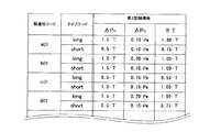
又、図7に示されるように、上記第2記録規格情報には、上記製造者コード及びタイプコードによる組み合わせと、その組み合わせ各々に最適な第2記録規格による波形パラメータ(ΔPD、ΔPH、θT)とが対応付けして記述されている。すなわち、各製造者毎の記録ディスク各々に対して最適な記録信号を生成することができる記録規格による波形パラメータ(ΔPD、ΔPH、θT)が登録されているのである。
【0019】
又、図8に示されるように、上記記第3記録規格情報には、上記タイプコード毎に、最適な第3記録規格による波形パラメータ(ΔPD、ΔPH、θT)が対応付けして記述されている。すなわち、記録ディスクがロングタイプである場合、並びに、ショートタイプである場合の夫々にて採用し得る記録規格による波形パラメータ(ΔPD、ΔPH、θT)が登録されているのである。
【0020】
更に、図4に示されるが如くROM34のプログラム領域には、情報信号記録再生装置自体の動作を司る為のソフトウェアが予め格納されている。
以下に、かかるソフトウェアに従ってシステム制御回路30が実施する情報信号記録再生装置の制御動作について説明する。
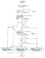
先ず、使用者が記録ディスク17に情報データを記録すべく操作装置31を操作すると、操作装置31は記録指令信号をシステム制御回路30に送出する。かかる記録指令信号に応じて、システム制御回路30は、上記ソフトウェアに基づくメイン制御フロー(説明せず)の実行を一時中断し、図9に示されるが如き記録初期設定サブルーチンの実行に移行する。
【0021】
図9において、先ず、システム制御回路30は、記録ディスク17の管理領域から記録情報の読み取りを行わせるべく、記録再生ヘッド14を移送させるスライダサーボ制御信号をサーボ回路18に供給すると共に、情報読取開始指令信号を記録再生ヘッド14に供給する(ステップS1)。これに応じて、記録再生ヘッド14は、記録ディスク17上における上記管理領域に移送され、ここから記録情報の読み取りを開始する。この際、復調回路19は、上記管理領域の読み取りに対応した再生情報データ信号RDをシステム制御回路30に送出する。
【0022】
次に、システム制御回路30は、かかる再生情報データ信号RD中からリードインスタートタイムを抽出し、これを内蔵レジスタT(図示せぬ)に記憶させる。更に、この再生情報データ信号RD中からメディアタイプ及びβカテゴリ情報の検索を行い、検索出来た場合には論理レベル"1"、出来なかった場合には論理レベル"0"のフラグを第1フラグレジスタFR1(図示せぬ)に書き込む。この際、上記メディアタイプ及びβカテゴリ情報を検索出来た場合には、システム制御回路30は、これらメディアタイプ及びβカテゴリ情報を内蔵レジスタY(図示せぬ)に記憶させる(ステップS2)。
【0023】
次に、システム制御回路30は、図5に示されるが如くROM34に登録されている製造者コード情報中から、上記内蔵レジスタTに記憶されているリードインスタートタイムに対応した製造者コード及びタイプコード各々を検索する。この際、このリードインスタートタイムに対応した製造者コード及びタイプコードを検索出来た場合には論理レベル"1"、出来なかった場合には論理レベル"0"のフラグを第2フラグレジスタFR2(図示せぬ)に書き込む。尚、製造者コード及びタイプコードを検索出来た場合には、システム制御回路30は、これら製造者コード及びタイプコード各々を内蔵レジスタZ(図示せぬ)に記憶させる(ステップS3)。
【0024】
次に、システム制御回路30は、上記第2フラグレジスタFR2の内容が論理レベル"1"であるか否か、すなわち、ROM34に登録されている製造者コード情報中に、記録ディスク17のリードインスタートタイムに対応した製造者コード及びタイプコードが存在するのか否かの判定を行う(ステップS4)。かかるステップS4において、上記第2フラグレジスタFR2の内容が論理レベル"1"、すなわち、ROM34に登録されている製造者コード情報中に、記録ディスク17のリードインスタートタイムに対応した製造者及びタイプコードが存在する場合、システム制御回路30は、次のステップS5を実施する。ステップS5では、システム制御回路30は、上記第1フラグレジスタFR1の内容が論理レベル"1"であるか否か、すなわち、図1に示されるが如きメディアタイプ及びβカテゴリ情報が記録ディスク17に記録されているか否かの判定を行う(ステップS5)。ステップS5において、上記第1フラグレジスタFR1の内容が論理レベル"1"、すなわち、メディアタイプ及びβカテゴリ情報が記録ディスク17に記録されていると判定された場合、システム制御回路30は、次のステップS6を実施する。かかるステップS6では、システム制御回路30は、図6に示されるが如くROM34に登録されている製造者別の専用ディスクタイプ情報中から、上記内蔵レジスタZに記憶されている製造者コード及びタイプコードに対応した専用ディスクタイプ(メディアタイプ+βカテゴリ)の検索を行う。この際、上記製造者コード及びタイプコードに対応した専用ディスクタイプを検索出来た場合には論理レベル"1"、出来なかった場合には論理レベル"0"のフラグを第3フラグレジスタFR3(図示せぬ)に書き込む。更に、上記専用ディスクタイプ(メディアタイプ+βカテゴリ)を検索出来た場合、システム制御回路30は、そのメディアタイプ及びβカテゴリ情報を内蔵レジスタX(図示せぬ)に記憶させる(ステップS6)。
【0025】
次に、システム制御回路30は、上記第3フラグレジスタFR3の内容が論理レベル"1"であるか否かの判定を行う(ステップS7)。すなわち、ステップS7では、図6に示されるが如くROM34に登録されている製造者別の専用ディスクタイプ情報中に、記録ディスク17の製造者コード及びタイプコードに対応した専用ディスクタイプ(メディアタイプ+βカテゴリ)が存在するか否かの判定を行うのである。かかるステップS7において、上記第3フラグレジスタFR3の内容が論理レベル"1"、すなわち、記録ディスク17の製造者コード及びタイプコードに対応した専用ディスクタイプ(メディアタイプ+βカテゴリ)が存在すると判定された場合、システム制御回路30は、次のステップS8を実施する。ステップS8において、システム制御回路30は、上記内蔵レジスタX及びY各々に記憶されている内容が互いに一致しているか否か、すなわち記録ディスク17に記録されていた共有ディスクタイプ(メディアタイプ+βカテゴリ)と、このROM34から読み出された専用ディスクタイプ(メディアタイプ+βカテゴリ)とが一致しているか否かの判定を行う(ステップS8)。かかるステップS8において、両者が一致していないと判定された場合、システム制御回路30は、図1に示されるが如くROM34に登録されている第1記録規格情報中から、上記内蔵レジスタYに記憶されている共有ディスクタイプ(メディアタイプ+βカテゴリ)に対応した第1記録規格による波形パラメータ(ΔPD、ΔPH、θT)を読み出し、これを上述した如き記録規格信号WSとして上記記録信号波形生成回路12に供給する(ステップS9)。かかるステップS9の実行に応じて、記録信号波形生成回路12は、記録ディスク17に記録されていた共有ディスクタイプ(メディアタイプ+βカテゴリ)に対応した第1記録規格による波形パラメータ(ΔPD、ΔPH、θT)に基づいた波形の記録信号を生成するように設定される。
【0026】
すなわち、記録ディスク17に記録されていた共有ディスクタイプと、ROM34から読み出された専用ディスクタイプとが異なる場合には、この記録ディスクが、上記第2記録規格を定めた時点では規格化されていなかった記録特性を有する記録ディスクであると判断する。そして、ROM34に登録されている第1記録規格情報中から、記録ディスク17に記録されていた共有ディスクタイプに対応した第1記録規格による波形パラメータ(ΔPD、ΔPH、θT)を読み出し、これにて記録信号波形生成回路12の設定を行うのである。
【0027】
一方、上記ステップS5、S7において上記第1フラグレジスタFR1又は第3フラグレジスタFR3の内容が論理レベル"1"ではないと判定された場合、又は、上記ステップS8において上記内蔵レジスタX及びYに記憶されている内容が互いに一致していると判定された場合、システム制御回路30は、以下のステップS10を実行する。ステップS10では、システム制御回路30は、図7に示されるが如くROM34に登録されている第2記録規格情報中から、上記内蔵レジスタZに記憶されている製造者コード及びタイプコードに対応した第2記録規格による波形パラメータ(ΔPD、ΔPH、θT)を読み出し、これを前述した如き記録規格信号WSとして上記記録信号波形生成回路12に供給する(ステップS10)。
【0028】
すなわち、以下の3つの条件a〜cのいずれかに該当する場合には、記録ディスクが、第2記録規格を定めた時点において規格化されていた記録特性を採用した記録ディスクであると判断する。そして、ROM34に登録記憶されている第2記録規格情報中から、記録ディスク17の製造者を示す製造者コード及びタイプコードに対応した第2記録規格による波形パラメータ(ΔPD、ΔPH、θT)を読み出し、これにて上記記録信号波形生成回路12の設定を行うのである。
【0029】
a.記録ディスク17にメディアタイプ情報及びβカテゴリ情報が記録さ れていない場合。
b.専用ディスクタイプがROM34に登録されていない場合。
c.記録ディスク17に記録されていた共有ディスクタイプと、ROM34から読み出された専用ディスクタイプとが一致している場合。
【0030】
又、上記ステップS4において、上記第2フラグレジスタFR2の内容が論理レベル"1"ではない、すなわちROM34に登録されている製造者コード情報中に、記録ディスク17のリードインスタートタイムに対応した製造者及びタイプコードが存在しない場合、システム制御回路30は、次のステップS11を実施する。ステップS11では、システム制御回路30は、上記第1フラグレジスタFR1の内容が論理レベル"1"であるか否か、すなわち、図1に示されるが如きメディアタイプ及びβカテゴリ情報が記録ディスク17に記録されているか否かの判定を行う(ステップS11)。かかるステップS11において、上記第1フラグレジスタFR1の内容が論理レベル"1"、つまり、メディアタイプ及びβカテゴリ情報が記録ディスク17に記録されていると判定された場合、システム制御回路30は、次に、上記ステップS9を実行する。一方、かかるステップS11において、上記第1フラグレジスタFR1の内容が論理レベル"1"ではない、つまり、メディアタイプ及びβカテゴリ情報が記録ディスク17に記録されていないと判定された場合、システム制御回路30は、次のステップ12を実行する。ステップS12において、システム制御回路30は、図8に示されるが如くROM34に登録されている第3記録規格情報中から、上記内蔵レジスタZに記憶されているタイプコードに対応した第3記録規格による波形パラメータ(ΔPD、ΔPH、θT)を読み出し、これを前述した如き記録規格信号WSとして上記記録信号波形生成回路12に供給する(ステップS12)。
【0031】
すなわち、記録ディスク17の製造者を示す製造者コード及びタイプコードがROM34に登録されていない場合には、ROM34に登録されている第1記録規格情報中から、記録ディスク17に記録されていた共有ディスクタイプ(メディアタイプ+βカテゴリ)に対応した第1記録規格による波形パラメータ(ΔPD、ΔPH、θT)を読み出し、これにて記録信号波形生成回路12の設定を行う。この際、記録ディスク17にメディアタイプ及びβカテゴリが記録されていなかった場合には、記録ディスク17のリードインスタートタイムに対応したタイプコードを用いて、ROM34に登録されている第3記録規格情報中から第3記録規格による波形パラメータ(ΔPD、ΔPH、θT)を読み出し、これにて記録信号波形生成回路12の設定を行うのである。
【0032】
上記ステップS9、S10、S12のいずれかが終了したら、システム制御回路30は、この記録動作初期設定サブルーチンを抜けてメイン制御フローの実行に戻る。
以上の如く、かかる情報記録再生装置においては、記録ディスク17に記録されている共有ディスクタイプ(メディアタイプ+βカテゴリ)と、ROM34から読み出された専用ディスクタイプとが異なる場合には、記録ディスク17に記録されている共有ディスクタイプに対応した第1記録規格による波形パラメータ(ΔPD、ΔPH、θT)に基づいて記録信号の波形を生成する(ステップS9)。
【0033】
一方、上記共有ディスクタイプと、専用ディスクタイプとが同一である場合には、記録ディスク17の製造者コードとタイプコードとの組み合わせ毎に登録してある第2記録規格による波形パラメータ(ΔPD、ΔPH、θT)に基づいて記録信号の波形を生成する(ステップS10)。
更に、記録ディスク17にメディアタイプ及びβカテゴリ情報が記録されておらず、かつ記録ディスク17の製造者コード及びタイプコードがROM34に登録されていない場合には、記録ディスク17のタイプコードに対応した第3記録規格による波形パラメータ(ΔPD、ΔPH、θT)に基づいて記録信号の波形を生成する(ステップS12)ようにしている。
【0034】
上述したように、共有ディスクタイプ情報に対応してROMから読み出される第1記録規格情報は6種類しかないが、リードインスタートタイムを使用したディスク製造者の特定はさらに細かくされており、それに対応して読み出される第2記録規格情報は100種類以上にわたり存在する。しかしながら、リードインスタートタイムは単にディスク製造者を特定しているだけなので、後にディスク製造者が記録ディスクの記録特性を変えると、第2記録規格情報が適切でなくなる問題がある。
【0035】
これに対し、上述した実施例によれば、ディスクに記録された共有ディスクタイプ情報とROMから読み出された専用ディスクタイプ情報を比較することにより、ディスク製造者が記録ディスクの記録特性を変えたか否かを判断する。この際、もし、両ディスクタイプ情報が一致しない場合にはディスク製造者が記録ディスクの記録特性を変えた可能性があると判断して、第1記録規格情報を選択し、必要最小限の品質の情報記録を確保する。一方、両ディスクタイプ情報が一致する場合には第2記録規格情報を定めた時点の同一の記録特性を持つディスクであると判断し、より細かくディスク種類毎に設定されている第2記録規格情報を選択し、高精度の情報記録を行う。
【0036】
尚、本発明は上述した実施例に限定されるものではない。
例えば、上述した実施例によれば、ROM34にリードインスタートタイムに対応した製造者コードとタイプコード(図5)、この製造者コードとタイプコードに対応した専用ディスクタイプ(図6)、及び製造者コードとタイプコードに対応した第2記録規格による波形パラメータ(図7)を記憶するようにしている。しかしながら、ROM34にリードインスタートタイムに対応した共有ディスクタイプと、第2記録規格情報とを記憶し、製造者コードおよびタイプコードを介在させなくても良い。
【0037】
又、上記実施例においては、記録ディスクに記録されているリードインスタートタイムに基づいて、上記ROM34から第2記録規格情報を読み出すようにしたが、かかる構成に限定されるものではない。要するに、ディスク製造者、あるいは専用ディスクタイプを示す所定情報を記録ディスクから読み出し、この所定情報に対応した第2記録規格情報を上記ROM34から読み出すような構成であれば良いのである。
【0038】
又、各記録規格情報や製造者コードを記憶する記憶手段として一つのROMを用いたが、複数のROMを用いたり、ハードディスク等の他の記憶手段を用いることができるのは勿論である。
又、記録ディスクに記録された共有ディスクタイプ情報Xと、ROMから読み出された専用ディスクタイプ情報Yとの一致を見て、記録ディスクが第2記録規格を定めた時点と同一の記録特性を持つ記録ディスクであるか否かを判断するようにしたが、その手法に限定されるものでもない。例えば、記録ディスクに記録された他の情報、例えばディスク製造日やバージョン情報を記録し、それら情報に基づき判断することもできる。また、第2記録規格情報に従った記録信号により記録し、その再生信号の性能を見て、例えばジッター値が所定値よりも大きければ、異なる記録特性を持つ記録特性であると判断することもできる。
【0039】
【発明の効果】
以上、詳述した如く、本発明による情報記録再生装置においては、先ず、装着された記録ディスクが第2の記録規格を定めた時点において規格化されている記録特性を有する記録ディスクであるか否かを判断する。この際、第2の記録規格を定めた時点において規格化されていない記録特性を有するものであると判断した場合には第1記録規格に基づいて記録信号の波形を生成する。従って、万が一に記録ディスクの記録特性が大きく変化している場合にもその影響を受けることなく、必要最小限の品質で情報記録が可能となる。一方、上記第2の記録規格を定めた時点において規格化されている記録特性を有する記録ディスクであると判断した場合には、上記第1記録規格よりも極め細かくディスク種類毎に設定された上記第2の記録規格に基づいて記録信号の波形を生成する。従って、非常に高精度の情報記録が可能となる。
【0040】
よって、本発明による情報記録再生装置によれば、より精度の高い情報記録が可能となるのである。
【図面の簡単な説明】
【図1】記録ディスクのメディアタイプ及びβカテゴリと、第1記録規格による波形パラメータ(ΔPD、ΔPH、θT)とが対応づけされている第1記録規格情報の一例を示す図である。
【図2】記録規格による波形パラメータ(ΔPD、ΔPH、θT)に基づく記録信号の波形を示す図である。
【図3】本発明による情報記録再生装置の構成を示す図である。
【図4】ROM34の概略メモリマップを示す図である。
【図5】ROM34に記憶されている製造者コード情報の一例を示す図である。
【図6】ROM34に記憶されている専用ディスクタイプ情報の一例を示す図である。
【図7】ROM34に記憶されている第2記録規格情報の一例を示す図である。
【図8】ROM34に記憶されている第3記録規格情報の一例を示す図である。
【図9】本発明の情報記録方法に基づく記録初期設定サブルーチンを示す図である。
【主要部分の符号の説明】
12 記録信号波形生成回路
14 記録再生ヘッド
17 記録ディスク
30 システム制御回路
34 ROM[0001]
BACKGROUND OF THE INVENTION
The present invention relates to an information recording / reproducing apparatus for recording information data on a recording medium.
[0002]
[Background]
At present, recording disks such as write-once CD (Compact Disc) -R, DVD (Digital Versatile Disc) -R, and rewritable DVD-RW are attracting attention as optical recording media on which information data can be written. ing.
The information recording apparatus performs the following processing, for example, when writing information data to the recording disk.
[0003]
First, a recording signal having a level change corresponding to information data is generated and supplied to a writing laser diode. The writing laser diode generates a laser beam having an optical power corresponding to the level of the recording signal, and irradiates the laser beam on the recording surface of the recording disk. At this time, the region irradiated with the laser beam has a lower reflectance than the region not irradiated, and the region with the lowered reflectance becomes a recording pit that carries information data.
[0004]
However, the shape of the recording pit formed by the laser beam irradiation varies depending on the structure and material of the recording disk.
Therefore, in the CD-R standard which is a write-once type recording disk, so-called Orange Book, the CD-R is classified into a media type (types A to C) and a β category (high, low) as shown in FIG. Are classified into six types of disk types (hereinafter referred to as shared disk types) based on the combination of the above, and are prescribed to be adopted by each manufacturer.
[0005]
For example, a CD-R manufacturer first records information data on a CD-R manufactured by the company using a standard recording device capable of recording information on any of the above six types of CD-Rs. Then, based on the recording result, it is determined which of the above six shared disk types corresponds to this CD-R. The manufacturer of the CD-R records the shared disk type (media type + β category) obtained by the determination result on the CD-R and ships it.
[0006]
On the other hand, on the recording apparatus side that records information data on the shipped CD-R, in order to generate optimum recording signals as shown in FIG. 1 for each of the six types of shared disk types. Waveform parameter (ΔP) according to the first recording standard D , ΔP H , ΘT) is set. According to the first recording standard, a 3T-EFM (Eight to Fourteen Modulation) modulation signal carrying an information data signal, for example, as shown in FIG. 2 (a), has a waveform as shown in FIG. 2 (b). Converted into a recording signal. As shown in FIG. 2B, the recording signal waveform first rises with a delay of time θT from the rise of the EFM modulation signal. And ΔP D Recording power P over a period of W ΔP H Recording power P until the fall of the EFM modulation signal. W Is kept at the level of In other words, the recording device reads the shared disk type from the loaded CD-R, generates a recording signal having a waveform according to the recording standard corresponding to the shared disk type, and drives the writing laser diode. By doing so, formation of recording pits having a good shape is realized.
[0007]
In other words, Orange Book prompts the manufacturer to manufacture a CD-R corresponding to one of the above six types of shared disk types.
[0008]
[Problems to be solved by the invention]
However, some manufacturers of CD-R manufacture CD-Rs that make the manufactured CD-R correspond to the above six types of shared disk types, but this shared disk type is not necessarily the best. There is a case.
[0009]
[Means for Solving the Problems]
The present invention has been made to solve such a problem, and an object thereof is to provide an information recording / reproducing apparatus and an information recording method capable of forming a recording pit having a better shape.
The information recording / reproducing apparatus according to
[0010]
or,
First recording standard information in which shared disk types indicating various disk types of the recording disk are associated with waveform parameters of the first recording standard when the recording signal is generated, and each recording disk manufacturer Second recording standard information in which a manufacturer code and a type code indicating reactivity of pit formation and a waveform parameter of a second recording standard at the time of generating the recording signal are associated with each other, and each of the manufacturer codes The first recording standard information, the second recording standard information, and the manufacturer code information are stored in storage means for storing manufacturer code information associated with a lead-in start time and a type code, respectively. A process of reading the shared disk type and the lead-in start time recorded on the recording disk, respectively, The manufacturer code corresponding to the lead-in start time read from the recording disc is searched from the manufacturer code information, and the searched manufacturer code and the shared disc type read from the recording disc And a step of selecting one of the waveform parameters from each of the first recording standard information and the second recording standard information and generating the recording signal based on the waveform parameters. .
[0011]
DETAILED DESCRIPTION OF THE INVENTION
FIG. 3 is a diagram showing a configuration of an information recording / reproducing apparatus according to the present invention.
In FIG. 3, a
[0012]
The
[0013]
A laser diode (not shown) mounted on the recording / reproducing head 14 has an optical power corresponding to the level change of the recording signal RM in response to the information recording start command signal supplied from the
[0014]
The
Connected to the
[0015]
FIG. 4 is a schematic memory map of the
As shown in FIG. 4, the
[0016]
As shown in FIG. 5, in the manufacturer code information, the lead-in start time indicating the reading start position on the recording disk is described in association with the manufacturer code and the type code indicating each manufacturer. It is. The type code indicates disc type information obtained by dividing a recording disc into two types of disc types according to the recording characteristics. These two disc types are a long type that requires a long recording signal waveform due to poor pit formation response to the recording beam, and a short type that requires a short recording signal waveform due to good pit formation response to the recording beam. There is.
[0017]
Further, as shown in FIG. 6, in the dedicated disc type information, a combination of the manufacturer code and the type code is described in association with various disc types (media type + β category). . That is, the shared disk type information recorded on the recording disk by the recording disk manufacturer at the time when the second recording standard information is determined is registered as the dedicated disk type information.
[0018]
As shown in FIG. 1, the first recording standard information includes six types of shared disk types defined by the Orange Book and waveform parameters (ΔP according to the first recording standard). D , ΔP H , ΘT) are described in association with each other.
As shown in FIG. 7, the second recording standard information includes a combination of the manufacturer code and type code, and a waveform parameter (ΔP based on the second recording standard optimum for each combination). D , ΔP H , ΘT) are described in association with each other. That is, the waveform parameter (ΔP) according to the recording standard capable of generating an optimum recording signal for each recording disk for each manufacturer. D , ΔP H , ΘT) is registered.
[0019]
As shown in FIG. 8, the third recording standard information includes a waveform parameter (ΔP) according to the optimum third recording standard for each type code. D , ΔP H , ΘT) are described in association with each other. That is, the waveform parameter (ΔP) according to the recording standard that can be adopted when the recording disk is a long type and when it is a short type. D , ΔP H , ΘT) is registered.
[0020]
Further, as shown in FIG. 4, in the program area of the
The control operation of the information signal recording / reproducing apparatus performed by the
First, when the user operates the operating
[0021]
In FIG. 9, first, the
[0022]
Next, the
[0023]
Next, as shown in FIG. 5, the
[0024]
Next, the
[0025]
Next, the
[0026]
That is, when the shared disk type recorded on the
[0027]
On the other hand, in the steps S5 and S7, the first flag register FR 1 Or the third flag register FR Three When it is determined that the content of the memory is not at the logic level “1”, or when it is determined in step S8 that the contents stored in the built-in registers X and Y match each other, the
[0028]
That is, if any of the following three conditions a to c is satisfied, it is determined that the recording disk is a recording disk that employs the recording characteristics that have been standardized when the second recording standard is established. . Then, from the second recording standard information registered and stored in the
[0029]
a. When media type information and β category information are not recorded on the
b. The dedicated disk type is not registered in the
c. The shared disk type recorded on the
[0030]
In step S4, the second flag register FR 2 Is not the logical level “1”, that is, the lead-in start type of the
[0031]
In other words, when the manufacturer code and the type code indicating the manufacturer of the
[0032]
When any of the above steps S9, S10, and S12 is completed, the
As described above, in such an information recording / reproducing apparatus, when the shared disk type (media type + β category) recorded on the
[0033]
On the other hand, when the shared disk type and the dedicated disk type are the same, the waveform parameter (ΔP) according to the second recording standard registered for each combination of the manufacturer code and the type code of the
Further, when the media type and β category information are not recorded on the
[0034]
As described above, there are only six types of the first recording standard information read from the ROM corresponding to the shared disk type information, but the specification of the disk manufacturer using the lead-in start time has been further refined. Thus, there are over 100 types of second recording standard information read out. However, since the lead-in start time merely identifies the disc manufacturer, there is a problem that the second recording standard information becomes inappropriate when the disc manufacturer later changes the recording characteristics of the recording disc.
[0035]
On the other hand, according to the above-described embodiment, the disc manufacturer changed the recording characteristics of the recording disc by comparing the shared disc type information recorded on the disc with the dedicated disc type information read from the ROM. Judge whether or not. At this time, if the disc type information does not match, it is determined that the disc manufacturer may have changed the recording characteristics of the recording disc, the first recording standard information is selected, and the minimum quality required. Secure information records. On the other hand, if both disc type information matches, it is determined that the disc has the same recording characteristics at the time when the second recording standard information was determined, and the second recording standard information set for each disc type more finely. To record information with high accuracy.
[0036]
In addition, this invention is not limited to the Example mentioned above.
For example, according to the above-described embodiment, the manufacturer code and type code (FIG. 5) corresponding to the lead-in start time in the
[0037]
In the above embodiment, the second recording standard information is read from the
[0038]
Further, although one ROM is used as a storage means for storing each recording standard information and manufacturer code, it goes without saying that a plurality of ROMs or other storage means such as a hard disk can be used.
In addition, by looking at the coincidence between the shared disk type information X recorded on the recording disk and the dedicated disk type information Y read from the ROM, the same recording characteristics as when the recording disk defined the second recording standard were obtained. Although it is determined whether or not the recording disk is possessed, it is not limited to this method. For example, other information recorded on the recording disk, for example, disk manufacturing date and version information can be recorded, and judgment can be made based on the information. In addition, recording is performed with a recording signal in accordance with the second recording standard information, and the performance of the reproduced signal is determined. For example, if the jitter value is larger than a predetermined value, it can be determined that the recording characteristic has different recording characteristics. it can.
[0039]
【The invention's effect】
As described above in detail, in the information recording / reproducing apparatus according to the present invention, first, whether or not the mounted recording disk is a recording disk having recording characteristics standardized at the time when the second recording standard is determined. Determine whether. At this time, if it is determined that the recording characteristic is not standardized at the time when the second recording standard is determined, the waveform of the recording signal is generated based on the first recording standard. Therefore, even if the recording characteristics of the recording disk are greatly changed, it is possible to record information with the minimum necessary quality without being affected by the change. On the other hand, when it is determined that the recording disk has the recording characteristics standardized at the time when the second recording standard is determined, the above-mentioned setting is made finer for each disk type than the first recording standard. A waveform of a recording signal is generated based on the second recording standard. Therefore, it is possible to record information with very high accuracy.
[0040]
Therefore, according to the information recording / reproducing apparatus of the present invention, it is possible to record information with higher accuracy.
[Brief description of the drawings]
FIG. 1 shows a recording disk media type and β category, and waveform parameters (ΔP D , ΔP H , ΘT) is a diagram showing an example of the first recording standard information associated with each other.
FIG. 2 shows waveform parameters (ΔP D , ΔP H , ΘT) is a diagram illustrating a waveform of a recording signal.
FIG. 3 is a diagram showing a configuration of an information recording / reproducing apparatus according to the present invention.
4 is a schematic memory map of a
5 is a diagram showing an example of manufacturer code information stored in a
6 is a diagram showing an example of dedicated disk type information stored in a
7 is a diagram showing an example of second recording standard information stored in a
8 is a diagram illustrating an example of third recording standard information stored in a
FIG. 9 is a diagram showing a recording initial setting subroutine based on the information recording method of the present invention.
[Explanation of main part codes]
12 Recording signal waveform generation circuit
14 Recording / playback head
17 Recording disc
30 System control circuit
34 ROM
Claims (8)
記録ディスクの各種のディスクタイプを示す共有ディスクタイプと前記記録信号を生成する際の第1記録規格の波形パラメータとが対応付けされている第1記録規格情報と、記録ディスクの各製造者を示す製造者コード及びピット形成の反応性を示すタイプコードと前記記録信号を生成する際の第2記録規格の波形パラメータとが対応付けされている第2記録規格情報と、が記憶されている記憶手段と、
前記記録ディスクに記録されている共有ディスクタイプ及びリードインスタートタイムを夫々読み取る手段と、
前記記録ディスクから読み取られた共有ディスクタイプ及びリードインスタートタイムに基づいて、前記第1記録規格情報及び前記第2記録規格情報から前記波形パラメータの1つを選択し、この波形パラメータに基づいて前記記録信号の生成を行う記録信号生成手段と、を有することを特徴とする情報記録再生装置号に応じた記録ビーム光を記録ディスクに照射することにより前記記録ディスクに対して情報記録を行なう情報記録再生装置であって、
記録ディスクの各種のディスクタイプを示す共有ディスクタイプと前記記録信号を生成する際の第1記録規格の波形パラメータとが対応付けされている第1記録規格情報と、記録ディスクの各製造者を示す製造者コード及びピット形成の反応性を示すタイプコードと前記記録信号を生成する際の第2記録規格の波形パラメータとが対応付けされている第2記録規格情報と、が記憶されている記憶手段と、
前記記録ディスクに記録されている共有ディスクタイプ及びリードインスタートタイムを夫々読み取る手段と、
前記記録ディスクから読み取られた共有ディスクタイプ及びリードインスタートタイムに基づいて、前記第1記録規格情報及び前記第2記録規格情報から前記波形パラメータの1つを選択し、この波形パラメータに基づいて前記記録信号の生成を行う記録信号生成手段と、を有することを特徴とする情報記録再生装置。An information recording / reproducing apparatus for recording information on the recording disk by irradiating the recording disk with a recording beam light corresponding to a recording signal bearing information data,
A first recording standard information shared disk type showing various disc types of record disc and the waveform parameters of the first recording standard when generating the recording signal is associated, the production of record disc A manufacturer code indicating the manufacturer, a type code indicating the pit formation reactivity, and second recording standard information in which the waveform parameters of the second recording standard used when generating the recording signal are associated with each other . Storage means
And means for reading each of the shared disk type及 beauty lead-in start time that is recorded on the recording disk,
On the basis of the recording disk on the shared disk type及 beauty lead-in start time that has been read, and selecting one of said waveform parameter from said first recording standard information and the second recording standard information, based on the waveform parameters And recording signal generation means for generating the recording signal, and recording information on the recording disk by irradiating the recording disk with a recording beam light according to the information recording / reproducing apparatus number An information recording / reproducing apparatus,
A first recording standard information shared disk type showing various disc types of record disc and the waveform parameters of the first recording standard when generating the recording signal is associated, the production of record disc A manufacturer code indicating the manufacturer, a type code indicating the pit formation reactivity, and second recording standard information in which the waveform parameters of the second recording standard used when generating the recording signal are associated with each other . Storage means
And means for reading each of the shared disk type及 beauty lead-in start time that is recorded on the recording disk,
On the basis of the recording disk on the shared disk type及 beauty lead-in start time that has been read, and selecting one of said waveform parameter from said first recording standard information and the second recording standard information, based on the waveform parameters And a recording signal generating means for generating the recording signal.
記録ディスクの各種のディスクタイプを示す共有ディスクタイプと前記記録信号を生成する際の第1記録規格の波形パラメータとが対応付けされている第1記録規格情報と、記録ディスクの各製造者を示す製造者コード及びピット形成の反応性を示すタイプコードと前記記録信号を生成する際の第2記録規格の波形パラメータとが対応付けされている第2記録規格情報と、前記製造者コードの各々とリードインスタートタイム及びタイプコードとが夫々対応付けされている製造者コード情報と、が夫々記憶されている記憶手段と、
前記記録ディスクに記録されている共有ディスクタイプ及びリードインスタートタイムを夫々読み取る手段と、
前記記録ディスクから読み取られた前記リードインスタートタイムに対応した前記製造者コードを前記製造者コード情報から検索し、この検索された前記製造者コードと前記記録ディスクから読み取られた前記共有ディスクタイプとに基づいて、前記第1記録規格情報及び前記第2記録規格情報各々の内から前記波形パラメータの1つを選択しこの波形パラメータに基づいて前記記録信号の生成を行う記録信号生成手段と、を有することを特徴とする情報記録再生装置。 An information recording / reproducing apparatus for recording information on the recording disk by irradiating the recording disk with a recording beam light corresponding to a recording signal bearing information data,
First recording standard information in which shared disk types indicating various disk types of the recording disk are associated with waveform parameters of the first recording standard when the recording signal is generated, and each recording disk manufacturer Second recording standard information in which a manufacturer code and a type code indicating reactivity of pit formation and a waveform parameter of a second recording standard at the time of generating the recording signal are associated with each other, and each of the manufacturer codes Manufacturer code information in which the lead-in start time and the type code are associated with each other;
Means for respectively reading the shared disk type and the lead-in start time recorded on the recording disk;
The manufacturer code corresponding to the lead-in start time read from the recording disk is searched from the manufacturer code information, the searched manufacturer code and the shared disk type read from the recording disk, A recording signal generating means for selecting one of the waveform parameters from each of the first recording standard information and the second recording standard information and generating the recording signal based on the waveform parameters; information recording and reproducing apparatus, comprising.
前記記録信号生成手段は、前記記録ディスクから読み取られた前記リードインスタートタイムに対応した前記ディスクタイプを前記専用ディスクタイプ情報中から検索し、この検索された前記ディスクタイプと前記記録ディスクから読み出された前記共有ディスクタイプとが互いに同一である場合には前記第2記録規格の前記波形パラメータに基づいて前記記録信号の生成を行う一方、前記検索された前記ディスクタイプと前記記録ディスクから読み出された前記共有ディスクタイプとが互いに異なる場合には前記第1記録規格の前記波形パラメータに基づいて前記記録信号の生成を行うことを特徴とする請求項2記載の情報記録再生装置。Furthermore in the storage means, various disk types of recording disks, only disc type information, each type code and manufacturer code is associated is stored,
The recording signal generation means searches the dedicated disk type information for the disk type corresponding to the lead-in start time read from the recording disk, and reads from the searched disk type and the recording disk. If the shared disk type is identical to each other, the recording signal is generated based on the waveform parameters of the second recording standard, while the retrieved disk type and the recording disk are read out. 3. The information recording / reproducing apparatus according to claim 2 , wherein when the shared disk type is different from each other, the recording signal is generated based on the waveform parameter of the first recording standard .
記録ディスクの各種のディスクタイプを示す共有ディスクタイプと前記記録信号を生成する際の第1記録規格の波形パラメータとが対応付けされている第1記録規格情報と、記録ディスクの各製造者を示す製造者コード及びピット形成の反応性を示すタイプコードと前記記録信号を生成する際の第2記録規格の波形パラメータとが対応付けされている第2記録規格情報と、前記製造者コードの各々とリードインスタートタイム及びタイプコードとが夫々対応付けされている製造者コード情報と、が夫々記憶されている記憶手段から、前記第1記録規格情報、前記第2記録規格情報及び前記製造者コード情報を読み出す行程と、
前記記録ディスクに記録されている共有ディスクタイプ及びリードインスタートタイムを夫々読み取る行程と、
前記記録ディスクから読み取られた前記リードインスタートタイムに対応した前記製造者コードを前記製造者コード情報から検索し、この検索された前記製造者コードと前記記録ディスクから読み取られた前記共有ディスクタイプとに基づいて、前記第1記録規格情報及び前記第2記録規格情報各々の内から前記波形パラメータの1つを選択しこの波形パラメータに基づいて前記記録信号の生成を行う行程と、を有することを特徴とする情報記録方法。 An information recording method for performing information recording on the recording disk by irradiating the recording disk with a recording beam light corresponding to a recording signal bearing information data,
First recording standard information in which shared disk types indicating various disk types of the recording disk are associated with waveform parameters of the first recording standard when the recording signal is generated, and each recording disk manufacturer Second recording standard information in which a manufacturer code and a type code indicating reactivity of pit formation and a waveform parameter of a second recording standard at the time of generating the recording signal are associated with each other, and each of the manufacturer codes The first recording standard information, the second recording standard information, and the manufacturer code information are stored in storage means for storing manufacturer code information associated with a lead-in start time and a type code, respectively. The process of reading
A process of reading each of the shared disk type and the lead-in start time recorded on the recording disk;
The manufacturer code corresponding to the lead-in start time read from the recording disk is searched from the manufacturer code information, the searched manufacturer code and the shared disk type read from the recording disk, A step of selecting one of the waveform parameters from each of the first recording standard information and the second recording standard information and generating the recording signal based on the waveform parameters. A characteristic information recording method.
Priority Applications (3)
| Application Number | Priority Date | Filing Date | Title |
|---|---|---|---|
| JP36421599A JP4097867B2 (en) | 1999-12-22 | 1999-12-22 | Information recording / reproducing apparatus and information recording method |
| EP00122873A EP1111596A3 (en) | 1999-12-22 | 2000-10-20 | Information recording/reproducing apparatus and information recording method |
| US09/695,424 US6381202B1 (en) | 1999-12-22 | 2000-10-25 | Information recording/reproducing apparatus and information recording method |
Applications Claiming Priority (1)
| Application Number | Priority Date | Filing Date | Title |
|---|---|---|---|
| JP36421599A JP4097867B2 (en) | 1999-12-22 | 1999-12-22 | Information recording / reproducing apparatus and information recording method |
Publications (2)
| Publication Number | Publication Date |
|---|---|
| JP2001184640A JP2001184640A (en) | 2001-07-06 |
| JP4097867B2 true JP4097867B2 (en) | 2008-06-11 |
Family
ID=18481267
Family Applications (1)
| Application Number | Title | Priority Date | Filing Date |
|---|---|---|---|
| JP36421599A Expired - Lifetime JP4097867B2 (en) | 1999-12-22 | 1999-12-22 | Information recording / reproducing apparatus and information recording method |
Country Status (3)
| Country | Link |
|---|---|
| US (1) | US6381202B1 (en) |
| EP (1) | EP1111596A3 (en) |
| JP (1) | JP4097867B2 (en) |
Families Citing this family (20)
| Publication number | Priority date | Publication date | Assignee | Title |
|---|---|---|---|---|
| TW517230B (en) | 2000-10-06 | 2003-01-11 | Pioneer Corp | Information recording and reproducing apparatus, information reproducing method, recording medium, information recording medium in which recording control program is stored, information recording and reproducing control program |
| JP2002245625A (en) * | 2001-02-19 | 2002-08-30 | Pioneer Electronic Corp | Recording medium, information recording device and method, information recording medium and recording program |
| JP2003022536A (en) * | 2001-07-03 | 2003-01-24 | Tdk Corp | Optical disk playing-back method and optical disk player |
| TWI260603B (en) * | 2001-09-29 | 2006-08-21 | Samsung Electronics Co Ltd | Method for recording data on optical recording medium |
| US7525890B2 (en) | 2001-09-29 | 2009-04-28 | Samsung Electronics Co., Ltd. | Method of and apparatus for recording data on optical recording medium |
| JP2004362631A (en) * | 2003-06-02 | 2004-12-24 | Ricoh Co Ltd | Information-recording device, information-recording device control software, information-recording device control unit, recording medium, and information-recording method |
| TWI250759B (en) * | 2003-06-09 | 2006-03-01 | Sony Corp | Information recording medium, data processing method and computer program |
| US7423943B2 (en) * | 2003-10-18 | 2008-09-09 | Dell Products L.P. | Method and system for setting optical drive write speed |
| KR100546400B1 (en) * | 2003-12-16 | 2006-01-26 | 삼성전자주식회사 | Method for determinating optimal recording velocity of optical disc |
| DE602005027756D1 (en) | 2004-03-31 | 2011-06-09 | Pioneer Corp | Recording pulse generating device and information recording device |
| KR20070049164A (en) * | 2004-09-13 | 2007-05-10 | 엘지전자 주식회사 | Method and apparatus for reproducing data from recording medium using local storage |
| US20060077817A1 (en) * | 2004-09-13 | 2006-04-13 | Seo Kang S | Method and apparatus for reproducing data from recording medium using local storage |
| KR101043375B1 (en) * | 2004-09-24 | 2011-06-22 | 삼성전자주식회사 | Optical disk recording apparatus and metod thereof |
| KR20060047549A (en) * | 2004-10-12 | 2006-05-18 | 엘지전자 주식회사 | Method and apparatus for reproducing a data recorded in recording medium using a local storage |
| EP1851765A1 (en) | 2004-10-18 | 2007-11-07 | Koninklijke Philips Electronics N.V. | Device and method for providing media-related parameters on a medium and for retrieving such parameters |
| KR20060063601A (en) * | 2004-12-03 | 2006-06-12 | 엘지전자 주식회사 | Method and apparatus of downloading/updating a data to local storage |
| CN101057286B (en) * | 2004-11-08 | 2010-04-07 | Lg电子株式会社 | Method and apparatus for reproducing a data recorded in recording medium using a local storage |
| KR20060081323A (en) * | 2005-01-07 | 2006-07-12 | 엘지전자 주식회사 | Method and apparatus for reproducing a data recorded in recording medium using a local storage |
| KR100694113B1 (en) * | 2005-05-24 | 2007-03-12 | 삼성전자주식회사 | Method for discriminating optical medium type, optical medium system and recording medium thereof |
| EP1946311A2 (en) * | 2005-10-31 | 2008-07-23 | Koninklijke Philips Electronics N.V. | Recording apparatus and recording method |
Family Cites Families (7)
| Publication number | Priority date | Publication date | Assignee | Title |
|---|---|---|---|---|
| JP2773898B2 (en) * | 1989-05-23 | 1998-07-09 | オリンパス光学工業株式会社 | Optical information recording / reproducing device |
| EP0549488B1 (en) * | 1991-12-20 | 1998-09-30 | Eastman Kodak Company | A storage media for an optical information system having an identification code embedded therein |
| US5502702A (en) * | 1993-08-09 | 1996-03-26 | Yamaha Corporation | Optical disc recording device using basic recording information and projection time control |
| CN1110038C (en) * | 1995-01-31 | 2003-05-28 | 索尼公司 | Device for reproducing optical recording medium |
| US5959280A (en) * | 1997-01-16 | 1999-09-28 | Laser Dynamics, Inc. | Multi-standard optical disk reading apparatus and method of reading using same |
| KR100272097B1 (en) * | 1997-07-16 | 2000-11-15 | 윤종용 | Method for adjusting the sled moving time according to a deck deflection as initializing optical disk reproducing apparatus |
| KR100255191B1 (en) * | 1997-12-31 | 2000-06-01 | 윤종용 | Disc and method for detecting kind of the disc in optical disc player |
-
1999
- 1999-12-22 JP JP36421599A patent/JP4097867B2/en not_active Expired - Lifetime
-
2000
- 2000-10-20 EP EP00122873A patent/EP1111596A3/en not_active Withdrawn
- 2000-10-25 US US09/695,424 patent/US6381202B1/en not_active Expired - Fee Related
Also Published As
| Publication number | Publication date |
|---|---|
| EP1111596A3 (en) | 2003-01-29 |
| EP1111596A2 (en) | 2001-06-27 |
| JP2001184640A (en) | 2001-07-06 |
| US6381202B1 (en) | 2002-04-30 |
Similar Documents
| Publication | Publication Date | Title |
|---|---|---|
| JP4097867B2 (en) | Information recording / reproducing apparatus and information recording method | |
| US7352684B2 (en) | Information medium and information recording and reproducing device | |
| JP3413680B2 (en) | Write-once optical disc apparatus and area boundary search method for write-once optical disc | |
| US20050185537A1 (en) | Evaluation method, recording method, program and recording medium, and optical disk apparatus | |
| JPH0773471A (en) | Information recorder for draw type optical disk | |
| US6614736B2 (en) | Optical disc drive, and recording/reproducing method | |
| JP2001250235A (en) | Optical information recording medium and recorder | |
| JP2003030844A (en) | Optical disk information recorder and optical disk | |
| JPH0773470A (en) | Draw type optical disk and its recorder | |
| JP2003257026A (en) | Optical information recording medium | |
| JP2001250324A (en) | Device and method for recording | |
| JP2537552B2 (en) | Optical disc player | |
| KR20020006427A (en) | Recording apparatus, recording medium, reproducing apparatus and discriminating method of recording medium | |
| JP3254120B2 (en) | Optical disk drive | |
| JP4025252B2 (en) | Information recording apparatus and information recording method | |
| JP2005190591A (en) | Optical disk device, its control method and recording medium | |
| JP2000348347A (en) | Optical disk | |
| US20030165101A1 (en) | Optical information recording medium | |
| US20040179450A1 (en) | Optical disc reproduction method and optical disc reproduction apparatus | |
| JP3693742B2 (en) | Information recording medium | |
| US20060018635A1 (en) | Optical disk, optical disk drive, and optical disk recording method | |
| JP4029964B2 (en) | Information recording control program, recording medium, and information recording apparatus | |
| US7440376B2 (en) | Operation condition setting system | |
| JP2004246956A (en) | Optical disk unit and recording condition setting method | |
| US20080130438A1 (en) | Optical disk apparatus and control method therefor |
Legal Events
| Date | Code | Title | Description |
|---|---|---|---|
| A621 | Written request for application examination |
Free format text: JAPANESE INTERMEDIATE CODE: A621 Effective date: 20050405 |
|
| A977 | Report on retrieval |
Free format text: JAPANESE INTERMEDIATE CODE: A971007 Effective date: 20070423 |
|
| A131 | Notification of reasons for refusal |
Free format text: JAPANESE INTERMEDIATE CODE: A131 Effective date: 20070911 |
|
| A521 | Written amendment |
Free format text: JAPANESE INTERMEDIATE CODE: A523 Effective date: 20071112 |
|
| TRDD | Decision of grant or rejection written | ||
| A01 | Written decision to grant a patent or to grant a registration (utility model) |
Free format text: JAPANESE INTERMEDIATE CODE: A01 Effective date: 20080311 |
|
| A61 | First payment of annual fees (during grant procedure) |
Free format text: JAPANESE INTERMEDIATE CODE: A61 Effective date: 20080312 |
|
| R150 | Certificate of patent or registration of utility model |
Free format text: JAPANESE INTERMEDIATE CODE: R150 |
|
| FPAY | Renewal fee payment (event date is renewal date of database) |
Free format text: PAYMENT UNTIL: 20110321 Year of fee payment: 3 |
|
| FPAY | Renewal fee payment (event date is renewal date of database) |
Free format text: PAYMENT UNTIL: 20120321 Year of fee payment: 4 |
|
| FPAY | Renewal fee payment (event date is renewal date of database) |
Free format text: PAYMENT UNTIL: 20130321 Year of fee payment: 5 |