JP4078372B2 - Electrophotographic image forming apparatus - Google Patents
Electrophotographic image forming apparatus Download PDFInfo
- Publication number
- JP4078372B2 JP4078372B2 JP2006092581A JP2006092581A JP4078372B2 JP 4078372 B2 JP4078372 B2 JP 4078372B2 JP 2006092581 A JP2006092581 A JP 2006092581A JP 2006092581 A JP2006092581 A JP 2006092581A JP 4078372 B2 JP4078372 B2 JP 4078372B2
- Authority
- JP
- Japan
- Prior art keywords
- remaining amount
- developer
- toner
- detection
- image forming
- Prior art date
- Legal status (The legal status is an assumption and is not a legal conclusion. Google has not performed a legal analysis and makes no representation as to the accuracy of the status listed.)
- Expired - Fee Related
Links
- 238000001514 detection method Methods 0.000 claims description 104
- 238000003756 stirring Methods 0.000 claims description 47
- 230000005540 biological transmission Effects 0.000 claims description 34
- 230000015572 biosynthetic process Effects 0.000 claims description 26
- 230000001186 cumulative effect Effects 0.000 claims description 9
- 238000000034 method Methods 0.000 description 59
- 238000012546 transfer Methods 0.000 description 14
- 238000004140 cleaning Methods 0.000 description 10
- 238000011161 development Methods 0.000 description 5
- 230000007423 decrease Effects 0.000 description 4
- 230000000694 effects Effects 0.000 description 4
- 239000010410 layer Substances 0.000 description 4
- 230000000875 corresponding effect Effects 0.000 description 3
- 230000003247 decreasing effect Effects 0.000 description 3
- 230000003111 delayed effect Effects 0.000 description 3
- 238000010586 diagram Methods 0.000 description 3
- 230000003287 optical effect Effects 0.000 description 3
- 239000003086 colorant Substances 0.000 description 2
- 230000002093 peripheral effect Effects 0.000 description 2
- 238000003825 pressing Methods 0.000 description 2
- 238000012545 processing Methods 0.000 description 2
- 239000007787 solid Substances 0.000 description 2
- 230000002411 adverse Effects 0.000 description 1
- XAGFODPZIPBFFR-UHFFFAOYSA-N aluminium Chemical compound [Al] XAGFODPZIPBFFR-UHFFFAOYSA-N 0.000 description 1
- 229910052782 aluminium Inorganic materials 0.000 description 1
- 239000011248 coating agent Substances 0.000 description 1
- 238000000576 coating method Methods 0.000 description 1
- 230000002596 correlated effect Effects 0.000 description 1
- 238000010438 heat treatment Methods 0.000 description 1
- 238000003384 imaging method Methods 0.000 description 1
- 230000001678 irradiating effect Effects 0.000 description 1
- 238000012423 maintenance Methods 0.000 description 1
- 239000000463 material Substances 0.000 description 1
- 230000001105 regulatory effect Effects 0.000 description 1
- 239000011347 resin Substances 0.000 description 1
- 229920005989 resin Polymers 0.000 description 1
- 239000002356 single layer Substances 0.000 description 1
- 239000000725 suspension Substances 0.000 description 1
- 230000032258 transport Effects 0.000 description 1
- 239000002699 waste material Substances 0.000 description 1
Images


Classifications
-
- G—PHYSICS
- G03—PHOTOGRAPHY; CINEMATOGRAPHY; ANALOGOUS TECHNIQUES USING WAVES OTHER THAN OPTICAL WAVES; ELECTROGRAPHY; HOLOGRAPHY
- G03G—ELECTROGRAPHY; ELECTROPHOTOGRAPHY; MAGNETOGRAPHY
- G03G15/00—Apparatus for electrographic processes using a charge pattern
- G03G15/06—Apparatus for electrographic processes using a charge pattern for developing
- G03G15/08—Apparatus for electrographic processes using a charge pattern for developing using a solid developer, e.g. powder developer
- G03G15/0822—Arrangements for preparing, mixing, supplying or dispensing developer
- G03G15/0848—Arrangements for testing or measuring developer properties or quality, e.g. charge, size, flowability
- G03G15/0856—Detection or control means for the developer level
- G03G15/0862—Detection or control means for the developer level the level being measured by optical means
-
- G—PHYSICS
- G03—PHOTOGRAPHY; CINEMATOGRAPHY; ANALOGOUS TECHNIQUES USING WAVES OTHER THAN OPTICAL WAVES; ELECTROGRAPHY; HOLOGRAPHY
- G03G—ELECTROGRAPHY; ELECTROPHOTOGRAPHY; MAGNETOGRAPHY
- G03G15/00—Apparatus for electrographic processes using a charge pattern
- G03G15/06—Apparatus for electrographic processes using a charge pattern for developing
- G03G15/08—Apparatus for electrographic processes using a charge pattern for developing using a solid developer, e.g. powder developer
- G03G15/0822—Arrangements for preparing, mixing, supplying or dispensing developer
- G03G15/0887—Arrangements for conveying and conditioning developer in the developing unit, e.g. agitating, removing impurities or humidity
- G03G15/0891—Arrangements for conveying and conditioning developer in the developing unit, e.g. agitating, removing impurities or humidity for conveying or circulating developer, e.g. augers
-
- G—PHYSICS
- G03—PHOTOGRAPHY; CINEMATOGRAPHY; ANALOGOUS TECHNIQUES USING WAVES OTHER THAN OPTICAL WAVES; ELECTROGRAPHY; HOLOGRAPHY
- G03G—ELECTROGRAPHY; ELECTROPHOTOGRAPHY; MAGNETOGRAPHY
- G03G2215/00—Apparatus for electrophotographic processes
- G03G2215/01—Apparatus for electrophotographic processes for producing multicoloured copies
- G03G2215/0103—Plural electrographic recording members
- G03G2215/0119—Linear arrangement adjacent plural transfer points
-
- G—PHYSICS
- G03—PHOTOGRAPHY; CINEMATOGRAPHY; ANALOGOUS TECHNIQUES USING WAVES OTHER THAN OPTICAL WAVES; ELECTROGRAPHY; HOLOGRAPHY
- G03G—ELECTROGRAPHY; ELECTROPHOTOGRAPHY; MAGNETOGRAPHY
- G03G2221/00—Processes not provided for by group G03G2215/00, e.g. cleaning or residual charge elimination
- G03G2221/16—Mechanical means for facilitating the maintenance of the apparatus, e.g. modular arrangements and complete machine concepts
- G03G2221/18—Cartridge systems
- G03G2221/183—Process cartridge
Description
本発明は、現像剤を収納した現像剤収納容器内の現像剤残量を検知するための現像剤残量検知装置を有する電子写真画像形成装置に関するものである。 The present invention relates to an electrophotographic image forming apparatus having a developer remaining amount detecting device for detecting a remaining amount of developer in a developer storage container storing a developer.
ここで、電子写真画像形成装置とは、電子写真画像形成方式を用いて記録媒体に画像を形成するものである。そして、電子写真画像形成装置の例としては、例えば、電子写真複写機、電子写真プリンタ(例えば、レーザービームプリンタ、LEDプリンタ等)、ファクシミリ装置等が含まれる。 Here, the electrophotographic image forming apparatus forms an image on a recording medium using an electrophotographic image forming system. Examples of the electrophotographic image forming apparatus include an electrophotographic copying machine, an electrophotographic printer (for example, a laser beam printer, an LED printer, etc.), a facsimile machine, and the like.
従来の電子写真画像プロセスを用いた電子写真画像形成装置においては、像担持体であるドラム状の電子写真感光体(以下、「感光体ドラム」という。)及び前記感光体ドラムに作用するプロセス手段を一体的にカートリッジ化して、このカートリッジを電子写真画像形成装置本体に着脱可能とするプロセスカートリッジ方式が採用されている。 In a conventional electrophotographic image forming apparatus using an electrophotographic image process, a drum-shaped electrophotographic photosensitive member (hereinafter referred to as “photosensitive drum”) as an image carrier and process means acting on the photosensitive drum. A process cartridge system is adopted in which the cartridge is integrated into a cartridge and the cartridge can be attached to and detached from the main body of the electrophotographic image forming apparatus.
前記プロセス手段としては、前記感光体ドラム上に形成された潜像を現像剤(トナー)を用いて現像する現像装置等がある。このプロセスカートリッジ方式によれば、装置のメンテナンスをサービスマンに頼らずユーザ自身で行うことができるので、格段に操作性を向上させることができる。そこで、プロセスカートリッジ方式は、電子写真画像形成装置において広く用いられている。 Examples of the process means include a developing device that develops a latent image formed on the photosensitive drum using a developer (toner). According to this process cartridge system, the maintenance of the apparatus can be performed by the user himself / herself without depending on the service person, so that the operability can be remarkably improved. Therefore, the process cartridge system is widely used in electrophotographic image forming apparatuses.
このプロセスカートリッジの交換時期としては、収納されているトナーを使い切った時が一般的である。プロセスカートリッジ内に収納されているトナーが減少してきた時は、プロセスカートリッジの寿命が近いことをユーザに知らせて、プロセスカートリッジの交換を促すことを行っている。 The process cartridge is generally replaced when the stored toner is used up. When the amount of toner stored in the process cartridge decreases, the user is informed that the process cartridge is near the end of its life and prompts the user to replace the process cartridge.
ここで、従来技術に係る光透過式トナー残量検知方法について説明する。 Here, a light transmission type toner remaining amount detection method according to the prior art will be described.
トナーを収納する現像剤収納容器、即ち、トナー容器内には、トナー攪拌部材が設けられており、攪拌部材が回転することでトナーを攪拌し、また供給ローラにトナーを搬送している。 In the developer storage container for storing the toner, that is, the toner container, a toner agitating member is provided, and the agitating member rotates to agitate the toner and convey the toner to the supply roller.
トナーを収納するトナー容器には光透過窓が取り付けられている。下光透過窓は、画像形成装置本体に設けられた発光ダイオード(LED)等の光源からの光をトナー容器内に案内する。そして、上光透過窓は、前記装置本体の別の場所に設けられたフォトトランジスタ等の光量検知センサへ光を出射する光路を形成するためのものである。 A light transmission window is attached to the toner container for storing the toner. The lower light transmission window guides light from a light source such as a light emitting diode (LED) provided in the image forming apparatus main body into the toner container. The upper light transmission window is for forming an optical path for emitting light to a light amount detection sensor such as a phototransistor provided at another location of the apparatus main body.
下光透過窓は、攪拌部材の回転中心の下方に配され、上光透過窓は、攪拌部材の回転中心の上方に配される。そして、攪拌部材は下光透過窓と上光透過窓に回転する毎に接触し、それぞれの窓の内側に付着したトナーを拭き取っている。そして、トナーが消費され、攪拌部材の回転領域のトナーが少なくなると、下光透過窓から上光透過窓へ光が透過し、トナーの残量が検知可能な状態になる。 The lower light transmission window is disposed below the rotation center of the stirring member, and the upper light transmission window is disposed above the rotation center of the stirring member. The agitating member contacts the lower light transmitting window and the upper light transmitting window every time it rotates, and wipes off the toner adhering to the inside of each window. Then, the consumed toner, the toner of the rotational region of the stirring member may turn less light is transmitted onto the light transmission window from the lower light transmission window, the remaining amount of toner is capable of detecting state.
また、トナー容器内のトナーの量と攪拌部材の一回転内の光透過時間の長さは相関することが分かっており、このことを利用してトナーの逐次残量検知を行うものもある。このような場合、下光透過窓と上光透過窓の清掃状態や攪拌部材が通過した後、下光透過窓周りのトナーの下光透過窓への被さり方がトナー量に対して安定していることが重要である。 Further, it has been found that the amount of toner in the toner container and the length of the light transmission time in one rotation of the stirring member are correlated, and there are some which use this to detect the remaining amount of toner sequentially. In such a case, the cleaning state of the lower light transmission window and the upper light transmission window and after the stirring member has passed, the way of covering the toner around the lower light transmission window to the lower light transmission window is stable with respect to the toner amount. It is important that
このため、攪拌部材の拭き取り範囲や形状を工夫したものが提案されている。
本発明は、このような現像剤残量検知を行なう画像形成装置に関する発明である。その具体的な課題とするところは、現像剤の残量検知を非画像形成時に行い、且つ残量検知時は現像剤攪拌部材の回転速度を遅くする画像形成装置において、印刷生産性を必要以上に低下させず、現像剤収納容器内の現像剤量を精度よく検知できるようなタイミングで現像剤の残量検知を行なうことである。 The present invention relates to an image forming apparatus that performs such developer remaining amount detection. The specific problem is that the remaining amount of developer is detected at the time of non-image formation, and at the time of remaining amount detection, the rotation speed of the developer agitating member is slowed down. In other words, the remaining amount of developer is detected at such a timing that the amount of developer in the developer storage container can be detected with high accuracy.
上記課題を解決するための手段の一つとして次のようなものがある。静電潜像が形成される像担持体と、前記静電潜像を現像する現像剤を収納する現像剤収納容器と、前記現像剤収納容器内の前記現像剤の残量検知を行う検知装置と、前記現像剤収納容器内の現像剤を攪拌する現像剤攪拌部材と、を有する画像形成装置であって、前記検知装置は、非画像形成時に前記現像剤収納容器内に設けられた透過窓を透過する検知光によって前記現像剤の残量を検知し、前記現像剤攪拌部材の回転速度は、画像形成動作時よりも前記残量検知時の方が遅くなり、第一の残量検知時に前記検知装置により検知された第一現像剤残量と、前記第一の残量検知時よりも後の第二の残量検知時に前記検知装置により検知された第二現像剤残量とに基いて、前記第二の残量検知時と前記第二の残量検知の次回の第三の残量検知時との検知間隔を変更するようになっており、前記第一現像剤残量と、前記第二現像剤残量との差分が所定値より大きい場合に、前記検知間隔を短くすることを特徴とする画像形成装置。 One of the means for solving the above problems is as follows. An image carrier on which an electrostatic latent image is formed, a developer storage container that stores a developer that develops the electrostatic latent image, and a detection device that detects the remaining amount of the developer in the developer storage container And a developer stirring member that stirs the developer in the developer storage container, wherein the detection device is a transmission window provided in the developer storage container during non-image formation. The remaining amount of the developer is detected by the detection light transmitted through the rotation of the developer stirring member, and the rotation speed of the developer agitating member is slower when the remaining amount is detected than when the first remaining amount is detected. Based on the first developer remaining amount detected by the detection device and the second developer remaining amount detected by the detection device at the time of detecting the second remaining amount after the first remaining amount detection. And at the time of the second remaining amount detection and at the next third remaining amount detection of the second remaining amount detection. Is adapted to change the detection distance, the image of said first remaining developer amount, when the difference between the second remaining developer amount is greater than a predetermined value, characterized in that to shorten the sensing distance Forming equipment.
本発明によれば、現像剤の残量検知を非画像形成時に行い、且つ残量検知時は現像剤攪拌部材の回転速度を遅くする画像形成装置において、印刷生産性を必要以上に低下させず、現像剤収納容器内の現像剤量を精度よく検知できるようなタイミングで現像剤の残量検知を行なうことができる。 According to the present invention, in the image forming apparatus in which the remaining amount of developer is detected at the time of non-image formation and the rotation speed of the developer stirring member is decreased at the time of remaining amount detection, the print productivity is not reduced more than necessary. Further, the remaining amount of developer can be detected at such a timing that the amount of developer in the developer container can be detected with high accuracy.
以下、本発明に係る電子写真画像形成装置の一実施例として、多色電子写真画像形成装置について図面により詳しく説明する。以下に説明する実施例は、例示的に本発明を説明するものであって、記載されている構成部品の寸法、材質、形状、その相対配置などは特に特定的な記載が無い限り、本発明の範囲をそれに限定するものではない。 Hereinafter, a multicolor electrophotographic image forming apparatus as an embodiment of the electrophotographic image forming apparatus according to the present invention will be described in detail with reference to the drawings. The examples described below illustrate the present invention by way of example, and the dimensions, materials, shapes, relative arrangements, and the like of the described components are not particularly specified unless otherwise specified. However, the range is not limited to this.
実施例1
(画像形成装置の全体構成)
先ず、本実施例の多色電子写真画像形成装置の全体構成について、図1を用いて説明する。
Example 1
(Overall configuration of image forming apparatus)
First, the overall configuration of the multicolor electrophotographic image forming apparatus of this embodiment will be described with reference to FIG.
図1に示す多色電子写真画像形成装置100は、垂直方向に並設した4個のプロセスカートリッジ装着部8(8a、8b、8c、8d)を有する。そして、前記装着部8に装着されたプロセスカートリッジ7(7a、7b、7c、7d)は、夫々1個のドラム状の電子写真感光体、即ち、感光体ドラム(像担持体)1(1a、1b、1c、1d)を備えている。
The multicolor electrophotographic
前記感光体ドラム1は、駆動手段(不図示)によって、図1にて、反時計回りに回転駆動される。感光体ドラム1の周囲には、その回転方向に従って順に、次の構成が配置されている。
The
感光体ドラム1表面を均一に帯電する帯電手段2(2a、2b、2c、2d)。画像情報に基づいてレーザービームを照射し感光体ドラム1に静電潜像を形成するスキャナユニット3(3a、3b、3c、3d)。前記静電潜像を現像剤であるトナーを用いて現像する現像手段を有する現像ユニット4(4a、4b、4c、4d)。感光体ドラム1上のトナー画像を記録媒体Sに転写させる静電転写手段5。転写後の感光体ドラム1表面に残ったトナーを除去するクリーニング手段6(6a、6b、6c、6d)。
Charging means 2 (2a, 2b, 2c, 2d) for uniformly charging the surface of the
ここで、感光体ドラム1と、帯電手段2、現像ユニット4、クリーニング手段6とは一体的にカートリッジ化され、プロセスカートリッジ7を構成している。本実施例にて、プロセスカートリッジ7は、感光体ドラム1と、帯電手段2、及びクリーニング手段6を備えた第一枠体としての感光体ユニット50、及び現像手段を有する第二枠体としての現像ユニット4に分かれている。
Here, the
感光体ドラム1は、例えば直径30mmのアルミシリンダの外周面に有機光導電体層(OPC感光体)を塗布したものである。感光体ドラム1は、その両端部を支持部材によって回転自在に支持されている。一方の端部に、駆動モータ(不図示)からの駆動力が伝達される。これにより感光体ドラム1は、反時計周りに回転駆動される。
The
図2に示されるように、帯電手段2は接触帯電方式のものを使用する。帯電手段は、ローラ状に形成された導電性ローラであり、このローラ2を感光体ドラム1表面に当接させる。そして、このローラ2に帯電バイアス電圧を印加する。これにより、感光体ドラム1表面を一様に帯電させる。
As shown in FIG. 2, the charging means 2 uses a contact charging type. The charging means is a conductive roller formed in a roller shape, and this
スキャナユニット3(3a、3b、3c、3d)は、感光体ドラム1の略水平方向に配置されている。そして、レーザーダイオード(不図示)によって画像信号に対応する画像光が、スキャナモーター(不図示)によって回転されるポリゴンミラー9(9a、9b、9c、9d)に照射される。前記ポリゴンミラー9に反射した画像光は、結像レンズ10(10a、10b、10c、10d)を介して帯電済みの感光体ドラム1表面を選択的に露光する。これによって、画像信号に応じた静電潜像を形成する。
The scanner unit 3 (3a, 3b, 3c, 3d) is disposed in a substantially horizontal direction of the
図1に示すように、現像ユニット4は、現像剤収納容器41と現像枠体46を有している。現像剤収納容器は各色のトナーを収納している。それぞれ、イエロー色のトナーを収納した現像剤収納容器41a、シアン色のトナーを収納した現像剤収納容器41b、マゼンタ色のトナーを収納した現像剤収納容器41c、ブラック色のトナーを収納した現像剤収納容器41dである。
As shown in FIG. 1, the developing
図2に示すように、各現像剤収納容器41(41a、41b、41c、41d)に収納したそれぞれのトナーTは、現像剤収納容器41内のトナー攪拌部材である第一攪拌部材42及び第二攪拌部材43によって供給ローラ44へ送り込まれる。
As shown in FIG. 2, each toner T stored in each developer storage container 41 (41 a, 41 b, 41 c, 41 d) has a first stirring
前記供給ローラ44に隣接して、現像剤担持体である現像ローラ40が配置されている。現像ローラは現像剤を担持し、感光ドラム1上の静電潜像を現像像(トナー像)とする。現像ローラ40の外周に圧接するように、現像ブレード45が配置されている。そして、前記供給ローラ44、及び、現像ブレード45によって、現像ローラ40の外周にトナーを塗布し、トナーに電荷を付与する。そして、現像ローラ40に現像バイアスを印加することにより、感光体ドラム1に形成された潜像を現像する。尚、現像ローラ40は、感光体ドラム1と対向して配置されている。
A developing
一方、図1に示すように画像形成装置100には、全ての感光体ドラム1(1a、1b、1c、1d)に対向し、接するように循環移動する静電転写ベルト11が配設されている。そして、記録媒体Sは、前記転写ベルト11により転写位置まで搬送され、感光体ドラム1上のトナー画像を転写される。
On the other hand, as shown in FIG. 1, the
この転写ベルト11を挟んで、4個の感光体ドラム1(1a、1b、1c、1d)に対向した位置に転写ローラ12(12a、12b、12c、12d)が並設されている。これら転写ローラ12からトナーTと逆電極の電荷が転写ベルト11を介して記録媒体Sに印加される。これにより、記録媒体Sに感光体ドラム1上のトナー画像が転写される。前記転写ベルト11は、駆動ローラ13、従動ローラ14a、14b、テンションローラ15の4本のローラにより掛け渡され、回転する(図1の矢印方向)。これにより、前記転写ベルト11が循環移動して、記録媒体Sが従動ローラ14a側から駆動ローラ13側へ搬送される間にトナー画像を転写される。
Transfer rollers 12 (12a, 12b, 12c, 12d) are arranged in parallel at positions facing the four photosensitive drums 1 (1a, 1b, 1c, 1d) with the
給送部16は、画像形成部に記録媒体Sを給送搬送するものである。複数枚の記録媒体Sが給送カセット17に収納されている。画像形成時には給送ローラ18、及び、レジストローラ対19が画像形成動作に応じて駆動回転する。これによって、前記カセット17内の記録媒体Sを1枚毎に分離給送する。そして、記録媒体Sの先端は、前記レジストローラ対19に突き当たり一旦停止する。そして、前記転写ベルト11の回転とトナー画像との同期をとって、記録媒体Sは、レジストローラ対19によって転写ベルト11へ給送される。
The
定着部20は、記録媒体Sに転写された複数色のトナー画像を定着させるものである。定着部20は、定着ローラ対21を有する。定着ローラ対は回転する加熱ローラ21aと、これに圧接して記録媒体Sに熱及び圧力を与える加圧ローラ21bである。感光体ドラム1上のトナー画像を転写された記録媒体Sは、定着部20を通過する際に、定着ローラ対21で搬送される。そして、定着ローラ対21によって熱及び圧力を与えられる。これによって複数色のトナー画像が記録媒体S表面に定着される。
The fixing
そして、記録媒体Sは排出ローラ対23によって、排出部24から本体外に排出される。
Then, the recording medium S is discharged from the
(プロセスカートリッジ)
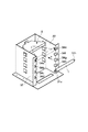
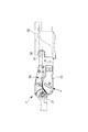
次に、本実施例にて、画像形成装置本体100Aに対して装着可能とされるプロセスカートリッジ7(7a、7b、7c、7d)について、図2及び図3を用いて説明する。
(Process cartridge)
Next, the process cartridge 7 (7a, 7b, 7c, 7d) that can be attached to the image forming apparatus
尚、イエロー色のトナーを収納したプロセスカートリッジ7a、シアン色のトナーを収納したプロセスカートリッジ7b、マゼンタ色のトナーを収納したプロセスカートリッジ7c、ブラック色のトナーを収納したプロセスカートリッジ7dは同一構成である。図2は、トナーを収納したプロセスカートリッジ7(7a、7b、7c、7d)の主断面である。
The
感光体ユニット50は、感光体ドラム1が軸受31(31a、31b)(図3)を介してクリーニング枠体51に回転自在に取り付けてられている。感光体ドラム1の周上には、感光体ドラム1の表面を一様に帯電させるための帯電ローラ2、及び、感光体ドラム1上に残ったトナーTを除去するためのクリーニングブレード60が配置されている。そして、更に、クリーニングブレード60によって感光体ドラム1表面から除去された残留トナーは、トナー送り機構52によってクリーニング枠体後方に設けられた廃トナー室51Aに順次送られる。そして、駆動モータ(不図示)の駆動力を伝達することにより、感光体ドラム1を画像形成動作に応じて図中反時計回りに回転駆動させる。
In the
現像ユニット4は、感光体ドラム1と接触して矢印W方向に回転する現像剤担持体としての現像ローラ40、及び、トナーが収容された現像剤収納容器41と現像枠体46とを備えている。現像ローラ40は軸受部材(不図示)を介して回転自在に現像枠体46に支持される。また現像ローラ40の周上には、現像ローラ40と接触して矢印Z方向に回転する供給ローラ44と現像剤規制部材としての現像ブレード45がそれぞれ配置されている。
The developing
更に、現像剤収納容器41内には収容されたトナーを撹拌すると共に、供給ローラ44に搬送するための第一攪拌部材42及び第二攪拌部材43が設けられている。
Further, a first agitating
そして、現像ユニット4は、ピン49によって現像ユニット4全体が感光体ドラムユニット50に対して揺動自在に支持された吊り構造となっている。そして、プロセスカートリッジ7単体(画像形成装置本体100Aに装着しない)状態においては、加圧ばね55によって現像ユニット4が感光体ドラムユニットに対して常に付勢されている。そして、支持軸49を中心に回転モーメントにより現像ローラ40が感光体ドラム1に接触する。
The developing
また、現像ユニット4の外側にはサイドカバー72(図4)が設けられている。感光ドラムユニット50の側面と現像ユニット4のサイドカバー72によりプロセスカートリッジ7の側面が形成される。
Further, a side cover 72 (FIG. 4) is provided outside the developing
現像時、第一攪拌部材42及び第二攪拌部材43によって、収納されたトナーが供給ローラ44へ搬送される。すると、図中矢印Z方向に回転する供給ローラ44が、そのトナーを、図中矢印W方向に回転する現像ローラ40との摺擦によって、現像ローラ40に供給し、現像ローラ40上に担持させる。
During development, the stored toner is conveyed to the
現像ローラ40上に担持されたトナーは、現像ローラ40の回転に伴い現像ブレード44に至り、現像ブレード45がトナーを規制して所定のトナー薄層に形成する。さらに、現像ローラ40上のトナー薄層は、感光体ドラム1と現像ローラ40とが接触する現像部に搬送される。そして、現像部において、電源(不図示)から現像ローラ40に印加された直流現像バイアスにより、感光体ドラム1の表面に形成されている静電潜像にトナーを付着させて、潜像を現像する。現像に寄与せずに現像ローラ40の表面に残留したトナーは、現像ローラ40の回転にともない現像枠体46内に戻され、供給ローラ44との摺擦部で現像ローラ40から剥離、回収される。回収されたトナーは、第一攪拌部材42及び第二攪拌部材43により残りのトナーと撹拌混合される。
The toner carried on the developing
本実施例のように感光体ドラム1と現像ローラ40が接触して現像を行なう接触現像方式においては、感光体ドラム1は剛体とし、現像ローラ40は弾性体を有するローラとすることが好ましい。この弾性体としては、ソリッドゴム単層やトナーへの帯電付与性を考慮してソリッドゴム層上に樹脂コーティングを施したもの等が用いられる。
In the contact development system in which development is performed by contacting the
プロセスカートリッジ7の画像形成装置本体100Aへの装着は以下のように行われる。ここで、長手方向とは感光体ドラム1の軸方向を指し、断面方向とは感光体ドラム1の軸に直交する方向を指している。
The
図3及び図4に示すように、プロセスカートリッジ7の画像形成装置本体100Aへと装着する際は、矢印Y方向からプロセスカートリッジガイド25に沿って、プロセスカートリッジ7を本体内部へ挿入する。その後、ガイド溝34(34a、34e;34b、34f;34c、34g;34d、34h)に感光体ドラム1を支持する軸受31(31a、31b)を挿入する。
As shown in FIGS. 3 and 4, when the
そして、図6に示すように軸受31がガイド溝34の突き当て面37、38に押し付けられることでプロセスカートリッジ7の位置が決まる。一方、長手方向はガイド部材25とプロセスカートリッジ7の側面でラフガイドを行う。その後、画像形成装置本体100Aの側面からの押圧手段(不図示)によりドラムユニット側面の位置決め部が画像形成装置本体100Aの所定の位置に押圧され、長手方向の位置決めが完了する。
As shown in FIG. 6, the position of the
画像形成装置本体100A内でのプロセスカートリッジ7の断面方向の保持は、図5に示す方法で行われる。
The
つまり、左右側板32には軸39が加締められており、軸39にはねじりコイルバネ30が支持され、その端部30aが左右側板の穴32aにはまり込み固定されている。プロセスカートリッジ7がない状態においては、ねじりコイルバネ30は左右側板からの曲げ起こし32bにより回転方向に規制されている。そしてプロセスカートリッジ7が挿入されると、ねじりコイルバネ30は時計周り方向にその力に反しながら回転し、軸受31を乗り越えたとき、図5のように位置し、矢印F方向に押圧し、プロセスカートリッジを位置決めする。
That is, the
次に、本発明の主要部分である光透過現像剤(トナー)残量検知方法及び検知装置200の構成について図2、及び、図7〜図9を用いて説明する。
Next, the structure of the light transmission developer (toner) remaining amount detection method and the
(光透過トナー残量検知)
図2に示すように、トナーTを収納する現像剤収納容器41内には、現像ローラ40及び供給ローラ44に近い側の第一攪拌部材42と遠い側の第二攪拌部材43とが設けられている。そして、それぞれの攪拌部材42、43がある位相差をもって等速で回転することで、供給ローラ44にトナーTを搬送している。トナーTの消費が進むと、図2に示すように、供給ローラ44の外周領域部と第一攪拌部材42の回転領域の下方領域に、トナーTが残る状態になる。
(Light transmission toner remaining amount detection)
As shown in FIG. 2, in the
ところで、図2及び図7に示すように、トナーTを収納する現像剤収納容器41には、トナー残量検知装置200を構成する一対の光透過窓54A、54Bが取り付けられている。即ち、第一攪拌部材42の攪拌中心の下方には下光透過窓54Aが、また、第一攪拌部材42の攪拌中心の上方には上光透過窓54Bがそれぞれ現像剤収納容器41の内側の面より突出した形で取り付けられている。そして、これら一対の下光透過窓54Aと上光透過窓54Bによって、現像剤残量検知の光が透過する光路を確保している。
2 and 7, a pair of light transmission windows 54 </ b> A and 54 </ b> B constituting the toner remaining
ここで、第一攪拌部材42が回転することによって、第一攪拌部材42を構成するシート部材42Aが、上光透過窓54Bと、下光透過窓54Aに摺接し、それぞれの窓の内側に付着したトナーTを掻き取っている。
Here, by the first stirring
本実施例の検知装置200によれば、光の透過方法は、画像形成装置本体100Aに取り付けられた発光ダイオード(LED)等の発光部62から検知光Lが出射される。そして、下光透過窓54Aを透過し、更に上光透過窓54Bを透過し、画像形成装置本体100に取り付けられたフォトトランジスタ等の受光部63で受光される。
According to the
この時のトナーTと検知光Lによる光透過時間tとの関係を図8に示す。検知光Lの受光時間(透過時間)はトナー量が少ないほど長く、トナー量が多いほど短いというように、トナー量に対し比例的に変化する。CPUは、この受光時間の信号を用いることでトナー残量%値を算出する。ここで、「トナー残量%値」とは、初期満杯時のトナー量を100%とした時、印字後残っているトナー量を%で示した値を言う。 FIG. 8 shows the relationship between the toner T and the light transmission time t by the detection light L at this time. The light receiving time (transmission time) of the detection light L is proportional to the amount of toner, such that it is longer as the amount of toner is smaller and shorter as the amount of toner is larger. The CPU calculates the remaining toner% value by using the light reception time signal. Here, the “toner remaining amount% value” refers to a value indicating the toner amount remaining after printing in% when the toner amount at the time of initial full is 100%.
ところで、近年、電子写真方式の画像形成装置に求められる画像印刷スピード(プロセススピード)は、年々速くなってきている。プロセススピードが速くなればそれだけ多くのトナーを現像ローラに供給しなければならず、そのため、トナー攪拌部材もプロセススピードに対応した速い回転速度に設定する必要がある。トナー攪拌部材の回転速度が速くなれば、前述した検知光がトナー容器を透過する時間にも影響が現われてくる。これは、トナー攪拌部材の回転速度によってトナー容器内で攪拌されるトナーの流動性が変わるためである。 Incidentally, in recent years, image printing speed (process speed) required for an electrophotographic image forming apparatus has been increasing year by year. As the process speed increases, so much toner must be supplied to the developing roller. Therefore, the toner stirring member also needs to be set to a high rotation speed corresponding to the process speed. If the rotation speed of the toner stirring member is increased, the above-described time for the detection light to pass through the toner container will also be affected. This is because the fluidity of the toner stirred in the toner container changes depending on the rotation speed of the toner stirring member.
つまり、トナー攪拌部材の回転速度が遅ければ、トナーはそれほど撹拌されず、トナーと混入する空気が少なくなり、トナーの流動性は低くなる。逆に、トナー攪拌部材の回転速度が速ければ、トナーが多く攪拌され、その結果、トナー中に空気が大量に混入され、トナー攪拌部材の回転速度が遅い場合よりトナーの流動性が高くなる。 That is, if the rotation speed of the toner stirring member is slow, the toner is not stirred so much, the air mixed with the toner is reduced, and the fluidity of the toner is lowered. Conversely, if the rotation speed of the toner stirring member is high, a large amount of toner is stirred, and as a result, a large amount of air is mixed in the toner, and the fluidity of the toner becomes higher than when the rotation speed of the toner stirring member is low.
トナーの流動性が低い場合、トナー攪拌部材のシート部が光透過窓の表面上を覆っているトナーを掻き取ってからトナーが光透過窓を再度覆ってしまうまでの状態は、トナーの流動性が高い場合と比較して安定している。そのため、検知光がトナー容器内を透過する時間が安定し、トナー残量を精度良く検知することが可能となる。 If the toner fluidity is low, the state from when the toner stirring member sheet portion scrapes off the toner covering the surface of the light transmitting window until the toner covers the light transmitting window again is the toner fluidity. Is more stable than when it is high. For this reason, the time during which the detection light passes through the toner container is stabilized, and the remaining amount of toner can be detected with high accuracy.
一方、トナーの流動性が高い場合、トナー攪拌部材のシート部が光透過窓の表面上を覆っているトナーを掻き取っても、トナーの挙動が安定せず、すぐにトナーが光透過窓を覆ってしまう。そのため、検知光がトナー容器内を透過する時間は短くなるだけでなく、トナー残量検知精度にばらつきが多くなってしまう。つまり、トナー容器内のトナー残量を正確に把握できなくなってしまう。 On the other hand, when the fluidity of the toner is high, even if the sheet portion of the toner stirring member scrapes off the toner covering the surface of the light transmission window, the behavior of the toner is not stable, and the toner immediately opens the light transmission window. I will cover it. Therefore, not only the time for the detection light to pass through the toner container is shortened, but also the variation in the remaining toner detection accuracy increases. That is, the remaining amount of toner in the toner container cannot be accurately grasped.
これらの問題を解決するため、本実施例では残量検知を行なうタイミングでトナー攪拌部材の回転速度を遅くする、つまり、トナーの流動性が低い状態で残量検知を行なっている。しかし、そのためには現像ローラに供給するべきトナー量を確保するため、画像形成中以外のタイミングで残量検知を行なわなくてはならない。 In order to solve these problems, in the present embodiment, the rotation speed of the toner agitating member is decreased at the timing of detecting the remaining amount, that is, the remaining amount is detected in a state where the toner fluidity is low. However, for that purpose, in order to secure the amount of toner to be supplied to the developing roller, the remaining amount must be detected at a timing other than during image formation.
また、残量検知を行なうにはある程度の時間を要するため、残量検知を頻繁に行なえば、つまり残量検知の間隔を短く設定すれば、それだけ印刷生産性を低下させることにつながってしまう。それゆえ、残量検知を行なうタイミングは、印刷生産性を必要以上に低下させないことを考慮した設定にしなければならない。 In addition, since it takes a certain amount of time to detect the remaining amount, if the remaining amount detection is frequently performed, that is, if the interval of the remaining amount detection is set to be short, the printing productivity is reduced accordingly. Therefore, the timing for performing the remaining amount detection must be set in consideration of not reducing print productivity more than necessary.
これとは逆に、残量検知を行なう間隔を長くタイミングを遅く設定し過ぎると、残量検知を行なうタイミング間に実行された画像形成のトナー消費量が多い場合には、トナー残量の検知結果を示す値が前回検知した残量から大きく変化してしまうことになる。このため、トナーが無くなったことを検知するタイミングを逃してしまうことにつながってしまう。 On the contrary, if the remaining amount detection interval is set too long and the timing is set too late, if the amount of toner consumed for image formation executed between the remaining amount detection timings is large, the remaining toner amount is detected. The value indicating the result is greatly changed from the remaining amount detected last time. For this reason, it will lead to missing the timing which detects that the toner has run out.
もし、トナー容器内にトナーが無くなっているにも関わらず、それをユーザに知らせることが遅れ、プリント動作を続けてしまうと、画像弊害を引き起こすことにもなりかねない。さらに、ユーザがプロセスカートリッジ交換時期を逃してしまうことにもつながる。
これらの事情を考慮して本実施例では、トナー消費量に応じて所定のタイミングでトナー残量検知シーケンスを行なっている。
If there is no toner in the toner container and it is delayed to notify the user of the toner container and the printing operation is continued, it may cause a bad image. In addition, the user may miss the process cartridge replacement time.
In consideration of these circumstances, in this embodiment, the toner remaining amount detection sequence is performed at a predetermined timing according to the toner consumption.
(残量検知シーケンス)
本実施例において、光透過トナー残量検知装置200によりトナー残量%値を算出しているタイミングは画像形成動作時以外である。具体的には、現像ローラ40の累積回転時間Tsが所定の値に達することにより画像形成動作を停止するタイミングにおいて実行される。
(Remaining amount detection sequence)
In this embodiment, the timing of calculating the remaining toner% value by the light transmitting toner remaining
ここで、画像形成動作とは画像情報に基づいてレーザービームを照射し形成された感光体ドラム1上の静電潜像を、現像ローラ40に担持されたトナーTにより現像することをいう。なお、画像形成時とは、感光体ドラム上の静電潜像を現像ローラに担持されたトナーTにより現像している時を指す。非画像形成時は、画像形成時以外のときを指す。即ち、感光体ドラム上の静電潜像を現像していない時である。また、現像ローラ40の累積回転時間Tsは所定の値まで達すると、一旦リセットされ、再度、累積回転時間の測定を行なうよう設定されている。
Here, the image forming operation refers to developing the electrostatic latent image on the
残量検知を非画像形成時に行なっている理由は、画像形成時と異なり現像ローラ40へのトナー供給不足が原因で発生する画像弊害等の影響を受けることが無いため、第一攪拌部材42の回転速度を遅く設定できるからである。本実施例では、画像形成時の第一攪拌部材42の回転速度約60rpmに対し、残量検知時のトナー攪拌搬送部材42の回転速度約30rpmと画像形成動作時の1/2に設定している。
The reason why the remaining amount detection is performed at the time of non-image formation is not affected by image adverse effects caused by insufficient toner supply to the developing
残量検知時、第一攪拌部材の回転速度を遅く設定することで、現像剤収納容器41内のトナーの流動性は低くすることが可能となる。トナーの流動性が低ければ、トナー攪拌部であるシート部42Aが光透過窓の表面上を覆っているトナーを掻き取ってからトナーが光透過窓を再度覆ってしまうまでの時間が、トナーの流動性が高い時よりも安定する。従って、検知光が現像剤収納容器41内を透過する時間が安定し、トナー残量を精度良く検知することが可能となる。
When the remaining amount is detected, the fluidity of the toner in the
そして、本実施形における残量検知シーケンスでは、画像形成動作の停止を決定する現像ローラ40の累積回転時間Tsの設定を二種類設け、トナー消費量に応じて残量検知を行なう間隔を変えることを可能としている。これにより、トナー消費量が多い画像形成が行なわれた場合、即ち、トナーの残量の減少量が所定の値より多い場合には、次回の残量検知のタイミングを早める。これは、トナー消費量が多い画像形成が行なわれた場合は、次回形成される画像もトナー消費量が多い画像であると予想されるため、残量検知のタイミングを早めているのである。その後、トナー消費量が少ない画像形成が行なわれた場合には、即ち、トナーの残量の減少量が所定の値より少ない場合には、一度早めた残量検知のタイミングを元に戻す、即ち、タイミングを遅くすることが可能となる。これは、トナー消費量が少ない画像形成が行なわれた場合は、次回形成される画像もトナー消費量が少ない画像であると予想されるため、残量検知のタイミングを遅くすることで印刷生産性を必要以上に遅くすることがなくなる。
In the remaining amount detection sequence in the present embodiment, two types of setting of the cumulative rotation time Ts of the developing
本実施例において、画像形成動作の停止を決定する現像ローラ40の累積回転時間Tsの通常の設定は220s(秒)(Ts1)であり、トナー消費量によりタイミングを早めた場合の設定は120s(Ts2)である。
In this embodiment, the normal setting of the cumulative rotation time Ts of the developing
ここで、本実施例におけるトナー消費量を判断する方法について説明する。連続した二回の残量検知から算出されたトナー残量%値の差を求める。 Here, a method for determining the toner consumption amount in this embodiment will be described. The difference between the remaining toner% values calculated from the two consecutive remaining amount detections is obtained.
そして、そのトナー残量%値の差が予め設定された閾値N(本実施例においては7%)より大きければ、トナー消費量の多い画像形成であると判断し、現像ローラ40の累積回転時間Ts2(本実施例においては120s)に残量検知を行なうタイミングを早める。また、一度早められた残量検知タイミングは、別途設定された閾値M(本実施例においては4%)より小さければ、トナー消費量が少ないと判断する。そして、残量検知のタイミングを現像ローラ40の累積回転時間Ts1(本実施例においては220s)へと元に戻す。即ち、残量検知のタイミングを遅くする。
If the difference between the remaining toner percentage values is larger than a preset threshold value N (7% in this embodiment), it is determined that the image formation is a large amount of toner consumption, and the cumulative rotation time of the developing
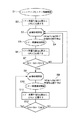
以下に、本実施例でのトナー残量検知シーケンスについて図9のフローチャートを用いて説明する。
S1:イニシャライズ時トナー残量検知を開始。
(イニシャライズは、電源ON時及びプロセスカートリッジの交換やジャム処理等で装置本体の前カバーを開閉した時に行なわれる。)
S2:残量検知シーケンスを実行し、検知光の通過時間からトナー残量%値Q(n)を算出する。そして、画像形成装置に備えたCPUに記憶する。
(ここで、nは残検シーケンスを行なった回数を示しており、イニシャライズ毎にリセットされる。)
S3:画像形成動作開始。
S4:現像ローラ回転時間Ts1が、200s以上、240s以下の範囲内に至った時点で画像形成動作を停止する。本実施例では、現像ローラ回転時間Ts1が、本実施例では、220sのタイミングで画像形成動作停止。
S5:トナー残量検知を開始。
S6:残量検知シーケンスを実行し、検知光の通過時間からトナー残量%値Q(n)を算出する。そして、画像形成装置に備えたCPUに記憶する。
S7:Q(n)−Q(n−1)≧N(=7)の場合、即ち、トナー消費量が多い場合は、S8に移行する。また、Q(n)−Q(n−1)<Nの場合、即ち、トナー消費量が少ない場合はS3に移行する。ここで、Nは、トナー消費量を判断するための閾値。
S8:画像形成開始。
S9:現像ローラ回転時間Ts2が、100s以上、140s以下の範囲内に至った時点で画像形成動作を停止する。本実施例では、現像ローラ回転時間Ts2が、本実施例では120sのタイミングで画像形成動作停止。
S10:トナー残量検知を開始。
S11:残量検知シーケンスを実行し、検知光の通過時間からトナー残量%値Q(n)を算出する。そして、画像形成装置に備えたCPUに記憶する。
S12:Q(n)−Q(n−1)≧M(=4)の場合、即ち、トナー消費量が多い場合はS8に移行し、残量検知タイミングは早めた状態に維持する。また、Q(n)−Q(n−1)<Mの場合、即ち、トナー消費量が少ない場合はS3に移行し、残量検知タイミングは遅くする。ここで、Mはトナー消費量を判断するための閾値。
The toner remaining amount detection sequence in the present embodiment will be described below with reference to the flowchart of FIG.
S1: Toner remaining amount detection starts at initialization.
(Initialization is performed when the power is turned on and when the front cover of the apparatus main body is opened and closed due to process cartridge replacement, jam processing, etc.)
S2: A remaining amount detection sequence is executed, and a toner remaining amount% value Q (n) is calculated from the passage time of the detection light. And it memorize | stores in CPU provided in the image forming apparatus.
(Here, n indicates the number of times the residual detection sequence has been performed, and is reset at each initialization.)
S3: Start image forming operation.
S4: The image forming operation is stopped when the developing roller rotation time Ts1 falls within the range of 200 s to 240 s. In this embodiment, the image forming operation is stopped when the developing roller rotation time Ts1 is 220 s in this embodiment.
S5: The toner remaining amount detection is started.
S6: A remaining amount detection sequence is executed, and a toner remaining amount% value Q (n) is calculated from the passage time of the detection light. And it memorize | stores in CPU provided in the image forming apparatus.
S7: If Q (n) −Q (n−1) ≧ N (= 7), that is, if the toner consumption is large, the process proceeds to S8. If Q (n) -Q (n-1) <N, that is, if the toner consumption is small, the process proceeds to S3. Here, N is a threshold value for determining the toner consumption.
S8: Start image formation.
S9: The image forming operation is stopped when the developing roller rotation time Ts2 falls within the range of 100 s to 140 s. In this embodiment, the image forming operation is stopped when the developing roller rotation time Ts2 is 120 s in this embodiment.
S10: The toner remaining amount detection is started.
S11: A remaining amount detection sequence is executed, and a toner remaining amount% value Q (n) is calculated from the passage time of the detection light. And it memorize | stores in CPU provided in the image forming apparatus.
S12: When Q (n) −Q (n−1) ≧ M (= 4), that is, when the amount of toner consumption is large, the process proceeds to S8, and the remaining amount detection timing is maintained in an advanced state. Furthermore, Q (n) -Q (n -1) < For M, i.e., if the toner over consumption is small, the process proceeds to S3, the remaining amount detection timing is slow. Here, M is a threshold value for determining the toner consumption.
本実施例では、このトナー残量検知シーケンスを行うことにより、トナー消費量の多い画像形成においても、残量検知を行なうタイミングを早めてトナー残量%値の大きな変化をできる限り抑えることができる。よって、精度が高いトナー残量検知を行なうことが可能である。また、残量検知タイミングを早めた後、トナー消費量が少なくなった場合は、次回の残量検知までの時間を元に戻す、即ち、残量検知タイミングを遅くすることができるので、必要以上に印刷生産性を損なわずトナー残量検知を行うことが可能となる。 In this embodiment, by performing this toner remaining amount detection sequence, even in image formation with a large amount of toner consumption, the timing of performing the remaining amount detection can be advanced to suppress a large change in the remaining toner amount% as much as possible. . Therefore, it is possible to detect the remaining amount of toner with high accuracy. In addition, if the toner consumption decreases after the remaining amount detection timing is advanced, the time until the next remaining amount detection is restored, that is, the remaining amount detection timing can be delayed, so that it is more than necessary. In addition, it is possible to detect the remaining amount of toner without impairing printing productivity.
なお、本実施例のトナー消費量判断閾値N、M及び現像ローラ回転時間Ts1、Ts2の設定、また画像形成時並びに残量検知時の攪拌速度は使用される装置に応じて好適となる値を選択すればよい。 It should be noted that the toner consumption determination thresholds N and M and the developing roller rotation times Ts1 and Ts2 of this embodiment, and the stirring speed at the time of image formation and detection of the remaining amount have values that are suitable for the apparatus used. Just choose.
また、本発明は電子写真画像形成装置がプロセスカートリッジ方式とされていない場合においても適用することができ、本実施例と同様の効果を奏し得る。 In addition, the present invention can be applied even when the electrophotographic image forming apparatus is not a process cartridge type, and the same effects as in the present embodiment can be obtained.
参考例
次に、本発明の参考例について説明する。
Reference Example will be described reference example of the present invention.
本参考例では、実施例1にて説明した電子写真画像形成装置100及びプロセスカートリッジ7において、トナー消費量に応じて残量検知を行なうタイミングを変えるためのトナー消費量判断方法を変更して、実施例1と同等の効果があることを特徴とする。本参考例では画像情報を基にして残量検知のタイミングを変えている。具体的に言えば、画像情報の印字率を基にして残量検知のタイミングを変えている。
In this reference example, in the electrophotographic
なお、本参考例においては、そのほとんどが実施例1で説明した電子写真画像形成装置100及びプロセスカートリッジ7を用いるので、電子写真画像形成装置100及びプロセスカートリッジ7の詳細な説明は省略する。本参考例においても、実施例1と同様にトナー残量検知の際の攪拌部材の回転速度を画像形成時の攪拌部材の回転速度よりも遅くしている。
In this reference example, most of the electrophotographic
本参考例の電子写真画像形成装置100には、画像形成の元となる画像情報(印字情報)を処理するためにコントローラ300(図1、図11参照)が備えられている。コントローラ300は入力される画像情報(印字情報)より印字率を確定し、トナー消費量を算出できる。よって、残量検知を行なうタイミングを早めるか、または通常通りに行なうかを判断することが可能である。そして、コントローラ300には、図11のブロック図に示すように発光部62と受光部63が接続されている。そして発光部62と受光部63によってコントローラ300に前述した残量検知信号が入力される。
The electrophotographic
つまり、入力された画像情報(印字情報)が印字率P%以上(本参考例においては35%)である場合、即ちトナー消費量の多い画像形成であるとコントローラ300が判断した場合、次回残量検知を行なうタイミングを早める。現像ローラ40の累積回転時間Ts2(本参考例においては120s)にて残量検知を行なう。また、入力された画像情報(印字情報)が印字率P%より小さい(本参考例においては35%)場合、即ちトナー消費量の少ない画像形成であるとコントローラ300が判断した場合、次回残量検知のタイミングを現像ローラ40の累積回転時間Ts1(本参考例においては220s)と通常通りに戻す。
In other words, when the input image information (printing information) is equal to or higher than the printing rate P% (35% in this reference example), that is, when the
以下に、本参考例でのトナー残量検知シーケンスについて図10のフローチャートを用いて説明する。
S1:画像形成装置に備えられたコントローラに印字情報入力。
S2:コントローラで印字率がP%以上かを判断。P%以上の場合はS3に移行する。P%以下の場合はS7へ移行する。ここで、Pは、トナー消費量を判断する閾値。
S3:画像形成動作開始。
S4:現像ローラ回転時間Ts2が、100s以上、140s以下の範囲内に至った時点で画像形成動作を停止する。本参考例では、現像ローラ回転時間Ts2が、120sのタイミングで画像形成動作停止。
S5:トナー残量検知を開始。
S6:残量検知シーケンスを実行し、検知光の通過時間からトナー残量%値Q(n)を算出する。そして、画像形成装置に備えたCPUに記憶する。
S7:画像形成動作開始。
S8:現像ローラ回転時間Ts1が、200s以上、240s以下の範囲内に至った時点で画像形成動作を停止する。本参考例では、現像ローラ回転時間Ts1が、220sのタイミングで画像形成動作停止。その後、S5へ移行。
The toner remaining amount detection sequence in this reference example will be described below with reference to the flowchart of FIG.
S1: Print information is input to a controller provided in the image forming apparatus.
S2: The controller determines whether the printing rate is P% or more. If P% or more, the process proceeds to S3. If P% or less, the process proceeds to S7. Here, P is a threshold value for determining the toner consumption.
S3: Start image forming operation.
S4: The image forming operation is stopped when the developing roller rotation time Ts2 reaches the range of 100 s or more and 140 s or less. In this reference example, the image forming operation is stopped when the developing roller rotation time Ts2 is 120s.
S5: The toner remaining amount detection is started.
S6: A remaining amount detection sequence is executed, and a toner remaining amount% value Q (n) is calculated from the passage time of the detection light. And it memorize | stores in CPU provided in the image forming apparatus.
S7: Start image forming operation.
S8: The image forming operation is stopped when the developing roller rotation time Ts1 falls within the range of 200 s to 240 s. In this reference example, the image forming operation is stopped when the developing roller rotation time Ts1 is 220s. Thereafter, the process proceeds to S5.
本参考例では、このトナー残量検知シーケンスを行うことにより、トナー消費量の多い画像形成においても、残量検知を行なうタイミングを早めてトナー残量%値の大きな変化を最小限に抑えることができる。よって、精度が高いトナー残量検知を行なうことが可能となる。また、残量検知タイミングを早めた後、トナー消費量が少なくなった場合は、次回の残量検知までの時間を元に戻すことができる。したがって、必要以上に印刷生産性を損なわずトナー残量検知を行うことが可能となる。 In this reference example, by performing this toner remaining amount detection sequence, even in image formation with a large amount of toner consumption, the timing for performing the remaining amount detection can be advanced to minimize a large change in the toner remaining amount% value. it can. Therefore, it is possible to detect the remaining amount of toner with high accuracy. If the toner consumption is reduced after the remaining amount detection timing is advanced, the time until the next remaining amount detection can be restored. Therefore, it is possible to detect the remaining amount of toner without losing the printing productivity more than necessary.
なお、上記参考例では、入力された画像情報の印字率がすべて同じ場合を想定している。しかしながら、数種類の画像情報が一度に入力された場合では、入力された画像情報の印字率判断は、その中で1番印字率が高いものを判断基準とするようにしても良い。例えば、印字率20%(低印字率)の画像情報と、印字率80%(高印字率)の画像情報とが入力された場合は、トナー消費量の多い画像形成がされると判断(印字率80%を判断基準)し、残量検知タイミングを早めることが考えられる。 In the above reference example, it is assumed that the printing rates of the input image information are all the same. However, when several types of image information are input at a time, the determination of the print rate of the input image information may be based on the highest print rate among them. For example, when image information with a printing rate of 20% (low printing rate) and image information with a printing rate of 80% (high printing rate) are input, it is determined that an image with a large amount of toner consumption is formed (printing). It is conceivable that the remaining amount detection timing is advanced by determining the rate 80%.
なお、本参考例のトナー消費量判断閾値P及び現像ローラ回転時間Ts1、Ts2の設定、また画像形成時並びに残量検知時の攪拌部材の回転速度は使用される装置に応じて好適となる値を選択すればよい。また、残量検知の間隔を決定する基準として現像ローラの回転時間を基準としているがこれに限られるものではない。 It should be noted that the setting of the toner consumption determination threshold value P and the developing roller rotation times Ts1 and Ts2, and the rotation speed of the stirring member at the time of image formation and detection of the remaining amount in this reference example are values that are suitable for the apparatus used. Should be selected. Further, although the rotation time of the developing roller is used as a reference as a reference for determining the remaining amount detection interval, it is not limited to this.
また、本参考例は電子写真画像形成装置がプロセスカートリッジ方式とされていない場合においても適用することができ、本参考例と同様の効果を奏し得る。 Further, the present reference example can be applied even when the electrophotographic image forming apparatus is not of the process cartridge type, and the same effect as the present reference example can be obtained.
上記実施例及び参考例ではトナーを攪拌する攪拌部材が残量検知のための光透過窓を摺擦する構成としているがこれに限られるものではない。 In the above-described embodiments and reference examples , the stirring member that stirs the toner is configured to rub against the light transmission window for detecting the remaining amount, but is not limited thereto.
なお、上記実施例及び参考例では、光透過による残量検知を例に挙げたがこれに限られるものではない。例えばトナー容器内の静電容量を検知することによりトナーの残量検知を行なう場合であっても、残量検知時は攪拌速度を落として残量検知の精度を高くするような場合は、本願発明を適用することができる。 In the above embodiment and reference example , the remaining amount detection by light transmission is described as an example, but the present invention is not limited to this. For example, even when the remaining amount of toner is detected by detecting the electrostatic capacity in the toner container, when the remaining amount is detected, the stirring speed is decreased to increase the accuracy of remaining amount detection. The invention can be applied.
1(1a〜1d) 電子写真感光体ドラム
2(2a〜2d) 帯電手段
3(3a〜3d) スキャナユニット
4(4a〜4d) 現像ユニット
5 静電転写手段
5(6a〜6d) クリーニング手段
7(7a〜7d) プロセスカートリッジ
40 現像ローラ(現像剤担持体)
41 現像剤収納容器
42 第一攪拌搬送部材
43 第二攪拌搬送部材
44 供給ローラ
45 現像ブレード
50(50a〜50d) 感光体ユニット
51 クリーニング枠体
54A 下光透過窓
54B 上光透過窓
62 発光部
63 受光部
100 画像形成装置
100A 画像形成装置本体
200 現像剤残量検知手段
1 (1a to 1d) Electrophotographic photosensitive drum 2 (2a to 2d) Charging means 3 (3a to 3d) Scanner unit 4 (4a to 4d) Developing
41
Claims (5)
前記静電潜像を現像する現像剤を収納する現像剤収納容器と、
前記現像剤収納容器内の前記現像剤の残量検知を行う検知装置と、
前記現像剤収納容器内の現像剤を攪拌する現像剤攪拌部材と、
を有する画像形成装置であって、
前記検知装置は、非画像形成時に前記現像剤収納容器内に設けられた透過窓を透過する検知光によって前記現像剤の残量を検知し、前記現像剤攪拌部材の回転速度は、画像形成動作時よりも前記残量検知時の方が遅くなり、第一の残量検知時に前記検知装置により検知された第一現像剤残量と、前記第一の残量検知時よりも後の第二の残量検知時に前記検知装置により検知された第二現像剤残量とに基いて、前記第二の残量検知時と前記第二の残量検知の次回の第三の残量検知時との検知間隔を変更するようになっており、前記第一現像剤残量と、前記第二現像剤残量との差分が所定値より大きい場合に、前記検知間隔を短くすることを特徴とする画像形成装置。 An image carrier on which an electrostatic latent image is formed;
A developer storage container for storing a developer for developing the electrostatic latent image;
A detection device for detecting a remaining amount of the developer in the developer storage container;
A developer stirring member for stirring the developer in the developer storage container;
An image forming apparatus having
The detection device detects the remaining amount of the developer by detection light transmitted through a transmission window provided in the developer storage container during non-image formation, and the rotation speed of the developer agitating member is determined by an image forming operation. The remaining amount is detected later than the time, the first developer remaining amount detected by the detection device when the first remaining amount is detected, and the second remaining after the first remaining amount is detected. Based on the second developer remaining amount detected by the detection device at the time of remaining amount detection, the second remaining amount detection time and the next third remaining amount detection of the second remaining amount detection, The detection interval is shortened when the difference between the first developer remaining amount and the second developer remaining amount is greater than a predetermined value. Image forming apparatus.
前記現像剤は、前記現像剤収納容器から前記現像剤担持体に供給され、
前記検知間隔は、前記現像剤担持体の累積回転数により決定され、
前記検知間隔の変更は、前記現像剤担持体の累積回転数を変更することで行なわれることを特徴とする請求項1乃至3のいずれかに記載の画像形成装置。 A developer carrying body carrying the developer;
The developer is supplied from the developer container to the developer carrier,
The detection interval is determined by the cumulative number of rotations of the developer carrier.
The change of the detection interval, the image forming apparatus according to any one of claims 1 to 3, characterized in that is carried out by changing the accumulated rotation number of the developer carrier.
Priority Applications (2)
| Application Number | Priority Date | Filing Date | Title |
|---|---|---|---|
| JP2006092581A JP4078372B2 (en) | 2005-04-13 | 2006-03-29 | Electrophotographic image forming apparatus |
| US11/398,726 US7505699B2 (en) | 2005-04-13 | 2006-04-06 | Electrophotographic image forming apparatus |
Applications Claiming Priority (2)
| Application Number | Priority Date | Filing Date | Title |
|---|---|---|---|
| JP2005115989 | 2005-04-13 | ||
| JP2006092581A JP4078372B2 (en) | 2005-04-13 | 2006-03-29 | Electrophotographic image forming apparatus |
Related Child Applications (1)
| Application Number | Title | Priority Date | Filing Date |
|---|---|---|---|
| JP2007174637A Division JP2007249245A (en) | 2005-04-13 | 2007-07-02 | Electrophotographic image forming apparatus |
Publications (3)
| Publication Number | Publication Date |
|---|---|
| JP2006317914A JP2006317914A (en) | 2006-11-24 |
| JP2006317914A5 JP2006317914A5 (en) | 2007-03-15 |
| JP4078372B2 true JP4078372B2 (en) | 2008-04-23 |
Family
ID=37108587
Family Applications (1)
| Application Number | Title | Priority Date | Filing Date |
|---|---|---|---|
| JP2006092581A Expired - Fee Related JP4078372B2 (en) | 2005-04-13 | 2006-03-29 | Electrophotographic image forming apparatus |
Country Status (2)
| Country | Link |
|---|---|
| US (1) | US7505699B2 (en) |
| JP (1) | JP4078372B2 (en) |
Families Citing this family (14)
| Publication number | Priority date | Publication date | Assignee | Title |
|---|---|---|---|---|
| JP4627191B2 (en) * | 2005-01-14 | 2011-02-09 | キヤノンファインテック株式会社 | Image forming apparatus |
| JP4718209B2 (en) * | 2005-03-07 | 2011-07-06 | 株式会社リコー | Image forming apparatus and image forming unit |
| JP5219462B2 (en) * | 2007-01-31 | 2013-06-26 | キヤノン株式会社 | Developing device, process cartridge, and electrophotographic image forming apparatus |
| EP1953602B1 (en) | 2007-01-31 | 2014-02-26 | Canon Kabushiki Kaisha | Developing apparatus, process cartridge and image forming apparatus |
| JP2008216562A (en) * | 2007-03-02 | 2008-09-18 | Seiko Epson Corp | Image forming apparatus and image forming system |
| US7970306B2 (en) * | 2007-07-06 | 2011-06-28 | Canon Kabushiki Kaisha | Image forming apparatus including device for outputting developer remainder amount information |
| JP5315652B2 (en) * | 2007-09-19 | 2013-10-16 | 村田機械株式会社 | Image forming apparatus |
| KR100941421B1 (en) * | 2008-02-21 | 2010-02-10 | 삼성전자주식회사 | Developer storage device and image forming apparatus having the same |
| JP5056896B2 (en) * | 2010-05-14 | 2012-10-24 | ブラザー工業株式会社 | Image forming apparatus |
| JP5510363B2 (en) * | 2011-02-28 | 2014-06-04 | ブラザー工業株式会社 | Image forming apparatus |
| JP5704977B2 (en) * | 2011-03-09 | 2015-04-22 | キヤノン株式会社 | Image forming apparatus |
| JP6108290B2 (en) * | 2013-06-21 | 2017-04-05 | 株式会社リコー | Developer supply method and image forming apparatus provided with supply determination unit |
| JP6330906B2 (en) * | 2014-06-26 | 2018-05-30 | 京セラドキュメントソリューションズ株式会社 | Image reading apparatus and image forming apparatus having the same |
| JP6942993B2 (en) * | 2017-03-31 | 2021-09-29 | ブラザー工業株式会社 | Image forming device and control method |
Family Cites Families (14)
| Publication number | Priority date | Publication date | Assignee | Title |
|---|---|---|---|---|
| JP3220256B2 (en) | 1991-11-25 | 2001-10-22 | 株式会社リコー | Image forming method and image forming apparatus |
| JP3043552B2 (en) | 1993-10-04 | 2000-05-22 | シャープ株式会社 | Image stabilization device for electrophotographic equipment |
| JPH10186769A (en) | 1996-12-20 | 1998-07-14 | Canon Inc | Multicolor image forming device |
| JP3134826B2 (en) | 1997-09-30 | 2001-02-13 | キヤノン株式会社 | Image forming device |
| JP2000356901A (en) | 1999-06-15 | 2000-12-26 | Ricoh Co Ltd | Electrophotographic device |
| JP2001215786A (en) | 2000-01-31 | 2001-08-10 | Canon Inc | Developing device, process cartridge and image forming device |
| JP2001290359A (en) * | 2000-04-07 | 2001-10-19 | Canon Inc | Developer container, developer amount detecting system, process cartridge, developing device and image forming device |
| JP2001350339A (en) | 2000-06-02 | 2001-12-21 | Brother Ind Ltd | Developing cartridge and image forming device |
| JP2003131479A (en) | 2001-10-29 | 2003-05-09 | Canon Inc | Developing device, process cartridge and image forming device |
| JP2003241500A (en) | 2002-02-13 | 2003-08-27 | Canon Inc | Remaining developer quantity detecting device, process cartridge and image forming apparatus |
| JP4164277B2 (en) | 2002-03-29 | 2008-10-15 | キヤノン株式会社 | Image forming apparatus |
| JP4433698B2 (en) | 2002-10-01 | 2010-03-17 | セイコーエプソン株式会社 | Image forming apparatus and image forming method |
| JP4366160B2 (en) * | 2002-09-24 | 2009-11-18 | キヤノン株式会社 | Image forming apparatus |
| US7010237B2 (en) * | 2003-09-22 | 2006-03-07 | Canon Kabushiki Kaisha | Image forming apparatus with residual toner replenishing feature based on two detection results |
-
2006
- 2006-03-29 JP JP2006092581A patent/JP4078372B2/en not_active Expired - Fee Related
- 2006-04-06 US US11/398,726 patent/US7505699B2/en active Active
Also Published As
| Publication number | Publication date |
|---|---|
| JP2006317914A (en) | 2006-11-24 |
| US20060233560A1 (en) | 2006-10-19 |
| US7505699B2 (en) | 2009-03-17 |
Similar Documents
| Publication | Publication Date | Title |
|---|---|---|
| JP4078372B2 (en) | Electrophotographic image forming apparatus | |
| KR100673494B1 (en) | Image forming apparatus | |
| JP4402066B2 (en) | Toner replenishing device, developing device, and image forming apparatus | |
| JP3780171B2 (en) | Process cartridge and electrophotographic image forming apparatus | |
| JP2000075753A (en) | Mounting adjustment method of cleaning member, process cartridge and image forming device | |
| JP2008197147A (en) | Image forming apparatus | |
| JP4962761B2 (en) | Image forming apparatus | |
| JP4724464B2 (en) | Image forming apparatus | |
| JP2008107696A (en) | Image forming device and lifetime determination method of toner cartridge | |
| JP4392234B2 (en) | Image forming apparatus and toner supply method | |
| JP2007249245A (en) | Electrophotographic image forming apparatus | |
| JP4799149B2 (en) | Development device | |
| JP4630605B2 (en) | Image forming apparatus | |
| JP4749135B2 (en) | Image forming apparatus | |
| US8600250B2 (en) | Image forming unit and apparatus that performs stand-by charging of toner | |
| JP5510062B2 (en) | Image forming apparatus and program | |
| JP4570722B2 (en) | Image recording device | |
| JP4970312B2 (en) | Image forming apparatus | |
| JP2003241500A (en) | Remaining developer quantity detecting device, process cartridge and image forming apparatus | |
| JP2003263079A (en) | Image forming device and method for estimating life of photoreceptor used in the device | |
| US11385567B2 (en) | Image forming apparatus with developer amount prediction | |
| JPH11344908A (en) | Cartridge attached to/detached from image forming device, image forming device and control method for image forming device | |
| JP2006284999A (en) | Development device and process cartridge and electrophotographic image forming apparatus | |
| JP5697424B2 (en) | Image forming apparatus | |
| JP4776979B2 (en) | Image forming apparatus |
Legal Events
| Date | Code | Title | Description |
|---|---|---|---|
| A521 | Request for written amendment filed |
Free format text: JAPANESE INTERMEDIATE CODE: A523 Effective date: 20070130 |
|
| A621 | Written request for application examination |
Free format text: JAPANESE INTERMEDIATE CODE: A621 Effective date: 20070130 |
|
| A871 | Explanation of circumstances concerning accelerated examination |
Free format text: JAPANESE INTERMEDIATE CODE: A871 Effective date: 20070130 |
|
| A975 | Report on accelerated examination |
Free format text: JAPANESE INTERMEDIATE CODE: A971005 Effective date: 20070227 |
|
| A131 | Notification of reasons for refusal |
Free format text: JAPANESE INTERMEDIATE CODE: A131 Effective date: 20070501 |
|
| A521 | Request for written amendment filed |
Free format text: JAPANESE INTERMEDIATE CODE: A523 Effective date: 20070702 |
|
| A131 | Notification of reasons for refusal |
Free format text: JAPANESE INTERMEDIATE CODE: A131 Effective date: 20070724 |
|
| A131 | Notification of reasons for refusal |
Free format text: JAPANESE INTERMEDIATE CODE: A131 Effective date: 20071023 |
|
| A521 | Request for written amendment filed |
Free format text: JAPANESE INTERMEDIATE CODE: A523 Effective date: 20071219 |
|
| TRDD | Decision of grant or rejection written | ||
| A01 | Written decision to grant a patent or to grant a registration (utility model) |
Free format text: JAPANESE INTERMEDIATE CODE: A01 Effective date: 20080122 |
|
| A61 | First payment of annual fees (during grant procedure) |
Free format text: JAPANESE INTERMEDIATE CODE: A61 Effective date: 20080204 |
|
| R150 | Certificate of patent or registration of utility model |
Ref document number: 4078372 Country of ref document: JP Free format text: JAPANESE INTERMEDIATE CODE: R150 Free format text: JAPANESE INTERMEDIATE CODE: R150 |
|
| FPAY | Renewal fee payment (event date is renewal date of database) |
Free format text: PAYMENT UNTIL: 20110208 Year of fee payment: 3 |
|
| FPAY | Renewal fee payment (event date is renewal date of database) |
Free format text: PAYMENT UNTIL: 20120208 Year of fee payment: 4 |
|
| FPAY | Renewal fee payment (event date is renewal date of database) |
Free format text: PAYMENT UNTIL: 20130208 Year of fee payment: 5 |
|
| FPAY | Renewal fee payment (event date is renewal date of database) |
Free format text: PAYMENT UNTIL: 20140208 Year of fee payment: 6 |
|
| LAPS | Cancellation because of no payment of annual fees |