JP4069408B2 - Electronic circuit, driving method thereof, and electronic apparatus - Google Patents
Electronic circuit, driving method thereof, and electronic apparatus Download PDFInfo
- Publication number
- JP4069408B2 JP4069408B2 JP2002101837A JP2002101837A JP4069408B2 JP 4069408 B2 JP4069408 B2 JP 4069408B2 JP 2002101837 A JP2002101837 A JP 2002101837A JP 2002101837 A JP2002101837 A JP 2002101837A JP 4069408 B2 JP4069408 B2 JP 4069408B2
- Authority
- JP
- Japan
- Prior art keywords
- transistor
- voltage
- current
- voltage value
- electronic
- Prior art date
- Legal status (The legal status is an assumption and is not a legal conclusion. Google has not performed a legal analysis and makes no representation as to the accuracy of the status listed.)
- Expired - Fee Related
Links
- 238000000034 method Methods 0.000 title claims description 19
- 238000006243 chemical reaction Methods 0.000 claims description 16
- 230000008859 change Effects 0.000 claims description 11
- 239000003990 capacitor Substances 0.000 description 45
- 230000008878 coupling Effects 0.000 description 9
- 238000010168 coupling process Methods 0.000 description 9
- 238000005859 coupling reaction Methods 0.000 description 9
- 238000010586 diagram Methods 0.000 description 6
- 239000011159 matrix material Substances 0.000 description 5
- 230000003287 optical effect Effects 0.000 description 5
- 239000000758 substrate Substances 0.000 description 5
- 230000005540 biological transmission Effects 0.000 description 4
- 230000009471 action Effects 0.000 description 2
- 239000010408 film Substances 0.000 description 2
- 230000004044 response Effects 0.000 description 2
- 239000010409 thin film Substances 0.000 description 2
- 230000007704 transition Effects 0.000 description 2
- XUIMIQQOPSSXEZ-UHFFFAOYSA-N Silicon Chemical compound [Si] XUIMIQQOPSSXEZ-UHFFFAOYSA-N 0.000 description 1
- 239000002131 composite material Substances 0.000 description 1
- 230000000694 effects Effects 0.000 description 1
- 239000011521 glass Substances 0.000 description 1
- 238000002347 injection Methods 0.000 description 1
- 239000007924 injection Substances 0.000 description 1
- 239000004973 liquid crystal related substance Substances 0.000 description 1
- 230000014759 maintenance of location Effects 0.000 description 1
- 229910052710 silicon Inorganic materials 0.000 description 1
- 239000010703 silicon Substances 0.000 description 1
- 230000001052 transient effect Effects 0.000 description 1
Images


Description
【0001】
【発明の属する技術分野】
本発明は電子素子の駆動制御技術に関する。
【0002】
【従来の技術】
データ信号に応じた電圧をゲート端子に印加することによりトランジスタの導通状態を制御して有機EL素子に供給する電流量を設定する方式では、トランジスタの閾値電圧等のバラツキの影響を受ける。一般に、多数の有機EL素子を備える表示装置の駆動には、各々の有機EL素子を駆動するための薄膜トランジスタが用いられるが、シリコンベースのトランジスタに比べて薄膜トランジスタの特性のバラツキが顕著であるため、中間階調を得るための電流量を正確に有機EL素子に供給することは困難である。このようなトランジスタの特性のバラツキを補償する方法として、電流プログラム方式が提案されている。
【0003】
電流プログラム方式は発光階調に応じて電流出力回路から供給される電流(プログラミング電流)に応じた電荷量を保持キャパシタに保持し、有機EL素子へ供給される順バイアス電流(駆動電流)を供給する駆動トランジスタのゲート端子を当該保持キャパシタに充電された電圧によって制御する方式であり、このため、トランジスタの閾値電圧等の特性のバラツキを補償して、プログラミング電流値とほぼ同じ値の駆動電流で有機EL素子を駆動できる特徴がある。このように、電流値に応じて発光階調を設定する一連の操作は「電流プログラミング」と称されている。
【0004】
【発明が解決しようとする課題】
しかし、電流プログラム方式では、保持キャパシタへの電荷の蓄積に電流を用いるため、小電流でプログラミングを行うと配線容量の影響でプログラミングに時間を要するという問題がある。
【0005】
そこで、本発明は低階調レベルでのデータの書き込み遅延を低減し、画素回路の高速駆動を可能とする電子回路及びその駆動方法、電子装置、電気光学装置及び電子機器を提案することを課題とする。
【0006】
【課題を解決するための手段】
本発明に係る電子回路は、電子素子と、前記電子素子に供給する電流量を導通状態に応じて制御する第1のトランジスタと、少なくとも前記第1のトランジスタを通過するプログラミング電流を電圧に変換して、前記第1のトランジスタの第1のゲート端子に印加される電圧値を第1の電圧値に設定するための電流−電圧変換を行う電流−電圧変換手段と、前記第1のゲート端子に印加される電圧値を前記第1の電圧値から前記第1の電圧値に比して前記第1のトランジスタの前記導通状態を減ずるように設定された第2の電圧値に変化させる電圧調整手段と、を備え、前記電圧調整手段は、容量素子と前記容量素子と電圧源との間に接続された第2のトランジスタと、を含み、前記第2のトランジスタを介して前記容量素子と前記電圧源とが電気的に接続されることにより、前記第1のゲート端子に印加される電圧値は、前記第1の電圧値から前記第2の電圧値に変化すること、を特徴とする。
本発明に係る電子回路は、電子素子と、前記電子素子に直列に接続された第1のトランジスタと、容量素子と、前記容量素子と電圧源との間に接続された第2のトランジスタと、を備え、第1の期間において、前記第1のトランジスタの第1のゲート端子に印加される電圧値は第1の電圧値に設定され、第2の期間において、前記第2のトランジスタを介して前記容量素子と前記電圧源とが電気的に接続されることにより、前記第1のゲート端子に印加される電圧値は前記第1の電圧値から前記第1の電圧値に比して前記第1のトランジスタの前記導通状態を減ずるように設定された第2の電圧値に変化すること、を特徴とする。
前記プログラミング電流はデータ信号に基づいて設定される。
前記電子素子は電気光学素子である。
前記容量素子は、第1の電極と第2の電極とを含み、前記第1の電極は、前記第1のゲート端子に接続され、前記第2の電極は、前記第2のトランジスタに接続されている。
本発明に係る電子装置は、上記電子回路を備える。
本発明に係る電子回路の駆動方法は、電子素子と、前記電子素子に直列に接続された第1のトランジスタと、容量素子と、前記容量素子と電圧源との間に接続された第2のトランジスタと、を備えた電子回路の駆動方法であって、第1の期間において、前記第1のトランジスタの第1のゲート端子に印加される電圧値を第1の電圧値に設定し、第2の期間において、前記第2のトランジスタを介して前記容量素子と前記電圧源とを電気的に接続することにより、前記第1のゲート端子に印加される電圧値を前記第1の電圧値から前記第1の電圧値に比して前記第1のトランジスタの前記導通状態を減ずるように設定された第2の電圧値に変化させること、を特徴とする。
前記容量素子は、第1の電極と第2の電極とを有し、前記第2の期間において、前記第2のトランジスタを介して前記第2の電極と前記電圧源とが電気的に接続される。
前記電子素子は電気光学素子である。
また、上記の課題を解決するため、本発明の電子回路は、電子素子に電流を供給するトランジスタと、前記トランジスタのゲート端子に印加する電圧値に対応した電荷量を保持する電荷保持手段とを備え、前記電荷保持手段は第1の容量素子を含み、前記第1の容量素子は可変電圧供給手段に接続可能である。
【0007】
かかる構成により、可変電圧供給手段から供給される電圧変化を第1の容量素子を介してゲート端子に伝達することで、トランジスタの導通状態を制御することができる。
【0008】
ここで、「電荷保持手段」とは電荷蓄積機能を有する回路素子一般をいい、特に限定されるものではない。
【0009】
また、「可変電圧供給手段」とは可変電圧を供給するための手段をいい、供給電圧レベルを任意に可変できる可変電圧源だけでなく、電圧レベルの異なる複数の電圧源の電源出力をスイッチを介して切換出力する場合も含むものとする。
【0010】
また、「電子素子」とは電子回路を構成する回路素子一般をいい、特に限定されるものではない。
【0011】
好ましくは、前記第1の容量素子は前記可変電圧供給手段から供給される電圧変化を前記ゲート端子に伝達することで、前記トランジスタの導通状態を制御する。
【0012】
可変電圧供給手段の電圧変化を容量カップリングを介してゲート端子に伝達することで、ゲート端子の電位変化を迅速に制御することが可能となる。
【0013】
好ましくは、前記第1の容量素子の一方の電極を前記トランジスタのゲート端子に接続し、他方の電極を少なくとも1つのスイッチング素子を介して前記可変電圧供給手段に接続可能とする。
【0014】
かかる構成により、可変電圧供給手段からの電圧変化をスイッチング素子を介して容量素子に伝達することができる。
【0015】
好ましくは、前記電荷保持手段は、さらに第2の容量素子を含み、前記第2の容量素子の一方の電極は前記ゲート端子に接続され、他方の電極は電源線に接続可能である。
【0016】
かかる構成により、第2の容量素子に蓄積された電圧によって、トランジスタのゲート端子の電圧を調整することができる。
【0017】
好ましくは、前記トランジスタは、少なくとも1つのスイッチング素子を介して電流出力回路に接続することが可能とする。
【0018】
ここで、電流出力回路とは、データ信号に対応して出力電流値が定められる電流源をいう。電子素子として有機EL素子などの電流駆動型発光素子を例にとると、データ信号は発光階調に対応する。
【0019】
好ましくは、前記第2の容量素子は、前記トランジスタを通過して前記電流出力回路から出力される出力電流に応じた電荷を保持する一方、前記トランジスタのドレイン端子若しくはソース端子から前記出力電流と同程度の電流を出力させるために前記ゲート端子に印加される電圧を調整する。
【0020】
電子素子として、例えば、電気光学素子が好ましく、特に、電流駆動型発光素子が好適である。電気光学素子とは、電気的作用により自発光し、若しくは外部から供給される光の光学的状態を変化させる素子一般をいい、液晶素子、電気泳動素子、エレクトロルミネセンス素子、電子放出素子などを含む。また、電流駆動型発光素子とは、外部からの電流供給により発光する素子をいい、エレクトロルミネセンス素子などがこれに該当する。
【0021】
好ましくは、前記出力電流の値は前記電子素子の発光階調に対応して設定する。電流出力回路からの出力電流の値を発光階調に対応して設定することで、表示階調を制御することができる。
【0022】
本発明の電子回路は、電子素子と、前記電子素子に供給する電流量を、導通状態に応じて制御するトランジスタと、少なくとも前記トランジスタを通過する電流を電圧に変換して、前記トランジスタのゲート端子に印加される電圧値の初期値を設定するための電流−電圧変換を行う電流−電圧変換手段と、前記電流−電圧変換後において、前記ゲート端子に印加される電圧値を調整する電圧調整手段とを備える。
【0023】
かかる構成により、電流−電圧変換手段によって、トランジスタから電子素子への電流供給を促す一方で、電圧調整手段によって、トランジスタの導通状態を制御し、電子素子への供給電流量を調整することができる。
【0024】
ここで、「電流−電圧変換手段」とはトランジスタを通過した電流信号を、トランジスタを駆動するための電圧信号に変換するための回路素子一般をいう。
【0025】
また、「電圧調整手段」とはトランジスタのゲート端子の電圧を調整するための回路素子一般をいう。
【0026】
好ましくは、前記電流−電圧変換時に前記トランジスタを通過する電流はデータ信号に基づいて設定される電流値である。
【0027】
好ましくは、前記電圧調整手段は、前記電流−電圧変換時における前記トランジスタの導通状態を減ずるように前記トランジスタのゲート端子に印加される電圧値を調整する。
【0028】
好ましくは、前記電圧調整手段は、可変電圧供給手段から供給される電圧変化を容量カップリングを通じて前記ゲート端子に印加し、前記トランジスタの導通状態を制御する。
【0029】
電子素子の例として、電気光学素子、電流駆動型発光素子、有機EL素子などが挙げられる。
【0030】
本発明の電子装置は本発明の電子回路を備える。
【0031】
ここで、「電子装置」とは、特に限定されるものではないが、本発明の電子回路を回路素子として含んで構成される装置一般をいう。
【0032】
本発明の電気光学装置は、複数のデータ線と複数の走査線との交差部に対応して配置された複数の単位回路を含む電気光学装置であって、前記複数のデータ線を介して前記単位回路に供給するデータ信号の送出を制御するデータ線駆動回路と、前記複数の走査線を介して前記単位回路に供給する走査信号の送出を制御する走査線駆動回路とを備え、前記単位回路は、電気光学素子と、前記電気光学素子に駆動電流を供給する駆動トランジスタと、前記単位回路に供給された前記データ信号を電荷量として保持する機能を少なくとも有する電荷保持手段とを備え、前記電荷保持手段は、第1の容量素子を含み、前記第1の容量素子の一方の電極は前記駆動トランジスタのゲート端子に接続され、他方の電極は可変電圧供給手段に接続可能である。
【0033】
かかる構成により、データ線駆動回路から単位回路に供給される電流を電荷保持によって保持し、トランジスタから電気光学素子に供給される駆動電流の供給を促す一方で、第1の容量素子を介して可変電圧供給手段からゲート端子に供給される電圧変化によって、トランジスタの導通状態を制御し、電気光学素子に供給される駆動電流の供給量を制御することができる。
【0034】
ここで、「電気光学装置」とは、電気的作用により自発光し、若しくは外部から供給される光の光学的状態を変化させて表示画像を生成するための表示装置をいう。
【0035】
好ましくは、前記可変電圧供給手段から出力された電圧の値の変化を、前記第1の容量素子を介して前記ゲート端子に伝達可能とする。
【0036】
好ましくは、前記第1の容量素子は少なくとも1つのスイッチング素子を介して前記可変電圧供給手段に接続可能とする。
【0037】
好ましくは、前記電荷保持手段は、さらに第2の容量素子を含み、前記第2の容量素子の一方の電極は前記ゲート端子に接続され、他方の電極は電源線に接続可能とする。
【0038】
好ましくは、前記トランジスタは、少なくとも1つのスイッチング素子を介してデータ線駆動回路に接続することが可能である。
【0039】
好ましくは、前記第2の容量素子は、前記トランジスタを通過して前記データ線駆動回路から出力される出力電流に応じた電荷を保持する一方、前記トランジスタのドレイン端子若しくはソース端子から前記出力電流と同程度の電流を出力させるために前記ゲート端子に印加される電圧を調整する。
【0040】
好ましくは、前記データ信号としての電流を出力する電流出力回路を備える。
【0041】
電子素子の例として、電気光学素子、電流駆動型発光素子、有機EL素子などが挙げられる。
【0042】
本発明の電気光学装置は、複数のデータ線と複数の走査線との交差部に対応して配置された複数の単位回路を含む電気光学装置であって、前記複数のデータ線を介して前記単位回路に供給するデータ信号の送出を制御するデータ線駆動回路と、前記複数の走査線を介して前記単位回路に供給する走査信号の送出を制御する走査線駆動回路とを備え、前記単位回路は、電子素子と、前記電子素子に供給する電流量を、導通状態に応じて制御するトランジスタと、少なくとも前記トランジスタを通過する電流を電圧に変換して、前記トランジスタのゲート端子に印加される電圧値の初期値を設定するための電流−電圧変換を行う電流−電圧変換手段と、前記電流−電圧変換後において、前記ゲート端子に印加される電圧値を調整する電圧調整手段とを備える。
【0043】
好ましくは、前記電流−電圧変換時に前記トランジスタを通過する電流は、前記データ信号に基づいて設定される電流値である。
【0044】
好ましくは、前記電圧調整手段は、前記電流−電圧変換時における前記トランジスタの導通状態を減ずるように前記トランジスタのゲート端子に印加される電圧値を調整する。
【0045】
好ましくは、前記電圧調整手段は、可変電圧供給手段から供給される電圧変化を容量カップリングを通じて前記ゲート端子に印加し、前記トランジスタの導通状態を制御する。
【0046】
電子素子の例として、電気光学素子、電流駆動型発光素子、有機EL素子などが挙げられる。
【0047】
本発明の電子機器は、本発明の電気光学装置を備えて構成される。
【0048】
このような電子機器として、電気光学装置をディスプレイとして備える機器であれば特に限定されるものではなく、携帯電話、ビデオカメラ、パーソナルコンピュータ、ヘッドマウントディスプレイ、プロジェクタ、ファックス装置、デジタルカメラ、PDA、電子手帳などを含む。
【0049】
本発明の電子回路の駆動方法は、保持キャパシタの一方の電極をトランジスタのゲート端子に接続した状態で、データ線を介して供給されるデータ信号を当該トランジスタのドレイン端子とソース端子間を通過させることにより前記保持キャパシタに電荷を蓄積し、前記データ信号を前記ゲート端子に印加されるべき電圧の初期値に変換する変換ステップと、前記保持キャパシタに充電された電圧により前記ゲート端子の印加電圧を調整し、前記トランジスタから出力される電流を電子素子に供給する供給ステップと、可変電圧供給手段の電圧変化を容量カップリングを介して前記ゲート端子に伝達し、前記トランジスタの導通状態を調整する調整ステップとを含む。
【0050】
好ましくは、前記データ信号は電流である。
【0051】
好ましくは、前記調整ステップにおいて、前記ゲート端子に一方の電極が接続する容量素子の他方の電極に可変電圧供給手段からの電圧変化を供給する。
【0052】
電子素子の例として、電気光学素子、電流駆動型発光素子、有機EL素子などが挙げられる。
【0053】
好ましくは、前記調整ステップにおいて、表示階調に対応した発光期間経過後、前記トランジスタの導通状態をオフに調整する。
【0054】
【発明の実施の形態】
発明の実施の形態1.
以下、各図を参照して本実施の形態について説明する。
【0055】
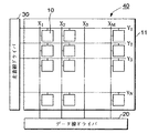
図4は電気光学装置40の主要部分におけるブロック図である。ここでは、電気光学装置40として、アクティブマトリクス駆動型有機ELディスプレイを例示して説明する。電気光学装置40は、透明ガラス基板上にN行M列のマトリクス状に配置された画素回路10を含むアレイ基板11と、同基板上に形成されたM本のデータ線線X1,X2,…,XMを介して列方向に並ぶ画素回路群にプログラミング電流を供給するデータ線ドライバ20と、同基板上に形成されたN本の走査線線Y1,Y2,…,YNを介して行方向に並ぶ画素回路群を線順次走査し、プログラミング電流の供給を選択的にアクティブにする走査線ドライバ30とを備えて構成されている。
【0056】
尚、データ線はソース線と、データ線ドライバはソースドライバと、走査線はゲート線と、走査線ドライバはゲートドライバと、画素回路は単位回路或いは単に画素と称することもできる。
【0057】
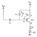
図1はアレイ基板11上において、n行m列(1≦n≦N,1≦m≦M)の位置に配置されている画素回路10の回路構成図である。画素回路10は電流駆動型発光素子として機能する有機EL素子12と、走査線YNから出力される信号を受けてスイッチング動作を行うスイッチングトランジスタTr1〜Tr4と、外部回路からプログラミング電流の供給を受けて所定量の電荷を蓄積する保持キャパシタCrと、保持キャパシタCrから電圧供給を受けて1フレーム期間にわたり有機EL素子12に駆動電流Idを供給する駆動トランジスタTr5と、可変電圧源Vddからの電圧供給を容量カップリングにより駆動トランジスタTr5のゲート電極に伝達し、有機EL素子12への駆動電流Idの供給を制御するキャパシタCsとを含んで構成されている。また、データ線Xmは定電流源21に接続しており、走査線YNは4本のサブ走査線S1〜S4から構成されている。定電流源21から出力される電流はデータ信号とも称され、その電流値は各画素回路10の発光階調に対応して定めれる。
【0058】
上記の構成において、サブ走査線S1〜S4の各々はスイッチングトランジスタTr1〜Tr4のゲート電極に接続しており、Yドライバ30から出力される信号のHレベル/Lレベルに対応してスイッチングトランジスタTr1〜Tr4のオン/オフ制御を行う。スイッチングトランジスタTr1〜Tr4はnチャンネル型FETから構成されており、Hレベルの信号によりオン状態(開状態)となる。スイッチングトランジスタTr1はサブ走査線S1からの信号に対応して、可変電圧源Vddからの電圧をキャパシタCsに供給するためのスイッチング素子であり、そのドレイン端子は可変電圧源Vddに接続される一方、ソース端子はキャパシタCsに接続している。スイッチングトランジスタTr2及びTr4はサブ走査線S2、S4からのHレベルの信号によりオン状態となり、データ線Xmを介して定電流電源22から供給されるプログラミング電流Idatの値に対応した電荷を保持キャパシタCrに蓄積するためのスイッチング素子である。保持キャパシタCrはプログラミング電流Idatの値に対応した電荷を保持するため、記憶キャパシタと称することもできる。スイッチングトランジスタTr2のドレイン端子はキャパシタCs、保持キャパシタCr及び駆動トランジスタTr5のゲート端子に接続される一方、ソース端子はスイッチングトランジスタTr4及びTr3のドレイン端子に接続されている。スイッチングトランジスタTr3はサブ走査線S3からのHレベルの信号によりオン状態となり、駆動トランジスタTr5から出力される駆動電流Idを有機EL素子12に注入するためのスイッチング素子であり、そのソース端子は有機EL素子12の陽極に直列接続される一方、そのドレイン端子は駆動トランジスタTr5のドレイン端子とTr2のソース端子に接続されている。駆動トランジスタTr5はpチャンネル型FETから構成され、そのソース端子は定電圧電源Vccに接続されている。定電圧電源Vccは駆動トランジスタTr5をピンチオフ領域で動作させるために必要かつ十分なバイアス電圧に設定されている。
【0059】
尚、スイッチングトランジスタTr1〜Tr4は、リーク電流が多いと不必要なときに画素が点灯する可能性があるため、オフ状態におけるリーク電流が少ないことが要求される。オフ・リークはLDD構造によって抑えることができるが、pチャネル型FETよりもnチャネル型FETの方がその効果が大きい。よって、スイッチングトランジスタTr1〜Tr4はnチャネル型、駆動トランジスタTr5はpチャネル型が好ましいが、この組み合わせに限られるものではない。
【0060】
図5は画素回路10を駆動するための1フレーム期間内における各信号のタイミングチャートである。1フレーム期間は画素回路10への電流プログラムを行うプログラミング期間と、有機EL素子12へ駆動電流Idを供給する発光期間と、有機EL素子への駆動電流Idの供給を停止する非発光期間とを含む。毎秒60フレームの画像を表示する場合には、1フレーム期間は約16.7msである。プログラミング期間においては、サブ走査線S1,S3の信号がLレベルに立ち下がる一方で、サブ走査線S2,S4の信号がHレベルに立ち上がる。これにより、スイッチングトランジスタTr1,Tr3はオフ状態(閉状態)になる一方、スイッチングトランジスタTr2,Tr4はオン状態となる。また、定電流電源22からは画素回路10に対してプログラミング電流Idatの供給を開始する。このときの画素回路10における等価回路は図2のようになる。
【0061】
同図において、駆動トランジスタTr5のゲート/ソース間の電圧Vgsは当初、負にバイアスされており、そのチャネルに流れる過渡的なドレイン電流は定電流電源21から供給されるプログラミング電流Idatと、ゲート電極に回り込む電流Igの和となる。プログラミング電流Idatの値は表示階調に対応してその大きさが定められるが、本実施形態においては、画素回路10へのデータの書き込み遅延をできるだけ低減するため、プログラミング電流Idatの値をやや大きめに設定している。ゲート電極に回り込む電流Igによって保持キャパシタCrには電荷が蓄積されることになるが、その電荷量(若しくは電圧値)はプログラミング電流Idatに応じた値となる。本実施形態においては、電流プログラミングを通じて保持キャパシタCrに蓄積された電圧によって、駆動トランジスタTr5のゲート端子に印加される初期電圧が定まるため、保持キャパシタCrは電流−電圧変換手段として機能する。このように、電流プログラミングによって保持キャパシタCrに所定の電荷を蓄積する操作をデータの書き込みと称する。スイッチングトランジスタTr2がオン状態となることで、駆動トランジスタTr5のゲート/ドレイン間は導通状態にあるため、プログラミング終了時点において、ゲート/ソース間の電圧Vgsと、ドレイン/ソース間の電圧Vdsとは等しくなっている。
【0062】
保持キャパシタCrへのデータの書き込みが終了したならば、発光期間に入り、サブ走査線S1,S3の信号をLレベルからHレベルに立ち上げる一方で、サブ走査線S2,S4の信号をHレベルからLレベルに立ち下げる。これにより、スイッチングトランジスタTr1,Tr3はオフ状態からオン状態に遷移する一方、スイッチングトランジスタTr2,Tr4はオン状態からオフ状態へ遷移する。また、同期間において定電流電源21から画素回路10に供給されるプログラミング電流Idatは0に停止され、可変電圧源Vddの出力電圧は一定のまま保持される。このときの画素回路10における等価回路は図3のようになる。同図において、電流プログラミングの際に保持キャパシタCrに充電された電圧によって、駆動トランジスタTr5がオン状態となり、同トランジスタから駆動電流が出力される。このときの駆動電流の値は、プログラミング電流Idatにほぼ等しい。従って、発光期間において駆動トランジスタTr5が有機EL素子12を駆動するための駆動電流Idはプログラミング電流Idatにほぼ等しくなる。本実施形態においては、プログラミング電流Idatの値を通常の値よりもやや大きめに設定してあるため、発光期間は通常の値よりもやや短めに設定する必要がある。
【0063】
階調表示に必要な期間、有機EL素子12を駆動したならば、非発光期間に移る。非発光期間においては、可変電圧源Vddの電圧をΔVddだけ変化させる一方で、サブ走査線S1〜S4に出力される各々の信号のオン/オフ状態を維持したままにする。可変電圧源Vddの電圧をΔVddだけ変化させると、キャパシタCsの容量カップリングによりキャパシタ電圧Vrの電圧値が変化し、駆動トランジスタTr5が出力する駆動電流Idの値を制御することができる。つまり、キャパシタCsは駆動トランジスタTr5のゲート端子の電圧を調整するための電圧調整手段として機能する。いま、同図に示す向きにキャパシタ電圧Vrの向きを定めると、キャパシタ電圧Vrは下式のように記述できる。
Vr=Vcc―Vth―CS・ΔVdd/(Cs+Cr+Cg) …(1)
一方、駆動トランジスタTr5のチャネルを流れる駆動電流Idは下式のように記述できることが知られている。
Id=α(Vgs−Vth)2 …(2)
ここで、α=(WμCox)/(2L)であり、Wはチャネル幅、Lはチャネル長、μは移動度、Coxは単位面積当たりのゲート酸化膜容量、Vgsはゲート/ソース間の電圧であり、その向きは同図に示す通りである。Vr=−Vgsであるから、(2)式に(1)式を代入することにより、Vgsを消去し、β=Cs/(Cs+Cr+Cg)とすれば、下式が得られる。
Id=α(βΔVdd−Vcc)2 …(3)
ここで、ΔVdd=Vcc/βとすれば、駆動電流Idを0にすることができ、有機EL素子12の発光を停止することができる。つまり、発光期間においては、ΔVdd=0とする一方、非発光期間においては、ΔVdd=Vcc/βとすることで、駆動トランジスタTr5による駆動電流Idの供給をオン/オフ制御することができる。
【0064】
このように、本実施形態によれば、プログラミング電流Idatの値をやや大きめに設定することで、データの書き込み遅延を低減することができる。さらに、有機EL素子12への駆動電流Idの供給停止は容量カップリングを用いて制御するため、駆動電流Idの供給停止を速やかに行うことができる。駆動電流Idの供給を停止するための他の手段として、例えば、保持キャパシタCrの蓄積電荷を引き抜くための電流経路を別途設け、かかる電流経路から当該蓄積電荷を引き抜けば、駆動トランジスタTr5のゲート電極に印加される電圧を調整できるため、駆動電流Idの供給を停止することができるが、電荷の引き抜きに時間を要するため、高速動作に不向きというデメリットがある。これに対し、容量カップリングを利用すれば、駆動トランジスタTr5のゲート電圧を瞬時に制御できるため、高速動作に優れているというメリットがある。
発明の実施の形態2.
図6は第2の実施形態における画素回路10の回路構成図である。同図において、トランジスタTr5及びTr6は各々のゲート電極同士及びソース電極同士が相互に接続しており、カレントミラー回路を構成している。カレントミラー回路においては、各々のトランジスタを流れる電流比は利得係数の比に等しい。このため、トランジスタTr5及びTr6のチャネル長、チャネル幅、ゲート酸化膜容量等のデバイスパラメータを適当に設計することで、両者の電流比をk:1とすることができる。図中、スイッチングトランジスタTr1〜Tr4、キャパシタCs、及び保持キャパシタCrの各々の動作は実施形態1と同様であり、詳細な説明は省略する。また、トランジスタTr5及びTr6はpチャンネル型FETである。上記の構成において、プログラミング期間における画素回路10の等価回路は図2と同じ構成になり、発光期間及び非発光期間における画素回路10の等価回路は図3と同じ構成になる(但し、本実施形態においては、図3に記載のトランジスタTr5をトランジスタTr6に置き換えた構成となる。)。ここで、k>1となるようにトランジスタTr5及びTr6の利得係数を設定すれば、プログラミング期間におけるトランジスタTr5による保持キャパシタCrへの電荷の蓄積を高速に行うことができ、プログラミング期間を短縮することができる。
【0065】
尚、上記の説明では、データ信号の供給を線順次操作で行っていたが、これに限らず、例えば、点順次走査或いは相展開方式で行ってもよい。また、上述のトランジスタTr1〜Tr6の全部又は一部について、FETに替えてバイポーラトランジスタや、他のスイッチング素子で代用してもよい。また、上記の例では、アクティブマトリクス駆動方式を前提に説明したが、これに限らず、パッシブマトリクス駆動方式を利用してもよい。また、上記の説明では有機ELディスプレイの例を説明したが、LEDや、FEDなどの電流駆動型発光素子を用いた電気光学装置にも適用できる。
【0066】
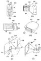
図7に本発明の電気光学装置40を適用可能な電子機器の例を挙げる。同図(a)は携帯電話への適用例であり、携帯電話230は、アンテナ部231、音声出力部232、音声入力部233、操作部234、及び本発明の電気光学装置40を備えている。このように本発明の電気光学装置40を携帯電話230の表示部として利用可能である。同図(b)はビデオカメラへの適用例であり、ビデオカメラ240は、受像部241、操作部242、音声入力部243、及び本発明の電気光学装置40を備えている。このように本発明の電気光学装置は、ファインダーや表示部として利用可能である。同図(c)は携帯型パーソナルコンピュータへの適用例であり、コンピュータ250は、カメラ部251、操作部252、及び本発明の電気光学装置40を備えている。このように本発明の電気光学装置は、表示部として利用可能である。
【0067】
同図(d)はヘッドマウントディスプレイへの適用例であり、ヘッドマウントディスプレイ260は、バンド261、光学系収納部262及び本発明の電気光学装置40を備えている。このように本発明の電気光学装置は画像表示源として利用可能である。同図(e)はリア型プロジェクターへの適用例であり、プロジェクター270は、筐体271に、光源272、合成光学系273、ミラー274、ミラー275、スクリーン276、及び本発明の電気光学装置40を備えている。このように本発明の電気光学装置は画像表示源として利用可能である。同図(f)はフロント型プロジェクターへの適用例であり、プロジェクター280は、筐体282に光学系281及び本発明の電気光学装置40を備え、画像をスクリーン283に表示可能になっている。このように本発明の電気光学装置は画像表示源として利用可能である。上記例に限らず本発明の電気光学装置40は、アクティブマトリクス型の表示装置を適用可能なあらゆる電子機器に適用可能である。例えば、この他に、表示機能付きファックス装置、デジタルカメラのファインダ、携帯型TV、DSP装置、PDA、電子手帳、電光掲示盤、宣伝公告用ディスプレイ、POS端末、ワークステーション、テレビ電話、ワードプロセッサ、電卓、ページャ、カーナビゲーション装置などに備えられている電気光学装置にも適用可能である。
【0068】
【発明の効果】
本発明によれば、トランジスタのゲート端子の電圧を容量カップリングを用いて制御することによって、電子素子へ供給される電流の出力を瞬時に制御できるため、電子回路の高速駆動を可能にすることができる。
【図面の簡単な説明】
【図1】実施形態1に係わる画素回路の回路構成図である。
【図2】電流プログラミング時における画素回路の等価回路である。
【図3】発光期間における画素回路の等価回路である。
【図4】有機ELディスプレイの主要回路構成図である。
【図5】画素回路を駆動するための各信号のタイミングチャートである。
【図6】実施形態2に係わる画素回路の回路構成図である。
【図7】電気光学装置を備えた電子機器の例である。
【符号の説明】
10…画素回路
11…アレイ基板
20…データ線ドライバ
21…定電流源
30…走査線ドライバ
Tr1〜Tr4…スイッチングトランジスタ
Tr5…駆動トランジスタ
Cr…保持キャパシタ
Cs…キャパシタ[0001]
BACKGROUND OF THE INVENTION
The present invention relates to a drive control technique for an electronic device.
[0002]
[Prior art]
In the method of setting the amount of current to be supplied to the organic EL element by controlling the conduction state of the transistor by applying a voltage according to the data signal to the gate terminal, it is affected by variations such as the threshold voltage of the transistor. In general, a thin film transistor for driving each organic EL element is used to drive a display device including a large number of organic EL elements. However, since the variation in characteristics of the thin film transistor is significant compared to a silicon-based transistor, It is difficult to accurately supply a current amount for obtaining an intermediate gradation to an organic EL element. As a method for compensating for such variations in transistor characteristics, a current programming method has been proposed.
[0003]
In the current programming method, the amount of charge corresponding to the current (programming current) supplied from the current output circuit is held in the holding capacitor according to the light emission gradation, and the forward bias current (drive current) supplied to the organic EL element is supplied. In this method, the gate terminal of the driving transistor is controlled by the voltage charged in the holding capacitor. Therefore, the variation in characteristics such as the threshold voltage of the transistor is compensated, and the driving current is almost the same as the programming current value. The organic EL element can be driven. As described above, a series of operations for setting the light emission gradation according to the current value is referred to as “current programming”.
[0004]
[Problems to be solved by the invention]
However, in the current programming method, current is used to accumulate charges in the holding capacitor. Therefore, if programming is performed with a small current, there is a problem that programming takes time due to the influence of wiring capacitance.
[0005]
SUMMARY OF THE INVENTION It is an object of the present invention to propose an electronic circuit and a driving method thereof, an electronic device, an electro-optical device, and an electronic device that can reduce data writing delay at a low gradation level and enable high-speed driving of a pixel circuit. And
[0006]
[Means for Solving the Problems]
An electronic circuit according to the present invention converts an electronic element, a first transistor that controls a current amount supplied to the electronic element according to a conduction state, and a programming current that passes through at least the first transistor into a voltage. Current-voltage conversion means for performing current-voltage conversion for setting the voltage value applied to the first gate terminal of the first transistor to the first voltage value, and the first gate terminal Voltage adjusting means for changing the applied voltage value from the first voltage value to the second voltage value set so as to reduce the conduction state of the first transistor in comparison with the first voltage value. And the voltage adjusting means includes a capacitor and a second transistor connected between the capacitor and the voltage source, and the capacitor and the voltage via the second transistor. Source and By being electrically connected, the voltage applied to the first gate terminal, that changes from the first voltage value to the second voltage value, characterized by.
An electronic circuit according to the present invention includes an electronic element, a first transistor connected in series to the electronic element, a capacitive element, a second transistor connected between the capacitive element and a voltage source, In the first period, the voltage value applied to the first gate terminal of the first transistor is set to the first voltage value, and in the second period via the second transistor When the capacitive element and the voltage source are electrically connected, the voltage value applied to the first gate terminal is higher than the first voltage value from the first voltage value. It changes to the 2nd voltage value set so that the said conduction | electrical_connection state of 1 transistor might be reduced, It is characterized by the above-mentioned.
The programming current is set based on a data signal.
The electronic element is an electro-optical element.
The capacitive element includes a first electrode and a second electrode, the first electrode is connected to the first gate terminal, and the second electrode is connected to the second transistor. ing.
An electronic device according to the present invention includes the electronic circuit.
An electronic circuit driving method according to the present invention includes an electronic element, a first transistor connected in series to the electronic element, a capacitive element, and a second transistor connected between the capacitive element and a voltage source. A voltage value applied to a first gate terminal of the first transistor in a first period, and a second voltage value for the second circuit. In this period, by electrically connecting the capacitive element and the voltage source through the second transistor, the voltage value applied to the first gate terminal is changed from the first voltage value to the voltage source. The first voltage value is changed to a second voltage value set so as to reduce the conduction state of the first transistor compared to the first voltage value.
The capacitor element includes a first electrode and a second electrode, and the second electrode and the voltage source are electrically connected through the second transistor in the second period. The
The electronic element is an electro-optical element.
In order to solve the above problems, an electronic circuit according to the present invention includes a transistor that supplies a current to an electronic element, and a charge holding unit that holds a charge amount corresponding to a voltage value applied to the gate terminal of the transistor. The charge holding means includes a first capacitive element, and the first capacitive element is connectable to a variable voltage supply means.
[0007]
With this configuration, the conduction state of the transistor can be controlled by transmitting the voltage change supplied from the variable voltage supply unit to the gate terminal via the first capacitor element.
[0008]
Here, “charge holding means” refers to general circuit elements having a charge storage function, and is not particularly limited.
[0009]
“Variable voltage supply means” means means for supplying a variable voltage. In addition to a variable voltage source that can arbitrarily vary the supply voltage level, the power output of a plurality of voltage sources with different voltage levels can be switched. This also includes the case of switching output via.
[0010]
“Electronic element” means a general circuit element constituting an electronic circuit, and is not particularly limited.
[0011]
Preferably, the first capacitive element controls the conduction state of the transistor by transmitting a voltage change supplied from the variable voltage supply means to the gate terminal.
[0012]
By transmitting the voltage change of the variable voltage supply means to the gate terminal via the capacitive coupling, it becomes possible to quickly control the potential change of the gate terminal.
[0013]
Preferably, one electrode of the first capacitive element is connected to the gate terminal of the transistor, and the other electrode is connectable to the variable voltage supply means via at least one switching element.
[0014]
With this configuration, a voltage change from the variable voltage supply means can be transmitted to the capacitive element via the switching element.
[0015]
Preferably, the charge holding unit further includes a second capacitor element, one electrode of the second capacitor element is connected to the gate terminal, and the other electrode is connectable to a power supply line.
[0016]
With such a structure, the voltage of the gate terminal of the transistor can be adjusted by the voltage accumulated in the second capacitor.
[0017]
Preferably, the transistor can be connected to a current output circuit via at least one switching element.
[0018]
Here, the current output circuit refers to a current source whose output current value is determined corresponding to a data signal. Taking a current-driven light emitting element such as an organic EL element as an example of the electronic element, the data signal corresponds to a light emission gradation.
[0019]
Preferably, the second capacitive element holds a charge corresponding to an output current that passes through the transistor and is output from the current output circuit, while the same as the output current from a drain terminal or a source terminal of the transistor. The voltage applied to the gate terminal is adjusted in order to output a current of a certain degree.
[0020]
For example, an electro-optical element is preferable as the electronic element, and a current-driven light-emitting element is particularly preferable. An electro-optical element generally refers to an element that emits light by an electric action or changes an optical state of light supplied from the outside, and includes a liquid crystal element, an electrophoretic element, an electroluminescent element, an electron-emitting element, and the like. Including. The current-driven light-emitting element refers to an element that emits light when supplied with an external current, and corresponds to an electroluminescent element.
[0021]
Preferably, the value of the output current is set corresponding to the light emission gradation of the electronic element. The display gradation can be controlled by setting the value of the output current from the current output circuit corresponding to the light emission gradation.
[0022]
An electronic circuit according to the present invention includes an electronic element, a transistor that controls an amount of current supplied to the electronic element according to a conduction state, a current that passes through the transistor at least is converted into a voltage, and a gate terminal of the transistor Current-voltage converting means for performing current-voltage conversion for setting an initial value of the voltage value applied to the voltage, and voltage adjusting means for adjusting the voltage value applied to the gate terminal after the current-voltage conversion With.
[0023]
With this configuration, current supply from the transistor to the electronic element can be promoted by the current-voltage conversion means, while the conduction state of the transistor can be controlled by the voltage adjustment means to adjust the amount of current supplied to the electronic element. .
[0024]
Here, “current-voltage conversion means” refers to general circuit elements for converting a current signal that has passed through a transistor into a voltage signal for driving the transistor.
[0025]
“Voltage adjusting means” refers to general circuit elements for adjusting the voltage at the gate terminal of a transistor.
[0026]
Preferably, the current passing through the transistor during the current-voltage conversion is a current value set based on a data signal.
[0027]
Preferably, the voltage adjusting unit adjusts a voltage value applied to a gate terminal of the transistor so as to reduce a conduction state of the transistor during the current-voltage conversion.
[0028]
Preferably, the voltage adjusting unit applies a voltage change supplied from the variable voltage supply unit to the gate terminal through capacitive coupling to control the conduction state of the transistor.
[0029]
Examples of the electronic element include an electro-optical element, a current-driven light emitting element, and an organic EL element.
[0030]
The electronic device of the present invention includes the electronic circuit of the present invention.
[0031]
Here, the “electronic device” is not particularly limited, but generally refers to a device including the electronic circuit of the present invention as a circuit element.
[0032]
The electro-optical device of the present invention is an electro-optical device including a plurality of unit circuits arranged corresponding to intersections of a plurality of data lines and a plurality of scanning lines, and the electro-optical device includes the plurality of data lines via the plurality of data lines. A data line driving circuit for controlling transmission of a data signal to be supplied to the unit circuit; and a scanning line driving circuit for controlling transmission of a scanning signal to be supplied to the unit circuit via the plurality of scanning lines. Comprises an electro-optical element, a driving transistor for supplying a driving current to the electro-optical element, and a charge holding unit having at least a function of holding the data signal supplied to the unit circuit as a charge amount. The holding means includes a first capacitive element, one electrode of the first capacitive element is connected to the gate terminal of the driving transistor, and the other electrode is connectable to the variable voltage supply means.
[0033]
With this configuration, the current supplied from the data line driving circuit to the unit circuit is held by charge retention, and the supply of the driving current supplied from the transistor to the electro-optical element is urged, while being variable via the first capacitor element. By changing the voltage supplied from the voltage supply means to the gate terminal, the conduction state of the transistor can be controlled, and the amount of drive current supplied to the electro-optical element can be controlled.
[0034]
Here, the “electro-optical device” refers to a display device for generating a display image by emitting light by an electric action or changing an optical state of light supplied from the outside.
[0035]
Preferably, a change in the value of the voltage output from the variable voltage supply means can be transmitted to the gate terminal via the first capacitive element.
[0036]
Preferably, the first capacitive element can be connected to the variable voltage supply means via at least one switching element.
[0037]
Preferably, the charge holding means further includes a second capacitor element, one electrode of the second capacitor element is connected to the gate terminal, and the other electrode is connectable to a power supply line.
[0038]
Preferably, the transistor can be connected to the data line driving circuit via at least one switching element.
[0039]
Preferably, the second capacitor element holds a charge corresponding to an output current that passes through the transistor and is output from the data line driver circuit, while the output current from the drain terminal or the source terminal of the transistor. In order to output the same level of current, the voltage applied to the gate terminal is adjusted.
[0040]
Preferably, a current output circuit for outputting a current as the data signal is provided.
[0041]
Examples of the electronic element include an electro-optical element, a current-driven light emitting element, and an organic EL element.
[0042]
The electro-optical device of the present invention is an electro-optical device including a plurality of unit circuits arranged corresponding to intersections of a plurality of data lines and a plurality of scanning lines, and the electro-optical device includes the plurality of data lines via the plurality of data lines. A data line driving circuit for controlling transmission of a data signal to be supplied to the unit circuit; and a scanning line driving circuit for controlling transmission of a scanning signal to be supplied to the unit circuit via the plurality of scanning lines. Is a voltage that is applied to the gate terminal of the transistor by converting an electronic element, a transistor that controls the amount of current supplied to the electronic element in accordance with a conduction state, and at least a current that passes through the transistor into a voltage. Current-voltage conversion means for performing current-voltage conversion for setting an initial value of the value, and voltage adjustment means for adjusting a voltage value applied to the gate terminal after the current-voltage conversion Equipped with a.
[0043]
Preferably, the current passing through the transistor during the current-voltage conversion is a current value set based on the data signal.
[0044]
Preferably, the voltage adjusting unit adjusts a voltage value applied to a gate terminal of the transistor so as to reduce a conduction state of the transistor during the current-voltage conversion.
[0045]
Preferably, the voltage adjusting unit applies a voltage change supplied from the variable voltage supply unit to the gate terminal through capacitive coupling to control the conduction state of the transistor.
[0046]
Examples of the electronic element include an electro-optical element, a current-driven light emitting element, and an organic EL element.
[0047]
The electronic apparatus according to the present invention includes the electro-optical device according to the present invention.
[0048]
Such an electronic apparatus is not particularly limited as long as it is an apparatus including an electro-optical device as a display. A mobile phone, a video camera, a personal computer, a head-mounted display, a projector, a fax machine, a digital camera, a PDA, an electronic device Includes notebooks.
[0049]
According to the electronic circuit driving method of the present invention, the data signal supplied through the data line is passed between the drain terminal and the source terminal of the transistor with one electrode of the holding capacitor connected to the gate terminal of the transistor. A storage step of accumulating electric charge in the holding capacitor and converting the data signal to an initial value of a voltage to be applied to the gate terminal; and an applied voltage of the gate terminal by the voltage charged in the holding capacitor. An adjustment step for supplying a current output from the transistor to the electronic element; and an adjustment for transmitting a voltage change of the variable voltage supply means to the gate terminal via a capacitive coupling to adjust a conduction state of the transistor. Steps.
[0050]
Preferably, the data signal is a current.
[0051]
Preferably, in the adjustment step, the voltage change from the variable voltage supply means is supplied to the other electrode of the capacitive element connected to one electrode of the gate terminal.
[0052]
Examples of the electronic element include an electro-optical element, a current-driven light emitting element, and an organic EL element.
[0053]
Preferably, in the adjustment step, after the light emission period corresponding to the display gradation has elapsed, the conduction state of the transistor is adjusted to be off.
[0054]
DETAILED DESCRIPTION OF THE INVENTION
Embodiment 1 of the Invention
Hereinafter, the present embodiment will be described with reference to the drawings.
[0055]
FIG. 4 is a block diagram of the main part of the electro-
[0056]
The data line can also be called a source line, the data line driver can be called a source driver, the scanning line can be called a gate line, the scanning line driver can be called a gate driver, and the pixel circuit can be called a unit circuit or simply a pixel.
[0057]
FIG. 1 is a circuit configuration diagram of a
[0058]
In the above configuration, each of the sub scanning lines S1 to S4 is connected to the gate electrodes of the switching transistors Tr1 to Tr4, and the switching transistors Tr1 to Tr4 correspond to the H level / L level of the signal output from the
[0059]
Note that the switching transistors Tr1 to Tr4 are required to have a small leakage current in an off state because a pixel may be lit when it is unnecessary if a large leakage current is present. Off-leakage can be suppressed by the LDD structure, but an n-channel FET is more effective than a p-channel FET. Therefore, the switching transistors Tr1 to Tr4 are preferably n-channel type and the driving transistor Tr5 is preferably p-channel type, but the combination is not limited to this.
[0060]
FIG. 5 is a timing chart of signals in one frame period for driving the
[0061]
In the figure, the gate-source voltage V gs of the driving transistor Tr5 is initially negatively biased, and the transient drain current flowing through the channel is represented by the programming current I dat supplied from the constant
[0062]
When the writing of data to the holding capacitor Cr is completed, the light emission period starts, and the signals of the sub-scan lines S1 and S3 are raised from the L level to the H level, while the signals of the sub-scan lines S2 and S4 are set to the H level. Falls to L level. Thereby, the switching transistors Tr1 and Tr3 transition from the off state to the on state, while the switching transistors Tr2 and Tr4 transition from the on state to the off state. In addition, the programming current I dat supplied from the constant
[0063]
If the
V r = V cc -V th -C S · ΔV dd / (C s + C r + C g) ... (1)
On the other hand, it is known that the drive current I d flowing through the channel of the drive transistor Tr5 can be described by the following equation.
I d = α (V gs −V th ) 2 (2)
Here, α = (WμC ox ) / (2L), W is the channel width, L is the channel length, μ is the mobility, C ox is the gate oxide film capacity per unit area, and V gs is between the gate and the source. The direction is as shown in FIG. Since V r = −V gs , by substituting equation (1) into equation (2), V gs is eliminated, and β = C s / (C s + C r + C g ) Is obtained.
I d = α (βΔV dd −V cc ) 2 (3)
Here, if ΔV dd = V cc / β, the drive current I d can be set to 0, and the light emission of the
[0064]
Thus, according to the present embodiment, the data write delay can be reduced by setting the programming current I dat to be slightly larger. Furthermore, since the supply stop of the drive current I d to the
FIG. 6 is a circuit configuration diagram of the
[0065]
In the above description, the data signal is supplied by line sequential operation. However, the present invention is not limited to this. For example, the data signal may be supplied by dot sequential scanning or phase expansion. Further, all or part of the above-described transistors Tr1 to Tr6 may be replaced with a bipolar transistor or another switching element instead of the FET. In the above example, the active matrix driving method has been described. However, the present invention is not limited to this, and a passive matrix driving method may be used. In the above description, an example of an organic EL display has been described. However, the present invention can also be applied to an electro-optical device using an LED or a current-driven light emitting element such as an FED.
[0066]
FIG. 7 shows an example of an electronic apparatus to which the electro-
[0067]
FIG. 4D shows an application example to a head mounted display. The head mounted
[0068]
【The invention's effect】
According to the present invention, since the output of the current supplied to the electronic element can be instantaneously controlled by controlling the voltage at the gate terminal of the transistor using capacitive coupling, the electronic circuit can be driven at high speed. Can do.
[Brief description of the drawings]
FIG. 1 is a circuit configuration diagram of a pixel circuit according to a first embodiment.
FIG. 2 is an equivalent circuit of a pixel circuit during current programming.
FIG. 3 is an equivalent circuit of a pixel circuit in a light emission period.
FIG. 4 is a main circuit configuration diagram of an organic EL display.
FIG. 5 is a timing chart of signals for driving a pixel circuit.
6 is a circuit configuration diagram of a pixel circuit according to
FIG. 7 is an example of an electronic apparatus including an electro-optical device.
[Explanation of symbols]
DESCRIPTION OF
Claims (9)
前記電子素子に供給する電流量を導通状態に応じて制御する第1のトランジスタと、
少なくとも前記第1のトランジスタを通過するプログラミング電流を電圧に変換して、前記第1のトランジスタの第1のゲート端子に印加される電圧値を第1の電圧値に設定するための電流−電圧変換を行う電流−電圧変換手段と、
前記第1のゲート端子に印加される電圧値を前記第1の電圧値から前記第1の電圧値に比して前記第1のトランジスタの前記導通状態を減ずるように設定された第2の電圧値に変化させる電圧調整手段と、を備え、
前記電圧調整手段は、容量素子と前記容量素子と電圧源との間に接続された第2のトランジスタと、を含み、
前記第2のトランジスタを介して前記容量素子と前記電圧源とが電気的に接続されることにより、前記第1のゲート端子に印加される電圧値は、前記第1の電圧値から前記第2の電圧値に変化すること、
を特徴とする電子回路。An electronic element;
A first transistor that controls an amount of current supplied to the electronic element according to a conduction state;
Current-voltage conversion for converting a programming current passing through at least the first transistor into a voltage and setting a voltage value applied to a first gate terminal of the first transistor to a first voltage value Current-voltage conversion means for performing
A second voltage set to reduce the conduction state of the first transistor by comparing a voltage value applied to the first gate terminal from the first voltage value to the first voltage value. Voltage adjusting means for changing to a value,
The voltage adjusting means includes a capacitive element and a second transistor connected between the capacitive element and a voltage source,
When the capacitive element and the voltage source are electrically connected via the second transistor, the voltage value applied to the first gate terminal is changed from the first voltage value to the second voltage value. Change to the voltage value of
An electronic circuit characterized by
前記電子素子に直列に接続された第1のトランジスタと、
容量素子と、
前記容量素子と電圧源との間に接続された第2のトランジスタと、を備え、
第1の期間において、前記第1のトランジスタの第1のゲート端子に印加される電圧値は第1の電圧値に設定され、
第2の期間において、前記第2のトランジスタを介して前記容量素子と前記電圧源とが電気的に接続されることにより、前記第1のゲート端子に印加される電圧値は前記第1の電圧値から前記第1の電圧値に比して前記第1のトランジスタの前記導通状態を減ずるように設定された第2の電圧値に変化すること、
を特徴とする電子回路。An electronic element;
A first transistor connected in series to the electronic element;
A capacitive element;
A second transistor connected between the capacitive element and a voltage source,
In the first period, the voltage value applied to the first gate terminal of the first transistor is set to the first voltage value;
In the second period, the capacitance element and the voltage source are electrically connected via the second transistor, whereby the voltage value applied to the first gate terminal is the first voltage. Changing from a value to a second voltage value set to reduce the conduction state of the first transistor relative to the first voltage value;
An electronic circuit characterized by
前記プログラミング電流はデータ信号に基づいて設定されること、
を特徴とする電子回路。The electronic circuit according to claim 1 or 2 ,
The programming current is set based on a data signal;
An electronic circuit characterized by
前記電子素子は電気光学素子であること、
を特徴とする電子回路。The electronic circuit according to any one of claims 1 to 3 ,
The electronic element is an electro-optical element;
An electronic circuit characterized by
前記容量素子は、第1の電極と第2の電極とを含み、
前記第1の電極は、前記第1のゲート端子に接続され、
前記第2の電極は、前記第2のトランジスタに接続されていること、
を特徴とする電子回路。The electronic circuit according to any one of claims 1 to 4 ,
The capacitive element includes a first electrode and a second electrode,
The first electrode is connected to the first gate terminal;
The second electrode is connected to the second transistor;
An electronic circuit characterized by
第1の期間において、前記第1のトランジスタの第1のゲート端子に印加される電圧値を第1の電圧値に設定し、
第2の期間において、前記第2のトランジスタを介して前記容量素子と前記電圧源とを電気的に接続することにより、前記第1のゲート端子に印加される電圧値を前記第1の電圧値から前記第1の電圧値に比して前記第1のトランジスタの前記導通状態を減ずるように設定された第2の電圧値に変化させること、
を特徴とする電子回路の駆動方法。An electronic circuit driving method comprising: an electronic element; a first transistor connected in series to the electronic element; a capacitive element; and a second transistor connected between the capacitive element and a voltage source. Because
In the first period, the voltage value applied to the first gate terminal of the first transistor is set to the first voltage value,
In the second period, by electrically connecting the capacitive element and the voltage source through the second transistor, the voltage value applied to the first gate terminal is changed to the first voltage value. To a second voltage value set to reduce the conduction state of the first transistor relative to the first voltage value;
An electronic circuit driving method characterized by the above.
前記容量素子は、第1の電極と第2の電極とを有し、
前記第2の期間において、前記第2のトランジスタを介して前記第2の電極と前記電圧源とが電気的に接続されること、
を特徴とする電子回路の駆動方法。The method for driving an electronic circuit according to claim 7 ,
The capacitive element has a first electrode and a second electrode,
In the second period, the second electrode and the voltage source are electrically connected through the second transistor;
An electronic circuit driving method characterized by the above.
前記電子素子は電気光学素子であること、
を特徴とする電子回路の駆動方法。The method of driving an electronic circuit according to claim 7 or 8 ,
The electronic element is an electro-optical element;
An electronic circuit driving method characterized by the above.
Priority Applications (1)
| Application Number | Priority Date | Filing Date | Title |
|---|---|---|---|
| JP2002101837A JP4069408B2 (en) | 2002-04-03 | 2002-04-03 | Electronic circuit, driving method thereof, and electronic apparatus |
Applications Claiming Priority (1)
| Application Number | Priority Date | Filing Date | Title |
|---|---|---|---|
| JP2002101837A JP4069408B2 (en) | 2002-04-03 | 2002-04-03 | Electronic circuit, driving method thereof, and electronic apparatus |
Related Child Applications (1)
| Application Number | Title | Priority Date | Filing Date |
|---|---|---|---|
| JP2007128426A Division JP2007264647A (en) | 2007-05-14 | 2007-05-14 | Electronic circuit, electro-optical device, electronic apparatus, and electronic device |
Publications (3)
| Publication Number | Publication Date |
|---|---|
| JP2003295824A JP2003295824A (en) | 2003-10-15 |
| JP2003295824A5 JP2003295824A5 (en) | 2005-09-15 |
| JP4069408B2 true JP4069408B2 (en) | 2008-04-02 |
Family
ID=29241997
Family Applications (1)
| Application Number | Title | Priority Date | Filing Date |
|---|---|---|---|
| JP2002101837A Expired - Fee Related JP4069408B2 (en) | 2002-04-03 | 2002-04-03 | Electronic circuit, driving method thereof, and electronic apparatus |
Country Status (1)
| Country | Link |
|---|---|
| JP (1) | JP4069408B2 (en) |
Cited By (1)
| Publication number | Priority date | Publication date | Assignee | Title |
|---|---|---|---|---|
| CN111462700A (en) * | 2020-04-23 | 2020-07-28 | 湖南鹰神新材料科技有限公司 | Active light-emitting display pixel circuit, display method and active light-emitting display |
Families Citing this family (15)
| Publication number | Priority date | Publication date | Assignee | Title |
|---|---|---|---|---|
| TWI261213B (en) | 2003-08-21 | 2006-09-01 | Seiko Epson Corp | Optoelectronic apparatus and electronic machine |
| JP2005099715A (en) | 2003-08-29 | 2005-04-14 | Seiko Epson Corp | Driving method of electronic circuit, electronic circuit, electronic device, electrooptical device, electronic equipment and driving method of electronic device |
| JP2005099714A (en) | 2003-08-29 | 2005-04-14 | Seiko Epson Corp | Electrooptical device, driving method of electrooptical device, and electronic equipment |
| JP5044883B2 (en) * | 2004-03-31 | 2012-10-10 | 日本電気株式会社 | Display device, electric circuit driving method, and display device driving method |
| JP4660116B2 (en) * | 2004-05-20 | 2011-03-30 | 三洋電機株式会社 | Current-driven pixel circuit |
| JP4834876B2 (en) * | 2004-06-25 | 2011-12-14 | 京セラ株式会社 | Image display device |
| JP5137299B2 (en) * | 2004-08-31 | 2013-02-06 | エルジー ディスプレイ カンパニー リミテッド | Image display device |
| JP2006162773A (en) * | 2004-12-03 | 2006-06-22 | Canon Inc | Current programming device and current programming method |
| KR100752289B1 (en) * | 2004-12-28 | 2007-08-29 | 세이코 엡슨 가부시키가이샤 | Unit circuit, method of controlling unit circuit, electronic device, and electronic apparatus |
| KR100784013B1 (en) | 2006-04-13 | 2007-12-07 | 삼성에스디아이 주식회사 | Pixel Circuit of Organic Light Emitting Display Device and driving method |
| KR100824854B1 (en) | 2006-12-21 | 2008-04-23 | 삼성에스디아이 주식회사 | Organic light emitting display |
| KR100833756B1 (en) | 2007-01-15 | 2008-05-29 | 삼성에스디아이 주식회사 | Organic light emitting display |
| JP5056265B2 (en) | 2007-08-15 | 2012-10-24 | ソニー株式会社 | Display device and electronic device |
| JP2008146051A (en) * | 2007-11-22 | 2008-06-26 | Toshiba Matsushita Display Technology Co Ltd | El display device |
| JP4930799B2 (en) * | 2008-09-08 | 2012-05-16 | セイコーエプソン株式会社 | Electro-optical device and electronic apparatus |
-
2002
- 2002-04-03 JP JP2002101837A patent/JP4069408B2/en not_active Expired - Fee Related
Cited By (2)
| Publication number | Priority date | Publication date | Assignee | Title |
|---|---|---|---|---|
| CN111462700A (en) * | 2020-04-23 | 2020-07-28 | 湖南鹰神新材料科技有限公司 | Active light-emitting display pixel circuit, display method and active light-emitting display |
| CN111462700B (en) * | 2020-04-23 | 2021-06-01 | 湖南鹰神新材料科技有限公司 | Active light-emitting display pixel circuit, display method and active light-emitting display |
Also Published As
| Publication number | Publication date |
|---|---|
| JP2003295824A (en) | 2003-10-15 |
Similar Documents
| Publication | Publication Date | Title |
|---|---|---|
| US11139323B2 (en) | Digital circuit having correcting circuit and electronic apparatus thereof | |
| EP1170718B1 (en) | Current sampling circuit for organic electroluminescent display | |
| JP5106617B2 (en) | Semiconductor device and electronic equipment | |
| JP3972359B2 (en) | Display device | |
| JP5604563B2 (en) | Semiconductor device | |
| JP4069408B2 (en) | Electronic circuit, driving method thereof, and electronic apparatus | |
| US9825624B2 (en) | Semiconductor device and driving method of the same | |
| US20130002642A1 (en) | Display device with power source supply scan circuits and driving method thereof | |
| JP4850303B2 (en) | Semiconductor device | |
| JP4930799B2 (en) | Electro-optical device and electronic apparatus | |
| JP5514389B2 (en) | Semiconductor device and display device | |
| JP3849466B2 (en) | Drive circuit, electro-optical device, drive circuit drive method, organic electroluminescence device, and electronic apparatus | |
| JP2007264647A (en) | Electronic circuit, electro-optical device, electronic apparatus, and electronic device |
Legal Events
| Date | Code | Title | Description |
|---|---|---|---|
| A521 | Request for written amendment filed |
Free format text: JAPANESE INTERMEDIATE CODE: A523 Effective date: 20050325 |
|
| A621 | Written request for application examination |
Free format text: JAPANESE INTERMEDIATE CODE: A621 Effective date: 20050325 |
|
| A131 | Notification of reasons for refusal |
Free format text: JAPANESE INTERMEDIATE CODE: A131 Effective date: 20070315 |
|
| A521 | Request for written amendment filed |
Free format text: JAPANESE INTERMEDIATE CODE: A523 Effective date: 20070514 |
|
| A131 | Notification of reasons for refusal |
Free format text: JAPANESE INTERMEDIATE CODE: A131 Effective date: 20070831 |
|
| A521 | Request for written amendment filed |
Free format text: JAPANESE INTERMEDIATE CODE: A523 Effective date: 20071030 |
|
| TRDD | Decision of grant or rejection written | ||
| A01 | Written decision to grant a patent or to grant a registration (utility model) |
Free format text: JAPANESE INTERMEDIATE CODE: A01 Effective date: 20071220 |
|
| A61 | First payment of annual fees (during grant procedure) |
Free format text: JAPANESE INTERMEDIATE CODE: A61 Effective date: 20080102 |
|
| R150 | Certificate of patent or registration of utility model |
Free format text: JAPANESE INTERMEDIATE CODE: R150 |
|
| FPAY | Renewal fee payment (event date is renewal date of database) |
Free format text: PAYMENT UNTIL: 20110125 Year of fee payment: 3 |
|
| FPAY | Renewal fee payment (event date is renewal date of database) |
Free format text: PAYMENT UNTIL: 20110125 Year of fee payment: 3 |
|
| FPAY | Renewal fee payment (event date is renewal date of database) |
Free format text: PAYMENT UNTIL: 20120125 Year of fee payment: 4 |
|
| FPAY | Renewal fee payment (event date is renewal date of database) |
Free format text: PAYMENT UNTIL: 20120125 Year of fee payment: 4 |
|
| FPAY | Renewal fee payment (event date is renewal date of database) |
Free format text: PAYMENT UNTIL: 20130125 Year of fee payment: 5 |
|
| FPAY | Renewal fee payment (event date is renewal date of database) |
Free format text: PAYMENT UNTIL: 20130125 Year of fee payment: 5 |
|
| FPAY | Renewal fee payment (event date is renewal date of database) |
Free format text: PAYMENT UNTIL: 20140125 Year of fee payment: 6 |
|
| LAPS | Cancellation because of no payment of annual fees |