JP4066131B2 - Cleaning device, inkjet printer, and control method thereof - Google Patents
Cleaning device, inkjet printer, and control method thereof Download PDFInfo
- Publication number
- JP4066131B2 JP4066131B2 JP2001315858A JP2001315858A JP4066131B2 JP 4066131 B2 JP4066131 B2 JP 4066131B2 JP 2001315858 A JP2001315858 A JP 2001315858A JP 2001315858 A JP2001315858 A JP 2001315858A JP 4066131 B2 JP4066131 B2 JP 4066131B2
- Authority
- JP
- Japan
- Prior art keywords
- nozzle
- ink
- defective
- nozzles
- cleaning
- Prior art date
- Legal status (The legal status is an assumption and is not a legal conclusion. Google has not performed a legal analysis and makes no representation as to the accuracy of the status listed.)
- Expired - Fee Related
Links
Images


Description
【0001】
【発明の属する技術分野】
本発明は、インクノズルの目詰まり(ドット抜け)を検出し、クリーニングするクリーニング装置を備えたインクジェットプリンタに関する。
【0002】
【従来の技術】
インクジェットプリンタは、印字ヘッドのインクノズルからインク液滴を吐出することにより、印刷媒体上に所望の印刷を形成する。インクノズルからインク液滴が吐出されない状態が一定時間以上継続すると、インクの溶媒である水分が蒸発してインクノズル近傍のインク粘度が増加し、延いてはインクノズルが目詰まりを起こし、インク液滴が吐出されなかったり、吐出されても本来の大きさやスピードのインク液滴ではなく、印字不良が発生することがある(以下、ドット抜けと称する)。また、印字ヘッドの使用状態によっては、例えば、印字ヘッドの往復移動が繰り返し行われると、各インクノズルのインクメニスカスが壊れることがあり、その結果、ドット抜けが生じることがある。
【0003】
このため、特に、通帳記帳や宝くじ発行などのように金融関係で用いられるプリンタにおいては、印字を行うにあたって予めドット抜け(インクノズルの目詰まり)を検出し、その印字を保証する必要があった。
【0004】
【発明が解決しようとする課題】
上述のとおり、印字保証するためには、印字処理の直前にドット抜け検出を行なう必要がある。従来は、このドット抜け検出を1ノズル毎に行っていたため多くの時間を必要とし、ユーザーを待たせてしまうという問題があった。また、一つのノズルでもドット抜けが生じていた場合には、全てのノズルについて回復処理(クリーニング)を行っていたため、インクを無駄に消費してしまうという問題があった。
【0005】
本発明は、このような技術的課題を解決するためになされたもので、その目的とするところは、印刷処理前のドット抜け検出を効率的に行い、クリーニング要否の判断を短時間で行うことのできるインクジェットプリンタを提供することにある。また、ドット抜けが生じたノズルを特定することにより、クリーニングに要するインク量を削減することのできるインクジェットプリンタを提供することにある。
【0006】
【課題を解決するための手段】
上記目的を達成するためになされた本発明は、インク液滴を吐出可能なノズルが複数配列された印字ヘッドの各ノズルについて、前記各ノズルから吐出された前記インク液滴をマイクロセンサで同時に受け、それぞれの前記インク液滴と前記マイクロセンサとの接触状態を出力電圧に変換したものの総和出力電圧を出力して、ドット抜けの有無を検出するよう構成されたノズル検出機構と、前記印字ヘッドの複数のノズルを、それぞれ所定数のノズルを含む複数のノズル群に分割し、当該ノズル群に含まれる前記ノズルから一括してインク液滴を吐出させるノズル群吐出機能と、前記ノズル検出機構から発せられた前記ノズル群についての各ノズルからの前記所定の出力値の総和出力値に基づいて前記ノズル群に不良ノズルが含まれているか否かを識別するノズル群識別機能と、前記ノズル群に不良ノズルが含まれていると識別された場合に当該ノズル群をさらに分割し前記ノズル群吐出機能及びノズル群識別機能を繰り返し作動させることによって不良ノズルを特定するノズル特定機能とを有する制御部と、前記印字ヘッドの各ノズルをクリーニングするためのクリーニング機構とを備え、前記制御部は、前記ノズル群吐出機能が、前記印字ヘッドの複数のノズルを所定の行数及び列数からなるノズル配列のノズルブロックに分割し、当該ノズルブロック内における相対位置が同一の各ノズルブロックに含まれる前記ノズルの集合を前記ノズル群とするように構成されているとともに、さらに、前記ノズル群識別機能に基づいて前記ノズル群に不良ノズルが含まれていると識別された場合に前記不良ノズルを含む前記ノズルブロックを対象にして前記クリーニング機構を作動させるノズルブロッククリーニング機能と前記ノズル特定機能に基づいて特定された不良ノズルのみを対象にして前記クリーニング機構を作動させるノズル単体クリーニング機能とを有し、且つ、これら2つのクリーニング機能を選択的に作動させることを特徴とするクリーニング装置である。
【0007】
本発明によれば、印字ヘッドの複数のノズルを所定の行数及び列数からなるノズル配列のノズルブロックに分割し、当該ノズルブロック内における相対位置が同一の各ノズルブロックに含まれるノズルの集合をノズル群とし、各ノズル群から一括して吐出させてノズル検出することにより、ノズル群に不良ノズルが含まれていない場合には、このノズル群に含まれる個々のノズルについてさらなるノズル検出を行う必要がないため、ノズル検出に要する時間を大幅に削減してドット抜け検出処理時間の短縮化を図り、延いては、使用者の待ち時間をなくしてプリンタ全体の効率化を図ることが可能となるだけでなく、印字ヘッドの各ノズルをクリーニングするためのクリーニング機構を備え、その制御部が、ノズル群識別機能に基づいてノズル群に不良ノズルが含まれていると識別された場合にその不良ノズルを含むノズルブロックを対象にしてクリーニング機構を作動させるノズルブロッククリーニング機能とノズル特定機能に基づいて特定された不良ノズルのみを対象にしてクリーニング機構を作動させるノズル単体クリーニング機能とを有し、且つ、これら2つのクリーニング機能を選択的に作動させることにより、不良ノズルの近傍にあるノズルのうちノズル検出機構によって検出されないノズルも不完全ながら目詰まりしていることもあり得るため、このようなドット抜け予備軍としてのノズルも含めて一括してクリーニングしておくことができ、また、場合によっては、特定された不良ノズルについてのみクリーニングを行えば足りるため、クリーニングに要するインク消費量を削減することができる。
【0008】
【0009】
また、本発明において、制御部は、前記ノズル群吐出機能及びノズル群識別機能に基づく一連の処理が、前記対象ノズル群に含まれる対象ノズルが一になるまで繰り返されるように構成されていることも効果的である。かかる発明によれば、異常とされる対象ノズル群に含まれる対象ノズルを一つまで絞り込むことによって不良ノズルを特定することができる。
【0010】
さらに、本発明において、前記制御部は、前記ノズル群識別機能が、前記ノズル群の実際の総和出力値と理論上の出力値とを比較することによって前記ノズル群に不良ノズルが含まれているか否かを識別するように構成されていることも効果的である。
【0011】
【0012】
【0013】
また、本発明のインクジェットプリンタは、複数のインクノズルが形成されたノズル形成面を備える印刷ヘッドと前記印字ヘッドの各インクノズルをクリーニングするためのクリーニング機構とを有し、前記インクノズルからインク液滴を吐出して印刷を行なうインクジェットプリンタにおいて、前記複数のインクノズルを所定の行数及び列数からなるインクノズル配列のインクノズルブロックに分割し、当該インクノズルブロック内における相対位置が同一の各インクノズルブロックに含まれるインクノズルの集合をインクノズル群として、当該集合ごとにインク液滴を吐出させる吐出制御手段と、
前記インクノズルからのインク液滴をマイクロセンサで同時に受け、それぞれの前記インク液滴と前記マイクロセンサとの接触状態を出力電圧に変換したものの総和出力電圧を出力して、ドット抜けの有無を検出するよう構成された吐出検出手段と、
前記吐出検出手段から発せられた前記総和出力値により、前記インクノズル群に不良インクノズルが含まれているか否かを識別するノズル群識別手段と、前記インクノズル群に不良インクノズルが含まれていると識別された場合に当該インクノズル群をさらに分割し前記吐出制御手段及びノズル群識別手段を繰り返し動作させて不良インクノズルを特定するノズル特定手段と、前記ノズル群識別手段に基づいて前記インクノズル群に不良インクノズルが含まれていると識別された場合に前記不良インクノズルを含む前記インクノズルブロックを対象にして前記クリーニング機構を作動させるノズルブロッククリーニング手段と、前記ノズル特定手段により特定された不良インクノズルのみを対象にして前記クリーニング機構を作動させるノズル単体クリーニング手段と、前記2つのクリーニング機能を選択的に作動させるクリーニング機能選択手段とを有することを特徴とするインクジェットプリンタである。
【0014】
【0015】
【0016】
また、本発明は、インクジェットプリンタの制御方法としても把握することが適当であり、その場合においても同様の作用、効果を奏するものである。
【0017】
【発明の実施の形態】
以下、本発明に係るクリーニング装置及びこれを備えたプリンタの好ましい実施の形態を図面を参照して詳細に説明する。図1は、本実施の形態のプリンタの概略構成を示す図である。図1に示すように、プリンタ1は、印字ヘッド機構10と、カートリッジ機構20と、クリーニング装置30とを備えている。
【0018】
印字ヘッド機構10は、キャリッジ軸11に移動可能に支持された印字ヘッド12を有し、この印字ヘッド12には、図示しない駆動モータからの動力が歯車等を介して伝達され、所定の印刷領域を移動できるように構成されている。また、印字ヘッド12には、インク液滴を吐出可能なノズル13が複数配列されたノズル面14が形成されている。印字ヘッド12の内部には、所定量のインクを貯蔵可能であって、各ノズル13と連通した調整室15が設けられている。この調整室15は、所定の電圧が印加されることにより、各ノズル13内でメニスカスが形成されたインクの一部を押し出し、インク液滴としてノズル13から噴射するように構成されている。
【0019】
カートリッジ機構20は、インク供給パック21及びインク廃棄パック22を有するインクカートリッジ23を着脱可能に保持し、インク供給パック21に含まれるインクをチューブ24を介して印字ヘッド12に供給するように構成されている。
【0020】
クリーニング装置30は、クリーニング機構40と、ノズル検出装置50とからなり、さらに、ノズル検出装置50は、ノズル検出機構51と、制御部60とからなる。クリーニング機構40は、印字領域外に設けられたヘッドキャップ41を有している。このヘッドキャップ41の位置は、印字ヘッド12の待機位置でもあり、印字ヘッド12は、ノズル面14をヘッドキャップ41で覆った状態(キャッピング)で印刷指令があるまで待機している。このヘッドキャップ41内に印字ヘッド12の全ノズル13からインク液滴の吐出を行う予備吐出(フラッシング)が行われるため、ヘッドキャップ41は、吐出されたインク液滴を受けることが可能な形状を有している。また、インクポンプ42の作動により、ヘッドキャップ41、チューブ43を介してキャップ41上のインクや印字ヘッド12内のインクを吸引し、インクカートリッジ23内のインク廃棄パック22に回収する(インク吸引動作)ようになっている。
【0021】
また、クリーニング機構40は、印字領域外に設けられたクリーニングレバー44を有している。このクリーニングレバー44は、クリーニングモータ45の作動により、印字ヘッド12のノズル面14を含む平面から突出する位置に移動可能に構成され、印字ヘッド12の移動に伴ってノズル面14を払拭する(ワイピング)ようになっている。
【0022】
ノズル検出機構51は、ノズル面14と同程度の大きさをもってヘッドキャップ41内に配置されたマイクロセンサ52を有し、このマイクロセンサ52が各ノズル13から吐出されたインク液滴との接触状態をそれぞれ出力電圧に変換することによって、各ノズル13の増粘インクによる目詰まりやメニスカスの破壊を検出する(以下、ドット抜け検出又はノズル検出と称する)ように構成されている。
【0023】
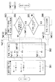
図2は、プリンタ1の制御系を示すブロック図、図3(a)は、一般的な印字ヘッドのノズル配列を示す図、図3(b)は、印字ヘッドのノズル配列の具体例であって64行×2列のノズル配列を示す図である。制御部60は、不良ノズルの特定処理や種々のクリーニング処理を行うためのもので、印字ヘッド12、カートリッジ機構20と電気的に接続されているほか、クリーニング機構40のうちインクポンプ42、クリーニングモータ45と、また、ノズル検出機構51のうちマイクロセンサ52と電気的に接続されている。そして、制御部60は、以下に示すような、ノズル群吐出機能61、ノズル群識別機能62、ノズル特定機能63、ノズル単体クリーニング機能64、ノズルブロッククリーニング機能65が、それぞれ発揮されるように構成されている。
【0024】
ノズル群吐出機能61は、図3(a)に示すように、M行×N列からなるノズルパターンを有する印字ヘッド12について、I行×J列からなるノズルブロックA1〜Anに分割し、各ノズルブロックA内においてi行j列の場所(以下、ノズル番号(i,j)という)に位置する各ノズルから一括してインク液滴を吐出させるように構成されている。各ノズルブロックAのノズル番号(i,j)のノズルの集合を対象ノズル群B(i,j)とする。
【0025】
ノズル群識別機能62は、ノズル検出機構51から出力された対象ノズル群B(i,j)の出力電圧V(i,j)と、全ノズルが正常状態にあるときの対象ノズル群B(i,j)の出力電圧とを比較することによって、対象ノズル群B(i,j)に不良ノズルが含まれているか否かを識別するように構成されている。
【0026】
ノズル特定機能63は、ノズル番号(i,j)を変更しながら、すべての対象ノズル群B(i,j)についてノズル群吐出機能61及びノズル群識別機能62に基づく処理を行う。ある対象ノズル群B(i,j)について実際の出力電圧V(i,j)が異常と判断された場合には、その対象ノズル群B(i,j)に含まれるノズルA1(i,j)〜An(i,j)を、さらに所定数kノズル毎の集合に分割して対象ノズル群Br(i、j)とし、この対象ノズル群Br(i、j)に対してノズル群吐出機能61及びノズル群識別機能62に基づく処理を行う。そして、各対象ノズル群B(i,j)に含まれるノズル数が一になるまで上述の処理を繰り返し行うように構成されている。なお、このようなノズル特定機能63を有効にするか否かは、制御部60に電気的に接続された操作パネル(図示せず)により、使用者が選択できるよう構成されている。
【0027】
ノズル単位クリーニング機能64は、ノズル特定機能63に基づいて特定された不良ノズルのみを対象にしてクリーニング機構40を作動させるように構成されている。また、ノズルブロッククリーニング機能65は、ノズル特定機能63に基づいて特定された不良ノズルを含むノズルブロックAを対象にしてクリーニング機構40を作動させるように構成されている。なお、本実施の形態の場合、制御部60は、ノズル単位クリーニング機能64又はノズルブロッククリーニング機能65のいずれか一つがノズル特定機能63の有効・無効の設定に応じて選択的に実行されるように構成されている。
【0028】
図4は、図3(a)に示す一般的な印字ヘッドについて制御部が行うメイン処理の流れを示すフローチャート、図5は、ノズル特定処理の流れを示すフローチャートである。以下、制御部60の処理及びノズル検出装置50の作用を説明する。ステップ1において、制御部60が、ノズル群吐出機能61に基づき、M行×N列の印字ヘッド12を、n個のI行×J列のノズルパターンとなるようにノズルブロックA1〜Anに分割する。ここで、各ノズルブロックA1〜Anにおける各ノズル13は、行番号1〜i及び列番号1〜jからなるノズル番号(i,j)を用いて対象ノズルA1(i,j)〜An(i,j)として表される。ステップ2では、ノズルブロックAの行数Iと列数Jを繰返し行数及び繰返し列数としてセットするとともに、行数i及び列数jに1を代入し繰返しカウンタとして初期化する。
【0029】
ステップ3では、制御部60が、ノズル群吐出機能61に基づき、行数i及び列数jを共通にした対象ノズルA1(i,j)〜An(i,j)を対象ノズル群B(i,j)とし、この対象ノズル群B(i,j)について印字ヘッド12を駆動して、ノズル検出機構51に対してインク液滴を一括して吐出させる。これにより、マイクロセンサ52は、各対象ノズルA1(i,j)〜An(i,j)から吐出されたインク液滴を同時に受け、各インク液滴との接触状態についてそれぞれ出力電圧に変換したものの総和を実際の総和出力電圧V(i,j)として出力する。
【0030】
ステップ4では、制御部60が、ノズル群識別機能62に基づき、ノズル検出機構51から出力された総和出力電圧V(i,j)と、各対象ノズルA1(i,j)〜An(i,j)にドット抜けが一つも生じていないと仮定した場合における計算上の適正な総和出力電圧とを比較し、総和出力電圧V(i,j)が異常か否か、すなわち、対象ノズル群B(i,j)に不良ノズルが含まれているか否かを識別し、不良ノズルがある場合にはステップ5に分岐し、不良ノズルがない場合にはステップ9に進む。以下、ノズルからインク液滴を吐出させて吐出状態に異常がないか検出する処理(ステップ3〜4)を単に吐出検出ともいう。
【0031】
ステップ5では、不良ノズルの特定が必要とされている場合にはステップ6に進み、不良ノズルの特定が必要とされていない場合にはステップ8に分岐し、クリーニング機構40を作動してすべてのノズル13についてフラッシング、ワイピング、インク吸引等の必要なクリーニング処理を行ってからメイン処理を抜ける。
【0032】
ステップ6のノズル特定処理においては、図5に示すように、ステップ61において、対象ノズル群B(i,j)に含まれる対象ノズルA1(i,j)〜An(i,j)を、k個(<n)のノズルを含むような集合A1(i,j)〜Ak(i,j)、Ak+1(i,j)〜A2k(i,j)、…、An-k+1(i,j)〜An(i,j)に分割し、これらを、ステップ62において、対象ノズル群化する。ここで、A1(i,j)〜Ak(i,j)は、処理手順fw1(1)に従って対象ノズルB1に代入され、Ak+1(i,j)〜A2k(i,j)は、処理手順fw1(2)に従って対象ノズルB2に代入され、以下同様にして、An-k+1(i,j)〜An(i,j)は、処理手順fw1(r)に従って対象ノズルBr(r=n/k)に代入される。
【0033】
ステップ63、64では、上記ステップ3、4と同様、対象ノズル群B1〜Brについて対象ノズルAからインク液滴を一括して吐出させ、総和出力電圧V(i,j)が異常か否かを判断する。すなわち、処理手順fw2(1)に従って対象ノズル群B1を対象として総和出力電圧V(i,j)の異常を判断し、異常がなければ、処理手順bw1(2)、fw2(2)に従って対象ノズル群B2を対象として総和出力電圧(i,j)の異常を判断する。総和出力電圧(i,j)が異常と判断されるまでステップ62〜64の処理が繰り返され、最終的には、処理手順bw1(r)、fw2(r)に従って対象ノズル群Brを対象として、総和出力電圧V(i,j)の異常が判断される。
【0034】
このような対象ノズル群B1〜Brごとの吐出検出を繰り返す間、総和出力電圧V(i,j)に異常があれば(ステップ64)、対象ノズル群Bに含まれる対象ノズルが一つであるか否かを判断し(ステップ65)、対象ノズルが二つ以上であれば、ステップ61、62に戻り処理手順bw2(1)〜bw2(r)に従ってその対象ノズルBをさらに分割して対象ノズル群化し、この対象ノズル群Bに含まれる対象ノズルが一つになるまでステップ61〜64の処理が繰り返される。
【0035】
ステップ65において、対象ノズル群Bに含まれる対象ノズルが一つである場合には、その対象ノズル群Bの属性(当初の対象ノズル群から分割された回数、対象ノズル群の順番等)から対象ノズルが含まれるノズルブロックAを割り出し、対象ノズルを不良ノズルとして特定する。そして、現に行っている対象ノズル群Bが最終的な対象ノズル群Brであれば、メイン処理に戻り、それ以外の場合は、処理手順bw3(2)…bw3(r)に従いステップ62に戻って次の対象ノズル群について不良ノズルを特定する。
【0036】
その後、メイン処理のステップ7において、制御部60が、ノズル単位クリーニング機能64に基づき、クリーニング機構40を作動して特定された不良ノズルのみについてクリーニングを行う。なお、ステップ8において、ノズルブロッククリーニング機能65に基づく場合には、不良ノズルを含むノズルブロックAのすべてのノズル13についてクリーニングが行われる。
【0037】
その後、ステップ9に進んで、行数iを一つ繰り上げ、ステップ10において、その行数iと繰返し行数Iとを比較し、行数iが繰返し行数Iより小さい又は等しい場合には、ステップ3〜ステップ9の処理を繰返し行い、行数iが繰返し行数Iより大きい場合、すなわち、ある固定された列数に対してすべての行数1〜iについての処理が終了した場合には、ステップ11に進む。ステップ11では、列数jを一つ繰り上げ、ステップ12において、その列数jと繰返し行数Jとを比較し、列数jが繰返し列数Jより小さい又は等しい場合には、ステップ3〜ステップ11の処理を繰返し行い、列数jが繰返し行数Jより大きい場合、すなわち、すべての列数1〜jについての処理が終了した場合には、メイン処理を終了する。
【0038】
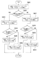
図6は、図3(b)に示す64行×2列のノズル配列を有する印字ヘッドについてのノズル特定処理の流れを示すフローチャートである。メイン処理については、図4を参照し、主に異なる点について説明する。ステップ1において、64行×2列のノズルを、32行(行数i)×1列(列数j)のノズルブロックA1〜A4に分割する。ステップ2では、行数32を繰返し行数Iに代入するとともに、行数iに1を代入し繰返しカウンタとして初期化する。ここで、列数j(=1)については繰返しを考慮する必要がないため、以下列数jに関する記載を省略する。
【0039】
まず、A1(1)〜A4(1)を対象ノズル群B(1)として吐出検出を行う(ステップ3、4)。検出の結果、異常があって不良ノズルを特定する場合には、ステップ5を経てステップ6のノズル特定処理に進む。図6に示すノズル特定処理において、対象ノズル群B(1)に含まれる対象ノズルA1(1)〜A4(1)を、2個含むような集合、例えば、A1(1)、A2(1)と、A3(1)、A4(1)とに分割し、それぞれ対象ノズル群B1(1)、B2(1)とする。そして、対象ノズル群B1(1)の吐出検出を行い(ステップ601、602)、異常である場合には、ステップ603に進んで対象ノズルA1(1)のみの吐出検出を行う。対象ノズルA1(1)についての出力電圧V(1)が異常である場合には(ステップ604)、対象ノズルA1(1)を不良ノズルと特定し(ステップ605)、異常でない場合には、対象ノズルA2(1)を不良ノズルと特定し(ステップ606)、メイン処理に戻る。ここでは、二つの対象ノズルのうちいずれか一方の吐出検出を行い、これに異常がなければ、他方に異常があるとみなして不良ノズルとすることによって、処理を簡略化している。
【0040】
一方、ステップ602において、対象ノズル群B1(1)の総和出力電圧V(1)が異常でない場合には、対象ノズル群B2(1)について吐出検出を行う(ステップ607)。以下、ステップ604〜606と同様に、対象ノズルA3(1)についての出力電圧V(1)が異常か否かを判断し(ステップ608)、異常である場合には対象ノズルA3(1)を不良ノズルとし(ステップ609)、異常でない場合には対象ノズルA4(1)を不良ノズルと特定して(ステップ610)、メイン処理に戻る。メイン処理のステップ7では、特定された不良ノズルのみについてフラッシングを行い、ノズルを正常な状態に回復させる。
【0041】
以下、ステップ9、10により行数iを繰り上げ大小比較することによって、対象ノズルA1(2)〜A4(2)[=対象ノズル群B(2)]…対象ノズルA1(32)〜A4(32)[=対象ノズル群B(32)]についてステップ3〜7の処理を繰り返し行う。
【0042】
以上述べたように本実施の形態によれば、印字ヘッド12のノズルパターンを所定数のノズルが含まれるノズル群に分割し、ノズル群ごとに吐出検出を行うようにしたので、検出に要する処理時間を大幅に削減することができる。例えば、一回のノズルの吐出検出に100msecを要する場合、上記の64行×2列の印字ヘッドにおいて各ノズル毎に吐出検出を行うと、全ノズルを検出するには、12.8sec(=100[msec]×128[ノズル])を要するのに対し、本実施の形態によれば、3.2[sec](=100[msec]×32[ノズル群])に短縮でき、ドット抜けの有無を短時間で検出できる。
【0043】
また、本実施の形態によれば、特定した不良ノズルのみクリーニングを行うことにより、クリーニングで消費されるインク量を削減することができる。
【0044】
一方、ノズルブロックごとにキャッピング可能な構成においては、不良ノズルを含むノズルブロックに対してのみクリーニングを行うことができるので、不良ノズルの特定に時間をかけることなく、クリーニングで消費されるインク量を削減することができる。また、不良ノズルの近傍にあるノズルのうちノズル検出機構によって検出されないノズルも不完全ながら目詰まりしていることもあり得るため、このようなドット抜け予備軍としてのノズルも含めて一括してクリーニングしておくことができる。
【0045】
さらに、本実施の形態によれば、不良ノズルの特定にあたって、対象ノズル群に含まれる対象ノズルを二つにまで絞り込み、二つの対象ノズルのうち一方が異常でない場合に、他方を不良ノズルであるとみなすようにしたので、処理を簡略化し検出時間を短縮することができる。その一方で、異常とされる対象ノズル群に含まれる対象ノズルを一つにまで絞り込むことによって不良ノズルを特定することも可能であり、この場合には、対象ノズル群にドット抜けが生じたノズルが複数含まれていても、それぞれ、不良ノズルであると特定することができる。
【0046】
なお、本発明は上述の実施の形態に限られることなく、種々の変更を行うことができる。例えば、罫線のように列ドット二つで形成するような印字画像について特に印字品質が重要とされない場合には、二つの列ドットのうち一つにドット抜けが生じていても印字画像としては成立するため、このようなドットに対してクリーニングを省略したり、あるいは、二つの列ドットのうち一つが正常であると判断した場合に他のドットについてノズル検出を省略することができる。また、1ドット列間隔でノズルブロックAを設定することができる。
【0047】
また、上記実施の形態においては、ノズル検出機構51として、マイクロセンサを用いて各ノズルから吐出されたインク液滴との接触状態を電圧に変換して出力する例を示したが、温度センサにインク液滴を吐出してこれが蒸発する際に生じる気化熱を電圧に変換して出力するような構成にすることも可能である(特開昭58−217365号公報参照)。
【0048】
【発明の効果】
以上述べたように本発明によれば、ノズル群に不良ノズルが含まれるか否かを判断することにより、ノズル群に不良ノズルが含まれていないと判断した場合には、ノズル群に含まれる個々のノズルについてノズル検出を行う必要がないため、吐出検出に要する時間を大幅に削減することができる。そして、印字保証するために行われる印字処理直前のドット抜け検出及びクリーニングに要する時間が削減されるので、使用者の待ち時間を短縮することができる。
【0049】
また、異常とされる対象ノズル群に含まれる不良ノズルを特定し、特定された不良ノズルについてのみクリーニングを行うことにより、あるいは、異常とされる対象ノズル群に含まれる不良ノズルを含むノズルブロックについてのみクリーニングを行うことにより、クリーニングに要するインク消費量を削減することができる。
【0050】
このように、ドット抜け検出とクリーニングをドット単位ではなく複数のドット単位で行うことにより、全体の処理時間を削減することができる。
【図面の簡単な説明】
【図1】 本実施の形態のプリンタの概略構成を示す図である。
【図2】 本実施の形態の制御部を含む制御系を示すブロック図である。
【図3】(a):一般的な印字ヘッドのノズルブロック化を示す図である。
(b):64行×2列のノズル配列を備えた印字ヘッドのノズルブロック化を示す図である。
【図4】 本実施の形態の制御部が一般的な印字ヘッドについて行うメイン処理の流れを示すフローチャートである。
【図5】 同制御部の同メイン処理においてノズル特定処理の流れを示すフローチャートである。
【図6】 本実施の形態の制御部が64行×2列のノズル配列を備えた印字ヘッドについて行うメイン処理においてノズル特定処理の流れを示すフローチャートである。
【符号の説明】
30 クリーニング装置
40 クリーニング機構
50 ノズル検出装置
51 ノズル検出機構
60 制御部
61 ノズル群吐出機能
62 ノズル群識別機能
63 ノズル特定機能
64 ノズル単体クリーニング機能
65 ノズルブロッククリーニング機能[0001]
BACKGROUND OF THE INVENTION
The present invention relates to an ink jet printer including a cleaning device that detects and cleans clogging (dot missing) of ink nozzles.
[0002]
[Prior art]
An ink jet printer forms a desired print on a print medium by ejecting ink droplets from ink nozzles of a print head. If no ink droplets are ejected from the ink nozzle for a certain period of time, the ink solvent will evaporate and the ink viscosity near the ink nozzle will increase, causing the ink nozzle to become clogged. When a droplet is not ejected or is ejected, it is not an ink droplet of the original size and speed, and a printing defect may occur (hereinafter referred to as dot missing). Further, depending on the use state of the print head, for example, when the reciprocating movement of the print head is repeatedly performed, the ink meniscus of each ink nozzle may be broken, and as a result, missing dots may occur.
[0003]
For this reason, in particular, in printers used in financial relations such as passbook entry and lottery issuance, it is necessary to detect dot omission (clogging of ink nozzles) in advance and guarantee the printing. .
[0004]
[Problems to be solved by the invention]
As described above, in order to guarantee printing, it is necessary to detect missing dots immediately before the printing process. Conventionally, since this missing dot detection is performed for each nozzle, there is a problem that it takes a lot of time and makes the user wait. In addition, when dot missing has occurred even with one nozzle, there has been a problem that ink is wasted because recovery processing (cleaning) has been performed for all nozzles.
[0005]
The present invention has been made to solve such technical problems, and the object of the present invention is to efficiently detect missing dots before printing processing and to determine whether or not cleaning is necessary in a short time. It is an object of the present invention to provide an ink jet printer capable of performing the above. It is another object of the present invention to provide an ink jet printer that can reduce the amount of ink required for cleaning by specifying a nozzle in which dot missing has occurred.
[0006]
[Means for Solving the Problems]
In order to achieve the above object, the present invention relates to each nozzle of a print head in which a plurality of nozzles capable of ejecting ink droplets are arranged. The ink droplets ejected from the nozzles are simultaneously received by a microsensor, and the total output voltage of the contact state between each ink droplet and the microsensor is converted into an output voltage, thereby eliminating dot missing. Detect presence or absence A plurality of nozzles of the print head divided into a plurality of nozzle groups each including a predetermined number of nozzles, and ink droplets are collectively collected from the nozzles included in the nozzle groups. Whether or not a defective nozzle is included in the nozzle group based on a nozzle group discharge function to be discharged and a total output value of the predetermined output values from each nozzle for the nozzle group emitted from the nozzle detection mechanism A nozzle group identification function for identifying the nozzle group, and when the nozzle group is identified as including a defective nozzle, the nozzle group is further divided and defective by repeatedly operating the nozzle group ejection function and the nozzle group identification function A control unit having a nozzle specifying function for specifying a nozzle, and a cleaning mechanism for cleaning each nozzle of the print head. The control unit is configured such that the nozzle group ejection function divides a plurality of nozzles of the print head into nozzle blocks having a nozzle array having a predetermined number of rows and columns, and each nozzle having the same relative position in the nozzle block. The nozzle group included in the block is configured as the nozzle group, and when the nozzle group is identified as containing a defective nozzle based on the nozzle group identification function, A nozzle block cleaning function for operating the cleaning mechanism for the nozzle block including a defective nozzle, and a single nozzle cleaning function for operating the cleaning mechanism only for the defective nozzle specified based on the nozzle specifying function; And selectively operating these two cleaning functions A cleaning apparatus characterized.
[0007]
According to the present invention, a plurality of nozzles of a print head are divided into nozzle blocks having a nozzle array having a predetermined number of rows and columns, and a set of nozzles included in each nozzle block having the same relative position in the nozzle block. Are used as nozzle groups, and nozzles are discharged from each nozzle group to detect nozzles. If the nozzle group does not contain defective nozzles, further nozzle detection is performed for individual nozzles included in the nozzle group. Because it is not necessary, the time required for nozzle detection can be greatly reduced to shorten the dot missing detection processing time, and it is possible to improve the efficiency of the entire printer without waiting for the user. In addition, a cleaning mechanism for cleaning each nozzle of the print head is provided, and its control unit is designed to perform nozzle based on the nozzle group identification function. When it is identified that a defective nozzle is included in the group, only the defective nozzle specified based on the nozzle block cleaning function that activates the cleaning mechanism for the nozzle block including the defective nozzle and the nozzle specifying function is targeted In addition, the nozzle cleaning function for operating the cleaning mechanism is selectively operated, and by selectively operating these two cleaning functions, the nozzles that are not detected by the nozzle detection mechanism among the nozzles in the vicinity of the defective nozzle are also excluded. Since it may be clogged completely, it can be cleaned in a lump, including the nozzle as a dot missing reserve army, and in some cases, only for the specified defective nozzle It is sufficient to perform cleaning. It is possible to reduce the consumption.
[0008]
[0009]
In the present invention, the control unit is configured to repeat a series of processes based on the nozzle group discharge function and the nozzle group identification function until the target nozzles included in the target nozzle group become one. Is also effective. According to this invention, a defective nozzle can be specified by narrowing down to one target nozzle included in the target nozzle group regarded as abnormal.
[0010]
Furthermore, in the present invention, the control unit may determine whether the nozzle group identification function includes a defective nozzle in the nozzle group by comparing an actual total output value of the nozzle group with a theoretical output value. It is also effective to be configured to identify whether or not.
[0011]
[0012]
[0013]
The ink jet printer of the present invention includes a print head having a nozzle forming surface on which a plurality of ink nozzles are formed, and a cleaning mechanism for cleaning each ink nozzle of the print head, and the ink liquid is supplied from the ink nozzle. In an ink jet printer that performs printing by discharging droplets, the plurality of ink nozzles are divided into ink nozzle blocks of an ink nozzle array having a predetermined number of rows and columns, and the relative positions in the ink nozzle blocks are the same. An ejection control means for ejecting ink droplets for each set of ink nozzles included in the ink nozzle block as an ink nozzle group; and
Ink droplets from the ink nozzles Simultaneously received by a microsensor, the contact state between each ink droplet and the microsensor is converted to an output voltage, and the total output voltage is output to detect the presence or absence of missing dots A discharge detection means configured to:
Nozzle group identification means for identifying whether or not the ink nozzle group includes a defective ink nozzle based on the total output value emitted from the ejection detection means; and the ink nozzle group includes a defective ink nozzle. The ink nozzle group is further divided, and the discharge control means and the nozzle group identification means are repeatedly operated to identify defective ink nozzles, and the ink based on the nozzle group identification means A nozzle block cleaning unit that activates the cleaning mechanism for the ink nozzle block including the defective ink nozzle when it is identified that the nozzle group includes a defective ink nozzle; Nozzle that activates the cleaning mechanism only for defective ink nozzles A single cleaning unit, an ink jet printer characterized by having a cleaning function selecting means for selectively actuating said two cleaning function.
[0014]
[0015]
[0016]
In addition, it is appropriate to grasp the present invention as a method for controlling an ink jet printer, and even in that case, the same operation and effect can be obtained.
[0017]
DETAILED DESCRIPTION OF THE INVENTION
Hereinafter, preferred embodiments of a cleaning device and a printer having the same according to the present invention will be described in detail with reference to the drawings. FIG. 1 is a diagram illustrating a schematic configuration of a printer according to the present embodiment. As shown in FIG. 1, the
[0018]
The
[0019]
The
[0020]
The
[0021]
The
[0022]
The
[0023]
2 is a block diagram showing a control system of the
[0024]
As shown in FIG. 3A, the nozzle
[0025]
The nozzle
[0026]
The
[0027]
The nozzle
[0028]
FIG. 4 is a flowchart showing the flow of main processing performed by the control unit for the general print head shown in FIG. 3A, and FIG. 5 is a flowchart showing the flow of nozzle specifying processing. Hereinafter, the process of the control unit 60 and the operation of the
[0029]
In step 3, the control unit 60 assigns the target nozzles A <b> 1 (i, j) to An (i, j) having the common number of rows i and columns j based on the nozzle
[0030]
In
[0031]
In
[0032]
In the nozzle specifying process in
[0033]
In
[0034]
If there is an abnormality in the total output voltage V (i, j) while repeating the ejection detection for each of the target nozzle groups B1 to Br (step 64), there is one target nozzle included in the target nozzle group B. If there are two or more target nozzles, the process returns to
[0035]
If there is only one target nozzle included in the target nozzle group B in
[0036]
Thereafter, in
[0037]
Thereafter, the process proceeds to step 9 where the number of lines i is incremented by one. In
[0038]
FIG. 6 is a flowchart showing the flow of nozzle identification processing for a print head having the 64 × 2 nozzle array shown in FIG. The main process will be described mainly with reference to FIG. In
[0039]
First, discharge detection is performed using A1 (1) to A4 (1) as the target nozzle group B (1) (steps 3 and 4). As a result of detection, when there is an abnormality and a defective nozzle is specified, the process proceeds to step 6 through
[0040]
On the other hand, if the total output voltage V (1) of the target nozzle group B1 (1) is not abnormal in step 602, discharge detection is performed for the target nozzle group B2 (1) (step 607). Thereafter, similarly to
[0041]
Thereafter, the target nozzles A1 (2) to A4 (2) [= target nozzle group B (2)]... ) Repeat steps 3 to 7 for [= target nozzle group B (32)].
[0042]
As described above, according to the present embodiment, the nozzle pattern of the
[0043]
Further, according to the present embodiment, it is possible to reduce the amount of ink consumed by cleaning by cleaning only the specified defective nozzle.
[0044]
On the other hand, in the configuration in which capping can be performed for each nozzle block, cleaning can be performed only for the nozzle block including the defective nozzle. Therefore, the amount of ink consumed in the cleaning can be reduced without taking time to identify the defective nozzle. Can be reduced. In addition, the nozzles that are not detected by the nozzle detection mechanism among the nozzles in the vicinity of the defective nozzle may be clogged although they are incomplete. Can be kept.
[0045]
Furthermore, according to the present embodiment, when specifying defective nozzles, the target nozzles included in the target nozzle group are narrowed down to two, and when one of the two target nozzles is not abnormal, the other is a defective nozzle. Therefore, the processing can be simplified and the detection time can be shortened. On the other hand, it is also possible to identify defective nozzles by narrowing down the target nozzles included in the target nozzle group to be abnormal to one, and in this case, nozzles with missing dots in the target nozzle group Even if a plurality of are included, each can be identified as a defective nozzle.
[0046]
The present invention is not limited to the above-described embodiment, and various changes can be made. For example, if the print quality is not particularly important for a print image that is formed with two row dots such as a ruled line, even if a dot omission occurs in one of the two row dots, the print image is established. Therefore, cleaning of such dots can be omitted, or nozzle detection can be omitted for other dots when it is determined that one of the two row dots is normal. Further, the nozzle block A can be set at intervals of one dot row.
[0047]
In the above embodiment, as the
[0048]
【The invention's effect】
As described above, according to the present invention, when it is determined that the nozzle group does not include a defective nozzle by determining whether the nozzle group includes a defective nozzle, the nozzle group includes the defective nozzle. Since it is not necessary to perform nozzle detection for each nozzle, the time required for ejection detection can be greatly reduced. Since the time required for dot missing detection and cleaning immediately before the printing process performed to guarantee printing is reduced, the waiting time of the user can be shortened.
[0049]
In addition, by identifying defective nozzles included in the target nozzle group to be abnormal and cleaning only the specified defective nozzles, or nozzle blocks including defective nozzles included in the target nozzle group to be abnormal By performing only cleaning, it is possible to reduce the ink consumption required for cleaning.
[0050]
In this way, by performing dot missing detection and cleaning not in units of dots but in units of a plurality of dots, the overall processing time can be reduced.
[Brief description of the drawings]
FIG. 1 is a diagram illustrating a schematic configuration of a printer according to an embodiment.
FIG. 2 is a block diagram showing a control system including a control unit of the present embodiment.
FIG. 3A is a diagram showing nozzle block formation of a general print head.
(B): It is a figure which shows nozzle block formation of the print head provided with the nozzle arrangement of 64 rows x 2 columns.
FIG. 4 is a flowchart showing a flow of main processing performed by a control unit of the present embodiment for a general print head.
FIG. 5 is a flowchart showing a flow of nozzle specifying processing in the main processing of the control unit.
FIG. 6 is a flowchart showing a flow of nozzle specifying processing in the main processing performed by the control unit of the present embodiment for a print head having a nozzle array of 64 rows × 2 columns.
[Explanation of symbols]
30 Cleaning device
40 Cleaning mechanism
50 nozzle detector
51 Nozzle detection mechanism
60 Control unit
61 Nozzle group discharge function
62 Nozzle group identification function
63 Nozzle specific function
64 single nozzle cleaning function
65 Nozzle block cleaning function
Claims (5)
前記印字ヘッドの複数のノズルを、それぞれ所定数のノズルを含む複数のノズル群に分割し、当該ノズル群に含まれる前記ノズルから一括してインク液滴を吐出させるノズル群吐出機能と、前記ノズル検出機構から発せられた前記ノズル群についての各ノズルからの前記所定の出力値の総和出力値に基づいて前記ノズル群に不良ノズルが含まれているか否かを識別するノズル群識別機能と、前記ノズル群に不良ノズルが含まれていると識別された場合に当該ノズル群をさらに分割し前記ノズル群吐出機能及びノズル群識別機能を繰り返し作動させることによって不良ノズルを特定するノズル特定機能とを有する制御部と、
前記印字ヘッドの各ノズルをクリーニングするためのクリーニング機構とを備え、
前記制御部は、前記ノズル群吐出機能が、前記印字ヘッドの複数のノズルを所定の行数及び列数からなるノズル配列のノズルブロックに分割し、当該ノズルブロック内における相対位置が同一の各ノズルブロックに含まれる前記ノズルの集合を前記ノズル群とするように構成されているとともに、さらに、前記ノズル群識別機能に基づいて前記ノズル群に不良ノズルが含まれていると識別された場合に前記不良ノズルを含む前記ノズルブロックを対象にして前記クリーニング機構を作動させるノズルブロッククリーニング機能と前記ノズル特定機能に基づいて特定された不良ノズルのみを対象にして前記クリーニング機構を作動させるノズル単体クリーニング機能とを有し、且つ、これら2つのクリーニング機能を選択的に作動させることを特徴とするクリーニング装置。For each nozzle of a print head in which a plurality of nozzles capable of ejecting ink droplets are arranged, the ink droplets ejected from the nozzles are simultaneously received by a microsensor, and each of the ink droplets and the microsensor A nozzle detection mechanism configured to detect the presence or absence of missing dots by outputting a total output voltage of the contact state converted into an output voltage ;
A nozzle group discharge function for dividing the plurality of nozzles of the print head into a plurality of nozzle groups each including a predetermined number of nozzles, and discharging ink droplets collectively from the nozzles included in the nozzle group; and the nozzles A nozzle group identification function for identifying whether or not a defective nozzle is included in the nozzle group based on a total output value of the predetermined output values from each nozzle for the nozzle group emitted from a detection mechanism; When it is identified that a defective nozzle is included in the nozzle group, the nozzle group is further divided and a nozzle specifying function for specifying a defective nozzle by repeatedly operating the nozzle group discharge function and the nozzle group identification function is provided. A control unit;
A cleaning mechanism for cleaning each nozzle of the print head,
The control unit is configured such that the nozzle group ejection function divides a plurality of nozzles of the print head into nozzle blocks having a nozzle array having a predetermined number of rows and columns, and each nozzle having the same relative position in the nozzle block. The nozzle group included in the block is configured as the nozzle group, and when the nozzle group is identified as containing a defective nozzle based on the nozzle group identification function, A nozzle block cleaning function for operating the cleaning mechanism for the nozzle block including the defective nozzle, and a single nozzle cleaning function for operating the cleaning mechanism only for the defective nozzle specified based on the nozzle specifying function; And selectively operating these two cleaning functions. Cleaning apparatus according to symptoms.
前記複数のインクノズルを所定の行数及び列数からなるインクノズル配列のインクノズルブロックに分割し、当該インクノズルブロック内における相対位置が同一の各インクノズルブロックに含まれるインクノズルの集合をインクノズル群として、当該集合ごとにインク液滴を吐出させる吐出制御手段と、
前記インクノズルからのインク液滴をマイクロセンサで同時に受け、それぞれの前記インク液滴と前記マイクロセンサとの接触状態を出力電圧に変換したものの総和出力電圧を出力して、ドット抜けの有無を検出するよう構成された吐出検出手段と、
前記吐出検出手段から発せられた前記総和出力値により、前記インクノズル群に不良インクノズルが含まれているか否かを識別するノズル群識別手段と、
前記インクノズル群に不良インクノズルが含まれていると識別された場合に当該インクノズル群をさらに分割し前記吐出制御手段及びノズル群識別手段を繰り返し動作させて不良インクノズルを特定するノズル特定手段と、
前記ノズル群識別手段に基づいて前記インクノズル群に不良インクノズルが含まれていると識別された場合に前記不良インクノズルを含む前記インクノズルブロックを対象にして前記クリーニング機構を作動させるノズルブロッククリーニング手段と、
前記ノズル特定手段により特定された不良インクノズルのみを対象にして前記クリーニング機構を作動させるノズル単体クリーニング手段と、
前記2つのクリーニング機能を選択的に作動させるクリーニング機能選択手段とを有することを特徴とするインクジェットプリンタ。An ink jet having a print head having a nozzle forming surface on which a plurality of ink nozzles are formed and a cleaning mechanism for cleaning each ink nozzle of the print head, and performing printing by discharging ink droplets from the ink nozzles In the printer
The plurality of ink nozzles are divided into ink nozzle blocks having an ink nozzle arrangement having a predetermined number of rows and columns, and a set of ink nozzles included in each ink nozzle block having the same relative position in the ink nozzle block is used as an ink. As a nozzle group, ejection control means for ejecting ink droplets for each set, and
Ink droplets from the ink nozzles are simultaneously received by a micro sensor, and the contact state between each of the ink droplets and the micro sensor is converted into an output voltage. A discharge detection means configured to:
Nozzle group identifying means for identifying whether or not a defective ink nozzle is included in the ink nozzle group, based on the total output value emitted from the ejection detection means;
Nozzle specifying means for specifying a defective ink nozzle by further dividing the ink nozzle group when the ink nozzle group is identified as containing a defective ink nozzle and repeatedly operating the discharge control means and nozzle group identification means When,
Nozzle block cleaning that activates the cleaning mechanism for the ink nozzle block including the defective ink nozzle when it is determined that the ink nozzle group includes a defective ink nozzle based on the nozzle group identifying means. Means,
A single nozzle cleaning means for operating the cleaning mechanism only for defective ink nozzles specified by the nozzle specifying means;
An ink jet printer comprising: a cleaning function selecting unit that selectively activates the two cleaning functions.
前記複数のインクノズルを所定の行数及び列数からなるインクノズル配列のインクノズルブロックに分割し、当該インクノズルブロック内における相対位置が同一の各インクノズルブロックに含まれるインクノズルの集合をインクノズル群として、当該集合ごとにインク液滴を吐出させる吐出制御ステップと、
前記インクノズルからのインク液滴をマイクロセンサで同時に受け、それぞれの前記インク液滴と前記マイクロセンサとの接触状態を出力電圧に変換したものの総和出力電圧を出力して、ドット抜けの有無を検出するよう構成された吐出検出ステップと、
前記分割されたインクノズルの集合ごとに吐出検出を行なわせ、当該集合に含まれる前記インクノズルが不良であるか否かを判断するノズル群識別ステップと、
前記インクノズル群に不良インクノズルが含まれている場合に該不良インクノズルを特定することが必要であるか否かを判断する特定化判断ステップと、
前記不良インクノズルを特定することが必要でないと判断された場合に、前記ノズル群識別ステップにより前記インクノズル群に不良インクノズルが含まれていると識別された当該不良インクノズルを含む前記インクノズルブロックを対象にして前記クリーニング機構を作動させるノズルブロッククリーニングステップと、
前記不良インクノズルを特定することが必要であると判断された場合に、前記インクノズル群をさらに分割し前記吐出制御ステップ及びノズル群識別ステップを繰り返し実行して不良インクノズルを特定し、該特定された不良インクノズルのみを対象にして前記クリーニング機構を作動させるインクノズル特定・ノズル単体クリーニングステップとを有することを特徴とするインクジェットプリンタの制御方法。An ink jet printer having a print head having a nozzle forming surface on which a plurality of ink nozzles are formed and a cleaning mechanism for cleaning each nozzle of the print head, and performing printing by discharging ink droplets from the ink nozzles In a method of controlling
The plurality of ink nozzles are divided into ink nozzle blocks having an ink nozzle arrangement having a predetermined number of rows and columns, and a set of ink nozzles included in each ink nozzle block having the same relative position in the ink nozzle block is used as an ink. As a nozzle group, an ejection control step for ejecting ink droplets for each set, and
Ink droplets from the ink nozzles are simultaneously received by a micro sensor, and the contact state between each of the ink droplets and the micro sensor is converted into an output voltage. A discharge detection step configured to:
A nozzle group identification step for performing ejection detection for each of the divided ink nozzle groups and determining whether or not the ink nozzles included in the group are defective;
A determination step of determining whether or not it is necessary to specify the defective ink nozzle when the ink nozzle group includes the defective ink nozzle;
When it is determined that it is not necessary to specify the defective ink nozzle, the ink nozzle including the defective ink nozzle identified by the nozzle group identification step as being defective in the ink nozzle group A nozzle block cleaning step of operating the cleaning mechanism for a block;
When it is determined that it is necessary to identify the defective ink nozzle, the ink nozzle group is further divided, and the ejection control step and the nozzle group identification step are repeatedly performed to identify the defective ink nozzle, and the identification is performed. An ink jet printer control method comprising: an ink nozzle identification / nozzle single unit cleaning step for operating the cleaning mechanism only for the defective ink nozzles.
Priority Applications (1)
| Application Number | Priority Date | Filing Date | Title |
|---|---|---|---|
| JP2001315858A JP4066131B2 (en) | 2001-10-12 | 2001-10-12 | Cleaning device, inkjet printer, and control method thereof |
Applications Claiming Priority (1)
| Application Number | Priority Date | Filing Date | Title |
|---|---|---|---|
| JP2001315858A JP4066131B2 (en) | 2001-10-12 | 2001-10-12 | Cleaning device, inkjet printer, and control method thereof |
Related Child Applications (1)
| Application Number | Title | Priority Date | Filing Date |
|---|---|---|---|
| JP2007177184A Division JP4479757B2 (en) | 2007-07-05 | 2007-07-05 | Print head cleaning device and cleaning method |
Publications (3)
| Publication Number | Publication Date |
|---|---|
| JP2003118133A JP2003118133A (en) | 2003-04-23 |
| JP2003118133A5 JP2003118133A5 (en) | 2005-06-09 |
| JP4066131B2 true JP4066131B2 (en) | 2008-03-26 |
Family
ID=19133969
Family Applications (1)
| Application Number | Title | Priority Date | Filing Date |
|---|---|---|---|
| JP2001315858A Expired - Fee Related JP4066131B2 (en) | 2001-10-12 | 2001-10-12 | Cleaning device, inkjet printer, and control method thereof |
Country Status (1)
| Country | Link |
|---|---|
| JP (1) | JP4066131B2 (en) |
Families Citing this family (16)
| Publication number | Priority date | Publication date | Assignee | Title |
|---|---|---|---|---|
| JP4238734B2 (en) | 2004-01-21 | 2009-03-18 | セイコーエプソン株式会社 | Droplet ejection head driving method, droplet ejection apparatus, and device manufacturing method |
| US7490918B2 (en) | 2004-03-05 | 2009-02-17 | Fujifilm Corporation | Droplet determination device and droplet determination method for droplet discharge apparatus |
| JP2009012392A (en) | 2007-07-06 | 2009-01-22 | Seiko Epson Corp | Device and method for discharging liquid |
| JP5176570B2 (en) | 2008-02-01 | 2013-04-03 | セイコーエプソン株式会社 | Recording apparatus and control method |
| JP5228975B2 (en) | 2008-03-26 | 2013-07-03 | セイコーエプソン株式会社 | Printing invalid indication printing method, inkjet printer, printer driver, and printing invalidity notification method |
| JP5239491B2 (en) | 2008-05-08 | 2013-07-17 | セイコーエプソン株式会社 | Nozzle discharge state inspection method, discharge state inspection mechanism, and droplet discharge device |
| US20120229537A1 (en) * | 2011-03-08 | 2012-09-13 | Larry Ernst | Defective Jet Detection Mechanism |
| JP4962642B2 (en) * | 2011-09-16 | 2012-06-27 | セイコーエプソン株式会社 | Nozzle inspection device, nozzle inspection method, and inspection program |
| JP2013146981A (en) * | 2012-01-23 | 2013-08-01 | Seiko Epson Corp | Inspection device of droplet ejection apparatus |
| JP6156524B2 (en) * | 2016-01-19 | 2017-07-05 | セイコーエプソン株式会社 | Droplet discharge device |
| US9785873B2 (en) | 2016-02-16 | 2017-10-10 | Ricoh Company, Ltd. | Halftone calibration mechanism |
| JP6472058B2 (en) * | 2016-03-29 | 2019-02-20 | 富士フイルム株式会社 | Image forming apparatus and image correction method |
| JP2017047692A (en) * | 2016-12-14 | 2017-03-09 | セイコーエプソン株式会社 | Droplet discharge device |
| US11184504B2 (en) | 2017-02-16 | 2021-11-23 | Ricoh Company, Ltd. | Dynamic printing system compensation mechanism |
| US10442211B2 (en) | 2017-02-21 | 2019-10-15 | Ricoh Company, Ltd. | Dual pass uniformity printing compensation mechanism |
| JP7266424B2 (en) * | 2019-02-28 | 2023-04-28 | キヤノン株式会社 | DEVICE SUBSTRATE, PRINT HEAD, AND PRINTING DEVICE |
-
2001
- 2001-10-12 JP JP2001315858A patent/JP4066131B2/en not_active Expired - Fee Related
Also Published As
| Publication number | Publication date |
|---|---|
| JP2003118133A (en) | 2003-04-23 |
Similar Documents
| Publication | Publication Date | Title |
|---|---|---|
| JP4066131B2 (en) | Cleaning device, inkjet printer, and control method thereof | |
| JP4479757B2 (en) | Print head cleaning device and cleaning method | |
| EP1059172B1 (en) | An ink jet printing apparatus and a judgement method of an ink jet ejection state of an ink jet head | |
| JP5191422B2 (en) | Ejection surface cleaning device, liquid ejection device, and ejection surface cleaning method | |
| US7540580B2 (en) | Liquid ejection head and ejection abnormality determination method | |
| US7798588B2 (en) | Liquid ejecting apparatus and liquid ejecting method | |
| US20040246294A1 (en) | Method of cleaning print head | |
| JPH08244244A (en) | Nozzle cleaning method of ink jet printer | |
| US7413278B2 (en) | Image forming apparatus and ejection determining method | |
| US7810898B2 (en) | Liquid ejection apparatus and maintenance method for liquid ejection head | |
| JP2007320288A (en) | Control method of undischarge nozzle of ink-jet printer | |
| US6447096B1 (en) | Ink jet recording apparatus and recovery method therefor | |
| JP4185738B2 (en) | Inkjet recording apparatus and inkjet recording method | |
| US7240983B2 (en) | Inkjet recording apparatus and preliminary discharge control method | |
| US6595611B1 (en) | Ink ejection tracking for controlling printhead nozzle maintenance | |
| JP2001277543A (en) | Execution of inspection of ink drop discharge before periodic flushing | |
| JP2012166375A (en) | Inkjet printing apparatus and recovery method for print head thereof | |
| JP2004167852A (en) | Ink-jet printer | |
| JP2003089226A (en) | Cleaning controller, ink jet printer, its controlling method and information recording medium | |
| JP6150537B2 (en) | Ink jet recording apparatus and recording head wiping method | |
| JP2005104037A (en) | Image forming device and recording control method | |
| JP3514235B2 (en) | Ink jet recording apparatus and ink droplet ejection inspection method | |
| JP2008179069A (en) | Liquid discharge device | |
| EP1688258B1 (en) | Method of initialising an inkjet printhead, and an inkjet printer which has been modified for this method to be applied | |
| JP2008143150A (en) | Inkjet recording device and method for detecting ink delivery condition |
Legal Events
| Date | Code | Title | Description |
|---|---|---|---|
| A521 | Written amendment |
Free format text: JAPANESE INTERMEDIATE CODE: A523 Effective date: 20040830 |
|
| A621 | Written request for application examination |
Free format text: JAPANESE INTERMEDIATE CODE: A621 Effective date: 20040830 |
|
| A977 | Report on retrieval |
Free format text: JAPANESE INTERMEDIATE CODE: A971007 Effective date: 20060615 |
|
| A131 | Notification of reasons for refusal |
Effective date: 20060620 Free format text: JAPANESE INTERMEDIATE CODE: A131 |
|
| A521 | Written amendment |
Effective date: 20060808 Free format text: JAPANESE INTERMEDIATE CODE: A523 |
|
| RD03 | Notification of appointment of power of attorney |
Effective date: 20060808 Free format text: JAPANESE INTERMEDIATE CODE: A7423 |
|
| A131 | Notification of reasons for refusal |
Effective date: 20061108 Free format text: JAPANESE INTERMEDIATE CODE: A131 |
|
| A521 | Written amendment |
Free format text: JAPANESE INTERMEDIATE CODE: A523 Effective date: 20061208 |
|
| A131 | Notification of reasons for refusal |
Free format text: JAPANESE INTERMEDIATE CODE: A131 Effective date: 20070516 |
|
| A521 | Written amendment |
Free format text: JAPANESE INTERMEDIATE CODE: A523 Effective date: 20070705 |
|
| TRDD | Decision of grant or rejection written | ||
| A01 | Written decision to grant a patent or to grant a registration (utility model) |
Free format text: JAPANESE INTERMEDIATE CODE: A01 Effective date: 20071212 |
|
| A61 | First payment of annual fees (during grant procedure) |
Free format text: JAPANESE INTERMEDIATE CODE: A61 Effective date: 20071225 |
|
| FPAY | Renewal fee payment (prs date is renewal date of database) |
Year of fee payment: 3 Free format text: PAYMENT UNTIL: 20110118 |
|
| R150 | Certificate of patent (=grant) or registration of utility model |
Free format text: JAPANESE INTERMEDIATE CODE: R150 |
|
| FPAY | Renewal fee payment (prs date is renewal date of database) |
Free format text: PAYMENT UNTIL: 20110118 Year of fee payment: 3 |
|
| FPAY | Renewal fee payment (prs date is renewal date of database) |
Year of fee payment: 4 Free format text: PAYMENT UNTIL: 20120118 |
|
| LAPS | Cancellation because of no payment of annual fees |