JP4065437B2 - Calibration of equipment location systems using radio signal strength - Google Patents
Calibration of equipment location systems using radio signal strength Download PDFInfo
- Publication number
- JP4065437B2 JP4065437B2 JP2004090393A JP2004090393A JP4065437B2 JP 4065437 B2 JP4065437 B2 JP 4065437B2 JP 2004090393 A JP2004090393 A JP 2004090393A JP 2004090393 A JP2004090393 A JP 2004090393A JP 4065437 B2 JP4065437 B2 JP 4065437B2
- Authority
- JP
- Japan
- Prior art keywords
- kernel
- signal
- properties
- signal properties
- regression
- Prior art date
- Legal status (The legal status is an assumption and is not a legal conclusion. Google has not performed a legal analysis and makes no representation as to the accuracy of the status listed.)
- Expired - Fee Related
Links
Images


Classifications
-
- G—PHYSICS
- G01—MEASURING; TESTING
- G01S—RADIO DIRECTION-FINDING; RADIO NAVIGATION; DETERMINING DISTANCE OR VELOCITY BY USE OF RADIO WAVES; LOCATING OR PRESENCE-DETECTING BY USE OF THE REFLECTION OR RERADIATION OF RADIO WAVES; ANALOGOUS ARRANGEMENTS USING OTHER WAVES
- G01S5/00—Position-fixing by co-ordinating two or more direction or position line determinations; Position-fixing by co-ordinating two or more distance determinations
- G01S5/02—Position-fixing by co-ordinating two or more direction or position line determinations; Position-fixing by co-ordinating two or more distance determinations using radio waves
- G01S5/0205—Details
- G01S5/021—Calibration, monitoring or correction
-
- G—PHYSICS
- G01—MEASURING; TESTING
- G01C—MEASURING DISTANCES, LEVELS OR BEARINGS; SURVEYING; NAVIGATION; GYROSCOPIC INSTRUMENTS; PHOTOGRAMMETRY OR VIDEOGRAMMETRY
- G01C21/00—Navigation; Navigational instruments not provided for in groups G01C1/00 - G01C19/00
- G01C21/20—Instruments for performing navigational calculations
- G01C21/206—Instruments for performing navigational calculations specially adapted for indoor navigation
-
- G—PHYSICS
- G01—MEASURING; TESTING
- G01S—RADIO DIRECTION-FINDING; RADIO NAVIGATION; DETERMINING DISTANCE OR VELOCITY BY USE OF RADIO WAVES; LOCATING OR PRESENCE-DETECTING BY USE OF THE REFLECTION OR RERADIATION OF RADIO WAVES; ANALOGOUS ARRANGEMENTS USING OTHER WAVES
- G01S5/00—Position-fixing by co-ordinating two or more direction or position line determinations; Position-fixing by co-ordinating two or more distance determinations
- G01S5/02—Position-fixing by co-ordinating two or more direction or position line determinations; Position-fixing by co-ordinating two or more distance determinations using radio waves
- G01S5/0252—Radio frequency fingerprinting
- G01S5/02528—Simulating radio frequency fingerprints
-
- H—ELECTRICITY
- H04—ELECTRIC COMMUNICATION TECHNIQUE
- H04W—WIRELESS COMMUNICATION NETWORKS
- H04W64/00—Locating users or terminals or network equipment for network management purposes, e.g. mobility management
-
- H—ELECTRICITY
- H04—ELECTRIC COMMUNICATION TECHNIQUE
- H04W—WIRELESS COMMUNICATION NETWORKS
- H04W16/00—Network planning, e.g. coverage or traffic planning tools; Network deployment, e.g. resource partitioning or cells structures
- H04W16/18—Network planning tools
- H04W16/20—Network planning tools for indoor coverage or short range network deployment
-
- H—ELECTRICITY
- H04—ELECTRIC COMMUNICATION TECHNIQUE
- H04W—WIRELESS COMMUNICATION NETWORKS
- H04W16/00—Network planning, e.g. coverage or traffic planning tools; Network deployment, e.g. resource partitioning or cells structures
- H04W16/22—Traffic simulation tools or models
- H04W16/225—Traffic simulation tools or models for indoor or short range network
-
- H—ELECTRICITY
- H04—ELECTRIC COMMUNICATION TECHNIQUE
- H04W—WIRELESS COMMUNICATION NETWORKS
- H04W88/00—Devices specially adapted for wireless communication networks, e.g. terminals, base stations or access point devices
- H04W88/18—Service support devices; Network management devices
Description
本発明は、IEEE802.11装置に関し、より詳細には、無線信号強度を用いる無線装置の位置決めに関する。 The present invention relates to IEEE 802.11 devices and, more particularly, to positioning wireless devices using wireless signal strength.
建物内部のユーザおよび装置の位置を知ることは、ロケーションベースのサービスおよびユビキタスコンピューティングの側面にとって重要な必要条件である。位置判定に対する1つの有望な手法は、無線装置のIEEE802.11無線信号強度の測定による三角測量を介するものである。IEEE802.11ロケーションベースシステムの最も魅力的な特徴の1つは、多くの建物に既に存在する無線ネットワーク以外の追加基盤を必要としないことである。このことは、追加の機器の設置および保守を必要とする、能動的/受動的なバッジおよびカメラを利用する他の人物追跡システムとは対象的である。 Knowing the location of users and devices within a building is an important requirement for aspects of location-based services and ubiquitous computing. One promising approach to position determination is via triangulation by measuring wireless device IEEE 802.11 wireless signal strength. One of the most attractive features of an IEEE 802.11 location-based system is that it requires no additional infrastructure other than a wireless network that already exists in many buildings. This is in contrast to other person tracking systems that utilize active / passive badges and cameras that require the installation and maintenance of additional equipment.
802.11無線クライアントを位置センサとして(たとえば、ポータブルコンピュータを受信機として)使うことは、ロケーションベースのサービスを可能にする方法としてますます一般的になっている。複数のアクセスポイント(AP)からの信号強度の三角測量を用いて、受信装置の位置を数メートルの範囲まで正確に示すことができる。ただし、このレベルの正確さは、信号強度の、空間的に高密度なキャリブレーション(calibration)データを位置に応じて取得するために、単調で時間のかかる手作業を必要とするという代償を払って得られる。 Using an 802.11 wireless client as a position sensor (eg, a portable computer as a receiver) is becoming an increasingly common way to enable location-based services. Using triangulation of signal strength from multiple access points (APs), the location of the receiving device can be accurately shown to a range of a few meters. However, this level of accuracy comes at the cost of requiring monotonous and time-consuming manual work to obtain spatially dense calibration data of signal strength as a function of location. Obtained.
いくつかの異なるAPからのネットワーククライアントに関する無線信号強度の測定結果を知った上で、研究者達は、どのようにして位置を数メートルの範囲まで計算するか示している。このタイプの位置測定は、特に興味を引くものである。というのは、この測定は建物の既存の装置およびそのユーザを利用するからであり、GPS(全地球位置発見システム)およびセル電話の位置信号がしばしば不調となる屋内でも機能するからである。しかし、このようなシステムの正確さは通常、厳密なキャリブレーション手順に依存し、この手順は、建物内部の多数の異なる既知の位置、および異なる方向に無線クライアント受信機を物理的に移動することから成り立つ。このような作業に誰かが資源を費やすことを期待するのは、しばしば現実的でない。新製品の役割としてこのような期待が示されると、ソフトウェア製品のプランナはしばしば躊躇し、システム管理者がプリンタの位置を更新し続けることさえしようとせず、ましてIEEE802.11信号強度の高分解能テーブルを作成し維持することなどないと不満を言う。 Knowing the wireless signal strength measurements for network clients from several different APs, researchers have shown how to calculate the position to a range of several meters. This type of position measurement is particularly interesting. This is because this measurement makes use of the building's existing equipment and its users, and also works indoors where GPS (Global Positioning System) and cell phone position signals are often corrupted. However, the accuracy of such a system usually relies on a rigorous calibration procedure that physically moves the wireless client receiver to many different known locations and different directions within the building. It consists of It is often impractical to expect someone to spend resources on such work. When such expectations are shown as the role of a new product, software product planners often hesitate, and the system administrator will not even try to keep updating the printer's position, even a high resolution table of IEEE 802.11 signal strength. Complaining about not creating and maintaining.
手作業によるキャリブレーションに対する1つの代案は、建物のフロア計画、無線周波数(RF)伝播の物理的なシミュレーション、および無線アクセスポイントの位置に関する知識に基づき、分析によって信号強度を予測することである。選択されたシミュレーション方法について、信号強度を物理的にシミュレートすることにより、手作業によるキャリブレーションによって取得される値よりも中央値の位置の誤差が約46%(2.94メートルから4.3メートルまで)増したことが判っている。さらに、優れた物理的シミュレーションは通常、一般に利用可能となっているよりも詳細な建物モデルを必要とする。 One alternative to manual calibration is to predict signal strength through analysis based on building floor planning, physical simulation of radio frequency (RF) propagation, and knowledge of the location of wireless access points. For the selected simulation method, by physically simulating the signal strength, the median position error is about 46% (2.94 to 4.3 meters) than the value obtained by manual calibration. It is known that it has increased. Furthermore, good physical simulations usually require more detailed building models than are generally available.
IEEE802.11の位置決めの領域において、公表された1つの研究成果は、RADARシステム、すなわち室内RFベースの位置決めおよび追跡システムに基づくものであった。RADARは、屋内の位置および対応する信号強度のテーブルに基づいて動作する。手作業でキャリブレートされたテーブルを用いることによって、最近傍(nearest neighbor)アルゴリズムによって、中央値の空間的な誤差が約2.94メートルになった。シミュレートされた電波伝播に基づく別のテーブルは、中央値の誤差が4.3メートルまで増加する代償と引き換えに、キャリブレーション動作のほとんどを回避することを可能にする。RADARの研究は、キャリブレーション作業を減らすという問題にも目を向けていた。キャリブレーションポイントの数を70から40まで減らしても、正確さに与える悪影響はわずかであることがわかった。その後の研究において、RADARは、建物を通る短い経路上ではビタビに似たアルゴリズムを使うように改良された。この結果、中央値の誤差はさらに約2.37メートルまで減少した。 In the area of IEEE 802.11 positioning, one published work was based on the RADAR system, an indoor RF-based positioning and tracking system. RADAR operates based on a table of indoor locations and corresponding signal strengths. By using a manually calibrated table, the nearest neighbor algorithm resulted in a median spatial error of about 2.94 meters. Another table based on simulated radio wave propagation makes it possible to avoid most of the calibration operations at the expense of increasing the median error to 4.3 meters. The RADAR study also looked at the problem of reducing calibration work. It has been found that reducing the number of calibration points from 70 to 40 has only a minor adverse effect on accuracy. In later studies, RADAR was improved to use a Viterbi-like algorithm on short paths through buildings. As a result, the median error was further reduced to about 2.37 meters.
カーネギーメロン大学のAndrewシステムの一部として、IEEE802.11の位置決めシステムの限られた調査が、廊下における8か所の別々の位置を用いて実施された。信号強度対位置のテーブルが構築された。8か所の位置に戻ると、システムは以前の位置を87.5%正しく推測したと判定された。 As part of Carnegie Mellon's Andrew system, a limited survey of IEEE 802.11 positioning systems was conducted using eight separate locations in the corridor. A table of signal strength versus position was constructed. Returning to the eight positions, the system was determined to have correctly estimated the previous position by 87.5%.
別の位置決めサービスは、より一般的に用いられている未加工の信号強度ではなく、信号対ノイズの比率を用いるものであった。位置決めアルゴリズムは、2つの建物内の別々の位置において手作業で学習を行ったベイズのネットワークであった。ベイズの定式化により、位置の間の遷移確率と同様に、人間の位置の事前確率(priori probabilities)を含めることが可能になった。廊下の12か所の位置に対する1度のテストでは、要領を得なかった時の15%を計算からはずすと、サービスは最高で97%の確率で以前の位置を正しく識別することができた。 Another positioning service has used a signal to noise ratio rather than the more commonly used raw signal strength. The positioning algorithm was a Bayesian network with manual learning at different locations in the two buildings. The Bayesian formulation makes it possible to include prior probabilities of human positions as well as transition probabilities between positions. In one test for 12 locations in the corridor, the service was able to correctly identify the previous location with a probability of up to 97% if 15% of the failure was not calculated.
さらに別の研究では、IEEE802.11を用いて、屋内および屋外の両方においてワイヤレスPocketPCの位置を計算している。手作業によるキャリブレーションではなく、信号強度に応じて無線アクセスポイントまでの距離を近似する公式が用いられた。山登り(hill climbing)アルゴリズムを用いることによって、システムは、複数のアクセスポイントからの信号強度を使って位置を約10メートル(約35フィート)の範囲まで計算する。 Yet another study uses IEEE 802.11 to calculate the location of the wireless PocketPC both indoors and outdoors. Instead of manual calibration, a formula that approximates the distance to the wireless access point according to signal strength was used. By using a hill climbing algorithm, the system uses signal strengths from multiple access points to calculate a position to a range of about 10 meters (about 35 feet).
IEEE802.11位置決めシステムのさらに別の研究では、ベイズの推論法および隠れマルコフモデルが使われた。信号強度だけではなく、所与の位置からのアクセスポイントの見通しの確率も考慮に入れられた。他の研究と同様に、これも手作業によるキャリブレーションに基づくものであった。システムは、方向を明確にモデル化し、廊下で約1.5メートルおきにとられたキャリブレーションサンプルを用いて約1メートルという中央値の空間的な誤差を達成した。正確さという点ではこれはおそらく最高の結果であるが、この研究では、キャリブレーション作業の問題も認識しており、キャリブレータに加速度計および磁気コンパスを備えさせることによって、キャリブレートした位置を自動的に推測することができると提案している。 In yet another study of the IEEE 802.11 positioning system, Bayesian inference methods and hidden Markov models were used. Not only the signal strength but also the probability of access point visibility from a given location was taken into account. Like other studies, this was based on manual calibration. The system clearly modeled the direction and achieved a median spatial error of approximately 1 meter using calibration samples taken approximately every 1.5 meters in the corridor. While this is probably the best result in terms of accuracy, the study also recognizes the problem of calibration work, and by having the calibrator equipped with an accelerometer and a magnetic compass automatically Propose that you can guess.
上述した従来のシステムのいくつかは明らかに、さらに正確さを達成するように作用しているが、それと引き換えにキャリブレーション作業が増加している。 Some of the conventional systems described above obviously work to achieve more accuracy, but at the cost of increased calibration work.
以下では、本発明のいくつかの態様の基本的な理解を提供するために、本発明の簡略化した要約を表す。この要約は、本発明の包括的な概要ではない。本発明の主要な/不可欠な要素を識別することも、本発明の範囲を詳述することも意図していない。後で提示するより詳細な説明の前置きとして、本発明のいくつかの概念を簡略化した形で提示することだけを目的としている。 The following presents a simplified summary of the invention in order to provide a basic understanding of some aspects of the invention. This summary is not an extensive overview of the invention. It is not intended to identify key / critical elements of the invention or to delineate the scope of the invention. Its sole purpose is to present some concepts of the invention in a simplified form as a prelude to the more detailed description that is presented later.
本明細書で開示し特許請求する本発明は、その一態様において、所与の位置での無線信号強度の点から厳密に三角測量された位置を判定するのに使われるシステムを粗くキャリブレートするための、IEEE802.11ロケーションベース技術を含む。このキャリブレーション技術は、キャリブレーションデータまたは利用可能な最低限のデータの欠落に関わらず、十分に正確な位置情報を信号強度に応じて生じさせる回帰関数に基づいている。 The invention disclosed and claimed herein, in one aspect thereof, is for coarsely calibrating a system used to determine a strictly triangulated position from a point of radio signal strength at a given position. Including IEEE 802.11 location-based technology. This calibration technique is based on a regression function that produces sufficiently accurate position information as a function of signal strength, regardless of the lack of calibration data or the minimum available data.
部屋は建物内の自然な空間基準なので、手作業によるキャリブレーションがある期間主要な方法であると仮定すると、本発明のアーキテクチャは、(たとえば、建物の各部屋の中の任意の一地点または地点の組から、または各部屋内部のより精密な位置から)部屋単位(room resolution)の範囲で信号強度を記録する、比較的容易なキャリブレーション手順に基づいた新しいIEEE802.11の位置決めシステムを開示する。開示する位置決めアルゴリズムは、欠けているキャリブレーションデータ、すなわち、1つの部屋、部屋の組、またはさらに建物の棟が到達不可能なために取得することができないデータに関わらず動作するように設計される。回帰アルゴリズムは、建物内の既知の位置からの1組の信号強度をとり、信号強度を(x,y)の位置にマッピングする関数を生成する。次いでこの関数を使用して、新しい位置(群)を推定することができる。表現および計算するのが簡単な動径基底関数を、回帰のために使用する。 As a room is a natural spatial reference within a building, assuming that it is the primary method for some time with manual calibration, the architecture of the present invention (e.g. any single point or point within each room of the building). Discloses a new IEEE 802.11 positioning system based on a relatively easy calibration procedure that records signal strength in room resolution (from a set of or from a more precise location within each room) . The disclosed positioning algorithm is designed to work regardless of missing calibration data, i.e. data that cannot be obtained because a room, a set of rooms, or even a building ridge is unreachable. The The regression algorithm takes a set of signal strengths from known locations in the building and generates a function that maps the signal strengths to the (x, y) location. This function can then be used to estimate a new position (s). A radial basis function that is easy to represent and calculate is used for regression.
アルゴリズムが信号強度上で回帰して位置を提供するという事実は、キャリブレーション中に部屋をスキップし、それでもそれらの部屋の中の位置を評価することを可能にする。このことは、以前見ることのできた位置にのみ信号強度を分類しなければならないという従来のほとんどのIEEE802.11位置決めアルゴリズムではもっと困難である。キャリブレーションデータを減らすと正確さが低下するが、その低下は驚くほどわずかである。その結果、正確さと作業の間の妥協点が定量化され、こうした手作業でキャリブレートするタイプのシステムのための規範を提案する。 The fact that the algorithm regresses on the signal strength to provide the position allows skipping rooms during calibration and still assessing the position in those rooms. This is more difficult with most conventional IEEE 802.11 positioning algorithms where the signal strength has to be classified only into previously visible positions. Reducing calibration data reduces accuracy, but the decrease is surprisingly small. As a result, the compromise between accuracy and work is quantified and a norm for such a manually calibrated type system is proposed.
一実施形態では、より厳密な位置測定方法を提供し、この方法において、キャリブレーションは、測定すべき位置にある一地点に受信機を配置し、その単一の受信機位置に基づいて信号プロパティを測定することによって達成される。ユーザは、測定される位置に関係する受信機の位置を示す地図上に受信機のおおよその位置を選択する。さらに、最後に計算された10個の(x,y)位置を平均化してノイズをさらに減らす平均化関数が提供される。 In one embodiment, a more rigorous position measurement method is provided, in which calibration places a receiver at a single point at a position to be measured and signal properties based on that single receiver position. Is achieved by measuring. The user selects the approximate location of the receiver on a map that indicates the location of the receiver relative to the location being measured. In addition, an averaging function is provided that averages the last 10 (x, y) positions calculated to further reduce noise.
正確性が劣る第2の実施形態では、ユーザは、いくつかのキャリブレーションポイントで測定結果をとる間に、受信機をたとえば部屋の中のあちこちの位置へと移動させる。したがって、受信機の正確な位置はわからない。測定が行われたとき、部屋の中のどこに受信機が置かれていたとしても、キャリブレーションにおいては、受信機の位置が部屋の(x,y)重心(centroid)とみなされる。 In the second embodiment, which is less accurate, the user moves the receiver, for example, to locations around the room while taking measurements at several calibration points. Therefore, the exact location of the receiver is not known. When a measurement is made, no matter where the receiver is located in the room, in calibration, the position of the receiver is considered the (x, y) centroid of the room.
上記の目的および関連する目的を達成するために、本発明の例示的な態様を、本明細書において以下の説明および添付の図面に関連して説明する。ただし、こうした態様は本発明の原理を利用することができる様々な方法のいくつかを示すに過ぎず、本発明は、このようなすべての態様およびその等価物を含むことを意図する。本発明の他の利点および新規の特徴は、本発明の以下の詳細な説明を図面と併せ読むことにより、明らかになるであろう。 To the accomplishment of the foregoing and related ends, illustrative aspects of the invention are described herein in connection with the following description and the annexed drawings. However, these aspects are merely illustrative of some of the various ways in which the principles of the present invention can be utilized, and the present invention is intended to include all such aspects and their equivalents. Other advantages and novel features of the invention will become apparent from the following detailed description of the invention when read in conjunction with the drawings.
ここで図面を参照して本発明を説明するが、同じ参照番号は、全体を通して同じ要素を指すのに使われる。以下の説明では、説明のために、多くの具体的な詳細を、本発明の完全な理解を提供するために述べる。ただし、こうした具体的な詳細なしでも本発明を実施できることが明らかであろう。他の例では、本発明の説明を容易にするために、公知の構造および装置をブロック図の形で示す。 The present invention will now be described with reference to the drawings, wherein like reference numerals are used to refer to like elements throughout. In the following description, for purposes of explanation, numerous specific details are set forth in order to provide a thorough understanding of the present invention. However, it will be apparent that the invention may be practiced without these specific details. In other instances, well-known structures and devices are shown in block diagram form in order to facilitate describing the present invention.
本適用範囲で使う「構成要素」および「システム」という用語は、コンピュータ関連のエンティティ、すなわちハードウェア、ハードウェアおよびソフトウェアの組合せ、ソフトウェア、または実行中のソフトウェアのいずれかを指すことを意図している。たとえば、構成要素は、プロセッサ上で実行されている処理、プロセッサ、オブジェクト、実行ファイル、実行スレッド、プログラム、および/またはコンピュータでよいが、それに限定されない。実例として、サーバ上で実行されているアプリケーションおよびそのサーバ両方がコンピュータ構成要素となることができる。1つまたは複数の構成要素が実行の処理および/またはスレッド中に常駐することができ、構成要素は、1台のコンピュータに配置することも、かつ/または2台以上のコンピュータの間に分散することもできる。 The terms “component” and “system” as used in this scope are intended to refer to computer-related entities: hardware, a combination of hardware and software, software, or running software. Yes. For example, a component may be, but is not limited to being, a process running on a processor, a processor, an object, an executable, an execution thread, a program, and / or a computer. By way of illustration, both an application running on a server and the server can be a computer component. One or more components can reside in a process and / or thread of execution, and the components can be located on one computer and / or distributed between two or more computers. You can also.
本明細書で使用する「推測」という用語は概して、イベントおよび/またはデータを介して収集された1組の観測結果から、システム、環境、および/またはユーザの状態について推論し、あるいはその状態を推測する処理を指す。推測は、特定の状況または動作を識別するのに利用することができ、あるいは、たとえば状態の確率分布を生成することができる。推測は、確率的であり得る。すなわち、データおよびイベントを考慮して、対象状態の確率分布を計算する。推測は、1組のイベントおよび/またはデータからより高レベルのイベントを構成するために利用される技術を指す場合もある。このような推測の結果、イベント同士に一時的に極めて近接した相互関係があるかどうか、また、イベントおよびデータが1つまたはいくつかのイベントソースおよびデータソースからのものであるかどうかに関わらず、観測された1組のイベントおよび/または格納されたイベントデータから新しいイベントまたは動作が構成される。 As used herein, the term “guessing” generally infers or describes the state of a system, environment, and / or user from a set of observations collected via events and / or data. Refers to the process to guess. Inference can be employed to identify a specific context or action, or can generate a probability distribution over states, for example. The guess can be probabilistic. That is, the probability distribution of the target state is calculated in consideration of data and events. Inference can also refer to techniques employed for composing higher-level events from a set of events and / or data. As a result of such inferences, whether there is a temporary close correlation between the events and whether the events and data are from one or several event sources and data sources A new event or action is constructed from the observed set of events and / or stored event data.
開示するキャリブレーションアーキテクチャは、空間的な正確さをわずかに低下させるだけで、キャリブレーション作業を大幅に減らすことができる根拠を裏付けする。このことは、実施における最も困難な障害の1つを効果的に軽減し、IEEE802.11のロケーションベース測定技術の採用を拡大する。 The disclosed calibration architecture supports the rationale that calibration work can be significantly reduced with only a slight reduction in spatial accuracy. This effectively mitigates one of the most difficult obstacles to implementation and expands the adoption of IEEE 802.11 location-based measurement techniques.
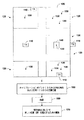
ここで図1を参照すると、信号特性に基づいて新しい位置(群)を判定する、本発明のシステムのためのキャリブレーション手順の外形を示してある。こうした新しい位置(群)は、領域100内部にあることが求められる。領域100は、建物、建物のフロア、あるいは1つまたは複数の送信機110による受信可能範囲をもつ他の任意の領域でよい。送信機110は、領域100の内部および外部に配置することができる。位置決めシステムが少なくとも(x,y)の位置を判定できるためには、領域100内でその信号特性を測定することができる少なくとも3つの送信機110がなければならない。こうした送信機110は、必須ではないが、たとえば、ネットワーク上に配置されたアクセスポイント(AP)送受信機とすることができる。ただし、ここでの説明においては、「送信装置」という語句および「送信機(群)」という用語は、ネットワーク上に配置されたあるいは配置されていない、および信号を送信する任意の装置を含むものと理解されたい。
Referring now to FIG. 1, the outline of a calibration procedure for the system of the present invention that determines a new position (group) based on signal characteristics is shown. These new positions (groups) are required to be inside the
領域100は区画120に分けられ、区画120は、たとえば建物内の部屋、廊下、またはラウンジを含むことができ、したがって大きさは可変でよい。あるいは区画120は、部屋の中の特定の位置でよい。送信機110は、区画120内に配置されている必要はない。さらに、区画120に分割されない領域100の追加区域があってもよい。
区画120は、1つまたは複数のキャリブレーションポイント130を含むことができる。キャリブレーション中に、すべてのキャリブレーションポイント130に受信機140が順次置かれていく。各キャリブレーションポイント130ごとに、受信可能なすべての送信機110の1つまたは複数の信号特性が記録される。一実施形態では、送信機110は、IEEE802.11標準に準拠する送受信機であり、信号特性は、キャリブレーションポイント130で測定される送信機110の信号強度である。また、各キャリブレーションポイント130ごとに、対応する区画120の識別が記録される。対応する区画120の識別は、たとえば地図から区画を選択するユーザによって指示されてもよい。すべての区画120の空間的位置も、キャリブレーションに必要とされる。こうした空間的位置は、各区画120の空間的な広がりの重心とすることができる。
The
別の実施形態では、各区画120ごとに唯一のキャリブレーションポイント130がある。キャリブレーションポイント130は、各区画120内部の既知の位置にある。次いで信号特性が複数回測定され、その間、受信機140は唯一のキャリブレーションポイント130に適当な順序で循環させられる。区画120の空間的位置は、キャリブレーションポイント130の空間的位置とみなされる。
In another embodiment, there is a
さらに別の実施形態では、各区画120ごとに複数のキャリブレーションポイント130がある。これらのキャリブレーションポイント130は、区画120全体に散在するように選択される。信号特性は、各キャリブレーションポイント130ごとに1回または複数回測定することができる。区画120の空間的位置は、区画120の重心とみなされる。
In yet another embodiment, there are
実施形態のいずれでも、動作150で、信号特性はすべてのキャリブレーションポイント130で受信機140によって測定され、すべての区画120にある空間的位置が集められる。次いで動作160で、このデータに対して回帰が実施される。回帰は、集められたデータに対して作用し、回帰関数を作成し、動作170で示すように、次にこの回帰関数を使用して、新しく測定された信号特性に基づいて領域100全体において新しい位置(群)を推定することができる。使うことができる。これらの新しい位置(群)は、キャリブレーションポイント130にある必要はない。実際、こうした位置は、区画120内にさえある必要はなく、キャリブレーション時に到達不可能な位置に現れることができる。
In any of the embodiments, at
ここで図2を参照すると、本発明による全体的なキャリブレーション処理のフロー図を示してある。説明を簡単にするために、図2の方法、および、たとえばフロー図の形の後続のどの方法も一連の動作として示し説明するが、本発明は動作の順序に限定されないことを理解されたい。というのは、いくつかの動作は、本発明によると、異なる順序で起こることもでき、かつ/または本明細書で示し説明する他の動作と同時に起こることもできるからである。たとえば、方法は代替的には、状態図など一連の相互に関連した状態またはイベントとして表すことができることが当業者には理解されよう。さらに、図示したすべての動作が、本発明による方法の実装に必要なわけではない。 Referring now to FIG. 2, there is shown a flow diagram of the overall calibration process according to the present invention. For ease of explanation, it should be understood that although the method of FIG. 2 and any subsequent method, for example in the form of a flow diagram, are shown and described as a series of operations, the invention is not limited to the order of operations. This is because, according to the present invention, some operations may occur in a different order and / or may occur concurrently with other operations shown and described herein. For example, those skilled in the art will appreciate that a method can alternatively be represented as a series of interrelated states or events, such as a state diagram. Moreover, not all illustrated acts may be required to implement a methodology in accordance with the present invention.
200で、受信機は、キャリブレーションポイント130に移動される。次いで202で、受信機の空間的位置が記録される。空間的位置の情報の記録は、各キャリブレーションポイントで実施する必要はないが、区画120のキャリブレーション中に一度だけ記録できることに留意されたい。受信機は次いで、204で示すように、その位置の1つまたは複数の送信機の信号強度を測定し記録する。206で、それ以外のキャリブレーションポイント130における信号強度を測定しなければならない場合、フローは200に戻って受信機を次のキャリブレーションポイント130に移動させ、そのキャリブレーションポイント130に対して測定および記録処理を続ける。他のキャリブレーションポイント130を測定しなくてよい場合、フローは206から208に進んで、回帰関数を作成する。この回帰関数は、回帰を介して学習を行う。学習用の組は、キャリブレーションポイント130および区画120の空間的位置で測定される信号強度を含む。次いで、領域100全体での信号強度に応じて(x,y)座標における位置を提供する回帰関数が決定される。あるいはまた、領域100が建物の複数のフロアに渡る場合、回帰関数は(x,y,z)座標を提供することができる。
At 200, the receiver is moved to the
ここで図3を参照すると、新しい位置(群)を判定する処理のフロー図を示してある。300で、受信機は、新しい位置がある大体の区域に移動される。この位置は、以前調査を行った位置でもあっても、初めて調査を行う位置であってもよい。次いで、302で示すように、信号強度が測定され記録される。信号は、領域100に関連づけられたどの送信機からも受信することができる。304で、受信機によって302で測定された信号強度に基づいて領域100内部の新しい位置(群)を推定するのに回帰関数が使用される。処理は次いで、停止ブロックに到達する。
Referring now to FIG. 3, a flow diagram of the process for determining a new position (group) is shown. At 300, the receiver is moved to the approximate area where the new location is. This position may be a position where a survey has been performed before or a position where a survey is performed for the first time. The signal strength is then measured and recorded, as indicated at 302. The signal can be received from any transmitter associated with
アルゴリズム
ここで図4を参照すると、本発明による、信号強度から(x,y)位置へのマッピングを決定する処理のより詳細なフロー図を示してある。400で、すべての区画120からの信号強度ベクトルが、K個のクラスタにクラスタ化される。402で、すべての信号強度ベクトルが、ベクトルの学習用の組およびテスト用の組に分けられる。404で、試していないシグマ(σ)の値が選択される。406で、カーネル行列が学習用の組から作成される。408で、線形システムが、アルファ(α)およびベータ(β)の係数について解かれる。410で、シグマ(σ)、アルファ(α)、およびベータ(β)の値が保存される。412で、シグマ(σ)、アルファ(α)、およびベータ(β)の値が、方程式(2)および(3)を用いて、テスト用の組で評価される。414で、最後のシグマ(σ)に到達したかどうか判定する。到達していない場合、フローは404の入力に戻って、試していない別のシグマ(σ)を選択する。到達している場合、フローは416に進んで、最良のシグマ(σ)、アルファ(α)、およびベータ(β)を保存する。
Algorithm Referring now to FIG. 4, there is shown a more detailed flow diagram of a process for determining a mapping from signal strength to (x, y) position according to the present invention. At 400, the signal strength vectors from all
以下で、アルゴリズムおよび関連する方程式を詳細に説明する。 In the following, the algorithm and associated equations are described in detail.
以下で説明する数学的処理の理解を容易にするために、キャリブレーション信号強度の読取り結果の各組は、ベクトルsiで指定され、iは、実質的にすべての部屋の位置における、実質的にすべてのキャリブレーションベクトルに索引をつける。各キャリブレーションベクトルは、そのベクトルが捕捉された位置を与える、対応する(xi,yi)をもつ。この位置は、区画120の空間的な広がりの重心でも、受信機が置かれているどの場所でもよい。各信号強度ベクトルsiは、複数の要素、すなわち領域100内で受信可能な各送信機ごとに1つの要素を有する。キャリブレーションポイント130で感知されなかった送信機に対応する、si中の要素には、実験を通して見ることのできた最小信号強度より1つ低い値が与えられている。信号強度は、WRAPI(Wireless Research Application Program Interface)ライブラリからdBm単位の整数として戻される。ここでdBm=10log10(ミリワット)である。
To facilitate understanding of the mathematical processing described below, each set of calibration signal strength readings is specified by a vector s i , where i is substantially equal to the position of all rooms. Index all calibration vectors. Each calibration vector has a corresponding (x i , y i ) that gives the position where the vector was captured. This position may be the center of gravity of the spatial extent of the
IEEE802.11に基づく従来の多くの位置決め研究では、位置測定タスクを分類問題として系統立てて説明しており、その目標は、信号強度ベクトルを別々の位置の組に分類することである。これは、確率的定式化を含み、すべての潜在的な位置に関する1組の確率が分類結果に与えられる。ただし、分類の定式化は、キャリブレーション段階に特定の部屋を完全にスキップするという目標には適していない。学習を行った分類装置(classifier)は、ある部屋を見たことがなければ、その部屋から発信されたものとしてデータを分類することはない。 Many conventional positioning studies based on IEEE 802.11 systematically describe position measurement tasks as a classification problem, the goal of which is to classify signal strength vectors into separate sets of positions. This includes a probabilistic formulation, where a set of probabilities for all potential locations is given to the classification result. However, the classification formulation is not suitable for the goal of completely skipping certain rooms during the calibration phase. A classifier that has learned does not classify data as having been transmitted from a room unless it has seen a room.
むしろ、本発明は、回帰を使って、信号強度ベクトル(群)を位置にマッピングする回帰関数を形成する。したがって、本発明は、キャリブレートされたことがない新しい位置に信号強度ベクトルをマッピングすることができる。依然として(回帰ではなく)分類が所望される場合、後処理検査を行って、もしあれば、どの部屋が推定された位置を含むか判定することができる。 Rather, the present invention uses regression to form a regression function that maps the signal strength vector (s) to locations. Thus, the present invention can map signal strength vectors to new locations that have never been calibrated. If classification is still desired (rather than regression), a post-processing check can be performed to determine which, if any, the estimated location contains.
以下で、図1の実施形態に従って測定された信号強度をどのようにして使って、信号強度ベクトルに応じて位置を与える回帰関数を生成するか説明し、その後でキャリブレーションベクトルの数を原則に基づいて減らし、キャリブレーションデータ量の削減が位置測定の正確さにどのように影響するか調べる。 In the following, it will be described how to use the signal strength measured according to the embodiment of FIG. 1 to generate a regression function that gives a position according to the signal strength vector, and then in principle the number of calibration vectors Find out how the reduction in calibration data affects the accuracy of position measurements.
回帰は、キャリブレーションベクトルsiおよび対応する部屋座標(xi,yi)に関数を当てはめる。本発明では、以下の公式を介して新しい位置(群)を推定するカーネル回帰を使用する。 The regression fits a function to the calibration vector s i and the corresponding room coordinates (x i , y i ). In the present invention, kernel regression is used to estimate the new position (s) via the following formula:

上式においてK(r)は選択されたカーネル関数であり、 Where K (r) is the selected kernel function,
![]()
![]()
は選択されたカーネル関数の重心であり、αjおよびβjは、キャリブレーションデータに基づく計算された重みである。観測された信号強度ベクトルsと格納された信号強度ベクトル Is the centroid of the selected kernel function, and α j and β j are the calculated weights based on the calibration data. Observed signal strength vector s and stored signal strength vector
![]()
![]()
の間のユークリッド距離rは、 The Euclidean distance r between
![]()
![]()
によって示される。オフセット(cx,cy)は、機械学習の分野において公知であるように、いくつかの方法で計算することができる。一実施形態では、オフセットは、簡単には学習用データの重心、すなわち Indicated by. The offset (c x , c y ) can be calculated in several ways, as is known in the field of machine learning. In one embodiment, the offset is simply the centroid of the training data, i.e.
であり、上式において、Nはキャリブレーションベクトルの数である(本明細書で提供する適用例では、この数は28,114である)。 Where N is the number of calibration vectors (in the application provided herein, this number is 28,114).
図1の実施形態では、カーネル関数は、等方性のガウスカーネル関数: In the embodiment of FIG. 1, the kernel function is an isotropic Gaussian kernel function:
であるように選択され、上式において、σは半径であり、rはユークリッド距離 Where σ is the radius and r is the Euclidean distance
![]()
![]()
である。 It is.
こうしたカーネル関数の選択はまた、基準パラメータであるシグマ(σ)の選択を必要とし、これについては後で説明する。さらに、M個のカーネル重心 Such kernel function selection also requires selection of the reference parameter, sigma (σ), which will be described later. In addition, M kernel centroids
![]()
![]()
の選択についても後で説明する。 The selection will be described later.
本発明では、最小二乗法を使って、キャリブレーションデータに基づいて重みαjおよびβjを計算する。αj(x座標向け)を計算するために、キャリブレーションデータとx(si)の間の二乗された誤差が以下の式で最小にされる。 In the present invention, the weights α j and β j are calculated based on the calibration data using the least square method. To calculate α j (for the x coordinate), the squared error between the calibration data and x (s i ) is minimized with the following equation:
上式において、 In the above formula,
![]()
![]()
である。αjに対する最小化により、ベクトルa=(α0,α1,...,αM−2,αM−1)Tに対して解くことができる線形方程式:
KTKa=KTx (5)
が得られる。ここで、KはKijのNxMの行列であり、x=(x0−cx,x1−cx,...,xN−2−cx,xN−1−cx)Tである。同じように、βjは、KTKβ=KTxから取得される。
It is. Linear equations that can be solved for the vector a = (α 0 , α 1 ,..., α M−2 , α M−1 ) T by minimizing for α j :
K T Ka = K T x (5)
Is obtained. Here, K is an NxM matrix of K ij , and x = (x 0 −c x , x 1 −c x ,..., X N−2 −c x , x N−1 −c x ) T It is. Similarly, β j is obtained from K T Kβ = K T x.
KTKはMxMの大きさであり、Mは格納された信号強度ベクトルのうち選択された数であることに留意されたい。KTKはカーネル行列である。可能な1つの選択は、各キャリブレーションポイントsiを、格納された信号強度ベクトルとして働かせ、M=Nとすることである。27,000より大きいM(図1の実施形態で使うように)を使って方程式(5)を解くには、コンピュータによる非常に多くの計算が必要である。さらに、M=Nのときに作成された回帰関数は、キャリブレーションポイント130の間で円滑に一般化することができない。その代わりに、信号強度のキャリブレーションベクトルを各位置においてクラスタ化し、クラスタの重心を、カーネルの重心として用いた。標準的なk平均アルゴリズムを用いて、各部屋におけるk=5の信号強度クラスタを計算すると、その結果、700個未満のカーネル重心が、検査フロアにあるすべての118部屋を表すことになる。 Note that K T K is a magnitude of M × M, where M is a selected number of stored signal strength vectors. K T K is a kernel matrix. One possible choice is to let each calibration point s i act as a stored signal strength vector, with M = N. Solving equation (5) with M greater than 27,000 (as used in the embodiment of FIG. 1) requires a great deal of computation by the computer. Furthermore, the regression function created when M = N cannot be generalized smoothly between calibration points 130. Instead, the signal strength calibration vectors were clustered at each position, and the cluster centroid was used as the kernel centroid. Using a standard k-means algorithm to calculate k = 5 signal strength clusters in each room, the result is that less than 700 kernel centroids represent all 118 rooms on the inspection floor.
キャリブレーションポイント130の位置が不確実であることがわかっている場合、方程式(4)の各項は、対応するキャリブレーションポイントの不確実性の分散の逆数によって、重みづけすることができる。当該分野において、これは不均一分散(heteroscedastic)回帰として知られる。
If it is known that the position of the
唯一残されている選択は、基準パラメータσに関するものであった。単純な線形探索を、σのとり得る値に対して実施した。各候補σごとに、重みaおよびβを、最初にキャリブレーションデータの70%を使って計算した。先ほどのデータとは異なる残りの30%を使って候補を評価した。システムは、(x,y)におけるrms距離の誤差が最も小さいσを選んだ。σの計算用に70/30の割合で分割するにもかかわらず、100%のキャリブレーションデータを、カーネルの中心用にクラスタ化を行うのに使った。 The only remaining choice was for the reference parameter σ. A simple linear search was performed on the possible values of σ. For each candidate σ, weights a and β were initially calculated using 70% of the calibration data. Candidates were evaluated using the remaining 30%, which is different from the previous data. The system chose σ with the smallest rms distance error at (x, y). Despite the 70/30 split for σ calculation, 100% calibration data was used to cluster for the kernel center.
先に示したように、任意選択のステップは、最後のいくつかの位置の結果を共に平均化し、ノイズを低下させることである。最後の10個の(x,y)の結果は、共に平均化された。 As indicated above, an optional step is to average the results of the last few positions together to reduce noise. The last 10 (x, y) results were averaged together.
上述したように、学習用データとは別個に、テスト用ベクトルの第2の組を数日間とった。区画120ごとに1つのキャリブレーションポイント130がとられる実施形態を用いると、第2の組は合計で、テスト用データとして働く25,457個の読取り結果となった。このデータをテストするとき、カーネル回帰方法は、約3.75メートルのrms誤差を生じた。rms誤差の計算は、当該分野において公知であり、従ってここには示さない。
As described above, apart from the learning data, the second set of test vectors was taken for several days. Using an embodiment where one
適用例
先に示したように、本発明の位置決めアルゴリズムは、既知の部屋の位置からとられた信号強度の学習用データの回帰に基づいて作用する。
Application Examples As described above, the positioning algorithm of the present invention operates based on regression of learning data of signal strength taken from a known room position.
ここで図5を参照すると、本発明のキャリブレーション処理の適用例に使用される、部屋502を含む一般的なオフィスのフロア500の配置図を示してある。フロア500は、132室の部屋502を含み、そのうち118は到達可能であった。フロア500の面積は約2,680平方メートルである。フロアを領域100とみなした。建物のフロア地図は、ポリゴン表現およびビットマップ両方として抽出された。すべての地図の座標は、実際のフロア座標としてメートルで表した。アルゴリズムは、118室の異なる部屋を有する1つのフロア500において評価された。
Referring now to FIG. 5, there is shown a layout of a
キャリブレーション作業の問題を調べると、各部屋においてほとんど時間が費やされなかったかのように、あるいは特定の部屋がスキップされたかのように、キャリブレーションデータの量が削減された。より広い部屋、たとえば会議室ではより多くの受信機位置が使われたので、118室の部屋は137の区画に分割された。受信機位置は、後述する図6に示したインターフェースを介して地図を使用して位置選択を行うことによって記録された。結果は、19.5平方メートルごとにキャリブレーション位置を示した。キャリブレーションのために、到達可能な各区画には、無線接続された受信機、たとえばログ記録プログラムを実行しているポータブルPCが入れられた。ログ記録プログラムは、WRAPIインターフェースを使って、目に見えるすべてのIEEE802.11送信機から信号強度を取得した。受信機は、各位置において約60秒間信号を測定した。さらに、受信機は、いくつかの異なった方向に向けられ、配向効果を要因から除いた。3.4Hzの走査レートが用いられ、各位置ごとに約200回の走査が行われた。各走査により、無線アクセスポイントの信号強度およびMAC(メディアアクセスコントローラ)アドレスの組を得た。平均して、無線通信インターフェースは、いつでも3.9個のAPを「見る」ことができた。先に示したように、信号強度読取り結果の第1の組は合計で27,796個であり、第2の組は、テスト用データとして働くように数日後にとられたものであり、合計25,457個であった。 Examining the calibration problem, the amount of calibration data was reduced as if little time was spent in each room, or as if a particular room was skipped. Since more receiver locations were used in larger rooms, eg conference rooms, 118 rooms were divided into 137 sections. The receiver position was recorded by performing position selection using a map via the interface shown in FIG. 6 described later. The result showed the calibration position every 19.5 square meters. For calibration, each reachable compartment contained a wirelessly connected receiver, such as a portable PC running a logging program. The logging program used the WRAPI interface to obtain signal strength from all visible IEEE 802.11 transmitters. The receiver measured the signal for about 60 seconds at each location. In addition, the receiver was oriented in several different directions, removing the orientation effect from the factor. A scan rate of 3.4 Hz was used and approximately 200 scans were performed for each position. Each scan yielded a set of wireless access point signal strength and MAC (Media Access Controller) address. On average, the wireless communication interface was able to “see” 3.9 APs at any time. As indicated above, the first set of signal strength readings totaled 27,796, and the second set was taken several days later to serve as test data, There were 25,457.
ノイズを低減し正確さを増す手段として、計算された位置ベクトルに平均化実行フィルタを適用した。フィルタは、サンプル10個分の長さであり、3.4Hzの走査レートで約2.9秒の遅延を含む。 An averaging filter was applied to the calculated position vector as a means of reducing noise and increasing accuracy. The filter is 10 samples long and includes a delay of about 2.9 seconds at a scan rate of 3.4 Hz.
時間を短くした影響をテストするために、キャリブレーションデータの最初のs秒を、同じ学習アルゴリズムを用いて処理し、次いでテスト用の組全体を用いてテストした。各位置において10秒しか時間を費やさなかった場合でさえ、正確さに重大な影響はなかった。10秒で、rms誤差は60秒の場合のrms誤差から約12%(すなわち0.45メートル)しか増加しなかった。3.4Hzのデータレートでは、10秒分のデータは、34個の信号強度ベクトルのみを生じた。このことは、キャリブレーション中に各位置で長い時間を費やす必要はないことを示す。 To test the effect of shortening the time, the first s seconds of the calibration data were processed using the same learning algorithm and then tested using the entire test set. Even if only 10 seconds were spent at each location, there was no significant impact on accuracy. At 10 seconds, the rms error increased only about 12% (ie, 0.45 meters) from the rms error at 60 seconds. At a data rate of 3.4 Hz, 10 seconds of data yielded only 34 signal strength vectors. This indicates that it is not necessary to spend a long time at each position during calibration.
キャリブレーション位置の数を、137か所の位置の元の完全な組から元の10%まで削減することによる影響をテストした。元のキャリブレーションの組からkか所の位置を選ぶために、元の位置においてk平均アルゴリズムを実行し、Kクラスタを作った。Kクラスタの重心に最も近いkか所の元の位置をキャリブレーション用に選んだ。判定を行うと、位置の数が減るのに従ってrms誤差が上昇した。しかし、位置の数が50%でも、rms誤差は20%(0.74メートル)しか上昇せず、位置の数が20%では、誤差は42%(1.59メートル)上昇した。元の位置の数の10%で、rms誤差は9.19メートルであり、100%での最良の結果より145%(5.44メートル)の上昇となった。したがって、このことは、キャリブレーションポイントのより密集した組に移ることに対して著しく減少する利益(diminishing return)があることを示す。この実験は、ある空間においてキャリブレーションポイントを、密集した組、たとえばすべての部屋の重心から開始して選び、k平均を使ってその組を代表的な下位サンプルにクラスタ化する方法も提案している。 The effect of reducing the number of calibration positions from the original complete set of 137 positions to the original 10% was tested. To select k locations from the original calibration set, a k-means algorithm was run at the original location to create a K cluster. The k original positions closest to the center of gravity of the K cluster were chosen for calibration. When the determination was made, the rms error increased as the number of positions decreased. However, even if the number of positions was 50%, the rms error increased only by 20% (0.74 meters), and when the number of positions was 20%, the error increased by 42% (1.59 meters). At 10% of the number of original positions, the rms error was 9.19 meters, an increase of 145% (5.44 meters) from the best results at 100%. This therefore indicates that there is a significant diminishing return for moving to a more dense set of calibration points. This experiment also proposes a method of selecting calibration points in a space starting from a dense set, eg, the center of gravity of all rooms, and clustering the set into representative subsamples using k-means. Yes.
さらに、正確さを少し低下させるだけで、各位置で費やされる時間および位置の数の両方を大幅に削減することができる。たとえば、40%に相当する位置で30秒を費やしても、rms誤差は約21%(3.75メートルから4.55メートルまで)しか上昇せず、さらにキャリブレーション作業は半分以上も減らされる。 Furthermore, both the time spent at each location and the number of locations can be significantly reduced with only a small reduction in accuracy. For example, spending 30 seconds at a position corresponding to 40% raises the rms error by only about 21% (from 3.75 meters to 4.55 meters) and further reduces the calibration work by more than half.
ここで図6を参照すると、キャリブレーションデータの、信号強度のログ記録を容易にするグラフィカルユーザインターフェース(GUI)600の例示的なスクリーンショットを示してある。GUI600は、フロア500およびそこにある部屋のフロア画像表現602の表示を容易にする。ユーザは、マウス、キーボード、または他の従来の入力装置を介してフロア表現602から部屋を選択することによって、受信機の位置を示す。さらに、信号強度サブウィンドウ604が提示されており、このウィンドウには、近くの送信機からの測定された信号強度の表現を表示する信号強度インディケータ作図605が提示される。たとえば、第1のバー606は、キャリブレート中の現在のフロアにある送信機から信号が受信されたことを示す第1の色または塗りつぶしパターンを含む。バー606に関連づけられるのは、データ608であり、このデータは、信号強度データ、部屋が位置するフロア、および送信機の部屋番号(すなわち、113/3/3327)を示す。この具体的な例において、送信機は、3階フロア(3)の建物番号(113)、部屋番号3327(画像として610でも示す)にあった。
Referring now to FIG. 6, an exemplary screenshot of a graphical user interface (GUI) 600 that facilitates logging of signal strength of calibration data is shown. The
第2のバー612は、キャリブレート中の現在のフロア以外のフロアにある送信機から受信された測定結果を示すのに使うことができる。バー612は、建物113の4階のフロアにある部屋4327である部屋113/4/4327に関連づけられる。GUIは、このようなインターフェース特徴を提供するために一般的に利用可能な、点滅するバー、およびテキスト、音声出力信号などを含む信号を測定するために、非常に様々な画像応答を提供するようにプログラムすることができることを理解されたい。 The second bar 612 can be used to show measurement results received from transmitters on floors other than the current floor being calibrated. Bar 612 is associated with room 113/4/4327, which is room 4327 on the fourth floor of building 113. The GUI will provide a wide variety of image responses to measure signals including blinking bars and text, audio output signals, etc. that are commonly available to provide such interface features. It should be understood that it can be programmed into.
インターフェース600は、ユーザが、地図拡大サブウィンドウを介してフロアの地図を拡大すること、およびフロア選択サブウィンドウを介してキャリブレーションのためのフロアを選択することを可能にする、位置入力サブウィンドウ614も含む。
The
インターフェース600は、信号検出用の走査レート(ヘルツ)を選択する走査制御サブウィンドウ616をさらに含む。ユーザは、ロギングのパスフィールド618を介して、受信装置上の位置にデータのログ記録を指示することもできる。ユーザは、対応するネットワークパスをパスフィールド618に入力することによって、リモートネットワークストレージロケーションを選択することもできる。入力が行われると、指定されたファイル位置にすべてのデータが自動的に格納される。
The
一見したところ、位置決めシステムに対する約3.75メートルというrms誤差は、第1の従来の実験において約2.94メートル、または第2の従来の実験に対しては約1メートルの中央値誤差を得ていた、以前に行われていた従来の研究よりもはるかに悪いように思われる。しかし、こうした従来のシステムはどちらも、はるかに多くのキャリブレーション作業を必要としていた。第1の従来の実験は、70か所のキャリブレーションポイントを有する約54室の部屋の外側の廊下を含んでいた。第2の従来の実験は、約1.5メートル(5フィート)離れたキャリブレーションポイントを有する廊下を含んでいた。対象的に、開示した例では、重心から重心へ平均約2.85メートルで間隔を開けた部屋にある、部屋ごとに1か所のキャリブレーションポイントを使った。他の作業でも、キャリブレーションポイントの位置が確実にわかるようにするのに非常に多くの注意を払った。上述した第1および第2の従来の実験は、注意深いキャリブレーションによって達成できることを示しているが、開示した方法は、現実的なキャリブレーションによって達成できることを示す。 At first glance, an rms error of about 3.75 meters for the positioning system yields a median error of about 2.94 meters in the first conventional experiment, or about 1 meter for the second conventional experiment. It seems to be much worse than the previous work that was done. However, both of these conventional systems required much more calibration work. The first conventional experiment included a corridor outside the room of about 54 rooms with 70 calibration points. The second prior experiment included a corridor with calibration points about 1.5 meters (5 feet) apart. In contrast, in the disclosed example, one calibration point was used per room in a room that was spaced an average of about 2.85 meters from centroid to centroid. In other work, much attention was paid to ensure that the position of the calibration point was known. Although the first and second conventional experiments described above show that it can be achieved by careful calibration, the disclosed method shows that it can be achieved by realistic calibration.
IEEE802.11に基づく位置決めシステムの採用に対する1つの障害は、キャリブレーション作業である。開示した例では、建物の1つのフロアにある118部屋をキャリブレートするのに、約4時間を費やした。これだけの量のキャリブレーションが本当に必要かどうか知ることが望ましい。具体的には、各部屋に費やす時間を減らし、訪問する部屋の数を減らすことによる影響を評価することが望ましい。元の学習用データの部分集合に対する学習により、時間および部屋の数を減らすことによる影響をシミュレートした。 One obstacle to adopting a positioning system based on IEEE 802.11 is calibration work. In the disclosed example, approximately 4 hours were spent calibrating 118 rooms on one floor of the building. It is desirable to know if this amount of calibration is really necessary. Specifically, it is desirable to evaluate the impact of reducing the time spent in each room and reducing the number of rooms visited. By learning a subset of the original training data, the effects of reducing time and number of rooms were simulated.
要するに、IEEE802.11に基づく位置決め用のキャリブレーションは、非常に冗長な場合がある。開示した適用例では、オフィスビルの1つのフロアが部屋の分解能までキャリブレートされ、これは、IEEE802.11の位置決めシステムの大規模な展開に期待されていることに近いものである。信号強度に応じて位置を補間するために動径基底関数を使うことによって、平均間隔が約3.27メートルの部屋において、約3.75メートルのrms誤差が達成された。問題を補間の1つとして公定化することによって、大部分の部屋をスキップしてキャリブレーション処理をより簡単にすることができる。さらに、最低限必要な時間を超えてより多くの時間を費やしても正確さはあまり向上しないので、各部屋に多くの時間を費やす必要はない。 In short, calibration for positioning based on IEEE 802.11 may be very redundant. In the disclosed application, one floor of an office building is calibrated to room resolution, which is close to what would be expected of a large scale deployment of an IEEE 802.11 positioning system. By using a radial basis function to interpolate position as a function of signal strength, an rms error of about 3.75 meters was achieved in a room with an average spacing of about 3.27 meters. By formalizing the problem as one of the interpolations, it is possible to skip most of the rooms and make the calibration process easier. In addition, spending more time beyond the minimum required time does not improve accuracy much, so there is no need to spend much time in each room.
別の実装形態では、様々なキャリブレーション位置でただ1つの受信機からの複数の送信機の強度を測定するのではなく、開示した本発明は、いくつかの受信機を既知の位置に固定することによって送信機を位置判定すること、およびただ1つの送信機の強度を様々なキャリブレーション位置で測定することに等しく適用可能である。後者は、送信機が音声の発信源(たとえば人間)であり、受信機が1組の音声マイクロホンである場合に適用可能である。 In another implementation, rather than measuring the strength of multiple transmitters from a single receiver at various calibration positions, the disclosed invention fixes several receivers at known positions. This is equally applicable to locating a transmitter and measuring the intensity of a single transmitter at various calibration positions. The latter is applicable when the transmitter is an audio source (eg, a human) and the receiver is a set of audio microphones.
さらに別の実施形態では、キャリブレーションおよび回帰は、信号強度に対して作用する必要はない。位相、自己相関、またはスペクトルなど様々な信号プロパティを使うことができる。回帰は、各プロパティ自体がスカラーでない場合でも、こうした代替的な信号プロパティにも等しくよく適用することができる。カーネル回帰システムへの入力はしたがって、1つのベクトルからなり、このベクトルは、共に付加されている信号プロパティを含む複数のベクトルを構成する。 In yet another embodiment, calibration and regression need not operate on signal strength. Various signal properties such as phase, autocorrelation, or spectrum can be used. Regression applies equally well to these alternative signal properties, even if each property itself is not a scalar. The input to the kernel regression system thus consists of a single vector, which constitutes a plurality of vectors that contain signal properties that are appended together.
ここで図7を参照すると、開示したアーキテクチャを実行するように動作可能なコンピュータのブロック図を示してある。本発明の様々な態様向けの付加的な状況を提供するために、図7および以下の説明では、本発明の様々な態様を実装することができる適切な計算機環境700の手短で、一般的な説明を提供することを意図している。上記説明では、1つまたは複数のコンピュータを実行することができるコンピュータ実行可能命令という一般的な状況において本発明を説明したが、本発明は他のプログラムモジュールとの組合せとしても、かつ/またはハードウェアおよびソフトウェアの組合せとしても実施できることが当業者には理解されよう。全般的には、プログラムモジュールは、特定のタスクを実施し、または特定の抽象データタイプを実装するルーチン、プログラム、構成要素、データ構造などを含む。さらに、発明性のある本方法は、他のコンピュータシステム構成と共に実施できることが当業者には理解されよう。他のコンピュータシステム構成には、シングルプロセッサコンピュータシステムまたはマルチプロセッサコンピュータシステム、ミニコンピュータ、メインフレームコンピュータ、ならびにパーソナルコンピュータ、ポータブル計算装置、マイクロプロセッサベースの家電製品またはプログラム可能な家電製品などがあり、それぞれが1つまたは複数の関連する装置に動作可能に結合することができる。図示した本発明の態様は、通信ネットワークを介してリンクされるリモート処理装置によって特定のタスクが実施される分散型計算機環境でも実施することができる。分散型計算機環境では、プログラムモジュールは、ローカルおよびリモートメモリ記憶装置両方に置くことができる。
Referring now to FIG. 7, a block diagram of a computer operable to implement the disclosed architecture is shown. To provide additional context for various aspects of the present invention, FIG. 7 and the following description provide a brief, general description of a
図7を再度参照すると、本発明の様々な態様を実装する例示的な環境700を示してあり、この環境は、コンピュータ702を含み、このコンピュータ702は、処理ユニット704、システムメモリ706、およびシステムバス708を含む。システムバス708は、システムメモリ706を含むがそれに限定されないシステム構成要素を処理ユニット704に結合する。デュアルマイクロプロセッサおよび他のマルチプロセッサアーキテクチャも、処理ユニット704として利用することができる。
Referring again to FIG. 7, an
システムバス708は、市販されている様々なバスアーキテクチャの任意のものを使用するメモリバスまたはメモリコントローラ、周辺バス、およびローカル・バスなどいくつかのタイプのバス構造のいずれでもよい。システムメモリ706は、読出し専用メモリ(ROM)710およびランダムアクセスメモリ(RAM)712を含む。基本入出力システム(BIOS)は、たとえば起動中にコンピュータ702内部の要素間の情報の転送を助ける基本ルーチンを含み、ROM710に格納される。
The
コンピュータ702は、たとえば、ハードディスクドライブ714、(たとえば取外し可能ディスク718からの読出しまたはそこへの書込みをするための)磁気ディスクドライブ716、および、(たとえばCD−ROMディスク722または他の光学媒体からの読出しまたはそこへの書込みを行う)光ディスクドライブ720をさらに含む。ハードディスクドライブ714、磁気ディスクドライブ716、および光ディスクドライブ720は、それぞれハードディスクドライブインターフェース724、磁気ディスクドライブインターフェース726、および光ドライブインターフェース728によって、システムバス708に接続することができる。ドライブおよびそれに関連するコンピュータ可読媒体は、データ、データ構造、コンピュータ実行可能命令などの不揮発性記憶装置を提供する。コンピュータ702に対して、ドライブおよび媒体は、同報通信プログラミングの記憶を適切なデジタル形式で調整する。上記のコンピュータ可読媒体の説明ではハードディスク、取外し可能な磁気ディスクおよびCDに言及したが、コンピュータ可読な他のタイプの媒体、たとえばジップドライブ、磁気カセット、フラッシュメモリカード、デジタル映像ディスク、カートリッジなども、例示的な動作環境において使うことができ、さらに、このようなどの媒体も本発明の方法を実施するコンピュータ実行可能命令を含むことができることが当業者には理解されよう。
The
オペレーティングシステム730、1つまたは複数のアプリケーションプログラム732、他のプログラムモジュール734、およびプログラムデータ736などいくつかのプログラムモジュールを、ドライブおよびRAM712に格納することができる。本発明は、市販されている様々なオペレーティングシステム、またはオペレーティングシステムの組合せを用いて実装できることが理解されよう。
Several program modules, such as
ユーザは、キーボード738、およびマウス740などの指示装置を介して、コマンドおよび情報をコンピュータ702に入力することができる。他の入力装置(図示せず)には、マイクロホン、IRリモコン、ジョイスティック、ゲーム用パッド、衛星パラボラアンテナ、スキャナなどがあり得る。こうしたおよび他の入力装置はしばしば、システムバス708に結合されるシリアルポートインターフェース742を介して処理ユニット704に接続されるが、他のインターフェース、たとえば並列ポート、ゲームポート、ユニバーサルシリアルバス(「USB」)、赤外線(IR)インターフェースによって接続することもできる。モニタ744または他のタイプの表示装置も、映像アダプタ746などのインターフェースを介してシステムバス708に接続される。モニタ744に加えて、コンピュータは通常、他の周辺出力装置(図示せず)、たとえばスピーカ、プリンタなども含むことができる。
A user may enter commands and information into the
コンピュータ702は、リモートコンピュータ(群)748など1つまたは複数のリモートコンピュータへの論理接続を使用してネットワーク接続された環境において動作することができる。リモートコンピュータ(群)748は、ワークステーション、サーバコンピュータ、ルータ、パーソナルコンピュータ、ポータブルコンピュータ、マイクロプロセッサベースの娯楽機器、ピア装置または他の共通ネットワークノードでよく、通常、コンピュータ702に関連して説明した要素の多くまたはすべてを含むが、簡潔にするために、メモリ記憶装置750のみを図示した。図示した論理接続は、ローカルエリアネットワーク(LAN)752およびワイドエリアネットワーク(WAN)754を含む。このようなネットワーク環境は、会社、企業規模のコンピュータネットワーク、イントラネットおよびインターネットにおいてよく見られる。
LANネットワーク環境において使われる場合、コンピュータ702は、ネットワークインターフェースまたはアダプタ756を介してローカルネットワーク752に接続される。アダプタ756は、LAN752への有線または無線通信を容易にすることができ、このLANには、無線アダプタ756と通信する無線アクセスポイントも配置することができる。WANネットワーク環境において使われる場合、コンピュータ702は通常、モデム758を含み、またはLAN上の通信サーバに接続され、または、たとえばインターネットなどのWAN754を介した通信を確立する他の手段を有する。モデム758は、内部にあっても外部にあってもよく、シリアルポートインターフェース742を介してシステムバス708に接続される。ネットワーク接続された環境では、コンピュータ702に関連して図示したプログラムモジュールまたはその一部は、リモートメモリ記憶装置750に格納することができる。図示したネットワーク接続は例示的なものであり、コンピュータ間の通信リンクを確立する他の手段も使うことができることが理解されよう。
When used in a LAN networking environment, the
図8は、本発明による例示的な計算機環境800の概略的なブロック図を示してある。システム800は、1つまたは複数のクライアント(群)802を含む。クライアント(群)802は、ハードウェアおよび/またはソフトウェア(たとえば、スレッド、処理、計算装置)でよい。クライアント(群)802は、たとえば、本発明を利用してクッキー(群)および/または関連する文脈情報を収容することができる。システム800は、1つまたは複数のサーバ(群)804も含む。サーバ(群)804は、ハードウェアおよび/またはソフトウェア(たとえば、スレッド、処理、計算装置)でよい。サーバ804は、たとえば、本発明を利用して変換を実施するためのスレッドを収容することができる。クライアント802とサーバ804の間の可能な1つの通信は、2つ以上のコンピュータ処理の間で伝送されるように適合されたデータパケットの形をとることができる。データパケットは、たとえば、クッキー(群)および/または関連する文脈情報を含むことができる。システム800は、クライアント(群)802とサーバ(群)804の間の通信を容易にするのに利用できる通信フレームワーク806を含む。通信は、有線(光ファイバを含む)および/または無線技術によって容易にすることができる。クライアント(群)802は、クライアント(群)802にローカルな情報(たとえば、クッキー(群)および/または関連する文脈情報)を格納するのに利用できる、1つまたは複数のクライアントデータストア(群)808に動作可能に接続される。同様に、サーバ(群)804は、サーバ804にローカルな情報を格納するのに利用できる、1つまたは複数のサーバデータストア(群)810に動作可能に接続される。
FIG. 8 shows a schematic block diagram of an
上記の説明内容は、本発明のいくつかの例を含む。当然ながら、本発明を説明するための構成要素または方法のあらゆる組合せを説明することはできないが、本発明のさらに多くの組合せおよび入替えが可能であることが当業者には理解できよう。したがって、本発明は、添付の特許請求の範囲の精神および範囲内であるこのようなすべての変更形態、修正形態および変形形態を包含することを意図したものである。さらに、詳細な説明または特許請求の範囲において「含む」という用語が使われている限りでは、「備える」は、使用される場合、請求項においては変化する言葉として解釈されるが、このような用語は、「備える」という用語と同様に包括的であることを意図している。 What has been described above includes examples of the present invention. Of course, not all combinations of components or methods for describing the invention can be described, but those skilled in the art will appreciate that many more combinations and substitutions of the invention are possible. Accordingly, the present invention is intended to embrace all such alterations, modifications and variations that fall within the spirit and scope of the appended claims. Further, to the extent that the term “comprising” is used in the detailed description or in the claims, “comprising”, when used, is to be interpreted as a variable word in the claims, but such The term is intended to be comprehensive as is the term “comprising”.
100 領域
110 送信機
120 区画
130 キャリブレーションポイント
140 受信機
500 典型的なオフィスフロア、フロア
502 部屋
600 グラフィカルユーザインターフェース(GUI)、インターフェース
602 フロアの画像表現、フロア表現
604 信号強度サブウィンドウ
605 信号強度インディケータの作図
606 バー
608 データ
614 位置入力サブウィンドウ
616 走査制御サブウィンドウ
618 ロギングのパスフィールド
700 計算機環境
702 コンピュータ
704 処理ユニット
706 システムメモリ
708 システムバス
710 読出し専用メモリ(ROM)
712 ランダムアクセスメモリ(RAM)
714 ハードディスクドライブ
716 磁気ディスクドライブ
718 取外し可能ディスク
720 光ディスクドライブ
722 CD−ROMディスク
724 ハードディスクドライブインターフェース
726 磁気ディスクドライブインターフェース
728 光学ドライブインターフェース
730 オペレーティングシステム
732 アプリケーションプログラム
734 他のプログラムモジュール
736 プログラムデータ
738 キーボード
740 マウス
742 シリアルポートインターフェース
744 モニタ
746 映像アダプタ
748 リモートコンピュータ(群)
750 メモリ記憶装置、リモートメモリ記憶装置
752 ローカルエリアネットワーク(LAN)
754 ワイドエリアネットワーク(WAN)
756 ネットワークインターフェース、ネットワークアダプタ、アダプタ、無線アダプタ
758 モデム
800 計算機環境
802 クライアント(群)
804 サーバ(群)
806 通信フレームワーク
808 クライアントデータストア(群)
810 サーバデータストア(群)
100
712 Random access memory (RAM)
714
750 Memory storage device, remote
754 Wide Area Network (WAN)
756 Network interface, network adapter, adapter,
804 server (s)
806
810 Server data store (s)
Claims (33)
識別された位置に関連する信号プロパティを測定すること、および
少なくとも部分的に前記信号プロパティに基づいたカーネル回帰関数であって、キャリブレーションデータの欠落に関わらず、観測された信号プロパティに応じて新しい位置(群)を推定する回帰関数を生成すること、
を含み、
前記カーネル回帰関数は、複数のカーネル関数を含み、各カーネル関数は、観測された信号プロパティのベクトルと格納された信号プロパティのベクトルとの間の差を計算し、格納されたプロパティの前記ベクトルは、測定された信号プロパティの複数のベクトルをクラスタ化しクラスタの重心をカーネルの重心として用いることによって計算されることを特徴とする方法。 A method of calibrating a system used to determine a new location (s) according to observed signal properties,
Measuring a signal property associated with the identified location, and a kernel regression function based at least in part on the signal property, new depending on the observed signal property, regardless of missing calibration data Generating a regression function to estimate the position (s),
Including
The kernel regression function includes a plurality of kernel functions, each kernel function calculates a difference between a vector of observed signal properties and a vector of stored signal properties, and the vector of stored properties is A method comprising: computing a plurality of vectors of measured signal properties and using the cluster centroid as the kernel centroid.
複数の前記基準パラメータ値を選択すること、
基準パラメータ値ごとに、前記基準パラメータ値を用いて前記信号プロパティの第1の部分集合に前記重みを適合させること、
前記第1の部分集合から独立したものである、信号プロパティの第2の部分集合に対して適合された前記重みを用いて前記回帰関数を評価すること、
前記信号プロパティの前記第2の部分集合における最小の位置誤差を前記回帰関数が取得する、最良の基準パラメータを選択すること、および
前記最良の基準パラメータおよび対応する重みを格納すること
によって決定されること
を特徴とする請求項1に記載の方法。 The regression function further includes weights and reference parameters, each kernel function depends on the reference parameters, and the reference parameters further include:
Selecting a plurality of said reference parameter values;
For each reference parameter value, adapting the weight to a first subset of the signal properties using the reference parameter value;
Evaluating the regression function using the weights adapted to a second subset of signal properties that are independent of the first subset;
Determined by selecting a best reference parameter for which the regression function obtains a minimum position error in the second subset of the signal properties, and storing the best reference parameter and corresponding weights The method according to claim 1, wherein:
少なくとも1つの無線送信装置にアクセスすること、
前記少なくとも1つの無線送信装置について信号強度データをロギングすること、
前記信号強度データに基づいたカーネル回帰関数を生成することと
を含み、
前記回帰関数は、観測された信号プロパティのベクトルと格納された信号プロパティのベクトルとの間の差を計算するために複数のカーネル関数を含み、前記複数のカーネル関数は、新しい位置(群)を、キャリブレーションデータの欠落に関わらず推定するために用いられ、この方法は、さらに、
格納されたプロパティの前記ベクトルを、測定された信号プロパティの複数のベクトルをクラスタ化して、クラスタの重心をカーネルの重心として用いることによって計算することを含むことを特徴とする方法。 A method for calibrating a position measurement system of a wireless device, comprising:
Accessing at least one wireless transmission device;
Logging signal strength data for the at least one wireless transmitter;
Generating a kernel regression function based on the signal strength data;
The regression function includes a plurality of kernel functions for calculating a difference between the observed signal property vector and the stored signal property vector, the plurality of kernel functions including a new position (s). , Used to estimate regardless of missing calibration data, this method further
A method comprising calculating the vector of stored properties by clustering a plurality of vectors of measured signal properties and using the cluster centroid as the kernel centroid.
識別された位置に関連する信号プロパティを測定する手段と、
キャリブレーションデータの欠落に関わらず信号強度を連続的な位置にマッピングするカーネル回帰関数を生成する手段と、
を備えており、前記カーネル回帰関数は、前記信号プロパティに少なくとも部分的に基づく複数のカーネル関数を含み、観測された信号プロパティと格納された信号プロパティとの差に応じて新しい位置(群)を推定し、格納されたプロパティの前記ベクトルは、測定された信号プロパティの複数のベクトルをクラスタ化しクラスタの重心をカーネルの重心として用いることによって計算されるすることを特徴とするシステム。 A positioning system that observes signal properties to determine a new position (group),
Means for measuring signal properties associated with the identified location;
Means for generating a kernel regression function that maps signal strength to continuous locations regardless of missing calibration data;
The kernel regression function includes a plurality of kernel functions based at least in part on the signal properties, and determines a new location (s) according to a difference between the observed signal properties and the stored signal properties. A system characterized in that the vector of estimated and stored properties is calculated by clustering a plurality of vectors of measured signal properties and using the cluster centroid as the kernel centroid.
識別された位置に関連する信号プロパティを測定する測定構成要素と、
前記信号プロパティに少なくとも部分的に基づくカーネル回帰関数を生成することによって、キャリブレーションデータの欠落に関わらず信号強度を連続的な位置にマッピングする回帰構成要素と、
を備えており、前記関数は、観測された信号プロパティデータに基づいて新しい位置(群)を推定し、複数のカーネル関数を含み、各カーネル関数が、観測された信号プロパティのベクトルと格納された信号プロパティのベクトルとの間の差を計算し、格納されたプロパティの前記ベクトルは、測定された信号プロパティの複数のベクトルをクラスタ化しクラスタの重心をカーネルの重心として用いることによって計算されることを特徴とするシステム。 A positioning system that uses observed signal properties to determine a new location (s),
A measurement component that measures signal properties associated with the identified location;
A regression component that maps signal strengths to continuous locations regardless of missing calibration data by generating a kernel regression function based at least in part on the signal properties;
The function estimates a new location (s) based on observed signal property data and includes a plurality of kernel functions, each kernel function stored with a vector of observed signal properties Calculate the difference between the vector of signal properties and the vector of stored properties is calculated by clustering multiple vectors of measured signal properties and using the cluster centroid as the kernel centroid Feature system.
識別された位置に関連する信号プロパティを測定する手段と、
前記測定された信号プロパティに少なくとも部分的に基づくカーネル回帰関数を生成する回帰手段と
を備えており、前記回帰関数は、複数のカーネル関数を含み、各カーネル関数は、キャリブレーションデータの欠落に関わらず、新しい位置(群)を推定するために、観測された信号プロパティのベクトルと格納された信号プロパティのベクトルとの間の差を計算し、前記開始手段は、
回帰アルゴリズムによって用いられる前記信号プロパティをクラスタ化してクラスタの重心がカーネルの重心と一致するようにする手段をさらに含むことを特徴とするコンピュータ。 A computer that calibrates a system that uses signal properties to estimate new location (s),
Means for measuring signal properties associated with the identified location;
And a regression means for generating a kernel regression function based at least in part on the measured signal property, wherein the regression function includes a plurality of kernel functions, each kernel function associated with missing calibration data. First, to estimate the new position (s), calculate the difference between the observed signal property vector and the stored signal property vector, the starting means comprising:
The computer further comprising means for clustering the signal properties used by the regression algorithm so that the centroid of the cluster coincides with the centroid of the kernel.
1つ又は複数の無線装置に関連づけられて識別された位置に関連する信号プロパティを測定することであって、測定された信号プロパティは、観測された信号プロパティであること、および
キャリブレーションデータの欠落に関わらず、前記観測された信号プロパティに応じて新しい無線装置に関連づけられた新しい位置(群)を推定する回帰関数を生成すること
を含み、
前記回帰関数は、複数のカーネル関数を含み、各カーネル関数は、測定された信号プロパティの複数のベクトルをクラスタ化しクラスタの重心をカーネルの重心として用いることによって、観測された信号プロパティのベクトルと格納された信号プロパティのベクトルとの間の差を計算することを特徴とする方法。 A method of calibrating a system used to determine a new location (s) according to observed signal properties,
Measuring a signal property associated with an identified location associated with one or more wireless devices, wherein the measured signal property is an observed signal property, and missing calibration data Regardless of generating a regression function that estimates a new location (s) associated with a new wireless device in accordance with the observed signal properties,
The regression function includes a plurality of kernel functions, each kernel function storing a vector of observed signal properties by clustering a plurality of vectors of measured signal properties and using the cluster centroid as the kernel centroid. Calculating a difference between a vector of measured signal properties.
ポータブルコンピュータを利用する1つ又は複数の無線装置に関連づけられて識別された位置に関連する信号プロパティを測定することであって、測定された信号プロパティは、観測された信号プロパティであること、および
前記ポータブルコンピュータ上の回帰関数であって、前記観測された信号プロパティに応じて新しい無線装置に関連づけられた新しい位置(群)を推定する回帰関数を生成すること
を含み、
前記回帰関数は、複数のカーネル関数を含み、各カーネル関数は、測定された信号プロパティの複数のベクトルをクラスタ化しクラスタの重心をカーネルの重心として用いることによって、観測された信号プロパティのベクトルと格納された信号プロパティのベクトルとの間の差を計算することを特徴とする方法。 A method of calibrating a system used to determine a new location (s) according to observed signal properties,
Measuring a signal property associated with an identified location associated with one or more wireless devices utilizing a portable computer, wherein the measured signal property is an observed signal property; and Generating a regression function on the portable computer that estimates a new location (s) associated with a new wireless device in response to the observed signal properties;
The regression function includes a plurality of kernel functions, each kernel function storing a vector of observed signal properties by clustering a plurality of vectors of measured signal properties and using the cluster centroid as the kernel centroid. Calculating a difference between a vector of measured signal properties.
Applications Claiming Priority (1)
| Application Number | Priority Date | Filing Date | Title |
|---|---|---|---|
| US10/423,093 US6992625B1 (en) | 2003-04-25 | 2003-04-25 | Calibration of a device location measurement system that utilizes wireless signal strengths |
Publications (3)
| Publication Number | Publication Date |
|---|---|
| JP2004325440A JP2004325440A (en) | 2004-11-18 |
| JP2004325440A5 JP2004325440A5 (en) | 2007-02-15 |
| JP4065437B2 true JP4065437B2 (en) | 2008-03-26 |
Family
ID=32962448
Family Applications (1)
| Application Number | Title | Priority Date | Filing Date |
|---|---|---|---|
| JP2004090393A Expired - Fee Related JP4065437B2 (en) | 2003-04-25 | 2004-03-25 | Calibration of equipment location systems using radio signal strength |
Country Status (5)
| Country | Link |
|---|---|
| US (3) | US6992625B1 (en) |
| EP (1) | EP1471688B1 (en) |
| JP (1) | JP4065437B2 (en) |
| KR (1) | KR100938047B1 (en) |
| CN (1) | CN100523860C (en) |
Families Citing this family (75)
| Publication number | Priority date | Publication date | Assignee | Title |
|---|---|---|---|---|
| US6992625B1 (en) * | 2003-04-25 | 2006-01-31 | Microsoft Corporation | Calibration of a device location measurement system that utilizes wireless signal strengths |
| US7250907B2 (en) * | 2003-06-30 | 2007-07-31 | Microsoft Corporation | System and methods for determining the location dynamics of a portable computing device |
| US7346359B2 (en) * | 2003-07-31 | 2008-03-18 | Pango Networks, Inc. | Method for RF fingerprinting |
| US7312752B2 (en) * | 2003-10-22 | 2007-12-25 | Awarepoint Corporation | Wireless position location and tracking system |
| US7209751B2 (en) * | 2004-03-30 | 2007-04-24 | Sony Corporation | System and method for proximity motion detection in a wireless network |
| US7760654B2 (en) * | 2004-09-24 | 2010-07-20 | Microsoft Corporation | Using a connected wireless computer as a conduit for a disconnected wireless computer |
| US7603460B2 (en) | 2004-09-24 | 2009-10-13 | Microsoft Corporation | Detecting and diagnosing performance problems in a wireless network through neighbor collaboration |
| US7317914B2 (en) * | 2004-09-24 | 2008-01-08 | Microsoft Corporation | Collaboratively locating disconnected clients and rogue access points in a wireless network |
| US7627537B2 (en) * | 2004-10-28 | 2009-12-01 | Intel Corporation | Score result reuse for Bayesian network structure learning |
| US20060094375A1 (en) * | 2004-11-03 | 2006-05-04 | Mcginley Robert | Portable survey inspection device |
| US7870081B2 (en) * | 2004-12-31 | 2011-01-11 | Intel Corporation | Parallelization of bayesian network structure learning |
| US7275014B1 (en) | 2005-02-10 | 2007-09-25 | At&T Corporation | Distributed graph layout for sensor node networks |
| US7403784B2 (en) * | 2005-03-10 | 2008-07-22 | Avaya Technology Corp. | Method and apparatus for positioning a set of terminals in an indoor wireless environment |
| US20070129084A1 (en) * | 2005-12-05 | 2007-06-07 | Nortel Networks Limited | Creating and recognizing user-defined locations using communication terminals |
| US7579952B2 (en) * | 2006-07-31 | 2009-08-25 | Caterpillar Inc. | System and method to identify and track RFID tags |
| KR100775858B1 (en) * | 2006-11-07 | 2007-11-13 | 한국전자통신연구원 | System and method for environment analysis for indoor wireless location |
| US7701393B2 (en) * | 2006-12-19 | 2010-04-20 | The Boeing Company | Radio frequency navigation using frequency response matching |
| EP2118810B1 (en) * | 2007-02-05 | 2012-08-15 | Andrew Corporation | System and method for optimizing location estimate of mobile unit |
| TWI353140B (en) | 2007-03-14 | 2011-11-21 | Quanta Comp Inc | Wireless communication system for automatically ge |
| US8077205B2 (en) * | 2007-06-14 | 2011-12-13 | Sony Corporation | Adaptive prediction of calibration parameters for color imaging devices |
| KR101236910B1 (en) | 2007-10-09 | 2013-02-25 | 삼성전자주식회사 | Method for performing operation related with other device through Near Field Communication and apparatus therfor |
| JP5203670B2 (en) | 2007-10-25 | 2013-06-05 | インターナショナル・ビジネス・マシーンズ・コーポレーション | Position estimation system, method and program |
| US8219116B1 (en) * | 2007-11-27 | 2012-07-10 | Google Inc. | Wireless base station location estimation |
| KR100954455B1 (en) * | 2008-01-28 | 2010-04-27 | 인하대학교 산학협력단 | Location recongnition method |
| KR100950941B1 (en) | 2008-02-04 | 2010-04-01 | 강릉원주대학교산학협력단 | System and method for estimating the location of a mobile node based on snooping node using a Received Signal Strength Indication |
| KR101058296B1 (en) * | 2008-09-10 | 2011-08-22 | 삼성에스디에스 주식회사 | Real time location tracking method and system for mobile devices |
| US8478642B2 (en) * | 2008-10-20 | 2013-07-02 | Carnegie Mellon University | System, method and device for predicting navigational decision-making behavior |
| TWI376521B (en) * | 2008-11-27 | 2012-11-11 | Ind Tech Res Inst | Collection and construction of training location data of positioning system and positioning method therefor |
| FR2944603B1 (en) * | 2009-04-17 | 2014-07-11 | Univ Troyes Technologie | SYSTEM AND METHOD FOR TARGET LOCATION BY A NETWORK OF RECEIVER TRANSMITTERS |
| US20100304762A1 (en) * | 2009-05-27 | 2010-12-02 | Bernard Joseph Hall | Indoor tracking system |
| US8350758B1 (en) * | 2009-10-01 | 2013-01-08 | Lighthouse Signal Systems LLC | Systems and methods for indoor geolocation based on yield of RF signals |
| US20110102267A1 (en) * | 2009-10-30 | 2011-05-05 | Janiszewski Tom J | Method and system for determining location information |
| US8565790B2 (en) | 2010-01-22 | 2013-10-22 | Qualcomm Incorporated | Methods and apparatuses for determining if access to a region is feasible or infeasible for a user of a mobile device |
| TWI427313B (en) * | 2010-02-09 | 2014-02-21 | Univ Nat Pingtung Sci & Tech | A method of positioning a rfid tag using spatial mesh algorithm |
| CN103119470B (en) * | 2010-07-21 | 2015-09-16 | 韩国贸易信息通信株式会社 | Carry out the system and method for the position-based service of indoor navigation |
| EP2418513A1 (en) | 2010-08-10 | 2012-02-15 | Astrium GmbH | Computing of robust and improved signal-in-space accuracy parameters in a regional or global navigation satellite system |
| JP5166502B2 (en) * | 2010-10-21 | 2013-03-21 | 株式会社日立製作所 | Positioning data management server and positioning data management method |
| US8565783B2 (en) * | 2010-11-24 | 2013-10-22 | Microsoft Corporation | Path progression matching for indoor positioning systems |
| US8981995B2 (en) | 2011-06-03 | 2015-03-17 | Microsoft Technology Licensing, Llc. | Low accuracy positional data by detecting improbable samples |
| US9470529B2 (en) | 2011-07-14 | 2016-10-18 | Microsoft Technology Licensing, Llc | Activating and deactivating sensors for dead reckoning |
| US9464903B2 (en) | 2011-07-14 | 2016-10-11 | Microsoft Technology Licensing, Llc | Crowd sourcing based on dead reckoning |
| US9942698B2 (en) | 2011-08-09 | 2018-04-10 | Blackberry Limited | Harvesting communication parameter observations in GNSS-denied environments |
| US10184798B2 (en) | 2011-10-28 | 2019-01-22 | Microsoft Technology Licensing, Llc | Multi-stage dead reckoning for crowd sourcing |
| US9429657B2 (en) | 2011-12-14 | 2016-08-30 | Microsoft Technology Licensing, Llc | Power efficient activation of a device movement sensor module |
| US20140044005A1 (en) * | 2012-01-19 | 2014-02-13 | Xirrus, Inc. | System and method for conducting wireless site surveys using wireless network design criteria |
| EP2825900A1 (en) * | 2012-03-15 | 2015-01-21 | Nokia Corporation | Supporting storage of data |
| CN104285377A (en) | 2012-03-15 | 2015-01-14 | 诺基亚公司 | Encoding and decoding of data |
| JP5979945B2 (en) | 2012-04-09 | 2016-08-31 | 任天堂株式会社 | Information processing program, information processing apparatus, information processing system, and information processing method |
| US9817125B2 (en) | 2012-09-07 | 2017-11-14 | Microsoft Technology Licensing, Llc | Estimating and predicting structures proximate to a mobile device |
| TWI489126B (en) * | 2012-12-19 | 2015-06-21 | Ind Tech Res Inst | System and method for dynamic correction of wireless signal strength |
| US9674655B2 (en) * | 2013-01-03 | 2017-06-06 | Cinarra Systems | Methods and systems for dynamic detection of consumer venue walk-ins |
| US20140297485A1 (en) * | 2013-03-29 | 2014-10-02 | Lexmark International, Inc. | Initial Calibration of Asset To-Be-Tracked |
| WO2015004812A1 (en) * | 2013-07-12 | 2015-01-15 | 三菱電機株式会社 | Network system, portable terminal device, and method for specifying device |
| KR101466514B1 (en) * | 2013-11-27 | 2014-11-28 | 한양대학교 산학협력단 | Positioning method and apparatus |
| US20150192658A1 (en) * | 2014-01-07 | 2015-07-09 | OmniTrail Technologies | Systems and methods for mobile device microlocation |
| US9485746B2 (en) * | 2014-06-03 | 2016-11-01 | Cisco Technology, Inc. | Location classification accuracy for devices inside and outside of a deployment area |
| JP6204889B2 (en) * | 2014-09-01 | 2017-09-27 | 日本電信電話株式会社 | COMMUNICATION AREA ESTIMATION SYSTEM, SERVER DEVICE, COMMUNICATION AREA ESTIMATION METHOD, AND COMMUNICATION AREA ESTIMATION PROGRAM |
| US9131403B1 (en) * | 2014-09-25 | 2015-09-08 | Ibwave Solutions Inc. | Method, computing device and computer program product for visual representation of RF propagation |
| TWI544822B (en) * | 2014-12-17 | 2016-08-01 | 緯創資通股份有限公司 | Signal strength distribution establishing method and wireless positioning system |
| JP6800881B2 (en) * | 2015-03-30 | 2020-12-16 | アフェロ インコーポレイテッドAfero, Inc. | Systems and methods for accurately detecting the user's position in the IoT system |
| CN105890580B (en) * | 2016-04-06 | 2018-01-30 | 马嘉伦 | A kind of interior space mapping system and mapping method |
| US10200810B2 (en) | 2016-06-12 | 2019-02-05 | Apple Inc. | Proactive actions on mobile device using uniquely-identifiable and unlabeled locations |
| US10244360B2 (en) | 2016-06-12 | 2019-03-26 | Apple Inc. | Determining location of mobile device using sensor space to physical space mapping |
| US10091303B1 (en) | 2016-06-12 | 2018-10-02 | Apple Inc. | Using in-home location awareness |
| US10117046B2 (en) | 2016-06-12 | 2018-10-30 | Apple Inc. | Discrete location classification |
| CN106793067A (en) * | 2016-11-29 | 2017-05-31 | 上海斐讯数据通信技术有限公司 | A kind of many floor indoor orientation methods and server based on joint network |
| FR3064074B1 (en) * | 2017-03-15 | 2019-05-03 | Sigfox | METHOD AND SYSTEM FOR GEOLOCATING A TERMINAL OF A WIRELESS COMMUNICATION SYSTEM |
| WO2019152849A1 (en) | 2018-02-02 | 2019-08-08 | Cornell University | Channel charting in wireless systems |
| JP2019144120A (en) * | 2018-02-21 | 2019-08-29 | 国立大学法人九州工業大学 | Indoor position estimation system, indoor position estimation method, and program for executing indoor position estimation method |
| US10382152B1 (en) * | 2018-06-29 | 2019-08-13 | IBT Connect R&D, LLC | Spectrum monitor system and apparatus for radio coverage testing |
| US10945190B2 (en) | 2019-01-04 | 2021-03-09 | Apple Inc. | Predictive routing based on microlocation |
| US11567186B2 (en) | 2019-03-19 | 2023-01-31 | Kabushiki Kaisha Toshiba | Compensating radio tracking with comparison to image based tracking |
| CN110213733B (en) * | 2019-05-23 | 2022-07-19 | 武汉金牛经济发展有限公司 | Internet of things system of electromagnetic hot melting welding machine |
| CN114485916B (en) * | 2022-01-12 | 2023-01-17 | 广州声博士声学技术有限公司 | Environmental noise monitoring method and system, computer equipment and storage medium |
| US11922000B2 (en) * | 2022-03-29 | 2024-03-05 | At&T Mobility Ii Llc | Method and apparatus for generating a venue map from a digital image |
Family Cites Families (51)
| Publication number | Priority date | Publication date | Assignee | Title |
|---|---|---|---|---|
| NO940977L (en) | 1993-04-06 | 1994-10-05 | Alcatel Str Ag | Method and apparatus for ensuring the quality of service in a mobile radio system |
| SE500769C2 (en) * | 1993-06-21 | 1994-08-29 | Televerket | Procedure for locating mobile stations in digital telecommunications networks |
| US5812865A (en) * | 1993-12-03 | 1998-09-22 | Xerox Corporation | Specifying and establishing communication data paths between particular media devices in multiple media device computing systems based on context of a user or users |
| US5493692A (en) * | 1993-12-03 | 1996-02-20 | Xerox Corporation | Selective delivery of electronic messages in a multiple computer system based on context and environment of a user |
| US5555376A (en) * | 1993-12-03 | 1996-09-10 | Xerox Corporation | Method for granting a user request having locational and contextual attributes consistent with user policies for devices having locational attributes consistent with the user request |
| US5602903A (en) * | 1994-09-28 | 1997-02-11 | Us West Technologies, Inc. | Positioning system and method |
| GB2311697B (en) * | 1996-03-22 | 1999-07-28 | Matsushita Electric Ind Co Ltd | Wireless communication system and method and system for detection of position of radio mobile station |
| US6035104A (en) | 1996-06-28 | 2000-03-07 | Data Link Systems Corp. | Method and apparatus for managing electronic documents by alerting a subscriber at a destination other than the primary destination |
| US6108557A (en) * | 1997-01-08 | 2000-08-22 | Us Wireless Corporation | Signature matching for location determination in wireless communication systems |
| US6084546A (en) * | 1997-01-08 | 2000-07-04 | Us Wireless Corporation | Location determination in wireless communication systems using velocity information |
| US6112095A (en) | 1997-01-08 | 2000-08-29 | Us Wireless Corporation | Signature matching for location determination in wireless communication systems |
| FI105005B (en) | 1997-05-13 | 2000-05-15 | Nokia Networks Oy | Method of estimating the speed of a terminal device, method of cell selection and radio system |
| US6052598A (en) * | 1997-09-30 | 2000-04-18 | At&T Corp | Method for predicting the location of a mobile station in a mobile communications network |
| KR100250477B1 (en) * | 1997-12-06 | 2000-04-01 | 정선종 | Location tracking method of mobile terminal using radio lan |
| US6161018A (en) * | 1998-02-27 | 2000-12-12 | Motorola, Inc. | Method and system for estimating a subscriber's location in a wireless communication system service area |
| US6393294B1 (en) * | 1998-09-22 | 2002-05-21 | Polaris Wireless, Inc. | Location determination using RF fingerprinting |
| US6269246B1 (en) * | 1998-09-22 | 2001-07-31 | Ppm, Inc. | Location determination using RF fingerprinting |
| US6266014B1 (en) | 1998-10-09 | 2001-07-24 | Cell-Loc Inc. | Methods and apparatus to position a mobile receiver using downlink signals part IV |
| JP4557429B2 (en) * | 1998-11-24 | 2010-10-06 | インテル・コーポレーション | Method and apparatus for calibrating a wireless communication station having an array antenna |
| US7076737B2 (en) * | 1998-12-18 | 2006-07-11 | Tangis Corporation | Thematic response to a computer user's context, such as by a wearable personal computer |
| US6801223B1 (en) * | 1998-12-18 | 2004-10-05 | Tangis Corporation | Managing interactions between computer users' context models |
| US6842877B2 (en) * | 1998-12-18 | 2005-01-11 | Tangis Corporation | Contextual responses based on automated learning techniques |
| US6513046B1 (en) * | 1999-12-15 | 2003-01-28 | Tangis Corporation | Storing and recalling information to augment human memories |
| US6747675B1 (en) * | 1998-12-18 | 2004-06-08 | Tangis Corporation | Mediating conflicts in computer user's context data |
| US7137069B2 (en) * | 1998-12-18 | 2006-11-14 | Tangis Corporation | Thematic response to a computer user's context, such as by a wearable personal computer |
| US7107539B2 (en) * | 1998-12-18 | 2006-09-12 | Tangis Corporation | Thematic response to a computer user's context, such as by a wearable personal computer |
| US6812937B1 (en) * | 1998-12-18 | 2004-11-02 | Tangis Corporation | Supplying enhanced computer user's context data |
| US6791580B1 (en) * | 1998-12-18 | 2004-09-14 | Tangis Corporation | Supplying notifications related to supply and consumption of user context data |
| US6466232B1 (en) * | 1998-12-18 | 2002-10-15 | Tangis Corporation | Method and system for controlling presentation of information to a user based on the user's condition |
| US7055101B2 (en) * | 1998-12-18 | 2006-05-30 | Tangis Corporation | Thematic response to a computer user's context, such as by a wearable personal computer |
| JP3607516B2 (en) * | 1999-01-20 | 2005-01-05 | 松下電器産業株式会社 | Mobile map matching device |
| US6330429B1 (en) | 1999-04-14 | 2001-12-11 | Lucent Technologies, Inc. | Channel grouping system and method for a wireless communications system |
| US6263208B1 (en) | 1999-05-28 | 2001-07-17 | Lucent Technologies Inc. | Geolocation estimation method for CDMA terminals based on pilot strength measurements |
| US6535833B1 (en) | 1999-11-22 | 2003-03-18 | Nokia Mobile Phones Ltd. | Method and apparatus for filtering measurements used in a generalized positioning system |
| EP1109031A1 (en) | 1999-12-10 | 2001-06-20 | Ascom Systec AG | Method and apparatus to localise a mobile terminal |
| JP2002160185A (en) * | 2000-03-31 | 2002-06-04 | Sony Corp | Robot device, behavior controlling method for robot device and device and method for detecting external force |
| WO2001075676A2 (en) * | 2000-04-02 | 2001-10-11 | Tangis Corporation | Soliciting information based on a computer user's context |
| US20020054130A1 (en) * | 2000-10-16 | 2002-05-09 | Abbott Kenneth H. | Dynamically displaying current status of tasks |
| WO2002033541A2 (en) * | 2000-10-16 | 2002-04-25 | Tangis Corporation | Dynamically determining appropriate computer interfaces |
| US20020044152A1 (en) * | 2000-10-16 | 2002-04-18 | Abbott Kenneth H. | Dynamic integration of computer generated and real world images |
| EP1205331B1 (en) | 2000-11-14 | 2005-09-07 | Nissan Motor Company, Limited | Driving force control apparatus |
| FI111901B (en) * | 2000-12-29 | 2003-09-30 | Ekahau Oy | Estimation of position in wireless communication networks |
| JP4513219B2 (en) * | 2001-03-06 | 2010-07-28 | 住友電気工業株式会社 | Prefix nonlinear distortion compensator |
| JP2003004835A (en) | 2001-06-18 | 2003-01-08 | Teruya:Kk | Method for measuring position by electric field strength |
| ATE365337T1 (en) | 2001-09-05 | 2007-07-15 | Newbury Networks Inc | POSITION DETECTION AND LOCATION TRACKING IN A WIRELESS NETWORK |
| US7030814B2 (en) * | 2001-09-07 | 2006-04-18 | Sirf Technology, Inc. | System and method to estimate the location of a receiver in a multi-path environment |
| JP3536094B2 (en) * | 2001-09-07 | 2004-06-07 | 独立行政法人通信総合研究所 | Multilevel modulation equalization method and equalizer using the same |
| US6873852B2 (en) * | 2002-01-10 | 2005-03-29 | Telefonaktiebolaget Lm Ericsson (Publ) | System and method of estimating the position of a mobile terminal in a radio telecommunications network |
| US6839027B2 (en) * | 2002-11-15 | 2005-01-04 | Microsoft Corporation | Location measurement process for radio-frequency badges employing path constraints |
| US7747307B2 (en) * | 2003-03-04 | 2010-06-29 | Calypso Medical Technologies, Inc. | Method and system for marker localization |
| US6992625B1 (en) * | 2003-04-25 | 2006-01-31 | Microsoft Corporation | Calibration of a device location measurement system that utilizes wireless signal strengths |
-
2003
- 2003-04-25 US US10/423,093 patent/US6992625B1/en not_active Expired - Lifetime
-
2004
- 2004-03-25 EP EP04007258.9A patent/EP1471688B1/en not_active Expired - Lifetime
- 2004-03-25 JP JP2004090393A patent/JP4065437B2/en not_active Expired - Fee Related
- 2004-04-14 KR KR1020040025779A patent/KR100938047B1/en not_active IP Right Cessation
- 2004-04-26 CN CNB2004100434011A patent/CN100523860C/en not_active Expired - Fee Related
-
2006
- 2006-01-30 US US11/342,515 patent/US7233286B2/en not_active Expired - Fee Related
-
2007
- 2007-06-14 US US11/763,422 patent/US7411549B2/en not_active Expired - Fee Related
Also Published As
| Publication number | Publication date |
|---|---|
| KR100938047B1 (en) | 2010-01-21 |
| EP1471688A3 (en) | 2008-05-07 |
| CN100523860C (en) | 2009-08-05 |
| JP2004325440A (en) | 2004-11-18 |
| EP1471688A2 (en) | 2004-10-27 |
| US7233286B2 (en) | 2007-06-19 |
| US7411549B2 (en) | 2008-08-12 |
| US20070241963A1 (en) | 2007-10-18 |
| CN1570664A (en) | 2005-01-26 |
| US20060119516A1 (en) | 2006-06-08 |
| EP1471688B1 (en) | 2015-04-15 |
| US6992625B1 (en) | 2006-01-31 |
| KR20040092414A (en) | 2004-11-03 |
Similar Documents
| Publication | Publication Date | Title |
|---|---|---|
| JP4065437B2 (en) | Calibration of equipment location systems using radio signal strength | |
| JP5165181B2 (en) | System and method for determining the location and dynamics of portable computer devices | |
| US9217788B2 (en) | Location and tracking system | |
| Krumm et al. | LOCADIO: Inferring Motion and Location from Wi-Fi Signal Strengths. | |
| US9763035B2 (en) | System, method and computer program for anonymous localization | |
| EP3108706B1 (en) | Localization of a wireless user equipmentdevice in a target zone | |
| US10057725B2 (en) | Sensor-based geolocation of a user device | |
| JP2005525003A (en) | Location detection and location tracking in wireless networks | |
| JP2015531053A (en) | System, method, and computer program for dynamically creating a radio map | |
| WO2013000073A9 (en) | An improved system and method for wireless positioning in wireless network-enabled environments | |
| US20170160375A1 (en) | Estimation of a level for an observation data set | |
| US8922433B2 (en) | Unsupervised learning and location systems for tracking in wireless communication systems | |
| Pan et al. | Map-aided and UWB-based anchor placement method in indoor localization | |
| Lemic et al. | Toward extrapolation of wifi fingerprinting performance across environments | |
| Zdruba et al. | Monte Carlo sampling based in-home location tracking with minimal RF infrastructure requirements | |
| JP7353495B2 (en) | Infrastructure-free RF tracking in dynamic indoor environments | |
| CN110856255B (en) | Anti-difference position fingerprint positioning method | |
| Trogh et al. | Advanced indoor localisation based on the Viterbi algorithm and semantic data | |
| Ko et al. | A proactive indoor positioning system in randomly deployed dense WiFi networks | |
| Alsehly | Adaptive indoor positioning system based on locating globally deployed WiFi signal sources | |
| Achutegui Roncal | Particle filters for tracking in wireless sensor networks | |
| Roncal | Particle filters for tracking in wireless sensor networks |
Legal Events
| Date | Code | Title | Description |
|---|---|---|---|
| RD03 | Notification of appointment of power of attorney |
Free format text: JAPANESE INTERMEDIATE CODE: A7423 Effective date: 20061201 |
|
| RD04 | Notification of resignation of power of attorney |
Free format text: JAPANESE INTERMEDIATE CODE: A7424 Effective date: 20061204 |
|
| A521 | Request for written amendment filed |
Free format text: JAPANESE INTERMEDIATE CODE: A523 Effective date: 20061222 |
|
| A621 | Written request for application examination |
Free format text: JAPANESE INTERMEDIATE CODE: A621 Effective date: 20061222 |
|
| A871 | Explanation of circumstances concerning accelerated examination |
Free format text: JAPANESE INTERMEDIATE CODE: A871 Effective date: 20061222 |
|
| A975 | Report on accelerated examination |
Free format text: JAPANESE INTERMEDIATE CODE: A971005 Effective date: 20070116 |
|
| A131 | Notification of reasons for refusal |
Free format text: JAPANESE INTERMEDIATE CODE: A131 Effective date: 20070123 |
|
| A521 | Request for written amendment filed |
Free format text: JAPANESE INTERMEDIATE CODE: A523 Effective date: 20070423 |
|
| A02 | Decision of refusal |
Free format text: JAPANESE INTERMEDIATE CODE: A02 Effective date: 20070524 |
|
| A521 | Request for written amendment filed |
Free format text: JAPANESE INTERMEDIATE CODE: A523 Effective date: 20070921 |
|
| A911 | Transfer to examiner for re-examination before appeal (zenchi) |
Free format text: JAPANESE INTERMEDIATE CODE: A911 Effective date: 20071106 |
|
| TRDD | Decision of grant or rejection written | ||
| A01 | Written decision to grant a patent or to grant a registration (utility model) |
Free format text: JAPANESE INTERMEDIATE CODE: A01 Effective date: 20071214 |
|
| A61 | First payment of annual fees (during grant procedure) |
Free format text: JAPANESE INTERMEDIATE CODE: A61 Effective date: 20080104 |
|
| R150 | Certificate of patent or registration of utility model |
Ref document number: 4065437 Country of ref document: JP Free format text: JAPANESE INTERMEDIATE CODE: R150 Free format text: JAPANESE INTERMEDIATE CODE: R150 |
|
| FPAY | Renewal fee payment (event date is renewal date of database) |
Free format text: PAYMENT UNTIL: 20110111 Year of fee payment: 3 |
|
| FPAY | Renewal fee payment (event date is renewal date of database) |
Free format text: PAYMENT UNTIL: 20110111 Year of fee payment: 3 |
|
| FPAY | Renewal fee payment (event date is renewal date of database) |
Free format text: PAYMENT UNTIL: 20120111 Year of fee payment: 4 |
|
| R250 | Receipt of annual fees |
Free format text: JAPANESE INTERMEDIATE CODE: R250 |
|
| FPAY | Renewal fee payment (event date is renewal date of database) |
Free format text: PAYMENT UNTIL: 20130111 Year of fee payment: 5 |
|
| R250 | Receipt of annual fees |
Free format text: JAPANESE INTERMEDIATE CODE: R250 |
|
| R250 | Receipt of annual fees |
Free format text: JAPANESE INTERMEDIATE CODE: R250 |
|
| R250 | Receipt of annual fees |
Free format text: JAPANESE INTERMEDIATE CODE: R250 |
|
| R250 | Receipt of annual fees |
Free format text: JAPANESE INTERMEDIATE CODE: R250 |
|
| S111 | Request for change of ownership or part of ownership |
Free format text: JAPANESE INTERMEDIATE CODE: R313113 |
|
| R350 | Written notification of registration of transfer |
Free format text: JAPANESE INTERMEDIATE CODE: R350 |
|
| R250 | Receipt of annual fees |
Free format text: JAPANESE INTERMEDIATE CODE: R250 |
|
| R250 | Receipt of annual fees |
Free format text: JAPANESE INTERMEDIATE CODE: R250 |
|
| R250 | Receipt of annual fees |
Free format text: JAPANESE INTERMEDIATE CODE: R250 |
|
| LAPS | Cancellation because of no payment of annual fees |