JP4057159B2 - Powder distribution device - Google Patents
Powder distribution device Download PDFInfo
- Publication number
- JP4057159B2 JP4057159B2 JP25622498A JP25622498A JP4057159B2 JP 4057159 B2 JP4057159 B2 JP 4057159B2 JP 25622498 A JP25622498 A JP 25622498A JP 25622498 A JP25622498 A JP 25622498A JP 4057159 B2 JP4057159 B2 JP 4057159B2
- Authority
- JP
- Japan
- Prior art keywords
- powder
- distribution tray
- support ring
- roller
- distribution
- Prior art date
- Legal status (The legal status is an assumption and is not a legal conclusion. Google has not performed a legal analysis and makes no representation as to the accuracy of the status listed.)
- Expired - Fee Related
Links
Images


Classifications
-
- B—PERFORMING OPERATIONS; TRANSPORTING
- B65—CONVEYING; PACKING; STORING; HANDLING THIN OR FILAMENTARY MATERIAL
- B65B—MACHINES, APPARATUS OR DEVICES FOR, OR METHODS OF, PACKAGING ARTICLES OR MATERIALS; UNPACKING
- B65B1/00—Packaging fluent solid material, e.g. powders, granular or loose fibrous material, loose masses of small articles, in individual containers or receptacles, e.g. bags, sacks, boxes, cartons, cans, or jars
- B65B1/04—Methods of, or means for, filling the material into the containers or receptacles
- B65B1/10—Methods of, or means for, filling the material into the containers or receptacles by rotary feeders
-
- B—PERFORMING OPERATIONS; TRANSPORTING
- B65—CONVEYING; PACKING; STORING; HANDLING THIN OR FILAMENTARY MATERIAL
- B65B—MACHINES, APPARATUS OR DEVICES FOR, OR METHODS OF, PACKAGING ARTICLES OR MATERIALS; UNPACKING
- B65B1/00—Packaging fluent solid material, e.g. powders, granular or loose fibrous material, loose masses of small articles, in individual containers or receptacles, e.g. bags, sacks, boxes, cartons, cans, or jars
- B65B1/04—Methods of, or means for, filling the material into the containers or receptacles
-
- B—PERFORMING OPERATIONS; TRANSPORTING
- B65—CONVEYING; PACKING; STORING; HANDLING THIN OR FILAMENTARY MATERIAL
- B65B—MACHINES, APPARATUS OR DEVICES FOR, OR METHODS OF, PACKAGING ARTICLES OR MATERIALS; UNPACKING
- B65B1/00—Packaging fluent solid material, e.g. powders, granular or loose fibrous material, loose masses of small articles, in individual containers or receptacles, e.g. bags, sacks, boxes, cartons, cans, or jars
- B65B1/30—Devices or methods for controlling or determining the quantity or quality or the material fed or filled
Description
【0001】
【発明の属する技術分野】
本発明は、処方された散薬を1服用づつに包装するため、散薬を分配皿に分配した後、掻き出し装置で掻き出して分割する散薬分配装置に関する。
【0002】
【従来の技術】
従来の散薬分配装置では、掻き出し装置の掻き出し方向が分配皿の回転軸に対して外周方向へ掻き出しており、掻き出し装置で掻き出した散薬を包装ホッパーに投入できるように、分配皿のR形状の窪み部の外径縁の高さを低く押さえるため、外径縁のすくい角を23度前後に形成し、掻き出し装置のディスク直径を110mmとしていた。
【0003】
このため、散薬をこの分配皿に堆積させるとき、分配皿の直径が500mmのもので1分間に30回転前後に押さえて回転させなければ、顆粒などの散薬は分配中に分配皿の窪み部から遠心力で飛散してしまう問題が生じる。
【0004】
散薬分割包装装置では、散薬の分割精度が求められ、この分割精度を向上させる手段の1つとして、分配皿をできるだけ高速回転させて散薬フィーダから分配皿に供給する事が望ましく、そのような技術として、特開昭57-86401号の技術を開示している。
【0005】
この特開昭57-86401号の技術は、散薬フィーダからV字形状の環状枡に散薬を堆積させ、この後V字形状の環状枡のV字先端部を開放して、R分配皿に堆積散薬を落とし、掻き出し装置でR分配皿に堆積した散薬を掻き出して包装ホッパーに落として包装している。散薬フィーダからV字形状の環状枡に散薬を堆積させる場合、V字形状の環状枡のため、1分間に60回転前後で回しても散薬が遠心力で飛散する事はない反面、分配工程と、掻き出し工程の2工程を散薬が通過する過程で、微粉末状の散薬が散薬フィーダやR分配皿等の面に残り、処方された散薬が包装された時には、目減りする欠点がある。
【0006】
この欠点を克服するため、出願人は特開平8-85502を開示している。
【0007】
この特開平8-85502号には、散薬分配皿の外周部に環状のR形状の窪み部を設けると共に、R形状の窪み部の内径部分をドーナツ状に形成した分配皿を高速回転させて、前記R形状の窪み部に散薬を堆積させた後、R形状の窪み部に堆積した散薬を掻き出す掻き出し装置の掻き出し方向を前記ドーナツ状に抜いた散薬分配皿の回転中心方向として分配皿を一定角度づつ回転させて散薬を分配供給する分配供給装置が開示されている。
【0008】
また、機械のコンパクト化にともない従来は掻き出し機構や包装ホッパーがR分配皿5の外周部に設置されていることで機械のコンパクト化の支障となっていた。
【0009】
【発明が解決しようとする課題】
ところで、特開平8-85502を開示しているような散薬分配皿を低価格で製造するには、散薬分配皿をプレス加工する事が望ましく、散薬と接触するため、耐久性や清潔度を保つ上でも、ステンレスを用いたものが望ましい。
【0010】
また散薬分配皿は、高度な精度が要求され、特に、散薬分配皿のR形状の窪み部径の軸と、散薬分配皿を回転させた時の回転軸の精度や散薬分配皿の回転軸の振れ、騒音や低振動、散薬分配皿のたわみやねじれ等が要求される。
【0011】
また、R分配皿を高速回転させるとフィーダからの分配中に飛散する一部の散薬が、回転遠心力で飛ばされ、この飛ばされた顆粒等の散薬が回転支持リングと前記回転支持リングに接触するローラの接触部分に噛み込む結果、突然の騒音発生やR分配皿のがたつき、耐久性の低下が伺えるためこれらの問題が発生しないことが要求される。
【0012】
更に、機械のコンパクト化の問題も課題の1つである。
【0013】
本発明は、散薬分配皿を安く、散薬分配皿をプレス加工可能で高精度を維持できるような形状を保ち、実際に、散薬分配皿を回転させた場合に、散薬分配皿のR形状の窪み部径の軸と、散薬分配皿を回転させた時の回転軸の精度や散薬分配皿の回転軸の振れ、または、散薬分配皿を高速回転させた時の騒音や振動の軽減等の要求される精度に対して、容易に組立や調整が可能であって、フィーダからの分配中に飛散する一部の散薬が、回転遠心力で飛ばされ、回転支持リングと前記回転支持リングに接触するローラの接触部分に噛み込み、発生する問題等の課題を解決する為に成されたものである。
【0014】
【課題を解決するための手段】
本発明は、前記課題を解決するために、断面円弧状の窪み部を備えたドーナツ状の散薬分配皿を所定のピッチ角度で回転することにより、前記窪み部に堆積した散薬を掻出装置により1包分ずつ掻き出し可能とする散薬分配装置において、前記散薬分配皿の外周側縁が内周側縁よりも高く形成されている構成とした。
また、前記散薬分配皿の外周側縁には鍔部が設けられており、前記散薬分配皿は、前記鍔部を介して回転可能に支持されている構成とした。
【0015】
このことにより、散薬分配皿を高速回転さられる分配皿をプレス加工で高精度を維持して低価格で製造する事ができる。
【0016】
また、R形状の窪み部外周側縁の外側に備えた鍔部と、散薬分配皿のR形状の窪み部最下点が回転支持リングを支持して回転させた回転軸と同心軸になるように鍔部に沿って固定され、前記散薬分配皿の回転支持リングを回転可能に支持する構成とした。
【0017】
このことにより、実際に、散薬分配皿を回転させた場合に、散薬分配皿のR形状の窪み部径の軸と、散薬分配皿を回転させた時の回転軸の精度や散薬分配皿の回転軸の振れ、または、散薬分配皿を高速回転させた時の騒音や振動の軽減等の要求される精度に対して、容易に組立や調整が可能にする等の課題を解決する事ができる。
【0018】
更に、前記支持リングと前記ローラの接触部を、前記散薬分配皿の回転時に飛散する散薬が噛み込み不能な位置に設けた。
【0019】
これにより、フィーダから散薬を配分中、R分配皿5を1分間に60回転ほどの速度で回転させてもR分配皿の遠心力により飛散した顆粒等の散薬が、回転支持リングに接触するローラの接触部分に噛み込まないため、騒音や回転のがたつきが防止できる。
【0020】
【発明の実施の形態】
以下、本発明の実施例を説明する。
【0021】
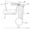
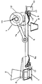
図1は本発明の散薬分配装置を備えた散薬分割包装装置の例を示す。この装置は、投入ホッパー2に散薬を入れて、フィーダ1を作動させると同時に、R分配皿5を1分間に60回転ほどの速度で回転させた状態で、トラフ3の先端部から散薬をR分配皿に供給している。
【0022】
フィーダ1は図2に示すように構成され、トラフ3下に固定された2枚の圧電素子4により、約100Hzの周波数で振動する。トラフ3下の支持板20には、圧電素子4の振動方向に平行して振動センサー21が取り付けられている。圧電素子4の下部は固定台座22に固定されていて、固定台座22はバネ23でフィーダ1の振動を吸収するようにして散薬分割包装装置本体に取り付けられる。
【0023】
図3はホッパー角度支持装置を示す。トラフ3の上方には投入ホッパー2がホッパー角度支持装置の支持部材24に支持されており、この支持部材24は支柱25を軸にして回動し支持部が昇降するようになっている。この支持部材24を回動させるアーム部材26は、モータ27により回転する図示しないクランク軸に接続されている。モータ27によりクランク軸が回転すると投入ホッパー2の開口角度を可変させることができる。
【0024】
モータ27はステッピングモータを採用しており、目的の開口角度に合わせた位置で投入ホッパー2を停止させて保持できる。また、散薬の供給が終了した際、投入ホッパー2表面に付着した散薬は、前記モータ27を細かい角度(約15の範囲)で制御して投入ホッパー2を振動させることにより、トラフ3に落とされる。また、ソレノイド部材により投入ホッパー2を打撃することで、投入ホッパー2に付着した散薬をトラフ3に落としてもよい。
【0025】
このフィーダ1の投入ホッパー2の投入口付近には、図4(a)(b)に示す集塵装置28を備えることが好ましい。
【0026】
この集塵装置28は投入ホッパー2の投入口の外周部より大きい筒状の枠で形成され、支持パイプ29に回転自在に支持されているため、図4(b)のように、集塵装置28が投入ホッパー2より離反するように設けられている。
【0027】
集塵装置28の筒状枠の内周には、集塵口30が設けられ、散薬を投入ホッパー2内に投入したときに発生する薬粉塵が集塵口30から集塵装置28に吸引されるようになっている。
【0028】
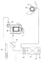
この集塵装置28は図5に示すようにクリーナ装置40に接続されている。クリーナ装置40は、フィルター41とファン42で構成され、切り替えバルブ43に接続されている。
【0029】
前記集塵装置28の集塵口30から吸い込まれた散薬粉塵は、支持パイプ29を通して切り替えバルブ43を経てクリーナ装置40に導かれる。途中流量調整装置44により、集塵装置28の集塵口30から吸い込む流量が調整される。
【0030】
この他、切り替えバルブ43に接続されているユニットに、R分配皿5の表面を清掃する回転ブラシ付きクリーナー45や、掃除機46が設けられているが説明を省略する。
【0031】
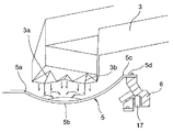
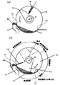
図1に示すR分配皿5は、プレス加工で形成され、R形状(断面円弧状)の窪み部を備えている。窪み部の内周側はドーナツ状に開口しており、その内周側縁5aのRの反り上がり角度は約23.5度に設定されている。
【0032】
一方、R形状の窪み部の最下点5bより外周側の外周側縁5cは、Rの反り上がり角度が約50度に設定され、内周側縁5aのRの反り上がり高さより外周側縁5cの反り上がり高さが高く設定されている。これは、フィーダ1から分配される散薬が、R分配皿5を前記条件の回転速度で回転させても散薬がR分配皿5の遠心力で飛散しないようにするためである。
【0033】
外周側縁5cの更に外周部には、R分配皿5を回転させるための支持リング6を保持する鍔5dがR分配皿5と一体に形成されている。
【0034】
図6は、フィーダ1の配置を示す図である。
【0035】
ここで示すトラフ3は、図7に示すように先端部が2段階に下がっており、トラフ3の先端部は更に2つの誘導溝3a,3bを備えている。
【0036】
この2つの誘導溝3a,3bは、それぞれR形状の窪み部最下点5bを挟んで内外周の位置に配置されている。これにより、トラフ3の先端部から落下する散薬は、誘導溝3a,3bから多く落下し、R分配皿5に誘導溝3a,3bからそれぞれ落下した散薬は、R形状の窪み部最下点5bの方向に跳ね、跳ねた散薬同士が当たってR形状の窪み部最下点5bの位置に堆積する。
【0037】
このため、散薬はR分配皿5から飛散する事が少ない。またトラフ3は、先端部が2段階に下がっていて落下高さが押さえられるので、散薬は跳ね難くなる。R分配皿5に堆積する散薬は、R形状の窪み部最下点5bの上方を頂点に高く積もり難く、左右に分散して堆積する。
【0038】
本発明のようにR分配皿5を高速回転させるためには、フィーダ1のトラフ3の落下口とR分配皿5をできるだけ接近させるか、R分配皿5の最下点を挟んだ内外径のそれぞれの傾斜面に散薬を落として、回転しているR分配皿5から飛び跳ねないようにする工夫が必要である。
【0039】
このようにして散薬がR分配皿5に分配されると、R分配皿5を一定の角度毎に送り込み、その1回に送り込まれた範囲の散薬が掻き出し装置7で包装ホッパー8に掻き落とされる。包装ホッパー8のシャッターを解放すると、散薬が包装紙10に投入され、シール装置11の回転により包装紙10が順次引き込まれて包装されるようになっている。
【0040】
前記掻き出し装置7は、分配中は上方に待避しており、分配が終了すると降下してR分配皿5に接触するようになっており、掻き出し装置7が1回転するとR分配皿5の内径方向に散薬を掻き落とすようになっている。
【0041】
これらの分配や分割動作が終了すると、図5に示す回転ブラシ付きクリーナー45を作動してR分配皿5のR形状の窪み部表面を清掃して次の処方を待機する。
【0042】
掻き出し装置7の動作は次のように行われる。
【0043】
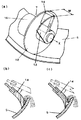
図8(a)に示すように掻き出し装置7は、デイスク12によりR分配皿5に堆積した散薬を切り出し、R分配皿5を回転させて送った範囲の散薬がディスク12に掻き寄せられた後に、掻き出し装置7の回転によりガイド板13がR分配皿5に堆積した散薬を仕切り、前記ディスク12とガイド板13の間にもうけた掻き板14によりR分配皿5から掻き落とすようになっており、これらの駆動はモータ15によって行われる。
【0044】
図8(b)や(c)に示すように掻き板14の先端部はR分配皿5の内面を接触しながら掻き出し装置7の回転にしたがって、R内面を移動する事になるが、図8(c)に示すように掻き板14の先端部に切り込みを入れると、R分配皿5から離反するときに、掻き板のゴム材の反発が押さえられ、顆粒状の散薬が飛び跳ねにくくなる。
【0045】
図9の(a)(b)は掻き出し装置の側面図である。
【0046】
掻き出し装置7のディスク12の回転は一定速度で回転するのではなく、所定の決まった範囲を設定された速度で回転する。
【0047】
図9の(b)に示すように、掻き出し中の動作は次のように範囲が分断されている。R分配皿5の内周側縁5aの位置で、掻き出し装置7は停止するか最低速度に減速されている。
【0048】
このR分配皿5の内周側縁5aの位置を通過して、しばらくは回転速度を加速し、一定の位置からはほぼ一定の速度で回転軸xが回転する。加速終了からR分配皿5の外周側縁5cの範囲を速度調整区間として設定している。
【0049】
この速度調整区間は、回転基準として掻き板14がR分配皿5の外周側縁5cに到達したことを基準としているのではなく、ガイド板13の先端部が到達しているかがポイントである。たとえばR分配皿5の分割送り角度が小さい場合、ガイド板13の先端部がR分配皿5の外周側縁5cの位置まで到達するより早く分割送り角度が次の停止点に到達する。
【0050】
このため回転軸x速度調整区間で減速する必要はないが、設定された包装数が少なくなると、それに対応してR分配皿5の分割送り角度が大きくなってくるため、回転軸x速度調整区間で一定速度で回転させると、分割送り角度が次の停止点に到達するより早くガイド板13の先端部がR分配皿5の外周側縁5cの位置まで到達してしまい、そのまま回転軸xを回転させると堆積する散薬にガイド板13が接触しながらもなお、R分配皿5が送り込まれ、分割に必要なR分配皿5に堆積する散薬範囲をディスク12とガイド板13の間に取り込むことができず、分包誤差が生じる。
【0051】
このため、包装数やR分配皿5の送り角度の増減に対応した時間データを記憶しておき、ガイド板13の先端部がR分配皿5の外周側縁5cの位置まで到達する時間が前記記憶される時間より早いことが予測される場合には、回転軸xの回転速度を速度調整区間で減速して回転するように制御している。
【0052】
図1に示すようにR分配皿5上方には、錠剤を手撒きして分割包装する錠剤分割機37が備えられており、包装ホッパー8に落下させるシャッター38を備えた錠剤シュート39が分割機の幅に対応して備えられている。
【0053】
錠剤分割機37は小さな枡目状に配置した容器であり、各枡の底面にもそれぞれ図示しない底板シャッターが設けられている。
【0054】
この底板シャッターは錠剤分割機37の移動方向に対して底に接触しながら移動するため、シュート39の開口部に達すると錠剤分割機37の底板シャッターが自然解放して、容器内の錠剤をシュート39に落とすようになっている。このシュート39の開口部は錠剤分割機37の移動方向に対して、錠剤分割機37の移送方向の1つの枡を幅方向に設けた枡の数で割ったピッチで、階段状のスリットを設けており、錠剤分割機37を前記錠剤分割機37の移送方向の1つの枡を幅方向に設けた枡の数で割ったピッチで移送しているため、手前の角から幅方向に順に錠剤分割機37の底板シャッターが解放する。
【0055】
シュート39の出口に設けたシャッター38はこれらの一連の動作に伴ったタイミングで作動するようになっている。
【0056】
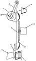
図14は従来の掻き出し装置7及びR分配皿5の駆動や包装ホッパー8等の配置を示す。掻き出し装置7のディスク12を昇降させる昇降アーム7aの回転軸や包装ホッパー8はR分配皿5の外側に設けられ、R分配皿5はR分配皿駆動モータ16で駆動され、フィーダ1は、R分配皿5の外側に配置され、投入ホッパー2に散薬を入れると、トラフ3を通じてR分配皿5のR部分に供給される。
【0057】
図10に示すR分配皿5の中心方向に散薬を掻き出して包装する装置の場合、前記図14に示すようにR分配皿5の回転駆動は中心部に持つ事ができないため、R分配皿5の外周部に支持リング6を設け、支持リング6をローラ17で回転支持している。
【0058】
R分配皿5の支持は、このような装置において重要な役割を果たしており、回転支持の手段に問題があると、R分配皿5の回転中に発生する振動により、分配中に散薬がR形状の窪み部最下点5bの同心円上からそれて蛇行や偏心して分配されたり、または、円周上の一部分に散薬が集中してくる現象が発生し、分割精度に直接影響する。
【0059】
この回転支持に関する問題を解決する技術として、R分配皿5の回転中心軸で支持することで容易に解決する事ができるが、本発明のようにR分配皿5の回転中心軸方向に散薬を掻き出す場合は、少なくともR分配皿5の内周側縁5aより外側でR分配皿5の回転支持を行う制約を受けることになり、R分配皿5の内周側縁5aより外側でR分配皿5の回転支持を行う場合、R形状の窪み部最下点5bと回転支持手段の関係からR分配皿5の回転軸の同心度を組み立て時に調整するのが困難となる上、支持リング6をR分配皿5の回転軸から外周方向に離反させればさせるほど、R分配皿5の回転軸の同心度を組み立て時に調整する難易度が高くなる関係がある。
【0060】
また、従来、R分配皿5を1分間に30回転で回転させる場合では、R分配皿5の回転支持部をある程度、回転軸から外周方向に離反させて支持する事も可能である。しかし、1分間に60回転で回転させる本発明の場合、R分配皿5をプレス加工する精度や形状が厳しく求めなければならず、支持構造についても周速度が早い位置をローラ17などで支持するなど条件があり、さらにはこのローラ17の配置を工夫しなければ飛散する散薬が支持リング6とローラ17間に噛み込み、従来では考えられなかった騒音を発生させる条件を含んでいる。(従来は、R分配皿5の支持構造では、散薬分配皿の落下位置より内側で回転速度が低速であり、ローラの配置にそれほど気にしなくても飛散する散薬が支持リングとローラ間に噛み込む問題も発生しない。)
【0061】
これらの事から、前記支持リング6とローラ17間に散薬が噛み込むと、R分配皿5を振動させるため、分配中に散薬がR形状の窪み部最下点5bの同心円上からそれて蛇行や偏心して分配されたり、または、円周上の一部分に散薬が集中してくる現象が発生する問題が生じる。本発明では、図7に示すように、支持リング6とローラ17との接触部をR分配皿5の鍔5dの位置より下方で、鍔5dの外周径の略内側径方向に、内周側縁5aより外側径の位置とすることで、分配中の散薬が飛散した時に、支持リング6とローラ17との接触部に噛み込む事はない。
【0062】
また、支持リング6のローラ17との接触部をR分配皿5の鍔5dの位置より下方で、鍔5dの外周径の略外側径方向の位置とする場合、R分配皿5から遠心力などの条件で、飛散する散薬の飛来放物範囲の内側に設ける場合、極まれに支持リング6とローラ17との接触部に散薬が噛み込む事があるがそれほどの問題とはならず、このような場合でも、支持リング6のローラ17との接触部を図6に示すようなブラシ等で挟まって支持リング6に張りついている散薬を除去すれば連続的な振動を発生させることはできる。
【0063】
しかし、支持リング6のローラ17との接触部をR分配皿5の鍔5dの位置より同じか上方で、鍔5dの外周径の略外側径方向の位置とする場合や、R分配皿5から遠心力などの条件で、飛散する散薬の飛来放物範囲の外側に設ける場合は、支持リング6とローラ17との接触部に散薬が噛み込む事が頻繁に発生するようになるため、たとえ、支持リング6とローラ17との接触部を図6に示すようなブラシ部材36等で挟まって支持リング6に張りついている散薬を除去しても、短時間に除去できないで張り付く散薬が溜まり、連続的な振動が発生するようになるため好ましくない。
【0064】
図11の(a)(b)(c)は支持リング6とローラ17の支持形態を示す図である。
【0065】
図11の(a)の支持リング6とローラ17の支持形態は、支持リング6の内径側を外周方向の下方に向かって押しつけるローラ17と、支持リング6が搭載されるローラ17とにより、2方向から支持するようになっており、R分配皿5の裏面側に支持リング6とローラ17が配置されている。
【0066】
図11の(b)の支持リング6とローラ17の支持形態は、支持リング6の外径側を内周方向の下方に向かって押しつけるローラ17と、支持リング6が搭載されるローラ17とにより、2方向から支持するようになっており、R分配皿5の外周部に備えた鍔5dの更に外側から上方に向かって支持リングから延びる支持リングガイド6aを備えている。
【0067】
このため、R分配皿5の表面から飛散する散薬は、前記支持リングガイド6aによりR分配皿5の外周側に飛散する事が極力少なくなり、偶然にも支持リング6とローラ17の間に散薬が挟まることはほとんど発生しない。
【0068】
ここで、支持リングガイド6aの形状は上方に向かって延びる支持リングとしたが、ローラ17の上方に被さるように外周方向へ延びる支持リングガイド6aとしてもよく、支持リングガイド6aの代わりに、R分配皿5の外周部に備えた鍔5dによって、ローラ17の上方に被さるようにしてもよい。
【0069】
図11の(c)の支持リング6とローラ17の支持形態は、支持リング6の外径側を内周方向の下方に向かって押しつけるローラ17と、支持リング6が搭載されるローラ17とにより、2方向から支持するようになっており、R分配皿5の外周部に備えた鍔5dの裏面に、鍔5dと支持リング6の間に間隙を設け、この間隙を起点としてローラ17の上方に被さるように設けられたカバー部材18によって、ローラ17が支持リング6に接触しない周囲を覆っている。
【0070】
このように、カバー部材18によってローラ17が覆われているため、偶然にも支持リング6とローラ17の間に散薬が挟まることはほとんど発生しない。
【0071】
また、ローラ17の当たり面は、樹脂などの材料により、振動を吸収できる柔らかい材質を前記支持リングに固着しても良く、逆に、ローラ17の表面材質を樹脂、またはゴム係の材質を用いることで、R分配皿5の高速化に対応する事が可能となる。
【0072】
更に、ローラ17は、可能な限り、直径の大きいものを採用すれば、ローラ17の回転速度が下がり、耐久性や騒音、振動を押さえることが可能になる。
【0073】
なお、ここで開示した図11の(a)(b)(c)は実施に当たり示した手段であって、散薬分配皿の回転支持リングと前記回転支持リングに接触するローラの接触部分に、R分配皿の遠心力により飛散した顆粒等の散薬が噛み込まない位置に配置したとは、カバーで覆う等のあらゆる手段が発明の趣旨に含まれている。
【0074】
図12は、R分配皿5の取り付けについての形態が違う形式を示すものである。
【0075】
ここで上げるR分配皿5の鍔5dには、支持リング6と締め付けるネジ穴を持たない形態であり、R分配皿5の鍔5dは水平ラインより下方向に環状に折り曲げられている。
【0076】
このように鍔5dを下方に曲げることにより、曲げ角度が水平方向から垂直方向に曲げ角度がきつくなるに従い、R分配皿5の曲げ強度が向上するが、反面支持リング6に取り付ける構造に難点が生じる。
【0077】
しかし、図12のように支持リング6と鍔5dを接触させ、締め付けネジ19を皿ネジまたは支持リング6と鍔5dの勾配傾斜を備えた止め具を締め付けネジ19で締め付ける事でその問題を解決している。
【0078】
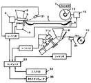
図13は、本発明が使用される包装装置の制御ブロック図である。
【0079】
なお、各ユニットにおける符号については、前記説明と共通の符号を使用してここでの詳細な説明は省略する。
【0080】
この包装装置では、キーボードなどの入力手段32により、分割数や動作条件などが入力される。分割数は、処方箋情報を基に計量調合を完了した薬剤を投入ホッパー2に投入した後、日の服用回数と処方された日数から設定される。動作条件とは、主にフィーダの供給量を薬剤の種類が変わる毎に調整する事や包装形態等の設定を行う事である。
【0081】
ここで入力された情報は、コンピュータ33に送り、それぞれの情報別に対応するシーケンサーに伝送される。コンピュータ33はマイコンからパソコン間での概念を含む物とする。
【0082】
包装スタートの開始をもって、投入ホッパー2に投入された散薬は、入力手段32により設定した条件で圧電素子4が動作して散薬をトラフ3からR分配皿5に供給すると同時に、R分配皿5を1分間に60回転の早さでモータ16を回転させる。
【0083】
トラフ3の先端部には散薬の供給を監視するセンサー31を備え、散薬の供給が終了したことを、検出の無しで判断し、次工程の投入ホッパー2内に付着した散薬のクリーニング、及び圧電素子4をフル稼働させてトラフ3の残薬を供給する。
【0084】
動作終了後、R分配皿5の回転を停止させて、掻き出し装置7のデイスク12をR分配皿5上に降下させる。
【0085】
分割範囲の角度分R分配皿5を送り込み、続いて掻き出し装置7の駆動はモータ15を回転させ、掻き出し装置7の掻き板14が内周側縁5a離脱するのを受けて、次の分割範囲の角度分R分配皿5を送り込み、設定された包装数の数だけ動作を繰り返す。
【0086】
この分割動作と対応して、ヒータローラ11a,11bが動作するようになっており、11aは袋を幅方向に一定間隔で区切るようにシールし、11bは長手方向に筒状にシールする。
【0087】
散薬は、包装紙を2つ折りにして広げた位置に設けた包装ホッパー8を介して包装され、この包装紙の表面には印字装置34によって必要な患者名や服用時期などが印字される。
【0088】
また、ホストコンピュータ35から必要な情報を受信して動作させることも可能である。
【発明の効果】
以上のように本発明によれば、断面円弧状の窪み部を備えたドーナツ状の散薬分配皿を所定のピッチ角度で回転することにより、前記窪み部に堆積した散薬を掻出装置により1包分ずつ掻き出し可能とする散薬分配装置において、前記散薬分配皿の外周側縁が内周側縁よりも高く形成されている構成とした。また、前記散薬分配皿の外周側縁には鍔部が設けられており、前記散薬分配皿は、前記鍔部を介して回転可能に支持されている構成とした。
【0089】
このことにより、散薬分配皿を高速回転さられる分配皿をプレス加工で高精度を維持して低価格で製造する事ができる。
【0090】
また、R形状の窪み部外径縁の外側に備えた鍔部と、散薬分配皿の回転軸と同心軸に回転支持リングを前記鍔部に沿って設けられ、回転支持リングに前記鍔部を固定すると共に、前記散薬分配皿の回転支持リングを回転可能に支持する構成とした。
【0091】
このことにより、実際に、散薬分配皿を回転させた場合に、散薬分配皿のR形状の窪み部径の軸と、散薬分配皿を回転させた時の回転軸の精度や散薬分配皿の回転軸の振れ、または、散薬分配皿を高速回転させた時の騒音や振動の軽減等の要求される精度に対して、容易に組立や調整が可能にする等の課題を解決する事ができる。
さらに、散薬分配皿に散薬を供給するトラフの先端部に誘導溝を備え、トラフを振動させながら誘導溝から散薬を散薬分配皿に供給するようにしたので、散薬が散薬分配皿から飛散することがない。
誘導溝は散薬分配皿の窪み部の最下点を挟んで内周側と外周側に配置されているので、誘導溝から落下した散薬は窪み部最下点の方向に跳ね、跳ねた散薬同士が当たり窪み部最下点の位置に堆積する結果、散薬が散薬分配皿から飛散することがない。
トラフの先端部を2段階に下げて散薬分配皿への散薬の落下高さを押さえたので、散分配皿上で薬剤が跳ね難くなり、散薬を分散して堆積させることができる。
【図面の簡単な説明】
【図1】本発明を示す分割包装装置の斜視図。
【図2】本発明に使用するフィーダ側面図。
【図3】本発明に使用する投入ホッパーの開閉装置側面図。
【図4】本発明の投入ホッパー集塵装置の正面図と側面図。
【図5】本発明の集塵装置の経路図。
【図6】本発明に使用するフィーダの配置を示す図。
【図7】本発明のトラフから落下する散薬の落とし方について示す図。
【図8】本発明に使用する掻き出し装置を示す図。
【図9】本発明に使用する掻き出し装置を示す図。
【図10】本発明を示す分割包装装置の側面図。
【図11】本発明を示すR分配皿の支持断面図。
【図12】本発明のR分配皿の支持手段を示す断面図。
【図13】本発明を示す分割包装装置のブロック図。
【図14】従来例を示す分割包装装置の側面図。
【符号の説明】
3. トラフ
3a.誘導溝
3b.誘導溝
5. R分配皿
5a.内周側縁
5b.R形状の窪み部最下点
5c.外周側縁
5d.鍔
6. 支持リング
6a.支持リングガイド
17.ローラ
18.カバー部材
19.締め付けネジ
36.ブラシ部材[0001]
BACKGROUND OF THE INVENTION
Since the present invention wraps the prescribed powder in a single dose,On the distribution trayAfter dispensing, scrape with a scraping deviceDivideRuPowder distribution deviceAbout.
[0002]
[Prior art]
Conventional powder dispensing deviceThenThe scraping direction of the scraping device is distributeddishPowder that has been scraped to the outer circumference with respect to the rotation axis, and scraped with a scraping deviceTheCan be put into packaging hopperlike,R-shaped depression on distribution trayofIn order to keep the outer diameter edge low,Outside diameterThe rake angle was formed around 23 degrees, and the disk diameter of the scraping device was 110 mm.
[0003]
For this reason, powder must be deposited on this distribution dish.MinutesIf the diameter of the tray is 500mm and it is not rotated by pressing around 30 rotations per minute, powder such as granules will be distributedFrom the depression of the distribution trayThe problem of scattering by centrifugal force arises.
[0004]
Powder splitting packaging equipment requires powder splitting accuracy.,As one means for improving the division accuracy, it is desirable to rotate the distribution tray as fast as possible and supply it from the powder feeder to the distribution tray. As such a technique, Japanese Patent Laid-Open No. 57-86401 is disclosed. ing.
[0005]
In the technique disclosed in Japanese Patent Laid-Open No. 57-86401, powder is deposited from a powder feeder onto a V-shaped annular bowl, and then the V-shaped tip of the V-shaped annular bowl is opened and deposited on the R distribution tray. Drop the powder, scrape the powder deposited on the R distribution tray with a scraping device, drop it on the packaging hopper and pack it.Yes.When depositing powder from a powder feeder onto a V-shaped annular bowl, the powder will not be scattered by centrifugal force even if it is rotated around 60 rotations per minute because of the V-shaped annular bowl. In the process of powder passing through the two steps of scraping process, fine powder powderButSurfaces such as powder feeder and R distribution trayRemaining inIn other words, when the prescribed powder is packaged, there is a disadvantage that it is reduced.
[0006]
In order to overcome this drawback, the applicant has disclosed Japanese Patent Application Laid-Open No. 8-85502.
[0007]
JP-A-8-85502IsAn annular R-shaped depression is provided on the outer periphery of the powder distribution dish, and the distribution dish in which the inner diameter portion of the R-shaped depression is formed in a donut shape is rotated at high speed to deposit powder in the R-shaped depression. The distribution of the powder is distributed by supplying the powder by rotating the distribution tray by a certain angle with the scraping direction of the scraping device that scrapes the powder deposited in the R-shaped depression as the rotation center direction of the powder distribution tray extracted in the donut shape. Supply equipmentWhereIt is disclosed.
[0008]
Further, with the downsizing of the machine, conventionally, the scraping mechanism and the packaging hopper are installed on the outer peripheral portion of the
[0009]
[Problems to be solved by the invention]
By the way, in order to manufacture a powder distribution tray as disclosed in Japanese Patent Laid-Open No. 8-85502 at a low price, it is desirable to press the powder distribution tray, and since it comes into contact with the powder, durability and cleanliness are maintained. Also in the above, what uses stainless steel is desirable.
[0010]
In addition, the powder distribution tray requires a high degree of accuracy. In particular, the R-shaped hollow diameter of the powder distribution plate, the accuracy of the rotation axis when the powder distribution plate is rotated, and the rotation axis of the powder distribution plate Shaking, noise and low vibration, deflection and twisting of the powder distribution tray are required.
[0011]
In addition, when the R distribution tray is rotated at a high speed, a part of the powder scattered during distribution from the feeder is blown away by the rotational centrifugal force.Granules etc.Contact portion of the roller where powdered powder contacts the rotating support ring and the rotating support ringBiteLook intoresult,Sudden noise generation and rattling of the R distribution tray, ResistantIt is required that these problems do not occur because of the decline in durability.
[0012]
Furthermore, the problem of machine downsizing is one of the problems.
[0013]
In the present invention, the powder distribution tray is cheap and the powder distribution tray can be pressed to maintain high accuracy.UnaKeeping the shape, and rotating the powder distribution tray, when the powder distribution tray is actually rotated, the R-shaped recess diameter axis of the powder distribution tray, the accuracy of the rotation axis when rotating the powder distribution tray, and the rotation of the powder distribution tray It can be easily assembled and adjusted for the required accuracy such as noise and vibration reduction when rotating the shaft or rotating the powder distribution tray at high speed, and it will scatter during distribution from the feeder. A part of the powder is blown off by the rotational centrifugal force and is engaged in the rotation support ring and the contact portion of the roller that is in contact with the rotation support ring.
[0014]
[Means for Solving the Problems]
In order to solve the above problems, the present invention provides:In a powder distribution device that allows a powdered powder accumulated in the hollow portion to be scraped by a scraping device one by one by rotating a donut-shaped powder distribution tray having a hollow portion having an arcuate cross section at a predetermined pitch angle. The outer periphery side edge of the powder distribution tray is formed higher than the inner periphery side edge.The configuration.
Moreover, the collar part was provided in the outer peripheral side edge of the said powder distribution tray, and it was set as the structure by which the said powder distribution tray was rotatably supported through the said collar part.
[0015]
Thereby, the distribution tray which can rotate the powder distribution tray at high speed can be manufactured at a low price while maintaining high accuracy by press working.
[0016]
Also, the flange provided outside the outer peripheral side edge of the R-shaped depression and the lowest point of the R-shaped depression of the powder distribution tray are concentric with the rotation axis supported by the rotation support ring. The rotary support ring of the powder distribution tray is rotatably supported along the collar.
[0017]
By this, when the powder distribution dish is actually rotated, the accuracy of the R-shaped hollow portion diameter of the powder distribution dish and the rotation axis when the powder distribution dish is rotated and the rotation of the powder distribution dish It is possible to solve problems such as easy assembly and adjustment with respect to required accuracy such as reduction of noise and vibration when rotating the shaft or the powder distribution tray at high speed.
[0018]
Furthermore,The contact portion between the support ring and the roller is provided at a position where powdered powder scattered during rotation of the powdered distribution tray cannot be caught..
[0019]
As a result, while distributing the powder from the feeder, even if the
[0020]
DETAILED DESCRIPTION OF THE INVENTION
Examples of the present invention will be described below.
[0021]
FIG. 1 illustrates the present invention.With powder distribution deviceAn example of a powder split packaging deviceThe This deviceAt the same time as putting powder into the
[0022]
feeder1Is configured as shown in FIG.,Vibration at a frequency of about 100 Hz by two
[0023]
Figure 3 shows the hopper angle support deviceTheAbove the
[0024]
The
[0025]
It is preferable that a
[0026]
This
[0027]
A
[0028]
This dust collector28 is FIG.As shown inIt is connected to the cleaner device 40.The
[0029]
Powdered dust sucked from the
[0030]
In addition, the unit connected to the switching
[0031]
The
[0032]
On the other hand, the concave portion of the R shapeofBottom point 5bMore outer sideThe
[0033]
OutsideOn the outer periphery of the
[0034]
Figure 6 shows the feeder1It is a figure which shows arrangement | positioning.
[0035]
The trough shown here3As shown in FIG. 7, the tip portion is lowered in two stages, and the tip portion of the
[0036]
These two
[0037]
For this reason, the powder is less likely to scatter from the R distribution tray 5.Yes.Also trough3The tip is lowered in two stagesAndDrop height is suppressedSo powder isHard to jumpBecome.Accumulate on R distribution tray 5Powder, R-shaped hollow portion lowest point 5bUpwardTo the apex highPileIt is difficult to measure and deposits are distributed from side to side.
[0038]
R distribution dish as in the present invention5In order to rotate the feeder at high speed,1TroughThreeDrop port and R distribution tray5Or as close as possible to the R distribution tray5ofMostRotating R-distribution dish with powder spray dropped on each inclined surface with inner and outer diameters across the lower point5It is necessary to devise so that it will not jump off.
[0039]
In this wayPowder in R distribution tray 5Be distributedAnd
[0040]
The
[0041]
When these dispensing and dividing operations are completed, the cleaner 45 with a rotating brush shown in FIG.TheActuate to clean the surface of the R-shaped depression of the
[0042]
The operation of the
[0043]
[0044]
As shown in FIGS. 8B and 8C, the tip of the scraping
[0045]
FIGS. 9A and 9B are side views of the scraping device.
[0046]
Scraping device7Disc12The rotation does not rotate at a constant speed, but rotates at a set speed within a predetermined range.
[0047]
As shown in Fig. 9 (b), the range during the scraping operation is divided as follows:Yes.At the position of the inner
[0048]
After passing through the position of the inner
[0049]
In this speed adjustment section, the
[0050]
For this reason, it is not necessary to decelerate in the rotation axis x speed adjustment section. However, if the set number of packages decreases, the divided feed angle of the
[0051]
For this reason, time data corresponding to increase / decrease of the number of packages and the feed angle of the
[0052]
As shown in FIG. 1, above the
[0053]
Tablet splitting machine37Is a container arranged in a small grid, and a bottom plate shutter (not shown) is also provided on the bottom of each bowl.
[0054]
This bottom plate shutter is a tablet divider37Because it moves while touching the bottom with respect to the direction of movement, the chute39Tablet opening machine when reaching the opening of37The bottom plate shutter releases naturally and shoots the tablets in the container39It has come to drop. This shoot39The opening of the tablet divider37Tablet splitting machine37The tablet dividing machine is provided with a step-like slit at a pitch obtained by dividing one wrinkle in the transfer direction by the number of wrinkles provided in the width direction.37The tablet dividing machine37The tablet dividing machine in order from the front corner to the width direction is transported at a pitch divided by the number of wrinkles provided in the width direction.37The bottom plate shutter is released.
[0055]
shoot39Shutter at the exit38Operates at the timing associated with a series of these operations.
[0056]
Figure 14 shows a conventional scrapingDevice 7And R distribution tray5Driving and packaging hopper8Shows the arrangement of etc.TheScraping device7Lifting arm to raise and lower the disk 127aThe rotary shaft and the
[0057]
In the case of the device for scraping and packaging the powder in the center direction of the
[0058]
The support of the
[0059]
About this rotation supportproblemAs a technology to solve the problem5It can be easily solved by supporting it with the rotation center axis of the R distribution tray as in the present invention.5When scraping out powder in the direction of the rotation center axis, at least the R distribution dish5R distribution tray outside the inner peripheral edge 5a5Will be subject to the restrictions to support the rotation of the R distribution tray5R distribution tray outside the inner peripheral edge 5a5When the rotation support is performed, the R-distribution dish is obtained from the relationship between the R-shaped depression
[0060]
Conventionally, R distribution tray5In the case of rotating at 30 revolutions per minute5It is also possible to support the rotation support part of the rotation part away from the rotation axis to a certain extent in the outer circumferential direction.. But,In the case of the present invention rotating at 60 revolutions per minute, the R distribution tray5The accuracy and shape of pressing must be rigorously required, and the support structure must be positioned at a high peripheral speed.rollerThere are conditions such as supporting with 17, etc.rollerIf the arrangement of 17 is not devised, the scattered powder is scattered with the support ring 6roller17 includes a condition that bites between 17 and generates noise that could not be considered in the past. (Conventionally, R distribution tray5SupportIn structure, The rotation speed is lower than the falling position of the powder distribution tray,rollerEven if you don't care much about the arrangement of the powder,rollerThe problem of biting in between does not occur. )
[0061]
From these, the
[0062]
Also, the support ring 6rollerWhen the contact portion with 17 is positioned below the position of the
[0063]
However, the support ring 6roller17 is the same or above the position of the
[0064]
(A), (b), and (c) of FIG.rollerIt is a figure which shows the support form of 17.
[0065]
The
[0066]
The
[0067]
For this reason, the powder scattered from the surface of the
[0068]
Here, the shape of the
[0069]
The
[0070]
thislikeBy the cover member 18roller17 is covered, so it happens that the
[0071]
Also,Roller 17The contact surface may be made of a material such as resin, and a soft material that can absorb vibrations may be fixed to the support ring.rollerBy using a resin or rubber-related material for the
[0072]
Furthermore,roller17 can be as large as possible,Roller 17The rotation speed of the machine is reduced, and durability, noise, and vibration can be suppressed.
[0073]
It is disclosed hereFIG.(A), (b), and (c) are the means shown in the implementation, and were scattered by the centrifugal force of the R-distribution dish on the rotation support ring of the powder distribution dish and the contact part of the roller that contacts the rotation support ring. All means such as covering with a cover is included in the gist of the invention.
[0074]
FIG. 12 shows a form in which the form for attaching the
[0075]
The
[0076]
By bending the
[0077]
However, as shown in
[0078]
FIG. 13 is a control block diagram of a packaging apparatus in which the present invention is used.
[0079]
In addition, about the code | symbol in each unit, the detailed description here is abbreviate | omitted using the code | symbol common with the said description.
[0080]
thisPackaging equipmentsoThe number of divisions and operating conditions are input by the input means 32 such as a keyboard.TheThe number of divisions is,Based on prescription informationIn totalCompleted the amount formulationDrugIs set from the number of times a day is taken and the number of days prescribed.TheThe operating condition is mainly to adjust the supply amount of the feeder every time the type of medicine is changed and to set the packaging form.
[0081]
The information input here is sent to the
[0082]
At the same time as the start of packaging, the powder charged into the
[0083]
A
[0084]
After the operation is completed, the rotation of the
[0085]
The
[0086]
Corresponding to this division operation, the
[0087]
The powdered medicine is packaged via a
[0088]
It is also possible to operate by receiving necessary information from the
【The invention's effect】
As described above, according to the present invention,In a powder distribution device that allows a powdered powder accumulated in the hollow portion to be scraped by a scraping device one by one by rotating a donut-shaped powder distribution tray having a hollow portion having an arcuate cross section at a predetermined pitch angle. The outer periphery side edge of the powder distribution tray is formed higher than the inner periphery side edge.The configuration.Moreover, the collar part was provided in the outer peripheral side edge of the said powder distribution tray, and it was set as the structure by which the said powder distribution tray was rotatably supported through the said collar part.
[0089]
Thereby, the distribution tray which can rotate the powder distribution tray at high speed can be manufactured at a low price while maintaining high accuracy by press working.
[0090]
In addition, a flange provided outside the outer diameter edge of the R-shaped depression, a rotation support ring is provided along the flange on the concentric axis with the rotation axis of the powder distribution tray, and the rotation support ring includes the flange While being fixed, it was set as the structure which supports the rotation support ring of the said powder distribution tray rotatably.
[0091]
By this, when the powder distribution dish is actually rotated, the accuracy of the R-shaped hollow portion diameter of the powder distribution dish and the rotation axis when the powder distribution dish is rotated and the rotation of the powder distribution dish It is possible to solve problems such as easy assembly and adjustment with respect to required accuracy such as reduction of noise and vibration when rotating the shaft or the powder distribution tray at high speed.
In addition, a guide groove is provided at the tip of the trough that supplies powder to the powder distribution tray, and the powder is scattered from the powder distribution tray because the powder is supplied from the guide groove while vibrating the trough. There is no.
Since the guide groove is arranged on the inner and outer peripheral sides with the lowest point of the depression part of the powder distribution tray, the powder falling from the guide groove jumps in the direction of the lowest point of the depression part, As a result, the powder is not scattered from the powder distribution tray.
Since the tip of the trough is lowered in two stages and the drop height of the powder onto the powder distribution tray is suppressed, the drug becomes difficult to jump on the powder distribution tray, and the powder can be dispersed and deposited.
[Brief description of the drawings]
FIG. 1 is a perspective view of a split packaging apparatus showing the present invention.
FIG. 2 is a side view of a feeder used in the present invention.
FIG. 3 is a side view of a closing hopper opening / closing device used in the present invention.
FIGS. 4A and 4B are a front view and a side view of a charging hopper dust collector according to the present invention. FIGS.
FIG. 5 is a route diagram of the dust collector of the present invention.
FIG. 6 is a diagram showing an arrangement of feeders used in the present invention.
FIG. 7 is a view showing how to drop the powder falling from the trough of the present invention.
FIG. 8 is a view showing a scraping device used in the present invention.
FIG. 9 is a view showing a scraping device used in the present invention.
FIG. 10 is a side view of the split wrapping apparatus showing the present invention.
FIG. 11 is a support cross-sectional view of an R distribution tray showing the present invention.
FIG. 12 is a cross-sectional view showing a support means for the R distribution tray of the present invention.
FIG. 13 is a block diagram of a division packaging apparatus showing the present invention.
FIG. 14 is a side view of a split packaging apparatus showing a conventional example.
[Explanation of symbols]
3. trough
3a. Guide groove
3b. Guide groove
5. R distribution tray
5a. Inner edge
5b. Bottom point of R-shaped depression
5c. Outer edge
5d.鍔
6). Support ring
6a. Support ring guide
17.roller
18. Cover member
19. Tightening screw
36. Brush member
Claims (6)
前記散薬分配皿の外周側縁が内周側縁よりも高く形成されており、前記散薬分配皿の外周側縁には鍔部が設けられており、前記鍔部には支持リングが固定されており、前記支持リングには当該支持リングの内周面を押し付けるローラと当該支持リングが搭載されるローラとが接触しており、前記散薬分配皿は、前記ローラを介して回転可能に支持されていることを特徴とする散薬分配装置。In a powder dispensing apparatus that allows a powdered powder accumulated in the hollowed portion to be scraped by a scraping device one by one by rotating a donut-shaped powdered powder distribution tray having a hollowed portion having an arcuate cross section at a predetermined pitch angle. ,
An outer peripheral side edge of the powder distribution tray is formed higher than an inner peripheral side edge, and a collar portion is provided on the outer peripheral side edge of the powder distribution tray, and a support ring is fixed to the collar portion. A roller that presses the inner peripheral surface of the support ring and a roller on which the support ring is mounted are in contact with the support ring, and the powder distribution tray is rotatably supported via the roller. powdered medicine dispensing device, characterized in that there.
Priority Applications (2)
| Application Number | Priority Date | Filing Date | Title |
|---|---|---|---|
| JP25622498A JP4057159B2 (en) | 1998-09-10 | 1998-09-10 | Powder distribution device |
| KR1019990038617A KR100623387B1 (en) | 1998-09-10 | 1999-09-10 | Dispensing apparatus for powder medicine |
Applications Claiming Priority (1)
| Application Number | Priority Date | Filing Date | Title |
|---|---|---|---|
| JP25622498A JP4057159B2 (en) | 1998-09-10 | 1998-09-10 | Powder distribution device |
Related Child Applications (1)
| Application Number | Title | Priority Date | Filing Date |
|---|---|---|---|
| JP2007238925A Division JP4837641B2 (en) | 2007-09-14 | 2007-09-14 | Powder distribution device |
Publications (3)
| Publication Number | Publication Date |
|---|---|
| JP2000085703A JP2000085703A (en) | 2000-03-28 |
| JP2000085703A5 JP2000085703A5 (en) | 2005-11-17 |
| JP4057159B2 true JP4057159B2 (en) | 2008-03-05 |
Family
ID=17289668
Family Applications (1)
| Application Number | Title | Priority Date | Filing Date |
|---|---|---|---|
| JP25622498A Expired - Fee Related JP4057159B2 (en) | 1998-09-10 | 1998-09-10 | Powder distribution device |
Country Status (2)
| Country | Link |
|---|---|
| JP (1) | JP4057159B2 (en) |
| KR (1) | KR100623387B1 (en) |
Families Citing this family (13)
| Publication number | Priority date | Publication date | Assignee | Title |
|---|---|---|---|---|
| JP5407507B2 (en) * | 2009-04-10 | 2014-02-05 | 株式会社湯山製作所 | Powder scraping device |
| WO2014046148A1 (en) | 2012-09-19 | 2014-03-27 | 株式会社湯山製作所 | Drug feeder and drug dispensing device |
| CN102991736A (en) * | 2012-12-12 | 2013-03-27 | 无锡兰桂联芳医疗科技有限公司 | Tablet queuing adjustment mechanism of tablet counting machine |
| TWI673207B (en) * | 2013-07-12 | 2019-10-01 | 日商湯山製作所有限公司 | Drug dispenser and medicament dispensing device |
| WO2015076267A1 (en) * | 2013-11-22 | 2015-05-28 | 株式会社湯山製作所 | Drug dispensing device |
| WO2015076266A1 (en) * | 2013-11-22 | 2015-05-28 | 株式会社湯山製作所 | Medicine dispensing device |
| WO2015083641A1 (en) * | 2013-12-02 | 2015-06-11 | 株式会社湯山製作所 | Medicine dispensing system and medicine dispensing method |
| JP6601686B2 (en) | 2014-03-18 | 2019-11-06 | 株式会社湯山製作所 | Drug dispensing device |
| KR101701879B1 (en) | 2015-01-27 | 2017-02-02 | 류재경 | Apparatus for preparing powdered medicine |
| CN106742375A (en) * | 2016-12-30 | 2017-05-31 | 楚天智能机器人(长沙)有限公司 | For the detection method and device of box packing machine medicine plate induction system |
| CN107719718A (en) * | 2017-11-14 | 2018-02-23 | 信远德怡医疗科技(北京)有限公司 | A kind of automatic divided dose device of pulvis |
| CN108981327A (en) * | 2018-08-22 | 2018-12-11 | 内蒙古普康药业有限公司 | A kind of medicinal material machine for stir-frying Chinese medicine |
| KR20240004218A (en) | 2021-04-27 | 2024-01-11 | 가부시키가이샤 유야마 세이사쿠쇼 | Medicine feeder and medicine dispensing device |
Family Cites Families (1)
| Publication number | Priority date | Publication date | Assignee | Title |
|---|---|---|---|---|
| JP3344840B2 (en) * | 1994-09-19 | 2002-11-18 | 正二 湯山 | Drug volume divider |
-
1998
- 1998-09-10 JP JP25622498A patent/JP4057159B2/en not_active Expired - Fee Related
-
1999
- 1999-09-10 KR KR1019990038617A patent/KR100623387B1/en not_active IP Right Cessation
Also Published As
| Publication number | Publication date |
|---|---|
| KR20000023064A (en) | 2000-04-25 |
| KR100623387B1 (en) | 2006-09-12 |
| JP2000085703A (en) | 2000-03-28 |
Similar Documents
| Publication | Publication Date | Title |
|---|---|---|
| JP4057159B2 (en) | Powder distribution device | |
| JP5252072B2 (en) | Tablet feeder powder removal device | |
| US20230192340A1 (en) | Rotary Filling Machine | |
| KR101860578B1 (en) | Powder removal device of medicine dispenser | |
| JP4787338B2 (en) | Medicine packaging machine | |
| JP4837641B2 (en) | Powder distribution device | |
| JPH0218227A (en) | Fixed-quantity feeder for bulk material | |
| JP2000085701A (en) | Powdered medicine feeder | |
| US8444013B2 (en) | Food topping device including a vibration device and adjustable discharge pan and screen assembly | |
| JP2563196Y2 (en) | Powdered dose metering device | |
| JP2000085719A (en) | Powdered medicine feeder | |
| GB2159504A (en) | Parts feeder | |
| JPH0624930Y2 (en) | Coin sending device | |
| KR200307228Y1 (en) | Pill sorting apparatus | |
| EP0288177A2 (en) | Parts supply hopper | |
| KR100613020B1 (en) | Feeder for powder medicine | |
| TWI294391B (en) | Powder scraping apparatus | |
| US4716280A (en) | Particle counting device | |
| JP2005200090A (en) | Tea leaf delivering mechanism in tea metering machine | |
| JP2010184743A (en) | Powdered medicine dispensing device and dividing and packaging machine | |
| JP2004258951A (en) | Coin delivery device | |
| JPH0648507B2 (en) | Bowl for coin dispenser | |
| JPS6221684B2 (en) | ||
| JP2001045902A (en) | Feeding machine for livestock | |
| JPH053101U (en) | Powder quantitative feeder |
Legal Events
| Date | Code | Title | Description |
|---|---|---|---|
| A521 | Written amendment |
Free format text: JAPANESE INTERMEDIATE CODE: A821 Effective date: 20050823 Free format text: JAPANESE INTERMEDIATE CODE: A523 Effective date: 20050823 |
|
| A621 | Written request for application examination |
Free format text: JAPANESE INTERMEDIATE CODE: A621 Effective date: 20050823 |
|
| RD02 | Notification of acceptance of power of attorney |
Free format text: JAPANESE INTERMEDIATE CODE: A7422 Effective date: 20050823 |
|
| A521 | Written amendment |
Free format text: JAPANESE INTERMEDIATE CODE: A523 Effective date: 20050829 |
|
| A521 | Written amendment |
Free format text: JAPANESE INTERMEDIATE CODE: A523 Effective date: 20050929 |
|
| A977 | Report on retrieval |
Free format text: JAPANESE INTERMEDIATE CODE: A971007 Effective date: 20070711 |
|
| A131 | Notification of reasons for refusal |
Free format text: JAPANESE INTERMEDIATE CODE: A131 Effective date: 20070717 |
|
| A521 | Written amendment |
Free format text: JAPANESE INTERMEDIATE CODE: A523 Effective date: 20070914 |
|
| TRDD | Decision of grant or rejection written | ||
| A01 | Written decision to grant a patent or to grant a registration (utility model) |
Free format text: JAPANESE INTERMEDIATE CODE: A01 Effective date: 20071113 |
|
| A61 | First payment of annual fees (during grant procedure) |
Free format text: JAPANESE INTERMEDIATE CODE: A61 Effective date: 20071213 |
|
| R150 | Certificate of patent or registration of utility model |
Free format text: JAPANESE INTERMEDIATE CODE: R150 |
|
| FPAY | Renewal fee payment (event date is renewal date of database) |
Free format text: PAYMENT UNTIL: 20101221 Year of fee payment: 3 |
|
| LAPS | Cancellation because of no payment of annual fees |