JP4054690B2 - Printing control apparatus and method - Google Patents
Printing control apparatus and method Download PDFInfo
- Publication number
- JP4054690B2 JP4054690B2 JP2003035319A JP2003035319A JP4054690B2 JP 4054690 B2 JP4054690 B2 JP 4054690B2 JP 2003035319 A JP2003035319 A JP 2003035319A JP 2003035319 A JP2003035319 A JP 2003035319A JP 4054690 B2 JP4054690 B2 JP 4054690B2
- Authority
- JP
- Japan
- Prior art keywords
- color
- rendering
- value
- drawing command
- bitmap data
- Prior art date
- Legal status (The legal status is an assumption and is not a legal conclusion. Google has not performed a legal analysis and makes no representation as to the accuracy of the status listed.)
- Expired - Fee Related
Links
Images


Classifications
-
- G—PHYSICS
- G06—COMPUTING; CALCULATING OR COUNTING
- G06K—GRAPHICAL DATA READING; PRESENTATION OF DATA; RECORD CARRIERS; HANDLING RECORD CARRIERS
- G06K15/00—Arrangements for producing a permanent visual presentation of the output data, e.g. computer output printers
- G06K15/02—Arrangements for producing a permanent visual presentation of the output data, e.g. computer output printers using printers
- G06K15/18—Conditioning data for presenting it to the physical printing elements
- G06K15/1848—Generation of the printable image
- G06K15/1849—Generation of the printable image using an intermediate representation, e.g. a list of graphical primitives
-
- G—PHYSICS
- G06—COMPUTING; CALCULATING OR COUNTING
- G06K—GRAPHICAL DATA READING; PRESENTATION OF DATA; RECORD CARRIERS; HANDLING RECORD CARRIERS
- G06K15/00—Arrangements for producing a permanent visual presentation of the output data, e.g. computer output printers
- G06K15/02—Arrangements for producing a permanent visual presentation of the output data, e.g. computer output printers using printers
- G06K15/18—Conditioning data for presenting it to the physical printing elements
- G06K15/1848—Generation of the printable image
- G06K15/1856—Generation of the printable image characterized by its workflow
-
- G—PHYSICS
- G06—COMPUTING; CALCULATING OR COUNTING
- G06K—GRAPHICAL DATA READING; PRESENTATION OF DATA; RECORD CARRIERS; HANDLING RECORD CARRIERS
- G06K2215/00—Arrangements for producing a permanent visual presentation of the output data
- G06K2215/0082—Architecture adapted for a particular function
- G06K2215/0094—Colour printing
Description
【0001】
【発明の属する技術分野】
本発明は、印刷データを出力して印刷させる印刷制御装置及びその方法に関するものである。
【0002】
【従来の技術】
従来、プリンタドライバによるカラー画像データの処理は大きく分けて以下の3種類に分けられる。まず第1は、OSからの描画命令に対し、多値ビットマップ領域にビットマップデータを展開し(多値レンダリング)、全ての描画命令の処理が終了した時点で多値ビットマップ領域全体に、色処理(色補正処理、多値色変換処理、2値化処理)を行なう方法(高品位モード)である。
【0003】
第2は、OSからの描画命令に対し、色処理(色補正)を行い、元のRGBデータに対して二値化処理を行ってブラシを作成し、その後、2値ビットマップ領域にビットデータを展開し(RGB二値レンダリング)、全ての描画命令の処理が終了した時点で、2値ビットマップ領域に色処理(2値色変換)を行う方法(RGB高速モード)である。
【0004】
第3は、OSからの描画命令に対し、色処理(色補正、多値色変換)を行い、色変換により作成されたCMYKデータに対して二値化処理を行ってブラシを作成し、その後、2値ビットマップ領域にビットデータを展開する(CMYK二値レンダリング)方法(CMYK高速モード)である。
【0005】
しかしながら、第1番目の高品位モードでは、多値ビットマップデータを展開して、その領域全体に色処理を実行するので大量のメモリ容量を使用し、また色処理や二値化処理は全ピクセル単位で行う必要があるためパフォーマンスが悪い。
【0006】
第2番目のRGB高速モードは、二値化されたRGBのビットマップデータから最終的に印刷するCMYKデータを作成するため、特にUCR(黒データをCMYインクで表現するか、Kインクで表現するか)のバランスを変更することが不可能なため画質的に劣勢である。
【0007】
更に第3番目のCMYK高速モードの場合には、印刷された画像の画質は高品位モードの場合とほぼ同じであり、そのパフォーマンスはRGB高速モードに近いと考えられる。
【0008】
【発明が解決しようとする課題】
しかしながら、このCMYK高速モードは、一次独立が前提である論理演算処理を、一次独立ではない、即ち、RGB色空間から変換されたCMYKの色空間で行う必要があるために、完全な出力結果を得ることが困難である。またデバイスによっては、特定の論理演算が発生した場合に特別な処理を実行したり、或いは出現頻度の少ない論理演算に対しては、不具合を残したままであったりしている。そのため、このCMYK高速モードの仕組みで印刷処理を行っている製品は少ない。
【0009】
本発明は上記従来例に鑑みてなされたもので、従来のCMYK高速モードで発生する問題を解決して、論理演算の指定を含むデータに対しても高品位モードと同様の出力が得られる印刷制御装置及びその方法を提供することを目的とする。
【0010】
【課題を解決するための手段】
上記目的を達成するために本発明の印刷制御装置は以下のような構成を備える。即ち、
印刷データを出力して印刷を実行させる印刷制御装置であって、
描画命令を入力し、ページ分の描画命令を格納する格納手段と、
1ライン毎に該当する描画命令を多値ビットマップデータに展開し、前記多値ビットマップデータに対して色処理及びn値化処理を行う第1レンダリング手段と、
前記描画命令に対し、当該描画命令の色毎に色処理及びn値化処理を行ってn値化パターンの形式で格納しておき、当該n値化パターンを前記描画命令の該当領域に貼り付けることでn値ビットマップデータに展開する第2レンダリング手段と、
前記描画命令が上書きができない描画命令を含むかどうかを判断する判断手段と、
前記判断手段により前記上書きができない描画命令を含むと判断されると、前記1ライン毎に当該描画命令のオブジェクトのエッジを抽出し、該エッジ間のオブジェクトに前記第1レンダリング手段を使用し、そうでない時は前記第2レンダリング手段を使用するように制御する制御手段とを有することを特徴とする。
また上記目的を達成するために本発明の印刷制御方法は以下のような工程を備える。即ち、
印刷データを出力して印刷を実行させる印刷制御方法であって、
描画命令を入力し、ページ分の描画命令をメモリに格納する格納工程と、
1ライン毎に該当する描画命令を多値ビットマップデータに展開し、前記多値ビットマップデータに対して色処理及びn値化処理を行う第1レンダリング工程と、
前記描画命令に対し、当該描画命令の色毎に色処理及びn値化処理を行ってn値化パターンとして格納しておき、当該n値化パターンを前記描画命令の該当領域に貼り付けることでn値ビットマップデータに展開する第2レンダリング工程と、
前記描画命令が上書きできない描画命令を含むかどうかを判断する判断工程と、
前記判断工程で前記上書きできない描画命令を含むと判断されると、前記1ライン毎に当該描画命令のオブジェクトのエッジを抽出し、該エッジ間のオブジェクトに前記第1レンダリング工程を使用し、そうでない時は前記第2レンダリング工程を使用するように制御する制御工程とを有することを特徴とする。
【0011】
【発明の実施の形態】
以下、添付図面を参照して本発明の好適な実施の形態を詳細に説明する。尚、本実施の形態では、ホスト装置と印刷装置とがセントロニクス・インターフェースにより接続されたシステムに応用した例について説明するが、本発明はこれに限定されるものでない。即ち、このインターフェース形式は、本願発明における重要な構成要件ではなく、赤外線通信、無線通信、USBやIEEE1394規格で定義されたインターフェース、或いは他の種々のネットワーク接続形態であっても容易に応用可能である。
【0012】
図1は、本発明の実施の形態に係る情報処理システムの構成の一例を示すブロック図である。
【0013】
図1において、1は中央処理装置で、本実施の形態に係る制御を実行するためのプログラムや関連データを、FD,CD−ROM,ICメモリカード等の記憶媒体を装着している媒体読取装置6、或いは補助記憶装置3から読み込み、それを主記憶装置2にロードして実行することにより、後述する各種制御を実行する。この主記憶装置2は、中央処理装置1が各種処理を実行する際のワークエリアを提供している。
【0014】
補助記憶装置3は、ハードディスクやMO等の大容量の記憶装置である。4は入力装置で、キーボード、及びマウス等のポインティングデバイスを備えている。5は出力装置で、例えば表示装置を備えている。7は印刷装置(プリンタ)で、例えば電子写真方式のプリンタ装置或いはインクジェット方式のプリンタ等である。ROM8はブートROMであり、中央処理装置1の動作立ち上げ時のプログラムなどを記憶している。
【0015】
なお、本実施の形態では、出力装置5はディスプレイなどの表示装置とし、本来出力装置に含まれるプリンタ装置とは区別している。また、補助記憶装置3は、ハードディスク、光磁気ディスクで構成されるものであってもいいし、これらの組み合わせで構成されるものであってもよい。また、それぞれの装置がネットワークを介して接続されていてもよい。
【0016】
図2は、本実施の形態に係る中央処理装置1と主記憶装置2との機能構成を説明するブロック図である。
【0017】
ここでは、媒体読取装置6或いは補助記憶装置3に格納されている、本実施の形態に係る画像処理方法を実行する制御プログラムと関連するデータが中央処理装置1により主記憶装置2に読み込まれて実行される。そして入力装置4から印刷命令が入力されると、印刷装置7にデータを出力して印刷するまでの概念図を表わしている。尚、この実施の形態では、アプリケーション10及びドライバ11はOS9の制御の下で実行される。
【0018】
図3は、従来技術で説明したプリンタドライバ11による高品位印刷モードでの処理の流れを示す流れ図である。
【0019】
OS9から描画命令がくると、プリンタドライバはその描画命令を多値レンダリング部300により多値のビットマップデータ(RGB)に展開する。その展開された多値ビットマップデータは、色補正処理部302で色補正処理される。その後、多値色変換処理部303は、多値での色変換処理(RGB→CMYK)を行ってCMYKの多値データを作成する。更に、二値化処理部304により二値化処理を行ってCMYKの二値データを作成し、プリンタ7へ転送する。なお、色補正処理部302による色補正は、多値のビットマップデータに展開する前でも、或いは多値のビットマップデータに展開した後のいずれでも良い。
【0020】
図4は、従来技術で説明したプリンタドライバ11によるRGB高速印刷モードでの処理の流れを示す図である。
【0021】
OS9から描画命令がくると、プリンタドライバは、その描画命令を色補正処理部400で色補正処理し、RGBデータをR*G*B*データに変換する。次に二値化処理部401で、そのR*G*B*データを二値RGBデータに変換する。こうして二値化された二値ビットマップデータ(RGB)をRGB二値レンダリング部402によりビットマップ領域に展開して二値ビットマップデータ403を生成する。この二値ビットマップデータ403は、二値色変換処理部404で、二値のRGBデータから二値のCMYKデータに変換される。
【0022】
このような処理を実行すると印刷処理は高速になるが、二値色変換(RGB→CMYK)によりUCR処理(黒データをKで出力するか、CMYで出力するかの指定)が効かないため、出力結果が最適なものにならない。
【0023】
図5は、従来技術で説明したプリンタドライバ11によるCMYK高速印刷モードの処理の流れを示す図である。
【0024】
OS9から描画命令がくると、プリンタドライバは、その描画命令を色補正処理部500で色補正処理し、RGBデータをR*G*B*データに変換する。次に色変換処理部501で、R*G*B*データからCMYKデータに変換する。そして二値化処理部502で、そのCMYKデータを二値のCMYKデータに変換する。次にCMYK二値レンダリング部503で、こうして二値化された二値ビットマップデータ(CMYK)をビットマップ領域に展開して、二値ビットマップデータ504を生成する。
【0025】
この高速印刷モードでは、色処理(色補正、色変換、二値化処理)は前述の図4の高品位印刷モードと同じであるため、一般的には高品位モードと同じ出力を作成することができる。しかしながら、論理演算処理を行わなければならない描画処理を行う際、一次独立のデータであるRGBではなく、CMYKという一次独立ではないデータ同士で論理演算を行うことになるため、不正な出力結果となってしまう場合がある。
【0026】
図6は、本発明の実施の形態に係るプリンタドライバ11による高品質高速印刷モードを説明する図である。
【0027】
この実施の形態では、アプリケーション10から描画命令が渡されるとプリンタドライバ11は、描画命令の格納ソート処理部600により、1ページ分の描画命令を格納し、それをソートする。このとき格納するデータとしては、描画命令そのものでもよいし、後でレンダリングし易いような中間言語に変換して格納することも可能である。また、ソートは上から順に並べ替えるのが効率が良いがこれは必須なものではなく、ソートしないで格納しても良い。
【0028】
この格納ソート処理部600により1ページ分の描画命令の格納を終えると、上から順に1走査ライン単位でのレンダリング処理を行う。その場合、描画命令抽出判定処理部601は、その走査ラインに該当する描画命令を抽出し、その描画命令に一つでも上書き以外の論理演算処理、或いは透過処理等の、CMYK二値レンダリングでは描画不正が起こりえるものが存在しないかを判定する。
【0029】
このCMYK二値レンダリングでは、描画不正が起こりえるもの、即ち、論理演算処理、或いは透過処理等が存在しない場合は、図5に示すCMYK高速印刷モードの処理の流れに沿って、色補正処理部602による色処理(色補正)と色変換処理部603による色変換処理を実行する。そして二値化処理部604で、二値化処理によるブラシ(2値化パターン)の作成を行った後、CMYK二値レンダリング部605で、二値ビットマップデータ(CMYK)に展開する。
【0030】
一方、描画命令抽出判定処理部601により、CMYK二値レンダリングでは描画不正が起こりうるものが存在すると判定した場合は、図3に示す高品質印刷モードの処理の流れに沿って処理を実行する。即ち、多値レンダリング部607により、一走査ライン分の描画命令に対して多値レンダリングを行って多値ビットマップデータ608を作成する。その多値ビットマップデータに対し、色補正処理部609で色補正を実行し、多値色変換処理部610でRGBデータからCMYKデータへの色変換処理を実行する。そして二値化処理部611で、CMYKデータの二値化処理を行って二値CMYKビットマップデータ606を作成する。このような処理を、そのページ内の全走査ラインに対して行う。
【0031】
尚ここで、プリンタ7に出力するデータを二値化した二値ビットマップデータとしたが、本発明はこれに限定されるものでなく、例えば各色4値などの場合にも同様に実現できる。
【0032】
また、色補正処理部602は、描画命令の格納ソート処理部600の前段に設けてもよい。
【0033】
また、ページの走査ラインは必ずしも1ラインにこだわる必要はなく、多値レンダリングの系とCMYK二値レンダリングの系が切りかわらない限り、複数ラインをまとめて処理を行なっても同様にして実現できる。
【0034】
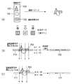
図7(A)〜(C)は、本実施の形態に係る描画命令抽出判定処理部601における判定処理及びその後の多値レンダリングとCMYK二値レンダリングの切り分けの一つの具体例を示したものである。
【0035】
図7(A)において、描画オブジェクト701乃至703を含む描画命令700が入力され、その描画命令700が論理演算付きのオブジェクト703を含む場合、事前に各オブジェクトに対応するRGBデータ(F1,F2,F3)と、色処理を行った後に二値化により作成された各オブジェクトに対応するブラシ(B1,B2,B3)とを作成しておき、走査ライン毎に、各描画オブジェクトのエッジを抽出する。
【0036】
図7(B)は、該当走査ライン710に論理演算が発生するオブジェクト703が存在している場合を示している。ここではRGBデータ(F1,F2,F3)を使用して、1走査ライン分の多値ビットマップデータを作成する。即ち、エッジ「0」と「1」の間ではオブジェクト701のRGBデータ(F1)、エッジ「1」と「2」との間では、オブジェクト702のRGBデータ(F2)、そしてエッジ「2」と「3」との間では、オブジェクト703のRGBデータ(F3)が配置される。その後、色処理、二値化処理を行って、その走査ラインの二値ビットマップデータ720を作成する。
【0037】
図7(C)は、該当走査ライン711に論理演算が発生するオブジェクト703が存在しない場合を示している。この場合は、エッジ「A」と「B」との間にオブジェクト701の二値ブラシ(B1)を、そしてエッジ「B」と「C」との間にオブジェクト702の二値ブラシ(B2)を貼り付けることにより、二値ビットマップデータ721を作成する。
【0038】
この様にして各走査ラインの二値ビットマップデータを作成し、最後に全ての走査ライン分の二値ビットマップデータをまとめることで、そのページ全体の二値ビットマップデータを作成できる。
【0039】
もちろん、二値化される際の位相などは、図7(A)と図7(B)とで完全に合わせるので、切り替え等で不正な描画は起こりえない。
【0040】
図8は、本実施の形態に係るプリンタドライバ11による印刷処理を説明するフローチャートである。
【0041】
まず入力装置4から印刷を実行するように命令が入力されるとOS9がそのメッセージを受け取る。OS9は現在アクティブであるアプリケーション10に印刷実行メッセージを送る。これによりアプリケーション10は、そのメッセージをOS9が認識できるコマンドに変換して、印刷するデータやコマンドのメッセージを送る。これによりOS9は、ドライバ11が認識できるコマンドに変換して、メッセージを送ることにより開始される。
【0042】
まずステップS1で、ドライバ11に初期化用のメッセージが送られてくると、主記憶装置2のビットマップデータを格納する領域や、描画命令の格納領域を主記憶装置2のメモリ空間に配置して、その内容をクリアする。次にステップS2に進み、ドライバ11はOS9から送られてくる描画命令を、上から並べながら格納する。この格納処理を、ページの描画命令が全て完了するまで行う。
【0043】
こうして全ての描画命令が格納領域に格納されるとステップS4に進み、その格納された全ての描画命令の色に対して色処理を行う。そしてステップS5に進み、その色(CMYK多値)に対して二値化処理を行ってブラシを作成する。
【0044】
こうして色処理、ブラシ作成が終了するとステップS6に進み、ページ上部から走査ラインに注目し、その走査ラインに存在する描画命令を抽出する。そしてステップS7で、その抽出された描画命令が全て上書きであり、論理演算や透過属性が存在しないかどうかを判定する。全て上書きで論理演算や透過属性が存在しない場合はステップS8に進み、CMYKの二値レンダリングを行う。これは走査ラインに対し、オブジェクトのエッジを抽出し、そのエッジを整数化し、そのエッジ内にステップS5で作成した、そのオブジェクトのブラシを貼り付ける処理を行う。その結果、走査ライン分のCMYK二値ビットマップデータが作成される。そしてステップS12に進み、そのページの全ての走査ラインに対する処理が完了したかを調べ、完了していない時はステップS6に戻り、前述の処理を実行する。
【0045】
一方、ステップS7で、抽出された描画命令に一つでも上書き以外の論理演算や透過属性が存在する場合はステップS9に進み、多値レンダリングを行う。これは走査ラインに対し、オブジェクトのエッジを抽出し、そのエッジを整数化し、そのエッジ内に元々のオブジェクトの色(RGB多値)を貼り付ける処理である。その結果、走査ライン分のRGB多値ビットマップデータが作成される。次にステップS10に進み、この走査ライン分のビットマップデータに対して色処理を実行し、次にステップS11で、このビットマップデータに対して二値化処理を実行することにより、走査ライン分のCMYK二値ビットマップデータが作成される。そしてステップS12に進み、ページ内の全走査ラインに対して行うまで、前述の処理を繰り返し実行する。
【0046】
以上説明した本願発明の実施の形態は、論理演算が指定されている(上書き処理では済まない)描画命令の描画領域に対しては、元の画像の色空間のままで多値ビットマップに展開(レンダリング)し、その後で色補正、別の色空間への色変換を行って最後に二値化し、論理演算が指定されていない描画命令の描画領域に対しては、最初に色補正、別の色空間への色変換を行い、最後に二値化してレンダリングすることを特徴としている。このように描画命令単位ではなく、最終的な描画領域単位での判断が必要となるため、一旦、ページ分の全描画命令を格納することが必要不可欠となる。この場合、実際はY方向、X方向へのソートも行う。本実施の形態では、スプールしたデータを走査ライン単位で上から順にビットマップ化しており、このようなビットマップ化が特徴となっている。
【0047】
そして、その走査ラインに、上書き処理の描画命令だけを含む場合は、第2レンダリング手段(n値ビットマップ展開)でn値ビットマップに変換する。一方、その走査ラインに一つでも上書き以外の描画命令が含まれる場合は、第1レンダリング手段(多値ビットマップ展開)で24ビットのビットマップを作成し、その24ビットのビットマップに色処理を行ってCMYK32ビットのビットマップに変換し、その後、2値化処理を実行して2値化ビットマップを作成することを特徴としている。
【0048】
尚、ここで第1レンダリング手段と第2レンダリング手段において処理する色変換処理やn(2)値化処理の内容は全く同じであり、違いは、第1レンダリング手段では、ビットマップ展開してから色変換やn値化処理をしているのに対し、第2レンダリング手段では、色変換やn値化処理をしてからビットマップ展開している点が異なっている。つまり、上書き処理の描画命令だけが含まれている場合には第1レンダリング(多値レンダリング)を使用しても、パフォーマンス以外の出力は同じになる。
【0049】
よって、「上書き処理では済まない描画命令が存在する走査ラインに対しては、元の画像の色空間のままで多値ビットマップに展開(レンダリング)し、その後で色補正、別の色空間への色変換処理を行って最後にn(2)値化する(第1レンダリング)」のに対し、「上書き処理だけで済む描画命令だけが含まれている走査ラインに対しては、最初に色補正、別の色空間への色変換処理を行い、n値化してパターンを作成してからレンダリングする(第2レンダリング)」ことになる。
【0050】
因みに、例えば描画命令として1cm四方の矩形があったとすると、解像度600dpiの場合、この矩形の画素数は約60000になる。つまり、多値レンダリングでは、60000点の画素データをビットマップ化し、60000点に対してRGB→CMYKへの色変換を実行し、60000点に対して二値化処理を行う必要がある。これに対して第2レンダリング手段では、ディザマトリクスが16×16=256の場合、256点に対してRGB→CMYKへの色変換を実行し、256点に対して2値化処理を実行して256点分のパターンを作成し、それを60000点の領域に貼り付けることでビットマップ化をすれば良いため、極端にパフォーマンスアップの向上を図れることになる。
【0051】
[その他の実施の形態]
なお本発明は、複数の機器(例えばホストコンピュータ、インタフェイス機器、リーダ、プリンタなど)から構成されるシステムに適用しても、一つの機器からなる装置(例えば、複写機、ファクシミリ装置など)に適用しても良い。
【0052】
また、本発明の目的は、前述した実施形態の機能を実現するソフトウェアのプログラムコードを記録した記憶媒体を、システムあるいは装置に供給し、そのシステムあるいは装置のコンピュータ(またはCPUまたはMPU)が記憶媒体に格納されたプログラムコードを読み出し実行することによっても達成されることは言うまでもない。
【0053】
この場合、記憶媒体から読み出されたプログラムコード自体が前述した実施形態の機能を実現することになり、そのプログラムコードを記憶した記憶媒体は本発明を構成することになる。
【0054】
プログラムコードを供給するための記憶媒体としては、例えば、フロッピィディスク、ハードディスク、光ディスク、光磁気ディスク、CD−ROM、CD−R、磁気テープ、不揮発性のメモリカード、ROMなどを用いることが出来る。また、コンピュータが読み出したプログラムコードを実行することにより、前述した実施形態の機能が実現されるだけでなく、そのプログラムコードの指示に基づき、コンピュータ上で稼動しているOS(オペレーティングシステム)などが実際の処理の一部を行い、その処理によって前述した実施形態の機能が実現される場合も含まれることは言うまでもない。
【0055】
さらに、記憶媒体から読み出されたプログラムコードが、コンピュータに挿入された機能拡張ボードやコンピュータに接続された機能拡張ユニットに備わるメモリに書き込まれた後、そのプログラムコードの指示に基づき、その機能拡張ボードや機能拡張ユニットに備わるCPUなどが実際の処理の一部または全部を行い、その処理によって前述した実施の形態の機能が実現される場合も含まれることは言うまでもない。
【0056】
〔他の実施の形態〕
実施の形態ではホスト側の処理という形であったが、これをプリンタ側の処理とし、描画命令を例えばPDLコマンドとしてプリンタ内で実現しても全く同様の処理となる。
【0057】
以上説明した本実施の形態の趣旨は以下のような実施態様で表わすことができる。
【0058】
[実施態様1] 印刷データを出力して印刷を実行させる印刷制御装置であって、
描画命令を入力し、ページ分の描画命令を格納する格納手段と、
1ライン毎に該当する描画命令を多値ビットマップデータに展開し、前記多値ビットマップデータに対して色処理及びn値化処理を行う第1レンダリング手段と、
前記描画命令に対し、当該描画命令の色毎に色処理及びn値化処理を行ってn値化パターンとして格納しておき、当該n値化パターンを前記描画命令の該当領域に貼り付けることでn値ビットマップデータに展開する第2レンダリング手段と、
前記描画命令が上書きができない描画命令を含むかどうかを判断する判断手段と、
前記判断手段により前記上書きができない描画命令を含むと判断されると前記第1レンダリング手段を使用し、そうでない時は前記第2レンダリング手段を使用するように制御する制御手段と、
を有することを特徴とする印刷制御装置。
【0059】
[実施態様2] 前記nの値は2であることを特徴とする実施態様1に記載の印刷制御装置。
【0060】
[実施態様3] 前記第1レンダリング手段は、
前記描画命令を基に多値ビットマップデータを生成する手段と、
前記多値ビットマップデータの色補正を行う第1色補正手段と、
前記第1色補正手段により色補正した前記多値ビットマップデータの色を別の色空間の多値ビットマップデータに変換する第1色変換手段と、
前記第1色変換手段により色変換された多値ビットマップデータを2値化する2値化手段とを有することを特徴とする実施態様2に記載の印刷制御装置。
【0061】
[実施態様4] 前記第2レンダリング手段は、
前記描画命令に含まれる画像の色を補正する第2色補正手段と、
前記第2色補正手段により色補正した画像の色を別の色空間の色に変換する第2色変換手段と、
前記第2色変換手段により色変換された画像の画像データを2値化して2値化パターンを作成する画像2値化手段と、
前記画像2値化手段により2値化された2値化パターンに基づいて2値ビットマップデータを作成する手段と、
を有することを特徴とする実施態様2又は3に記載の印刷制御装置。
【0062】
[実施態様5] 描画命令を入力してソートしてメモリに格納する手段を更に有し、前記第1及び第2レンダリング手段は、前記メモリにソートされている順に前記描画命令を読み出して処理することを特徴とする実施態様1乃至4のいずれかに記載の印刷制御装置。
【0063】
[実施態様6] 前記ソート順は、ページの上部から下部に向かう方向であることを特徴とする実施態様5に記載の印刷制御装置。
【0064】
[実施態様7] 印刷データを出力して印刷を実行させる印刷制御方法であって、
描画命令を入力し、ページ分の描画命令をメモリに格納する格納工程と、
1ライン毎に該当する描画命令を多値ビットマップデータに展開し、前記多値ビットマップデータに対して色処理及びn値化処理を行う第1レンダリング工程と、
前記描画命令に対し、当該描画命令の色毎に色処理及びn値化処理を行ってn値化パターンとして格納しておき、当該n値化パターンを前記描画命令の該当領域に貼り付けることでn値ビットマップデータに展開する第2レンダリング工程と、
前記描画命令が上書きできない描画命令を含むかどうかを判断する判断工程と、
前記判断工程で前記上書きできない描画命令を含むと判断されると前記第1レンダリング工程を使用し、そうでない時は前記第2レンダリング工程を使用するように制御する制御工程と、
を有することを特徴とする印刷制御方法。
【0065】
[実施態様8] 前記nの値は2であることを特徴とする実施態様1に記載の印刷制御方法。
【0066】
[実施態様9] 前記第1レンダリング工程は、
前記描画命令を基に多値ビットマップデータを生成する工程と、
前記多値ビットマップデータの色補正を行う第1色補正工程と、
前記第1色補正工程で色補正した前記多値ビットマップデータの色を別の色空間の多値ビットマップデータに変換する第1色変換工程と、
前記第1色変換工程で色変換された多値ビットマップデータを2値化する2値化工程とを有することを特徴とする実施態様8に記載の印刷制御方法。
【0067】
[実施態様10] 前記第2レンダリング工程は、
前記描画命令に含まれる画像の色を補正する第2色補正工程と、
前記第2色補正工程で色補正した画像の色を別の色空間の色に変換する第2色変換工程と、
前記第2色変換工程で色変換された画像の画像データを2値化して2値化パターンを作成する画像2値化工程と、
前記画像2値化工程で2値化された2値化パターンに基づいて2値ビットマップデータを作成する工程と、
を有することを特徴とする実施態様8又は9に記載の印刷制御方法。
【0068】
[実施態様11] 描画命令を入力してソートしてメモリに格納する工程を更に有し、前記第1及び第2レンダリング工程では、前記メモリにソートされている順に前記描画命令を読み出して処理することを特徴とする実施態様7乃至10のいずれかに記載の印刷制御方法。
【0069】
[実施態様12] 前記ソート順は、ページの上部から下部に向かう方向であることを特徴とする実施態様11に記載の印刷制御方法。
【0070】
以上説明したように本実施の形態によれば、描画命令に対し、高速に高品質なビットマップデータを作成することが出来るようになる。
【0071】
【発明の効果】
以上説明したように本発明によれば、従来のCMYK高速モードで発生する問題を解決して、論理演算の指定を含むデータに対しても高品位モードと同様の出力が得られるという効果がある。
【図面の簡単な説明】
【図1】図1は、本発明の実施の形態に係る情報処理システムの構成の一例を示すブロック図である。
【図2】図2は、本実施の形態に係る中央処理装置と主記憶装置のプログラム構成を説明する概念図である。
【図3】図3は、従来技術で説明したプリンタドライバによる高品位印刷モードでの処理の流れを示す流れ図である。
【図4】図4は、従来技術で説明したプリンタドライバによるRGB高速印刷モードでの処理の流れを示す流れ図である。
【図5】図5は、従来技術で説明したプリンタドライバによるCMYK高速印刷モードでの処理の流れを示す流れ図である。
【図6】図6は、本発明の実施の形態に係る高品位高速印刷モードの処理の流れを示す流れ図である。
【図7】図7は、本実施の形態における、走査ライン単位で多値レンダリングとCMYKレンダリングを切り替える処理を説明する図である。
【図8】図8は本実施の形態に係る情報処理システムにおける画像処理を説明するフローチャートである。[0001]
BACKGROUND OF THE INVENTION
The present invention relates to a print control apparatus that outputs print data and prints it. And the method It is about.
[0002]
[Prior art]
Conventionally, color image data processing by a printer driver is roughly divided into the following three types. First, in response to a drawing command from the OS, bitmap data is expanded in the multi-value bitmap area (multi-value rendering), and when all the drawing commands are processed, the entire multi-value bitmap area is This is a method (high quality mode) for performing color processing (color correction processing, multi-value color conversion processing, binarization processing).
[0003]
Second, color processing (color correction) is performed on the drawing command from the OS, binarization processing is performed on the original RGB data to create a brush, and then the bit data is stored in the binary bitmap area. (RGB binary rendering) and color processing (binary color conversion) is performed on the binary bitmap area (RGB high-speed mode) when processing of all drawing commands is completed.
[0004]
Third, color processing (color correction, multi-value color conversion) is performed in response to a drawing command from the OS, binarization processing is performed on CMYK data created by color conversion, and then a brush is created. This is a method (CMYK binary rendering) method (CMYK high-speed mode) for developing bit data in a binary bitmap area.
[0005]
However, in the first high-definition mode, multi-value bitmap data is expanded and color processing is executed on the entire area, so a large amount of memory capacity is used, and color processing and binarization processing are performed for all pixels. Poor performance because it must be done in units.
[0006]
The second RGB high-speed mode creates CMYK data to be finally printed from binarized RGB bitmap data, and in particular, UCR (represents black data with CMY ink or K ink). Since the balance cannot be changed, the image quality is inferior.
[0007]
Further, in the case of the third CMYK high speed mode, the image quality of the printed image is almost the same as that in the high quality mode, and the performance is considered to be close to the RGB high speed mode.
[0008]
[Problems to be solved by the invention]
However, in this CMYK high-speed mode, the logical operation processing that is premised on primary independence is not primary independent, that is, it is necessary to perform in the CMYK color space converted from the RGB color space. It is difficult to obtain. Also, depending on the device, special processing is executed when a specific logical operation occurs, or a defect remains for a logical operation with a low appearance frequency. For this reason, there are few products that perform print processing using this CMYK high-speed mode mechanism.
[0009]
The present invention has been made in view of the above-described conventional example, and solves the problem that occurs in the conventional CMYK high-speed mode, so that the same output as in the high-quality mode can be obtained for data including the designation of the logical operation. Control device And the method The purpose is to provide.
[0010]
[Means for Solving the Problems]
In order to achieve the above object, the printing control apparatus of the present invention has the following configuration. That is,
A print control apparatus that outputs print data and executes printing,
Storage means for inputting drawing commands and storing drawing commands for a page;
First rendering means for expanding a rendering command corresponding to each line into multi-value bitmap data, and performing color processing and n-value processing on the multi-value bitmap data;
For the drawing command, color processing and n-value conversion processing are performed for each color of the drawing command and stored in the form of an n-value pattern, and the n-value pattern is pasted to the corresponding area of the drawing command. Second rendering means for developing into n-value bitmap data,
Determining means for determining whether the drawing command includes a drawing command that cannot be overwritten;
When it is determined by the determination means that it includes a drawing command that cannot be overwritten The edges of the drawing command object are extracted for each line, and the objects between the edges are extracted. And control means for controlling to use the first rendering means and to use the second rendering means when not.
In order to achieve the above object, the printing control method of the present invention includes the following steps. That is,
A print control method for outputting print data and executing printing,
A storage step of inputting a drawing command and storing a drawing command for a page in a memory;
A first rendering step of developing a rendering command corresponding to each line into multi-value bitmap data, and performing color processing and n-value processing on the multi-value bitmap data;
For the drawing command, color processing and n-value conversion processing are performed for each color of the drawing command and stored as an n-valued pattern, and the n-valued pattern is pasted on a corresponding area of the drawing command. a second rendering step for developing n-value bitmap data;
Determining whether the drawing command includes a drawing command that cannot be overwritten;
When it is determined in the determination step that the drawing command cannot be overwritten The edges of the drawing command object are extracted for each line, and the objects between the edges are extracted. And a control step of controlling to use the first rendering step, and to use the second rendering step otherwise.
[0011]
DETAILED DESCRIPTION OF THE INVENTION
Preferred embodiments of the present invention will be described below in detail with reference to the accompanying drawings. In this embodiment, an example is described in which the present invention is applied to a system in which a host device and a printing device are connected by a Centronics interface, but the present invention is not limited to this. That is, this interface format is not an important component in the present invention, and can be easily applied to infrared communication, wireless communication, an interface defined by USB or IEEE 1394 standard, or other various network connection forms. is there.
[0012]
FIG. 1 is a block diagram showing an example of the configuration of the information processing system according to the embodiment of the present invention.
[0013]
In FIG. 1,
[0014]
The
[0015]
In the present embodiment, the
[0016]
FIG. 2 is a block diagram illustrating functional configurations of the
[0017]
Here, the data related to the control program for executing the image processing method according to the present embodiment stored in the medium reading device 6 or the
[0018]
FIG. 3 is a flowchart showing the flow of processing in the high-quality print mode by the
[0019]
When a drawing command is received from the
[0020]
FIG. 4 is a diagram showing a flow of processing in the RGB high-speed printing mode by the
[0021]
When a drawing command is received from the
[0022]
When such processing is executed, the printing process becomes faster, but UCR processing (designation of whether black data is output in K or CMY) is not effective due to binary color conversion (RGB → CMYK). The output result is not optimal.
[0023]
FIG. 5 is a diagram showing a flow of processing in the CMYK high-speed printing mode by the
[0024]
When a drawing command is received from the
[0025]
In this high-speed printing mode, color processing (color correction, color conversion, binarization processing) is the same as the high-quality printing mode in FIG. 4 described above, and therefore generally the same output as the high-quality mode is created. Can do. However, when performing drawing processing that must perform logical operation processing, the logical operation is performed on non-primary independent data such as CMYK instead of RGB, which is primary independent data, resulting in an incorrect output result. May end up.
[0026]
FIG. 6 is a diagram for explaining a high-quality high-speed print mode by the
[0027]
In this embodiment, when a drawing command is passed from the
[0028]
When the storage
[0029]
In this CMYK binary rendering, when there is a possibility of drawing fraud, that is, when there is no logical operation processing or transparency processing, a color correction processing unit is performed in accordance with the processing flow of the CMYK high-speed printing mode shown in FIG. Color processing (color correction) by 602 and color conversion processing by the color
[0030]
On the other hand, if the drawing command extraction
[0031]
Although the binary bit map data obtained by binarizing the data to be output to the
[0032]
Further, the color
[0033]
Further, it is not always necessary to stick to a single scanning line of a page, and a multi-line rendering system and a CMYK binary rendering system can be realized in the same manner even if a plurality of lines are processed together unless the system is switched.
[0034]
FIGS. 7A to 7C show one specific example of determination processing in the rendering command extraction
[0035]
In FIG. 7A, when a
[0036]
FIG. 7B shows a case where an
[0037]
FIG. 7C shows a case where there is no
[0038]
In this way, binary bitmap data for each scanning line is created, and finally, binary bitmap data for all scanning lines is collected, so that binary bitmap data for the entire page can be created.
[0039]
Of course, since the phase at the time of binarization is completely matched between FIG. 7A and FIG. 7B, illegal drawing cannot occur by switching or the like.
[0040]
FIG. 8 is a flowchart for explaining print processing by the
[0041]
First, when a command is input from the
[0042]
First, in
[0043]
When all drawing commands are stored in the storage area in this way, the process proceeds to step S4, and color processing is performed on the colors of all the stored drawing commands. In step S5, the color (CMYK multivalue) is binarized to create a brush.
[0044]
When the color processing and the brush creation are thus completed, the process proceeds to step S6, where the scanning line is noticed from the top of the page, and the drawing command existing in the scanning line is extracted. In step S7, it is determined whether all of the extracted drawing commands are overwritten and there is no logical operation or transparency attribute. If all are overwritten and no logical operation or transparency attribute exists, the process advances to step S8 to perform CMYK binary rendering. In this process, the edge of the object is extracted from the scanning line, the edge is converted to an integer, and the object brush created in step S5 is pasted into the edge. As a result, CMYK binary bitmap data for the scanning line is created. Then, the process proceeds to step S12 to check whether or not the processing for all the scanning lines on the page is completed. If not completed, the process returns to step S6 to execute the above-described processing.
[0045]
On the other hand, if at least one logical operation or transparency attribute other than overwriting exists in the extracted drawing command in step S7, the process proceeds to step S9 to perform multi-value rendering. This is a process of extracting an edge of an object from a scanning line, converting the edge into an integer, and pasting the original object color (RGB multivalue) into the edge. As a result, RGB multilevel bitmap data for the scanning line is created. In step S10, color processing is performed on the bitmap data for the scanning line. Next, in step S11, binarization processing is performed on the bitmap data, thereby obtaining the scanning line data. CMYK binary bitmap data is created. Then, the process proceeds to step S12, and the above-described processing is repeatedly executed until it is performed for all scanning lines in the page.
[0046]
In the embodiment of the present invention described above, for a drawing area of a drawing command for which a logical operation is specified (not overwritten), a multi-value bitmap is developed in the original image color space ( Rendering), then color correction, color conversion to another color space, and finally binarization, for the drawing area of the drawing command for which no logical operation is specified, first color correction, It is characterized by performing color conversion to a color space and finally binarizing and rendering. Thus, since it is necessary to make a determination not in units of drawing commands but in units of final drawing areas, it is indispensable to temporarily store all drawing commands for one page. In this case, the sorting is actually performed in the Y direction and the X direction. In the present embodiment, the spooled data is bitmapped in order from the top in units of scanning lines, and such bitmapping is a feature.
[0047]
If the scanning line includes only a drawing command for overwriting, it is converted into an n-value bitmap by the second rendering means (n-value bitmap development). On the other hand, when at least one drawing command other than overwriting is included in the scan line, a 24-bit bitmap is created by the first rendering means (multi-valued bitmap development), and color processing is performed on the 24-bit bitmap. Is converted into a CMYK 32-bit bitmap, and then binarization processing is executed to create a binary bitmap.
[0048]
Here, the contents of the color conversion process and the n (2) value conversion process processed in the first rendering unit and the second rendering unit are exactly the same, and the difference is that the first rendering unit performs the bitmap development. While the color conversion and n-value processing are performed, the second rendering means is different in that the bitmap conversion is performed after the color conversion and n-value processing. In other words, when only the rendering processing drawing command is included, the output other than the performance is the same even if the first rendering (multi-value rendering) is used.
[0049]
Therefore, for a scanning line having a rendering command that cannot be overwritten, it is expanded (rendered) into a multi-valued bitmap in the original image color space, and then color correction is performed to another color space. In contrast to “converting color to n (2) last (first rendering)”, for a scanning line including only a rendering command that only requires overwriting, color correction is performed first. Then, a color conversion process into another color space is performed, and a pattern is generated by rendering it into n-values and then rendered (second rendering) ”.
[0050]
For example, if there is a 1 cm square as a drawing command, the number of pixels of this rectangle is about 60000 when the resolution is 600 dpi. That is, in multi-level rendering, it is necessary to convert 60000 points of pixel data into bitmaps, execute color conversion from RGB to CMYK for 60000 points, and perform binarization processing for 60000 points. On the other hand, in the second rendering means, when the dither matrix is 16 × 16 = 256, color conversion from RGB to CMYK is executed for 256 points, and binarization processing is executed for 256 points. Since it is sufficient to create a pattern for 256 points and paste it into an area of 60000 points to form a bitmap, it is possible to extremely improve performance.
[0051]
[Other embodiments]
Note that the present invention can be applied to a system composed of a plurality of devices (for example, a host computer, an interface device, a reader, a printer, etc.), or an apparatus composed of a single device (for example, a copier, a facsimile machine, etc.). It may be applied.
[0052]
Another object of the present invention is to supply a storage medium storing software program codes for realizing the functions of the above-described embodiments to a system or apparatus, and the computer (or CPU or MPU) of the system or apparatus stores the storage medium. Needless to say, this can also be achieved by reading and executing the program code stored in.
[0053]
In this case, the program code itself read from the storage medium realizes the functions of the above-described embodiments, and the storage medium storing the program code constitutes the present invention.
[0054]
As a storage medium for supplying the program code, for example, a floppy disk, a hard disk, an optical disk, a magneto-optical disk, a CD-ROM, a CD-R, a magnetic tape, a nonvolatile memory card, a ROM, or the like can be used. Further, by executing the program code read by the computer, not only the functions of the above-described embodiments are realized, but also an OS (operating system) operating on the computer based on the instruction of the program code. It goes without saying that a part of the actual processing is performed and the functions of the above-described embodiments are realized by the processing.
[0055]
Further, after the program code read from the storage medium is written to a memory provided in a function expansion board inserted into the computer or a function expansion unit connected to the computer, the function expansion is performed based on the instruction of the program code. It goes without saying that the CPU or the like provided in the board or the function expansion unit performs part or all of the actual processing and the functions of the above-described embodiments are realized by the processing.
[0056]
[Other Embodiments]
In the embodiment, the process is a process on the host side. However, this process is a process on the printer side, and if the drawing command is realized in the printer as a PDL command, for example, the process is exactly the same.
[0057]
The gist of the present embodiment described above can be expressed by the following embodiments.
[0058]
[Embodiment 1] A print control apparatus for outputting print data and executing printing,
Storage means for inputting drawing commands and storing drawing commands for a page;
First rendering means for expanding a rendering command corresponding to each line into multi-value bitmap data, and performing color processing and n-value processing on the multi-value bitmap data;
For the drawing command, color processing and n-value conversion processing are performed for each color of the drawing command and stored as an n-valued pattern, and the n-valued pattern is pasted on a corresponding area of the drawing command. second rendering means for developing n-value bitmap data;
Determining means for determining whether the drawing command includes a drawing command that cannot be overwritten;
Control means for controlling to use the first rendering means when it is determined by the determination means to include the rendering instruction that cannot be overwritten, and to use the second rendering means otherwise.
A printing control apparatus comprising:
[0059]
[Embodiment 2] The print control apparatus according to
[0060]
[Embodiment 3] The first rendering means includes:
Means for generating multi-valued bitmap data based on the drawing command;
First color correction means for performing color correction of the multi-value bitmap data;
First color conversion means for converting the color of the multi-value bitmap data color-corrected by the first color correction means into multi-value bitmap data of another color space;
The printing control apparatus according to
[0061]
[Embodiment 4] The second rendering means includes:
Second color correction means for correcting the color of the image included in the drawing command;
Second color conversion means for converting the color of the image color-corrected by the second color correction means into a color of another color space;
Image binarization means for binarizing image data of an image color-converted by the second color conversion means to create a binarization pattern;
Means for creating binary bitmap data based on the binarization pattern binarized by the image binarization means;
The printing control apparatus according to
[0062]
[Embodiment 5] It further has means for inputting drawing commands, sorting them, and storing them in a memory, and the first and second rendering means read and process the drawing commands in the order sorted in the memory. The printing control apparatus according to any one of the first to fourth embodiments.
[0063]
[Embodiment 6] The print control apparatus according to
[0064]
[Embodiment 7] A print control method for outputting print data and executing printing,
A storage step of inputting a drawing command and storing a drawing command for a page in a memory;
A first rendering step of developing a rendering command corresponding to each line into multi-value bitmap data, and performing color processing and n-value processing on the multi-value bitmap data;
For the drawing command, color processing and n-value conversion processing are performed for each color of the drawing command and stored as an n-valued pattern, and the n-valued pattern is pasted on a corresponding area of the drawing command. a second rendering step for developing n-value bitmap data;
Determining whether the drawing command includes a drawing command that cannot be overwritten;
A control step of controlling to use the first rendering step when it is determined that the rendering command includes the rendering instruction that cannot be overwritten, and to use the second rendering step otherwise.
A printing control method characterized by comprising:
[0065]
[Embodiment 8] The print control method according to
[0066]
[Embodiment 9] The first rendering step includes:
Generating multi-value bitmap data based on the drawing command;
A first color correction step of performing color correction of the multi-value bitmap data;
A first color conversion step of converting the color of the multi-value bitmap data color-corrected in the first color correction step into multi-value bitmap data of another color space;
The print control method according to
[0067]
[Embodiment 10] The second rendering step includes
A second color correction step of correcting the color of the image included in the drawing command;
A second color conversion step of converting the color of the image color-corrected in the second color correction step into a color of another color space;
An image binarization step for binarizing image data of the image color-converted in the second color conversion step to create a binarization pattern;
Creating binary bitmap data based on the binarization pattern binarized in the image binarization step;
The printing control method according to
[0068]
[Embodiment 11] The method further includes a step of inputting drawing commands, sorting them, and storing them in a memory. In the first and second rendering steps, the drawing commands are read and processed in the order sorted in the memory. The printing control method according to any one of
[0069]
[Embodiment 12] The printing control method according to
[0070]
As described above, according to the present embodiment, high-quality bitmap data can be created at high speed in response to a drawing command.
[0071]
【The invention's effect】
As described above, according to the present invention, it is possible to solve the problem that occurs in the conventional CMYK high-speed mode, and to obtain the same output as that in the high-quality mode for data including the designation of the logical operation. .
[Brief description of the drawings]
FIG. 1 is a block diagram showing an example of a configuration of an information processing system according to an embodiment of the present invention.
FIG. 2 is a conceptual diagram illustrating a program configuration of a central processing unit and a main storage device according to the present embodiment.
FIG. 3 is a flowchart illustrating a process flow in a high-quality print mode by a printer driver described in the related art.
FIG. 4 is a flowchart showing a processing flow in an RGB high-speed printing mode by a printer driver described in the related art.
FIG. 5 is a flowchart illustrating a process flow in a CMYK high-speed printing mode by a printer driver described in the related art.
FIG. 6 is a flowchart showing a flow of processing in a high-quality high-speed printing mode according to the embodiment of the present invention.
FIG. 7 is a diagram illustrating processing for switching between multi-value rendering and CMYK rendering in units of scan lines in the present embodiment.
FIG. 8 is a flowchart illustrating image processing in the information processing system according to the present embodiment.
Claims (12)
描画命令を入力し、ページ分の描画命令を格納する格納手段と、
1ライン毎に該当する描画命令を多値ビットマップデータに展開し、前記多値ビットマップデータに対して色処理及びn値化処理を行う第1レンダリング手段と、
前記描画命令に対し、当該描画命令の色毎に色処理及びn値化処理を行ってn値化パターンの形式で格納しておき、当該n値化パターンを前記描画命令の該当領域に貼り付けることでn値ビットマップデータに展開する第2レンダリング手段と、
前記描画命令が上書きができない描画命令を含むかどうかを判断する判断手段と、
前記判断手段により前記上書きができない描画命令を含むと判断されると、前記1ライン毎に当該描画命令のオブジェクトのエッジを抽出し、該エッジ間のオブジェクトに前記第1レンダリング手段を使用し、そうでない時は前記第2レンダリング手段を使用するように制御する制御手段と、
を有することを特徴とする印刷制御装置。A print control apparatus that outputs print data and executes printing,
Storage means for inputting drawing commands and storing drawing commands for a page;
First rendering means for expanding a rendering command corresponding to each line into multi-value bitmap data, and performing color processing and n-value processing on the multi-value bitmap data;
For the drawing command, color processing and n-value conversion processing are performed for each color of the drawing command and stored in the form of an n-value pattern, and the n-value pattern is pasted to the corresponding area of the drawing command. Second rendering means for developing into n-value bitmap data,
Determining means for determining whether the drawing command includes a drawing command that cannot be overwritten;
If it is determined by the determining means that the drawing command that cannot be overwritten is included, an edge of the object of the drawing command is extracted for each line, and the first rendering means is used for the object between the edges. If not, control means for controlling to use the second rendering means;
A printing control apparatus comprising:
前記描画命令を基に多値ビットマップデータを生成する手段と、Means for generating multi-valued bitmap data based on the drawing command;
前記多値ビットマップデータの色補正を行う第1色補正手段と、First color correction means for performing color correction of the multi-value bitmap data;
前記第1色補正手段により色補正した前記多値ビットマップデータの色を別の色空間の多値ビットマップデータに変換する第1色変換手段と、First color conversion means for converting the color of the multi-value bitmap data color-corrected by the first color correction means into multi-value bitmap data of another color space;
前記第1色変換手段により色変換された多値ビットマップデータを2値化する2値化手段とを有することを特徴とする請求項2に記載の印刷制御装置。The print control apparatus according to claim 2, further comprising: binarization means for binarizing the multi-value bitmap data color-converted by the first color conversion means.
前記描画命令に含まれる画像の色を補正する第2色補正手段と、Second color correction means for correcting the color of the image included in the drawing command;
前記第2色補正手段により色補正した画像の色を別の色空間の色に変換する第2色変換手段と、Second color conversion means for converting the color of the image color-corrected by the second color correction means into a color of another color space;
前記第2色変換手段により色変換された画像の画像データを2値化して2値化パターンを作成する画像2値化手段と、Image binarization means for binarizing image data of an image color-converted by the second color conversion means to create a binarization pattern;
前記画像2値化手段により2値化された2値化パターンに基づいて2値ビットマップデータを作成する手段と、Means for creating binary bitmap data based on the binarization pattern binarized by the image binarization means;
を有することを特徴とする請求項2又は3に記載の印刷制御装置。The print control apparatus according to claim 2, further comprising:
描画命令を入力し、ページ分の描画命令をメモリに格納する格納工程と、
1ライン毎に該当する描画命令を多値ビットマップデータに展開し、前記多値ビットマップデータに対して色処理及びn値化処理を行う第1レンダリング工程と、
前記描画命令に対し、当該描画命令の色毎に色処理及びn値化処理を行ってn値化パターンとして格納しておき、当該n値化パターンを前記描画命令の該当領域に貼り付けることでn値ビットマップデータに展開する第2レンダリング工程と、
前記描画命令が上書きできない描画命令を含むかどうかを判断する判断工程と、
前記判断工程で前記上書きできない描画命令を含むと判断されると、前記1ライン毎に当該描画命令のオブジェクトのエッジを抽出し、該エッジ間のオブジェクトに前記第1レンダリング工程を使用し、そうでない時は前記第2レンダリング工程を使用するように制御する制御工程と、
を有することを特徴とする印刷制御方法。A print control method for outputting print data and executing printing,
A storage step of inputting a drawing command and storing a drawing command for a page in a memory;
A first rendering step of developing a rendering command corresponding to each line into multi-value bitmap data, and performing color processing and n-value processing on the multi-value bitmap data;
For the drawing command, color processing and n-value conversion processing are performed for each color of the drawing command and stored as an n-valued pattern, and the n-valued pattern is pasted on a corresponding area of the drawing command. a second rendering step for developing n-value bitmap data;
Determining whether the drawing command includes a drawing command that cannot be overwritten;
If it is determined in the determination step that the drawing command that cannot be overwritten is included, an edge of the object of the drawing command is extracted for each line, and the first rendering step is used for an object between the edges, and otherwise A control process for controlling to use the second rendering process at times;
A printing control method characterized by comprising:
前記描画命令を基に多値ビットマップデータを生成する工程と、Generating multi-value bitmap data based on the drawing command;
前記多値ビットマップデータの色補正を行う第1色補正工程と、A first color correction step of performing color correction of the multi-value bitmap data;
前記第1色補正工程で色補正した前記多値ビットマップデータの色を別の色空間の多値ビットマップデータに変換する第1色変換工程と、A first color conversion step of converting the color of the multi-value bitmap data color-corrected in the first color correction step into multi-value bitmap data of another color space;
前記第1色変換工程で色変換された多値ビットマップデータを2値化する2値化工程とを有することを特徴とする請求項8に記載の印刷制御方法。The print control method according to claim 8, further comprising: a binarization step of binarizing the multi-value bitmap data color-converted in the first color conversion step.
前記描画命令に含まれる画像の色を補正する第2色補正工程と、A second color correction step of correcting the color of the image included in the drawing command;
前記第2色補正工程で色補正した画像の色を別の色空間の色に変換する第2色変換工程と、A second color conversion step of converting the color of the image color-corrected in the second color correction step into a color of another color space;
前記第2色変換工程で色変換された画像の画像データを2値化して2値化パターンを作成する画像2値化工程と、An image binarization step for binarizing image data of the image color-converted in the second color conversion step to create a binarization pattern;
前記画像2値化工程で2値化された2値化パターンに基づいて2値ビットマップデータを作成する工程と、Creating binary bitmap data based on the binarization pattern binarized in the image binarization step;
を有することを特徴とする請求項8又は9に記載の印刷制御方法。The print control method according to claim 8, wherein the print control method is provided.
Priority Applications (4)
| Application Number | Priority Date | Filing Date | Title |
|---|---|---|---|
| JP2003035319A JP4054690B2 (en) | 2003-02-13 | 2003-02-13 | Printing control apparatus and method |
| US10/773,423 US7859713B2 (en) | 2003-02-13 | 2004-02-09 | Printing control apparatus, method and printer driver |
| EP04250698.0A EP1447768B1 (en) | 2003-02-13 | 2004-02-10 | Printing control apparatus, method and printer driver |
| CNB2004100039972A CN1287264C (en) | 2003-02-13 | 2004-02-12 | Printing control apparatus, method and printer driver |
Applications Claiming Priority (1)
| Application Number | Priority Date | Filing Date | Title |
|---|---|---|---|
| JP2003035319A JP4054690B2 (en) | 2003-02-13 | 2003-02-13 | Printing control apparatus and method |
Publications (3)
| Publication Number | Publication Date |
|---|---|
| JP2004246596A JP2004246596A (en) | 2004-09-02 |
| JP2004246596A5 JP2004246596A5 (en) | 2005-10-20 |
| JP4054690B2 true JP4054690B2 (en) | 2008-02-27 |
Family
ID=32677612
Family Applications (1)
| Application Number | Title | Priority Date | Filing Date |
|---|---|---|---|
| JP2003035319A Expired - Fee Related JP4054690B2 (en) | 2003-02-13 | 2003-02-13 | Printing control apparatus and method |
Country Status (4)
| Country | Link |
|---|---|
| US (1) | US7859713B2 (en) |
| EP (1) | EP1447768B1 (en) |
| JP (1) | JP4054690B2 (en) |
| CN (1) | CN1287264C (en) |
Families Citing this family (6)
| Publication number | Priority date | Publication date | Assignee | Title |
|---|---|---|---|---|
| US7640415B2 (en) * | 2005-03-25 | 2009-12-29 | Hitachi, Ltd. | Storage system having a first computer, a second computer connected to the first computer via a network, and a storage device system that is accessed by the second computer |
| JP2007136845A (en) * | 2005-11-18 | 2007-06-07 | Seiko Epson Corp | Printing system, image processor, printer driver, and program |
| JP2011060154A (en) * | 2009-09-11 | 2011-03-24 | Ricoh Co Ltd | Printer driver, information processor, and computer readable storage medium |
| JP5629506B2 (en) | 2010-06-28 | 2014-11-19 | キヤノン株式会社 | Method and apparatus for correcting misregistration in printing apparatus |
| JP5861689B2 (en) * | 2013-11-19 | 2016-02-16 | コニカミノルタ株式会社 | Information processing apparatus, information processing method, information processing program, and recording medium |
| JP6252225B2 (en) * | 2014-02-17 | 2017-12-27 | 株式会社リコー | Image processing apparatus, image processing method, and image forming apparatus |
Family Cites Families (7)
| Publication number | Priority date | Publication date | Assignee | Title |
|---|---|---|---|---|
| ES2139700T3 (en) * | 1993-11-19 | 2000-02-16 | Canon Kk | PRINTING DEVICE. |
| JPH0930056A (en) | 1995-07-14 | 1997-02-04 | Ricoh Co Ltd | Printer controller |
| JP3359234B2 (en) | 1996-07-31 | 2002-12-24 | キヤノン株式会社 | Image processing apparatus and method |
| US6853465B1 (en) * | 1999-05-18 | 2005-02-08 | Canon Kabushiki Kaisha | Image processing method and apparatus, and storage medium therefor |
| JP2001155147A (en) * | 1999-09-17 | 2001-06-08 | Canon Inc | Method and device for image, processing and recording medium |
| JP2001109606A (en) | 1999-10-07 | 2001-04-20 | Canon Inc | Information processor, printer, plotting control method and storage medium |
| JP2002319018A (en) | 2001-04-20 | 2002-10-31 | Fuji Xerox Co Ltd | Plotting process device and method and computer readable recording medium recording plotting process program |
-
2003
- 2003-02-13 JP JP2003035319A patent/JP4054690B2/en not_active Expired - Fee Related
-
2004
- 2004-02-09 US US10/773,423 patent/US7859713B2/en not_active Expired - Fee Related
- 2004-02-10 EP EP04250698.0A patent/EP1447768B1/en not_active Expired - Fee Related
- 2004-02-12 CN CNB2004100039972A patent/CN1287264C/en not_active Expired - Fee Related
Also Published As
| Publication number | Publication date |
|---|---|
| EP1447768A2 (en) | 2004-08-18 |
| CN1521613A (en) | 2004-08-18 |
| US20040160621A1 (en) | 2004-08-19 |
| CN1287264C (en) | 2006-11-29 |
| EP1447768A3 (en) | 2012-01-04 |
| US7859713B2 (en) | 2010-12-28 |
| JP2004246596A (en) | 2004-09-02 |
| EP1447768B1 (en) | 2019-04-10 |
Similar Documents
| Publication | Publication Date | Title |
|---|---|---|
| US7692813B2 (en) | Image processing apparatus and method, and storage medium | |
| US7505174B2 (en) | Image processing method, system and apparatus, and storage medium | |
| JPH11313213A (en) | Information processing system, information processing method and medium | |
| US8014031B2 (en) | Formation of picture image having gradation expressed by fill area and one-line image data | |
| US6429950B1 (en) | Method and apparatus for applying object characterization pixel tags to image data in a digital imaging device | |
| JP4054690B2 (en) | Printing control apparatus and method | |
| JP5684466B2 (en) | Method and computer readable medium for processing at least one pixel in a raster image buffer corresponding to objects of multiple object types | |
| JP4428743B2 (en) | Image processing method and apparatus, printer, image processing system, and storage medium | |
| JP4109785B2 (en) | Image processing apparatus and method, and computer-readable memory | |
| JP4356953B2 (en) | Image processing system, image processing apparatus, control method therefor, and storage medium | |
| JP4514168B2 (en) | Image processing system and image processing method | |
| JP3695498B2 (en) | Image processing device | |
| JPH09218959A (en) | Image processor | |
| US20060092439A1 (en) | Printer controller, image forming apparatus, image forming program | |
| JP4306841B2 (en) | Image processing apparatus and method, and computer-readable memory | |
| JP4217332B2 (en) | Image processing apparatus and method, and computer-readable memory | |
| JP3636891B2 (en) | Color image output method | |
| JP3829895B2 (en) | Image processing device | |
| JPH0993425A (en) | Image forming device | |
| JP2006140597A (en) | Device and method for printing control, computer program, and storage medium | |
| JP2003196648A (en) | Image processing method and device, its storage medium and program product | |
| JPH1051652A (en) | Information processing unit and method | |
| JPH09284548A (en) | Picture processor and method therefor | |
| JP2006350802A (en) | Printer and printing control method | |
| JPH0474660A (en) | Color printer control device |
Legal Events
| Date | Code | Title | Description |
|---|---|---|---|
| A521 | Request for written amendment filed |
Free format text: JAPANESE INTERMEDIATE CODE: A523 Effective date: 20050610 |
|
| A621 | Written request for application examination |
Free format text: JAPANESE INTERMEDIATE CODE: A621 Effective date: 20050610 |
|
| A131 | Notification of reasons for refusal |
Free format text: JAPANESE INTERMEDIATE CODE: A131 Effective date: 20070907 |
|
| A521 | Request for written amendment filed |
Free format text: JAPANESE INTERMEDIATE CODE: A523 Effective date: 20071102 |
|
| TRDD | Decision of grant or rejection written | ||
| A01 | Written decision to grant a patent or to grant a registration (utility model) |
Free format text: JAPANESE INTERMEDIATE CODE: A01 Effective date: 20071130 |
|
| A61 | First payment of annual fees (during grant procedure) |
Free format text: JAPANESE INTERMEDIATE CODE: A61 Effective date: 20071210 |
|
| FPAY | Renewal fee payment (event date is renewal date of database) |
Free format text: PAYMENT UNTIL: 20101214 Year of fee payment: 3 |
|
| R150 | Certificate of patent or registration of utility model |
Ref document number: 4054690 Country of ref document: JP Free format text: JAPANESE INTERMEDIATE CODE: R150 Free format text: JAPANESE INTERMEDIATE CODE: R150 |
|
| FPAY | Renewal fee payment (event date is renewal date of database) |
Free format text: PAYMENT UNTIL: 20111214 Year of fee payment: 4 |
|
| FPAY | Renewal fee payment (event date is renewal date of database) |
Free format text: PAYMENT UNTIL: 20121214 Year of fee payment: 5 |
|
| FPAY | Renewal fee payment (event date is renewal date of database) |
Free format text: PAYMENT UNTIL: 20131214 Year of fee payment: 6 |
|
| LAPS | Cancellation because of no payment of annual fees |