JP4049994B2 - Improvements regarding injection devices - Google Patents
Improvements regarding injection devices Download PDFInfo
- Publication number
- JP4049994B2 JP4049994B2 JP2000504909A JP2000504909A JP4049994B2 JP 4049994 B2 JP4049994 B2 JP 4049994B2 JP 2000504909 A JP2000504909 A JP 2000504909A JP 2000504909 A JP2000504909 A JP 2000504909A JP 4049994 B2 JP4049994 B2 JP 4049994B2
- Authority
- JP
- Japan
- Prior art keywords
- barrel
- injection device
- carrier
- syringe
- firing mechanism
- Prior art date
- Legal status (The legal status is an assumption and is not a legal conclusion. Google has not performed a legal analysis and makes no representation as to the accuracy of the status listed.)
- Expired - Lifetime
Links
Images


Classifications
-
- A—HUMAN NECESSITIES
- A61—MEDICAL OR VETERINARY SCIENCE; HYGIENE
- A61M—DEVICES FOR INTRODUCING MEDIA INTO, OR ONTO, THE BODY; DEVICES FOR TRANSDUCING BODY MEDIA OR FOR TAKING MEDIA FROM THE BODY; DEVICES FOR PRODUCING OR ENDING SLEEP OR STUPOR
- A61M5/00—Devices for bringing media into the body in a subcutaneous, intra-vascular or intramuscular way; Accessories therefor, e.g. filling or cleaning devices, arm-rests
- A61M5/178—Syringes
- A61M5/31—Details
- A61M5/32—Needles; Details of needles pertaining to their connection with syringe or hub; Accessories for bringing the needle into, or holding the needle on, the body; Devices for protection of needles
- A61M5/3205—Apparatus for removing or disposing of used needles or syringes, e.g. containers; Means for protection against accidental injuries from used needles
-
- A—HUMAN NECESSITIES
- A61—MEDICAL OR VETERINARY SCIENCE; HYGIENE
- A61M—DEVICES FOR INTRODUCING MEDIA INTO, OR ONTO, THE BODY; DEVICES FOR TRANSDUCING BODY MEDIA OR FOR TAKING MEDIA FROM THE BODY; DEVICES FOR PRODUCING OR ENDING SLEEP OR STUPOR
- A61M5/00—Devices for bringing media into the body in a subcutaneous, intra-vascular or intramuscular way; Accessories therefor, e.g. filling or cleaning devices, arm-rests
- A61M5/002—Packages specially adapted therefor, e.g. for syringes or needles, kits for diabetics
-
- A—HUMAN NECESSITIES
- A61—MEDICAL OR VETERINARY SCIENCE; HYGIENE
- A61M—DEVICES FOR INTRODUCING MEDIA INTO, OR ONTO, THE BODY; DEVICES FOR TRANSDUCING BODY MEDIA OR FOR TAKING MEDIA FROM THE BODY; DEVICES FOR PRODUCING OR ENDING SLEEP OR STUPOR
- A61M5/00—Devices for bringing media into the body in a subcutaneous, intra-vascular or intramuscular way; Accessories therefor, e.g. filling or cleaning devices, arm-rests
- A61M5/178—Syringes
- A61M5/20—Automatic syringes, e.g. with automatically actuated piston rod, with automatic needle injection, filling automatically
- A61M5/2033—Spring-loaded one-shot injectors with or without automatic needle insertion
-
- A—HUMAN NECESSITIES
- A61—MEDICAL OR VETERINARY SCIENCE; HYGIENE
- A61M—DEVICES FOR INTRODUCING MEDIA INTO, OR ONTO, THE BODY; DEVICES FOR TRANSDUCING BODY MEDIA OR FOR TAKING MEDIA FROM THE BODY; DEVICES FOR PRODUCING OR ENDING SLEEP OR STUPOR
- A61M5/00—Devices for bringing media into the body in a subcutaneous, intra-vascular or intramuscular way; Accessories therefor, e.g. filling or cleaning devices, arm-rests
- A61M5/178—Syringes
- A61M5/20—Automatic syringes, e.g. with automatically actuated piston rod, with automatic needle injection, filling automatically
- A61M2005/206—With automatic needle insertion
-
- A—HUMAN NECESSITIES
- A61—MEDICAL OR VETERINARY SCIENCE; HYGIENE
- A61M—DEVICES FOR INTRODUCING MEDIA INTO, OR ONTO, THE BODY; DEVICES FOR TRANSDUCING BODY MEDIA OR FOR TAKING MEDIA FROM THE BODY; DEVICES FOR PRODUCING OR ENDING SLEEP OR STUPOR
- A61M5/00—Devices for bringing media into the body in a subcutaneous, intra-vascular or intramuscular way; Accessories therefor, e.g. filling or cleaning devices, arm-rests
- A61M5/008—Racks for supporting syringes or needles
-
- A—HUMAN NECESSITIES
- A61—MEDICAL OR VETERINARY SCIENCE; HYGIENE
- A61M—DEVICES FOR INTRODUCING MEDIA INTO, OR ONTO, THE BODY; DEVICES FOR TRANSDUCING BODY MEDIA OR FOR TAKING MEDIA FROM THE BODY; DEVICES FOR PRODUCING OR ENDING SLEEP OR STUPOR
- A61M5/00—Devices for bringing media into the body in a subcutaneous, intra-vascular or intramuscular way; Accessories therefor, e.g. filling or cleaning devices, arm-rests
- A61M5/178—Syringes
- A61M5/31—Details
- A61M5/32—Needles; Details of needles pertaining to their connection with syringe or hub; Accessories for bringing the needle into, or holding the needle on, the body; Devices for protection of needles
- A61M5/3202—Devices for protection of the needle before use, e.g. caps
- A61M5/3204—Needle cap remover, i.e. devices to dislodge protection cover from needle or needle hub, e.g. deshielding devices
-
- A—HUMAN NECESSITIES
- A61—MEDICAL OR VETERINARY SCIENCE; HYGIENE
- A61M—DEVICES FOR INTRODUCING MEDIA INTO, OR ONTO, THE BODY; DEVICES FOR TRANSDUCING BODY MEDIA OR FOR TAKING MEDIA FROM THE BODY; DEVICES FOR PRODUCING OR ENDING SLEEP OR STUPOR
- A61M5/00—Devices for bringing media into the body in a subcutaneous, intra-vascular or intramuscular way; Accessories therefor, e.g. filling or cleaning devices, arm-rests
- A61M5/178—Syringes
- A61M5/31—Details
- A61M5/32—Needles; Details of needles pertaining to their connection with syringe or hub; Accessories for bringing the needle into, or holding the needle on, the body; Devices for protection of needles
- A61M5/3205—Apparatus for removing or disposing of used needles or syringes, e.g. containers; Means for protection against accidental injuries from used needles
- A61M5/321—Means for protection against accidental injuries by used needles
- A61M5/3243—Means for protection against accidental injuries by used needles being axially-extensible, e.g. protective sleeves coaxially slidable on the syringe barrel
- A61M5/326—Fully automatic sleeve extension, i.e. in which triggering of the sleeve does not require a deliberate action by the user
-
- A—HUMAN NECESSITIES
- A61—MEDICAL OR VETERINARY SCIENCE; HYGIENE
- A61M—DEVICES FOR INTRODUCING MEDIA INTO, OR ONTO, THE BODY; DEVICES FOR TRANSDUCING BODY MEDIA OR FOR TAKING MEDIA FROM THE BODY; DEVICES FOR PRODUCING OR ENDING SLEEP OR STUPOR
- A61M5/00—Devices for bringing media into the body in a subcutaneous, intra-vascular or intramuscular way; Accessories therefor, e.g. filling or cleaning devices, arm-rests
- A61M5/46—Devices for bringing media into the body in a subcutaneous, intra-vascular or intramuscular way; Accessories therefor, e.g. filling or cleaning devices, arm-rests having means for controlling depth of insertion
Abstract
Description
【0001】
本発明は、注射装置に関する。
【0002】
FR−A−2654938号広報には、バレル、該バレル内にある注射器キャリヤー、ばね手段、および発射機構から成る注射装置であって、前記注射器キャリヤーが、該キャリヤーによって保持される注射器の針が前記バレルの前端内に引き込まれている後方位置と、前記針が前記バレルの前端から突き出ている前方位置との間で、軸方向に可動であり 、前記ばね手段が前記キャリヤーを前記後方位置に向けて押し、 前記発射機構が発射部材を有し、該部材が解放されると、該部材が注射器内のピストンに作用して注射器を前方に押し、そのあと投与薬を射出する注射装置において、前記発射機構を前記バレルから分離することができる注射装置が開示されている。
【0003】
注射後、針のついた注射器は、安全のために、ガード付きの容器に捨てられる。しかし、まず注射器を前方に発射して針を貫入させてから、注射器ピストンを前方に押して投与薬を射出させ、最後に注射器と針を引き込む、再使用できる装置から、注射器をはずすことは、それ自身危険であり、また時間のかかることである。
【0004】
一つの答は、すべてを廃棄することであるが、前記のような注射装置は複雑であり高価である。したがって、これは実際的な選択ではない。
【0005】
しかし、装置を二つの部分に分けて製造し、一つの部分を、解放してばねで前方に進ませることのできるプランジャーを有する再使用可能な発射機構とし、他の部分を、発射機構を一時的に取りつけることのできる、注射器のためのハウジングおよびガイドとすれば、後者の部分を(注射器を収容したまま)投棄するようにすることができるようになる。
【0006】
本発明の目的は、そのような装置を提供することである。
【0007】
本発明によれば、 バレル、該バレル内にある注射器キャリヤー、ばね手段、および発射機構から成る注射装置であって、前記注射器キャリヤーが、該キャリヤーによって保持される注射器の針が前記バレルの前端内に引き込まれている後方位置と、前記針が前記バレルの前端から突き出ている前方位置との間で、軸方向に可動であり、前記ばね手段が前記キャリヤーを前記後方位置に向けて押し、 前記発射機構が発射部材を有し、該部材が解放されると、該部材が注射器内のピストンに作用して注射器を前方に押し、そのあと投与薬を射出する注射装置において、前記発射機構を前記バレルから分離することができ、 前記発射機構の取り付けのための、前記バレルの後端において限定された軸方向運動の自由度を有するコネクターが存在し、該コネクターは最初注射器キャリヤーを通じて作用するばね手段によって後方位置に保持されているが、前記バレルが皮膚に押しつけて保持されているとき、前記発射機構によって前方に押されると、注射器キャリヤーを保持して前方位置に移動し、そのとき注射器キャリヤーは、中間位置にあって、該キャリヤーは該位置から発射機構の動作によって前方位置に押されることができ、 前記コネクターが、注射装置を皮膚から離したあと、ばね手段の作用下で後方位置に戻ることを特徴とする注射装置、が提供される。
【0008】
ばね手段は、キャリヤー、注射器、発射部材とその装置を通じて作用し、コネクターを後方位置に逆戻りさせる。
【0009】
取り付けがかみ合いねじによるものであり、前記コネクターが前記バレルに対する回転に抗して保持されるようにするのが便利である。
【0010】
前記コネクターは、ステップ付きの管とすることができ、後端の径の小さな部分が前記発射機構を受けるソケットを与え、ステップによって形成される、内部の前方に面する肩が注射器キャリヤーの後端に対する接触部を与え、またコネクターが後方位置にあるとき、ステップによって形成される、外部の後方に面する肩が、バレルの後端にはめられている固定リングと係合するための接触部を与えるようにすることができる。
【0011】
注射器キャリヤーは、コネクターに対するから動き接続部を有することができ、この接続部がキャリヤーの前方運動の限界を定めるようにすることができる。ステップ付きの管コネクターの径の大きな部分は、軸に平行なスロットを有することができ、該スロットに、注射器キャリヤーの後端からの突起が係合してから動き接続部を形成するようにすることができる。
【0012】
バレルは、一般に、内部に、注射器キャリヤーを該バレルと同軸に保持するためのガイド手段を備えることができる。
【0013】
ばね手段は、注射器キャリヤーを包囲するコイルばねとするのが便利であり、このコイルばねは、該キャリヤーの後端のフランジに係合しており、またバレル内の接触部に対して反作用する。この接触部は前記ガイド手段の後端によって与えることができる。
【0014】
好ましくは、バレルの前端は、該前端の長さ、したがって注射器の針が突き出る長さを有効に変化させるための手段を備えている。
【0015】
以下、本発明のさらに十分な理解のために、添付の図面を参照しつつ、例として、一つの実施態様について説明する。
【0016】
注射装置は、バレル1を有し、バレル1はテーパのついた前部2と大体円筒形の後部3とを有する。この後部3には、ステップのついたコネクター管4がはめ込まれ、スプラインによる係合(十分には示していない)によって回転が防がれている。管4の径の小さな後端は発射機構6がねじ込まれるソケット5を与える。発射機構6は公知の種類のものであり、後端にトリガーボタン7を有し、このボタンを押すと、プランジャー8が発射機構6の前端から突き出される。発射機構6は窓9をも有し、該窓から、発射機構6の発射が行われたか否かを示すマークを見ることができる。管4はスナップイン固定リング10によってバレル1に捕捉されるようになっており、固定リング10は部分3とソケット5との間にスリーブ継手を形成しており、また円周方向リブと溝の装置11および肩12によってバレル1に係合している。したがって、リング10はバレル1と効果的に一体化し、リング10の前端は、管4の外部ステップが通常接触して管4の脱離を防ぐ環状の肩を与える。
【0017】
バレル1内には、カプセル13から成る注射器があり、カプセル13は前端に針14を有し、針14は最初針キャップ15で保護されている。カプセル13は、その長さの大部分にわたって、スリーブ16で包囲されている。スリーブ16は、後端に、外側に突き出たフランジ17を有し、この後端は最初管4の内部ステップに接触している。スリーブ16は注射器キャリヤーとなる。図3からわかるように、このキャリヤーはコネクター4内でから動き連結している。コネクター4の径の大きな前端18は長さ方向のスロット19を有し、このスロットに、フランジ17から突き出たラグ20が係合している。回転防止スプライン21も図5に示してある。コイルばね22がスリーブ16を包囲しており、コイルばね22の後端は、コネクター4内で、フランジ17に係合しており、また前端は、テーパ付きの部分2内のひれ状ガイド24の後端によって与えられる内部肩23に接触している。ガイド24は注射時に注射器を整列状態に保つ。最初このばね22には加圧されていない。
【0018】
部分2の前端のまわりにノーズピース25がはめてある。ノーズピース25には、使用者の皮膚に快適に接触するように滑らかに丸みがつけてあり、またノーズピース25は、バレルを長くしたり短くしたりして針の貫入深さを変えるために、調節することができる。
【0019】
初期状態では、管状インサート26が針キャップ15を越えてテーパ付き部分2内に突き出ており、インサート26は内に曲ったリム27を有し、リム27はキャップ15の大きくなった基底部の背後に係合している。バレル1の前端の外側で、このインサートをフランジ28によってつかむことができる。バレルの前部2の口内にスタッド29があり、スタッド29はインサート26の外側にあるねじ30と協同する。このねじはピッチが大きく、またソケット5内のねじとは向きが反対である。
【0020】
使用に際しては、発射機構6をソケット5にねじ込み、注射装置全体をインサート26から分離する。このとき、キャップ15が針14から引き離される。ねじの向きが反対であるため、インサート26のねじをゆるめてはずすとき、ソケット5に対して固定機構6がゆるめられることはない。
【0021】
次に注射装置を使用者の皮膚に当て、発射装置6を前方に押し出す。これによって、管4が前方に動かされ、バレル1の後部3内にさらにはいり込む。バレル1はもちろん、患者に当てられているため、静止している。この運動はコネクター4が停止するまで継続する。この停止は、回転防止スプライン21がバレル内の対応する溝の端にぶつかることによって生じるようにするのが便利である。この運動の間、ばね22は部分的に圧縮され、かつ注射器も前方に運ばれるが、はり14がノーズピース25を越えて完全に突き出されるということはない。
【0022】
次にボタン7が押され、プランジャー8が前方に発射されて、カプセル内のピストン(図示せず)と係合し、まずカプセルがそのキャリヤー16とともに前方に突き出され、次に針が皮膚に突き刺される。キャリヤーは、ラグ20がスロット19の前端にぶつかることによって止められるが、プランジャー8は進み続けて投与薬が射出される(図4)。
【0023】
最後に、注射装置を引き離すと、ばね22が作用する。ばね22は、注射中、完全に圧縮されているが、今度は、再伸長して、カプセルキャリヤー16を後方に押し、カプセルとともに移動させ、したがって針をバレル内に安全に引き込む。同時に、プランジャー8により、発射機構6の全体は、コネクター4の外側ステップがリング10に係合するまで、コネクター4とともに後方に移動させられる(図2)。
【0024】
次に、発射機構6が注射装置から分離され、後者は廃棄することができ、また発射機構は再使用することができる。
【0025】
インサート26は、図1に示すような独立の部品とすることができるが、あるいは図6に示すようにケース31の底に固定されたいくつかの直立部品の一つとすることもできる。これらのインサート(ここでは、参照番号32で示す)の各々は前記の図の示すように注射装置に固定される。バレル1は直立しており、その円筒形の部分3は、開口した水平隔壁34にぶら下がった管状ガイド33内に配置してある。固定リング10が隔壁の直下にあり、したがってこれらの装置には簡単には接近できない。各注射装置に取りつけることのできる単一の発射機構6もケース内に備えてあり、隔壁34のそばに配置してある。
【0026】
前記の装置を使用する場合、ソケット5を覆っていて隔壁34から突き出ているキャップ35をはずして捨ててから、発射機構6を取り出し、隔壁の開口に挿入して、ソケットにねじ込む。発射機構6が完全なかみ合い位置に達しても、同じ向きにさらに回転させると、これによりバレル1が回転する。スタッド29は、注射装置がケース31から引き離されて自由になるまで、注射装置を持ち上げるために、ねじ30に強制的にねじ込まれる。
【0029】
使用後、注射装置をもとに戻し、発射機構6によって回転させてインサート32にねじ込む。このねじ込みが完全に終ってもねじの回転を続け、発射機構6がソケット5からはずれるようにする。からのソケット(捨てたキャップで再びふたをしない)はその注射装置の注射器が使用済みであることを示す。
【図面の簡単な説明】
【0030】
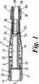
【図1】供給されたままの状態の、発射機構を取りつけていない注射装置の軸を含む断面である。
【図2】発射機構を取りつけて使用の準備が整った装置の軸を含む断面である。
【図3】注射装置の部分の詳細斜視図である。
【図4】発射機構を取りつけた注射中の装置の、軸を含む断面である。
【図5】発射機構を取りつけたままの、使用後の装置の軸を含む断面である。
【図6】注射装置セットのためのハウジングの切り欠き斜視図である。
【符号の説明】
【0031】
1 バレル
4 コネクター
6 発射機構
8 プランジャー
13 注射器
14 針
16 キャリヤー
22 戻りばね
24 ガイド
31 ケース
32 定置具
35 キャップ[0001]
The present invention relates to an injection device.
[0002]
FR-A-2654948 discloses an injection device comprising a barrel, a syringe carrier in the barrel, a spring means, and a firing mechanism, wherein the syringe carrier is held by the carrier and includes a syringe needle. An axially movable between a rear position retracted into the front end of the barrel and a front position where the needle protrudes from the front end of the barrel, and the spring means directs the carrier to the rear position Press In the injection device in which the firing mechanism has a firing member, and when the member is released, the member acts on a piston in the syringe to push the syringe forward, and then ejects the administration drug. An injection device is disclosed that can be separated from the barrel.
[0003]
After injection, the needled syringe is discarded in a guarded container for safety. However, removing the syringe from a reusable device that first fires the syringe forward to penetrate the needle, then pushes the syringe piston forward to eject the dose, and finally retracts the syringe and needle is It is dangerous and time consuming.
[0004]
One answer is to discard everything, but such injection devices are complex and expensive. This is therefore not a practical choice.
[0005]
However, the device is manufactured in two parts, one part being a reusable firing mechanism with a plunger that can be released and springed forward, the other part being a firing mechanism. The housing and guide for the syringe, which can be temporarily mounted, allows the latter part to be discarded (while the syringe is housed).
[0006]
The object of the present invention is to provide such an apparatus.
[0007]
In accordance with the present invention, an injection device comprising a barrel, a syringe carrier within the barrel, a spring means, and a firing mechanism, wherein the syringe carrier is held by the carrier with a syringe needle within the front end of the barrel. Between the rear position retracted into the front position and the front position in which the needle protrudes from the front end of the barrel, the spring means pushes the carrier toward the rear position, In an injection device, wherein the firing mechanism has a firing member, and when the member is released, the member acts on a piston in the syringe to push the syringe forward, and then to eject the dose, the firing mechanism is There is a connector that can be separated from the barrel and has a limited degree of axial movement at the rear end of the barrel for attachment of the firing mechanism. The connector is initially held in the rearward position by spring means acting through the syringe carrier, but when the barrel is held against the skin, it holds the syringe carrier when pushed forward by the firing mechanism. Moved to the forward position, when the syringe carrier is in an intermediate position, from which it can be pushed to the forward position by the action of the firing mechanism, after the connector has released the injection device from the skin An injection device is provided, characterized in that it returns to a rearward position under the action of a spring means.
[0008]
The spring means acts through the carrier, syringe, firing member and its device to return the connector to the rearward position.
[0009]
Conveniently, the attachment is by a mating screw and the connector is held against rotation with respect to the barrel.
[0010]
The connector may be a stepped tube, a small diameter portion at the rear end provides a socket for receiving the firing mechanism, and an internal front facing shoulder formed by the step is the rear end of the syringe carrier And when the connector is in the rear position, the outer rear facing shoulder formed by the step has a contact portion for engaging with a fixing ring fitted to the rear end of the barrel. Can be given.
[0011]
The syringe carrier can have a swivel connection to the connector, which can limit the forward movement of the carrier. The large diameter portion of the stepped tube connector can have a slot parallel to the axis that engages a protrusion from the rear end of the syringe carrier to form a movement connection. be able to.
[0012]
The barrel can generally be provided with guide means therein for holding the syringe carrier coaxial with the barrel.
[0013]
The spring means is conveniently a coil spring that surrounds the syringe carrier, which engages a flange at the rear end of the carrier and reacts against a contact in the barrel. This contact portion can be provided by the rear end of the guide means.
[0014]
Preferably, the front end of the barrel is provided with means for effectively changing the length of the front end, and thus the length from which the syringe needle protrudes.
[0015]
In order that the present invention may be more fully understood, one embodiment will now be described by way of example with reference to the accompanying drawings.
[0016]
The injection device has a barrel 1 which has a tapered
[0017]
Within the barrel 1 is a syringe consisting of a
[0018]
A
[0019]
In the initial state, the
[0020]
In use, the firing mechanism 6 is screwed into the
[0021]
The injection device is then applied to the user's skin and the firing device 6 is pushed forward. This causes the tube 4 to move forward and further into the rear part 3 of the barrel 1. Since the barrel 1 is of course applied to the patient, it is stationary. This movement continues until the connector 4 stops. This stop is conveniently caused by the
[0022]
The button 7 is then pressed and the plunger 8 is fired forward to engage a piston (not shown) in the capsule, first the capsule is ejected forward with its
[0023]
Finally, when the injection device is pulled apart, the
[0024]
The firing mechanism 6 is then separated from the injection device, the latter can be discarded and the firing mechanism can be reused.
[0025]
The
[0026]
When using the device, the
[0029]
After use, the injection device is replaced and rotated by the firing mechanism 6 and screwed into the
[Brief description of the drawings]
[0030]
FIG. 1 is a cross-section including the shaft of an injection device with no firing mechanism, as delivered.
FIG. 2 is a cross-section including the axis of the device with the firing mechanism installed and ready for use.
FIG. 3 is a detailed perspective view of a portion of the injection device.
FIG. 4 is a cross-section including the shaft of the device during injection with the firing mechanism attached.
FIG. 5 is a cross section including the axis of the device after use, with the firing mechanism attached.
6 is a cutaway perspective view of a housing for an injection device set. FIG.
[Explanation of symbols]
[0031]
1 Barrel 4 Connector 6 Firing mechanism 8
Claims (9)
Applications Claiming Priority (3)
| Application Number | Priority Date | Filing Date | Title |
|---|---|---|---|
| GBGB9716065.9A GB9716065D0 (en) | 1997-07-31 | 1997-07-31 | Improvements relating to injection devices |
| GB9716065.9 | 1997-07-31 | ||
| PCT/GB1998/002287 WO1999006100A2 (en) | 1997-07-31 | 1998-07-30 | Improvements relating to injection devices |
Publications (2)
| Publication Number | Publication Date |
|---|---|
| JP2001511404A JP2001511404A (en) | 2001-08-14 |
| JP4049994B2 true JP4049994B2 (en) | 2008-02-20 |
Family
ID=10816687
Family Applications (1)
| Application Number | Title | Priority Date | Filing Date |
|---|---|---|---|
| JP2000504909A Expired - Lifetime JP4049994B2 (en) | 1997-07-31 | 1998-07-30 | Improvements regarding injection devices |
Country Status (13)
| Country | Link |
|---|---|
| US (1) | US6692469B1 (en) |
| EP (2) | EP1334739B1 (en) |
| JP (1) | JP4049994B2 (en) |
| AT (2) | ATE260127T1 (en) |
| AU (1) | AU736632B2 (en) |
| CA (1) | CA2298472C (en) |
| DE (2) | DE69839283T2 (en) |
| DK (1) | DK0999864T3 (en) |
| ES (2) | ES2301727T3 (en) |
| GB (1) | GB9716065D0 (en) |
| IL (3) | IL134284A (en) |
| PT (1) | PT999864E (en) |
| WO (1) | WO1999006100A2 (en) |
Families Citing this family (99)
| Publication number | Priority date | Publication date | Assignee | Title |
|---|---|---|---|---|
| AU5614199A (en) * | 1999-04-14 | 2000-11-14 | Thomas Randall Inkpen | Needle injection-facilitating device |
| GB0008955D0 (en) * | 2000-04-12 | 2000-05-31 | Owen Mumford Ltd | An injector pack |
| GB0109001D0 (en) * | 2001-04-10 | 2001-05-30 | Glaxo Group Ltd | Dispenser |
| US7235063B2 (en) * | 2001-08-21 | 2007-06-26 | D'antonio Consultants International, Inc. | Hypodermic injection system |
| US7081148B2 (en) | 2001-09-18 | 2006-07-25 | Praxair S.T. Technology, Inc. | Textured-grain-powder metallurgy tantalum sputter target |
| EP1441787B2 (en) | 2001-11-09 | 2014-02-26 | ALZA Corporation | Pneumatic powered autoinjector |
| JP2005516646A (en) | 2001-11-09 | 2005-06-09 | アルザ・コーポレーシヨン | Syringe cartridge related case that can be dented |
| US7252651B2 (en) * | 2003-01-07 | 2007-08-07 | Becton, Dickinson And Company | Disposable injection device |
| AU2003303809A1 (en) * | 2003-01-24 | 2004-08-23 | Alza Corporation | Collapsible syringe cartridge |
| GB2414404B (en) | 2004-05-28 | 2009-06-03 | Cilag Ag Int | Injection device |
| GB2414775B (en) * | 2004-05-28 | 2008-05-21 | Cilag Ag Int | Releasable coupling and injection device |
| GB2414401B (en) | 2004-05-28 | 2009-06-17 | Cilag Ag Int | Injection device |
| GB2414403B (en) * | 2004-05-28 | 2009-01-07 | Cilag Ag Int | Injection device |
| GB2414405B (en) * | 2004-05-28 | 2009-01-14 | Cilag Ag Int | Injection device |
| GB2414402B (en) * | 2004-05-28 | 2009-04-22 | Cilag Ag Int | Injection device |
| GB2414400B (en) * | 2004-05-28 | 2009-01-14 | Cilag Ag Int | Injection device |
| GB2414406B (en) † | 2004-05-28 | 2009-03-18 | Cilag Ag Int | Injection device |
| GB2414409B (en) * | 2004-05-28 | 2009-11-18 | Cilag Ag Int | Injection device |
| GB2414399B (en) * | 2004-05-28 | 2008-12-31 | Cilag Ag Int | Injection device |
| GB0414054D0 (en) | 2004-06-23 | 2004-07-28 | Owen Mumford Ltd | Improvements relating to automatic injection devices |
| US7947017B2 (en) | 2004-11-22 | 2011-05-24 | Intelliject, Inc. | Devices, systems and methods for medicament delivery |
| US10737028B2 (en) | 2004-11-22 | 2020-08-11 | Kaleo, Inc. | Devices, systems and methods for medicament delivery |
| US7648482B2 (en) | 2004-11-22 | 2010-01-19 | Intelliject, Inc. | Devices, systems, and methods for medicament delivery |
| US11590286B2 (en) | 2004-11-22 | 2023-02-28 | Kaleo, Inc. | Devices, systems and methods for medicament delivery |
| US7648483B2 (en) | 2004-11-22 | 2010-01-19 | Intelliject, Inc. | Devices, systems and methods for medicament delivery |
| JP4960252B2 (en) | 2004-11-22 | 2012-06-27 | インテリジェクト,インコーポレイテッド | Device, system and method for drug delivery |
| ES2396745T3 (en) | 2005-02-01 | 2013-02-25 | Intelliject, Inc. | Devices for medication administration |
| GB2425062B (en) * | 2005-04-06 | 2010-07-21 | Cilag Ag Int | Injection device |
| GB2424837B (en) * | 2005-04-06 | 2010-10-06 | Cilag Ag Int | Injection device |
| GB2424836B (en) * | 2005-04-06 | 2010-09-22 | Cilag Ag Int | Injection device (bayonet cap removal) |
| GB2424838B (en) * | 2005-04-06 | 2011-02-23 | Cilag Ag Int | Injection device (adaptable drive) |
| GB2424835B (en) * | 2005-04-06 | 2010-06-09 | Cilag Ag Int | Injection device (modified trigger) |
| GB2427826B (en) | 2005-04-06 | 2010-08-25 | Cilag Ag Int | Injection device comprising a locking mechanism associated with integrally formed biasing means |
| FR2884721A1 (en) * | 2005-04-20 | 2006-10-27 | Becton Dickinson France Soc Pa | Assistance device for device of injection of a product, comprises hollow body for receiving the product, hollow injection needle for penetrating into injection site, piston placed in the body, hollow sleeve with bearing surface |
| US20070055199A1 (en) | 2005-08-10 | 2007-03-08 | Gilbert Scott J | Drug delivery device for buccal and aural applications and other areas of the body difficult to access |
| DE602005018480D1 (en) | 2005-08-30 | 2010-02-04 | Cilag Gmbh Int | Needle device for a prefilled syringe |
| US20110098656A1 (en) * | 2005-09-27 | 2011-04-28 | Burnell Rosie L | Auto-injection device with needle protecting cap having outer and inner sleeves |
| GB0524604D0 (en) | 2005-12-02 | 2006-01-11 | Owen Mumford Ltd | Injection method and apparatus |
| DE102006006796A1 (en) * | 2006-02-14 | 2007-08-16 | Tecpharma Licensing Ag | Overlapping display |
| US7811252B2 (en) | 2006-05-17 | 2010-10-12 | Alcon Research, Ltd. | Dosage control device |
| GB2438591B (en) * | 2006-06-01 | 2011-07-13 | Cilag Gmbh Int | Injection device |
| GB2438593B (en) | 2006-06-01 | 2011-03-30 | Cilag Gmbh Int | Injection device (cap removal feature) |
| GB2438590B (en) | 2006-06-01 | 2011-02-09 | Cilag Gmbh Int | Injection device |
| CA2651992A1 (en) * | 2006-06-30 | 2008-01-10 | Abbott Biotechnology Ltd. | Automatic injection device |
| FR2905273B1 (en) * | 2006-09-06 | 2009-04-03 | Becton Dickinson France Soc Pa | AUTOMATIC INJECTION DEVICE WITH TIMING MEANS. |
| DE102007054868A1 (en) * | 2007-11-07 | 2009-05-20 | Arzneimittel Gmbh Apotheker Vetter & Co. Ravensburg | Device and method for mounting a pharmaceutical application aid |
| US8177749B2 (en) | 2008-05-20 | 2012-05-15 | Avant Medical Corp. | Cassette for a hidden injection needle |
| MX2010012691A (en) | 2008-05-20 | 2011-03-30 | Avant Medical Corp Star | Autoinjector system. |
| US8052645B2 (en) * | 2008-07-23 | 2011-11-08 | Avant Medical Corp. | System and method for an injection using a syringe needle |
| GB2461086B (en) * | 2008-06-19 | 2012-12-05 | Cilag Gmbh Int | Injection device |
| GB2461084B (en) * | 2008-06-19 | 2012-09-26 | Cilag Gmbh Int | Fluid transfer assembly |
| GB2461087B (en) * | 2008-06-19 | 2012-09-26 | Cilag Gmbh Int | Injection device |
| GB2461088B (en) * | 2008-06-19 | 2012-09-26 | Cilag Gmbh Int | Injection device |
| GB2461089B (en) * | 2008-06-19 | 2012-09-19 | Cilag Gmbh Int | Injection device |
| GB2461085B (en) | 2008-06-19 | 2012-08-29 | Cilag Gmbh Int | Injection device |
| GB2463071A (en) * | 2008-09-02 | 2010-03-03 | Owen Mumford Ltd | Auto-injector syringe with safety shield |
| GB0823693D0 (en) * | 2008-12-31 | 2009-02-04 | Owen Mumford Ltd | Autoinjector |
| GB0900930D0 (en) * | 2009-01-20 | 2009-03-04 | Future Injection Technologies Ltd | Injection device |
| EP2401009B1 (en) | 2009-02-26 | 2012-11-28 | Tecpharma Licensing AG | Product container holder for an injection device and for receiving a product container |
| MX2011009168A (en) | 2009-03-13 | 2011-09-15 | Lilly Co Eli | Apparatus for injecting a pharmaceutical with automatic syringe retraction following injection. |
| BRPI1012162A2 (en) | 2009-04-29 | 2016-01-12 | Abbott Biotech Ltd | automatic injection device |
| TWI619521B (en) * | 2009-12-15 | 2018-04-01 | 艾伯維生物技術有限責任公司 | Automatic injection device, automatic injection method and method for preventing misfiring |
| KR101850687B1 (en) | 2010-04-21 | 2018-04-20 | 애브비 바이오테크놀로지 리미티드 | Wearable automatic injection device for controlled delivery of therapeutic agents |
| US8196741B2 (en) | 2010-09-30 | 2012-06-12 | Tyco Healthcare Group Lp | Syringe assembly and package for distribution of same |
| US8286791B2 (en) * | 2010-09-30 | 2012-10-16 | Tyco Healthcare Group Lp | Syringe assembly carrier |
| EP2468338A1 (en) | 2010-12-21 | 2012-06-27 | Sanofi-Aventis Deutschland GmbH | Auto-injector |
| EP3473283B1 (en) | 2011-01-24 | 2020-12-09 | AbbVie Biotechnology Ltd. | Removal of needle shields from syringes and automatic injection devices |
| EP3187216B1 (en) | 2011-01-24 | 2019-08-21 | AbbVie Biotechnology Ltd. | Automatic injection devices having overmolded gripping surfaces |
| AU2012210170B2 (en) | 2011-01-24 | 2016-09-29 | Elcam Medical Agricultural Cooperative Association Ltd. | Injector |
| US9084849B2 (en) | 2011-01-26 | 2015-07-21 | Kaleo, Inc. | Medicament delivery devices for administration of a medicament within a prefilled syringe |
| US8939943B2 (en) | 2011-01-26 | 2015-01-27 | Kaleo, Inc. | Medicament delivery device for administration of opioid antagonists including formulations for naloxone |
| BR112013023967A2 (en) * | 2011-03-18 | 2016-01-19 | Abbvie Inc | systems, devices and methods for assembling automatic injection devices and subsets thereof |
| US10092706B2 (en) | 2011-04-20 | 2018-10-09 | Amgen Inc. | Autoinjector apparatus |
| WO2012170700A2 (en) | 2011-06-07 | 2012-12-13 | Orthocon, Inc. | Applicator with conformable tip |
| AU2012335825B2 (en) | 2011-11-07 | 2017-02-16 | Safety Syringes, Inc. | Contact trigger release needle guard |
| USD898908S1 (en) | 2012-04-20 | 2020-10-13 | Amgen Inc. | Pharmaceutical product cassette for an injection device |
| USD808010S1 (en) | 2012-04-20 | 2018-01-16 | Amgen Inc. | Injection device |
| EP2656865A1 (en) * | 2012-04-24 | 2013-10-30 | Sanofi-Aventis Deutschland GmbH | Syringe carrier with needle shield and data storage device for use in a medical auto-injection device |
| AU2012101225B4 (en) * | 2012-08-13 | 2013-10-10 | Caretech Services Pty Ltd | Syringe safety device and method of syringe disposal |
| US9943641B2 (en) * | 2013-03-14 | 2018-04-17 | Becton, Dickinson And Company | Package for medical product |
| US10092703B2 (en) | 2013-03-15 | 2018-10-09 | Amgen Inc. | Drug cassette, autoinjector, and autoinjector system |
| EP3593839A1 (en) | 2013-03-15 | 2020-01-15 | Amgen Inc. | Drug cassette |
| GB2515032A (en) | 2013-06-11 | 2014-12-17 | Cilag Gmbh Int | Guide for an injection device |
| GB2515038A (en) | 2013-06-11 | 2014-12-17 | Cilag Gmbh Int | Injection device |
| GB2517896B (en) | 2013-06-11 | 2015-07-08 | Cilag Gmbh Int | Injection device |
| GB2515039B (en) | 2013-06-11 | 2015-05-27 | Cilag Gmbh Int | Injection Device |
| US10751470B2 (en) | 2014-02-10 | 2020-08-25 | E3D A.C.A.L Ltd | Semi disposable auto injector |
| US9517307B2 (en) | 2014-07-18 | 2016-12-13 | Kaleo, Inc. | Devices and methods for delivering opioid antagonists including formulations for naloxone |
| CN106573113B (en) | 2014-08-15 | 2020-04-17 | 伊莱利利公司 | Automatic medicament injection device with visual indication of injection progress |
| CA3009221A1 (en) | 2014-12-23 | 2016-06-30 | Automed Pty Ltd | Delivery apparatus, system and associated methods |
| WO2017004345A1 (en) | 2015-06-30 | 2017-01-05 | Kaleo, Inc. | Auto-injectors for administration of a medicament within a prefilled syringe |
| EP3834865A3 (en) | 2015-08-27 | 2021-12-29 | E3D Agricultural Cooperative Association Ltd. | Reusable automatic injection device |
| US11065381B2 (en) | 2015-10-05 | 2021-07-20 | E3D A.C.A.L. | Infusion pump device and method for use thereof |
| GB2556091A (en) * | 2016-11-18 | 2018-05-23 | Owen Mumford Ltd | Medicament delivery device and system |
| JP7014797B2 (en) | 2016-12-23 | 2022-02-01 | カレオ,インコーポレイテッド | Drug delivery devices and methods for delivering drugs to babies and children |
| EP3697468A1 (en) | 2017-10-20 | 2020-08-26 | West Pharmaceutical Services, Inc. | Semi-reusable palm activated injector system |
| EP4009936A4 (en) | 2019-08-09 | 2023-08-09 | Kaleo, Inc. | Devices and methods for delivery of substances within a prefilled syringe |
| CN110663672A (en) * | 2019-11-13 | 2020-01-10 | 南京林业大学 | Root pesticide application head driven by screw thread |
| WO2021146356A1 (en) * | 2020-01-13 | 2021-07-22 | DJ Medical, LLC | Injection device, system, and method for use |
Family Cites Families (14)
| Publication number | Priority date | Publication date | Assignee | Title |
|---|---|---|---|---|
| US3292776A (en) * | 1964-11-12 | 1966-12-20 | Thomas R Penn | Hypodermic storage kit |
| GB8705284D0 (en) | 1987-03-06 | 1987-04-08 | Secr Defence | Hypodermic needle apparatus |
| NL8700947A (en) * | 1987-04-21 | 1988-11-16 | Medicopharma Nv | DISPOSABLE INJECTION SYRINGE. |
| FR2623403B1 (en) | 1987-11-20 | 1990-03-30 | Bacci Louis | PROCESS AND DEVICE FOR PLACING AND DEPOSITING SYRINGE NEEDLES, WITHOUT MANUAL CONTACT |
| GB8926825D0 (en) * | 1989-11-28 | 1990-01-17 | Glaxo Group Ltd | Device |
| US5092376A (en) * | 1990-12-24 | 1992-03-03 | Mcdonnell Douglas Corporation | Apparatus for injecting resin |
| US5451210A (en) * | 1991-04-29 | 1995-09-19 | Lifequest Medical, Inc. | System and method for rapid vascular drug delivery |
| US5167641A (en) * | 1991-05-29 | 1992-12-01 | Arnis, Inc. | Auto-retracting needle injector system |
| US5695472A (en) | 1993-05-27 | 1997-12-09 | Washington Biotech Corporation | Modular automatic or manual emergency medicine injection system |
| US5478316A (en) | 1994-02-02 | 1995-12-26 | Becton, Dickinson And Company | Automatic self-injection device |
| US5718239A (en) * | 1996-06-21 | 1998-02-17 | Becton, Dickinson And Company | Method of activating a needle assembly having a telescoping shield |
| US5709662A (en) * | 1996-08-23 | 1998-01-20 | Becton Dickinson France, S.A. | Cartridge for an injection device |
| AUPO889497A0 (en) * | 1997-09-01 | 1997-09-25 | N.J. Phillips Pty. Limited | An applicator |
| US6391003B1 (en) * | 1999-10-25 | 2002-05-21 | Antares Pharma, Inc. | Locking mechanism for a jet injector |
-
1997
- 1997-07-31 GB GBGB9716065.9A patent/GB9716065D0/en active Pending
-
1998
- 1998-07-30 EP EP03011335A patent/EP1334739B1/en not_active Expired - Lifetime
- 1998-07-30 ES ES03011335T patent/ES2301727T3/en not_active Expired - Lifetime
- 1998-07-30 JP JP2000504909A patent/JP4049994B2/en not_active Expired - Lifetime
- 1998-07-30 AT AT98936554T patent/ATE260127T1/en active
- 1998-07-30 WO PCT/GB1998/002287 patent/WO1999006100A2/en active IP Right Grant
- 1998-07-30 IL IL13428498A patent/IL134284A/en not_active IP Right Cessation
- 1998-07-30 US US09/463,748 patent/US6692469B1/en not_active Expired - Lifetime
- 1998-07-30 ES ES98936554T patent/ES2212325T3/en not_active Expired - Lifetime
- 1998-07-30 DE DE69839283T patent/DE69839283T2/en not_active Expired - Lifetime
- 1998-07-30 AU AU85518/98A patent/AU736632B2/en not_active Expired
- 1998-07-30 DE DE69821943T patent/DE69821943T2/en not_active Expired - Lifetime
- 1998-07-30 EP EP98936554A patent/EP0999864B1/en not_active Expired - Lifetime
- 1998-07-30 CA CA002298472A patent/CA2298472C/en not_active Expired - Lifetime
- 1998-07-30 IL IL15657998A patent/IL156579A0/en unknown
- 1998-07-30 PT PT98936554T patent/PT999864E/en unknown
- 1998-07-30 AT AT03011335T patent/ATE389428T1/en not_active IP Right Cessation
- 1998-07-30 DK DK98936554T patent/DK0999864T3/en active
-
2003
- 2003-06-22 IL IL156579A patent/IL156579A/en not_active IP Right Cessation
Also Published As
| Publication number | Publication date |
|---|---|
| EP0999864B1 (en) | 2004-02-25 |
| IL156579A (en) | 2009-12-24 |
| CA2298472A1 (en) | 1999-02-11 |
| AU8551898A (en) | 1999-02-22 |
| DK0999864T3 (en) | 2004-04-13 |
| DE69839283D1 (en) | 2008-04-30 |
| JP2001511404A (en) | 2001-08-14 |
| PT999864E (en) | 2004-05-31 |
| IL156579A0 (en) | 2004-01-04 |
| DE69821943T2 (en) | 2004-07-15 |
| DE69821943D1 (en) | 2004-04-01 |
| WO1999006100A2 (en) | 1999-02-11 |
| CA2298472C (en) | 2007-05-22 |
| ATE260127T1 (en) | 2004-03-15 |
| GB9716065D0 (en) | 1997-10-01 |
| ES2212325T3 (en) | 2004-07-16 |
| EP0999864A2 (en) | 2000-05-17 |
| EP1334739B1 (en) | 2008-03-19 |
| WO1999006100A3 (en) | 1999-04-08 |
| IL134284A0 (en) | 2001-04-30 |
| DE69839283T2 (en) | 2009-04-02 |
| IL134284A (en) | 2004-09-27 |
| US6692469B1 (en) | 2004-02-17 |
| EP1334739A2 (en) | 2003-08-13 |
| EP1334739A3 (en) | 2003-09-10 |
| ES2301727T3 (en) | 2008-07-01 |
| AU736632B2 (en) | 2001-08-02 |
| ATE389428T1 (en) | 2008-04-15 |
Similar Documents
| Publication | Publication Date | Title |
|---|---|---|
| JP4049994B2 (en) | Improvements regarding injection devices | |
| JP4162377B2 (en) | Improvements regarding injection devices | |
| US5433712A (en) | Self-sheathing hypodermic syringe | |
| JP4219979B2 (en) | Improvements related to medical injection devices | |
| EP1216719B1 (en) | Safety syringe | |
| JP4358619B2 (en) | Injection device | |
| AU2004286735B2 (en) | Autoinjection device | |
| AU565377B2 (en) | Dual mode automatic injector | |
| JP2002502672A (en) | Improvements on medical injection devices | |
| CN1288391A (en) | Disposable safety syringe | |
| JP4611300B2 (en) | Syringe actuator and storage device | |
| GB1449986A (en) | Hypodermic syringe | |
| US7135031B2 (en) | Repeated use trocar-needle insertion instrument and loading tool | |
| CA2468683A1 (en) | Safety syringe with re-usable main parts, method for disposal of a needle into a container and container for disposable parts | |
| EP1237600B1 (en) | Improvements in or relating to hypodermic syringes | |
| US6423033B1 (en) | Safety hypodermic syringe | |
| JPH0673823B2 (en) | Gunpowder-powered driving device | |
| CN117258075A (en) | Device for dispensing a fluid | |
| JP2022079428A (en) | System and method for needle hiding in injectors | |
| MXPA96003932A (en) | Hydrothermic safety syringe of doses pequ |
Legal Events
| Date | Code | Title | Description |
|---|---|---|---|
| A621 | Written request for application examination |
Free format text: JAPANESE INTERMEDIATE CODE: A621 Effective date: 20050427 |
|
| RD02 | Notification of acceptance of power of attorney |
Free format text: JAPANESE INTERMEDIATE CODE: A7422 Effective date: 20070706 |
|
| A131 | Notification of reasons for refusal |
Free format text: JAPANESE INTERMEDIATE CODE: A131 Effective date: 20070710 |
|
| A521 | Request for written amendment filed |
Free format text: JAPANESE INTERMEDIATE CODE: A523 Effective date: 20071009 |
|
| TRDD | Decision of grant or rejection written | ||
| A01 | Written decision to grant a patent or to grant a registration (utility model) |
Free format text: JAPANESE INTERMEDIATE CODE: A01 Effective date: 20071106 |
|
| A61 | First payment of annual fees (during grant procedure) |
Free format text: JAPANESE INTERMEDIATE CODE: A61 Effective date: 20071128 |
|
| R150 | Certificate of patent or registration of utility model |
Free format text: JAPANESE INTERMEDIATE CODE: R150 |
|
| FPAY | Renewal fee payment (event date is renewal date of database) |
Free format text: PAYMENT UNTIL: 20101207 Year of fee payment: 3 |
|
| FPAY | Renewal fee payment (event date is renewal date of database) |
Free format text: PAYMENT UNTIL: 20101207 Year of fee payment: 3 |
|
| FPAY | Renewal fee payment (event date is renewal date of database) |
Free format text: PAYMENT UNTIL: 20111207 Year of fee payment: 4 |
|
| FPAY | Renewal fee payment (event date is renewal date of database) |
Free format text: PAYMENT UNTIL: 20111207 Year of fee payment: 4 |
|
| FPAY | Renewal fee payment (event date is renewal date of database) |
Free format text: PAYMENT UNTIL: 20121207 Year of fee payment: 5 |
|
| FPAY | Renewal fee payment (event date is renewal date of database) |
Free format text: PAYMENT UNTIL: 20121207 Year of fee payment: 5 |
|
| FPAY | Renewal fee payment (event date is renewal date of database) |
Free format text: PAYMENT UNTIL: 20131207 Year of fee payment: 6 |
|
| R250 | Receipt of annual fees |
Free format text: JAPANESE INTERMEDIATE CODE: R250 |
|
| R250 | Receipt of annual fees |
Free format text: JAPANESE INTERMEDIATE CODE: R250 |
|
| R250 | Receipt of annual fees |
Free format text: JAPANESE INTERMEDIATE CODE: R250 |
|
| R250 | Receipt of annual fees |
Free format text: JAPANESE INTERMEDIATE CODE: R250 |
|
| R250 | Receipt of annual fees |
Free format text: JAPANESE INTERMEDIATE CODE: R250 |
|
| EXPY | Cancellation because of completion of term |