JP4045253B2 - Capillary and electrophoresis device - Google Patents
Capillary and electrophoresis device Download PDFInfo
- Publication number
- JP4045253B2 JP4045253B2 JP2004088305A JP2004088305A JP4045253B2 JP 4045253 B2 JP4045253 B2 JP 4045253B2 JP 2004088305 A JP2004088305 A JP 2004088305A JP 2004088305 A JP2004088305 A JP 2004088305A JP 4045253 B2 JP4045253 B2 JP 4045253B2
- Authority
- JP
- Japan
- Prior art keywords
- capillary
- lens
- electrophoresis apparatus
- capillaries
- fluorescence
- Prior art date
- Legal status (The legal status is an assumption and is not a legal conclusion. Google has not performed a legal analysis and makes no representation as to the accuracy of the status listed.)
- Expired - Lifetime
Links
- 238000001962 electrophoresis Methods 0.000 title claims description 22
- 239000011521 glass Substances 0.000 claims description 46
- 239000007788 liquid Substances 0.000 claims description 31
- 238000000926 separation method Methods 0.000 claims description 25
- 238000005251 capillar electrophoresis Methods 0.000 claims description 23
- 239000011248 coating agent Substances 0.000 claims description 18
- 238000000576 coating method Methods 0.000 claims description 18
- 229920000642 polymer Polymers 0.000 claims description 10
- 238000003491 array Methods 0.000 claims description 4
- 230000001678 irradiating effect Effects 0.000 claims description 2
- 238000001514 detection method Methods 0.000 description 56
- 230000035945 sensitivity Effects 0.000 description 10
- 230000003287 optical effect Effects 0.000 description 9
- 230000005284 excitation Effects 0.000 description 7
- 239000004809 Teflon Substances 0.000 description 6
- 229920006362 Teflon® Polymers 0.000 description 6
- 238000004458 analytical method Methods 0.000 description 6
- 238000001917 fluorescence detection Methods 0.000 description 6
- 238000001712 DNA sequencing Methods 0.000 description 5
- VYPSYNLAJGMNEJ-UHFFFAOYSA-N Silicium dioxide Chemical compound O=[Si]=O VYPSYNLAJGMNEJ-UHFFFAOYSA-N 0.000 description 5
- 239000007853 buffer solution Substances 0.000 description 5
- 230000007423 decrease Effects 0.000 description 5
- 230000000694 effects Effects 0.000 description 5
- 230000005684 electric field Effects 0.000 description 5
- 230000014509 gene expression Effects 0.000 description 5
- 239000000758 substrate Substances 0.000 description 5
- 238000003384 imaging method Methods 0.000 description 4
- 239000000463 material Substances 0.000 description 4
- 238000000034 method Methods 0.000 description 4
- 230000005012 migration Effects 0.000 description 4
- 238000013508 migration Methods 0.000 description 4
- 101001122597 Homo sapiens Ribonuclease P protein subunit p20 Proteins 0.000 description 3
- 102100028674 Ribonuclease P protein subunit p20 Human genes 0.000 description 3
- 230000008859 change Effects 0.000 description 3
- 238000012163 sequencing technique Methods 0.000 description 3
- 239000004925 Acrylic resin Substances 0.000 description 2
- 229920000178 Acrylic resin Polymers 0.000 description 2
- 239000000872 buffer Substances 0.000 description 2
- 238000001816 cooling Methods 0.000 description 2
- 238000004519 manufacturing process Methods 0.000 description 2
- 230000005855 radiation Effects 0.000 description 2
- 238000005070 sampling Methods 0.000 description 2
- 239000000243 solution Substances 0.000 description 2
- NAWXUBYGYWOOIX-SFHVURJKSA-N (2s)-2-[[4-[2-(2,4-diaminoquinazolin-6-yl)ethyl]benzoyl]amino]-4-methylidenepentanedioic acid Chemical compound C1=CC2=NC(N)=NC(N)=C2C=C1CCC1=CC=C(C(=O)N[C@@H](CC(=C)C(O)=O)C(O)=O)C=C1 NAWXUBYGYWOOIX-SFHVURJKSA-N 0.000 description 1
- 230000004075 alteration Effects 0.000 description 1
- 239000012491 analyte Substances 0.000 description 1
- XKRFYHLGVUSROY-UHFFFAOYSA-N argon Substances [Ar] XKRFYHLGVUSROY-UHFFFAOYSA-N 0.000 description 1
- 229910052786 argon Inorganic materials 0.000 description 1
- -1 argon ion Chemical class 0.000 description 1
- 230000008901 benefit Effects 0.000 description 1
- 230000005540 biological transmission Effects 0.000 description 1
- 238000004364 calculation method Methods 0.000 description 1
- 239000007795 chemical reaction product Substances 0.000 description 1
- 230000003247 decreasing effect Effects 0.000 description 1
- 238000010586 diagram Methods 0.000 description 1
- 238000005516 engineering process Methods 0.000 description 1
- 239000012530 fluid Substances 0.000 description 1
- 238000002073 fluorescence micrograph Methods 0.000 description 1
- 239000007850 fluorescent dye Substances 0.000 description 1
- 229920002313 fluoropolymer Polymers 0.000 description 1
- 239000004811 fluoropolymer Substances 0.000 description 1
- 230000004907 flux Effects 0.000 description 1
- 230000010354 integration Effects 0.000 description 1
- 238000005259 measurement Methods 0.000 description 1
- 239000004033 plastic Substances 0.000 description 1
- 239000000047 product Substances 0.000 description 1
- 102000004169 proteins and genes Human genes 0.000 description 1
- 108090000623 proteins and genes Proteins 0.000 description 1
- 230000009467 reduction Effects 0.000 description 1
- 239000000126 substance Substances 0.000 description 1
- 239000012780 transparent material Substances 0.000 description 1
- 239000002699 waste material Substances 0.000 description 1
Images


Classifications
-
- G—PHYSICS
- G01—MEASURING; TESTING
- G01N—INVESTIGATING OR ANALYSING MATERIALS BY DETERMINING THEIR CHEMICAL OR PHYSICAL PROPERTIES
- G01N27/00—Investigating or analysing materials by the use of electric, electrochemical, or magnetic means
- G01N27/26—Investigating or analysing materials by the use of electric, electrochemical, or magnetic means by investigating electrochemical variables; by using electrolysis or electrophoresis
- G01N27/416—Systems
- G01N27/447—Systems using electrophoresis
- G01N27/44704—Details; Accessories
- G01N27/44717—Arrangements for investigating the separated zones, e.g. localising zones
- G01N27/44721—Arrangements for investigating the separated zones, e.g. localising zones by optical means
Description
本発明は、蛍光標識されたDNA,RNAや蛋白などの試料を電気泳動により分離し,レーザー励起蛍光検出することにより,DNAの塩基配列,塩基長など、試料を分析するキャピラリー及び電気泳動装置に関する。 The present invention relates to a capillary and an electrophoresis apparatus for analyzing a sample such as a DNA base sequence and a base length by separating a sample of fluorescently labeled DNA, RNA, protein or the like by electrophoresis and detecting the laser excitation fluorescence. .
従来から、蛍光標識されたDNAなどの試料を電気泳動によって分子量分離し、試料にレーザを照射して蛍光標識から発する蛍光を検出し、検出される一連の信号を解析する、いわゆる電気泳動装置が用いられている。
蛍光の検出には、様々な方法があるが、特開平9―96623号(特許文献1)では,キャピラリー中を電気泳動するDNAにレーザビームを照射し,DNAから放射された蛍光を試料の泳動方向に直交する方向から検出している。本願明細書では、このように、試料の泳動方向に対して直交する方向から検出する蛍光検出方法を、「直交検出」と呼ぶ。
Conventionally, there is a so-called electrophoresis device that separates the molecular weight of a sample such as fluorescently labeled DNA by electrophoresis, detects the fluorescence emitted from the fluorescent label by irradiating the sample with a laser, and analyzes a series of detected signals. It is used.
There are various methods for detecting fluorescence. In JP-A-9-96623 (Patent Document 1), DNA to be electrophoresed in a capillary is irradiated with a laser beam, and the fluorescence emitted from the DNA is migrated to the sample. Detecting from a direction orthogonal to the direction. In this specification, the fluorescence detection method in which detection is performed from a direction orthogonal to the migration direction of the sample is referred to as “orthogonal detection”.
一方、特開平8―261988号(特許文献2)では,泳動板中を電気泳動するDNAにレーザビームを照射し,DNAから放射された蛍光をDNAが泳動する方向から検出している。同様に、Electrophoresis 2000, vol.21, pp. 3290-3304.(非特許文献1)及びWO 00/04371(特表2002−520616号報、特許文献3)、特開平10−19846号(特許文献4)では,キャピラリー中を電気泳動するDNAにレーザビームを照射し,DNAから放射された蛍光をDNAが泳動する方向から検出している。非特許文献1及び特許文献3、4では,蛍光をキャピラリー自身を導波路としてキャピラリー末端まで伝送し,キャピラリー末端から放射された蛍光を液槽を介して検出している。以下ではこの蛍光検出法を「末端検出」と呼ぶ。
On the other hand, in Japanese Patent Laid-Open No. 8-261988 (Patent Document 2), DNA to be electrophoresed in an electrophoresis plate is irradiated with a laser beam, and fluorescence emitted from the DNA is detected from the direction in which the DNA migrates. Similarly, Electrophoresis 2000, vol. 21, pp. 3290-3304. (Non-patent Document 1) and WO 00/04371 (Special Table 2002-520616, Patent Document 3), JP-A-10-19846 (Patent Document) In 4), the DNA to be electrophoresed in the capillary is irradiated with a laser beam, and the fluorescence emitted from the DNA is detected from the direction in which the DNA migrates. In
末端検出における蛍光伝送は,キャピラリー中での内部全反射現象に基づいている。一方,キャピラリー電気泳動(Capillary Electrophoresis, CE)によるDNAシーケンシングでは,ポリマーでコーティングされた屈折率1.46の石英ガラスキャピラリーを使用し,内径には屈折率約1.4(1.36〜1.42)のDNA分離媒体が充填される。この場合,内径中媒体の屈折率よりガラスの屈折率が高いので,内径内から放射された蛍光は内径/ガラス界面では全反射しない。従って末端検出をDNAシーケンシングに適用するには,蛍光をポリマー/ガラス界面で全反射させなければならない。そのためには,屈折率が1.4より小さいポリマーでコーティングされたキャピラリーを使用する必要がある。このようなキャピラリーは, Polymicro Technology LLCから型番TSU100375またはTSU075375の標準品として供給されている。これらのキャピラリーはいずれも屈折率1.31のフッ素系ポリマーでコーティングされ,コーティングを含めた外径は375μm,コーティングの厚さは15μm,従ってガラス外径は375―15×2=345μmである。また,TSU100375及びTSU075375の内径はそれぞれ,100μm及び75μmである。非特許文献1及び特許文献3では,内径100μmのTSU100375が使用されている。
The fluorescence transmission in the end detection is based on the total internal reflection phenomenon in the capillary. On the other hand, in DNA sequencing by capillary electrophoresis (CE), a quartz glass capillary with a refractive index of 1.46 coated with a polymer is used, and a refractive index of about 1.4 (1.36 to 1) is applied to the inner diameter. .42) DNA separation medium is filled. In this case, since the refractive index of the glass is higher than the refractive index of the medium in the inner diameter, the fluorescence emitted from the inner diameter is not totally reflected at the inner diameter / glass interface. Therefore, to apply end detection to DNA sequencing, the fluorescence must be totally reflected at the polymer / glass interface. For this purpose, it is necessary to use a capillary coated with a polymer having a refractive index of less than 1.4. Such a capillary is supplied as a standard product of model number TSU100375 or TSU075375 from Polymicro Technology LLC. Each of these capillaries is coated with a fluoropolymer having a refractive index of 1.31, the outer diameter including the coating is 375 μm, the thickness of the coating is 15 μm, and thus the outer diameter of the glass is 375-15 × 2 = 345 μm. The inner diameters of TSU100375 and TSU075375 are 100 μm and 75 μm, respectively. In
末端検出は,発光点を励起ビーム照射位置でのキャピラリー配置にかかわり無く2次元的に配置でき,多数のキャピラリーの集積に適している。非特許文献1では91本のTSU100375を集積し,91個のDNA試料の同時シーケンシングに成功している。
また、Analytical Chemistry 1998, vol.70, pp. 3996-4003(非特許文献2)やElectrophoresis 2001, vol.22, pp. 629-643(非特許文献3)では、内径が80μmより小さいキャピラリーの場合、分解能が良い旨記載されている。
In the end detection, the emission point can be two-dimensionally arranged regardless of the capillary arrangement at the excitation beam irradiation position, and is suitable for the integration of a large number of capillaries. In
In Analytical Chemistry 1998, vol.70, pp. 3996-4003 (non-patent document 2) and Electrophoresis 2001, vol.22, pp. 629-643 (non-patent document 3), in the case of a capillary with an inner diameter of less than 80 μm It is described that the resolution is good.
しかし、非特許文献1では、内径100μmのキャピラリーを100V/cmの電界強度で使用しており、その結果,154ベースの平均泳動時間38分,最大解読長430ベースを得ている。しかし、今日の大規模DNA解析では,同時処理可能な試料数の大きさとともに,より高速かつ高分離能な分析が求められており、泳動時間、最大解読長共に十分でない。
また、末端検出では、キャピラリーの内径から蛍光検出しなければならないので、集光効率を下げることなく、良好な感度を維持することに留意しなければならない。
However, in Non-Patent
In addition, in end detection, since fluorescence must be detected from the inner diameter of the capillary, it must be noted that good sensitivity is maintained without lowering the light collection efficiency.
まず、本願の発明の構成を開示する前に、キャピラリーの内径/外径比と感度について説明する。
ジュール熱の影響が無視できる限り,電界強度が高いほど,分離能は向上し,分析時間は短縮される。つまり,より短時間で長塩基長まで解読できる。それゆえ最近のCEベースのDNAシーケンシングでは,非特許文献1の100V/cmよりも高い電界強度,150V/cm以上が一般的に用いられている。同時に,ジュール熱の増加による電気泳動的分離能の低下を避けるため,内径を小さくする。
First, before disclosing the configuration of the present invention, the inside / outside diameter ratio and sensitivity of the capillary will be described.
As long as the effect of Joule heat is negligible, the higher the field strength, the better the resolution and the shorter the analysis time. In other words, it is possible to decode up to a long base length in a shorter time. Therefore, in recent CE-based DNA sequencing, an electric field strength higher than 100 V / cm of
即ち、非特許文献1に記載のシステムを実用的なものとするには,ジュール熱の増加による電気泳動的分離能の低下を避けるため、80μm以下に変更する必要がある。この変更は,TSU100375の替わりにTSU075375を使用すれば可能である。しかしながら,末端検出では,ガラス外径をそのままにして内径のみを小さくすると蛍光の集光効率が下がり,感度が低下する。感度を維持しつつ内径を小さくするには,同時にガラス外径を小さくすることが必須である。これは以下のように説明される。
That is, in order to make the system described in
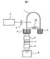
図1は末端検出を用いたキャピラリー電気泳動装置の基本構成を示す。レーザー2から射出された励起光は照射レンズ3でキャピラリー1に集光される。キャピラリー内で励起された蛍光は内部全反射により端面まで伝送される。端面から放射された蛍光は液槽4を介して集光レンズ6で平行光束にされ,フィルタ7で蛍光以外の光を遮断した後に,結像レンズ8でCCDカメラ9の光電面上に結像される。高圧電源26によって液槽4と液槽5の間に電圧が印加され,キャピラリー中を検体分子が電気泳動する。図2はキャピラリー断面の拡大図である。石英ガラス製のキャピラリーは,内径にDNA分離媒体が充填され,周囲にはポリマーがコーティングされている。本明細書では,図2に示したように,内径をD1,石英ガラスの外径をD2,コーティングを含めた最外径をD3で表す。
FIG. 1 shows a basic configuration of a capillary electrophoresis apparatus using end detection. The excitation light emitted from the
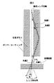
図3は蛍光を検出する側のキャピラリー端部の拡大図であり,末端検出における光線の伝播経路を示す。キャピラリー末端近傍ではキャピラリー中心軸と集光レンズ光軸は一致するので,以下では単に光軸と呼ぶ。レーザビームの照射点においては,光軸に対して同一の角度θで放射された2本の蛍光光線(光線1,光線2)を考える。図に示したように,末端検出では,蛍光は内径とガラス部の両方を伝播し,末端においてもこの両方から放射される。光線1は最終的に内径から放射される場合,光線2はガラス部から放射される場合に対応する。光線1及び光線2が,キャピラリー末端から放射され,液槽4底面を透過して空気中に出た時に光軸となす角度をそれぞれφ1,φ2とする。光線1及び2がガラス内に入ったときに光軸となす角は両方の光線について共通であるので,これをθgとする。内径内のDNA分離媒体の屈折率(≒1.4)<ガラスの屈折率(1.46)なので,光線はθ<θgとなるように屈折する。光線1のように,内径内に戻ってキャピラリー端面を出てゆく場合は,再度の屈折により,光線が光軸となす角はθに戻る。一方,光線2のようにガラス内に入ったまま端面から出てゆく場合には,屈折がほとんどおこらず,光線が光軸となす角はほとんどθgのままである。
FIG. 3 is an enlarged view of the end of the capillary on the fluorescence detection side, and shows the propagation path of the light beam in the end detection. In the vicinity of the end of the capillary, the capillary central axis and the optical axis of the condenser lens coincide with each other. At the irradiation point of the laser beam, consider two fluorescent rays (
この結果,最終的に空気中に出て行った状態においても,φ1<φ2となる。励起点では光軸に対して同一の角度θで放射された光線でも,内径から放射されれば集光レンズで集光され,ガラスから放射されると集光されない,ということがおこる。つまり,ガラス部から放射された光線に対する末端検出の効率は,内径から放射された光線に対するものに比べ低くなる。なお,内径から放射された光線に対する末端検出の集光効率は従来の直交検出の集光効率と実質的に同等である。以上の問題を定量的に議論するため,以下では図1の構成において,総量1の蛍光が励起点において等方的に放射され,端面から放射されて集光レンズ6で補足された蛍光はフィルタ7を100%透過し,CCDカメラ9の光電面上に倍率1でキャピラリー端面の蛍光像が結像されると仮定する。さらにCCD上では,端面像と同心の直径dの円形の領域で電荷をビニングする。このとき,CCDで検出される蛍光の量Sは以下の数1で表される。
As a result, φ1 <φ2 even in a state where it finally goes out into the air. At the excitation point, even if the light beam is emitted at the same angle θ with respect to the optical axis, it is collected by the condenser lens if it is emitted from the inner diameter, and is not collected if it is emitted from the glass. That is, the efficiency of end detection for light emitted from the glass portion is lower than that for light emitted from the inner diameter. In addition, the light collection efficiency of the end detection with respect to the light beam radiated from the inner diameter is substantially equal to the light collection efficiency of the conventional orthogonal detection. In order to discuss the above problem quantitatively, in the following, in the configuration of FIG. 1, a total amount of fluorescence is emitted isotropically at the excitation point and emitted from the end face and captured by the

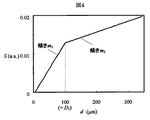
一般にNはdに対して単調に増加し,dが十分大きい時は直線的に増加する。図6は,図4と図5に基づいて求めた,S/Nとdの関係を示す。図6はD1=100の場合であるが,一般にS/Nはd=D1において最大となる。つまり末端検出においては,ビニング領域は内径とほぼ同程度にするのが良く,ビニング領域を広げて端面のガラス部分から放射された蛍光まで検出するとS/Nが下がってしまう。いいかえれば末端検出ではガラス部分から放射される蛍光は検出しても無駄であり,感度を高めるには内径から放射される蛍光の量を増やさなければならない。もし,ガラス外径を同一のまま,内径を小さくすると,蛍光のガラス部から放射される割合が増加し,内径から放射される割合が減少してしまう。これが内径を小さくしたとき,同時にガラス外径も小さくしなければならない理由である。 In general, N increases monotonously with respect to d, and increases linearly when d is sufficiently large. FIG. 6 shows the relationship between S / N and d obtained based on FIG. 4 and FIG. FIG. 6 shows the case where D 1 = 100, but generally the S / N is maximum at d = D 1 . That is, in the end detection, the binning region is preferably set to be approximately the same as the inner diameter, and if the binning region is expanded to detect the fluorescence emitted from the glass portion of the end surface, the S / N is lowered. In other words, in the end detection, the fluorescence emitted from the glass portion is useless even if it is detected, and the amount of fluorescence emitted from the inner diameter must be increased in order to increase the sensitivity. If the inner diameter of the glass is reduced while the outer diameter of the glass is the same, the ratio of the fluorescence emitted from the glass portion increases and the ratio of the emission from the inner diameter decreases. This is why when the inner diameter is reduced, the outer diameter of the glass must be reduced at the same time.
一方,すでに述べたように,末端検出の集光効率は,内径から放射される蛍光に対しては直交検出と同一である。従って,端面で内径から蛍光が放射される割合が100%である場合に,トータルでの集光効率が末端検出と直交検出で同一になる。現実にはガラス部を無くすことはできないので,ガラス部から放射される割合を0%とすることは不可能である。つまり,末端検出の集光効率は常に直交検出に若干劣っている。非特許文献1ではDNAシーケンシングが成功しているが,当業者としては、従来の直交検出方式のDNAシーケンサーのユーザーにとってはこれ以上の集光効率及び感度の低下は容認しがたいと考えるのが一般的である。そこで以下では,内径を80μm以下にし,なおかつ非特許文献1と同等以上の集光効率及び感度を維持する条件について詳細に検討する。
On the other hand, as already described, the light collection efficiency of end detection is the same as that of orthogonal detection for fluorescence emitted from the inner diameter. Therefore, when the ratio of the fluorescence emitted from the inner diameter at the end face is 100%, the total light collection efficiency is the same between the end detection and the orthogonal detection. In reality, since the glass part cannot be eliminated, it is impossible to reduce the rate of radiation from the glass part to 0%. In other words, the light collection efficiency of end detection is always slightly inferior to orthogonal detection. In
A.まず、第1の構成を以下に述べる。
上で述べたように,末端検出では内径から放射されて検出される蛍光のみが有効であり,この量が末端検出の集光効率を表す。この光量はビニング領域の直径d=D1としたときのSとして式(1)から求められ,
A. First, the first configuration will be described below.
As described above, in the end detection, only the fluorescence emitted and detected from the inner diameter is effective, and this amount represents the light collection efficiency of the end detection. This amount of light is obtained from equation (1) as S when the diameter of the binning area is d = D 1 ,
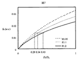
一方,F<1であるようなレンズは一般に収差が大きく,焦点距離及び作動距離が小さくて視野が狭いなどの短所が有る。非特許文献1ではF=0.95,焦点距離25mmのレンズを使用して,キャピラリー間クロストーク0.4%を実現しているが,医療応用などを考慮すると,DNAシーケンサーのクロストークはより低いことが望ましい。それには焦点距離が50mm以上の低収差のカメラレンズが望ましいが,このようなレンズは一般にF≧1であり,実用的にはF=1.1か1.2が限界である。図7が示すように,このようなレンズを用いる場合,非特許文献1(F=0.95,D1/D2=0.29)と同等以上のS0が得られる条件はD1/D2≧0.34となる。特に,工業的に製造しやすく低コストなF≧1.2のレンズを用いる場合には,D1/D2≧0.43が必要である。
On the other hand, lenses with F <1 generally have large aberrations and have disadvantages such as a small focal length and working distance and a narrow field of view. In
ここで、20μmより小さい内径は,つまり易い,レーザビームを照射しにくい,などの理由のため、内径は20μm以上にする必要がある。また、高電界を用いて分離能を高め、かつジュール熱の増加による電気泳動的分離能の低下を避けるために、内径を80μm以下とする。 Here, the inner diameter needs to be 20 μm or more because the inner diameter smaller than 20 μm is easy, that is, it is difficult to irradiate the laser beam. Further, in order to increase the resolution using a high electric field and avoid a decrease in electrophoretic resolution due to an increase in Joule heat, the inner diameter is set to 80 μm or less.
また,従来の直交検出では,集光レンズのFナンバーFを小さくすればするほど集光効率が向上する。しかしながら,末端検出では光軸となす角が,DNA分離媒体の屈折率npとキャピラリーコーティングの屈折率ncで決まるある値より大きい光線は全反射されず,伝送されない。その結果,Fをnpとncで決まるある値より小さくしても集光効率が上がらなくなる。集光効率はあがらなくても,Fが小さい明るいレンズほどコストは増大する。つまり,ある所定の値よりFを小さくすると全く無駄なコストが発生する。この無駄なコストを避ける条件は, In the conventional orthogonal detection, the light collection efficiency is improved as the F number F of the condenser lens is decreased. However, the optical axis and the angle formed by the end detection is greater light than a value determined by the refractive index n c of the refractive index n p and capillary coating of a DNA separation medium is not totally reflected, not transmitted. As a result, even if less than a certain value determined to F in n p and n c not rise collection efficiency. Even if the light condensing efficiency is not increased, the brighter lens having a smaller F increases the cost. That is, if F is made smaller than a certain predetermined value, a completely useless cost is generated. The condition to avoid this wasteful cost is
以上のように、本願第1の構成は、D1/D2≧0.34で20μm≦D1≦80μmとすることである。
As described above, the first configuration of the present application is such that D 1 / D 2 ≧ 0.34 and 20 μm ≦ D 1 ≦ 80 μm.
B.次に、第2の構成を述べる。
ビーム照射点での蛍光の放射量とCCDのノイズの影響を計算に入れ,最終的に非特許文献1と同等以上のS/Nが得られる条件を検討する。ビームが十分に絞られている場合,蛍光の発光量は内径に比例する。CCDのノイズは図5と同一とする。内径がそれぞれ50,75,100μmである場合のガラス外径とS/Nの関係を図8に示す。図8が示すように,非特許文献1の内径100μm,ガラス外径345μmの場合と同等のS/Nを得るには,内径50及び75μmの場合には,ガラス外径をそれぞれ128μm以下及び247μmとしなければならないことがわかる。図9は80μm以下の内径と,非特許文献1と同等以上のS/Nが維持できるガラス外径の上限値の関係を示す。内径が20μm以下の場合は,ガラス外径を内径より小さくしなければならないので,キャピラリーが存在し得ない。図9の曲線は20≦D1≦80の範囲で,
D2=−0.000328D1 3+0.0604D1 2+0.716D1―15
でほぼ完全に近似される。したがって,同等のS/Nを得つつ,良好な電気泳動性能を達成しうる条件は
20≦D1≦80かつ
D2≦−0.000328D1 3+0.0604D1 2+0.716D1―15
と表すことができる。
B. Next, a second configuration will be described.
The influence of the amount of fluorescent radiation at the beam irradiation point and the noise of the CCD is taken into account in the calculation, and the conditions under which an S / N equal to or higher than that of
D 2 = −0.000328D 1 3 + 0.0604D 1 2 + 0.716D 1 −15
Is approximated almost completely. Therefore, the conditions under which good electrophoretic performance can be achieved while obtaining the equivalent S / N are 20 ≦ D 1 ≦ 80 and D 2 ≦ −0.000328D 1 3 + 0.0604D 1 2 + 0.716D 1 −15
It can be expressed as.
末端検出の構成で,蛍光検出感度を維持しつつ内径を小さくすることができる。内径を小さくすることにより,高電界の使用が可能となり,分析が高速化されるとともに,分離能も向上する。 With the configuration of terminal detection, the inner diameter can be reduced while maintaining the fluorescence detection sensitivity. By reducing the inner diameter, it is possible to use a high electric field, speeding up the analysis and improving the resolution.
以下では本発明を実施するための最良の形態について具体的に記載する。 The best mode for carrying out the present invention will be specifically described below.
本発明の第一の実施例の基本構成は図1に示した通りである。ただし,キャピラリーの内径をD1[μm],ガラス外径をD2[μm]とするとき,
20≦D1≦80 (7)
かつ
D1/D2≧0.34 (8)
を満たすキャピラリーを用いる。また,キャピラリーのガラス表面は屈折率が1.4(分離媒体の屈折率)より小さいポリマーで少なくとも1部をコーティングされていなければならない。本実施例におけるコーティングの素材は屈折率nc=1.31の無色透明のテフロン(テフロンは登録商標)AF1600(デュポン)である。もちろん屈折率nc=1.29のテフロンAF2400(デュポン)でコーティングされたキャピラリーも好適に用いることができる。図10は本実施例で用いたキャピラリーの断面図と要求仕様を示す。コーティングの厚さは末端検出の性能に関係無いが,キャピラリーの機械的強度を保つために10μm以上が好ましく,15μm以上がより好ましい。本実施例ではD1=75,D2=220,D3=250であり,式(7)と(8)は満たされている。その結果,良好な電気泳動性能と集光効率を同時に得ることができる。また,コーティングの厚さを15μmとした結果十分な強度を得ることができた。D1とD2のペアーとしては式(7)と式(8)を満たす任意の組合せを用いることができ,例えば,(D1,D2)=(40,110),(50,130),(60,175)などを好適に用いることができる。
The basic configuration of the first embodiment of the present invention is as shown in FIG. However, when the inner diameter of the capillary is D 1 [μm] and the outer diameter of the glass is D 2 [μm],
20 ≦ D 1 ≦ 80 (7)
And
D 1 / D 2 ≧ 0.34 ( 8)
Use a capillary that fills. Also, the glass surface of the capillary must be coated at least partly with a polymer having a refractive index less than 1.4 (the refractive index of the separation medium). The coating material in this example is colorless and transparent Teflon (Teflon is a registered trademark) AF1600 (DuPont) having a refractive index n c = 1.31. Of course, a capillary coated with Teflon AF2400 (DuPont) having a refractive index n c = 1.29 can also be suitably used. FIG. 10 shows a cross-sectional view and required specifications of the capillary used in this example. The thickness of the coating is not related to the end detection performance, but is preferably 10 μm or more, more preferably 15 μm or more in order to maintain the mechanical strength of the capillary. In this embodiment, D 1 = 75, D 2 = 220, and D 3 = 250, and the expressions (7) and (8) are satisfied. As a result, good electrophoretic performance and light collection efficiency can be obtained at the same time. Further, as a result of setting the coating thickness to 15 μm, a sufficient strength could be obtained. As the pair of D 1 and D 2 , any combination satisfying the expressions (7) and (8) can be used. For example, (D 1 , D 2 ) = (40, 110), (50, 130) , (60, 175) and the like can be preferably used.
キャピラリーのコーティングを含めた外径は,375μmと150μmが規格化されて最も広く用いられている。非特許文献1においても外径375μmのキャピラリーが用いられている。一方,末端検出においてはコーティングの厚さは10μm以上なら任意であり,性能には関係が無い。例えばコーティング厚さを77.5μmとしてD1=75,D2=220,D3=375のキャピラリーを使用しても良い。このキャピラリーは最外径が非特許文献1と同一であるから,非特許文献1で用いられた電気泳動システムに,設計を変更すること無く,そのまま取り付けて使用することが可能である。しかも集光効率を維持したまま電気泳動性能が向上するという効果を得ることができる。
The outer diameter including the capillary coating is standardized to 375 μm and 150 μm and is most widely used.
本実施例ではDNA分離媒体の屈折率np=1.40,キャピラリーのコーティングの屈折率屈折率nc=1.31または1.29,集光カメラレンズのF=1.1としたので In this embodiment, the refractive index n p of the DNA separation medium is 1.40, the refractive index of the capillary coating is n c = 1.31 or 1.29, and F of the condenser camera lens is 1.1.
図11に本発明の第2の実施例の構成を示す。本実施例では、384本のキャピラリーを集積化し、キャピラリーアレイ101を形成している。また,各キャピラリーの全長は40cmである。各キャピラリー1−1〜1−384の、試料を導入する側を始端部102、電気泳動によって試料がキャピラリー内部を泳動し、溶出する側を終端部103と呼ぶ。各キャピラリー101の始端部102の端面より30cm(終端部103の端面より10cm)の位置をレーザ照射位置とし、その部分のキャピラリーのテフロンコーティングを除去してある。4個のガラス基板14−1〜14−4上のそれぞれに,96本のキャピラリー1−1〜1−96,1−93〜1−192, 1−193〜1−288及び1−289〜1−384のレーザ照射位置を並べ、4組のキャピラリー配列を形成する。各ガラス基板14−1〜14−4上では、各キャピラリー1−1〜1−384が互いにほぼ平行、かつガラス基板14−1〜14−4にほぼ平行に配列され、各レーザ照射位置が各キャピラリー1−1〜1−384とほぼ垂直で、かつ一直線上に配列されている。
FIG. 11 shows the configuration of the second embodiment of the present invention. In this embodiment, 384 capillaries are integrated to form a
アルゴンイオンレーザー光源2から発振したレーザ光(波長488nm、および515nm、出力100mW)は、ミラー10,ビームスプリッター12−1〜12−3およびミラー13によって4本に分割され、それぞれが照射レンズ3−1〜3−4(f=40mm)によってレーザ幅を絞られ、4組のキャピラリー配列を側面から照射する。各レーザビームは、ガラス基板14−1〜14−4に平行、かつ各キャピラリー1−1〜1−384に垂直になるように調節されてキャピラリー配列に照射される。電気泳動の分離能の低下を抑えるために、キャピラリー配列に照射されるレーザ幅は、キャピラリーの内径(50μm)程度かそれ以下にすることが望ましい。各キャピラリー1−1〜1−384の内部が分離媒体であるDNA分離媒体(Applied Biosytems社POP−7,屈折率1.4)で満たされている状態で上記のレーザ照射を行うと、特許文献1に記載されているように、レーザビームがキャピラリー配列中を伝搬するため、すべてのキャピラリーを同時に効率良く照射することができる。
The laser light (wavelengths 488 nm and 515 nm,
キャピラリーアレイ101の終端部103は、384本のキャピラリー1−1〜1−384が束ねられ、各キャピラリー1−1〜1−384の終端部103の端面は実質的に同一平面に並び、検出平面を形成する。検出平面上で各キャピラリー検出端面は96×4の格子状に配列(2次元的に配列)する。ここで、各キャピラリー1−1〜1−384の始端部102における位置とキャピラリー検出端面における位置を対応させておく。
The
キャピラリーアレイ101は、液槽4に接続されている。液槽4にはDNA分離媒体POP7が充填されており,液槽4からキャピラリーにPOP7が充填される。液槽4は、アクリル樹脂製であり、内部に流路が形成されている。この内部にDNA分離媒体が満たされている。チューブ19は、緩衝液(3700 buffer、Applied Biosystems社)の入った液槽21につながっている。本実施例ではDNA分離媒体として非架橋の粘性流体であるPOP7を用いたが,屈折率が同程度の架橋ゲルが充填されたキャピラリーも使用可能であることは云うまでも無い。
The
キャピラリー検出端面から出射された蛍光は、DNA分離媒体で満たされた流路、検出窓がはめ込まれた液槽4の底面を介し、液槽4下方向から、集光レンズ6(F=1.2、f=50)、フィルター7、プリズム28、結像レンズ8(F=1.2、f=50)、512×512画素の2次元CCDカメラ9で構成される検出部107によって検出される。
The fluorescence emitted from the capillary detection end face passes through the flow path filled with the DNA separation medium and the bottom surface of the
試料からの蛍光以外の、液槽4を構成する材料等から蛍光や散乱光を減らすため、検出窓の材料は無蛍光の石英ガラスとする。検出窓として、背蛍光や励起光を除外できる光学フィルターを使用しても良い。また、液槽4全体を無蛍光かつ透明な材料で作製し、液槽4と検出窓を一体化しても良い。本実施例では、検出平面から検出窓の外表面までの距離は20mmとし、集光レンズ6の焦点距離50mmより小とした。
In order to reduce fluorescence and scattered light from materials constituting the
キャピラリー始端部102を緩衝液に浸し、緩衝液槽21と液槽5との間に高圧電源506によって電圧を印加し、各キャピラリー1−1〜1−384に注入された試料を終端部103方向に電気泳動する。この際、キャピラリー1−1〜1−384内のDNA分離媒体が圧力差により移動しないように、緩衝液槽21に入った緩衝液と液槽5に入った緩衝液の液面の高低差がないようにした。
The capillary
各キャピラリー1−1〜1−384内を電気泳動する試料は、キャピラリー1−1〜1−384のレーザ照射位置においてレーザ照射される。レーザ照射により、試料に標識された蛍光体が励起され、その蛍光の一部はキャピラリー1−1〜1−384の内表面で全反射してキャピラリー1−1〜1−384内部を伝播し、各キャピラリー1−1〜1−384の検出端面より出射する。出射した蛍光は、液槽4の検出窓を介し、集光レンズ6により平行光束とされ、フィルター7により背蛍光および励起光が除外され、プリズム28によって波長分散され、結像レンズ8により2次元CCDカメラ9上に結像される。また、集光レンズ6の代わりに対物レンズを使用しても良い。集光レンズ6とキャピラリー検出端面の距離は50mmとした。各キャピラリー1−1〜1−384からの蛍光が波長分散された像は、2次元CCDカメラ9上の異なる位置に結像するようにする。これにより、各キャピラリー1−1〜1−384からの蛍光を独立かつ一括して検出できるようにする。また、この検出を連続的に繰り返すことにより、各キャピラリー1−1〜1−384からの蛍光の時間変化を計測する。得られた計測結果をコンピュータに記録し、解析することにより、複数種類の試料を分析できる。
A sample to be electrophoresed in each of the capillaries 1-1 to 1-384 is irradiated with a laser at a laser irradiation position of the capillaries 1-1 to 1-384. The fluorescent substance labeled on the sample is excited by the laser irradiation, and a part of the fluorescence is totally reflected on the inner surface of the capillary 1-1 to 1-384 and propagates inside the capillary 1-1 to 1-384. The light is emitted from the detection end faces of the capillaries 1-1 to 1-384. The emitted fluorescence is converted into a parallel light flux by the
蛍光検出時に外部からの迷光が検出部107に入ると、キャピラリー検出端面から出射した蛍光検出の感度の低下につながる。そこで、キャピラリー1−1〜1−384のレーザ照射位置から液槽4および検出部107の領域を外部から遮光することが望ましい。本実施例では、上記領域全体を暗箱で覆った。上記3つの領域に分けて暗箱で覆っても良い。また液槽4の材質を黒いアクリル樹脂にする、もしくは黒いプラスチックにし、外部からの迷光を遮断する方法でも良い。
When stray light from the outside enters the
図12にキャピラリー1−1〜1−384の断面と必要仕様を示す。本実施例で使用したキャピラリーに要求される仕様は第一の実施例におけるものとほぼ共通であるが,F=1.2のレンズを用いているので,
D1/D2≧0.43 (10)
を満たさなければならない。本実施例ではF=1.2であるが,F=1.4やF=1.8の場合も式(10)を当然満たさなければならない。本実施例ではD1=50,D2=100,D3=130として式(10)が満たされるようにした。D1とD2のペアーとしては式(6)と式(10)を満たす任意の組合せを用いることができ,例えば,(D1,D2)=(40,85),(60,130),(75,165)などを好適に用いることができる。
FIG. 12 shows a cross section and necessary specifications of the capillaries 1-1 to 1-384. The specifications required for the capillaries used in this example are almost the same as those in the first example, but because a lens with F = 1.2 is used,
D 1 / D 2 ≧ 0.43 ( 10)
Must be met. In this embodiment, F = 1.2, but naturally, the equation (10) must be satisfied even when F = 1.4 or F = 1.8. In this embodiment, D 1 = 50, D 2 = 100, and D 3 = 130, so that the formula (10) is satisfied. As the pair of D 1 and D 2 , any combination satisfying the expressions (6) and (10) can be used. For example, (D 1 , D 2 ) = (40, 85), (60, 130) , (75, 165) can be preferably used.
本実施例では,np=1.4,nc=1.31,F=1.2であるので式(6)が満たされており,第一の実施例同様無駄なレンズコストは発生していない。
本実施例では,内径を非特許文献1の半分とすることにより,3倍以上(320V/cm)の高電界を使用して安定なDNAシーケンシングができるようになった。本実施例では非特許文献1の4倍以上の384本のキャピラリーを集積化して,384試料の同時分析を可能とした。図13に,代表キャピラリー1−357で得られたシーケンシング波形を示す。試料は,ROXプライマーで標識された,M13mp18をテンプレートとする単色シーケンシング反応生成物である。529ベースまでの単一塩基分離が10分以内で達成された。つまり約500ベースを10分以内で解読できる。また,154ベースの平均泳動時間は6分であり,非特許文献1の6倍以上の高速分析が実現した。これらの性能は他の383本のキャピラリーでも同等であった。従ってトータルでは非特許文献1の25倍のスループットが,同等の集光効率を維持したまま実現された。
In this embodiment, since n p = 1.4, n c = 1.31, and F = 1.2, the expression (6) is satisfied, and a wasteful lens cost is generated as in the first embodiment. Not.
In this example, by making the inner diameter half that of
本実施例では、キャピラリーをビーム照射部及び検出部のいずれにおいても96本×4列で配置したが,別の配置,例えば128本×3列,192本×2列なども可能であり,ビーム照射部と検出部で別々の配置を取ることも可能である。例えば照射部で128本×3列,検出部で96×4列にすれば,レーザビームの照射効率が向上し,かつ,検出平面の幅はかわらないので,F1.2の明るい集光レンズを使うことが可能であり,一層高い感度を得ることができる。
本実施例では終端部103から液槽4を介して蛍光を検出したが,始端部102から液槽5を介して検出することも可能である。
In this embodiment, the capillaries are arranged in 96 × 4 rows in both the beam irradiation unit and the detection unit, but other arrangements, for example, 128 × 3 rows, 192 rows × 2 rows, etc. are possible. It is also possible to arrange the irradiation unit and the detection unit separately. For example, if the irradiation unit has 128 lines × 3 rows and the detection portion has 96 × 4 rows, the irradiation efficiency of the laser beam is improved and the width of the detection plane is not changed. It can be used, and higher sensitivity can be obtained.
In this embodiment, the fluorescence is detected from the
本実施例ではレーザビームをキャピラリーが配列する平面に平行に照射したが,図14に示したように,レーザのビームをシリンドリカルレンズ31で広げてキャピラリー1−1〜1−96に照射してもよい。この場合,照射部でキャピラリーが精密に配置される必要が無いので,キャピラリーアレイが安価に製造できるという効果がある。レーザビームをキャピラリーが配列する方向にスキャンすることによっても同様な効果を得られる。検出端でのキャピラリー配置を一列にするとプリズムのかわりに回折格子を用いることもできる。
In this embodiment, the laser beam is irradiated in parallel to the plane in which the capillaries are arranged. However, as shown in FIG. 14, the laser beam is spread by the
図15は本発明の第三の実施例におけるキャピラリーの断面図及び要求される仕様を示す。本実施例におけるキャピラリー電気泳動装置全体の構成は第一の実施例もしくは第二の実施例と同一である。キャピラリー内径内には屈折率約1.4のDNA分離媒体が充填される。本実施例ではキャピラリーの内径をD1[μm],ガラス外径をD2[μm]とするとき,
20≦D1≦80 (11)
かつ
FIG. 15 shows a cross-sectional view of the capillary and the required specifications in the third embodiment of the present invention. The configuration of the entire capillary electrophoresis apparatus in the present embodiment is the same as that in the first embodiment or the second embodiment. The inside diameter of the capillary is filled with a DNA separation medium having a refractive index of about 1.4. In this example, when the inner diameter of the capillary is D 1 [μm] and the outer diameter of the glass is D 2 [μm],
20 ≦ D 1 ≦ 80 (11)
And
本実施例では,np=1.4,nc=1.31であり,F≧1.2,つまり例えばF=1.4等であるので式(6)が満たされており,第一の実施例同様無駄なレンズコストは発生していない。 In this embodiment, n p = 1.4, n c = 1.31, and F ≧ 1.2, that is, for example, F = 1.4, so that equation (6) is satisfied, and the first As with the first embodiment, there is no wasteful lens cost.
本実施例では,キャピラリー電気泳動装置全体の構成は第一の実施例もしくは第二の実施例と同一であり,キャピラリー内径内には屈折率約1.4のDNA分離媒体が充填され,キャピラリーのガラス表面は屈折率が1.4より小さいポリマーでコーティングされている。電気泳動用のキャピラリーとしては,内径の呼び径75,50及び40μmのキャピラリーが規格化され,なおかつ電気泳動的に好ましいことから広く用いられている。キャピラリーの外径やコーティングが変化しても内径が同一ならば,ほぼ共通の電気泳動条件を適用できるという利点がある。そこで第四の実施例では,内径を75,50または40μmに固定して,式(8)を満たすキャピラリーを使用する。製造上,キャピラリーの内径は±3μm程度の誤差が避けられない。キャピラリーの内径を D1[μm],ガラス外径をD2[μm]とすると,呼び径75,50または40μmに対応するD1の範囲はそれぞれ75±3,50±3及び40±3である。これらの範囲のD1に対してD1/D2≧0.34を満たすD2の範囲はそれぞれ,D2≦229,D2≦156及びD2≦126である。従って本実施例におけるキャピラリーが満たすべき仕様は
(D1=75±3かつD2≦229)または
(D1=50±3かつD2≦156)または
(D1=40±3かつD2≦126)
となる。このようなキャピラリーを用いることにより,従来のCEシステムで最適化された電気泳動条件を容易に移植できるという固有の効果が得られる。
In this example, the entire configuration of the capillary electrophoresis apparatus is the same as that of the first example or the second example, and the inside diameter of the capillary is filled with a DNA separation medium having a refractive index of about 1.4. The glass surface is coated with a polymer having a refractive index of less than 1.4. As the capillaries for electrophoresis, capillaries having nominal inner diameters of 75, 50 and 40 μm are standardized and widely used because they are preferable for electrophoresis. If the inner diameter is the same even if the outer diameter or coating of the capillary changes, there is an advantage that almost common electrophoresis conditions can be applied. Therefore, in the fourth embodiment, a capillary satisfying the formula (8) is used with the inner diameter fixed at 75, 50, or 40 μm. In manufacturing, an error of about ± 3 μm is inevitable in the inner diameter of the capillary. If the inner diameter of the capillary is D 1 [μm] and the outer diameter of the glass is D 2 [μm], the range of D 1 corresponding to the nominal diameter of 75, 50, or 40 μm is 75 ± 3, 50 ± 3, and 40 ± 3, respectively. is there. Each range of D 2 is satisfying D 1 / D 2 ≧ 0.34 with respect to D 1 of the these ranges, a D 2 ≦ 229, D 2 ≦ 156 and D 2 ≦ 126. Therefore, the specifications to be satisfied by the capillary in this embodiment are (D 1 = 75 ± 3 and D 2 ≦ 229) or (D 1 = 50 ± 3 and D 2 ≦ 156) or (D 1 = 40 ± 3 and D 2 ≦ 126)
It becomes. By using such a capillary, it is possible to obtain an inherent effect that the electrophoresis conditions optimized by the conventional CE system can be easily transplanted.
本実施例では,np=1.4,nc=1.31であり,F≧1.2,つまり例えばF=1.4等であるので式(6)が満たされており,第一の実施例同様無駄なレンズコストは発生していない。 In this embodiment, n p = 1.4, n c = 1.31, and F ≧ 1.2, that is, for example, F = 1.4, so that equation (6) is satisfied, and the first As with the first embodiment, there is no wasteful lens cost.
本発明は超高スループットのDNAシーケンサーに利用できる。 The present invention can be used for an ultra-high throughput DNA sequencer.
1,1−1〜1−384:キャピラリー,2:レーザ,3,3−1〜3−4:照射レンズ,4:液槽,5:液槽,6:集光レンズ,7:フィルタ,8:結像レンズ,9:CCDカメラ,10,12−1〜12−3:ビームスプリッター,11, 13:ミラー,14−1〜14−4:ガラス基板,15:シリンジ,19:チューブ,20:バルブ,21:液槽,26:高圧電源,28:プリズム,31:シリンドリカルレンズ。 1, 1-1 to 1-384: capillary, 2: laser, 3, 3-1 to 3-4: irradiation lens, 4: liquid tank, 5: liquid tank, 6: condenser lens, 7: filter, 8 : Imaging lens, 9: CCD camera, 10, 12-1 to 12-3: Beam splitter, 11, 13: Mirror, 14-1 to 14-4: Glass substrate, 15: Syringe, 19: Tube, 20: Valve: 21: Liquid tank, 26: High-voltage power supply, 28: Prism, 31: Cylindrical lens.
Claims (16)
前記キャピラリーの一方の端部側に設けられた液槽と、
前記液槽を介して、前記試料の成分から発する蛍光を検出する検出器とを有し、
前記キャピラリーの内径をD1[μm],ガラス外径をD2[μm]とするとき,
20≦D1≦80 かつ D1/D2≧0.34
であることを特徴とするキャピラリー電気泳動装置。 A cylindrical glass capillary in which a sample is separated by electrophoresis in a separation medium packed inside;
A liquid tank provided on one end side of the capillary;
A detector for detecting fluorescence emitted from the components of the sample via the liquid tank;
When the inner diameter of the capillary is D 1 [μm] and the outer diameter of the glass is D 2 [μm],
20 ≦ D1 ≦ 80 and D 1 / D 2 ≧ 0.34
A capillary electrophoresis apparatus characterized by
前記レンズのFナンバーが1.0以上であることを特徴とする請求項1記載のキャピラ
リー電気泳動装置。 Between the liquid tank and the detector, a lens for collecting the fluorescence is provided,
2. The capillary electrophoresis apparatus according to claim 1, wherein the F number of the lens is 1.0 or more.
前記レンズのFナンバーが1.2以上であって,D1/D2≧0.43であることを特
徴とする請求項1記載のキャピラリー電気泳動装置。 Between the liquid tank and the detector, a lens for collecting the fluorescence is provided,
2. The capillary electrophoresis apparatus according to claim 1, wherein an F number of the lens is 1.2 or more and D 1 / D 2 ≧ 0.43.
に記載のキャピラリー電気泳動装置。 2. The refractive index of the separation medium is 1.36 or more and 1.42 or less.
Capillary electrophoresis apparatus according to claim 1.
前記ガラス製キャピラリーの外表面の少なくとも一部は、ポリマーでコーティングされ
,前記ポリマーの屈折率をnc,前記分離媒体の屈折率をnp,前記レンズのFナンバー
をFとするとき,
0.5/(np 2−nc 2)0.5≦F
であることを特徴とする請求項1記載のキャピラリー電気泳動装置。 Between the liquid tank and the detector, a lens for collecting the fluorescence is provided,
When at least a part of the outer surface of the glass capillary is coated with a polymer, the refractive index of the polymer is n c , the refractive index of the separation medium is n p , and the F number of the lens is F,
0.5 / (n p 2 -n c 2) 0.5 ≦ F
The capillary electrophoresis apparatus according to claim 1, wherein:
ー電気泳動装置。 6. The capillary electrophoresis apparatus according to claim 5, wherein np is 1.36 or more and 1.42 or less.
ラリー電気泳動装置。 The capillary electrophoresis apparatus according to claim 5, wherein the coating has a thickness of 10 μm or more.
5記載のキャピラリー電気泳動装置。 6. The capillary electrophoresis apparatus according to claim 5, wherein the refractive index of the polymer is smaller than the refractive index of the separation medium.
特徴とする請求項1記載のキャピラリー電気泳動装置。 2. The capillary electrophoresis apparatus according to claim 1, wherein a plurality of capillaries are provided, and the one end is two-dimensionally arranged.
前記キャピラリー配列毎に、前記キャピラリーの側面から光を照射する光源とを有する
ことを特徴とする請求項1記載のキャピラリー電気泳動装置。 The capillaries are provided so that a plurality of sets of capillary arrays are formed,
The capillary electrophoresis apparatus according to claim 1, further comprising a light source that emits light from a side surface of the capillary for each capillary array.
と、前記光源と前記キャピラリーとの間に、前記光ビームを前記キャピラリーが並ぶ方向
に広げるレンズとを有することを特徴とする請求項1記載のキャピラリー電気泳動装置。 A plurality of the capillaries are provided, the light source irradiating the plurality of capillaries with a light beam, and a lens that spreads the light beam in the direction in which the capillaries are arranged between the light source and the capillaries. The capillary electrophoresis apparatus according to claim 1.
と、
前記キャピラリーを延長した方向から、前記試料の成分から発する蛍光を検出する検出
器とを有し、
前記キャピラリーの内径をD1[μm],ガラス外径をD2[μm]とするとき,
20≦D1≦80 かつ
D2≦−0.000328D1 3+0.0604D1 2+0.716D1―15
であることを特徴とするキャピラリー電気泳動装置。 A cylindrical glass capillary in which a sample is separated by electrophoresis in a separation medium packed inside;
A detector that detects fluorescence emitted from components of the sample from the direction in which the capillary is extended;
When the inner diameter of the capillary is D 1 [μm] and the outer diameter of the glass is D 2 [μm],
20 ≦ D1 ≦ 80 and D2 ≦ −0.000328D 1 3 + 0.0604D 1 2 + 0.716D 1 −15
A capillary electrophoresis apparatus characterized by
2に記載のキャピラリー電気泳動装置。 2. The refractive index of the separation medium is 1.36 or more and 1.42 or less.
2. A capillary electrophoresis apparatus according to 2.
前記キャピラリー配列毎に、前記キャピラリーの側面から光を照射する光源とを有する
ことを特徴とする請求項12記載のキャピラリー電気泳動装置。 The capillaries are provided so that a plurality of sets of capillary arrays are formed,
The capillary electrophoresis apparatus according to claim 12, further comprising a light source that emits light from a side surface of the capillary for each capillary array.
前記キャピラリーの一方の端部側に設けられた液槽と、
前記液槽を介して、前記試料の成分から発する蛍光を検出する検出器とを有し、
前記キャピラリーの内径をD1[μm],ガラス外径をD2[μm]とするとき,
(D1=75±3かつD2≦229)または
(D1=50±3かつD2≦156)または
(D1=40±3かつD2≦126)
であることを特徴とするキャピラリー電気泳動装置。 A cylindrical glass capillary in which a sample is separated by electrophoresis in a separation medium packed inside;
A liquid tank provided on one end side of the capillary;
A detector for detecting fluorescence emitted from the components of the sample via the liquid tank;
When the inner diameter of the capillary is D 1 [μm] and the outer diameter of the glass is D 2 [μm],
(D 1 = 75 ± 3 and D2 ≦ 229) or (D 1 = 50 ± 3 and D2 ≦ 156) or (D 1 = 40 ± 3 and D2 ≦ 126)
A capillary electrophoresis apparatus characterized by
前記レンズのFナンバーが1.0以上であることを特徴とする請求項15記載のキャピ
ラリー電気泳動装置。 Between the liquid tank and the detector, a lens for collecting the fluorescence is provided,
16. The capillary electrophoresis apparatus according to claim 15, wherein the F number of the lens is 1.0 or more.
Priority Applications (2)
| Application Number | Priority Date | Filing Date | Title |
|---|---|---|---|
| JP2004088305A JP4045253B2 (en) | 2004-03-25 | 2004-03-25 | Capillary and electrophoresis device |
| US11/006,535 US20050211558A1 (en) | 2004-03-25 | 2004-12-08 | Capillary and electrophoresis apparatus |
Applications Claiming Priority (1)
| Application Number | Priority Date | Filing Date | Title |
|---|---|---|---|
| JP2004088305A JP4045253B2 (en) | 2004-03-25 | 2004-03-25 | Capillary and electrophoresis device |
Publications (2)
| Publication Number | Publication Date |
|---|---|
| JP2005274365A JP2005274365A (en) | 2005-10-06 |
| JP4045253B2 true JP4045253B2 (en) | 2008-02-13 |
Family
ID=34988472
Family Applications (1)
| Application Number | Title | Priority Date | Filing Date |
|---|---|---|---|
| JP2004088305A Expired - Lifetime JP4045253B2 (en) | 2004-03-25 | 2004-03-25 | Capillary and electrophoresis device |
Country Status (2)
| Country | Link |
|---|---|
| US (1) | US20050211558A1 (en) |
| JP (1) | JP4045253B2 (en) |
Cited By (1)
| Publication number | Priority date | Publication date | Assignee | Title |
|---|---|---|---|---|
| US9753274B2 (en) | 2014-07-31 | 2017-09-05 | Jsr Corporation | Display element, photosensitive composition and electrowetting display |
Families Citing this family (4)
| Publication number | Priority date | Publication date | Assignee | Title |
|---|---|---|---|---|
| JP4408906B2 (en) * | 2007-03-05 | 2010-02-03 | 株式会社日立ハイテクノロジーズ | Capillary electrophoresis device |
| ES2848532T3 (en) * | 2007-03-26 | 2021-08-10 | Qiagen Sciences Llc | Capillary electrophoresis using transparent coated capillary tubes |
| EP2433120A1 (en) * | 2009-05-20 | 2012-03-28 | Agilent Technologies, Inc. | Flow cell exploiting radiation within cell wall |
| CN113203757B (en) * | 2021-05-07 | 2024-03-22 | 北京市辐射中心 | All-optical X-ray microscopic imaging system |
Family Cites Families (6)
| Publication number | Priority date | Publication date | Assignee | Title |
|---|---|---|---|---|
| US5798032A (en) * | 1994-06-02 | 1998-08-25 | The Perkin-Elmer Corporation | Method and apparatus for automated carbohydrate mapping and sequencing |
| US5582705A (en) * | 1995-05-19 | 1996-12-10 | Iowa State University Research Foundation, Inc. | Multiplexed capillary electrophoresis system |
| FR2774472B1 (en) * | 1998-01-30 | 2000-04-21 | Centre Nat Rech Scient | IMPROVEMENTS IN MULTI-CAPILLARY ELECTROPHORESIS SYSTEMS |
| US6596140B2 (en) * | 2001-05-01 | 2003-07-22 | Applera Corporation | Multi-channel capillary electrophoresis device and method |
| US7250098B2 (en) * | 2001-09-28 | 2007-07-31 | Applera Corporation | Multi-capillary array electrophoresis device |
| JP4152126B2 (en) * | 2002-05-31 | 2008-09-17 | 株式会社日立ハイテクノロジーズ | Electrophoresis device |
-
2004
- 2004-03-25 JP JP2004088305A patent/JP4045253B2/en not_active Expired - Lifetime
- 2004-12-08 US US11/006,535 patent/US20050211558A1/en not_active Abandoned
Cited By (1)
| Publication number | Priority date | Publication date | Assignee | Title |
|---|---|---|---|---|
| US9753274B2 (en) | 2014-07-31 | 2017-09-05 | Jsr Corporation | Display element, photosensitive composition and electrowetting display |
Also Published As
| Publication number | Publication date |
|---|---|
| JP2005274365A (en) | 2005-10-06 |
| US20050211558A1 (en) | 2005-09-29 |
Similar Documents
| Publication | Publication Date | Title |
|---|---|---|
| US6224733B1 (en) | DNA detector and DNA detection method | |
| US5439578A (en) | Multiple capillary biochemical analyzer | |
| EP1835281B1 (en) | Multiplexed capillary electrophoresis system | |
| JPH09288088A (en) | Capillary array electrophoretic apparatus | |
| JP2007163488A (en) | Multicapillary electrophoretic fluorescence system | |
| US7419578B2 (en) | Capillary electrophoresis apparatus | |
| JP2000131282A (en) | Capillary array electrophoretic device | |
| JP2776208B2 (en) | Electrophoresis device | |
| JPH0663964B2 (en) | Micro flow cell | |
| JP4045253B2 (en) | Capillary and electrophoresis device | |
| JPH04223261A (en) | Reading device of fluorescent pattern | |
| JP4491325B2 (en) | Capillary electrophoresis device | |
| JP2005070031A (en) | Component analyzer using microchip | |
| US20100163715A1 (en) | Light Focusing in Linear Channel Arrays | |
| JP3839412B2 (en) | Fluorescence detection type capillary array electrophoresis apparatus | |
| JP4431421B2 (en) | Capillary electrophoresis device | |
| JP2000097908A (en) | Electrophoresis apparatus | |
| JP3042487B2 (en) | Electrophoresis device | |
| JP3296351B2 (en) | Electrophoresis device | |
| JP4078324B2 (en) | Electrophoresis apparatus and capillary array | |
| JP3042370B2 (en) | Electrophoresis device | |
| JP3562514B2 (en) | Capillary array | |
| JP3599060B2 (en) | Electrophoresis device | |
| JP2005010180A (en) | Electrophoresis apparatus | |
| JP2006105871A (en) | Electrophoretic system |
Legal Events
| Date | Code | Title | Description |
|---|---|---|---|
| A977 | Report on retrieval |
Free format text: JAPANESE INTERMEDIATE CODE: A971007 Effective date: 20060320 |
|
| RD04 | Notification of resignation of power of attorney |
Free format text: JAPANESE INTERMEDIATE CODE: A7424 Effective date: 20060509 |
|
| A131 | Notification of reasons for refusal |
Free format text: JAPANESE INTERMEDIATE CODE: A131 Effective date: 20060919 |
|
| A521 | Written amendment |
Free format text: JAPANESE INTERMEDIATE CODE: A523 Effective date: 20061109 |
|
| TRDD | Decision of grant or rejection written | ||
| A01 | Written decision to grant a patent or to grant a registration (utility model) |
Free format text: JAPANESE INTERMEDIATE CODE: A01 Effective date: 20071106 |
|
| A61 | First payment of annual fees (during grant procedure) |
Free format text: JAPANESE INTERMEDIATE CODE: A61 Effective date: 20071119 |
|
| R150 | Certificate of patent or registration of utility model |
Ref document number: 4045253 Country of ref document: JP Free format text: JAPANESE INTERMEDIATE CODE: R150 Free format text: JAPANESE INTERMEDIATE CODE: R150 |
|
| FPAY | Renewal fee payment (event date is renewal date of database) |
Free format text: PAYMENT UNTIL: 20101122 Year of fee payment: 3 |
|
| FPAY | Renewal fee payment (event date is renewal date of database) |
Free format text: PAYMENT UNTIL: 20101122 Year of fee payment: 3 |
|
| FPAY | Renewal fee payment (event date is renewal date of database) |
Free format text: PAYMENT UNTIL: 20111122 Year of fee payment: 4 |
|
| FPAY | Renewal fee payment (event date is renewal date of database) |
Free format text: PAYMENT UNTIL: 20111122 Year of fee payment: 4 |
|
| FPAY | Renewal fee payment (event date is renewal date of database) |
Free format text: PAYMENT UNTIL: 20121122 Year of fee payment: 5 |
|
| FPAY | Renewal fee payment (event date is renewal date of database) |
Free format text: PAYMENT UNTIL: 20121122 Year of fee payment: 5 |
|
| FPAY | Renewal fee payment (event date is renewal date of database) |
Free format text: PAYMENT UNTIL: 20131122 Year of fee payment: 6 |
|
| S531 | Written request for registration of change of domicile |
Free format text: JAPANESE INTERMEDIATE CODE: R313531 |
|
| S533 | Written request for registration of change of name |
Free format text: JAPANESE INTERMEDIATE CODE: R313533 |
|
| R350 | Written notification of registration of transfer |
Free format text: JAPANESE INTERMEDIATE CODE: R350 |