JP4041588B2 - Filtration device - Google Patents
Filtration device Download PDFInfo
- Publication number
- JP4041588B2 JP4041588B2 JP21222798A JP21222798A JP4041588B2 JP 4041588 B2 JP4041588 B2 JP 4041588B2 JP 21222798 A JP21222798 A JP 21222798A JP 21222798 A JP21222798 A JP 21222798A JP 4041588 B2 JP4041588 B2 JP 4041588B2
- Authority
- JP
- Japan
- Prior art keywords
- raw water
- casing
- filtration
- water
- chamber
- Prior art date
- Legal status (The legal status is an assumption and is not a legal conclusion. Google has not performed a legal analysis and makes no representation as to the accuracy of the status listed.)
- Expired - Lifetime
Links
Images


Description
【0001】
【技術分野】
本願発明は、異物を含有する各種の水(原水)の濾過処理を効率良く行うための濾過装置に関する。
【0002】
【従来の技術】
従来、濾過装置の具体例としては、特公平2−18890号公報に記載の濾過装置がある。この従来の濾過装置は、本願の図4に示すように、原水流入管90やドレン管91を有するケーシング92内に、略円筒状の濾過エレメント93を設けたものであり、この濾過エレメント93の底部には処理水排出管94が接続されている。上記原水流入管90は、原水を上記ケーシング92の上部からその内部へ上記ケーシング92の接線方向に流入させるように設けられている。
【0003】
このような構成の濾過装置によれば、原水流入管90からケーシング92内に流入した原水が濾過エレメント93を中心として旋回する渦巻流となり、この原水が濾過エレメント93の外周面に接触しつつ、この濾過エレメント93の多数の透孔93aを透過して原水の濾過処理がなされる。そして、この濾過された処理水は、処理水排出管94を介して外部に排出される。したがって、原水の濾過処理を連続して行うことができる。
【0004】
【発明が解決しようとする課題】
しかしながら、上記従来の濾過装置では、次のような不具合を生じていた。
【0005】
すなわち、従来では、濾過エレメント93の上部から下部に進行する原水の渦巻流を生じさせて、この渦巻流を濾過エレメント93の外周面に接触させているために、この原水の渦巻流に含まれている種々の異物は、そのサイズや比重の大小を問うことなく濾過エレメント93の外周面に無差別に接触する。このため、濾過エレメント93に対する異物の接触度合いが多くなる。とくに、従来では、濾過エレメント93の外周囲において原水の渦巻流を発生させているが、このような原水の渦巻流を発生させると、その渦巻流の中心部に異物が集まり易くなるという特有の現象がみられるために、濾過エレメント93の外周面への異物の接触度合いは一層多くなる。したがって、従来では、濾過エレメント93の透孔93aに原水中の異物が詰まり易くなっており、濾過装置の濾過処理能率が短時間で低下するという不具合が生じていた。また、目詰まりした濾過エレメント93の洗浄作業を頻繁に行う必要も生じ、その作業も煩わしいものとなっていた。
【0006】
本願発明は、このような事情のもとで考え出されたものであって、濾過エレメントに目詰まりを容易に生じさせないようにして原水の濾過処理を連続して効率良く行うことができるようにすることをその課題としている。
【0007】
【発明の開示】
上記の課題を解決するため、本願発明では、次の技術的手段を講じている。
【0012】
本願発明によって提供される濾過装置は、周面部に多数の透孔を有する筒状の濾過エレメントと、この濾過エレメントを略鉛直状に起立させた姿勢で内部に設けているとともに、上記濾過エレメントの下方に原水流入室を形成しているケーシングと、上記ケーシングの外部から上記原水流入室内にこの原水流入室の周壁部の接線方向に原水を流入させるための原水流入口と、上記原水流入室から上記濾過エレメントの内側に進行した原水が上記複数の透孔を通過して得られた処理水を上記ケーシングの外部へ排出させるための処理水排出口と、を具備しており、上記ケーシング内の上記原水流入室の下方には、この原水流入室内に流入した原水を一部流入させて貯留可能な底部貯水室が設けられているとともに、この底部貯水室には、開閉バルブを備えたドレン抜きパイプが設けられており、かつ、上記原水流入室と上記底部貯水室とは、略中央部に開口孔を有する区画板を介して区画されていることに特徴づけられる。
【0013】
本願発明の濾過装置では、原水流入口からケーシング内の原水流入室内に原水を流入させて、ケーシング内の各部に適当量の原水を満たすと、この原水は上記原水流入室の周壁部の接線方向に流入することによって渦巻流にできるとともに、この原水流入室内に発生させた原水の渦巻流を上記濾過エレメントの下方から上記濾過エレメントの内側に向けて進行させることができる。そして、上記濾過エレメントの内側に向けて進行した原水が上記濾過エレメントの周面部の透孔を通過して濾過されると、その処理水は処理水排出口を介してケーシングの外部に排出されることとなる。そうして、上記濾過装置を用いれば、原水に含まれている比重の大きな異物については、原水流入室から濾過エレメントの内側へ向けて上昇しないようにできるとともに、それ以外の異物については、濾過エレメントの内側を進行する原水の渦巻流の中央部に集めるようにして、濾過エレメントの周面部に対する異物の接触度合いを少なくすることができる。さらには、濾過エレメントに目詰まりが生じることを原水の渦巻流によって防止することも可能となり、濾過エレメントに目詰まりを極力生じさせないようにして、原水の連続した濾過処理を効率良く行うことができる。
【0015】
また、原水流入室に流入した原水に含まれている比重の大きな異物を原水流入室からその下方の底部貯水室に流れ込ませておくことにより、比重の大きな異物が原水の渦巻流に紛れ込んで濾過エレメントの内側へ不用意に流れ込んでしまうことを抑制することが可能となる。また、上記底部貯水室内に流れ込んだ異物の量が多くなった場合には、開閉バルブを開くことによって上記異物をドレン抜きパイプからケーシングの外部へ簡単に排出させることができ、異物の排出処理も容易に行える。
【0017】
さらに、原水流入室と底部貯水室とを区画板を介して区画しておくことができるために、底部貯水室内に流れ込んでいる異物が原水流入室を通過して濾過エレメントの内側に到達することをより適切に抑制することが可能となる。一方、上記区画板の略中央部には開口孔が設けられているために、比重の大きな異物については、この開口孔を介して原水流入室から底部貯水室内に適切に流れ込ませることができる。
【0018】
本願発明の他の好ましい実施の形態では、上記ケーシング内の上記濾過エレメントの上方には、上記濾過エレメントの内側を通過してきた原水を一部流入させて貯留可能な上部貯水室が設けられているとともに、この上部貯水室には、開閉バルブを備えた排水用パイプが設けられている。
【0019】
このような構成によれば、濾過エレメントの内側を通過した原水をこの濾過エレメントよりも上方に設けられている上部貯水室で貯留させることができるが、この上部貯水室には、原水の渦巻流の中央部に集められた異物のうち比重が比較的小さい異物を浮遊させることができる。このように上部貯水室内に異物を浮遊させておけば、この異物が濾過エレメントの周面部に接触しないようにすることができ、濾過エレメントに目詰まりをより生じ難くすることができる。また、上記上部貯水室内に浮遊する異物の量が多くなった場合には、開閉バルブを開けることにより、上記異物を上部貯水室内の原水とともに排水用パイプを介して外部に適切に取り出すことができる。
【0020】
本願発明の他の好ましい実施の形態では、上記ケーシングの周壁部には、上記濾過エレメントの周面部に洗浄水を噴射する1または複数の洗浄水噴射ノズルが設けられているとともに、上記ケーシングの上部には、上記濾過エレメントをその軸心周りに回転させる駆動手段が設けられている。
【0021】
このような構成によれば、濾過エレメントに仮に目詰まりが生じた場合であっても、駆動手段によって濾過エレメントをその軸心周りに回転させながらその周面部に対して洗浄水噴射ノズルから洗浄水を噴射させることによって、濾過エレメントの周面部を洗浄し、その目詰まり状態を適切に解消することができる。したがって、原水の濾過処理効率を高める上で、一層好ましいものとなる。また、このような濾過エレメントの洗浄処理は、原水の濾過処理を行っている最中に行うことが可能であり、濾過エレメントの洗浄処理のために原水の濾過処理を中断するような必要もない。さらに、上記濾過エレメントを回転させるための駆動手段は、ケーシングの上部に設けられているために、装置全体の幅方向のサイズが嵩張らないようにできる。また、濾過エレメントを回転させるための具体的な機構としては、ケーシングの上部に設けられた駆動手段と濾過エレメントとを適当な連結部材を介して直結した構造とすればよいから、その構造も非常に簡素なものにできる。
【0022】
本願発明のその他の特徴および利点は、以下に行う発明の実施の形態の説明から、より明らかになるであろう。
【0023】
【発明の実施の形態】
以下、本願発明の好ましい実施の形態について、図面を参照しつつ具体的に説明する。
【0024】
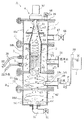
図1は、本願発明に係る濾過装置の一例を示す断面図である。図2は、図1のII−II断面図である。図3は、図1のIII −III 断面図である。
【0025】
図1において、この濾過装置Aは、ケーシング1、濾過エレメント2、この濾過エレメント2を回転させるための駆動機構4、複数の洗浄水噴射ノズル3、およびその他後述する各部を具備して構成されている。
【0026】
上記ケーシング1は、その全体の材質がたとえば防錆性に優れたステンレス製とされており、複数のケーシング本体10a〜10dを上下方向(鉛直方向)に一連に連結して構成されている。これら複数のケーシング本体10a〜10dは、複数本のボルト11を介して互いに連結が可能なフランジ部を有する複数の略円筒状または有底の略円筒状である。上記ケーシング1の内部には、上部貯水室12、処理水排出室13、原水流入室14、および底部貯水室15が形成されている。
【0027】
上記原水流入室14は、ケーシング本体10cの内部に形成されており、濾過エレメント2よりも下方に位置している。この原水流入室14の略円筒状の周壁部14aには原水流入口5Aが設けられている。この原水流入口5Aは、上記ケーシング本体10cに取付けられた管体50の先端開口部に相当しており、この管体50には貯留タンク7に一端が繋がった原水供給用配管70の他端が接続されている。この原水供給用配管70にはポンプPが設けられており、このポンプPの吐出圧によって上記貯留タンク7内の原水が上記原水流入口5Aに供給されるように構成されている。図2によく表れているように、上記管体50は、その軸長方向が上記周壁部14aの接線方向に延びるように設けられており、原水流入口5Aは上記原水流入室14の中央部には対向しないように上記周壁部14aの偏った位置に設けられている。このため、上記原水流入口5Aから原水流入室14内に流入した原水Wは、上記原水流入室14の周壁部14aの内面に沿って旋回する渦巻流となる。
【0028】
図1において、上記底部貯水室15は、有底状のケーシング本体10dの内部に形成されており、上記原水流入室14の下方に位置している。この底部貯水室15の底部には、開閉バルブ60を備えたドレン抜きパイプ61が連結されている。上記開閉バルブ60は、遠隔操作によってその開閉動作が可能な開閉バルブとされている。ただし、手動操作式のバルブとされていてもかまわない。これは、後述する他の開閉バルブ66やエア抜き用バルブ68についても同様である。上記底部貯水室15は、ケーシング1に固定して取付けられた区画板62を介して上記原水流入室14と区画されている。ただし、上記区画板62は、その略中央部に貫通孔としての開口孔63を形成した中空円板状であり、上記底部貯水室15と原水流入室14とは上記開口孔63を介して互いに連通している。
【0029】
上記処理水排出室13は、ケーシング本体10bの内部のうち、上記濾過エレメント2の外周囲に形成されている。この処理水排出室13は、濾過エレメント2によって濾過された水(処理水)を一時的に収容させておくための室であり、2つの仕切板64,65を介して上部貯水室12や原水流入室14とは仕切られている。この処理水排出室13の周壁部には、処理水排出口5Bが設けられている。この処理水排出口5Bは、上記ケーシング本体10bに取付けられた管体51の先端開口部に相当している。
【0030】
上記上部貯水室12は、上記ケーシング本体10aの内部に形成されており、上記濾過エレメント2よりも上方に位置している。この上部貯水室12の周壁部の底部近傍には、開閉バルブ66を有する排水用パイプ67が連結されている。この上部貯水室12の上部は蓋体16により密閉されている。ただし、この蓋体16にはエア抜き用バルブ68が設けられており、このエア抜き用バルブ68を閉状態としたときには、上記ケーシング1の内部を密閉または略密閉状態に設定できるように構成されている。上記エア抜き用バルブ68を開状態としたときには、上記ケーシング1内の密閉または略密閉状態が解除されるが、これはケーシング1内の原水Wを外部に排出させる場合にこれを短時間で迅速に行わせるのに好適となる。
【0031】
上記濾過エレメント2は、好ましくはステンレスなどの防錆性に優れた材質からなり、ケーシング1よりも小径の略円筒状に形成されている。この濾過エレメント2の周面部の全体または一部の領域には、多数の透孔20が形成されている。これら多数の透孔20は、ケーシング1の周面部の厚み方向に貫通した孔であり、その直径はたとえば十分の数ミリ程度である。この濾過エレメント2は、上記ケーシング本体10bの内側に略鉛直状に起立した姿勢に設けられており、この濾過エレメント2の内側領域21は原水流入室14と上部貯水室12とのそれぞれに連通している。また、この濾過エレメント2は、その軸心周りに回転できるように仕切板64,65に対して摺動可能である。
【0032】
上記駆動機構4は、上記ケーシング1の上部、より厳密には上記蓋体16の上面部に取付けられたモータMと、このモータMの駆動軸と上記濾過エレメント2の上部とを連結する複数の連結部材40,41とを具備して構成されている。連結部材40は、上記濾過エレメント2の上部に嵌合して連結された筒状の部材である。これに対して、連結部材41は、上記連結部材40よりも上方に進んだ原水を上部貯水室12内の各部に流れ込ませることが可能なアーム状の部材である。上記駆動機構4は、上記モータMを駆動させることによって上記濾過エレメント2をその軸心周りに回転させるように動作するものである。ただし、好ましくは、図3に示すように、上記濾過エレメント2の回転方向N1は、原水Wの渦巻方向N2とは逆方向となるように設定されている。さらに好ましくは、上記モータMは、図示しないタイマ設定装置によって予め設定された一定時間ごとに所定時間だけ駆動させることができるように構成されている。
【0033】
図1において、上記複数の洗浄水噴射ノズル3は、配管30を介して一定の水圧で供給されてくる洗浄水を噴射するものであり、濾過エレメント2の周面部の外周面に向けて洗浄水を噴射できるようにケーシング1の周壁部に取付けられている。好ましくは、これら複数の洗浄水噴射ノズル3は、上記モータMが駆動して濾過エレメント2が回転しているときにのみこれに連動して洗浄水を濾過エレメント2に向けて噴射できるように構成されている。上記洗浄水としては、水道水、あるいはこの濾過装置Aによって得られた処理水などを用いることが可能である。
【0034】
次に、上記濾過装置Aを用いて原水Wを濾過する方法について説明する。
【0035】
まず、原水Wを原水流入室14内に連続して流入させる。図2において説明したとおり、原水流入口5Aから原水流入室14内に流入した原水Wは一定方向に旋回する渦巻流となる。この渦巻流は、ケーシング1内に原水Wを満たした状態においても継続して発生させることができ、濾過エレメント2の内側領域21内においても渦巻流を発生させることができる。すなわち、上記濾過装置Aでは、原水流入室14内で発生した原水Wの渦巻流を濾過エレメント2の内側領域21内に進行させてゆくことができ、これによって原水Wを上記濾過エレメント2によって連続して濾過することができる。
【0036】
ただし、上記原水Wに含まれている金属片、石、セラミック、あるいはその他の固形物などの比重の大きな異物m1については、原水流入室14の底部に沈降させることができる。また、原水Wを渦巻流にすれば、その原水Wに含まれている異物をその渦巻流の中央部に寄せ集めることが可能である。このため、比重の大きな異物m1については、区画板62の略中央部の開口孔63を介して底部貯水室15内に流れ込ませることができる。したがって、濾過エレメント2の内側領域21に流入する原水W中には、比重の大きな異物m1が含まれないようにすることができ、その分だけ濾過エレメント2の濾過処理負担を軽減することができる。上記底部貯水室15内に貯留された原水も、底部貯水室15内の水流の影響を受けて渦巻流となるが、底部貯水室15と原水流入室14とは区画板62によって区画されているために、底部貯水室15内に流れ込んだ異物m1が原水流入室14内へ再浮上することは極力防止されることとなる。
【0037】
上記濾過エレメント2の内側領域21に原水Wの渦巻流を発生させると、この原水Wに残存している異物をやはりこの渦巻流の中央部に寄せ集めることができる。したがって、濾過エレメント2の周面部の内周面には原水W中の異物が極力接触しないようにできる。その結果、濾過エレメント2の透孔20には目詰まりを生じないようにでき、原水Wの濾過処理を上記濾過エレメント2によって効率よく行うことができる。また、濾過エレメント2の周面部の内周面には、異物を多く含まない原水の渦巻流(高速流)が作用するために、この渦巻流が濾過エレメント2の透孔20内に進入している異物を濾過エレメント2から剥離除去させる作用をも発揮することとなり、濾過エレメント2に目詰まりが一層生じ難くすることもできる。濾過エレメント2の透孔20を通過して濾過された処理水は、処理水排出室13、および処理水排出口5Bを経て外部に連続して排出され、所望の位置へ液送される。
【0038】
上記濾過エレメント2の内側領域21に流入した原水Wに含まれている比重の小さな異物m2は、濾過エレメント2よりも上方の上部貯水室12内に流れ込ませることができる。したがって、比重の小さな異物m2については、上部貯水室12に順次蓄積させてゆくことができ、この異物m2が濾過エレメント2の内側領域21内に再下降して透孔20に詰まらないようにすることができる。異物m2が筒状の連結部材40の外周囲の箇所に流れ込んだ場合には、この異物m2が濾過エレメント2の内側領域21に再度流れ込むことを上記連結部材40によって妨げることができる。
【0039】
上記上部貯水室12内における異物m2の堆積量が多くなり、また底部貯水室15内における異物m1の堆積量が多くなった場合には、開閉バルブ66や開閉バルブ60を開ければよい。これにより、上部貯水室12内の異物m2を少量の原水とともに排水用パイプ67を介して外部へ簡単に取り出すことができる。また同様に、底部貯水室15内の異物m1をドレン抜きパイプ61を介して外部へ簡単に取り出すことができる。
【0040】
上記濾過方法によれば、濾過エレメント2に目詰まりが極力生じないようにできるものの、やはり濾過処理を長期にわたって実行すると、濾過エレメント2に多少の目詰まりを生じる場合がある。このため、上記濾過装置Aでは、モータMを駆動させて濾過エレメント2を回転させながら、この濾過エレメント2の周面部に複数の洗浄水噴射ノズル3から洗浄水を噴射させ、その洗浄処理を行う。この洗浄処理は、原水Wの濾過処理を実行している最中に定期的にまたは不定期に行うことが可能である。原水Wの濾過処理実行中においては、上記複数の洗浄水噴射ノズル3と濾過エレメント2との間には処理水排出室13内の処理水が存在するが、洗浄水は一定圧を有する水流となって濾過エレメント2の周面部の外周に衝突する。したがって、濾過エレメント2の透孔20内に進入して目詰まり状態を生じさせていた異物は、上記水流によって強制的に濾過エレメント2の内側領域21に押し戻されることとなり、濾過エレメント2の目詰まりが解消される。上記濾過エレメント2は回転するために、その周面部の全周にわたって洗浄水を効率良く噴射させることができ、濾過エレメント2の全体の目詰まり解消を図ることができる。さらに、図3に示したように、上記濾過エレメント2の回転方向N1を、原水Wの渦巻き方向N2とは逆方向にすると、濾過エレメント2の周面部に対する原水Wの渦巻流の相対的な流速をより高速にすることができる。したがって、この原水Wの渦巻流の相対的な流速の高速化によっても、濾過エレメント2の目詰まり状態を解消する効果が期待できることとなる。
【0041】
本願発明に係る濾過装置の具体的な構成は、上述の実施形態に限定されるものではない。
【0042】
本願発明は、原水の種類もとくに限定されず、各種の産業排水、下水などの家庭・生活用の排水、泥やその他の異物を含む雪解け水、プールや銭湯などで使用された水などの各種の水の濾過処理用途に適用することができる。
【図面の簡単な説明】
【図1】本願発明に係る濾過装置の一例を示す断面図である。
【図2】図1のII−II断面図である。
【図3】図1のIII −III 断面図である。
【図4】従来の濾過装置の一例を示す説明図である。
【符号の説明】
A 濾過装置
W 原水
m1,m2 異物
M モータ
1 ケーシング
2 濾過エレメント
3 洗浄水噴射ノズル
4 駆動機構
5A 原水流入口
5B 処理水排出口
12 上部貯水室
13 処理水排出室
14 原水流入室
15 底部貯水室
20 透孔
21 内側領域(濾過エレメントの)
60 開閉バルブ
61 ドレン抜きパイプ
66 開閉バルブ
67 排水用パイプ[0001]
【Technical field】
The present invention relates Filtration apparatus for filtering processing of various water containing foreign substances (raw water) efficiently.
[0002]
[Prior art]
Conventionally, as a specific example of the filtration device, there is a filtration device described in JP-B-2-18890. As shown in FIG. 4 of the present application, this conventional filtration device is provided with a substantially
[0003]
According to the filtration device having such a configuration, the raw water flowing into the
[0004]
[Problems to be solved by the invention]
However, the conventional filtration device has the following problems.
[0005]
That is, conventionally, since the spiral flow of the raw water traveling from the upper part to the lower part of the
[0006]
The present invention has been conceived under such circumstances, so that the raw water can be filtered continuously and efficiently without easily clogging the filter element. The task is to do.
[0007]
DISCLOSURE OF THE INVENTION
In order to solve the above problems, the present invention takes the following technical means.
[0012]
The filtration device provided by the present invention has a cylindrical filtration element having a large number of through holes in the peripheral surface portion, and is provided inside in a posture in which the filtration element is erected substantially vertically. A casing forming a raw water inflow chamber below, a raw water inlet for allowing the raw water to flow into the raw water inflow chamber from the outside of the casing in the tangential direction of the peripheral wall of the raw water inflow chamber, and the raw water inflow chamber A treated water discharge port for discharging treated water obtained by passing raw water that has traveled inside the filtration element through the plurality of through holes to the outside of the casing; Below the raw water inflow chamber, there is provided a bottom water storage chamber capable of storing a part of the raw water that has flowed into the raw water inflow chamber, and the bottom water storage chamber has an open / close bar. Is provided with a drainage pipe with a blanking and A the water inlet chamber and the bottom water chamber, characterized in that it is partitioned via the partition plate having an opening hole at a substantially central portion.
[0013]
In Filtration apparatus of the present invention, by introducing the raw water from the inlet raw water flow into the raw water inflow chamber in the casing, satisfies the raw water appropriate amount in the respective sections of the casing, the tangent of the peripheral wall portion of the raw water is the water inlet chamber By making it flow in the direction, it can be made a spiral flow, and the spiral flow of the raw water generated in the raw water inflow chamber can be advanced from below the filter element toward the inside of the filter element. And if the raw | natural water which progressed toward the inner side of the said filtration element passes through the through-hole of the surrounding surface part of the said filter element and is filtered, the treated water will be discharged | emitted outside the casing through a treated water discharge port. It will be. Thus, if the above filtration device is used, it is possible to prevent the foreign matter having a large specific gravity contained in the raw water from rising from the raw water inflow chamber toward the inside of the filtration element, and to filter the other foreign matters. It is possible to reduce the degree of contact of the foreign matter with the peripheral surface portion of the filter element by collecting it at the central portion of the spiral flow of the raw water traveling inside the element. Furthermore, clogging of the filtration element can be prevented by the spiral flow of the raw water, and continuous filtration treatment of the raw water can be performed efficiently by preventing the clogging of the filtration element as much as possible. .
[0015]
In addition, foreign substances with large specific gravity contained in the raw water flowing into the raw water inflow chamber are allowed to flow from the raw water inflow chamber into the bottom water storage chamber below the raw water inflow chamber, so that the large specific gravity can be mixed into the spiral flow of the raw water and filtered. It is possible to suppress inadvertently flowing into the inside of the element. In addition, when the amount of foreign matter flowing into the bottom water storage chamber increases, the foreign matter can be easily discharged from the drain pipe to the outside of the casing by opening the open / close valve. Easy to do.
[0017]
Furthermore, since the raw water inflow chamber and the bottom water storage chamber can be partitioned via a partition plate, foreign matter flowing into the bottom water storage chamber passes through the raw water inflow chamber and reaches the inside of the filtration element. Can be more appropriately suppressed. On the other hand, since an opening hole is provided in the substantially central portion of the partition plate, foreign matter having a large specific gravity can be appropriately flowed from the raw water inflow chamber into the bottom water storage chamber through the opening hole.
[0018]
In another preferred embodiment of the present invention, an upper water storage chamber is provided above the filtration element in the casing so as to be able to store a part of raw water that has passed through the inside of the filtration element. At the same time, a drainage pipe having an open / close valve is provided in the upper water storage chamber.
[0019]
According to such a configuration, it is possible to store the water passing through the inside of the filter element in the upper reservoir chamber provided above the filtration element to the upper reservoir chamber, raw water swirling flow Of foreign matter collected at the center of the can be suspended. If foreign matter is suspended in the upper water storage chamber in this manner, the foreign matter can be prevented from coming into contact with the peripheral surface portion of the filtration element, and clogging can be further prevented from occurring in the filtration element. Further, when the amount of foreign matter floating in the upper water storage chamber increases, the foreign matter can be appropriately taken out together with the raw water in the upper water storage chamber through the drain pipe by opening the open / close valve. .
[0020]
In another preferred embodiment of the present invention, the peripheral wall portion of the casing is provided with one or a plurality of cleaning water injection nozzles for injecting cleaning water to the peripheral surface portion of the filtration element, and the upper portion of the casing. Is provided with a driving means for rotating the filtration element around its axis.
[0021]
According to such a configuration, even if the filter element is clogged, the cleaning water is ejected from the cleaning water jet nozzle to the peripheral surface portion of the filter element while rotating the filter element around its axis by the driving means. By spraying, the peripheral surface portion of the filter element can be washed and the clogged state can be appropriately eliminated. Therefore, it is more preferable in improving the raw water filtration efficiency. Further, such a cleaning process of the filter element can be performed during the raw water filtering process, and it is not necessary to interrupt the raw water filtering process for the filtering element cleaning process. . Furthermore, since the drive means for rotating the filtration element is provided in the upper part of the casing, the size of the entire apparatus in the width direction can be prevented from being bulky. In addition, as a specific mechanism for rotating the filter element, a structure in which the driving means provided on the upper part of the casing and the filter element are directly connected via an appropriate connecting member may be used. Can be made simple.
[0022]
Other features and advantages of the present invention will become more apparent from the following description of embodiments of the invention.
[0023]
DETAILED DESCRIPTION OF THE INVENTION
Hereinafter, a preferred embodiment of the present invention will be specifically described with reference to the drawings.
[0024]
FIG. 1 is a cross-sectional view showing an example of a filtration device according to the present invention. 2 is a cross-sectional view taken along the line II-II in FIG. 3 is a cross-sectional view taken along the line III-III in FIG.
[0025]
In FIG. 1, the filtration device A includes a casing 1, a
[0026]
The casing 1 is made of, for example, stainless steel having an excellent rust prevention property, and is configured by connecting a plurality of
[0027]
The raw
[0028]
In FIG. 1, the bottom
[0029]
The treated
[0030]
The upper
[0031]
The
[0032]
The drive mechanism 4 includes a motor M attached to the upper portion of the casing 1, more strictly, the upper surface portion of the
[0033]
In FIG. 1, the plurality of cleaning
[0034]
Next, a method for filtering the raw water W using the filtration device A will be described.
[0035]
First, the raw water W is continuously introduced into the raw
[0036]
However, the foreign matter m1 having a large specific gravity such as a metal piece, stone, ceramic, or other solid matter contained in the raw water W can be settled at the bottom of the raw
[0037]
When a spiral flow of the raw water W is generated in the
[0038]
The foreign matter m2 having a small specific gravity contained in the raw water W that has flowed into the
[0039]
When the accumulation amount of the foreign matter m2 in the upper
[0040]
According to the above filtration method, the
[0041]
Specific configuration of the engaging Ru Filtration apparatus to the present invention is not limited to the embodiments described above.
[0042]
In the present invention, the type of raw water is not particularly limited, and various industrial effluents, sewage and other household / life effluents, mud and other snow-melting water containing foreign matter, water used in pools and public baths, etc. It can apply to the filtration treatment use of water.
[Brief description of the drawings]
FIG. 1 is a cross-sectional view showing an example of a filtration device according to the present invention.
FIG. 2 is a cross-sectional view taken along the line II-II in FIG.
3 is a cross-sectional view taken along the line III-III in FIG.
FIG. 4 is an explanatory view showing an example of a conventional filtration device.
[Explanation of symbols]
A Filtration device W Raw water m1, m2 Foreign matter M Motor 1
60 Opening / closing
Claims (3)
この濾過エレメントを略鉛直状に起立させた姿勢で内部に設けているとともに、上記濾過エレメントの下方に原水流入室を形成しているケーシングと、
上記ケーシングの外部から上記原水流入室内にこの原水流入室の周壁部の接線方向に原水を流入させるための原水流入口と、
上記原水流入室から上記濾過エレメントの内側に進行した原水が上記複数の透孔を通過して得られた処理水を上記ケーシングの外部へ排出させるための処理水排出口と、
を具備しており、
上記ケーシング内の上記原水流入室の下方には、この原水流入室内に流入した原水を一部流入させて貯留可能な底部貯水室が設けられているとともに、この底部貯水室には、開閉バルブを備えたドレン抜きパイプが設けられており、かつ、
上記原水流入室と上記底部貯水室とは、略中央部に開口孔を有する区画板を介して区画されていることを特徴とする、濾過装置。A cylindrical filtration element having a large number of through holes in the peripheral surface portion;
A casing in which the filtration element is provided in a vertically upright posture, and a raw water inflow chamber is formed below the filtration element;
A raw water inlet for flowing raw water into the raw water inflow chamber from the outside of the casing in the tangential direction of the peripheral wall portion of the raw water inflow chamber;
A treated water discharge port for discharging treated water obtained by passing raw water that has progressed from the raw water inflow chamber to the inside of the filtration element through the plurality of through holes to the outside of the casing;
It has
Below the raw water inflow chamber in the casing is provided a bottom water storage chamber that can store a part of the raw water that has flowed into the raw water inflow chamber, and an open / close valve is provided in the bottom water storage chamber. A drainage pipe is provided, and
The filtration device, wherein the raw water inflow chamber and the bottom water storage chamber are partitioned through a partition plate having an opening hole in a substantially central portion .
Priority Applications (1)
| Application Number | Priority Date | Filing Date | Title |
|---|---|---|---|
| JP21222798A JP4041588B2 (en) | 1998-07-28 | 1998-07-28 | Filtration device |
Applications Claiming Priority (1)
| Application Number | Priority Date | Filing Date | Title |
|---|---|---|---|
| JP21222798A JP4041588B2 (en) | 1998-07-28 | 1998-07-28 | Filtration device |
Publications (3)
| Publication Number | Publication Date |
|---|---|
| JP2000042312A JP2000042312A (en) | 2000-02-15 |
| JP2000042312A5 JP2000042312A5 (en) | 2005-10-20 |
| JP4041588B2 true JP4041588B2 (en) | 2008-01-30 |
Family
ID=16619072
Family Applications (1)
| Application Number | Title | Priority Date | Filing Date |
|---|---|---|---|
| JP21222798A Expired - Lifetime JP4041588B2 (en) | 1998-07-28 | 1998-07-28 | Filtration device |
Country Status (1)
| Country | Link |
|---|---|
| JP (1) | JP4041588B2 (en) |
Families Citing this family (8)
| Publication number | Priority date | Publication date | Assignee | Title |
|---|---|---|---|---|
| KR100380225B1 (en) * | 2000-10-18 | 2003-04-16 | 백운국 | A continuous filter's auto back wash device used cyclone methode |
| JP4877466B2 (en) * | 2005-08-05 | 2012-02-15 | 栗田工業株式会社 | Sludge concentrator and cleaning method therefor |
| JP4903486B2 (en) * | 2006-05-02 | 2012-03-28 | 武郎 吉田 | Filter |
| KR100751534B1 (en) | 2007-04-17 | 2007-08-22 | (주)다산컨설턴트 | First flush stormwater treatment apparatus with sediment and filtration |
| KR101194028B1 (en) * | 2011-11-29 | 2012-10-24 | (주)엔지에스티 | Apparatus for purificating polluted water by centrifugation with filters |
| JP6190433B2 (en) * | 2015-10-13 | 2017-08-30 | 株式会社新栄重機 | Filtration device |
| JP6866216B2 (en) * | 2017-04-20 | 2021-04-28 | ヤマシンフィルタ株式会社 | Filter device |
| JP7429425B2 (en) | 2020-01-17 | 2024-02-08 | 四国水道工業株式会社 | Junction well |
-
1998
- 1998-07-28 JP JP21222798A patent/JP4041588B2/en not_active Expired - Lifetime
Also Published As
| Publication number | Publication date |
|---|---|
| JP2000042312A (en) | 2000-02-15 |
Similar Documents
| Publication | Publication Date | Title |
|---|---|---|
| US6156213A (en) | Embedded spin-clean cartridge-type water filters | |
| JP5626969B2 (en) | Filter media cleaning device | |
| FI90500C (en) | Water clarification equipment for the removal of fines larger than a predetermined size | |
| CN101790406B (en) | External device for cleaning filtration material and adapted for application to filtration device | |
| US20030010699A1 (en) | Filtration apparatus | |
| JPH07204419A (en) | Method and device for filtrating and backwashing solid particulate from liquid | |
| JPH0910162A (en) | Washing water purifing facility for tableware washer | |
| WO2004014513A1 (en) | Filter device | |
| JP4041588B2 (en) | Filtration device | |
| KR100795159B1 (en) | Liquid extraction assembly, Method of washing a liquid extraction assembly and System for extraction liquid thereof | |
| EP0519408B1 (en) | Granular media regeneration apparatus and process | |
| KR100828314B1 (en) | The filtering apparatus | |
| KR200406003Y1 (en) | Structure of drum screen for dipping type membrane separation system | |
| CN101072616A (en) | Filter device and method for purifying polluted liquids | |
| WO2019221048A1 (en) | Filtration device | |
| KR100380225B1 (en) | A continuous filter's auto back wash device used cyclone methode | |
| JPH1033912A (en) | Filtering method and apparatus therefor | |
| GB2380952A (en) | Regenerating filter media in situ | |
| JP2011079100A (en) | Filter device | |
| KR101160011B1 (en) | Sand filtering Apparatus | |
| JP4242994B2 (en) | Filtration device | |
| JPH09150016A (en) | Filtration method, filtration apparatus, and filtration system using same | |
| JPH0761404B2 (en) | Device for removing suspended matter of light specific gravity in liquid | |
| JP2006055790A (en) | Filter | |
| JPS6087B2 (en) | Surface cleaning method for pressure-type multilayer filtration basin |
Legal Events
| Date | Code | Title | Description |
|---|---|---|---|
| A521 | Written amendment |
Free format text: JAPANESE INTERMEDIATE CODE: A523 Effective date: 20050621 |
|
| A621 | Written request for application examination |
Free format text: JAPANESE INTERMEDIATE CODE: A621 Effective date: 20050621 |
|
| A977 | Report on retrieval |
Free format text: JAPANESE INTERMEDIATE CODE: A971007 Effective date: 20070719 |
|
| A131 | Notification of reasons for refusal |
Free format text: JAPANESE INTERMEDIATE CODE: A131 Effective date: 20070731 |
|
| A521 | Written amendment |
Free format text: JAPANESE INTERMEDIATE CODE: A523 Effective date: 20071001 |
|
| TRDD | Decision of grant or rejection written | ||
| A01 | Written decision to grant a patent or to grant a registration (utility model) |
Free format text: JAPANESE INTERMEDIATE CODE: A01 Effective date: 20071030 |
|
| A61 | First payment of annual fees (during grant procedure) |
Free format text: JAPANESE INTERMEDIATE CODE: A61 Effective date: 20071112 |
|
| FPAY | Renewal fee payment (event date is renewal date of database) |
Free format text: PAYMENT UNTIL: 20101116 Year of fee payment: 3 |
|
| R150 | Certificate of patent or registration of utility model |
Free format text: JAPANESE INTERMEDIATE CODE: R150 |
|
| FPAY | Renewal fee payment (event date is renewal date of database) |
Free format text: PAYMENT UNTIL: 20111116 Year of fee payment: 4 |
|
| FPAY | Renewal fee payment (event date is renewal date of database) |
Free format text: PAYMENT UNTIL: 20111116 Year of fee payment: 4 |
|
| FPAY | Renewal fee payment (event date is renewal date of database) |
Free format text: PAYMENT UNTIL: 20121116 Year of fee payment: 5 |
|
| FPAY | Renewal fee payment (event date is renewal date of database) |
Free format text: PAYMENT UNTIL: 20121116 Year of fee payment: 5 |
|
| FPAY | Renewal fee payment (event date is renewal date of database) |
Free format text: PAYMENT UNTIL: 20131116 Year of fee payment: 6 |
|
| R250 | Receipt of annual fees |
Free format text: JAPANESE INTERMEDIATE CODE: R250 |
|
| R250 | Receipt of annual fees |
Free format text: JAPANESE INTERMEDIATE CODE: R250 |
|
| R250 | Receipt of annual fees |
Free format text: JAPANESE INTERMEDIATE CODE: R250 |
|
| R250 | Receipt of annual fees |
Free format text: JAPANESE INTERMEDIATE CODE: R250 |
|
| EXPY | Cancellation because of completion of term |