JP4040512B2 - Image processing method and image processing apparatus - Google Patents
Image processing method and image processing apparatus Download PDFInfo
- Publication number
- JP4040512B2 JP4040512B2 JP2003085372A JP2003085372A JP4040512B2 JP 4040512 B2 JP4040512 B2 JP 4040512B2 JP 2003085372 A JP2003085372 A JP 2003085372A JP 2003085372 A JP2003085372 A JP 2003085372A JP 4040512 B2 JP4040512 B2 JP 4040512B2
- Authority
- JP
- Japan
- Prior art keywords
- value
- pixel
- difference
- average
- window
- Prior art date
- Legal status (The legal status is an assumption and is not a legal conclusion. Google has not performed a legal analysis and makes no representation as to the accuracy of the status listed.)
- Expired - Fee Related
Links
- 238000003672 processing method Methods 0.000 title claims description 11
- 238000001914 filtration Methods 0.000 claims 1
- 238000000034 method Methods 0.000 description 43
- 230000000694 effects Effects 0.000 description 25
- 238000004364 calculation method Methods 0.000 description 24
- 238000010586 diagram Methods 0.000 description 14
- 230000006870 function Effects 0.000 description 10
- 230000009931 harmful effect Effects 0.000 description 7
- 238000000605 extraction Methods 0.000 description 4
- 230000000007 visual effect Effects 0.000 description 3
- 230000002411 adverse Effects 0.000 description 2
- 238000004891 communication Methods 0.000 description 2
- 230000007423 decrease Effects 0.000 description 2
- 230000003287 optical effect Effects 0.000 description 2
- 238000012935 Averaging Methods 0.000 description 1
- 230000001934 delay Effects 0.000 description 1
- 239000000284 extract Substances 0.000 description 1
- 239000004744 fabric Substances 0.000 description 1
- 238000011946 reduction process Methods 0.000 description 1
- 238000006467 substitution reaction Methods 0.000 description 1
Images


Description
【0001】
【発明の属する技術分野】
本発明は、入力された多値画像のノイズを低減する技術に関する。
【0002】
【従来の技術】
従来、デジタルカメラにて撮影された画像データやスキャナなどにて光学的に読み込まれた画像データにはCCDなどの光学センサに由来する各種のノイズ、例えば高周波ノイズや、比較的大きな斑状ノイズなどの低周波ノイズが含まれている。これらのノイズの内、高周波ノイズを低減するためには、一般にローパスフィルタが多く用いられる。
【0003】
また、高周波ノイズ低減処理としては、メディアンフィルタ処理を用いる例もある(例えば、特許文献1参照)。
【0004】
【特許文献1】
特開平4−235472号公報
【発明が解決しようとする課題】
しかしながら、上述のような各種フィルタ処理を全画像データに対して施すと、ノイズだけでなく画像の高周波成分までも低減してしまうため、画質が低下してしまう。また、上述のような各種フィルタ処理は主に高周波ノイズを低減することを目的としており、上記比較的大きな斑状ノイズなどの低周波ノイズの低減には全く効果がなかった。
【0005】
本発明は、上述の課題を解決するためになされたもので、解像度の低下などの弊害を抑えつつ、低周波ノイズの低減も行うことを目的とする。
【0006】
【課題を解決するための手段】
上記目的を達成するために、本発明による画像処理方法は、入力画像を所定の倍率で縮小して縮小画像を得る工程と、前記縮小画像より入力画素の位置に対応する所定サイズのウインドウ内の画素を抽出する工程と、前記抽出した画素の平均値を求め、前記入力画素が2つの領域の何れの領域かを判定し、判定された領域毎に代表値を求め、前記平均値及び2つの代表値と前記入力画素の値との差分値を各々求め、前記平均値及び2つの代表値の内、差分値が最小となるものを置換データとして選択する工程と、前記置換データと前記入力画素の値との差分値を求める工程と、前記差分値を第1の閾値と比較する工程と、前記差分値が前記第1の閾値未満の場合に前記入力画素の値を前記置換データで置換する工程とを有することを特徴とする。
また、本発明による画像処理方法は、入力画像を所定の倍率で縮小して縮小画像を得る工程と、前記縮小画像より入力画素の位置に対応する所定サイズのウインドウ内の画素を抽出する工程と、前記抽出した画素の平均値を求め、各画素が2つの領域の何れの領域かを判定し、判定された領域毎に代表値を求め、求めた2つの領域代表値の差分を求め、前記2つの領域代表値の差分を第2の閾値と比較し、前記2つの領域代表値の差分が前記第2の閾値以下の場合に前記平均値を置換データとし、前記2つの領域代表値の平均を求め、前記2つの領域代表値の平均と前記入力画素の値とを比較し、前記入力画素の値が前記2つの領域代表値の平均未満の場合に小さい方の領域代表値を選択し、前記入力画素の値が前記2つの領域代表値の平均以上の場合に大きい方の領域代表値を選択し、前記2つの領域代表値の差分が前記第2の閾値を超える場合に前記選択された代表値を置換データとする工程と、前記置換データと前記入力画素の値との差分値を求める工程と、前記差分値を第1の閾値と比較する工程と、前記差分値が前記第1の閾値未満の場合に前記入力画素の値を前記置換データで置換する工程とを有することを特徴とする。
【0007】
【発明の実施の形態】
以下、図面を参照しながら本発明に係る実施の形態を詳細に説明する。以下に説明する実施形態は、本発明の技術分野における当業者による実施を容易にするために開示を提供するものであり、特許請求の範囲で確定される本発明の技術的範囲に含まれるほんの一部の実施形態に過ぎない。
【0008】
従って、明細書に直接的に記載されていない実施形態であっても、技術思想が共通する限り本発明の技術的範囲に包含されることは当業者にとって自明であろう。
【0009】
尚、便宜上複数の実施形態を記載するが、これらは個別に発明として成立するだけでなく、もちろん、複数の実施形態を適宜組み合わせることでも発明が成立することは、当業者であれば容易に理解できよう。
【0010】
[第1の実施形態]
図1は、第1の実施形態における画像処理装置の構成を示すブロック図である。図1において、101は画像縮小部であり、入力画像を所定の倍率(例えば、1/4)で縮小する。102は画素抽出部であり、縮小された画像より入力画素位置を中心とするn×m(m、nは整数)の矩形状(ウインドウ)に画素を抽出する。103はウインドウ内平均値演算部であり、抽出したウインドウ内の画素値の平均値を生成する。104は領域判定部であり、例えばウインドウ内の削減画素値をウインドウ内平均値と比較し、画素値がウインドウ内平均値以下の画素は領域0と判定し、それ以外の画素は領域1と判定する。105は領域0平均値演算部であり、領域判定部104で領域0と判定された画素のウインドウ内平均値を生成する。106は領域1平均値演算部であり、領域判定部104で領域1と判定された画素のウインドウ内平均値を生成する。
【0011】
110はタイミング調整部であり、入力画像(注目画素)を各処理部におけるレイテンシ相当分遅延する。107は領域0差分値生成部であり、領域0平均値演算部105の出力とタイミング調整部110で遅延補償された入力画像(注目画素)との差分絶対値を生成する。108は領域1差分値生成部であり、領域1平均値演算部106の出力とタイミング調整部110で遅延補償された入力画像(注目画素)との差分絶対値を生成する。109はウインドウ内差分値生成部であり、ウインドウ内平均値演算部103の出力とタイミング調整部110で遅延補償された入力画像(注目画素)との差分絶対値を生成する。111は比較部であり、上記3つの差分値生成部107,108,109の差分絶対値の内、閾値Th1未満で最小となる平均値を選択するように画素置換部112を制御する。尚、何れの差分絶対値も閾値Th1未満にならない場合は入力画像(注目画素)を選択するように画素置換部112を制御する。そして、112は画素置換部であり、閾値Th1未満の最小差分絶対値が存在した時のみ入力画素値を上記条件を満たす平均値で置換する。
【0012】
次に、上述した構成を有する画像処理装置において、入力画像をブロック化し、注目ブロック内の注目画素を所定の条件に基づいて置換する処理について説明する。
【0013】
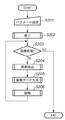
図2は、第1の実施形態における画像処理装置の処理を示すフローチャートである。まず、ステップS201において、不図示のCPUが各処理に必要なパラメータの設定を行う。ここで、設定するパラメータは、画像の縮小率、ブロックサイズ、ウインドウサイズ、閾値であり、入力画像及び除去すべきノイズの性質により決定する。また、パラメータは入力画像を解析することによって決定しても良いし、入力画像の属性(プロパティ)や出力条件によって予め決められた値に設定しても良い。尚、パラメータを常に一定値とする場合、パラメータ設定は省略される。
【0014】
次に、ステップS202において、画像縮小部101が入力画像を所定の縮小率で縮小する。この縮小処理を行うことにより、後述する低周波ノイズ除去のための画素数(ウインドウサイズ)の削減を行う。尚、この縮小率を小さくする(出力サイズを小さくする)と、後段のウインドウサイズを小さくできるが、入力画素近傍の影響度が小さくなるため、入力画素との差分が大きくなり、置換される画素が減少するだけでなく、エッジ部では置換のオン又はオフによるジャギー状の妨害が現れてしまう。また、縮小率を大きくする(出力サイズを大きくする)と、後段のウインドウサイズを大きくできるが、処理量が増加してしまう。そこで、第1の実施形態では縮小率を1/4として説明する。
【0015】
画像の縮小が終わると、ステップS203へ進み、画像の終端まで処理したか否かを判定し、処理したのであれば終了するが、処理していなければステップS204へ進み、画素抽出部102が入力画素(注目画素)位置に対応する縮小画素を中心に所定形状内(ウインドウ)の縮小画素データを抽出する。これは2次元FIRフィルタのタップ(ウインドウ)に相当し、入力画素(注目画素)位置の移動によりシフトする。尚、上述のように、縮小率を1/4としているので、縮小画素が4×4のブロックから生成した場合、入力画素が水平方向に4画素移動するとウインドウが1画素水平方向にシフトする。また、入力画素が垂直方向に4ライン移動するとウインドウが1ライン垂直方向にシフトする。つまり、入力画素が移動し、入力画素に対応する縮小画素が1画素シフトするとウインドウも1画素分シフトする。
【0016】
ここで、ウインドウサイズを4×4、縮小率を1/4とすると、元の入力画像上では16×16のウインドウに相当し、特に8×8の大きさまでの斑状ノイズの削減に効果的である。以下ではウインドウサイズを4×4として説明する。
【0017】
次に、ステップS205において、抽出されたウインドウ内の画素より、置換データを生成する。尚、この処理の詳細は後述するが、ウインドウ内平均値演算部103、領域判定部104、領域0平均値演算部105、領域1平均値演算部106、領域0差分値生成部107、領域1差分値生成部108、ウインドウ内差分値生成部109、比較部111によって行われる処理である。
【0018】
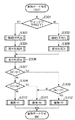
図3は、第1の実施形態における置換データ生成処理を示すフローチャートである。まずステップS301において、領域判定部104でウインドウ内の画素が領域0か領域1のどちらの領域かを判定する。具体的には、ウインドウ内平均値演算部103でウインドウ内の画素値の平均を求め、各ウインドウ内の画素をそのウインドウ平均値と比較し、ウインドウ平均値以下なら領域0とし、それ以外では領域1とする。ここで、画素が領域0であればステップS302へ進み、領域0平均値演算部105で画素の平均値を求める。また、画素が領域1であればステップS303へ進み、領域1平均値演算部106で画素の平均値を求める。そして、ステップS304又はS305において、領域0差分値生成部107又は領域1差分値生成部108で、各領域の平均値と入力画素値との差分絶対値D0又はD1を求める。
【0019】
次に、ステップS306において、ウインドウ内差分値生成部109で上述のウインドウ平均値と入力画素値との差分絶対値Dwを求める。そして、ステップS307〜S309において、比較部111で各領域の平均値と入力画素値との差分絶対値D0、D1と、ウインドウ平均値と入力画素値との差分絶対値Dwとを各々比較する。その結果、最小の差分絶対値(最小差分絶対値D)となる平均値を置換データとする(ステップS310〜S312)。
【0020】
つまり、領域0の差分絶対値D0が最小であれば、領域0平均値演算部105で求めた平均値A0を置換データとする。また同様に、領域1の差分絶対値D1が最小であれば、領域1平均値演算部106で求めた平均値A1を置換データとし、ウインドウ内差分値Dwが最小であれば、ウインドウ内平均値演算部103で求めた平均値Awを置換データとする。
【0021】
ここで図2に戻り、ステップS206において、比較部111及び画素置換部112で、上述の最小差分絶対値Dに対して所定の条件が成立すると、入力画素値を生成された置換データで置き換えて出力し、また所定の条件が不成立のときは入力画素値をそのまま出力する。以上の処理を入力画像の終端まで繰り返すと(ステップS203のYES)、この処理を終了する。
【0022】
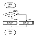
図4は、第1の実施形態における置換処理を示すフローチャートである。まずステップS401において、比較部111で最小差分絶対値Dと閾値Th1とを比較し、最小差分絶対値Dが閾値Th1未満であればステップS402へ進み、画素置換部112で置換データを出力する。また最小差分絶対値Dが閾値Th1以上であればステップS403へ進み、入力画素値を出力する。
【0023】
上述した一連の処理により、求めた差分絶対値の内、閾値Th1未満で最小となる差分絶対値の平均値を置換データとして入力画素を置換することで、ノイズを除去することができる。
【0024】
上述したように、例えば8×8の大きさまでの斑状ノイズを削減する際に、縮小画像を用いない場合、16×16のウインドウが必要になり、水平方向の画素数をWとすると、必要なラインメモリの容量は15Wとなるが、第1の実施形態では、1/4縮小画像を用いることで、必要なラインメモリの容量は3ライン×(1/4)W=(3/4)Wとなり1/20に削減される。
【0025】
このように、第1の実施形態によれば、平均値と入力画素値を比較することでノイズと有意信号の分離を図り、縮小画像より置換データを生成することにより、より低い周波数成分までノイズ除去効果を有効にし、領域別の平均値を用いることにより、エッジ付近における置換画素を増加させ、ノイズ除去効果が有効となる範囲を拡大させることができると共に簡単な操作で弊害も少なく、より効果的なノイズ除去効果を得ることができる。
【0026】
尚、第1の実施形態では、領域の判定にウインドウ内の画素平均を用いたが、本発明はこれに限らず、例えばウインドウ内の画素を大きい順に並べた時の中央に位置する画素の値やウインドウ内の画素レンジの中央値としても良い。また、置換画素候補も各領域の平均値の代わりに最大値の次に大きい数や最小値の次に小さい数としても良い。
【0027】
[第2の実施形態]
次に、図面を参照しながら本発明に係る第2の実施形態を詳細に説明する。
【0028】
第2の実施形態では、2つの領域の平均値の差分が小さいウインドウにおいては置換データをウインドウ内平均値とするものである。
【0029】
図5は、第2の実施形態における画像処理装置の構成を示すブロック図である。図5において、501〜506、507は第1の実施形態における図1に示した101〜106、110の各処理と同様であり、その説明は省略する。508は平均値演算部、509、513、514は比較部、710、711は選択部、712は減算部、715は差分値生成部、716は画素置換部である。ここでは、第1の実施形態と異なる部分のみ説明する。
【0030】
平均値演算部508では、領域0の平均値と領域1の平均値との平均値を演算する。即ち、領域0の平均値をA0、領域1の平均値をA1とすると、領域0と領域1の平均値A01はA01=(A0+A1)/2となる。この領域0と領域1の平均値A01は比較部509で入力画素値Piと比較される。ここで、入力画素値Piが領域0と領域1の平均値A01未満であれば、選択部510は領域0の平均値A0を出力し、それ以外では領域1の平均値A1を出力する。即ち、選択部510からは入力画素値Piに近い方の平均値が選択される。また、減算部512では、領域0と領域1の平均値の差分D10が求めら、比較部513で閾値Th2と比較され、差分D10が閾値Th2以下であれば、選択部511はウインドウ内平均値Awを出力し、それ以外では選択部510の出力、即ち、入力画素値Piに近い方の平均値を出力する。つまり、選択部511の出力が置換データとなる。ここで、A1>A0であるので、領域0と領域1の平均値の差分D10はD10=A1−A0となる。
【0031】
差分値生成部515は入力画素値Piと選択部511の出力(置換データ)との差分絶対値Dtを生成する。この差分絶対値Dtは比較部514で閾値Th1と比較され、差分絶対値Dtが閾値Th1未満の時のみ画素置換部516で入力画素値Piを選択部511の出力(置換データ)で置換する。尚、それ以外では、画素置換部516からは入力画素値Piがそのまま出力される。
【0032】
次に、第2の実施形態における画像処理装置の処理について説明する。第2の実施形態では、第1の実施形態における図2のS201〜S204は同様であり、ここでは置換データ生成処理(S205)及び置換処理(S206)について詳細に説明する。
【0033】
図6は、第2の実施形態における置換データ生成処理を示すフローチャートである。まずステップS601において、領域判定部504でウインドウ内の画素が領域0か領域1のどちらの領域かを判定する。具体的には、ウインドウ内平均値演算部503でウインドウ内の画素値の平均を求め、各ウインドウ内の画素をそのウインドウ平均値と比較し、ウインドウ平均値以下なら領域0とし、それ以外では領域1とする。ここで、画素が領域0であればステップS602へ進み、領域0平均値演算部505で画素の平均値を求める。また、画素が領域1であればステップS603へ進み、領域1平均値演算部506で画素の平均値を求める。
【0034】
次に、ステップS604において、減算部512で2つの領域の平均値の差分値を求め、比較部513で閾値Th2と比較する。ここで、求めた差分値が閾値Th2以下であればステップS608へ進み、置換データはウインドウ内平均値Awとなる。即ち、選択部511でウインドウ内平均値Awを置換データとして出力する。また、求めた差分値が閾値Th2より大きければステップS605へ進み、平均値演算部508で2つの領域平均値の平均値を求め、比較部509で入力画素値Piと比較する。尚、ステップS605では2つの領域平均の平均値との比較の代わりに、2つの領域平均値の加算値と入力画素データPiを2倍(1ビット左シフト)した値との比較を行っている。
【0035】
ここで、入力画素データPiが2つの領域平均値の平均値未満ならステップS606へ進み、置換データは領域0平均値A0となるが、それ以外ではステップS607へ進み、置換データは領域1平均値A1となる。即ち、入力画素データPiがどちらの領域平均値に近いか否かを判定し、選択部510で近い方の領域平均値を置換データとして出力するものである。
【0036】
図7は、第2の実施形態における置換処理を示すフローチャートである。まずステップS701において、入力画素値と選択部511の出力である置換データとの差分値Dを求め、ステップS702において、比較部514で閾値Th1と比較する。ここで、差分値Dが閾値Th1未満であればステップS703へ進み、画素置換部516で置換データを出力する。また差分値Dが閾値Th1以上であればステップS704へ進み、入力画素値を出力する。
【0037】
このように、第2の実施形態によれば、2つの領域の平均値の差分が小さいウインドウにおいては置換データをウインドウ内平均値とすることで、平坦部におけるノイズ除去効果を増加させることができ、また、処理も簡略化される。
【0038】
[第3の実施形態]
次に、図面を参照しながら本発明に係る第3の実施形態を詳細に説明する。
【0039】
第3の実施形態では、第2の実施形態で説明した置換データ生成処理において乱数生成部によって生成された乱数に応じて2つの領域の平均値を置換データとして出力するものである。
【0040】
図8は、第3の実施形態における画像処理装置の構成を示すブロック図である。図8において、801〜807、810〜812は第2の実施形態における図5に示した501〜507、514〜516の各処理と同様であり、その説明は省略する。808は乱数生成部、809は選択部である。ここでは、第2の実施形態と異なる部分のみ説明する。
【0041】
この乱数生成部808では、公知の手法によって擬似乱数を生成し、選択部809を制御して領域0の平均値或いは領域1の平均値をランダムに選択し、置換データとする。そして、差分値生成部811は、入力画素値Piと選択部809の出力(置換データ)との差分絶対値Dtを生成する。この差分絶対値Dtは比較部810で閾値Th1と比較され、差分絶対値Dtが閾値Th1未満の時のみ画素置換部812で入力画素値Piを選択部809の出力(置換データ)で置換する。また、それ以外では、画素置換部812からは入力画素値Piがそのまま出力される。
【0042】
ここで、第3の実施形態における画像処理装置の処理について説明する。尚、置換データ生成処理以外については第2の実施形態と同様であるため、その説明は省略する。
【0043】
図9は、第3の実施形態における置換データ生成処理を示すフローチャートである。まずステップS901において、領域判定部804でウインドウ内の画素が領域0か領域1のどちらの領域かを判定する。具体的には、ウインドウ内平均値演算部803でウインドウ内の画素値の平均を求め、各ウインドウ内の画素をそのウインドウ平均値と比較し、ウインドウ平均値以下なら領域0とし、それ以外では領域1とする。ここで、画素が領域0であればステップS902へ進み、領域0平均値演算部805で画素の平均値を求める。また、画素が領域1であればステップS903へ進み、領域1平均値演算部806で画素の平均値を求める。
【0044】
次に、ステップS904において、乱数生成部808で1ビットの乱数を生成し、乱数が0であればステップS905へ進み、選択部809で領域0平均値A0を置換データとして出力する。また、乱数が0でなければステップS906へ進み、領域1平均値A1を置換データとして出力する。
【0045】
このように、第3の実施形態によれば、ランダムに領域0又は領域1の平均値を選択し、置換データとすることにより、低周波ノイズが乱数により高周波側に変調されるため、表示系や視覚のMTFによるノイズ除去効果が得られる。また、更に処理も簡略化される。また、上述の乱数出力の0の連続数及び1の連続数を制限することにより、乱数の周波数特性が高域側にシフトするので、より良好なノイズ除去効果が得られる。
【0046】
[第4の実施形態]
次に、図面を参照しながら本発明に係る第4の実施形態を詳細に説明する。
【0047】
第4の実施形態では、乱数生成部によって生成された乱数に応じてウインドウ内の画素をランダムに選択し、置換データとして出力するものである。
【0048】
図10は、第4の実施形態における画像処理装置の構成を示すブロック図である。図10において、1001、1002、1003は第1乃至第3の実施形態における画像削減部、画素抽出部、タイミング調整部と同様であり、1006〜1008は第2及び第3の実施形態における比較部、差分値生成部、画素置換部と同様であり、その説明は省略する。1004は乱数発生部、1005は画素選択部である。ここでは、前述した実施形態と異なる部分のみ説明する。
【0049】
乱数生成部1004は、第3の実施形態と同様に、公知の手法により擬似乱数を生成し、画素選択部1005を制御してウインドウ内の画素をランダムに選択し、置換データとする。そして、第2及び第3の実施形態と同様に、差分値生成部1007は、入力画素値Piと画素選択部1005の出力(置換データ)との差分絶対値Dtを生成する。この差分絶対値Dtは比較部1006で閾値Th1と比較され、差分絶対値Dtが閾値Th1未満の時のみ画素置換部1008で入力画素データPiを画素選択部1005の出力(置換データ)で置換する。また、それ以外では、画素置換部1008からは入力画素値Piがそのまま出力される。
【0050】
尚、第4の実施形態におけるウインドウサイズを4×4とすると、ウインドウ内の画素数は16であるから乱数の桁数は4ビットとなる。
【0051】
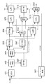
図11は、9ビットのM系列擬似ランダム符号生成回路の一構成例を示す図である。図11において、1101はシフトレジスタ、1102はEXOR回路である。このM系列擬似ランダム符号生成回路では、予めシフトレジスタ1101に0以外の値をロードしておき、シフトレジスタの原始多項式に対応するビットをEXORした結果をビット0に入力し、左シフトすることで次の乱数を得る。第4の実施形態では、シフトレジスタ1101の段数が9段なので、9次の原始多項式X9+X4+1を用いている。よって、シフトレジスタ1101のビット8とビット3をEXOR回路1302でEXORした結果をビット0の入力とし、次のクロックで左シフトする。本構成により1〜511の乱数が、511周期で生成される。
【0052】
ここで、乱数生成部1004のレンジは0〜15であるので、シフトレジスタ1101の任意の4ビットを用いることにより、511周期の0〜15の乱数を得ることができる。また、乱数生成手段はこの方法に限らず、公知の手法により擬似乱数を生成しても良い。
【0053】
また、ウインドウ内の横の位置及び縦の位置をそれぞれ擬似乱数によって発生させ、置換データとする画素を決定することもできる。
【0054】
また、擬似乱数の発生確率は一様な確率分布でも良く、ウインドウ内において入力画素に対応する画素からの距離に依存した確率分布でも良い。例えば、置換による低周波ノイズ除去効果を高くするために、入力画素に対応する画素から遠い位置にある画素程高い発生確率を与えるようにしても良い。
【0055】
また、上述した閾値との比較で、置換がされなかった場合、置換されるまで又は所定回数に達するまで、注目しているウインドウ内から別の新たな置換データを生成し、閾値と比較することで、置き換えの確率を高くすることができる。
【0056】
このように、第4の実施形態によれば、ウインドウ内の画素をランダムに選択して置換データとするので、簡単な構成であるにもかかわらず、低周波ノイズが発生乱数により高周波側に変調されるため、表示系や視覚のMTFによる良好なノイズ除去効果が得られる。また、乱数出力を入力画素が更新されるに従って反転或いは非反転させることにより、乱数の周波数特性が高域側にシフトするので、より良好なノイズ除去効果が得られる。
【0057】
[第5の実施形態]
次に、図面を参照しながら本発明に係る第5の実施形態を詳細に説明する。
【0058】
第5の実施形態では、入力画像を複数のカテゴリに分類し、各カテゴリに応じた置換データを生成するものである。
【0059】
図12は、第5の実施形態における画像処理装置の構成を示すブロック図である。図12において、1201〜1203、1207〜1209は第4の実施形態における図10に示した1001〜1003、1006〜1008の各処理と同様であり、その説明は省略する。1204はカテゴライズ部、1205は置換データ生成部、1206は置換データ選択部である。ここでは、第4の実施形態と異なる部分のみ説明する。
【0060】
カテゴライズ部1204は入力画像を複数のカテゴリに分類する。また、置換データ生成部1205は、第1乃至第4の実施形態において説明したような複数のアルゴリズム又は複数の異なる閾値によってノイズ除去のための置換データを生成する。そして、置換データ選択部1206は、カテゴリに従ってカテゴリに適した置換データを選択する。以下、第4の実施形態と同様の判定を行い、入力画素を置換してノイズを除去する。
【0061】
ここでのカテゴリは、例えば置換処理をした場合に弊害となる部分や、低周波ノイズが目立つ部分、高周波ノイズが目立つ部分、どちらのノイズも目立つ部分などを基準にして分類される。特に、第1乃至第4の実施形態では、弊害の見え方が異なっており、入力画像に対する相性が存在する。
【0062】
例えば、布のように細かなテクスチャが多い部分では、平均化処理を行わない方が見た目は良いので、第4の実施形態が向いている。また、暗部においては、平均化した方が見た目は良いので、第2の実施形態が向いている。更に、入力画素の色域によってもノイズの見え方が異なる。また、平坦部と認識されるレベル差も異なる。よって、第2の実施形態における閾値Th2の最適値も異なる。
【0063】
このように、第5の実施形態によれば、複数のアルゴリズム(閾値制御を含む)によって置換データを生成し、カテゴリに合せた置換データを選択して入力画素を置換するので、弊害が少なく良好なノイズ除去効果が得られる。
【0064】
[第6の実施形態]
次に、図面を参照しながら本発明に係る第6の実施形態を詳細に説明する。
【0065】
第6の実施形態では、第5の実施形態に更にカテゴリに従って複数の閾値から閾値を選択する閾値選択部を加えたものである。
【0066】
図13は、第6の実施形態における画像処理装置の構成を示すブロック図である。図13において、1301〜1309は第5の実施形態における図12に示した各処理と同様であり、その説明は省略する。1310は閾値選択部である。ここでは、第5の実施形態と異なる部分のみ説明する。
【0067】
カテゴライズ部1304は、入力画像を複数のカテゴリに分類する。閾値選択部1310は、分類されたカテゴリに従ってカテゴリに適した閾値Th1を選択する。以下、第5の実施形態と同様の判定を行い、入力画素を置換してノイズを除去する。
【0068】
ここでのカテゴリは、例えば置換処理をした場合に弊害の見え方を基準にして分類される。つまり、弊害が目立たない部分では閾値を大きくすることでノイズ除去効果を強化し、弊害が目立つ部分では閾値を小さくすることで弊害を目立たなくするのである。
【0069】
更に、AGC(Auto Gain Control)などにより、入力ゲインが異なる場合、ノイズの振幅は異なるので、入力ゲインによっても閾値Th1を変更することが望ましい。
【0070】
尚、第6の実施形態では、複数の置換生成部と閾値とを対応付けて説明したが、これに限らず、複数の置換生成部と閾値の数が異なっても良い。例えば、1つの置換生成部より置換データを生成しても良い。この場合は、置換データ選択部1306は省略される。
【0071】
このように、第6の実施形態によれば、カテゴリに応じた閾値を選択して入力画素を置換するので、弊害が少なく良好なノイズ除去効果が得られる。
【0072】
[他の実施形態]
前述した各実施形態の機能を実現するソフトウェアのプログラムコードを記録した記録媒体を、システム或いは装置に供給し、そのシステム或いは装置のコンピュータ(CPU又はMPU)が記録媒体に格納されたプログラムコードを読み出し実行することによっても、本発明の目的が達成されることは言うまでもない。
【0073】
この場合、記録媒体から読み出されたプログラムコード自体が本発明の新規な機能を実現することになり、そのプログラムコードを記録した記録媒体は本発明を構成することになる。
【0074】
プログラムコードを供給するための記録媒体としては、例えば、フレキシブルディスク、ハードディスク、光ディスク、光磁気ディスク、CD−ROM,CD−R、磁気テープ、不揮発性のメモリカード、ROMなどを用いることができる。
【0075】
また、コンピュータが読み出したプログラムコードを実行することによって、前述した実施形態の機能が実現される他、そのプログラムコードの指示に基づき、コンピュータ上で稼動しているOSなどが実際の処理の一部又は全部を行い、その処理によっても前述した実施形態の機能が実現され得る。
【0076】
更に、記録媒体から読み出されたプログラムコードがコンピュータに挿入された機能拡張ボードやコンピュータに接続された機能拡張ユニットに備わるメモリに書き込まれた後、そのプログラムコードの指示に基づき、その機能拡張ボードや機能拡張ユニットに備わるCPUなどが実際の処理の一部又は全部を行い、その処理によっても前述した実施形態の機能が実現され得る。
【0077】
尚、本発明は、前述した実施形態の機能を実現するソフトウェアのプログラムコードを記録した記憶媒体から、そのプログラムをパソコン通信など通信ラインを介して要求者にそのプログラムを配信する場合にも適用できることは言うまでもない。
【0078】
【発明の効果】
以上説明したように、本発明によれば、平均値と入力画素値を比較することでノイズと有意信号の分離を図り、縮小画像より置換データを生成することにより、より低い周波数成分までノイズ除去効果を有効にし、領域別平均値を用いることによって、エッジ付近における置換画素を増加させ、ノイズ除去効果が有効となる範囲を拡大させることができ、簡単な操作で弊害も少なく、より効果的なノイズ除去効果が得られる。特に、処理に必要なラインメモリの容量は大幅に削減される。
【0079】
また、2つの領域平均の差分が小さいウインドウにおいては置換データをウインドウ内平均値とすることで、平坦部におけるノイズ除去効果を増加させることができ、また、処理も簡略化される。
【0080】
また、ランダムに領域0又は領域1の平均値を選択し、置換データとすることで、低周波ノイズを乱数により高周波側に変調し、表示系や視覚のMTFによるノイズ除去効果が得られる。そして、更に処理も簡略化される。
【0081】
また、縮小画像生成によって高周波ノイズを除去した後、縮小画像のウインドウ内の画素をランダムに選択して置換データとすることで、ディティールを損なわずに良好なノイズ除去効果が得られる。
【0082】
また、閾値制御を含む複数のアルゴリズムによって置換データを生成し、カテゴリに合せた置換データを選択して入力画素を置換することで、弊害が少なく画像の特性にマッチした良好なノイズ除去効果が得られる。
【0083】
また、カテゴリに合せた閾値を選択して入力画素を置換することで、弊害がより少なく画像の特性にマッチした良好なノイズ除去効果が得られる。
【図面の簡単な説明】
【図1】第1の実施形態における画像処理装置の構成を示すブロック図である。
【図2】第1の実施形態における画像処理装置の処理を示すフローチャートである。
【図3】第1の実施形態における置換データ生成処理を示すフローチャートである。
【図4】第1の実施形態における置換処理を示すフローチャートである。
【図5】第2の実施形態における画像処理装置の構成を示すブロック図である。
【図6】第2の実施形態における置換データ生成処理を示すフローチャートである。
【図7】第2の実施形態における置換処理を示すフローチャートである。
【図8】第3の実施形態における画像処理装置の構成を示すブロック図である。
【図9】第3の実施形態における置換データ生成処理を示すフローチャートである。
【図10】第4の実施形態における画像処理装置の構成を示すブロック図である。
【図11】9ビットのM系列擬似ランダム符号生成回路の一構成例を示す図である。
【図12】第5の実施形態における画像処理装置の構成を示すブロック図である。
【図13】第6の実施形態における画像処理装置の構成を示すブロック図である。
【符号の説明】
101 画像縮小部
102 画素抽出部
103 ウインドウ内平均値演算部
104 領域判定部
105 領域0平均値演算部
106 領域1平均値演算部
107 領域0差分値生成部
108 領域1差分値生成部
109 ウインドウ内差分値生成部
110 タイミング調整部
111 比較部
112 画素置換部[0001]
BACKGROUND OF THE INVENTION
The present invention relates to a technique for reducing noise in an input multilevel image.
[0002]
[Prior art]
Conventionally, image data captured by a digital camera or image data optically read by a scanner or the like includes various noises derived from an optical sensor such as a CCD, such as high-frequency noise and relatively large patchy noise. Low frequency noise is included. In order to reduce high-frequency noise among these noises, a low-pass filter is generally used in many cases.
[0003]
Moreover, as a high frequency noise reduction process, there is also an example using a median filter process (for example, refer to Patent Document 1).
[0004]
[Patent Document 1]
JP-A-4-235472
[Problems to be solved by the invention]
However, if the various filter processes as described above are performed on all the image data, not only noise but also high-frequency components of the image are reduced, so that the image quality is deteriorated. The various filter processes as described above are mainly aimed at reducing high-frequency noise, and have no effect on the reduction of low-frequency noise such as the relatively large spotted noise.
[0005]
The present invention has been made to solve the above-described problems, and an object thereof is to reduce low-frequency noise while suppressing adverse effects such as a decrease in resolution.
[0006]
[Means for Solving the Problems]
In order to achieve the above object, an image processing method according to the present invention includes a step of reducing an input image at a predetermined magnification to obtain a reduced image, and a window in a window of a predetermined size corresponding to the position of an input pixel from the reduced image. Extracting pixels; and An average value of the extracted pixels is obtained, a determination is made as to which of the two regions the input pixel is, a representative value is obtained for each of the determined regions, and the average value, the two representative values, and the input pixel Each difference value is obtained, and the average value and the two representative values are selected as replacement data, with the smallest difference value. A step of obtaining a difference value between the replacement data and the value of the input pixel, a step of comparing the difference value with a first threshold value, and a case where the difference value is less than the first threshold value. And a step of replacing the value of the input pixel with the replacement data.
The image processing method according to the present invention also provides an input image with a predetermined magnification. Reduce with do it Shrink Obtaining an image; and Shrink Extracting a pixel in a window of a predetermined size corresponding to the position of the input pixel from the image; An average value of the extracted pixels is obtained, a determination is made as to which of the two regions each pixel is, a representative value is obtained for each determined region, and a difference between the obtained two region representative values is obtained. The difference between the two region representative values is compared with a second threshold value, and when the difference between the two region representative values is less than or equal to the second threshold value, the average value is used as replacement data, and the average of the two region representative values is Determining, comparing the average of the two area representative values with the value of the input pixel, and selecting a smaller area representative value when the value of the input pixel is less than the average of the two area representative values; When the value of the input pixel is equal to or greater than the average of the two area representative values, the larger area representative value is selected, and when the difference between the two area representative values exceeds the second threshold, the selected representative Using the value as replacement data, and A step of obtaining a difference value between replacement data and the value of the input pixel, a step of comparing the difference value with a first threshold value, and a value of the input pixel when the difference value is less than the first threshold value. And a step of replacing with the replacement data.
[0007]
DETAILED DESCRIPTION OF THE INVENTION
Hereinafter, embodiments according to the present invention will be described in detail with reference to the drawings. The embodiments described below provide disclosure to facilitate implementation by those skilled in the art of the present invention, and are only included in the technical scope of the present invention defined by the claims. Only some embodiments.
[0008]
Therefore, it will be apparent to those skilled in the art that even embodiments that are not directly described in the specification are included in the technical scope of the present invention as long as they share the same technical idea.
[0009]
Although a plurality of embodiments are described for convenience, those skilled in the art can easily understand that these are not only individually established as inventions, but of course, the invention can also be realized by appropriately combining a plurality of embodiments. I can do it.
[0010]
[First Embodiment]
FIG. 1 is a block diagram illustrating a configuration of an image processing apparatus according to the first embodiment. In FIG. 1,
[0011]
[0012]
Next, a description will be given of a process in which an input image is blocked and a pixel of interest in a block of interest is replaced based on a predetermined condition in the image processing apparatus having the above-described configuration.
[0013]
FIG. 2 is a flowchart illustrating processing of the image processing apparatus according to the first embodiment. First, in step S201, a CPU (not shown) sets parameters necessary for each process. Here, the parameters to be set are the image reduction ratio, block size, window size, and threshold value, and are determined according to the nature of the input image and noise to be removed. The parameter may be determined by analyzing the input image, or may be set to a value determined in advance according to the attribute (property) of the input image and the output condition. If the parameter is always a constant value, parameter setting is omitted.
[0014]
Next, in step S202, the
[0015]
When the reduction of the image is completed, the process proceeds to step S203, where it is determined whether or not the processing has been completed up to the end of the image. If it has been processed, the process ends. If not, the process proceeds to step S204 where the
[0016]
Here, if the window size is 4 × 4 and the reduction ratio is 1/4, it corresponds to a 16 × 16 window on the original input image, and is particularly effective in reducing spotted noise up to a size of 8 × 8. is there. In the following description, the window size is assumed to be 4 × 4.
[0017]
Next, in step S205, replacement data is generated from the extracted pixels in the window. Although details of this processing will be described later, the in-window average
[0018]
FIG. 3 is a flowchart showing replacement data generation processing in the first embodiment. First, in step S301, the
[0019]
In step S306, the in-window difference
[0020]
That is, if the difference absolute value D0 of the area 0 is minimum, the average value A0 obtained by the area 0 average
[0021]
Returning to FIG. 2, in step S206, when the
[0022]
FIG. 4 is a flowchart showing the replacement process in the first embodiment. First, in step S401, the
[0023]
Through the series of processes described above, noise can be removed by replacing the input pixel with the average value of the absolute difference value that is the minimum difference less than the threshold Th1 among the obtained absolute difference values as replacement data.
[0024]
As described above, for example, when reducing patchy noise up to a size of 8 × 8, if a reduced image is not used, a 16 × 16 window is required, and it is necessary if the number of pixels in the horizontal direction is W. The capacity of the line memory is 15 W, but in the first embodiment, the required line memory capacity is 3 lines × (1/4) W = (3/4) W by using a 1/4 reduced image. And reduced to 1/20.
[0025]
As described above, according to the first embodiment, noise and a significant signal are separated by comparing the average value and the input pixel value, and by generating replacement data from the reduced image, noise can be reduced to a lower frequency component. By making the removal effect effective and using the average value for each area, the number of replacement pixels near the edge can be increased, the range in which the noise removal effect is effective can be expanded, and the simple operation has fewer harmful effects and is more effective. Noise removal effect can be obtained.
[0026]
In the first embodiment, the pixel average in the window is used for the region determination. However, the present invention is not limited to this. For example, the value of the pixel located at the center when the pixels in the window are arranged in descending order. Or the median pixel range in the window. Also, the replacement pixel candidates may be the next largest number after the maximum value or the next smallest number after the minimum value instead of the average value of each region.
[0027]
[Second Embodiment]
Next, a second embodiment according to the present invention will be described in detail with reference to the drawings.
[0028]
In the second embodiment, in a window where the difference between the average values of the two areas is small, the replacement data is used as the average value in the window.
[0029]
FIG. 5 is a block diagram illustrating a configuration of the image processing apparatus according to the second embodiment. 5,
[0030]
The average
[0031]
The difference
[0032]
Next, processing of the image processing apparatus in the second embodiment will be described. In the second embodiment, S201 to S204 in FIG. 2 in the first embodiment are the same, and here, the replacement data generation process (S205) and the replacement process (S206) will be described in detail.
[0033]
FIG. 6 is a flowchart showing replacement data generation processing in the second embodiment. First, in step S601, the
[0034]
Next, in step S604, the
[0035]
If the input pixel data Pi is less than the average value of the two area average values, the process proceeds to step S606, and the replacement data is the area 0 average value A0. Otherwise, the process proceeds to step S607, and the replacement data is the
[0036]
FIG. 7 is a flowchart showing replacement processing in the second embodiment. First, in step S701, a difference value D between the input pixel value and the replacement data that is the output of the
[0037]
As described above, according to the second embodiment, in a window where the difference between the average values of the two regions is small, the replacement data is set to the average value in the window, so that the noise removal effect in the flat portion can be increased. In addition, the processing is simplified.
[0038]
[Third Embodiment]
Next, a third embodiment according to the present invention will be described in detail with reference to the drawings.
[0039]
In the third embodiment, an average value of two regions is output as replacement data in accordance with the random number generated by the random number generation unit in the replacement data generation process described in the second embodiment.
[0040]
FIG. 8 is a block diagram illustrating a configuration of an image processing apparatus according to the third embodiment. 8,
[0041]
This random
[0042]
Here, processing of the image processing apparatus in the third embodiment will be described. Since the processing other than the replacement data generation processing is the same as that of the second embodiment, description thereof is omitted.
[0043]
FIG. 9 is a flowchart showing replacement data generation processing in the third embodiment. First, in step S901, the
[0044]
In step S904, the random
[0045]
As described above, according to the third embodiment, since the low frequency noise is modulated to the high frequency side by the random number by randomly selecting the average value of the region 0 or the
[0046]
[Fourth Embodiment]
Next, a fourth embodiment according to the present invention will be described in detail with reference to the drawings.
[0047]
In the fourth embodiment, the pixels in the window are selected at random according to the random number generated by the random number generation unit, and output as replacement data.
[0048]
FIG. 10 is a block diagram illustrating a configuration of an image processing apparatus according to the fourth embodiment. In FIG. 10,
[0049]
Similar to the third embodiment, the random
[0050]
If the window size in the fourth embodiment is 4 × 4, the number of pixels in the window is 16, so the number of random digits is 4 bits.
[0051]
FIG. 11 is a diagram illustrating a configuration example of a 9-bit M-sequence pseudo-random code generation circuit. In FIG. 11,
[0052]
Here, since the range of the random
[0053]
In addition, the horizontal position and the vertical position in the window can be generated by pseudo random numbers, respectively, and the pixel to be replaced data can be determined.
[0054]
Further, the generation probability of the pseudo random number may be a uniform probability distribution, or may be a probability distribution depending on the distance from the pixel corresponding to the input pixel in the window. For example, in order to increase the low-frequency noise removal effect by replacement, a higher probability of occurrence may be given to a pixel farther from the pixel corresponding to the input pixel.
[0055]
In addition, if the replacement is not performed in the comparison with the threshold value described above, another new replacement data is generated from the window of interest until the replacement or the predetermined number of times is reached, and is compared with the threshold value. Thus, the probability of replacement can be increased.
[0056]
As described above, according to the fourth embodiment, since the pixels in the window are selected at random and used as replacement data, low-frequency noise is modulated to the high-frequency side by the generated random number despite the simple configuration. Therefore, a good noise removal effect by the display system or visual MTF can be obtained. Further, by inverting or non-inverting the random number output as the input pixel is updated, the frequency characteristic of the random number is shifted to the high frequency side, so that a better noise removal effect can be obtained.
[0057]
[Fifth Embodiment]
Next, a fifth embodiment according to the present invention will be described in detail with reference to the drawings.
[0058]
In the fifth embodiment, an input image is classified into a plurality of categories, and replacement data corresponding to each category is generated.
[0059]
FIG. 12 is a block diagram illustrating a configuration of an image processing apparatus according to the fifth embodiment. In FIG. 12,
[0060]
The
[0061]
The categories here are classified on the basis of, for example, a part that is harmful when the replacement process is performed, a part where low-frequency noise is conspicuous, a part where high-frequency noise is conspicuous, and a part where both noises are conspicuous. In particular, in the first to fourth embodiments, the appearance of harmful effects is different, and compatibility with the input image exists.
[0062]
For example, in a portion with many fine textures such as cloth, it is better to perform the averaging process, so the fourth embodiment is suitable. Also, in the dark part, the second embodiment is suitable because it looks better when averaged. Furthermore, the appearance of noise varies depending on the color gamut of the input pixel. Moreover, the level difference recognized as a flat part is also different. Therefore, the optimum value of the threshold Th2 in the second embodiment is also different.
[0063]
As described above, according to the fifth embodiment, replacement data is generated by a plurality of algorithms (including threshold control), and replacement data matching the category is selected to replace the input pixel. Noise removal effect can be obtained.
[0064]
[Sixth Embodiment]
Next, a sixth embodiment according to the present invention will be described in detail with reference to the drawings.
[0065]
In the sixth embodiment, a threshold selection unit for selecting a threshold from a plurality of thresholds according to the category is added to the fifth embodiment.
[0066]
FIG. 13 is a block diagram illustrating a configuration of an image processing apparatus according to the sixth embodiment. In FIG. 13,
[0067]
The
[0068]
The categories here are classified on the basis of how harmful effects appear when, for example, replacement processing is performed. That is, the noise removal effect is strengthened by increasing the threshold value in a portion where the harmful effect is not noticeable, and the bad effect is made inconspicuous by reducing the threshold value in a portion where the harmful effect is noticeable.
[0069]
Further, when the input gain is different due to AGC (Auto Gain Control) or the like, the amplitude of the noise is different, so it is desirable to change the threshold Th1 also by the input gain.
[0070]
In the sixth embodiment, a plurality of replacement generation units and threshold values are associated with each other. However, the present invention is not limited to this, and the number of replacement generation units and the number of threshold values may be different. For example, replacement data may be generated from one replacement generation unit. In this case, the replacement
[0071]
As described above, according to the sixth embodiment, the threshold value corresponding to the category is selected and the input pixel is replaced, so that a good noise removal effect with less harmful effects can be obtained.
[0072]
[Other embodiments]
A recording medium in which a program code of software that realizes the functions of the above-described embodiments is recorded is supplied to the system or apparatus, and the computer (CPU or MPU) of the system or apparatus reads the program code stored in the recording medium. It goes without saying that the object of the present invention can also be achieved by executing.
[0073]
In this case, the program code itself read from the recording medium realizes the novel function of the present invention, and the recording medium on which the program code is recorded constitutes the present invention.
[0074]
As a recording medium for supplying the program code, for example, a flexible disk, a hard disk, an optical disk, a magneto-optical disk, a CD-ROM, a CD-R, a magnetic tape, a nonvolatile memory card, a ROM, or the like can be used.
[0075]
In addition, the functions of the above-described embodiments are realized by executing the program code read by the computer, and the OS running on the computer is part of the actual processing based on the instruction of the program code. Alternatively, the functions of the above-described embodiment can be realized by performing all of the processes and performing the processing.
[0076]
Further, after the program code read from the recording medium is written in a memory provided in a function expansion board inserted into the computer or a function expansion unit connected to the computer, the function expansion board is based on the instruction of the program code. The CPU of the function expansion unit or the like performs part or all of the actual processing, and the functions of the above-described embodiments can also be realized by the processing.
[0077]
The present invention can also be applied to a case where the program is distributed to a requester via a communication line such as personal computer communication from a storage medium in which a program code of software realizing the functions of the above-described embodiments is recorded. Needless to say.
[0078]
【The invention's effect】
As described above, according to the present invention, noise and significant signals are separated by comparing the average value and the input pixel value, and noise is removed to lower frequency components by generating replacement data from the reduced image. By making the effect effective and using the average value for each area, the number of replacement pixels near the edge can be increased, and the range in which the noise removal effect is effective can be expanded. Noise removal effect can be obtained. In particular, the capacity of the line memory required for processing is greatly reduced.
[0079]
Further, in a window where the difference between the two area averages is small, the replacement data is set to the average value in the window, so that the noise removal effect in the flat portion can be increased, and the processing is simplified.
[0080]
In addition, by selecting an average value of region 0 or
[0081]
In addition, after removing high-frequency noise by generating a reduced image, pixels in the reduced image window are randomly selected and used as replacement data, so that a good noise removal effect can be obtained without losing detail.
[0082]
In addition, by generating replacement data using multiple algorithms including threshold control and selecting replacement data that matches the category and replacing the input pixels, a good noise reduction effect that matches the characteristics of the image is obtained. It is done.
[0083]
Also, by replacing the input pixel by selecting a threshold value that matches the category, a good noise removal effect that has less adverse effects and matches the characteristics of the image can be obtained.
[Brief description of the drawings]
FIG. 1 is a block diagram illustrating a configuration of an image processing apparatus according to a first embodiment.
FIG. 2 is a flowchart illustrating processing of the image processing apparatus according to the first embodiment.
FIG. 3 is a flowchart showing replacement data generation processing in the first embodiment.
FIG. 4 is a flowchart showing replacement processing in the first embodiment.
FIG. 5 is a block diagram illustrating a configuration of an image processing apparatus according to a second embodiment.
FIG. 6 is a flowchart showing replacement data generation processing in the second embodiment.
FIG. 7 is a flowchart showing replacement processing in the second embodiment.
FIG. 8 is a block diagram illustrating a configuration of an image processing apparatus according to a third embodiment.
FIG. 9 is a flowchart showing replacement data generation processing in the third embodiment.
FIG. 10 is a block diagram illustrating a configuration of an image processing apparatus according to a fourth embodiment.
FIG. 11 is a diagram illustrating a configuration example of a 9-bit M-sequence pseudo-random code generation circuit;
FIG. 12 is a block diagram illustrating a configuration of an image processing apparatus according to a fifth embodiment.
FIG. 13 is a block diagram illustrating a configuration of an image processing apparatus according to a sixth embodiment.
[Explanation of symbols]
101 Image reduction unit
102 pixel extraction unit
103 Average value calculator in window
104 Area determination unit
105 Area 0 average value calculator
106
107 area 0 difference value generation unit
108
109 In-window difference value generator
110 Timing adjustment unit
111 comparator
112 Pixel replacement unit
Claims (14)
前記縮小画像より入力画素の位置に対応する所定サイズのウインドウ内の画素を抽出する工程と、
前記抽出した画素の平均値を求め、前記入力画素が2つの領域の何れの領域かを判定し、判定された領域毎に代表値を求め、前記平均値及び2つの代表値と前記入力画素の値との差分値を各々求め、前記平均値及び2つの代表値の内、差分値が最小となるものを置換データとして選択する工程と、
前記置換データと前記入力画素の値との差分値を求める工程と、
前記差分値を第1の閾値と比較する工程と、
前記差分値が前記第1の閾値未満の場合に前記入力画素の値を前記置換データで置換する工程とを有することを特徴とする画像処理方法。Reducing the input image at a predetermined magnification to obtain a reduced image;
Extracting a pixel in a window of a predetermined size corresponding to the position of the input pixel from the reduced image;
An average value of the extracted pixels is obtained, a determination is made as to which of the two regions the input pixel is, a representative value is obtained for each of the determined regions, and the average value, the two representative values, and the input pixel Obtaining a difference value with each value, and selecting, as replacement data, the average value and the two representative values having the smallest difference value;
Obtaining a difference value between the replacement data and the value of the input pixel;
Comparing the difference value with a first threshold;
And a step of replacing the value of the input pixel with the replacement data when the difference value is less than the first threshold value.
前記縮小画像より入力画素の位置に対応する所定サイズのウインドウ内の画素を抽出する工程と、
前記抽出した画素の平均値を求め、各画素が2つの領域の何れの領域かを判定し、判定された領域毎に代表値を求め、求めた2つの領域代表値の差分を求め、前記2つの領域代表値の差分を第2の閾値と比較し、前記2つの領域代表値の差分が前記第2の閾値以下の場合に前記平均値を置換データとし、
前記2つの領域代表値の平均を求め、前記2つの領域代表値の平均と前記入力画素の値とを比較し、前記入力画素の値が前記2つの領域代表値の平均未満の場合に小さい方の領域代表値を選択し、前記入力画素の値が前記2つの領域代表値の平均以上の場合に大きい方の領域代表値を選択し、前記2つの領域代表値の差分が前記第2の閾値を超える場合に前記選択された代表値を置換データとする工程と、
前記置換データと前記入力画素の値との差分値を求める工程と、
前記差分値を第1の閾値と比較する工程と、
前記差分値が前記第1の閾値未満の場合に前記入力画素の値を前記置換データで置換する工程とを有することを特徴とする画像処理方法。Reducing the input image at a predetermined magnification to obtain a reduced image;
Extracting a pixel in a window of a predetermined size corresponding to the position of the input pixel from the reduced image;
An average value of the extracted pixels is obtained, a determination is made as to which of the two regions each pixel is, a representative value is obtained for each determined region, and a difference between the obtained two region representative values is obtained. A difference between the two region representative values is compared with a second threshold, and when the difference between the two region representative values is equal to or less than the second threshold, the average value is used as replacement data;
The average of the two area representative values is obtained, the average of the two area representative values is compared with the value of the input pixel, and the smaller value is obtained when the value of the input pixel is less than the average of the two area representative values. A region representative value is selected, the larger region representative value is selected when the value of the input pixel is equal to or greater than the average of the two region representative values, and the difference between the two region representative values is the second threshold value. A step of using the selected representative value as replacement data when exceeding
Obtaining a difference value between the replacement data and the value of the input pixel;
Comparing the difference value with a first threshold;
And a step of replacing the value of the input pixel with the replacement data when the difference value is less than the first threshold value.
前記縮小画像より入力画素の位置に対応する所定サイズのウインドウ内の画素を抽出する手段と、
前記抽出した画素の平均値を求め、前記入力画素が2つの領域の何れの領域かを判定し、判定された領域毎に代表値を求め、前記平均値及び2つの代表値と前記入力画素の値との差分値を各々求め、前記平均値及び2つの代表値の内、差分値が最小となるものを選択して置換データを生成する手段と、
前記置換データと前記入力画素の値との差分値を求める手段と、
前記差分値を第1の閾値と比較する手段と、
前記差分値が前記第1の閾値未満の場合に前記入力画素の値を前記置換データで置換する手段とを有することを特徴とする画像処理装置。Means for reducing the input image at a predetermined magnification to obtain a reduced image;
Means for extracting pixels in a window of a predetermined size corresponding to the position of the input pixel from the reduced image;
An average value of the extracted pixels is obtained, a determination is made as to which of the two regions the input pixel is, a representative value is obtained for each of the determined regions, and the average value, the two representative values, and the input pixel A difference value with respect to each value, and a means for generating replacement data by selecting the average value and the two representative values having the smallest difference value;
Means for obtaining a difference value between the replacement data and the value of the input pixel;
Means for comparing the difference value with a first threshold;
An image processing apparatus comprising: means for replacing the value of the input pixel with the replacement data when the difference value is less than the first threshold value.
前記縮小画像より入力画素の位置に対応する所定サイズのウインドウ内の画素を抽出する手段と、
前記抽出した画素の平均値を求め、各画素が2つの領域の何れの領域かを判定し、判定された領域毎に代表値を求め、求めた2つの領域代表値の差分を求め、前記2つの領域代表値の差分を第2の閾値と比較し、前記2つの領域代表値の差分が前記第2の閾値以下の場合に前記平均値を置換データとし、
前記2つの領域代表値の平均を求め、前記2つの領域代表値の平均と前記入力画素の値とを比較し、前記入力画素の値が前記2つの領域代表値の平均未満の場合に小さい方の領域代表値を選択し、前記入力画素の値が前記2つの領域代表値の平均以上の場合に大きい方の領域代表値を選択し、前記2つの領域代表値の差分が前記第2の閾値を超える場合に前記選択された代表値を置換データとする手段と、
前記置換データと前記入力画素の値との差分値を求める手段と、
前記差分値を第1の閾値と比較する手段と、
前記差分値が前記第1の閾値未満の場合に前記入力画素の値を前記置換データで置換する手段とを有することを特徴とする画像処理装置。Means for reducing the input image at a predetermined magnification to obtain a reduced image;
Means for extracting pixels in a window of a predetermined size corresponding to the position of the input pixel from the reduced image;
An average value of the extracted pixels is obtained, a determination is made as to which of the two regions each pixel is, a representative value is obtained for each determined region, and a difference between the obtained two region representative values is obtained. A difference between the two region representative values is compared with a second threshold, and when the difference between the two region representative values is equal to or less than the second threshold, the average value is used as replacement data;
The average of the two area representative values is obtained, the average of the two area representative values is compared with the value of the input pixel, and the smaller value is obtained when the value of the input pixel is less than the average of the two area representative values. A region representative value is selected, the larger region representative value is selected when the value of the input pixel is equal to or greater than the average of the two region representative values, and the difference between the two region representative values is the second threshold value. Means for using the selected representative value as replacement data when exceeding
Means for obtaining a difference value between the replacement data and the value of the input pixel;
Means for comparing the difference value with a first threshold;
An image processing apparatus comprising: means for replacing the value of the input pixel with the replacement data when the difference value is less than the first threshold value.
Priority Applications (2)
| Application Number | Priority Date | Filing Date | Title |
|---|---|---|---|
| JP2003085372A JP4040512B2 (en) | 2003-03-26 | 2003-03-26 | Image processing method and image processing apparatus |
| US10/809,526 US7432985B2 (en) | 2003-03-26 | 2004-03-26 | Image processing method |
Applications Claiming Priority (1)
| Application Number | Priority Date | Filing Date | Title |
|---|---|---|---|
| JP2003085372A JP4040512B2 (en) | 2003-03-26 | 2003-03-26 | Image processing method and image processing apparatus |
Publications (3)
| Publication Number | Publication Date |
|---|---|
| JP2004295361A JP2004295361A (en) | 2004-10-21 |
| JP2004295361A5 JP2004295361A5 (en) | 2005-10-20 |
| JP4040512B2 true JP4040512B2 (en) | 2008-01-30 |
Family
ID=33400311
Family Applications (1)
| Application Number | Title | Priority Date | Filing Date |
|---|---|---|---|
| JP2003085372A Expired - Fee Related JP4040512B2 (en) | 2003-03-26 | 2003-03-26 | Image processing method and image processing apparatus |
Country Status (1)
| Country | Link |
|---|---|
| JP (1) | JP4040512B2 (en) |
Families Citing this family (4)
| Publication number | Priority date | Publication date | Assignee | Title |
|---|---|---|---|---|
| JP4500521B2 (en) * | 2003-08-29 | 2010-07-14 | キヤノン株式会社 | Image processing apparatus, image processing method, computer program, and computer-readable recording medium |
| JP5493760B2 (en) * | 2009-01-19 | 2014-05-14 | 株式会社ニコン | Image processing apparatus and digital camera |
| US9619915B2 (en) | 2011-01-19 | 2017-04-11 | Adobe Systems Incorporated | Method and apparatus for converting an animated sequence of images into a document page |
| JP6822093B2 (en) * | 2016-11-21 | 2021-01-27 | 株式会社リコー | Image processing equipment, image processing system, image processing method, and image processing program |
-
2003
- 2003-03-26 JP JP2003085372A patent/JP4040512B2/en not_active Expired - Fee Related
Also Published As
| Publication number | Publication date |
|---|---|
| JP2004295361A (en) | 2004-10-21 |
Similar Documents
| Publication | Publication Date | Title |
|---|---|---|
| US7432985B2 (en) | Image processing method | |
| JP4502303B2 (en) | Image processing device | |
| JP5719148B2 (en) | Imaging apparatus, control method therefor, and program | |
| KR100750176B1 (en) | Method and System for quantization artifact removal using super precision | |
| CN107113375B (en) | Image processing apparatus, imaging apparatus, and image processing method | |
| US8494217B2 (en) | Image processing apparatus, image processing method, and program | |
| US20090245679A1 (en) | Image processing apparatus | |
| JP4847591B2 (en) | Image processing apparatus, image processing method, and image processing program | |
| CN109949199B (en) | Reversible information hiding method based on two-dimensional prediction error histogram adaptive expansion | |
| US7961977B2 (en) | Image processing apparatus, display device, and image processing method for edge-preserving smoothing | |
| US7949200B2 (en) | Image processing apparatus, display device, and image processing method | |
| JP5092536B2 (en) | Image processing apparatus and program thereof | |
| JP4040512B2 (en) | Image processing method and image processing apparatus | |
| CN101141655A (en) | Video signal picture element point chromatic value regulation means | |
| JPH1141491A (en) | Two-dimensional noise reducing circuit | |
| JP4495881B2 (en) | Block distortion remover | |
| JP2004303075A (en) | Apparatus and method for image processing | |
| CN110111270A (en) | Realize the reversible data concealing method and restoration methods of the enhancing of color image contrast | |
| JP2004303076A (en) | Image processing method and image processor | |
| JP3106831B2 (en) | Video signal processing device | |
| JP4500521B2 (en) | Image processing apparatus, image processing method, computer program, and computer-readable recording medium | |
| US8145009B2 (en) | Apparatus for removing ringing noise and apparatus for removing noise | |
| JP2006157584A (en) | Image processing method | |
| JPH0846966A (en) | Method for improving picture quality | |
| KR101462421B1 (en) | Method and apparatus of histogram equalizer for contrast enhancement of image using histogram compression |
Legal Events
| Date | Code | Title | Description |
|---|---|---|---|
| A521 | Request for written amendment filed |
Free format text: JAPANESE INTERMEDIATE CODE: A523 Effective date: 20050610 |
|
| A621 | Written request for application examination |
Free format text: JAPANESE INTERMEDIATE CODE: A621 Effective date: 20050610 |
|
| A977 | Report on retrieval |
Free format text: JAPANESE INTERMEDIATE CODE: A971007 Effective date: 20070309 |
|
| A131 | Notification of reasons for refusal |
Free format text: JAPANESE INTERMEDIATE CODE: A131 Effective date: 20070316 |
|
| A521 | Request for written amendment filed |
Free format text: JAPANESE INTERMEDIATE CODE: A523 Effective date: 20070511 |
|
| A131 | Notification of reasons for refusal |
Free format text: JAPANESE INTERMEDIATE CODE: A131 Effective date: 20070611 |
|
| A521 | Request for written amendment filed |
Free format text: JAPANESE INTERMEDIATE CODE: A523 Effective date: 20070810 |
|
| A131 | Notification of reasons for refusal |
Free format text: JAPANESE INTERMEDIATE CODE: A131 Effective date: 20070918 |
|
| A521 | Request for written amendment filed |
Free format text: JAPANESE INTERMEDIATE CODE: A523 Effective date: 20071001 |
|
| TRDD | Decision of grant or rejection written | ||
| A01 | Written decision to grant a patent or to grant a registration (utility model) |
Free format text: JAPANESE INTERMEDIATE CODE: A01 Effective date: 20071029 |
|
| A61 | First payment of annual fees (during grant procedure) |
Free format text: JAPANESE INTERMEDIATE CODE: A61 Effective date: 20071107 |
|
| FPAY | Renewal fee payment (event date is renewal date of database) |
Free format text: PAYMENT UNTIL: 20101116 Year of fee payment: 3 |
|
| R150 | Certificate of patent or registration of utility model |
Free format text: JAPANESE INTERMEDIATE CODE: R150 |
|
| FPAY | Renewal fee payment (event date is renewal date of database) |
Free format text: PAYMENT UNTIL: 20101116 Year of fee payment: 3 |
|
| FPAY | Renewal fee payment (event date is renewal date of database) |
Free format text: PAYMENT UNTIL: 20111116 Year of fee payment: 4 |
|
| FPAY | Renewal fee payment (event date is renewal date of database) |
Free format text: PAYMENT UNTIL: 20121116 Year of fee payment: 5 |
|
| FPAY | Renewal fee payment (event date is renewal date of database) |
Free format text: PAYMENT UNTIL: 20131116 Year of fee payment: 6 |
|
| LAPS | Cancellation because of no payment of annual fees |