JP4038484B2 - Synchronous phasor measuring device - Google Patents
Synchronous phasor measuring device Download PDFInfo
- Publication number
- JP4038484B2 JP4038484B2 JP2004005917A JP2004005917A JP4038484B2 JP 4038484 B2 JP4038484 B2 JP 4038484B2 JP 2004005917 A JP2004005917 A JP 2004005917A JP 2004005917 A JP2004005917 A JP 2004005917A JP 4038484 B2 JP4038484 B2 JP 4038484B2
- Authority
- JP
- Japan
- Prior art keywords
- timing
- voltage
- value
- phase angle
- estimated
- Prior art date
- Legal status (The legal status is an assumption and is not a legal conclusion. Google has not performed a legal analysis and makes no representation as to the accuracy of the status listed.)
- Expired - Fee Related
Links
Images


Classifications
-
- G—PHYSICS
- G01—MEASURING; TESTING
- G01R—MEASURING ELECTRIC VARIABLES; MEASURING MAGNETIC VARIABLES
- G01R21/00—Arrangements for measuring electric power or power factor
- G01R21/133—Arrangements for measuring electric power or power factor by using digital technique
Description
この発明は、電力系統の同期フェーザを測定する同期フェーザ測定装置に関する。 The present invention relates to a synchronized phasor measuring device that measures a synchronized phasor of a power system.
電力系統からの電気量を高精度、高速に算出する同期フェーザ測定装置は、1周期当たりN回のサンプリングタイミングで計測された電圧瞬時値Vk(k=1からN)を用いて電圧フェーザVを式(1)に基づいて求める。なお、この式(1)においてθはサンプリング角度である。そして、式(2)から同期フェーザの絶対位相角θvを求める(例えば、非特許文献1参照。)。 The synchronous phasor measuring device that calculates the amount of electricity from the power system with high accuracy and high speed uses the voltage phasor V using the instantaneous voltage value V k (k = 1 to N) measured at N sampling timings per cycle. Is obtained based on the equation (1). In Equation (1), θ is a sampling angle. Then, the absolute phase angle theta v synchronous phasor from equation (2) (e.g., see Non-Patent Document 1.).

しかし、従来の同期フェーザ測定装置は、絶対位相角θvが電圧フェーザの実数部と虚数部とから正接関数を用いて求められるので、絶対位相角θvがマイナス180度から零度、さらに零度からプラス180度へ変化する。そして、さらに絶対位相角θvがプラス180度からマイナス180度へ不連続に変化するので、連続性がなくなるとともに数値安定性が悪いという問題があった。
また、1サイクルの間の瞬時値を平均化して電圧実効値を求めているが、測定対象の周波数が基準周波数と異なる場合、正しく測定対象の電圧実効値と絶対位相角を測定することができない。特に、電力系統に事故が発生したときには周波数が大きく変動するので、測定精度が悪く、緊急に必要となる系統保護制御に同期フェーザをそのまま使用することができないという問題があった。
また、高調波成分の重畳や瞬時的な電圧の低下などによる電圧波形ノイズが絶対位相角の測定結果に影響してしまうという問題があった。
However, the conventional synchronous phasor measurement apparatus, the absolute phase angle theta v is calculated using the tangent function from the real and imaginary parts of the voltage phasors, zero absolute phase angle theta v is from 180 degrees minus, from further zero Change to plus 180 degrees. Then, further absolute phase angle theta v since changes discontinuously from the plus 180 degrees to minus 180 degrees, there is a problem of poor numerical stability with continuity is lost.
Moreover, although the instantaneous voltage value during one cycle is averaged to obtain the effective voltage value, if the frequency to be measured is different from the reference frequency, the effective voltage value and absolute phase angle of the measurement object cannot be measured correctly. . In particular, since the frequency fluctuates greatly when an accident occurs in the power system, there is a problem that the measurement accuracy is poor and the synchronized phasor cannot be used as it is for system protection control that is urgently needed.
There is also a problem that voltage waveform noise due to superposition of harmonic components or instantaneous voltage drop affects the measurement result of the absolute phase angle.
この発明の目的は、連続的な数値安定性に優れた同期フェーザの絶対位相角をノイズ等の多い電力系統で高精度・高速に測定できる同期フェーザ測定装置を提供することである。 An object of the present invention is to provide a synchronized phasor measuring apparatus capable of measuring the absolute phase angle of a synchronized phasor excellent in continuous numerical stability with high accuracy and high speed in a power system with a lot of noise.
この発明に係わる同期フェーザ測定装置は、基準波の1周期の4N(Nは正の整数)分の1の周期で電力系統の電圧を計測する電圧計測手段と、上記電圧を計測した各タイミングにおいて、自らのタイミングを含む過去の4N個のタイミングにおける計測された上記電圧から自らのタイミングにおける電圧実効値を求める電圧実効値算出手段と、上記各タイミングにおいて、自らのタイミングにおける計測された上記電圧を複素数平面上の実数部とし、該自らのタイミングに対し電気角度として90度遅れたタイミングにおける計測された上記電圧を複素数平面上の虚数部とした点に向いた電圧回転ベクトルを求め、自らのタイミングにおける求められた上記電圧回転ベクトルの先端と該自らのタイミングの1つ前のタイミングにおける上記電圧回転ベクトルの先端とを結ぶ弦の弦長を算出する弦長算出手段と、上記各タイミングにおいて、自らのタイミングを含む過去の4N個のタイミングにおける算出された上記弦長を加算し、上記弦長の加算値と上記電圧実効値平均値とに基づき、自らのタイミングにおける上記電圧回転ベクトルと自らのタイミングより基準波の1周期前のタイミングにおける上記電圧回転ベクトルとの位相角を算出する回転位相角算出手段と、上記各タイミングにおいて、算出された上記位相角から上記電力系統の周波数を算出する周波数算出手段と、上記各タイミングにおいて、自らのタイミングにおける算出された上記周波数から電圧回転ベクトルの角速度を求め、自らのタイミングを含む過去の4N個のタイミングにおける計測された上記各電圧を下記式(24)に従って展開し、自らのタイミングを含む過去の4N個のタイミングの上記係数から最小自乗法を用いて自らのタイミングにおける係数推定値を求め、上記係数推定値から下記式(25)に従って自らのタイミングにおける電圧実数瞬時推定値を推定する電圧瞬時値推定手段と、下記式(3)に従って上記各タイミングにおける同期フェーザの絶対位相角を算出する絶対位相角算出手段と、を有する。 The synchronous phasor measuring device according to the present invention includes a voltage measuring means for measuring the voltage of the power system at a period of 1 / 4N (N is a positive integer) of one period of the reference wave, and at each timing at which the voltage is measured. The voltage effective value calculation means for obtaining the voltage effective value at the own timing from the voltage measured at the past 4N timings including the own timing, and the measured voltage at the own timing at each timing. The real part on the complex plane is obtained, and a voltage rotation vector directed to the point where the measured voltage at the timing delayed by 90 degrees as the electrical angle relative to its own timing is defined as the imaginary part on the complex plane is obtained. At the timing immediately before the leading end of the voltage rotation vector determined in FIG. A chord length calculation means for calculating the chord length of the chord connecting the tip of the pressure rotation vector, and the chord lengths calculated at the past 4N timings including its own timing at each timing are added, Rotation phase for calculating a phase angle between the voltage rotation vector at its own timing and the voltage rotation vector at a timing one cycle before the reference wave from its own timing based on the added value of the length and the average voltage effective value An angle calculating means; a frequency calculating means for calculating the frequency of the power system from the phase angle calculated at each timing; and an angular velocity of a voltage rotation vector from the frequency calculated at the timing at each timing. Each of the measured voltages at the past 4N timings including its own timing. Expanding according to the expression (24), a coefficient estimated value at its own timing is obtained from the coefficients of the past 4N timings including its own timing using the least square method, and the following expression (25) is obtained from the coefficient estimated value. The voltage instantaneous value estimating means for estimating the actual voltage instantaneous number estimated value at its own timing according to the following equation , and the absolute phase angle calculating means for calculating the absolute phase angle of the synchronized phasor at each timing according to the following equation (3).
但し、vreは自らのタイミングを含む過去の4N個のタイミングにおける計測された各電圧、ωは自らのタイミングにおける求められた角速度、P1とP2は自らのタイミングにおける係数、vre_estは自らのタイミングにおける推定された電圧実数瞬時推定値、βは絶対位相角、vre_estは自らのタイミングにおける推定された電圧実数瞬時推定値、Vは自らのタイミングにおける算出された電圧実効値とする。
However, vre is each voltage measured at the past 4N timings including its own timing, ω is the angular velocity obtained at its own timing, P1 and P2 are coefficients at its own timing, and vre_est is an estimation at its own timing The estimated voltage real number instantaneous value, β is the absolute phase angle, vre_est is the estimated voltage real number instantaneous estimated value at its own timing, and V is the effective voltage value calculated at its own timing.
この発明に係わる同期フェーザ測定装置の効果は、余弦関数を使用して同期フェーザの絶対位相角が求められているので、絶対位相角が零度からプラス180度へ増加し、そこで反転して零度まで減少する。そのため、絶対位相角が常にプラス値であるとともに零度またプラス180度で連続的に変化するので、従来のような不連続な変化が見られないとともに変化量も小さいので、絶対位相角の数値安定性および連続性に優れている。 The effect of the synchronized phasor measuring device according to the present invention is that the absolute phase angle of the synchronized phasor is obtained using a cosine function, so that the absolute phase angle increases from zero degree to plus 180 degrees and then reverses to zero degree. Decrease. For this reason, the absolute phase angle is always a positive value and continuously changes at zero degrees or plus 180 degrees, so there is no discontinuous change as in the past and the amount of change is small. Excellent in continuity and continuity.
実施の形態1.
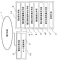
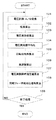
図1は、この発明の実施の形態1に係わる同期フェーザ測定装置のブロック図である。図2は、図1での同期フェーザ測定のフローチャートである。
Embodiment 1 FIG.
FIG. 1 is a block diagram of a synchronous phasor measuring apparatus according to Embodiment 1 of the present invention. FIG. 2 is a flowchart of synchronous phasor measurement in FIG.
同期フェーザ測定装置は、所定のタイミングごとに電力系統1の電圧実数瞬時値を計測する電圧計測手段2と、計測された電圧実数瞬時値をデジタルな電圧実数瞬時値に変換するA/D変換手段3と、デジタルな電圧実数瞬時値を記憶する記憶手段4と、所定のタイミングごとに隣接する電圧回転ベクトルの先端部間で形作る弦の長さを算出する弦長算出手段5と、電圧回転ベクトルから電圧実効値を算出する電圧実効値算出手段6と、算出された電圧実効値を所定の期間で平均化して電圧実効値平均値を算出する電圧実効値平均化手段7と、算出された弦の長さを所定の期間に亘って積分して回転位相角を算出する回転位相角算出手段8と、算出された回転位相角から電力系統の周波数を算出する周波数算出手段9と、デジタルな電圧実数瞬時値から最小自乗法を用いて電圧実数瞬時推定値を算出する電圧瞬時値推定手段10と、同期フェーザの絶対位相角を算出する絶対位相角算出手段11とを有する。 The synchronous phasor measuring device includes a voltage measuring unit 2 that measures a voltage real number instantaneous value of the power system 1 at a predetermined timing, and an A / D conversion unit that converts the measured voltage real number instantaneous value into a digital voltage real number instantaneous value. 3, a storage means 4 for storing a digital voltage real number instantaneous value, a chord length calculation means 5 for calculating the length of a chord formed between the tips of adjacent voltage rotation vectors at every predetermined timing, and a voltage rotation vector Voltage effective value calculating means 6 for calculating the voltage effective value from the above, voltage effective value averaging means 7 for calculating the voltage effective value average value by averaging the calculated voltage effective value over a predetermined period, and the calculated string A rotation phase angle calculation means 8 for calculating the rotation phase angle by integrating the length of the power supply over a predetermined period, a frequency calculation means 9 for calculating the frequency of the power system from the calculated rotation phase angle, and a digital voltage Real number A voltage instantaneous value estimation means 10 for calculating a voltage real instantaneous estimate using the least square method from the time value and the absolute phase angle calculating means 11 for calculating the absolute phase angle of the synchronous phasor.
電圧計測手段2とA/D変換手段3とは、デジタル電圧出力端子を有する電圧計12からなる。さらに、記憶手段4、弦長算出手段5、電圧実効値算出手段6、電圧実効値平均化手段7、回転位相角算出手段8、周波数算出手段9、電圧瞬時値推定手段10および絶対位相角算出手段11は、コンピュータ13によって構成されている。コンピュータ13は、CPU、RAM、ROMおよびインタフェース回路を有している。
また、各同期フェーザ測定装置は、GPSを用いてクロックの同期を取っている。
The voltage measuring means 2 and the A / D conversion means 3 are composed of a
Each synchronized phasor measuring device synchronizes clocks using GPS.
以下の説明において、基準波の周波数f0(Hz)は、50Hzおよび60Hzを例にして説明するが、この周波数に限らない。基準波の1周期(秒)は、周波数f0の逆数1/f0である。 In the following description, the frequency f 0 (Hz) of the reference wave will be described by taking 50 Hz and 60 Hz as an example, but is not limited to this frequency. One period (second) of the reference wave is the reciprocal 1 / f 0 of the frequency f 0 .
さらに、電圧実数瞬時値を計測する時点(以下、タイミングと称す。)は、サンプリング周期を定めることにより決まる。サンプリング周期は基準波の1周期を4N(Nは正の整数)等分できる値であればよい。後述するように、電圧回転ベクトルの先端の座標として、90度遅れた時点での電圧実数瞬時値を用いるので、90度遅れた時点がタイミングの1つである必要がある。基準波の1周期は、電気角度で表して2π(ラジアン)である。例えば、基準波の電気角度π/6、π/12、π/24、π/48などをサンプリング周期にあらかじめ設定する。 Furthermore, the time point (hereinafter referred to as “timing”) at which the voltage real number instantaneous value is measured is determined by determining the sampling period. The sampling period may be a value that can equally divide one period of the reference wave into 4N (N is a positive integer). As will be described later, since the voltage real number instantaneous value at the time when it is delayed by 90 degrees is used as the coordinates of the tip of the voltage rotation vector, it is necessary that the time when it is delayed by 90 degrees is one of the timings. One period of the reference wave is 2π (radian) expressed in electrical angle. For example, the electrical angle π / 6, π / 12, π / 24, π / 48, etc. of the reference wave is set in advance as the sampling period.
次に、電力系統の同期フェーザ測定の手順について図2を参照して説明する。この説明では、基準波の周波数f0は、50Hzとし、基準波の1周期を12等分(N=3)できるπ/6をサンプリング周期とする。刻み幅Δt(秒)は0.00166667秒となる。kは電圧計測タイミングの順番を表し、基準波の1周期では1から12となる。電圧計測タイミングk=1とk=2の間で基準波電気角度30度回転する。 Next, the procedure of the synchronized phasor measurement of the power system will be described with reference to FIG. In this description, the frequency f 0 of the reference wave is 50 Hz, and π / 6 that can divide one period of the reference wave into 12 equal parts (N = 3) is the sampling period. The step size Δt (seconds) is 0.00166667 seconds. k represents the order of voltage measurement timing, and is 1 to 12 in one cycle of the reference wave. The reference wave electrical angle is rotated by 30 degrees between the voltage measurement timings k = 1 and k = 2.
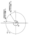
ステップ101で、電圧計測タイミング毎に、電圧計測手段2は測定対象の電力系統の電圧を計測する。電圧計測タイミングのうちの任意のタイミングをkで表す。このタイミングの1回前のタイミングを(k−1)で、次のタイミングは(k+1)で表すことができる。次に、A/D変換手段3は、アナログ信号である計測した電圧をデジタル電圧信号にA/D変換を行う。この値を記憶手段4に記憶する。図3に示すように、電力系統の電圧瞬時値v(k)を複素数平面上の原点0を中心に反時計方向に回転する電圧回転ベクトルで表現したとき、この計測した電圧は、式(4)で表される電圧実数瞬時値vre(k)である。ここで、Vは電圧実効値(ボルト)、ωは電圧回転ベクトルの角速度(ラジアン/秒)、φ0は電圧初期回転位相角(ラジアン)である。ωは、測定対象電力系統の周波数fとの間にω=2πfの関係を有する。
In
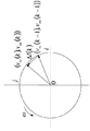
ステップ102で、弦長算出手段5は、電圧計測タイミングのそれぞれのタイミングにおいて、それぞれのタイミングで計測した電圧を複素数平面上の実数部とし、そのそれぞれのタイミングに対して電気角度として90度遅れた関係にあるタイミングで計測した電圧を複素数平面上の虚数部とした点に向いたそれぞれのタイミングの電圧回転ベクトルを求める。次に、電圧計測タイミングのそれぞれのタイミングにおいて、それぞれのタイミングで求めた電圧回転ベクトルの先端とそれぞれのタイミングの1つ前のタイミングで求められた電圧回転ベクトルの先端とを結ぶ弦の長さを算出する。図4に示すように測定対象の電力系統の所定のタイミングの電圧回転ベクトルは、基準波の1周期の間、すなわちk=0からk=12の間に複素数平面内で反時計方向に位相角Ψ(ラジアン)だけ回転する。次に、式(4)に示すように電圧瞬時値v(k)は、電圧実数瞬時値vre(k)と電圧虚数瞬時値vim(k)とからなる。この電圧虚数瞬時値vim(k)は、式(5)に示すように電圧実数瞬時値vre(k−3)に等しい。サンプリング周期をπ/6とした場合は(k−3)のタイミングで計測した電圧であるが、例えばπ/12とした場合は、(k−6)のタイミングで計測した電圧に相当する。このようにして、電圧回転ベクトルの先端の座標は、電圧実数瞬時値vre(k)、電圧虚数瞬時値vim(k)で表すことができる。電圧虚数瞬時値vim(k)は、該当する電圧実数瞬時値vre(k−3)を記憶手段4から読み出すことにより得られる。このようにして、タイミングkと(k−1)でのそれぞれの電圧回転ベクトルの座標を求めることができるので、図5に示す電圧回転ベクトルの先端を結ぶ弦の長さΔl(k)を式(6)によって求めることができる。
In
ステップ103で、電圧実効値算出手段6が、電圧計測タイミングのそれぞれのタイミングにおいて、自らのタイミングを含む、自らのタイミングから過去の12個のタイミングで計測された電圧から、基準波の1周期の間の電圧実効値V(k)を式(7)から電圧実数瞬時値vreを用いて算出する。
In
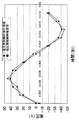
ステップ104で、電圧実効値平均化手段7が、電圧計測タイミングのそれぞれのタイミングにおいて、自らのタイミングで算出された電圧実効値と自らのタイミングに先立つ11個のタイミングで算出した電圧実効値とから基準波の1周期の間の電圧実効値Vの平均値Vave(k)を式(8)に従って算出する。自らのタイミングkでの電圧実効値の平均値Vave(k)は、タイミング(k−11)から自らのタイミングkのそれぞれで求めた電圧実効値平均値である。図6に示すように、測定対象の電力系統の周波数が基準波の周波数と異なるとき、電圧実効値は実際の電圧実効値を中心に振動している。この振動の影響を取り除くために、平均化処理を行う。
In
平均化処理の時間が長いほど、電圧実効値の精度は向上するが、測定時間の短縮のために、基準波の1周期の間、この場合はサンプリング回数12回において求めた電圧実効値を用いて平均化処理を行う。このように電圧実効値を平均化すると図6に示すように測定対象の電力系統の周波数と基準波の周波数との違いの影響を除外することができる。 The longer the averaging processing time is, the more accurate the voltage effective value is. However, in order to shorten the measurement time, the voltage effective value obtained in one sampling cycle, in this case, 12 times of sampling is used. To perform the averaging process. When the voltage effective values are averaged in this way, the influence of the difference between the frequency of the power system to be measured and the frequency of the reference wave can be excluded as shown in FIG.
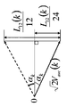
ステップ105で、回転位相角算出手段8が、電圧計測タイミングのそれぞれのタイミングにおいて、自らのタイミングを含む、自らのタイミングから過去の12個のタイミングで算出した弦長を式(9)を用いて弦長合計L12(k)を求める。 次に、回転位相角算出手段8が、電圧計測タイミングのそれぞれのタイミングにおいて、図7に示すように自らのタイミングkと自らのタイミングより1つ前のタイミング(k−1)との間の回転位相角2αkを式(10)に従って算出する。次に、電圧計測タイミングのそれぞれのタイミングにおいて、その回転位相角2αkから自らのタイミングkにおける電圧回転ベクトルと自らのタイミングkより基準波の1周期前のタイミングの電圧回転ベクトルとの間の位相角Ψ(k)を式(11)によって算出する。位相角Ψ(k)は、電圧回転ベクトルが基準波1周期で回転した電気角度である。
In
ステップ106で、周波数算出手段9は、電圧計測タイミングのそれぞれのタイミングにおいて、基準波の1周期の位相角2πと測定対象の位相角Ψ(k)とから、測定対象の電力系統の周波数f(k)を式(12)を用いて算出する。f0は基準波の周波数である。
In
ステップ107で、電圧瞬時値推定手段10が、電圧計測タイミングのそれぞれのタイミングにおいて、自らのタイミングでの電圧実数瞬時推定値を自らのタイミングを含む、自らのタイミングから過去の12個のタイミングで計測した電圧実数瞬時値vreから最小自乗法を用いて求める。電圧実数瞬時値vre(t)は、式(13)に示すように角速度と時間の積の正弦と余弦とで展開し、正弦と余弦のそれぞれの係数をP1とP2として書き直すことができる。そして、この係数P1とP2の係数推定値P1estとP2estを求め、それから電圧実数瞬時推定値を求めることができる。この係数推定値P1estとP2estの推定に最小自乗法を用いる。角速度ωは周波数f(k)より求められる。
自らのタイミングkを含む、自らのタイミングkから過去12個までのタイミングで計測した電圧を、式(13)に従い行列式表示すると、行列式(14)のように表すことができる。さらに、電圧実数瞬時値行列[v]、三角関数行列[A]はそれぞれ行列式(15)、行列式(16)で表すことができる。また、サンプリングタイミング時刻行列は、行列式(17)で表すことができる。Δtは計算刻みであり、基準波が50Hzで、1周期を12等分するときは0.0016667sであり、基準波が60Hzで、1周期を12等分するときは0.00138889sである。また、任意係数行列[P]は行列式(18)で表すことができる。
このように各行列を表すと、行列式(14)は行列式(19)として表すことができる。最小自乗法を用いて任意係数行列[P]は、行列式(20)により求めることができる。ここで転置行列[A]Tは、行列式(21)である。この任意係数行列[P]の推定された値が係数推定値P1estとP2estである。
In
Determining the voltage measured at the previous 12 timings from its own timing k including its own timing k according to the equation (13) can be expressed as the determinant (14). Furthermore, the voltage real number instantaneous value matrix [v] and the trigonometric function matrix [A] can be expressed by determinants (15) and (16), respectively. The sampling timing time matrix can be expressed by determinant (17). Δt is a calculation step, and is 0.0016667 s when the reference wave is 50 Hz and divides one cycle into twelve, and 0.00168889 s when the reference wave is 60 Hz and one cycle is divided into twelve. The arbitrary coefficient matrix [P] can be expressed by the determinant (18).
When each matrix is expressed in this way, determinant (14) can be expressed as determinant (19). The arbitrary coefficient matrix [P] can be obtained by the determinant (20) using the least square method. Here, the transposed matrix [A] T is the determinant (21). The estimated values of the arbitrary coefficient matrix [P] are the coefficient estimated values P 1est and P 2est .
このようにして任意定数行列[P]を求めることができるので、電圧実数瞬時推定値vre_est(k)は式(22)として求めることができる。図9に電圧実数瞬時値の計測値と最小自乗法を用いて推定した電圧実数瞬時推定値を示す。図9から分かるように、電圧波形ノイズなどにより、電圧実数瞬時値が変動しても、最小自乗法を用いて推定しているので、電圧波形ノイズの影響がこの電圧実数瞬時推定値に及ぶことが無くなっている。
次に、ステップ108で、絶対位相角算出手段11が、電圧計測タイミングのそれぞれのタイミングにおいて、式(8)で求めた電圧実効値平均値と式(22)で求められた電圧実数瞬時推定値とを用いて、絶対位相角β(k)を式(23)により求める。なお、電圧実数瞬時推定値の替わりにそれぞれのタイミングで計測した電圧を用いて絶対位相角を求めてもよい。また、電圧実効値平均値の替わりに式(7)で求めた電圧実効値を用いて絶対位相角を求めてもよい。
Since the arbitrary constant matrix [P] can be obtained in this way, the voltage real number instantaneous estimated value v re_est (k) can be obtained as Expression (22). FIG. 9 shows the measured value of the voltage real number instantaneous value and the voltage real number instantaneous value estimated using the least square method. As can be seen from FIG. 9, even if the voltage real number instantaneous value fluctuates due to voltage waveform noise or the like, since the estimation is performed using the least square method, the influence of the voltage waveform noise reaches this voltage real number instantaneous estimated value. Is gone.
Next, in
ステップ109で、電力系統の同期フェーザの絶対位相角の測定を終了するか否かを判定するし、さらに測定を継続するときはステップ101に戻る。
In
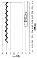
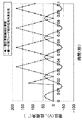
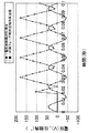
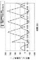
次に、基準波50Hzとし、1周期を12等分したときに、電力系統の周波数が50Hz、55Hz、45Hzとしたときの同期フェーザの絶対位相角を算出した。図10に50Hz、図11に55Hz、図12に45Hzのときの結果を示す。これら図からも分かるように電力系統の周波数が変動したときでも同期フェーザの絶対位相角を高精度に測定できている。電力系統の実際の周波数は、基準周波数を中心に最大1〜2HZの変動があるため、この発明の同期フェーザ測定装置は、高い精度かつ安定した同期フェーザを測定することができる。 Next, the absolute phase angle of the synchronized phasor was calculated when the frequency of the power system was 50 Hz, 55 Hz, and 45 Hz when the reference wave was 50 Hz and one cycle was divided into 12 equal parts. FIG. 10 shows the results at 50 Hz, FIG. 11 at 55 Hz, and FIG. 12 at 45 Hz. As can be seen from these figures, the absolute phase angle of the synchronized phasor can be measured with high accuracy even when the frequency of the power system fluctuates. Since the actual frequency of the electric power system has a maximum fluctuation of 1 to 2 HZ around the reference frequency, the synchronous phasor measuring device of the present invention can measure a highly accurate and stable synchronous phasor.
なお、計算刻み幅Δtを基準波回転電気角度30度としているが、実際測定を行う時、計算刻み幅Δtは小さいほど計測精度が高くなる。 The calculation step width Δt is set to the reference wave rotation electrical angle of 30 degrees. However, when actual measurement is performed, the smaller the calculation step width Δt, the higher the measurement accuracy.
このような電力系統の同期フェーザ測定装置は、余弦関数を使用して同期フェーザの絶対位相角が求められているので、絶対位相角が零度からプラス180度へ増加し、そこで反転して零度まで減少する。そのため、絶対位相角が常にプラス値であるとともに零度またプラス180度で連続的に変化するので、従来のような不連続な変化が見られないとともに変化量も小さいので、絶対位相角の数値安定性および連続性に優れている。 In such a synchronized phasor measuring device of the power system, the absolute phase angle of the synchronized phasor is obtained using a cosine function, so that the absolute phase angle increases from zero degree to plus 180 degrees, and then reverses to zero degree. Decrease. For this reason, the absolute phase angle is always a positive value and continuously changes at zero degrees or plus 180 degrees, so there is no discontinuous change as in the past and the amount of change is small. Excellent in continuity and continuity.
また、基準波の1周期を4N分の1の周期で計測した電圧を用いて電圧回転ベクトルを求め、一方で電圧回転ベクトルの回転位相角と基準波の回転位相角との対比から周波数を求め、他方、計測した電圧実数瞬時値から電圧実数瞬時推定値を推定するので、電力系統の1周期という短時間の間で同期フェーザが測定できる。 In addition, a voltage rotation vector is obtained by using a voltage obtained by measuring one period of the reference wave with a period of 1 / N. On the other hand, a frequency is obtained from a comparison between the rotation phase angle of the voltage rotation vector and the rotation phase angle of the reference wave. On the other hand, since the voltage real number instantaneous estimated value is estimated from the measured voltage real number instantaneous value, the synchronous phasor can be measured in a short time of one cycle of the power system.
また、電圧実効値の移動平均を求めるので、電圧実効値の誤差が小さくなり、この電圧実効値を用いて求める同期フェーザの絶対位相角の測定誤差も小さくなる。実際の電力系統に事故が発生すると周波数が大きく変化するが、その影響を最小限に抑えることができる。 Further, since the moving average of the voltage effective value is obtained, the error of the voltage effective value is reduced, and the measurement error of the absolute phase angle of the synchronous phasor obtained using this voltage effective value is also reduced. When an accident occurs in the actual power system, the frequency changes greatly, but the effect can be minimized.
また、測定された電圧から最小自乗法を用いて電圧実数瞬時推定値を推定しているので、負荷が変動したとき、または電圧が急峻に変化したとき、これらの影響を抑制し、絶対位相角の演算誤差を小さくすることができる。 In addition, since the voltage real number instantaneous estimated value is estimated from the measured voltage using the least square method, when the load fluctuates or the voltage changes sharply, these effects are suppressed and the absolute phase angle The calculation error can be reduced.
なお、この発明では、電圧を複素数平面上で回転する電圧ベクトルで表現しているが、従来の交流理論で電圧定常状態を表現するために静止ベクトル(フェ−ザ)で表現していることが異なっている。 In the present invention, the voltage is expressed by a voltage vector that rotates on a complex plane. However, in order to express a steady state of voltage in the conventional AC theory, it may be expressed by a static vector (phasor). Is different.
実施の形態2.
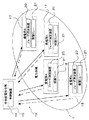
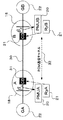
図13は、この発明の実施の形態2に係わる同期フェーザ測定装置を各発電所および変電所に備えた電力系統保護制御システムのブロック図である。
電力系統保護制御システムは、中央給電所15に備えられ、電力系統1全体を監視制御する制御装置16と、電力系統1の各所に配置されている発電所17および変電所18に備えられ、電力系統の同期フェーザを計測し、その値を制御装置16にネットワーク19を介して送信する同期フェーザ測定装置20と、発電所17および変電所18に備えられ、電力系統1を保護制御する保護リレー21とを有している。なお、同期フェーザ測定装置20は実施の形態1と同様であるので、説明は省略する。各同期フェーザ測定装置20は、GPSを用いて同期が取られている。
Embodiment 2. FIG.
FIG. 13 is a block diagram of a power system protection control system provided with a synchronized phasor measuring device according to Embodiment 2 of the present invention at each power plant and substation.
The power system protection control system is provided in the central
各発電所17および変電所18で計測された同期フェーザの絶対位相角及び周波数からなる計測情報を、変電所18および発電所17からネットワーク19を介して制御装置16に一定周期、例えば、1サイクル、50Hzの場合で20ms以内、で転送し、制御装置16が絶対位相角の差分と周波数の変動を総合的に判断し、各発電所17に発電機トリップなどの発電制限命令を、各変電所18に負荷制限あるいは系統分離命令を送信する。これら命令に従い、保護リレー21が作動して電力系統1を保護する。
Measurement information including the absolute phase angle and frequency of the synchronized phasor measured at each
このような電力系統保護制御システムは、電力系統の安定運用が図られ、大規模停電を防止することができる。 Such a power system protection control system enables stable operation of the power system and can prevent a large-scale power outage.
実施の形態3.
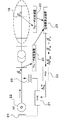
図14は、この発明の実施の形態3に係わる同期フェーザ測定装置を備えた電力系統長周期動揺制御装置のブロック図である。
電力系統長周期動揺制御装置は、発電機22の自端の同期フェーザを測定する同期フェーザ測定装置20と、発電機22から遠方に配置されている変電所18の同期フェーザを測定する同期フェーザ測定装置20と、各同期フェーザ測定装置20からの絶対位相角から位相差を算出する位相差算出装置23と、系統の長周期動揺を減衰する安定化制御装置(Power System Stabilizer)24と、変圧器25で計測された発電機22の端子電圧と位相角とを用いて発電機22の励磁回路26を制御する自動電圧調整器(Automatical Voltage Regulator)27とを有している。
FIG. 14 is a block diagram of a power system long period fluctuation control device including a synchronous phasor measurement device according to
The power system length periodic oscillation control device includes a synchronized
この電力系統長周期動揺制御装置の動作について説明する。発電機22の自端および変電所18に備えられた同期フェーザ測定装置20は、実施の形態1と同様であり、説明は省略する。
発電機22の自端での絶対位相角βMと遠方に離れた位置に配置されている変電所18での絶対位相角βNがそれぞれフェーザ測定装置20で測定される。これらの絶対位相角βMとβNとはGPSで同期が取られているので、位相差算出装置23で同時刻の位相差ΔβMNが算出される。この位相差ΔβMNが安定化制御装置24に入力され、この位相差ΔβMNに基づいて自動電圧調整器27の制御用信号Δζを算出する。自動電圧調整器27では、送電線の電圧を変圧器25で検出し、その電圧と制御用信号Δζとに基づき励磁回路26の励磁電流を制御する。このようにして、長周期の動揺が発生したときに発電機22の発電電力が制御される。
The operation of this power system long period fluctuation control device will be described. The synchronous
The
このような電力系統長周期動揺制御装置は、電力系統に発生する長周期の動揺を従来の有効電力変化量または周波数変化量を安定化制御装置24での制御に用いたときより長周期動揺を減少することができる。
Such a power system long-period oscillation control device has a longer-period oscillation than when a long-period oscillation generated in the power system is used for the control by the
実施の形態4.
図15は、この発明の実施の形態4に係わる同期フェーザ測定装置を備えた電力系統脱調検出継電保護装置のブロック図である。
Embodiment 4 FIG.
FIG. 15 is a block diagram of a power system step-out detection relay protection device including a synchronous phasor measurement device according to Embodiment 4 of the present invention.
電力系統脱調検出継電保護装置は、送電線30の両端に配置された変電所A18と変電所B18にそれぞれ同期フェーザ測定装置(PMU)20、保護リレ−(Ry)21および遮断器(CB)31が備えられている。変電所A18と変電所B18には、それぞれ発電機GA22と発電機GB22が接続されている。
次に、電力系統を脱調と判断し、遮断器31をトリップする手順を説明する。保護リレー21は、同期フェーザ測定装置20で測定された絶対位相差βAとβBとをPCM通信チャネル32を介して相手端の保護リレー21に伝送する。保護リレー21では、相手端との位相差ΔβAB=βA−βBを求め、この位相差ΔβABがあらかじめ定められた閾値βTHを超えたときに脱調と判断する。そして、保護リレー21が、遮断器31をトリップする。
The power system step-out detection relay protection device includes a synchronous phasor measurement device (PMU) 20, a protection relay (Ry) 21, and a circuit breaker (CB) at substations A18 and B18 disposed at both ends of the
Next, a procedure for determining that the power system is out of step and tripping the
このような電力系統脱調検出継電保護装置は、同期フェーザ絶対位相角が高精度、高速、安定に測定できるので、位相差から脱調を検出するという新しい動作原理を採用して脱調を検出することができる。 Such a power system step-out detection relay protection device can measure the synchronized phasor absolute phase angle with high accuracy, high speed, and stability, so it adopts a new operating principle of detecting step out from phase difference. Can be detected.
1 電力系統、2 電圧計測手段、3 A/D変換手段、4 記憶手段、5 弦長算出手段、6 電圧実効値算出手段、7 電圧実効値平均化手段、8 回転位相角算出手段、9 周波数算出手段、10 電圧瞬時値推定手段、11 絶対位相角算出手段、12 電圧計、13 コンピュータ、15 中央給電指令所、16 制御装置、17 発電所、18 変電所、19 ネットワーク、20 同期フェーザ測定装置、21 保護リレー、22 発電機、23 位相差算出装置、24 安定化制御装置(PPS)、25 変圧器、26 励磁回路、27 自動電圧調整器、30 送電線、31 遮断器、32 PCM通信チャネル。 1 power system, 2 voltage measurement means, 3 A / D conversion means, 4 storage means, 5 chord length calculation means, 6 voltage effective value calculation means, 7 voltage effective value averaging means, 8 rotational phase angle calculation means, 9 frequency Calculation means, 10 voltage instantaneous value estimation means, 11 absolute phase angle calculation means, 12 voltmeter, 13 computer, 15 central power supply command station, 16 control device, 17 power plant, 18 substation, 19 network, 20 synchronous phasor measurement device , 21 Protection relay, 22 Generator, 23 Phase difference calculation device, 24 Stabilization control device (PPS), 25 Transformer, 26 Excitation circuit, 27 Automatic voltage regulator, 30 Power transmission line, 31 Circuit breaker, 32 PCM communication channel .
Claims (3)
上記電圧を計測した各タイミングにおいて、自らのタイミングを含む過去の4N個のタイミングにおける計測された上記電圧から自らのタイミングにおける電圧実効値を求める電圧実効値算出手段と、
上記各タイミングにおいて、自らのタイミングにおける計測された上記電圧を複素数平面上の実数部とし、該自らのタイミングに対し電気角度として90度遅れたタイミングにおける計測された上記電圧を複素数平面上の虚数部とした点に向いた電圧回転ベクトルを求め、自らのタイミングにおける求められた上記電圧回転ベクトルの先端と該自らのタイミングの1つ前のタイミングにおける上記電圧回転ベクトルの先端とを結ぶ弦の弦長を算出する弦長算出手段と、
上記各タイミングにおいて、自らのタイミングを含む過去の4N個のタイミングにおける算出された上記弦長を加算し、上記弦長の加算値と上記電圧実効値平均値とに基づき、自らのタイミングにおける上記電圧回転ベクトルと自らのタイミングより基準波の1周期前のタイミングにおける上記電圧回転ベクトルとの位相角を算出する回転位相角算出手段と、
上記各タイミングにおいて、算出された上記位相角から上記電力系統の周波数を算出する周波数算出手段と、
上記各タイミングにおいて、自らのタイミングにおける算出された上記周波数から電圧回転ベクトルの角速度を求め、自らのタイミングを含む過去の4N個のタイミングにおける計測された上記各電圧を
(但し、vreは自らのタイミングを含む過去の4N個のタイミングにおける計測された各電圧、ωは自らのタイミングにおける求められた角速度、P1とP2は自らのタイミングにおける係数)
に従って展開し、自らのタイミングを含む過去の4N個のタイミングの上記係数から最小自乗法を用いて自らのタイミングにおける係数推定値を求め、上記係数推定値から
(但し、vre_estは自らのタイミングにおける推定された電圧実数瞬時推定値、P1estとP2estは自らのタイミングにおける推定された係数推定値)
に従って自らのタイミングにおける電圧実数瞬時推定値を推定する電圧瞬時値推定手段と、
(但し、βは絶対位相角、vre_estは自らのタイミングにおける推定された電圧実数瞬時推定値、Vは自らのタイミングにおける算出された電圧実効値)
に従って上記各タイミングにおける同期フェーザの絶対位相角を算出する絶対位相角算出手段と、
を有することを特徴とする同期フェーザ測定装置。 Voltage measuring means for measuring the voltage of the power system at a period of 1 / 4N (N is a positive integer) of one period of the reference wave;
At each timing at which the voltage is measured, voltage effective value calculation means for obtaining a voltage effective value at the own timing from the voltage measured at the past 4N timings including the own timing;
At each timing, the voltage measured at its own timing is the real part on the complex plane, and the voltage measured at the timing delayed by 90 degrees as the electrical angle with respect to its own timing is the imaginary part on the complex plane. The chord length of the string connecting the leading end of the voltage rotation vector determined at its own timing and the leading end of the voltage rotation vector at the timing immediately before its own timing Chord length calculating means for calculating
At each timing, the chord length calculated at the past 4N timings including its own timing is added, and the voltage at its own timing is calculated based on the added value of the chord length and the average voltage effective value. A rotation phase angle calculating means for calculating a phase angle between the rotation vector and the voltage rotation vector at a timing one cycle before the reference wave from its own timing;
Frequency calculating means for calculating the frequency of the power system from the calculated phase angle at each timing;
At each timing, the angular velocity of the voltage rotation vector is obtained from the frequency calculated at its own timing, and each voltage measured at the past 4N timings including its own timing is obtained.
(Where vre is each voltage measured at the past 4N timings including its own timing, ω is the angular velocity obtained at its own timing, and P1 and P2 are coefficients at its own timing)
The coefficient estimation value at its own timing is obtained from the coefficients of the past 4N timings including its own timing using the least square method, and the coefficient estimation value is
(Where vre_est is an estimated voltage real number instantaneous estimated value at its own timing, and P1est and P2est are estimated coefficient estimated values at its own timing)
A voltage instantaneous value estimating means for estimating a voltage real number instantaneous estimated value at its own timing according to:
(Where β is the absolute phase angle, vre_est is the estimated voltage real number instantaneous value estimated at its own timing, and V is the calculated voltage effective value at its own timing)
Absolute phase angle calculating means for calculating the absolute phase angle of the synchronized phasor at each timing according to the above,
A synchronized phasor measuring apparatus comprising:
上記電圧を計測した各タイミングにおいて、自らのタイミングを含む過去の4N個のタイミングにおける計測された上記電圧から自らのタイミングにおける電圧実効値を求める電圧実効値算出手段と、
上記各タイミングにおいて、自らのタイミングにおける算出された上記電圧実効値とこれに先立つ少なくとも1つのタイミングにおける算出された上記電圧実効値との平均値を自らのタイミングにおける電圧実効値平均値とする電圧実効値平均化手段と、
上記各タイミングにおいて、自らのタイミングにおける計測された上記電圧を複素数平面上の実数部とし、該自らのタイミングに対し電気角度として90度遅れたタイミングにおける計測された上記電圧を複素数平面上の虚数部とした点に向いた電圧回転ベクトルを求め、自らのタイミングにおける求められた上記電圧回転ベクトルの先端と該自らのタイミングの1つ前のタイミングにおける上記電圧回転ベクトルの先端とを結ぶ弦の弦長を算出する弦長算出手段と、
上記各タイミングにおいて、自らのタイミングを含む過去の4N個のタイミングにおける算出された上記弦長を加算し、上記弦長の加算値と上記電圧実効値平均値とに基づき、自らのタイミングにおける上記電圧回転ベクトルと自らのタイミングより基準波の1周期前のタイミングにおける上記電圧回転ベクトルとの位相角を算出する回転位相角算出手段と、
上記各タイミングにおいて、算出された上記位相角から上記電力系統の周波数を算出する周波数算出手段と、
上記各タイミングにおいて、自らのタイミングにおける算出された上記周波数から電圧回転ベクトルの角速度を求め、自らのタイミングを含む過去の4N個のタイミングにおける計測された上記各電圧を
(但し、vreは自らのタイミングを含む過去の4N個のタイミングにおける計測された各電圧、ωは自らのタイミングにおける求められた角速度、P1とP2は自らのタイミングにおける係数)
に従って展開し、自らのタイミングを含む過去の4N個のタイミングの上記係数から最小自乗法を用いて自らのタイミングにおける係数推定値を求め、上記係数推定値から
(但し、vre_estは自らのタイミングにおける推定された電圧実数瞬時推定値、P1estとP2estは自らのタイミングにおける推定された係数推定値)
に従って自らのタイミングにおける電圧実数瞬時推定値を推定する電圧瞬時値推定手段と、
(但し、βは絶対位相角、vre_estは自らのタイミングにおける推定された電圧実数瞬時推定値、Vaveは自らのタイミングにおける算出された電圧実効値平均値)
に従って上記各タイミングにおける同期フェーザの絶対位相角を算出する絶対位相角算出手段と、
を有することを特徴とする同期フェーザ測定装置。 Voltage measuring means for measuring the voltage of the power system at a period of 1 / 4N (N is a positive integer) of one period of the reference wave;
At each timing at which the voltage is measured, voltage effective value calculation means for obtaining a voltage effective value at the own timing from the voltage measured at the past 4N timings including the own timing;
At each of the above timings, the voltage effective value having an average value of the voltage effective value calculated at its own timing and the voltage effective value calculated at at least one preceding timing as the voltage effective value average value at its own timing. Value averaging means;
At each timing, the voltage measured at its own timing is the real part on the complex plane, and the voltage measured at the timing delayed by 90 degrees as the electrical angle with respect to its own timing is the imaginary part on the complex plane. The chord length of the string connecting the leading end of the voltage rotation vector determined at its own timing and the leading end of the voltage rotation vector at the timing immediately before its own timing Chord length calculating means for calculating
At each timing, the chord length calculated at the past 4N timings including its own timing is added, and the voltage at its own timing is calculated based on the added value of the chord length and the average voltage effective value. A rotation phase angle calculating means for calculating a phase angle between the rotation vector and the voltage rotation vector at a timing one cycle before the reference wave from its own timing;
Frequency calculating means for calculating the frequency of the power system from the calculated phase angle at each timing;
At each timing, the angular velocity of the voltage rotation vector is obtained from the frequency calculated at its own timing, and each voltage measured at the past 4N timings including its own timing is obtained.
(Where vre is each voltage measured at the past 4N timings including its own timing, ω is the angular velocity obtained at its own timing, and P1 and P2 are coefficients at its own timing)
The coefficient estimation value at its own timing is obtained from the coefficients of the past 4N timings including its own timing using the least square method, and the coefficient estimation value is
(Where vre_est is an estimated voltage real number instantaneous estimated value at its own timing, and P1est and P2est are estimated coefficient estimated values at its own timing)
A voltage instantaneous value estimating means for estimating a voltage real number instantaneous estimated value at its own timing according to:
(Where β is the absolute phase angle, vre_est is the estimated instantaneous voltage value at its own timing, and Vave is the average voltage effective value calculated at its own timing)
Absolute phase angle calculating means for calculating the absolute phase angle of the synchronized phasor at each timing according to the above,
A synchronized phasor measuring apparatus comprising:
Priority Applications (3)
| Application Number | Priority Date | Filing Date | Title |
|---|---|---|---|
| JP2004005917A JP4038484B2 (en) | 2004-01-13 | 2004-01-13 | Synchronous phasor measuring device |
| US10/873,177 US7006935B2 (en) | 2004-01-13 | 2004-06-23 | Synchronous vector measuring device |
| FR0407487A FR2865038B1 (en) | 2004-01-13 | 2004-07-06 | DEVICE FOR MEASURING A SYNCHRONOUS VECTOR |
Applications Claiming Priority (1)
| Application Number | Priority Date | Filing Date | Title |
|---|---|---|---|
| JP2004005917A JP4038484B2 (en) | 2004-01-13 | 2004-01-13 | Synchronous phasor measuring device |
Publications (2)
| Publication Number | Publication Date |
|---|---|
| JP2005204367A JP2005204367A (en) | 2005-07-28 |
| JP4038484B2 true JP4038484B2 (en) | 2008-01-23 |
Family
ID=34697846
Family Applications (1)
| Application Number | Title | Priority Date | Filing Date |
|---|---|---|---|
| JP2004005917A Expired - Fee Related JP4038484B2 (en) | 2004-01-13 | 2004-01-13 | Synchronous phasor measuring device |
Country Status (3)
| Country | Link |
|---|---|
| US (1) | US7006935B2 (en) |
| JP (1) | JP4038484B2 (en) |
| FR (1) | FR2865038B1 (en) |
Families Citing this family (38)
| Publication number | Priority date | Publication date | Assignee | Title |
|---|---|---|---|---|
| JP4648848B2 (en) * | 2006-02-06 | 2011-03-09 | 三菱電機株式会社 | Synchronizing device |
| JP4657151B2 (en) * | 2006-06-01 | 2011-03-23 | 三菱電機株式会社 | Rotational phase angle measuring device, frequency measuring device using the same, synchronous phasor measuring device, switching pole phase control device, synchronous input device and phase discrimination device |
| US7710693B2 (en) * | 2006-09-22 | 2010-05-04 | Schweitzer Engineering Laboratories, Inc. | Apparatus and method for providing protection for a synchronous electrical generator in a power system |
| CN101479612B (en) * | 2007-02-19 | 2011-09-14 | 三菱电机株式会社 | Frequency measuring instrument |
| CN101627312B (en) | 2007-02-27 | 2012-11-28 | 三菱电机株式会社 | Ac electric quantity measuring device |
| JP5214163B2 (en) * | 2007-03-30 | 2013-06-19 | 北海道旅客鉄道株式会社 | Phase difference measurement system and phase difference measurement method |
| CN101595390B (en) * | 2007-03-30 | 2012-11-07 | 三菱电机株式会社 | Synchronous phasor measuring device and inter-bus phase angle difference measuring device employing it |
| JP4818188B2 (en) * | 2007-04-18 | 2011-11-16 | 三菱電機株式会社 | Frequency change measuring device, frequency change rate measuring device, and power system control protection device |
| CA2700973C (en) * | 2007-09-28 | 2014-05-13 | Schweitzer Engineering Laboratories, Inc. | Systems and methods for power swing and out-of-step detection using time stamped data |
| JP2009122057A (en) * | 2007-11-19 | 2009-06-04 | Canon Inc | Measurement apparatus |
| US7979220B2 (en) * | 2008-08-21 | 2011-07-12 | Abb Research Ltd. | System and method for monitoring power damping compliance of a power generation unit |
| JP5188449B2 (en) * | 2009-05-18 | 2013-04-24 | 三菱電機株式会社 | Synchronous phasor measuring device |
| DE102009031017B4 (en) | 2009-06-29 | 2018-06-21 | Wobben Properties Gmbh | Method and device for monitoring a three-phase alternating voltage network and wind energy plant |
| US8554385B2 (en) * | 2009-09-11 | 2013-10-08 | Schweitzer Engineering Laboratories Inc. | Systems and methods for monitoring and controlling electrical system stability |
| US8405940B2 (en) * | 2009-10-13 | 2013-03-26 | Schweitzer Engineering Laboratories Inc | Systems and methods for generator ground fault protection |
| JP5501933B2 (en) * | 2010-10-25 | 2014-05-28 | 三菱電機株式会社 | AC electric quantity measuring device and AC electric quantity measuring method |
| CN102064524B (en) * | 2010-11-10 | 2014-03-12 | 中电普瑞科技有限公司 | Electrical power system desynchronization and rapid disconnection judging method |
| JP5538203B2 (en) * | 2010-12-27 | 2014-07-02 | 三菱電機株式会社 | Power fluctuation detection device and power fluctuation detection method |
| CN102520246B (en) * | 2011-12-05 | 2014-03-12 | 西安交通大学 | Constant frequency phasor extraction method |
| JP6049469B2 (en) * | 2013-01-21 | 2016-12-21 | 三菱電機株式会社 | Electric quantity measuring apparatus and electric quantity measuring method, and power system quality monitoring apparatus, three-phase circuit measuring apparatus, electric power system step-out prediction apparatus, active filter and switching pole phase control apparatus using these apparatuses and methods |
| FR3001807B1 (en) * | 2013-02-07 | 2016-06-10 | Renault Sa | METHOD FOR DETERMINING THE AVERAGE VOLTAGE OF THE CELLS OF A BATTERY, IN PARTICULAR A HIGH VOLTAGE BATTERY FOR AN ELECTRIC VEHICLE |
| CN104155521A (en) * | 2013-05-15 | 2014-11-19 | 国家电网公司 | Method and apparatus for determining phase difference |
| US10288688B2 (en) | 2014-07-24 | 2019-05-14 | Schweitzer Engineering Laboratories, Inc. | Systems and methods for monitoring and protecting an electric power generator |
| US9496707B2 (en) | 2014-12-22 | 2016-11-15 | Schweitzer Engineering Laboratories, Inc. | Generator protection element |
| JP6591274B2 (en) * | 2015-12-09 | 2019-10-16 | 株式会社東芝 | Protective relay device |
| JP6768489B2 (en) * | 2016-12-22 | 2020-10-14 | 三菱電機株式会社 | Signal processing device and signal processing method |
| US10333291B2 (en) | 2017-09-25 | 2019-06-25 | Schweitzer Engineering Laboratories, Inc. | Multiple generator ground fault detection |
| US10931097B2 (en) | 2017-09-25 | 2021-02-23 | Schweitzer Engineering Laboratories, Inc. | Generator stator ground protection using third harmonic |
| CN108802540B (en) * | 2018-07-19 | 2020-07-17 | 山东大学 | Visualization method suitable for monitoring synchronous phasor real-time state of power distribution network |
| US10797632B2 (en) | 2018-08-21 | 2020-10-06 | Schweitzer Engineering Laboratories, Inc. | Sensitive directional element for generator protection |
| US11196369B2 (en) | 2018-08-31 | 2021-12-07 | Schweitzer Engineering Laboratories, Inc. | Generator loss-of-field protection |
| US11092464B2 (en) | 2019-01-14 | 2021-08-17 | Hamilton Sundstrand Corporation | High speed AC input sensor conversion |
| US10801863B2 (en) | 2019-01-14 | 2020-10-13 | Hamilton Sundstrand Corporation | High speed AC sensor phase measurement |
| US11316455B2 (en) | 2019-08-28 | 2022-04-26 | Schweitzer Engineering Laboratories, Inc. | Generator rotor turn-to-turn fault detection using fractional harmonics |
| US10819261B1 (en) | 2019-10-25 | 2020-10-27 | Schweitzer Engineering Laboratories, Inc. | Security improvements for electric power generator protection |
| JP7387546B2 (en) * | 2020-07-02 | 2023-11-28 | 株式会社東芝 | Radio equipment and inverter systems |
| US11631972B2 (en) | 2020-12-16 | 2023-04-18 | Schweitzer Engineering Laboratories, Inc. | Accurate modeling of equipment overexcitation damage curves |
| US11946966B1 (en) | 2023-02-20 | 2024-04-02 | Schweitzer Engineering Laboratories, Inc. | Selective stator ground fault protection using positive-sequence voltage reference |
Family Cites Families (8)
| Publication number | Priority date | Publication date | Assignee | Title |
|---|---|---|---|---|
| US3723718A (en) * | 1970-11-09 | 1973-03-27 | Syst De Corp | Simulation through rotating coordinate transformation |
| US5006846A (en) * | 1987-11-12 | 1991-04-09 | Granville J Michael | Power transmission line monitoring system |
| US5568154A (en) * | 1995-05-22 | 1996-10-22 | State Of Israel-Ministry Of Defense Armament Development Authority-Rafael | System and a method for the instantaneous determination of the frequencies and angles of arrival of simultaneously incoming RF signals |
| US5673196A (en) * | 1995-11-30 | 1997-09-30 | General Electric Company | Vector electricity meters and associated vector electricity metering methods |
| DE60012193D1 (en) * | 2000-12-01 | 2004-08-19 | Abb Schweiz Ag | Method and device for evaluating the stability of an energy transmission system |
| GB2382662B (en) * | 2001-11-29 | 2003-12-10 | Univ Cardiff | High frequency circuit analyzer |
| US20030115008A1 (en) * | 2001-12-18 | 2003-06-19 | Yutaka Doi | Test fixture with adjustable pitch for network measurement |
| EP1466008A2 (en) * | 2002-01-15 | 2004-10-13 | Agamatrix, Inc. | Method and apparatus for processing electrochemical signals |
-
2004
- 2004-01-13 JP JP2004005917A patent/JP4038484B2/en not_active Expired - Fee Related
- 2004-06-23 US US10/873,177 patent/US7006935B2/en active Active
- 2004-07-06 FR FR0407487A patent/FR2865038B1/en not_active Expired - Fee Related
Also Published As
| Publication number | Publication date |
|---|---|
| FR2865038B1 (en) | 2006-03-24 |
| JP2005204367A (en) | 2005-07-28 |
| FR2865038A1 (en) | 2005-07-15 |
| US7006935B2 (en) | 2006-02-28 |
| US20050151532A1 (en) | 2005-07-14 |
Similar Documents
| Publication | Publication Date | Title |
|---|---|---|
| JP4038484B2 (en) | Synchronous phasor measuring device | |
| JP4080952B2 (en) | Frequency measuring device | |
| JP4657151B2 (en) | Rotational phase angle measuring device, frequency measuring device using the same, synchronous phasor measuring device, switching pole phase control device, synchronous input device and phase discrimination device | |
| JP4879319B2 (en) | Frequency measuring device | |
| JP4987068B2 (en) | AC electric quantity measuring device | |
| CN103403561B (en) | Alternating-current electric amount determining device and alternating-current electric quantity measuring method | |
| US10228401B2 (en) | Oscillation analysis method and apparatus therefor | |
| KR100824515B1 (en) | Apparatus and method for computing digital electricpower system | |
| US10054641B2 (en) | Monitoring synchronization of a motor using stator current measurements | |
| JP6049469B2 (en) | Electric quantity measuring apparatus and electric quantity measuring method, and power system quality monitoring apparatus, three-phase circuit measuring apparatus, electric power system step-out prediction apparatus, active filter and switching pole phase control apparatus using these apparatuses and methods | |
| JP4818188B2 (en) | Frequency change measuring device, frequency change rate measuring device, and power system control protection device | |
| JP6214489B2 (en) | Signal processing apparatus and signal processing method | |
| Dehbozorgi et al. | A comparative study of various MRAS-based IM's rotor resistance adaptation methods | |
| JP2014171325A (en) | Excitation control device and excitation control method for synchronous machine | |
| US10175304B2 (en) | Power-system short-circuit capacity monitoring method and system thereof | |
| JP5188449B2 (en) | Synchronous phasor measuring device | |
| EP3961843A1 (en) | Providing a frequency of an electrical quantity in an electrical power system | |
| Čuček et al. | Synchronous generator load angle estimation | |
| Pan et al. | Synchrophasor based concurrent swing and state estimation of synchronous generator | |
| Bliznyuk et al. | Defining the damping properties of synchronous generator using disturbance measurements | |
| JP4538335B2 (en) | Load characteristic estimation device | |
| US11381084B1 (en) | Frequency measurement for load shedding and accurate magnitude calculation | |
| Sanchez et al. | Synchronous Machines' Inertia Estimation Through PMU Data-Driven | |
| JP3400118B2 (en) | System stabilizer and phase difference measuring device | |
| Meena et al. | A simple algorithm for Fast detection and quantification of Voltage deviations using Space Vectors |
Legal Events
| Date | Code | Title | Description |
|---|---|---|---|
| A711 | Notification of change in applicant |
Free format text: JAPANESE INTERMEDIATE CODE: A711 Effective date: 20050630 |
|
| A621 | Written request for application examination |
Free format text: JAPANESE INTERMEDIATE CODE: A621 Effective date: 20060905 |
|
| A977 | Report on retrieval |
Free format text: JAPANESE INTERMEDIATE CODE: A971007 Effective date: 20070727 |
|
| A131 | Notification of reasons for refusal |
Free format text: JAPANESE INTERMEDIATE CODE: A131 Effective date: 20070731 |
|
| A521 | Written amendment |
Free format text: JAPANESE INTERMEDIATE CODE: A523 Effective date: 20070928 |
|
| TRDD | Decision of grant or rejection written | ||
| A01 | Written decision to grant a patent or to grant a registration (utility model) |
Free format text: JAPANESE INTERMEDIATE CODE: A01 Effective date: 20071023 |
|
| A61 | First payment of annual fees (during grant procedure) |
Free format text: JAPANESE INTERMEDIATE CODE: A61 Effective date: 20071105 |
|
| R150 | Certificate of patent or registration of utility model |
Ref document number: 4038484 Country of ref document: JP Free format text: JAPANESE INTERMEDIATE CODE: R150 Free format text: JAPANESE INTERMEDIATE CODE: R150 |
|
| FPAY | Renewal fee payment (event date is renewal date of database) |
Free format text: PAYMENT UNTIL: 20101109 Year of fee payment: 3 |
|
| FPAY | Renewal fee payment (event date is renewal date of database) |
Free format text: PAYMENT UNTIL: 20111109 Year of fee payment: 4 |
|
| FPAY | Renewal fee payment (event date is renewal date of database) |
Free format text: PAYMENT UNTIL: 20121109 Year of fee payment: 5 |
|
| FPAY | Renewal fee payment (event date is renewal date of database) |
Free format text: PAYMENT UNTIL: 20121109 Year of fee payment: 5 |
|
| FPAY | Renewal fee payment (event date is renewal date of database) |
Free format text: PAYMENT UNTIL: 20131109 Year of fee payment: 6 |
|
| R250 | Receipt of annual fees |
Free format text: JAPANESE INTERMEDIATE CODE: R250 |
|
| R250 | Receipt of annual fees |
Free format text: JAPANESE INTERMEDIATE CODE: R250 |
|
| R250 | Receipt of annual fees |
Free format text: JAPANESE INTERMEDIATE CODE: R250 |
|
| R250 | Receipt of annual fees |
Free format text: JAPANESE INTERMEDIATE CODE: R250 |
|
| R250 | Receipt of annual fees |
Free format text: JAPANESE INTERMEDIATE CODE: R250 |
|
| LAPS | Cancellation because of no payment of annual fees |