JP4023246B2 - Stapler driver structure - Google Patents
Stapler driver structure Download PDFInfo
- Publication number
- JP4023246B2 JP4023246B2 JP2002210923A JP2002210923A JP4023246B2 JP 4023246 B2 JP4023246 B2 JP 4023246B2 JP 2002210923 A JP2002210923 A JP 2002210923A JP 2002210923 A JP2002210923 A JP 2002210923A JP 4023246 B2 JP4023246 B2 JP 4023246B2
- Authority
- JP
- Japan
- Prior art keywords
- crown
- staple
- legs
- driver
- stapler
- Prior art date
- Legal status (The legal status is an assumption and is not a legal conclusion. Google has not performed a legal analysis and makes no representation as to the accuracy of the status listed.)
- Expired - Lifetime
Links
Images


Classifications
-
- B—PERFORMING OPERATIONS; TRANSPORTING
- B25—HAND TOOLS; PORTABLE POWER-DRIVEN TOOLS; MANIPULATORS
- B25C—HAND-HELD NAILING OR STAPLING TOOLS; MANUALLY OPERATED PORTABLE STAPLING TOOLS
- B25C5/00—Manually operated portable stapling tools; Hand-held power-operated stapling tools; Staple feeding devices therefor
- B25C5/02—Manually operated portable stapling tools; Hand-held power-operated stapling tools; Staple feeding devices therefor with provision for bending the ends of the staples on to the work
-
- Y—GENERAL TAGGING OF NEW TECHNOLOGICAL DEVELOPMENTS; GENERAL TAGGING OF CROSS-SECTIONAL TECHNOLOGIES SPANNING OVER SEVERAL SECTIONS OF THE IPC; TECHNICAL SUBJECTS COVERED BY FORMER USPC CROSS-REFERENCE ART COLLECTIONS [XRACs] AND DIGESTS
- Y10—TECHNICAL SUBJECTS COVERED BY FORMER USPC
- Y10S—TECHNICAL SUBJECTS COVERED BY FORMER USPC CROSS-REFERENCE ART COLLECTIONS [XRACs] AND DIGESTS
- Y10S411/00—Expanded, threaded, driven, headed, tool-deformed, or locked-threaded fastener
- Y10S411/92—Staple
Description
【0001】
【発明の属する技術分野】
本発明は、紙束等をステープルで綴じるステープラのドライバ構造に関するものであり、更に詳しくは、紙束をステープルで綴じる際にステープルの脚部の座屈による綴合わせの失敗を防止するステープラのドライバ構造に関する。
【0002】
【従来の技術】
従来、コピー紙等の紙束を綴じるステープラには、複写機等に設置されるものの他にも手動式のものが知られている。ステープラには、コの字型をしたステープルを紙束に打ち込むための薄板状のドライバが備えられている。このドライバの刃先が平らである場合には、厚紙等を綴じるときにステープルの脚部に荷重がかかって脚部やクラウンに座屈が生じ、変形し易いという問題がある。
【0003】
そこで、図5に示すように、ドライバの刃先20の両端部に突起部21をそれぞれ形成し、ステープル22の脚部の角部23を外側に逃げないようにしたものがある。なお、刃先20の突起部21の近傍に突起部25が設けられているが、この突起部25は、クラウンを掛け止めて両方の脚部が互いに内側に倒れることを防止する機能はなく、クラウンを押さえるだけである。
【0004】
【発明が解決しようとする課題】
しかしながら、図5のドライバの刃先20によると、ステープル22の連結部であるクラウン24がカーブして紙束からアーチ状に突出し、薄紙等を綴じて重ねるときに、紙束の綴じ部分が厚くなったり、ステープル22に綴じられた部分が動いて破れやすくなるという問題がある。
【0005】
この発明は、このような問題に着目したものであり、厚い紙束若しくは厚紙の束を綴じるときでもステープルの脚部の座屈を生じさせず、薄い紙束若しくは薄紙の束を綴じるときにはステープルの脚部間の連結部をアーチ状に突出させないことにより、綴じ部分が厚くなったり、破れやすくなることを防止することを課題とする。
【0006】
【課題を解決するための手段】
上記課題を解決するために、この発明にかかるステープラのドライバ構造は、一対の脚部間に連結部を有するコの字型のステープルを押圧して前記一対の脚部を紙束に貫通させるステープラのドライバ構造において、
前記ステープルを押圧する平板部の両端部に、基部側の端部がクラウンの中央部側に位置し、その先端部がクラウンの外側に位置するように、傾斜して脚部の外側を案内する案内面を有し、クラウンの両端部を内側に抱えつつ一対の脚部を垂直方向に押圧する第1の突起部を備えると共に、この第1の突起部の近傍に、前記一対の脚部を前記紙束に貫通させる際に前記連結部の前記一対の脚部近傍部位に掛け止める第2の突起部をそれぞれ形成し、前記第2の突起部とクラウン押圧部との間に切り欠き部を形成することで、第2の突起部がステープルのクラウンに接触する部位をほぼ直角に形成したことを特徴とする。
【0007】
本願の請求項2のステープラのドライバ構造は、請求項1のステープラのドライバ構造において、前記ドライバの第2の突起部同士の間に、前記一対の脚部を前記紙束に貫通させる際に前記ステープルの連結部の中間部を押す第3の突起部を設けたことを特徴とする。
【0008】
【発明の実施の形態】
以下、本発明の実施の形態にかかるステープラのドライバ構造を図面を用いて説明する。
【0009】
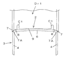
図1は実施の形態にかかるステープラのドライバの刃先を示したものである。このドライバDr1は、例えば、複写機のコピー紙を所定部数仕分けて保持するスタックトレイなどに設けられる電動ステープラのドライバであり、このドライバDr1の刃先2の向かい側には、ステープル3の脚部4、4を内側に折り曲げるクリンチャー(図示省略)が配置される。
【0010】
ドライバDr1の刃先2の下方には、コの字型のステープル3を多数平行に配列し接着したステープル連結体5が供給される(図6A参照)。また、複写機等に設置される電動ステープラにはステープルの装填本数を増大しうるようにシート状に形成したステープル連結体5’(図6B参照)が使用されるものがある。この電動ステープラでは、ステープル連結体5’の送り方向の先端に位置するステープル5’AがドライバDr1の刃先2の下方に供給され、コの字形に成形されて紙束を綴じるようになっている。
【0011】
ドライバDr1の刃先2がステープル連結体5から1本のステープル3を分離してコピー紙に貫通させると、クリンチャーがステープル3の脚部4、4を折り曲げるようになっている。ステープル3の脚部4、4を連結する連結部はクラウン6と称される。
【0012】
なお、このドライバDr1は複写機のスタックトレイに設置される電動ステープラに用いられるものであるが、単体の電動ステープラや手動式のステープラに用いられるものでも良い。ドライバDr1の駆動機構やクリンチャーの駆動機構は、周知の機構で構成されるので、詳細な説明を省略する。
【0013】
ドライバDr1の刃先2は、コの字型のステープル3のクラウン6を押圧して一対の脚部4、4をコピー紙などの紙束に貫通させるために、クラウン6の太さ相当の肉厚を有する平板部とされる。
【0014】
ドライバDr1の刃先2の両端部には、クラウン6の両端部を内側に抱えつつ一対の脚部4、4を押圧する第1の突起部7、7が形成されている。第1の突起部7、7は、脚部4、4の外側を案内する案内面7A、7Aを有している。案内面7A、7Aは、基部側の端部がクラウン6の中央部側に位置し、その先端部がクラウン6の外側に位置するように、傾斜している。第1の突起部7、7の案内面7Aは、ステープル3の脚部4、4をコピー紙に貫通させる際に、脚部4、4の先端部が外側に広がろうとすることを規制する。
【0015】
第1の突起部7、7の近傍には、脚部4、4の座屈耐力を有効に活かすための第2の突起部8、8が形成されている。第2の突起部8、8がステープル3のクラウン6に接触する部位は、ほぼ直角に形成されており、脚部4、4がコピー紙を貫通する際に、第2の突起部8、8がクラウン6に噛み込んだ状態となって、脚部4、4の角部がクラウン6の中央部側に滑ることを防止している。
【0016】
このため、厚い紙束若しくは厚紙の束を綴じるときに脚部4、4が座屈し難くなり、薄い紙束若しくは薄紙の束を綴じるときには、クラウン6全体がアーチ状に変形することが防止される。
【0017】
第2の突起部8,8の間の部分には、ステープル3の脚部4、4がコピー紙に沿って折り曲げられるときに、最終的にクラウン6を押圧する第3の突起部としてのクラウン押圧部9が設けられており、第2の突起部8,8とクラウン押圧部9との間に切り欠き部C1が形成されている。
【0018】
図2のドライバDr2では、第3の突起部としてのクラウン押圧部10が、切り欠き部C1の縁部10Aから少し突出しており、ステープル3のクラウン6の中央部を十分に押圧可能になっている。その他の構成は図1のドライバDr1と同様であるのでその説明を援用する。
【0019】
図3は、第3の実施の形態のドライバDr3を示したものであり、このドライバDr3においては、第2の突起部8、8に近い部分に突起部P1、P1が形成されている。突起部P1,P1は、第2の突起部8、8がステープル3の角部に食い込んだ状態になるときに、クラウン6と突起部P1,P1との間に僅かな隙間が形成されるように、第2の突起部8、8より突出量が小さく設定されている。一対の突起部P1,P1の間の部分は、ステープル3の脚部4、4がコピー紙に沿って折り曲げられるときに、最終的にクラウン6を押圧する第3の突起部としてのクラウン押圧部10とされている。
【0020】
この第1の突起部7、7と、第2の突起部8、8及びクラウン押圧部10が設けられていることによって、薄紙を綴じるときには、第1の突起部7、7と、第2の突起部8、8と、クラウン押圧部10がクラウン6の全体を押圧することが出来ることとなり、クラウン6がアーチ状で弓なりに変形することが一層防止される。
【0021】
図4は第4の実施の形態にかかるステープラのドライバを示している。このドライバDr4の刃先には、第1の突起部12、12の内側に、ステープル3の角部近傍に掛止する第2の突起部13、13が形成されている。第2の突起部13、13は矩形状に形成されており、ステープル3の脚部4、4を紙束に貫通させるときに、ステープル3の角部に第2の突起部13、13の2つの角部が局所的に強く当たるようになっている。第2の突起部13、13の角部がステープル3の角部に局所的に接触・押圧することにより、ステープル3の角部がクラウン6の中央部側に変位しようとすることが防止され、厚い紙束若しくは厚紙の束を綴じるときでもステープル3の脚部4、4が座屈し難い。また、薄い紙束若しくは薄紙の束を綴じるときでもステープル3のクラウン6がアーチ状になることが防止される。
【0022】
図4のドライバDr4には、図3のドライバDr3と同様に、第2の突起部13、13に近い部分に突起部P1、P1が形成され、突起部P1,P1は、第2の突起部13、13より突出量が小さく設定されている。一対の突起部P1,P1の間の部分は第3の突起部としてのクラウン押圧部10とされ、クラウン6を押圧するようになっている。
【0023】
【発明の効果】
本願の請求項1,請求項2のステープラのドライバ構造によれば、厚紙を綴じるときでもステープルの脚部の座屈を生じさせず、薄紙を綴じるときにはステープルの脚部間の連結部をアーチ状に突出させないようにステープルを折り曲げることが可能になる。
【図面の簡単な説明】
【図1】本発明の第1の実施の形態にかかるステープラのドライバの構造を示す説明図。
【図2】本発明の第2の実施の形態にかかるステープラのドライバの構造を示す説明図。
【図3】本発明の第3の実施の形態にかかるステープラのドライバの構造を示す説明図。
【図4】本発明の第4の実施の形態にかかるステープラのドライバの構造を示す説明図。
【図5】従来のドライバの構造を示す説明図。
【図6】図6(A)はコの字形のステープル連結体の斜視図、図6(B)はシート状のステープル連結体の斜視図。
【符号の説明】
1 ドライバ
2 刃先
3 ステープル
4 ステープルの脚部
6 クラウン
7 第1の突起部
8 第2の突起部
9 クラウン押圧部[0001]
BACKGROUND OF THE INVENTION
BACKGROUND OF THE
[0002]
[Prior art]
2. Description of the Related Art Conventionally, as a stapler for binding a bundle of paper such as copy paper, a manual type is known in addition to one installed in a copying machine or the like. The stapler is provided with a thin plate driver for driving a U-shaped staple into a paper bundle. When the blade edge of this driver is flat, there is a problem that when the cardboard is bound, a load is applied to the leg portion of the staple and the leg portion and the crown are buckled and easily deformed.
[0003]
Therefore, as shown in FIG. 5, there are
[0004]
[Problems to be solved by the invention]
However, according to the
[0005]
The present invention pays attention to such a problem, and does not cause buckling of the leg portions of the staples even when binding a thick paper bundle or a thick paper bundle, and when binding a thin paper bundle or a thin paper bundle, It is an object of the present invention to prevent the binding portion from becoming thick or easily broken by preventing the connecting portion between the leg portions from protruding in an arch shape.
[0006]
[Means for Solving the Problems]
In order to solve the above-described problems, a stapler driver structure according to the present invention is a stapler that presses a U-shaped staple having a connecting portion between a pair of leg portions to penetrate the pair of leg portions into a paper bundle. In the driver structure of
The both ends of the flat plate portion that presses the staple are inclined to guide the outside of the leg so that the end on the base side is located on the center of the crown and the tip is located on the outside of the crown. A first projection having a guide surface and holding the both ends of the crown inward while pressing the pair of legs in the vertical direction, and the pair of legs is disposed in the vicinity of the first projection. When the paper bundle is passed through , a second protrusion is formed to be hooked on the vicinity of the pair of legs of the connecting portion, and a notch is formed between the second protrusion and the crown pressing portion. By forming, the portion where the second protrusion comes into contact with the crown of the staple is formed at a substantially right angle .
[0007]
The stapler driver structure according to
[0008]
DETAILED DESCRIPTION OF THE INVENTION
Hereinafter, a driver structure of a stapler according to an embodiment of the present invention will be described with reference to the drawings.
[0009]
FIG. 1 shows a blade edge of a driver of a stapler according to an embodiment. The driver Dr1 is, for example, an electric stapler driver provided on a stack tray that sorts and holds a predetermined number of copies of a copy paper of a copying machine. A clincher (not shown) that
[0010]
Below the
[0011]
When the
[0012]
The driver Dr1 is used for an electric stapler installed on the stack tray of the copying machine, but may be used for a single electric stapler or a manual stapler. Since the driving mechanism of the driver Dr1 and the driving mechanism of the clincher are configured by well-known mechanisms, detailed description thereof is omitted.
[0013]
The
[0014]
At both ends of the
[0015]
In the vicinity of the
[0016]
Therefore, the
[0017]
In the portion between the
[0018]
In the driver Dr2 of FIG. 2, the
[0019]
FIG. 3 shows a driver Dr3 according to the third embodiment. In this driver Dr3, protrusions P1 and P1 are formed in portions close to the
[0020]
By providing the
[0021]
FIG. 4 shows a stapler driver according to the fourth embodiment. On the blade edge of the driver Dr4,
[0022]
The driver Dr4 in FIG. 4 has protrusions P1 and P1 formed in portions close to the
[0023]
【The invention's effect】
According to the stapler driver structure of
[Brief description of the drawings]
FIG. 1 is an explanatory diagram illustrating a structure of a driver of a stapler according to a first embodiment of the invention.
FIG. 2 is an explanatory diagram showing a structure of a stapler driver according to a second embodiment of the present invention;
FIG. 3 is an explanatory diagram showing the structure of a stapler driver according to a third embodiment of the present invention;
FIG. 4 is an explanatory diagram showing the structure of a stapler driver according to a fourth embodiment of the present invention;
FIG. 5 is an explanatory diagram showing a structure of a conventional driver.
6A is a perspective view of a U-shaped staple coupling body, and FIG. 6B is a perspective view of a sheet-like staple coupling body.
[Explanation of symbols]
DESCRIPTION OF
Claims (2)
前記ステープルを押圧する平板部の両端部に、基部側の端部がクラウンの中央部側に位置し、その先端部がクラウンの外側に位置するように、傾斜して脚部の外側を案内する案内面を有し、クラウンの両端部を内側に抱えつつ一対の脚部を垂直方向に押圧する第1の突起部を備えると共に、
この第1の突起部の近傍に、前記一対の脚部を前記紙束に貫通させる際に前記連結部の前記一対の脚部近傍部位に掛け止める第2の突起部をそれぞれ形成し、
前記第2の突起部とクラウン押圧部との間に切り欠き部を形成することで、第2の突起部がステープルのクラウンに接触する部位をほぼ直角に形成したことを特徴とするステープラのドライバ構造。In a stapler driver structure that presses a U-shaped staple having a connecting portion between a pair of legs, and passes the pair of legs through a paper bundle,
The both ends of the flat plate portion that presses the staple are inclined to guide the outside of the leg so that the end on the base side is located on the center of the crown and the tip is located on the outside of the crown. Having a guide surface, and having a first protrusion that presses a pair of legs in the vertical direction while holding both ends of the crown inside ,
In the vicinity of the first protrusion, a second protrusion is formed to be hooked to the vicinity of the pair of legs of the connecting portion when the pair of legs are passed through the paper bundle .
The stapler is characterized in that a notch portion is formed between the second protrusion portion and the crown pressing portion so that a portion where the second protrusion portion contacts the crown of the staple is formed at a substantially right angle . Driver structure.
前記ドライバの第2の突起部同士の間に、前記一対の脚部を前記紙束に貫通させる際に前記ステープルの連結部の中間部を押す第3の突起部を設けたことを特徴とするステープラのドライバ構造。In the driver structure of the stapler according to claim 1,
A third protrusion is provided between the second protrusions of the driver to push an intermediate portion of the staple connecting portion when the pair of legs are passed through the paper bundle. Stapler driver structure.
Priority Applications (8)
| Application Number | Priority Date | Filing Date | Title |
|---|---|---|---|
| JP2002210923A JP4023246B2 (en) | 2002-07-19 | 2002-07-19 | Stapler driver structure |
| EP03765322A EP1541289B1 (en) | 2002-07-19 | 2003-07-18 | Driver structure of stapler |
| DE60332249T DE60332249D1 (en) | 2002-07-19 | 2003-07-18 | DRIVER CONSTRUCTION FOR A STACKER |
| KR1020057000835A KR100613953B1 (en) | 2002-07-19 | 2003-07-18 | A driver structure of a stapler |
| US10/524,710 US7510106B2 (en) | 2002-07-19 | 2003-07-18 | Driver structure of stapler |
| AU2003248080A AU2003248080A1 (en) | 2002-07-19 | 2003-07-18 | Driver structure of stapler |
| CNB038161443A CN100396443C (en) | 2002-07-19 | 2003-07-18 | Driver structure of stapler |
| PCT/JP2003/009137 WO2004009296A1 (en) | 2002-07-19 | 2003-07-18 | Driver structure of stapler |
Applications Claiming Priority (1)
| Application Number | Priority Date | Filing Date | Title |
|---|---|---|---|
| JP2002210923A JP4023246B2 (en) | 2002-07-19 | 2002-07-19 | Stapler driver structure |
Publications (2)
| Publication Number | Publication Date |
|---|---|
| JP2004050350A JP2004050350A (en) | 2004-02-19 |
| JP4023246B2 true JP4023246B2 (en) | 2007-12-19 |
Family
ID=30767754
Family Applications (1)
| Application Number | Title | Priority Date | Filing Date |
|---|---|---|---|
| JP2002210923A Expired - Lifetime JP4023246B2 (en) | 2002-07-19 | 2002-07-19 | Stapler driver structure |
Country Status (8)
| Country | Link |
|---|---|
| US (1) | US7510106B2 (en) |
| EP (1) | EP1541289B1 (en) |
| JP (1) | JP4023246B2 (en) |
| KR (1) | KR100613953B1 (en) |
| CN (1) | CN100396443C (en) |
| AU (1) | AU2003248080A1 (en) |
| DE (1) | DE60332249D1 (en) |
| WO (1) | WO2004009296A1 (en) |
Families Citing this family (15)
| Publication number | Priority date | Publication date | Assignee | Title |
|---|---|---|---|---|
| US8714429B2 (en) * | 2003-04-29 | 2014-05-06 | Covidien Lp | Dissecting tip for surgical stapler |
| JP4941001B2 (en) * | 2007-02-28 | 2012-05-30 | マックス株式会社 | Staple driving driver |
| JP5071003B2 (en) * | 2007-09-05 | 2012-11-14 | マックス株式会社 | Stapler |
| TWI461266B (en) * | 2007-09-05 | 2014-11-21 | Max Co Ltd | Stapler |
| JP5076754B2 (en) * | 2007-09-05 | 2012-11-21 | マックス株式会社 | Stapler |
| EP2087966A1 (en) * | 2008-02-05 | 2009-08-12 | Hua Ding Zhang | Tack device for multi-purpose fastening tool |
| DE102008012511A1 (en) * | 2008-03-04 | 2009-09-10 | Esselte Leitz Gmbh & Co. Kg | Stapler |
| US8870049B2 (en) * | 2008-03-14 | 2014-10-28 | Transenterix, Inc. | Hernia stapler |
| EP2257227A4 (en) * | 2008-03-14 | 2014-03-26 | Safestitch Medical Inc | Hernia stapler with integrated mesh manipulator |
| US8985427B1 (en) * | 2009-05-05 | 2015-03-24 | Cardica, Inc. | Feeder belt with internally manufactured staples for true multi-fire surgical stapler |
| JP5454631B2 (en) * | 2012-07-09 | 2014-03-26 | マックス株式会社 | Stapler |
| JP6091798B2 (en) * | 2012-08-08 | 2017-03-08 | マニー株式会社 | Medical stapler anvil |
| JP6870281B2 (en) * | 2016-10-31 | 2021-05-12 | マックス株式会社 | Stapler |
| US11524396B2 (en) | 2019-02-28 | 2022-12-13 | Black & Decker, Inc. | Fastener tool |
| EP4188236A1 (en) * | 2020-07-29 | 2023-06-07 | Magstape LLC | Biometallic alloy surgical staples and methods |
Family Cites Families (19)
| Publication number | Priority date | Publication date | Assignee | Title |
|---|---|---|---|---|
| US2923938A (en) * | 1960-02-09 | Stapling machine | ||
| FR846928A (en) | 1937-12-08 | 1939-09-28 | Apparatus for driving in broaching staples, and having a number of different and interchangeable driving punches | |
| US2351045A (en) * | 1942-06-25 | 1944-06-13 | Harold S Heller | Staple |
| FR969859A (en) | 1948-07-22 | 1950-12-27 | Stapler enhancements | |
| US3524575A (en) * | 1967-03-30 | 1970-08-18 | Swingline Inc | Electric stapling machinne |
| BE790493A (en) | 1971-10-26 | 1973-04-24 | Sandoz Sa | NEW HETEROCYCLIC COMPOUNDS FOR USE AS ORGANIC STABILIZERS AND THEIR PREPARATION |
| JPS4861476U (en) * | 1971-11-12 | 1973-08-04 | ||
| US4043504A (en) * | 1976-03-09 | 1977-08-23 | Senco Products, Inc. | Staple cartridge and feed means for use with a surgical stapling instrument |
| DE3641477A1 (en) | 1986-12-04 | 1988-06-16 | Bosch Gmbh Robert | Tacker |
| JPS63162168A (en) | 1986-12-26 | 1988-07-05 | 旭木材工業株式会社 | Tacker |
| US4747531A (en) * | 1987-03-23 | 1988-05-31 | Ethicon, Inc. | Anvil and driver assembly for a surgical skin stapling instrument |
| US4919320A (en) * | 1988-03-07 | 1990-04-24 | Technalytics, Inc. | Surgical stapler |
| JPH0985644A (en) | 1995-09-26 | 1997-03-31 | Yoshio Ichiki | Stapler |
| JP3355900B2 (en) * | 1995-12-21 | 2002-12-09 | マックス株式会社 | Staple driver |
| US5846019A (en) * | 1996-08-06 | 1998-12-08 | Kuhns; Philip A. | Fasteners |
| JPH10146803A (en) | 1996-11-18 | 1998-06-02 | Natl House Ind Co Ltd | Staple striking blade |
| US6474633B1 (en) * | 1999-10-04 | 2002-11-05 | Canon Kabushiki Kaisha | Stapler with interchangeable cartridges |
| SE522763C2 (en) | 1999-11-19 | 2004-03-02 | Isaberg Rapid Ab | Stapler driver intended for mounting in a stapler |
| US7011242B2 (en) * | 2001-12-07 | 2006-03-14 | Acme Staple Company, Inc. | Coated staple and fastening tool for the same |
-
2002
- 2002-07-19 JP JP2002210923A patent/JP4023246B2/en not_active Expired - Lifetime
-
2003
- 2003-07-18 KR KR1020057000835A patent/KR100613953B1/en not_active IP Right Cessation
- 2003-07-18 AU AU2003248080A patent/AU2003248080A1/en not_active Abandoned
- 2003-07-18 EP EP03765322A patent/EP1541289B1/en not_active Expired - Lifetime
- 2003-07-18 WO PCT/JP2003/009137 patent/WO2004009296A1/en active Application Filing
- 2003-07-18 US US10/524,710 patent/US7510106B2/en not_active Expired - Lifetime
- 2003-07-18 DE DE60332249T patent/DE60332249D1/en not_active Expired - Lifetime
- 2003-07-18 CN CNB038161443A patent/CN100396443C/en not_active Expired - Lifetime
Also Published As
| Publication number | Publication date |
|---|---|
| EP1541289B1 (en) | 2010-04-21 |
| WO2004009296A1 (en) | 2004-01-29 |
| EP1541289A4 (en) | 2008-05-14 |
| CN1665644A (en) | 2005-09-07 |
| JP2004050350A (en) | 2004-02-19 |
| KR20050023431A (en) | 2005-03-09 |
| DE60332249D1 (en) | 2010-06-02 |
| KR100613953B1 (en) | 2006-08-22 |
| US7510106B2 (en) | 2009-03-31 |
| CN100396443C (en) | 2008-06-25 |
| AU2003248080A1 (en) | 2004-02-09 |
| US20060006208A1 (en) | 2006-01-12 |
| EP1541289A1 (en) | 2005-06-15 |
Similar Documents
| Publication | Publication Date | Title |
|---|---|---|
| JP4023246B2 (en) | Stapler driver structure | |
| JP4419335B2 (en) | Staple cartridge system | |
| WO2017209162A1 (en) | Teeth part, binder, paper-processing apparatus, and image formation system | |
| TW555630B (en) | Staple cartridge of electric stapler | |
| TWI343857B (en) | ||
| JPH07285681A (en) | Paper sheet guide member of paper feeding device | |
| WO2010074111A1 (en) | Penetration load reducing staple | |
| US7234622B2 (en) | Stapler, cartridge for stapler, and system having the stapler and cartridge in combination | |
| JP7003824B2 (en) | cartridge | |
| TWI224992B (en) | Staple pack | |
| JP2689840B2 (en) | Staple cartridge and staple sheet pack | |
| JPH0985644A (en) | Stapler | |
| WO2005115698A1 (en) | Clincher device for stapler | |
| JP2021079572A (en) | Electric stapler | |
| JP3014464U (en) | Paper feed cassettes for fax machines, etc. | |
| JP2017013996A (en) | Sheet processing device and image formation apparatus having the same | |
| JP4045048B2 (en) | Paper feed tray and image forming apparatus | |
| JP2797629B2 (en) | Sheet storage cassette | |
| JP3489357B2 (en) | Clamping mechanism of clamping device | |
| JPH1134566A (en) | Clip | |
| JP4114061B2 (en) | Articulated staples | |
| JP3131542U (en) | Stapler with slip prevention | |
| JP2004142074A (en) | Stapler | |
| JP6568416B2 (en) | Sheet processing apparatus and image forming apparatus having the same | |
| KR200386018Y1 (en) | Assistant equipment for sheetbinding |
Legal Events
| Date | Code | Title | Description |
|---|---|---|---|
| A621 | Written request for application examination |
Free format text: JAPANESE INTERMEDIATE CODE: A621 Effective date: 20050512 |
|
| A131 | Notification of reasons for refusal |
Free format text: JAPANESE INTERMEDIATE CODE: A131 Effective date: 20070703 |
|
| A521 | Request for written amendment filed |
Free format text: JAPANESE INTERMEDIATE CODE: A523 Effective date: 20070724 |
|
| TRDD | Decision of grant or rejection written | ||
| A01 | Written decision to grant a patent or to grant a registration (utility model) |
Free format text: JAPANESE INTERMEDIATE CODE: A01 Effective date: 20070911 |
|
| A61 | First payment of annual fees (during grant procedure) |
Free format text: JAPANESE INTERMEDIATE CODE: A61 Effective date: 20070924 |
|
| R150 | Certificate of patent or registration of utility model |
Ref document number: 4023246 Country of ref document: JP Free format text: JAPANESE INTERMEDIATE CODE: R150 Free format text: JAPANESE INTERMEDIATE CODE: R150 |
|
| FPAY | Renewal fee payment (event date is renewal date of database) |
Free format text: PAYMENT UNTIL: 20101012 Year of fee payment: 3 |
|
| FPAY | Renewal fee payment (event date is renewal date of database) |
Free format text: PAYMENT UNTIL: 20101012 Year of fee payment: 3 |
|
| FPAY | Renewal fee payment (event date is renewal date of database) |
Free format text: PAYMENT UNTIL: 20111012 Year of fee payment: 4 |
|
| FPAY | Renewal fee payment (event date is renewal date of database) |
Free format text: PAYMENT UNTIL: 20121012 Year of fee payment: 5 |
|
| FPAY | Renewal fee payment (event date is renewal date of database) |
Free format text: PAYMENT UNTIL: 20131012 Year of fee payment: 6 |
|
| EXPY | Cancellation because of completion of term |