JP4019182B2 - Visual equipment - Google Patents
Visual equipment Download PDFInfo
- Publication number
- JP4019182B2 JP4019182B2 JP21389495A JP21389495A JP4019182B2 JP 4019182 B2 JP4019182 B2 JP 4019182B2 JP 21389495 A JP21389495 A JP 21389495A JP 21389495 A JP21389495 A JP 21389495A JP 4019182 B2 JP4019182 B2 JP 4019182B2
- Authority
- JP
- Japan
- Prior art keywords
- camera
- illumination light
- light source
- vehicle
- illumination
- Prior art date
- Legal status (The legal status is an assumption and is not a legal conclusion. Google has not performed a legal analysis and makes no representation as to the accuracy of the status listed.)
- Expired - Fee Related
Links
Images


Description
【0001】
【産業上の利用分野】
本発明は、カメラによって撮像した画像によって撮像領域を認識する視覚装置に関する。
【0002】
【従来の技術】
従来、ビデオカメラを車両に搭載して、前方領域をビデオカメラにより撮像して、その撮像画像から障害物を認識するようにしている(特開平6−215300号公報参照)。
【0003】
しかし、ビデオカメラによるのでは、霧中などでは車両のヘッドライトを点灯しても前方領域の撮像をなすことができない。
【0004】
すなわち、例えば、図8に示すように、照明光LLの開き角度6が比較的広いヘッドライト4により前方の領域を照明し、その照明領域からの反射光RLをビデオカメラ2によって受光して照明領域の撮像をなす場合、照明領域に霧、煙、粉塵等のエアロゾルZが存在すると、照明光LLがそのエアロゾルZによって散乱されてしまい、その散乱光のなかのビデオカメラ2の受光部に向かう光Nがビデオカメラ2にノイズとなって受光される。また、エアロゾルZを通過した照明光LLの一部が照明領域にある物体3を照射するが、その反射光RLもさらにエアロゾルZによって散乱されて減衰し、反射光RLのうちのわずかな光しかビデオカメラ2によって受光されなくなる。
【0005】
したがって、照明領域におけるエアロゾルZの量が多くなるにしたがって、ノイズが増えて、照明領域からの反射光RLの受光量が減り、照明光LLの光強度を上げてもビデオカメラ2によって照明領域の撮像をなすことが困難になってしまう。
【0006】
また、従来、赤外線カメラを車両に搭載して、前方領域を赤外線カメラにより撮像して、その撮像画像から障害物を認識するようにしている(特開昭54−92117号公報参照)。
【0007】
しかし、赤外線カメラによるのでは、夜間や霧中などでも人間や自動車などの赤外線の放射量の多い物体を比較的良好に認識することはできても、前方道路を認識しようとする場合、赤外線の放射量の少ない路面や道路構造物を明瞭に認識することができず、特に道路上の白線などの認識をなすことが困難である。
【0008】
【発明が解決しようとする課題】
解決しようとする問題点は、従来のビデオカメラを用いた視覚装置では、霧、煙、粉塵等のエアロゾル中では前方領域を撮像することができない。また、赤外線カメラを用いた視覚装置では、赤外線の放射量の少ない物体を認識することができないということである。
【0009】
【課題を解決するための手段】
本発明は、車両に搭載したカメラによって車両の前方領域を撮像するに際して、霧、煙、粉塵等のエアロゾル中にあっても良好な撮像画像を得ることができるようにするべく、照明用光源によって照明される領域を撮像する路面撮像用の第1のカメラと、その第1のカメラとは感度が異なる波長帯域で同一方を撮像する障害物撮像用の第2のカメラとをそなえ、第1および第2の各カメラによってそれぞれ撮像された画像の合成画像を得る手段をとるようにしている。
【0010】
その際、特に本発明では、第1のカメラに可視光または近赤外線の周波数帯域に感度を示すものを用いたうえで、照明用光源から発せられろ照明光の開き角および第1のカメラの1画素の視野角が、照明光の光軸とその照明光が照射される物体からの第1のカメラへの反射光の光軸とのなす角よりも小さくなるように、照明用光源と第1のカメラとを設置する際の相対的な関係を工夫して、霧、煙、粉塵等のエアロゾル中にあっても、第1のカメラによりエアロゾルによる散乱ノイズに対してSN比の高い反射光を得て照明領域の撮像を行わせることができるようにしている。
【0011】
そして、第2のカメラに10μm前後の赤外線の周波数帯域に感度を示すものを用いて、霧、煙、粉塵等のエアロゾル中にあっても、赤外線を放射する人間や自動車などの障害物の認識を比較的広い範囲にわたって明瞭に行うことができるようにしている。
【0012】
【実施例】
図5は、照明用光源1とビデオカメラ2との間の設置間隔Dを可変にしながら、照明光LLの開き角度θ1を種々に変えたときの反射光RLのSN比を測定するシュミレーションモデルを示しており、L=50m先で可視光による照明光LLの透過率が約5%に低下する霧中で、50m先に置いた反射率1の物体3からの反射光RLをビデオカメラ2によって受光するようにしている。
【0013】
図6は、そのときのシュミレーション結果の特性を示している。その特性図は、横軸に照明用光源1とビデオカメラ2との間の設置間隔Dをとり、縦軸にSN比をとっている。また、照明光LLの開き角度θ1として、0.5mrad(ミリフラジアン)、lmrad、5mrad、17mrad、85mradの各パラメータをとっている。
【0014】
このシュミレーション結果をみれば、照明用光源1から発せられる照明光LLの開き角度θ1を小さくするほどSN比が良くなることがわかる。このことは、ビデオカメラ2における1画素の受光の開き角度(視野角)θ2を小さくしても同様である。また、照明用光源1とビデオカメラ2との間の設置間隔Dが大きいほどSN比が良くなることがわがる。
【0015】
このことは、照明光LLの開き角度θ1またはビデオカメラ2における視野角θ2を小さくし、また、照明用光源1と光センサ2との間の設置間隔Dを大きくすると、照明光LLの照明領域Aと反射光RLの反射領域Bとの重合領域Cの大きさが小さくなり、霧により照明光LLが散乱したときのビデオカメラ2の受光部に向かうノイズ光の量が抑制されるためと考えられる。
【0016】
照明用光源1から発せられる照明光LLとしては、霧、煙、粉塵等のエアロゾル中での透過性の良い赤外線を用いることが考えられるが、以下の理由からして、可視光か近赤外線を用いるのが適当である。
【0017】
すなわち、照明用光源1およびビデオカメラ2を車両に搭載して前方の道路を撮像するような場合など、物体に照明光LLを斜めに照射したときにも物体からの反射光を充分に得ることができるようにするために、物体の表面の凹凸よりも小さな波長をもった照明光を用いるのがよく、赤外線よりも波長の短い可視光か近赤外線のほうが適している。
【0018】
また、図7は、平均粒径を1〜10μmの範囲で変えた人工の霧中での電磁波の透過率を同一条件下で測定したときの特性図であり、その測定が果からして、10μm前後(5〜20μmの範囲)の赤外線の透過率が高いことがわかる。
【0019】
そして、物体は自ら電磁波を放射しており、常温では10μm付近の赤外線が最も多く放射されていることがわかっている。
【0020】
したがって、特に10μm前後の周波数帯域に感度を示す赤外線カメラを用いれば、霧、煙、粉塵等のエアロゾル中にあっても物体を撮像することができ、特に、道路環境を想定する場合、人間や自動車などの周囲に比べて温度が高くて赤外線の放射量の多い物体を認識することができるようになる。
【0021】
図1は、以上の検討結果を考慮したうえで構成された本発明による視覚装置の一実施例を示すもので、ここでは、その視覚装置を車両に搭載して、霧、煙、粉塵等のエアロゾル中にあっても、主として、ビデオカメラ2によって照明用光源1による車両前方における道路の照明領域の撮像を可能とし、また、赤外線カメラ5によって車両の前方領域に存在する人間や自動車などの障害物の撮像を広範囲にわたって行わせて、その各撮像画像を画像合成器(図示せず)によって合成するようにしている。
【0022】
照明用光源1とビデオカメラ2は、車両7の前部の上下方向に、照明用光源1における照明光LLの開き角度θおよびビデオカメラ2の視野角θが、前方の路面8を照射する照明光LLの光軸と路面8からの反射光RLの光軸とのなす角αよりも小さくなるような関係(θ,θ<α)をもって配設されている。
【0023】
しかして、θ1,θ2<αの関係を満足するように照明用光源1とビデオカメラ2とを車両7の前部に配設することにより、照明領域に霧、煙、粉塵等のエアロゾルが存在しても、そのエアロゾルにより照明光LLが散乱したときのビデオカメラ2の受光部に向かうノイズ光量が最小限に抑制されたSN比の高い反射光RLをビデオカメラ2によって受光することができるようになり、車両前方の路面8の撮像を有効に行わせることができるようになる。
【0024】
その際、例えば、霧中走行時の前方視界を必要最小限に確保するべく、車両7の前方数mほど先の路面8上を照明できるように照明用光源1およびビデオカメラ2をセットする。そして、その路面8を充分な幅をもって撮像することができるようにするべく、照明用光源1にそれから発せられる照明光LLが左右方向に広がるようなアパーチャーをもたせるとともに、ビデオカメラ2の受光部も同様に左右方向の広がりをもたせるようにする。
【0025】
図2は、このようにして照明用光源1およびビデオカメラ2を車両7の前部に取り付けたときのビデオカメラ2による路面8の撮像画像の一例を示しており、ここでは路面8上に引かれた道路端および中央線の白線9が明瞭に撮像されている。
【0026】
なお、その際、車両7のヘッドライト4を点灯することにより見える手前の路面8をもビデオカメラ2によって同時に撮像することができるようになる。
【0027】
照明用光源1にもヘッドライト4にも照明されない部分は、両者のデータから予測する。また、照明用光源1を1ラインではなく、複数ライン走査することでデータを増やすことができるようになる。
【0028】
また、赤外線カメラ5は、車両の前方領域を広範囲にわたって撮像することができるように、車両7の前部に設置されている。
【0029】
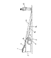
図3は、赤外線カメラ5による撮像画像の一例を示しており、ここでは車両の前方の照明用光源1による照明領域外にいる人間10が明瞭に撮像されている。
【0030】
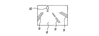
しかして、霧中などの車両7の走行時にあっても、このようなビデオカメラ2による撮像画像と赤外線カメラ5による撮像画像とを画像合成器によって合成することにより、図4に示すように、照明用光源1によって照明されている車両前方の路面8とその照明領域外にいる人間10とが一体となった実際に即した画像が得られるようになる。
【0031】
そして、その合成画像を、例えばヘッドアップディスプレイを用いて運転席側のフロントガラス方に写し出すようにすれば、見通しのきかない濃い霧中での車両走行時にあっても、運転者は前方の道路状態を認識し、また、前方に人間や自動車などの障害物があることを認識することができるようになる。
【0032】
また、その合成画像のデータを自動走行装置に与えて、障害物を避けながら道路上を自動走行するような制御を行わせるようにすることも可能である。
【0033】
さらに、本発明は車載用に限らず、自動走行ロボットの視覚装置として、また、一般の監視用の視覚装置などとして広く用いられることはいうまでもない。
【0034】
【効果】
以上、本発明による視覚装置によれば、車両の上部に設置されて車両の前方領域を照明する照明用光源と、車両における前記照明用光源の下方に設置され、その光源によって照明される領域を撮像する可視光または近赤外線の周波数帯域に感度を示す路面撮像用の第1のカメラと、車両に設置されて第1のカメラと同一方を撮像する10μm前後の赤外線の周波数帯域に感度を示す赤外線を放射する人間などの障害物撮像用の第2のカメラと、第1および第2の各カメラによってそれぞれ撮像された画像の合成画像を得る手段とをそなえ、照明用光源から発せられる照明光の開き角および第1のカメラの視野角が、照明光の光軸と照明領域から第1のカメラへの反射光の光軸とのなす角よりも小さくなるような関係をもって、照明用光源と第1のカメラとを配設することにより、視界のきかないエアロゾル中にあっても車両前方の路面およびその前方領域に存在する人間などの障害物に係る実際に即した明瞭な撮像画像を得ることができ、運転視界を確保することができるようになる。
【図面の簡単な説明】
【図1】本発明による視覚装置の一実施例を示す概略構成図である。
【図2】同実施例において照明用光源による照明領域をビデオカメラによって撮像した画像の一例を示す図である。
【図3】同実施例において赤外線カメラによって撮像した画像の一例を示す図である。
【図4】ビデオカメラによる撮像画像と赤外線カメラによる撮像画像とを合成した画像の一例を示す図である。
【図5】照明用光源による照明領域をビデオカメラにより撮像する際の反射光のSN比を測定するシュミレーションモデルの概略構成図である。
【図6】照明光の開き角をパラメータにとり、横軸に照明用光源とビデオカメラとの間隔をとり、縦軸にSN比をとったシュミレーション結果の特性図である。
【図7】粒径を1〜10μmの範囲で変えた人工の霧中での電磁波の透過率を同一条件下で測定したときの特性図である。
【図8】従来の車両のヘッドライトによる照明領域をビデオカメラによって撮像するときの状態を示す概略構成図である。
【符号の説明】
1 照明用光源
2 ビデオカメラ
4 ヘッドライト
5 赤外線カメラ
7 車両
8 路面[0001]
[Industrial application fields]
The present invention relates to a visual device that recognizes an imaging region from an image captured by a camera.
[0002]
[Prior art]
Conventionally, a video camera is mounted on a vehicle, a front area is imaged by the video camera, and an obstacle is recognized from the captured image (see JP-A-6-215300).
[0003]
However, with a video camera, it is not possible to image the front area even when the vehicle headlight is turned on, such as in fog.
[0004]
That is, for example, as shown in FIG. 8, a front area is illuminated by a headlight 4 having a relatively wide opening angle 6 of illumination light LL, and reflected light RL from the illumination area is received by a
[0005]
Therefore, as the amount of the aerosol Z in the illumination area increases, noise increases, the amount of reflected light RL received from the illumination area decreases, and even if the light intensity of the illumination light LL is increased, the
[0006]
Conventionally, an infrared camera is mounted on a vehicle, the front area is imaged by the infrared camera, and an obstacle is recognized from the captured image (see Japanese Patent Laid-Open No. 54-92117).
[0007]
However, with infrared cameras, it is possible to recognize objects with a large amount of infrared radiation, such as humans and automobiles, even at night or in fog. A road surface or road structure with a small amount cannot be clearly recognized, and it is particularly difficult to recognize a white line on the road.
[0008]
[Problems to be solved by the invention]
The problem to be solved is that a visual device using a conventional video camera cannot image the front area in an aerosol such as fog, smoke, and dust. In addition, a visual device using an infrared camera cannot recognize an object with a small amount of infrared radiation.
[0009]
[Means for Solving the Problems]
The present invention uses an illumination light source so that a good captured image can be obtained even in an aerosol such as fog, smoke, dust, etc., when a front area of the vehicle is imaged by a camera mounted on the vehicle . A first camera for imaging a road surface that images an illuminated area, and a second camera for imaging an obstacle that images the same in a wavelength band having a sensitivity different from that of the first camera. respectively so as to take the resulting Ru means a composite image of an image captured by and the second of each camera.
[0010]
At that time, in the present invention, in particular, the first camera having sensitivity in the visible light or near infrared frequency band is used, and then the opening angle of the illumination light emitted from the illumination light source and the first camera The illumination light source and the first light source are arranged so that the viewing angle of one pixel is smaller than the angle between the optical axis of the illumination light and the optical axis of the reflected light from the object irradiated with the illumination light to the first camera. Reflective light with high S / N ratio against scattering noise caused by aerosol by the first camera even if it is in aerosol such as fog, smoke, dust, etc. So that the illumination area can be imaged.
[0011]
Using a second camera that shows sensitivity in the infrared frequency band around 10 μm , it recognizes obstacles such as humans and automobiles that emit infrared rays even in aerosols such as fog, smoke, and dust. Can be performed clearly over a relatively wide range.
[0012]
【Example】
FIG. 5 shows a simulation model for measuring the S / N ratio of the reflected light RL when the opening angle θ 1 of the illumination light LL is variously changed while the installation distance D between the
[0013]
FIG. 6 shows the characteristics of the simulation result at that time. In the characteristic diagram, the horizontal axis represents the installation interval D between the
[0014]
From this simulation result, it can be seen that the SN ratio is improved as the opening angle θ 1 of the illumination light LL emitted from the illumination light source 1 is decreased. This is the same even if the opening angle (viewing angle) θ 2 of light reception of one pixel in the video camera 2 is reduced. It can also be seen that the S / N ratio is improved as the installation distance D between the
[0015]
This reduces the viewing angle theta 2 at an angle theta 1 or the
[0016]
As the illumination light LL emitted from the
[0017]
That is, when the
[0018]
FIG. 7 is a characteristic diagram when the transmittance of electromagnetic waves in an artificial mist with the average particle diameter changed in the range of 1 to 10 μm is measured under the same conditions. It turns out that the transmittance | permeability of the infrared rays before and behind (the range of 5-20 micrometers) is high.
[0019]
The object itself radiates electromagnetic waves, and it is known that infrared rays around 10 μm are radiated most at room temperature.
[0020]
Therefore, if an infrared camera showing sensitivity in a frequency band around 10 μm is used, an object can be imaged even in an aerosol such as fog, smoke, dust, etc. This makes it possible to recognize an object that has a higher temperature and a greater amount of infrared radiation than an automobile or the like.
[0021]
FIG. 1 shows an embodiment of a visual device according to the present invention configured in consideration of the above examination results. Here, the visual device is mounted on a vehicle and fog, smoke, dust, etc. Even in the aerosol, the
[0022]
The
[0023]
Thus, by arranging the
[0024]
At this time, for example, the
[0025]
FIG. 2 shows an example of an image captured on the
[0026]
At this time, the
[0027]
A portion that is neither illuminated by the
[0028]
Moreover, the
[0029]
FIG. 3 shows an example of an image captured by the
[0030]
Thus, even when the
[0031]
Then, if the composite image is projected on the windshield side of the driver's seat using, for example, a head-up display, the driver will be able to And it is possible to recognize that there are obstacles such as humans and automobiles ahead.
[0032]
It is also possible to provide the automatic traveling device with the data of the composite image so as to perform control so as to automatically travel on the road while avoiding obstacles.
[0033]
Furthermore, it goes without saying that the present invention is not limited to being mounted on a vehicle but is widely used as a visual device for an automatic traveling robot, a general visual device for monitoring, and the like.
[0034]
【effect】
As described above, according to the visual device of the present invention, the illumination light source that is installed in the upper part of the vehicle and illuminates the front area of the vehicle, and the area that is installed below the illumination light source in the vehicle and illuminated by the light source A first camera for road surface imaging showing sensitivity in a visible light or near infrared frequency band to be imaged, and a sensitivity in an infrared frequency band around 10 μm which is installed in a vehicle and images the same as the first camera. Illumination light emitted from an illumination light source, comprising a second camera for imaging an obstacle such as a human being that emits infrared rays, and means for obtaining a composite image of the images respectively captured by the first and second cameras And a light source for illumination having a relationship such that the opening angle of the light source and the viewing angle of the first camera are smaller than the angle formed by the optical axis of the illumination light and the optical axis of the reflected light from the illumination region to the first camera First By disposing the camera, to obtain a clear captured image actually conformity according to obstacles such as a human even in the aerosol not hear the visibility present in the road surface and its front region in front of the vehicle It can, be so that it is possible to ensure the driving view field.
[Brief description of the drawings]
FIG. 1 is a schematic configuration diagram showing an embodiment of a visual device according to the present invention.
FIG. 2 is a diagram illustrating an example of an image obtained by capturing an illumination area of an illumination light source with a video camera in the embodiment.
FIG. 3 is a diagram showing an example of an image captured by an infrared camera in the same embodiment.
FIG. 4 is a diagram illustrating an example of an image obtained by combining an image captured by a video camera and an image captured by an infrared camera.
FIG. 5 is a schematic configuration diagram of a simulation model for measuring an S / N ratio of reflected light when an illumination area by an illumination light source is imaged by a video camera.
FIG. 6 is a characteristic diagram of a simulation result in which the opening angle of illumination light is a parameter, the horizontal axis is the distance between the illumination light source and the video camera, and the vertical axis is the SN ratio.
FIG. 7 is a characteristic diagram when the transmittance of electromagnetic waves in an artificial mist having a particle diameter changed in the range of 1 to 10 μm is measured under the same conditions.
FIG. 8 is a schematic configuration diagram showing a state when a video camera captures an image of an illumination area of a conventional vehicle headlight.
[Explanation of symbols]
1 Light source for
Claims (1)
Priority Applications (2)
| Application Number | Priority Date | Filing Date | Title |
|---|---|---|---|
| JP21389495A JP4019182B2 (en) | 1995-07-19 | 1995-07-19 | Visual equipment |
| US08/675,163 US6067110A (en) | 1995-07-10 | 1996-07-03 | Object recognizing device |
Applications Claiming Priority (1)
| Application Number | Priority Date | Filing Date | Title |
|---|---|---|---|
| JP21389495A JP4019182B2 (en) | 1995-07-19 | 1995-07-19 | Visual equipment |
Publications (2)
| Publication Number | Publication Date |
|---|---|
| JPH0937147A JPH0937147A (en) | 1997-02-07 |
| JP4019182B2 true JP4019182B2 (en) | 2007-12-12 |
Family
ID=16646781
Family Applications (1)
| Application Number | Title | Priority Date | Filing Date |
|---|---|---|---|
| JP21389495A Expired - Fee Related JP4019182B2 (en) | 1995-07-10 | 1995-07-19 | Visual equipment |
Country Status (1)
| Country | Link |
|---|---|
| JP (1) | JP4019182B2 (en) |
Cited By (1)
| Publication number | Priority date | Publication date | Assignee | Title |
|---|---|---|---|---|
| US20160138965A1 (en) * | 2013-06-04 | 2016-05-19 | Petra Sonja Biedermann | Method and device for detecting infrasound |
Families Citing this family (11)
| Publication number | Priority date | Publication date | Assignee | Title |
|---|---|---|---|---|
| JP4103179B2 (en) * | 1998-06-30 | 2008-06-18 | マツダ株式会社 | Environment recognition device |
| JP2000127850A (en) * | 1998-10-22 | 2000-05-09 | Matsushita Electric Ind Co Ltd | Vehicle outside information detecting device |
| JP3972722B2 (en) * | 2002-04-24 | 2007-09-05 | 株式会社エクォス・リサーチ | In-vehicle image processing device |
| JP3879739B2 (en) * | 2004-02-09 | 2007-02-14 | 日産自動車株式会社 | Pedestrian notification device, pedestrian notification method, and pedestrian notification program |
| US7608825B2 (en) | 2006-12-14 | 2009-10-27 | Sumitomo Electric Industries, Ltd. | Image pickup device, vision enhancement apparatus, night-vision apparatus, navigation support apparatus, and monitoring apparatus |
| JP2009302828A (en) * | 2008-06-12 | 2009-12-24 | Nippon Telegr & Teleph Corp <Ntt> | Monitoring method and device |
| JP5233535B2 (en) | 2008-09-11 | 2013-07-10 | 住友電気工業株式会社 | Imaging device, visual field support device, night vision device, navigation support device, and monitoring device |
| JP2012080524A (en) * | 2010-09-09 | 2012-04-19 | Hitachi Kokusai Electric Inc | Monitoring system |
| JP5633503B2 (en) * | 2011-11-29 | 2014-12-03 | 株式会社リコー | Image processing system, vehicle equipped with image processing system, image processing method and program |
| CN107250841B (en) * | 2015-02-19 | 2021-02-12 | 通快光电器件有限公司 | Infrared laser illumination equipment |
| JP2022117174A (en) * | 2021-01-29 | 2022-08-10 | 株式会社小松製作所 | Display system and display method |
-
1995
- 1995-07-19 JP JP21389495A patent/JP4019182B2/en not_active Expired - Fee Related
Cited By (2)
| Publication number | Priority date | Publication date | Assignee | Title |
|---|---|---|---|---|
| US20160138965A1 (en) * | 2013-06-04 | 2016-05-19 | Petra Sonja Biedermann | Method and device for detecting infrasound |
| US10180348B2 (en) * | 2013-06-04 | 2019-01-15 | Petra Sonja Biedermann | Method and device for detecting infrasound |
Also Published As
| Publication number | Publication date |
|---|---|
| JPH0937147A (en) | 1997-02-07 |
Similar Documents
| Publication | Publication Date | Title |
|---|---|---|
| US6067110A (en) | Object recognizing device | |
| US9286521B2 (en) | Camera system for large vehicles | |
| US7015944B2 (en) | Device for improving visibility in vehicles | |
| JP4019182B2 (en) | Visual equipment | |
| JP2005195601A (en) | System and method of detecting driving conditions for car | |
| JP3822154B2 (en) | Vehicle detection device | |
| WO2001028250A1 (en) | Monitor camera, method of adjusting camera, and vehicle monitor system | |
| JP2006188224A (en) | Night vision system for vehicle, light source operation system and its control method | |
| WO2006118076A1 (en) | System for monitoring periphery of vehicle | |
| JP4566121B2 (en) | Vehicle lighting device | |
| JP2003002138A (en) | Method and device for on-vehicle rear monitoring | |
| JP5045974B2 (en) | Vehicle driving support device | |
| JP6246932B2 (en) | Lighting to detect raindrops on the window glass using a camera | |
| JP4730589B2 (en) | Vehicle perimeter monitoring system | |
| KR20060088988A (en) | Distance recognition method using rear camera and beam means | |
| JPH07329636A (en) | Monitor around vehicle | |
| TW200838743A (en) | Alarm system for a vehicle | |
| CN111885347B (en) | Viewing system for a vehicle | |
| JP2007050749A (en) | Automobile periphery monitoring device | |
| CN113246859A (en) | Electronic rearview mirror with driving auxiliary system warning function | |
| EP1848611A1 (en) | A driver assistance system | |
| JPH10230805A (en) | Driving assist device for automobile | |
| CN110949239A (en) | Vehicle, intelligent vehicle lamp system thereof and light interaction method of intelligent vehicle lamp system | |
| US20230173983A1 (en) | Vehicle Tracking for a Camera Wing System | |
| JP2000071874A (en) | Camera device for right and left side confirming device for vehicle |
Legal Events
| Date | Code | Title | Description |
|---|---|---|---|
| A977 | Report on retrieval |
Free format text: JAPANESE INTERMEDIATE CODE: A971007 Effective date: 20040109 |
|
| A131 | Notification of reasons for refusal |
Free format text: JAPANESE INTERMEDIATE CODE: A131 Effective date: 20040120 |
|
| A521 | Request for written amendment filed |
Free format text: JAPANESE INTERMEDIATE CODE: A523 Effective date: 20040318 |
|
| A131 | Notification of reasons for refusal |
Free format text: JAPANESE INTERMEDIATE CODE: A131 Effective date: 20041005 |
|
| A521 | Request for written amendment filed |
Free format text: JAPANESE INTERMEDIATE CODE: A523 Effective date: 20041130 |
|
| A02 | Decision of refusal |
Free format text: JAPANESE INTERMEDIATE CODE: A02 Effective date: 20050308 |
|
| A521 | Request for written amendment filed |
Free format text: JAPANESE INTERMEDIATE CODE: A523 Effective date: 20050331 |
|
| A911 | Transfer to examiner for re-examination before appeal (zenchi) |
Free format text: JAPANESE INTERMEDIATE CODE: A911 Effective date: 20050519 |
|
| A912 | Re-examination (zenchi) completed and case transferred to appeal board |
Free format text: JAPANESE INTERMEDIATE CODE: A912 Effective date: 20050610 |
|
| A61 | First payment of annual fees (during grant procedure) |
Free format text: JAPANESE INTERMEDIATE CODE: A61 Effective date: 20070907 |
|
| FPAY | Renewal fee payment (event date is renewal date of database) |
Free format text: PAYMENT UNTIL: 20101005 Year of fee payment: 3 |
|
| R150 | Certificate of patent or registration of utility model |
Free format text: JAPANESE INTERMEDIATE CODE: R150 |
|
| A521 | Request for written amendment filed |
Free format text: JAPANESE INTERMEDIATE CODE: A523 Effective date: 20040318 |
|
| FPAY | Renewal fee payment (event date is renewal date of database) |
Free format text: PAYMENT UNTIL: 20101005 Year of fee payment: 3 |
|
| FPAY | Renewal fee payment (event date is renewal date of database) |
Free format text: PAYMENT UNTIL: 20111005 Year of fee payment: 4 |
|
| FPAY | Renewal fee payment (event date is renewal date of database) |
Free format text: PAYMENT UNTIL: 20111005 Year of fee payment: 4 |
|
| FPAY | Renewal fee payment (event date is renewal date of database) |
Free format text: PAYMENT UNTIL: 20121005 Year of fee payment: 5 |
|
| FPAY | Renewal fee payment (event date is renewal date of database) |
Free format text: PAYMENT UNTIL: 20131005 Year of fee payment: 6 |
|
| LAPS | Cancellation because of no payment of annual fees |