JP4015204B2 - Intravascular stent - Google Patents
Intravascular stent Download PDFInfo
- Publication number
- JP4015204B2 JP4015204B2 JP54595398A JP54595398A JP4015204B2 JP 4015204 B2 JP4015204 B2 JP 4015204B2 JP 54595398 A JP54595398 A JP 54595398A JP 54595398 A JP54595398 A JP 54595398A JP 4015204 B2 JP4015204 B2 JP 4015204B2
- Authority
- JP
- Japan
- Prior art keywords
- expansion
- strut
- stent
- column
- struts
- Prior art date
- Legal status (The legal status is an assumption and is not a legal conclusion. Google has not performed a legal analysis and makes no representation as to the accuracy of the status listed.)
- Expired - Fee Related
Links
Images


Classifications
-
- A—HUMAN NECESSITIES
- A61—MEDICAL OR VETERINARY SCIENCE; HYGIENE
- A61F—FILTERS IMPLANTABLE INTO BLOOD VESSELS; PROSTHESES; DEVICES PROVIDING PATENCY TO, OR PREVENTING COLLAPSING OF, TUBULAR STRUCTURES OF THE BODY, e.g. STENTS; ORTHOPAEDIC, NURSING OR CONTRACEPTIVE DEVICES; FOMENTATION; TREATMENT OR PROTECTION OF EYES OR EARS; BANDAGES, DRESSINGS OR ABSORBENT PADS; FIRST-AID KITS
- A61F2/00—Filters implantable into blood vessels; Prostheses, i.e. artificial substitutes or replacements for parts of the body; Appliances for connecting them with the body; Devices providing patency to, or preventing collapsing of, tubular structures of the body, e.g. stents
- A61F2/82—Devices providing patency to, or preventing collapsing of, tubular structures of the body, e.g. stents
- A61F2/86—Stents in a form characterised by the wire-like elements; Stents in the form characterised by a net-like or mesh-like structure
- A61F2/90—Stents in a form characterised by the wire-like elements; Stents in the form characterised by a net-like or mesh-like structure characterised by a net-like or mesh-like structure
- A61F2/91—Stents in a form characterised by the wire-like elements; Stents in the form characterised by a net-like or mesh-like structure characterised by a net-like or mesh-like structure made from perforated sheet material or tubes, e.g. perforated by laser cuts or etched holes
- A61F2/915—Stents in a form characterised by the wire-like elements; Stents in the form characterised by a net-like or mesh-like structure characterised by a net-like or mesh-like structure made from perforated sheet material or tubes, e.g. perforated by laser cuts or etched holes with bands having a meander structure, adjacent bands being connected to each other
-
- A—HUMAN NECESSITIES
- A61—MEDICAL OR VETERINARY SCIENCE; HYGIENE
- A61F—FILTERS IMPLANTABLE INTO BLOOD VESSELS; PROSTHESES; DEVICES PROVIDING PATENCY TO, OR PREVENTING COLLAPSING OF, TUBULAR STRUCTURES OF THE BODY, e.g. STENTS; ORTHOPAEDIC, NURSING OR CONTRACEPTIVE DEVICES; FOMENTATION; TREATMENT OR PROTECTION OF EYES OR EARS; BANDAGES, DRESSINGS OR ABSORBENT PADS; FIRST-AID KITS
- A61F2/00—Filters implantable into blood vessels; Prostheses, i.e. artificial substitutes or replacements for parts of the body; Appliances for connecting them with the body; Devices providing patency to, or preventing collapsing of, tubular structures of the body, e.g. stents
- A61F2/95—Instruments specially adapted for placement or removal of stents or stent-grafts
- A61F2/958—Inflatable balloons for placing stents or stent-grafts
-
- A—HUMAN NECESSITIES
- A61—MEDICAL OR VETERINARY SCIENCE; HYGIENE
- A61F—FILTERS IMPLANTABLE INTO BLOOD VESSELS; PROSTHESES; DEVICES PROVIDING PATENCY TO, OR PREVENTING COLLAPSING OF, TUBULAR STRUCTURES OF THE BODY, e.g. STENTS; ORTHOPAEDIC, NURSING OR CONTRACEPTIVE DEVICES; FOMENTATION; TREATMENT OR PROTECTION OF EYES OR EARS; BANDAGES, DRESSINGS OR ABSORBENT PADS; FIRST-AID KITS
- A61F2/00—Filters implantable into blood vessels; Prostheses, i.e. artificial substitutes or replacements for parts of the body; Appliances for connecting them with the body; Devices providing patency to, or preventing collapsing of, tubular structures of the body, e.g. stents
- A61F2/82—Devices providing patency to, or preventing collapsing of, tubular structures of the body, e.g. stents
- A61F2/86—Stents in a form characterised by the wire-like elements; Stents in the form characterised by a net-like or mesh-like structure
- A61F2/90—Stents in a form characterised by the wire-like elements; Stents in the form characterised by a net-like or mesh-like structure characterised by a net-like or mesh-like structure
- A61F2/91—Stents in a form characterised by the wire-like elements; Stents in the form characterised by a net-like or mesh-like structure characterised by a net-like or mesh-like structure made from perforated sheet material or tubes, e.g. perforated by laser cuts or etched holes
- A61F2/915—Stents in a form characterised by the wire-like elements; Stents in the form characterised by a net-like or mesh-like structure characterised by a net-like or mesh-like structure made from perforated sheet material or tubes, e.g. perforated by laser cuts or etched holes with bands having a meander structure, adjacent bands being connected to each other
- A61F2002/91525—Stents in a form characterised by the wire-like elements; Stents in the form characterised by a net-like or mesh-like structure characterised by a net-like or mesh-like structure made from perforated sheet material or tubes, e.g. perforated by laser cuts or etched holes with bands having a meander structure, adjacent bands being connected to each other within the whole structure different bands showing different meander characteristics, e.g. frequency or amplitude
-
- A—HUMAN NECESSITIES
- A61—MEDICAL OR VETERINARY SCIENCE; HYGIENE
- A61F—FILTERS IMPLANTABLE INTO BLOOD VESSELS; PROSTHESES; DEVICES PROVIDING PATENCY TO, OR PREVENTING COLLAPSING OF, TUBULAR STRUCTURES OF THE BODY, e.g. STENTS; ORTHOPAEDIC, NURSING OR CONTRACEPTIVE DEVICES; FOMENTATION; TREATMENT OR PROTECTION OF EYES OR EARS; BANDAGES, DRESSINGS OR ABSORBENT PADS; FIRST-AID KITS
- A61F2/00—Filters implantable into blood vessels; Prostheses, i.e. artificial substitutes or replacements for parts of the body; Appliances for connecting them with the body; Devices providing patency to, or preventing collapsing of, tubular structures of the body, e.g. stents
- A61F2/82—Devices providing patency to, or preventing collapsing of, tubular structures of the body, e.g. stents
- A61F2/86—Stents in a form characterised by the wire-like elements; Stents in the form characterised by a net-like or mesh-like structure
- A61F2/90—Stents in a form characterised by the wire-like elements; Stents in the form characterised by a net-like or mesh-like structure characterised by a net-like or mesh-like structure
- A61F2/91—Stents in a form characterised by the wire-like elements; Stents in the form characterised by a net-like or mesh-like structure characterised by a net-like or mesh-like structure made from perforated sheet material or tubes, e.g. perforated by laser cuts or etched holes
- A61F2/915—Stents in a form characterised by the wire-like elements; Stents in the form characterised by a net-like or mesh-like structure characterised by a net-like or mesh-like structure made from perforated sheet material or tubes, e.g. perforated by laser cuts or etched holes with bands having a meander structure, adjacent bands being connected to each other
- A61F2002/91533—Stents in a form characterised by the wire-like elements; Stents in the form characterised by a net-like or mesh-like structure characterised by a net-like or mesh-like structure made from perforated sheet material or tubes, e.g. perforated by laser cuts or etched holes with bands having a meander structure, adjacent bands being connected to each other characterised by the phase between adjacent bands
-
- A—HUMAN NECESSITIES
- A61—MEDICAL OR VETERINARY SCIENCE; HYGIENE
- A61F—FILTERS IMPLANTABLE INTO BLOOD VESSELS; PROSTHESES; DEVICES PROVIDING PATENCY TO, OR PREVENTING COLLAPSING OF, TUBULAR STRUCTURES OF THE BODY, e.g. STENTS; ORTHOPAEDIC, NURSING OR CONTRACEPTIVE DEVICES; FOMENTATION; TREATMENT OR PROTECTION OF EYES OR EARS; BANDAGES, DRESSINGS OR ABSORBENT PADS; FIRST-AID KITS
- A61F2/00—Filters implantable into blood vessels; Prostheses, i.e. artificial substitutes or replacements for parts of the body; Appliances for connecting them with the body; Devices providing patency to, or preventing collapsing of, tubular structures of the body, e.g. stents
- A61F2/82—Devices providing patency to, or preventing collapsing of, tubular structures of the body, e.g. stents
- A61F2/86—Stents in a form characterised by the wire-like elements; Stents in the form characterised by a net-like or mesh-like structure
- A61F2/90—Stents in a form characterised by the wire-like elements; Stents in the form characterised by a net-like or mesh-like structure characterised by a net-like or mesh-like structure
- A61F2/91—Stents in a form characterised by the wire-like elements; Stents in the form characterised by a net-like or mesh-like structure characterised by a net-like or mesh-like structure made from perforated sheet material or tubes, e.g. perforated by laser cuts or etched holes
- A61F2/915—Stents in a form characterised by the wire-like elements; Stents in the form characterised by a net-like or mesh-like structure characterised by a net-like or mesh-like structure made from perforated sheet material or tubes, e.g. perforated by laser cuts or etched holes with bands having a meander structure, adjacent bands being connected to each other
- A61F2002/9155—Adjacent bands being connected to each other
- A61F2002/91558—Adjacent bands being connected to each other connected peak to peak
-
- A—HUMAN NECESSITIES
- A61—MEDICAL OR VETERINARY SCIENCE; HYGIENE
- A61F—FILTERS IMPLANTABLE INTO BLOOD VESSELS; PROSTHESES; DEVICES PROVIDING PATENCY TO, OR PREVENTING COLLAPSING OF, TUBULAR STRUCTURES OF THE BODY, e.g. STENTS; ORTHOPAEDIC, NURSING OR CONTRACEPTIVE DEVICES; FOMENTATION; TREATMENT OR PROTECTION OF EYES OR EARS; BANDAGES, DRESSINGS OR ABSORBENT PADS; FIRST-AID KITS
- A61F2230/00—Geometry of prostheses classified in groups A61F2/00 - A61F2/26 or A61F2/82 or A61F9/00 or A61F11/00 or subgroups thereof
- A61F2230/0002—Two-dimensional shapes, e.g. cross-sections
- A61F2230/0004—Rounded shapes, e.g. with rounded corners
- A61F2230/0013—Horseshoe-shaped, e.g. crescent-shaped, C-shaped, U-shaped
-
- A—HUMAN NECESSITIES
- A61—MEDICAL OR VETERINARY SCIENCE; HYGIENE
- A61F—FILTERS IMPLANTABLE INTO BLOOD VESSELS; PROSTHESES; DEVICES PROVIDING PATENCY TO, OR PREVENTING COLLAPSING OF, TUBULAR STRUCTURES OF THE BODY, e.g. STENTS; ORTHOPAEDIC, NURSING OR CONTRACEPTIVE DEVICES; FOMENTATION; TREATMENT OR PROTECTION OF EYES OR EARS; BANDAGES, DRESSINGS OR ABSORBENT PADS; FIRST-AID KITS
- A61F2250/00—Special features of prostheses classified in groups A61F2/00 - A61F2/26 or A61F2/82 or A61F9/00 or A61F11/00 or subgroups thereof
- A61F2250/0014—Special features of prostheses classified in groups A61F2/00 - A61F2/26 or A61F2/82 or A61F9/00 or A61F11/00 or subgroups thereof having different values of a given property or geometrical feature, e.g. mechanical property or material property, at different locations within the same prosthesis
- A61F2250/0018—Special features of prostheses classified in groups A61F2/00 - A61F2/26 or A61F2/82 or A61F9/00 or A61F11/00 or subgroups thereof having different values of a given property or geometrical feature, e.g. mechanical property or material property, at different locations within the same prosthesis differing in elasticity, stiffness or compressibility
Description
発明の背景
発明の分野
本発明は、脈管内ステントに関し、特に血管の曲がりくねった部分中へ導入しやすい脈管内ステントに関する。
関連技術の説明
血管形成術(冠状血管又は一般の脈管の形成術)は技術的に進歩し、狭窄した血管の再生の最も効果的な手段になっている。1980年代初期においては、血管形成術は、先ず最初に冠状動脈の臨床的方法に利用され、それ以来、従来型バイパス組織移植手術の有効な代替手段であることが判明した。バルーンカテーテルを利用する血管形成術は最も信頼がおけ且つ最も実用的な介入処置であることに変わりはない。他の補助的技術、例えばレーザを用いる治療又は方向性又は回転性関節切除術は、有効性が制限されたものであるか、或いは意図した処置を完了させるためにはバルーンを利用した血管形成術を利用するものであるかの何れかであることは判明している。バルーンを利用する血管形成術後の再狭窄は、最も深刻な欠点であり、冠状動脈系では特に顕著である。
狭窄を抑制するために多くの養生法が考案されたが、成功の度合いは限られていた。かかる養生法は、レーザを利用した治療及び方向性又は回転性関節切除術を含む。しかしながら、脈管内ステント植込み法により血管形成術後の再狭窄発生率が減少することは注目に値する。脈管内ステント植込みの手順としては典型的には、バルーン血管形成術を利用して標的血管の予備拡張を行い、次にステントを展開し、ステントを拡張させて拡張状態の血管壁が内部から支持されるようにする。
脈管内ステントは、血管の管腔のための副木的支持作用(scaffolding)を発揮する。ステントによる血管壁の副木的支持は、(a)拡張状態の血管壁の弾性戻りを阻止し、(b)血管の残留狭窄(バルーン血管形成術の実施中に起こるのが通例である)を無くし、(c)ステント保持された血管セグメントの直径を、その血管セグメントから見て基端側及び末端側に位置した生来の非閉塞状態の血管よりも僅かに大きく保ち、(d)最新の臨床データに示されているように再狭窄の発生率を減少させるのに役立つ。血管形成術の実施に続き、ステント保持された血管の再狭窄発生率は、ステント支持していない又は別な方法による治療(薬物治療及び上述の他の方法を含む)を行った血管の再狭窄発生率よりも著しく低いことが分かっている。
血管のステント支持のもう一つの利点は、血管形成術に起因する緊急バイパス手術の減少が見込まれることである。ステント支持法は、血管形成術の実施中に閉塞の差し迫った血管を治療する上で場合によっては有効であることが判明している。ステント支持法は又、血管形成術の実施中に通常の行為により引き起こされる不安定な局部的な内膜裂傷を制御してこれを安定化させることができる。場合によっては、バルーン血管形成術では血管病変部の拡張が不十分であり又は最適レベルには至らないほどであっても、ステント植込みによりこれを首尾よく開存させることができる。
ステント植込み法に関し、その発展段階の初期において特に冠状動脈用途で深刻な抗凝血性に関する問題があった。しかしながら、抗凝血技術はそれ以来発展し、より簡単且つ効果的になった。良好で利用しやすい養生法(かかる養生法としては簡単な外来患者用の抗凝血治療がある)が絶えず導入されており、その結果、ステントによる治療が行われた患者の入院期間が短くなった。
従来型ステントに関する特許の一例が、米国特許第5,102,417号(以下、「パルマズ特許」という)である。パルマズ特許に記載されたステントは、一連の細長い管状部材から成り、これら管状部材は、これらの長手方向軸線に実質的に平行に配置された複数のスロットを有している。管状部材は少なくとも1つの可撓性コネクタ部材により互い連結されている。
パルマズ特許の非拡張状態の管状部材は、剛性が高すぎるので、実用的用途は短い長さに限られている。一連の管状部材を互いに連結する可撓性コネクタを備えたマルチリンク設計の具体例では、ステントが長いとこれは曲がりくねった血管に沿って進むことができない。さらに、非拡張状態のステントの剛性は、挿入中に血管を損傷させる可能性を増大させる。挿入中におけるステントの縮みは、ステントの正確な配置具合を面倒にし、拡張状態のステントが覆うことのできる領域を減少させる。さらに、テーパした拡張状態のステントを得るようステント直径をその長手方向軸線に沿ってプログラムする手だてはなく、ステントの端部又は他の領域を補強する方法は提供されていない。
従来型ステントに関する特許の別の例は、WO96/03092(以下、「ブラン特許」という)である。ブラン特許に記載されているステントは、パターン化された形状の管で形成され、これは第1及び第2の曲がりくねったパターンを有する。偶数番目及び奇数番目の曲がりくねったパターンは180°位相ずれしており、奇数パターンは2つ目ごとの偶数パターン相互間に生じる。第2の曲がりくねったパターンは、管の軸線に沿って第1の曲がりくねったパターンに垂直に延びる。
隣り合う第1の曲がりくねったパターンは第2の曲がりくねったパターンにより互いに連結され、全体として一様な分布状態のパターンが形成される。急な直角の曲がり部を有する第1及び第2の曲がりくねったパターンを備えた対称構成により、送達中、血管壁への引っ掛かりが生じる。さらに、第2の曲がりくねったパターン中大きな回旋部は拡張の際、完全には真っ直ぐにはされず、拡張状態のステントの剛性及び構造強度が低下する。さらに、テーパした設計のステントを得るようステント直径をその長手方向軸線に沿ってプログラムする手だてはなく、ステントの端部又は他の領域を補強する方法は提供されていない。
上記及び他の設計の従来型ステントは程度の差はあれ、種々の欠点を有している。かかる欠点として、(a)非拡張状態のステントの柱状剛性が高いことに起因して血管の曲がり部に順応できないこと、(b)非拡張状態のステントの半径方向及び軸方向側方における構造強度が不足していること、(c)拡張中、ステントが著しく縮むこと、(d)ステントの長さが限られていること、(e)拡張ステント直径が一定であること、(f)圧着特性が良くないこと、(g)非拡張状態のステントの表面の変化が粗いこと、が挙げられる。
非拡張状態において曲がりくねった血管中を進むことができるほど十分な長手方向可撓性を備えたステントが要望されている。さらに、送達中における損傷又は歪みの危険性が最小になるよう非拡張状態において構造的に強固なステントが要望されている。標的部位における被覆面積を増大させることができると共にステントの適正な配置を簡単に行うことができるよう拡張中、実質的に同一の長手方向長さを保つステントが更に要望されている。最高100mmの長いステントを安全に曲がりくねった血管中へ送りだすことができるほどの長手方向可撓性を備えた設計のステントが更に要望されている。ステント長さに沿って可変直径に拡張し、テーパを拡張状態のステントに付けることができ、それにより標的血管の生来のテーパに一致させることができるような形状のステントが要望されている。(i)形状が薄い(ロープロフィール)状態及び可撓性を維持した状態で拡張バルーン上にしっかりと圧着でき、(ii)送達中における血管壁への引っ掛かりを防止するために送達カテーテル上に圧着されると、滑らかな表面変化を有し、(iii)ステントの端部を標的血管の血管壁に固定的に当接配置された状態に維持するよう端部又は中間、或いはこれら両方のところに補強リングを備えているステントが要望されている。
発明の概要
したがって、本発明の目的は、血管の内腔の副木的支持手段を提供することにある。
本発明の別の目的は、血管形成術の実施後の血管のはね戻りを防止するステントを提供することにある。
本発明の別の目的は、バルーン血管形成術だけを用いて得られる結果と比べて血管の管腔を大きく保つステントを提供することにある。
本発明の別の目的は、拡張される際のステント長さの縮み度を減少させるステントを提供することにある。
本発明の別の目的は、血管内の選択された部位まで送られる際の可撓性を高めたステントを提供することにある。
本発明の別の目的は、ステント組立体の送達バルーン上に圧着されたときの状態がロープロフィールのステント提供することにある。
本発明の別の目的は、血管壁の損傷を減少させるステントを提供することにある。
本発明の別の目的は、曲がりくねった血管又は曲率を有する血管内における血管への「引っ掛かり」を減少させるチェーンメッシュ形ステントを提供することにある。
本発明の上記目的及び他の目的は、非拡張状態にあるステントを提供することにより達成される。第1の拡張ストラット対が、互いに隣接して位置した第1及び第2の拡張ストラットを有する。第1の拡張ストラット対の接合ストラットが、第1の拡張ストラットと第2の拡張ストラットを、第1の拡張ストラット対の末端部のところで互いに結合している。複数の上記第1の拡張ストラット対は、第1の拡張コラムを形成している。第2の拡張ストラット対が、互いに隣接して位置した第1及び第2の拡張ストラットを有する。第2の拡張ストラット対の接合ストラットが、第2の拡張ストラット対の第1の拡張ストラットと第2の拡張ストラットを、第2の拡張ストラット対の基端部のところで互いに結合している。複数の上記第2の拡張ストラット対は、第2の拡張コラムを形成している。第1の連結ストラットが、基端側頭部及び末端側尾部を有している。この基端側頭部は、第1の拡張コラム中の第1の拡張ストラット対の末端部に結合され、末端側尾部は、第2の拡張コラムの第2の拡張ストラット対の基端部に結合されている。複数の第1の連結ストラットは、第1の拡張コラムと第2の拡張コラムを互いに結合する第1の連結ストラットコラムを形成している。末端側尾部は、第1の傾斜角を形成するよう基端側頭部の長手方向軸線に対して第1の横方向に延びている。、前記ステントは、第3の拡張ストラット対が、互いに隣接して位置した第1及び第2の拡張ストラットを有する。第3の拡張ストラットの第3の接合ストラットが、第1の拡張ストラットと第2の拡張ストラットを第3の拡張ストラット対の基端部のところで結合している。複数の上記第3の拡張ストラット対は、第3の拡張コラムを形成している。第1の拡張コラム中の第1の拡張ストラット対の第1の拡張ストラットは、第2の拡張コラム中の第2の拡張ストラット対の第1の拡張ストラットの長手方向軸線に平行で且つこれからずれた長手方向軸線を有している。第3の拡張コラム中の第3の拡張ストラット対の第2の拡張ストラットは、第2の拡張コラム中の第2の拡張ストラット対の第1の拡張ストラットの長手方向軸線に平行で且つこれからずれた長手方向軸線を有している。第2の連結ストラットが、基端側頭部及び末端側尾部を含む。第2の連結ストラットの基端側頭部は、第2の拡張コラム中の第2の拡張ストラット対の末端部に結合されている。第2の連結ストラットの末端側尾部は、第3の拡張コラムの第3の拡張ストラット対の基端部に結合されている。複数の第2の連結ストラットは、第2の拡張コラムと第3の拡張コラムを互いに結合する第2の連結ストラットコラムを形成している。第2の連結ストラットの末端側尾部は、第2の傾斜角を形成するよう第2の連結ストラットの基端側頭部の長手方向軸線に対し、前記第1の横方向とは逆の方向である第2の横方向に延びている。拡張ストラットコラム中の拡張ストラットの数と連結ストラットコラム中の連結ストラットの数の比は、2対1である。第1の傾斜角は、ステントが拡張状態にあるとき、第1の拡張コラムと第2の拡張コラムとの間のステントの縮み度を減少させる。
別の実施形態では、ステント組立体が、バルーン及びバルーンの外部に配置された拡張可能なステントを有する。ステントは、第1の拡張ストラットを有する。複数の第1の拡張ストラットは、第1の拡張コラムを形成している。複数の第2の拡張ストラットが、第2の拡張コラムを形成している。複数の第1の連結ストラットが、第1の連結ストラットコラムを形成している。第1の拡張コラムの第1の拡張ストラットは各々、第2の拡張コラムの第2の拡張ストラットに結合されている。第1の連結ストラットは、末端部に結合された基端部を有し、第1の連結ストラットの少なくとも一部は、第1の直線部分及び第1の傾斜角を有している。
【図面の簡単な説明】
図1Aは、本発明のステントの実施形態の拡張前のモードの側面図である。
図1Bは、本発明のステントの実施形態の断面図である。
図1Cは、本発明のステントの実施形態の縦断面図である。
図2Aは、本発明のステントの実施形態のストラットパターンの略図である。
図2Bは、図2Aのパターンの一部の展開図である。
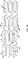
図3Aは、本発明のステントの実施形態の拡張前のモードの略図である。
図3Bは、本発明のステントの実施形態の拡張後の略図である。
図4Aは、本発明のステントの実施形態の寸法の入った略図である。
図4Bは、図4Aの略図の部分拡大図である。
図5は、拡張後のモードにおけるテーパした直径を備えた本発明のステントの実施形態の略図である。
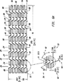
図6Aは、補強拡張コラムを備えた本発明のステントの実施形態の略図である。
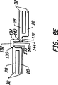
図6Bは、図6Aの実施形態の斜視図である。
図7Aは、ストラット接合部の可撓性を高めるためにストラット接合部のところに逃げ切込みを入れた本発明のステントの実施形態の略図である。
図7Bは、図7Aの実施形態の部分拡大図である。
図7Cは、図7Aの実施形態に従って2つの拡張ストラット対を互いに接合する単一の連結ストラットの拡大図である。
図8Aは、本発明の連結ストラットと接合ストラットの別の幾何学的形状を示す略図である。
図8Bは、本発明の連結ストラットと接合ストラットの別の幾何学的形状を示す略図である。
図8Cは、本発明の連結ストラットと接合ストラットの別の幾何学的形状を示す略図である。
図8Dは、本発明の連結ストラットと接合ストラットの別の幾何学的形状を示す略図である。
図8Eは、本発明の連結ストラットと接合ストラットの別の幾何学的形状を示す略図である。
図9は、本発明のステントの送達方法を示す送達用バルーンカテーテルの略図である。
詳細な説明
本発明の第1の実施形態が、図1A、図1B、図1C、図2A及び図2Bに示されている。図1Aを参照すると、非拡張状態の細長い中空管状ステント10が示されている。基端部12及び末端部14は、ステント10の長手方向長さ16を定めている。ステント10の長手方向長さ16は、100mm以上という長い長さのものであるのがよい。基端側開口部18及び末端側開口部20は、ステント10の内腔22に通じている。ステント10は、シーム又は溶接接合部のない単一片のものであっても、或いは多数の片からなっていてもよい。
ステント10は、散在する連結ストラットコラム26によって互いに連結された2〜50以上の拡張コラム又はリング24で構成されている。ストラット10の基端部12の最初のコラムと末端部14の最後のコラムは、拡張コラム24である。
拡張コラム24は、一連の拡張ストラット28と接合ストラット30で形成されている。拡張ストラット28は、少なくとも一部がステント10の長手方向軸線の方向に延びるように構成された薄くて細長い部材である。外向きの外力が拡張バルーン又は他の手段によって内側からステント10に及ぼされると、拡張ストラット28は、これらがいっそう円周の方向に、即ち円筒形ステント10の表面に沿って且つその長手方向軸線に垂直に延びるように向きが変わる。拡張ストラット28の向きが変わることにより、ステント10は拡張した円周長さ及び直径を有する。図1Aでは、非拡張状態のステント10の拡張ストラット28は、ステント10の長手方向軸線に実質的に平行に延びるように見える。
拡張ストラット28は、接合ストラット30によって互いに接合されて、複数の拡張ストラット対32が形成されている。拡張ストラット対は、閉鎖端部34及び開放端部36を有している。追加の接合ストラット30が、隣り合う拡張ストラット対32の拡張ストラット28を互いに接合して、拡張ストラット28がこれらの基端部と末端部のところで交互に隣の拡張ストラット28に接合されて拡張コラム24が形成されるようになっている。各拡張コラム24は、複数の、代表的には8〜20、20〜60又はこれ以上の拡張ストラット28を有している。
連結ストラット38が隣接の拡張コラム24を互いに連結して、各々がステント10の周囲の周りに延びる一連の散在した状態の連結ストラットコラム26を形成している。各連結ストラット38は、拡張コラム24内の一対の拡張ストラット28を隣の拡張コラム24内の隣の一対の拡張ストラット28に接合している。図1Aのステント10の場合、拡張コラム24内の拡張ストラット28の数と連結ストラットコラム26内の連結ストラット38の数との比は2:1であるが、この比は一般にx:1であり、ここでxは2よりも大きく又はこれよりも小さい。さらに、図1Aのステント10は、基端部12の拡張コラム24で始まり、末端部14の拡張コラム24で終わっているので、もし1コラム当たりに存在する拡張コラム24の数がn個、拡張ストラット28の数がm個であれば、連結ストラットコラム26の数は(m−1)個であり、連結ストラット38の数はn(m−1)/2個であろう。
各拡張コラム24内の拡張ストラット28と比べて、各連結ストラットコラム26内の連結ストラット38の数を減少させると、ステント10は長手方向に可撓性を持つことができる。長手方向の可撓性を一段と増大させるには、幅の狭い連結ストラットを用い、ステントが生来の状態の血管内の曲がり部の周りに移動する際のステントへの追加の可撓性及び柔軟性を与える。
ステント10のストラット相互間の開放空間の少なくとも一部は、非対称セル空間40を形成している。セル空間は、拡張ストラット28、連結ストラット38又は接合ストラット30を含むステントストラットのうちの一つ又はこれらの組合せにより完全に包囲されたステント10の表面上の空の領域である。非対称セル空間40は、幾何学的な対称性を有しておらず、即ち回転対称をなすわけでも、線対称をなすわけでも、回転対称且つ線対称をなすわけでも、或いは他の対称をなすわけでもない。
図1Aの非対称セル空間40は、第1の拡張コラム24の第1の拡張ストラット対32、第1の連結ストラット38、隣の拡張コラム24の第2の拡張ストラット対32、第1の接合ストラット30、第2の連結ストラット38及び第2の接合ストラット30で包囲されている。さらに、非対称セル空間40の拡張ストラット対32は、円周方向にずれているのがよく、即ち、同一直線上にはない長手方向軸線を有すると共に向かい合った開口端部36を有するのがよい。拡張ストラット対32の2つの拡張ストラット相互間の空間は、ループスロット42と呼ばれている。
図1Bは、ステント10の内腔22、半径44及びステント壁46を示している。ステント壁46は、拡張ストラット28、連結ストラット38及び接合ストラット30を含むステントストラットから成っている。
図1Cは、ステント10の基端部12、末端部14、長手方向長さ16、内腔22及びステント壁46を示している。内腔22は、ステント10の円筒形表面を形成するステント壁46によって包囲されている。
次に、図2A及び図2Bを参照すると、ステント10の接合ストラット30は、拡張ストラット28に対して角度をなして延びているように見え、拡張ストラット対32中の一拡張ストラット28と小さな角度48をなし、拡張ストラット対32の他の拡張ストラット28と大きな角度50をなしている。小さな角48は、90°未満であり、大きな角50は90°よりも大きい。接合ストラット30は、ステント10の長手方向軸線に沿って長手方向に且つステント10のその長手方向軸線に対して垂直なその表面に沿って円周方向に延びている。
所与の拡張コラム24内の隣り合う拡張ストラット28相互間の拡張ストラット離間距離52は、図2A及び図2Bのステント10では一定であるが、一定ではない離間距離を用いてもよい。拡張ストラット離間距離52は種々のものであってよく、例えば拡張コラム24中の隣り合う拡張ストラット28相互間の離間距離52は、小さな離間距離と大きな離間距離が交互になっていてもよい。さらに、単一の拡張コラム24内の離間距離52は、他のコラム24の他の離間距離52と異なっていてもよい。
ループスロット42を形成する拡張ストラット離間距離52を変えると、その結果、ループスロットの幅が変わることになることは注目される。さらに、ループスロット42の長手方向軸線は、隣の拡張コラム24のループスロット42の長手方向軸線と同一直線上にある必要はなく、或いはこれと平行である必要はない。図2A及び図2Bは、同一直線上に位置したループスロット42及び互いに平行な隣接したループスロット42が形成されるような拡張ストラット28の配置状態を示しているが、同一直線状に位置しておらず、しかも平行ではないループスロット42も使用できる。
さらに、ループスロット42の形状は、単一又は多数の拡張コラム24のループスロットを通じて同一である必要はない。ループスロット42の形状を変えるには、拡張ストラット28及び/又はループスロット42の境界を画定する拡張ストラット対32の拡張ストラット28を相互に連結する接合ストラット30の向き又は物理的寸法を変えるのがよい。
連結ストラット38は、一拡張コラム24内の拡張ストラット対の末端部を第2の拡張コラム24内の隣の拡張ストラット対32の基端部に連結することにより、隣り合う拡張コラム24を互いに結合している。図2A及び図2Bの連結ストラット38は、2つの直線部分で形成され、第1の直線部分54の末端部が第2の直線部分56の基端部に接合されて第1の傾斜角58が形成されている。
連結ストラット38の第1の直線部分54は、接合ストラット30が拡張ストラット28と小さな角度48をなす箇所で拡張ストラット28に接合されている。第1の直線部分54は、接合ストラット30まで実質的に同一直線上に延び、接合ストラット30のラインを拡張コラム24相互間の空間内へ継続させている。第1の直線部分54の末端部は、第2の直線部分56の基端部に接合されて傾斜角58を形成している。第2の直線部分56は拡張ストラット28と実質的に平行に延び、その末端部が隣の拡張コラム24内の接合ストラット30に繋がっている。第2の直線部分56の末端部は、接合ストラット30が拡張ストラット28と小さな角度48をなす箇所で拡張ストラット28に取り付けられている。さらに、接合ストラット30は、第1の傾斜角の幅と同一であってもよく、或いは異なっていてもよい幅と第2の傾斜角を有してもよい。
図2A及び図2Bは、ステント10の長手方向軸線に対して傾斜した連結ストラット38及び接合ストラット30を示しており、これら傾斜ストラットの円周方向における向きは、或るコラムとその隣のコラムで交互になっている。円周方向の向きとは、ステント10の表面の周りの傾斜ストラットの巻回方向のことである。連結ストラットコラム26中の連結ストラットの第1の直線部分54の円周方向における傾斜の向きは、その隣の連結ストラットコラム26中の連結ストラットの第1の直線部分54の円周方向における傾斜の向きとは逆である。同様に、拡張コラム24中の接合ストラット30の円周方向における傾斜の向きは、その隣の拡張コラム24中の接合ストラット30の円周方向における傾斜の向きとは逆である。連結ストラット38の円周方向における傾斜の向きと接合ストラット30の円周方向における傾斜の向きを交互にすることにより、送達及び拡張中におけるステント10の軸方向のそりが防止される。連結ストラット38又は接合ストラット30、或いはこれら両方について交互ではない他の傾斜の向きのパターンを用いてもよい。
図3A及び図3Bは、それぞれ本発明のステントを非拡張状態及び拡張状態で示す略図である。ステントは設計上、ステント10をあたかもその長手方向軸線に平行に長手方向に切断して平べったくしたかのように平らな投影像として示されている。連結ストラット38は、ピボット点60のところに傾斜角58を形成する第1の直線部分54と第2の直線部分56から成る。非対称セル空間40が、拡張ストラット対32、連結ストラット38及び接合ストラット30によって形成されている。多数のからみ合った状態の非対称セル空間40が、設計パターンを構成している。
ステントを拡張させると(図3B参照)、拡張ストラット対32はそれらの開放端部36のところで広がり、拡張ストラット28の長さは円筒形ステントの長手方向軸線に沿って短縮する。拡張の際の拡張ストラット28の長手方向短縮に対して、連結ストラット38は長手方向に伸長する。拡張の際に傾斜角58が大きくなると、連結ストラット38が真っ直ぐになると共に結合状態の拡張ストラット対32相互間の距離が長くなる。結合状態の拡張ストラット対32相互間の距離が長くなると、拡張ストラット28の長手方向の短縮が実質的に補償される。かくして、ステントは非拡張状態及び拡張状態において実質的に一定の長手方向長さを有する。
ステントが拡張すると、各拡張コラム24は、円周方向に引き伸ばされるようになり、ストラット相互間の空間が拡大する。拡張段階で真っ直ぐにされた連結ストラット38により拡張コラム24が相互に連結されることによって、ステント10には高い半径方向支持強度が与えられる。ステント10全体は拡張すると、引き伸ばされた拡張コラム24と連結ストラットコラム26から成る連続チェーンメッシュの状態に結合され、軸方向と半径方向の両方向の潰れに抵抗する非対称の相互にからみ合ったセルの幾何学的形状が形成される。ステントが拡張すると、ステントの剛性及び疲れ許容度が増大する。
加うるに、ピボット点60のところで連結ストラット38が効果的に曲がったり真っ直ぐになることにより、ステントの長手方向の可撓性が増大することができる。ステントを長手方向に曲げるためには、連結ストラット38のうち少なくとも幾つかがそれらの接平面内で曲がるようにする。特定の連結ストラット38の接平面とは、その連結ストラット38のところでのステントの円筒形表面に実質的に接する平面をいう。連結ストラット38の幅は代表的には、厚さの2〜4倍以上であり、これにより連結ストラット38は、これらの接平面内で曲がると比較的不撓性になる。しかしながら、連結ストラット38のピボット点60は、連結ストラット38に一層曲がりやすい可撓性の接合部を提供し、ステントの長手方向可撓性が高くなる。
図4A及び図4Bを参照すると、本発明のステント10の第1の実施形態が示されている。この変形例では、ステント10は、長さ16が33.25mmであり、圧着されておらず且つ拡張されていない状態での周囲長さ88は5.26mmである。15個の拡張コラム24の間には連結ストラットコラム26が散在している。各拡張コラム24は、6つの拡張ストラット対32を形成する接合ストラット30により基端部と末端部のところで交互に接合された12個の拡張ストラット28から成る。拡張ストラット28は、円筒形ステント10の長手方向軸線に平行に整列している。接合ストラット30は、拡張ストラット対32のそれぞれの拡張ストラット28と小さい角度48及び大きい角度50をなしている。隣り合う拡張コラム24は、円周方向における傾斜の向きを交互にした接合ストラット30を採用している。
第1の実施形態のこの変形例では、拡張ストラットの幅62は0.20mm、拡張ストラットの長さ64は1.51mm、連結ストラットの幅66は0.13mmである。同一拡張コラム24中の第1の拡張ストラット28の外縁から第2のその隣の拡張ストラット28の外縁までの距離68は、0.64mmであり、0.24mmのループスロットの幅70が残されている。
第1の実施形態のこの変形例では、連結ストラット38は、第1の傾斜した直線部分54を傾斜角58のところで第2の直線部分56に接合したものである。第1の直線部分54は、第2の直線部分54よりも僅かに長く、その基端部が拡張コラム54内の拡張ストラット28に取り付けられている。拡張ストラット28への第1の直線部分54の基端部の取付けは、接合ストラット30が拡張ストラット28と小さな角48をなす箇所で行われている。第1の直線部分54は、接合ストラット50に実質的に同一直線上に延びて、その末端部が第2の直線部分56の基端部に取り付けられて傾斜角58が形成されている。第2の直線部分56は、拡張ストラット28に対して実質的に同一直線上に延び、その末端部が隣の拡張コラム24の拡張ストラット28に取り付けられている。かかる取付けは、拡張ストラット28が接合ストラット30と小さな角48をなす箇所で行われている。接合ストラット30と模すの第1の直線部分54は、隣り合うコラム相互間で交互の円周方向の向きをなして傾斜している。
小さな角度48が形成される箇所における連結ストラット38と拡張ストラット28との接合は、非拡張状態のステントの表面を流線形にすると共に引っ掛かりの生じる恐れのある箇所を最小限に抑えることにより、ステント10のスムーズな送達を助けている。かくして、血管中の標的部位へのステント10の剥き出し状態での送達の結果として、ステント10が血管中の曲がり部及び湾曲部を通って送り進められているときの引っ掛かりが最小限に抑えられることになる。ステント10は、送達用カテーテルに取り付けられた状態で血管内を前後に移動しているときに可撓性のある管状の橇(そり)のような挙動を示し、曲がりくねった血管及び血管の管腔内部のアテローム硬化によるプラークによって生じた大きさが不揃いのこぶ状突起を乗り越えて摺動する。
図4A及び図4Bのステント10は、完全に拡張されると、許容レベルの半径方向支持強度及び疲労許容度を維持した状態で最高5.0mmの内径を有する。圧着状態のステントの外径は、その下に位置する送達バルーンプロフィールの条件に応じて1.0mm以下という小さなものであるのがよい。もしステントの送達が標的部位の予備拡張を行わないで試みられる場合には圧着状態における外径が小さいということが特に重要である。ステントが送達用バルーン上に最適状態で圧着されると、圧着状態のステントの表面は滑らかであり、血管中の前進又は後退中、ステントの引っ掛かりが生じないようになる。
図5は、本発明の第2の実施形態を示しており、かかる実施形態では拡張形態のステント10は、基端部12から末端部14へ漸次テーパを有している。拡張ストラット28の陰影をつけたセグメント72,74,76,78,80,82,84は、除去されるべき拡張ストラット28の領域を表している。陰影のついたセグメント72,74,76,78,80,82,84の除去により、ステント10は拡張されたときにゆるやかなテーパを呈することになり、末端部14は基端部12よりも小さな拡張直径を有する。所与の拡張コラム24のところにおけるステント10の拡張直径の縮み度は、その拡張コラム24のところにおける除去されたセグメント72,74,76,78,80,82又は84の長さに比例するであろう。拡張ステント10では、短くされた拡張ストラット28は、ステントの円周に沿って短くなった成分を有し、その結果、円周長さ及び直径が短くなる。テーパした直径部分を、ステント10の長さに沿ってどこかに位置決めするのがよく、テーパを幾分ゆるやかにするには、所与の拡張コラム24中の拡張ストラット28の適度に大きな又は小さな部分を除去するのがよい。テーパ付けは、12mm以上の長いステントにおいて特に重要である。というのは、血管のテーパは長い長さにわたって一層顕著だからである。一定のステント直径を備えた長いステントは、短い領域にわたって標的血管の直径にしかマッチさせることができない。近位の血管のサイズがステント直径とマッチすれば、ステントの拡張末端部は、生来の血管にとっては大きすぎることになり、ステントの拡張により遠位の血管の内膜解離を引き起こす場合がある。他方、もし遠位血管のサイズがステント直径とマッチしていれば、拡張ステントの基端部は、血管の管腔の内側にセットするには小さすぎることになる。したがって、テーパした拡張直径を備えるステントを提供することが望ましい。
テーパした拡張ステントを達成する別の方法は、ステントストラット、拡張ストラット、連結ストラット又は接合ストラットの剛性を変えてストラットの剛性がステントの長さ方向に沿って変化するようにすることである。ストラットの剛性を変えるには、長さ、幅又は厚さを変えるか、補剛材料を追加するか、化学的又は機械的手段を用いてステント材料の物理的性質を変えるか、或いはステントの周りに一つの又は一連の弾性要素を施す。
テーパした直径のステントを使用すると共にテーパした直径のステントの送達及び配備を行うためにこれとマッチングしたテーパのバルーンカテーテルを製作するのが理想的である。テーパした直径のステントと共に用いられるマッチしたテーパ付きバルーンカテーテルを用いる方法は、本発明の範囲に属する。
また、テーパしたバルーンを用いて非テーパステントを拡張させても、テーパした拡張ステントが得られることになるが、ステントから金属は除去されないのでステントは不完全な拡張の結果としてテーパする。したがって、ステントはテーパ端部のところで金属フラクションが多く、その結果、急性血栓症の恐れが高くなる。金属フラクションとは、ステントストラット材料で覆われた拡張ステントの表面の割合である。図5に示すように拡張ストラットを短縮させることにより、その長さ方向に沿って実質的に一定の金属フラクションを備えたテーパ拡張ステントが得られる。
図6A及び図6Bに示す本発明の第3の実施形態は、ステント10の長さ方向に沿って配置された多数の補強拡張コラム86を有している。補強コラム86は、ステントの長さ方向に沿って配置されていて、スンテト10に追加の局部的半径方向支持強度及び剛性を与えている。追加の強度及び剛性は、送達中と配置後の両方においてステントの変形を防止する上でステントの両端で特に重要である。送達中、ステント端部は、血管の壁に引っ掛かる場合があり、場合によっては非拡張状態のステントを変形させると共にその拡張特性を変える。ステントを配置した後、ステントの端部は、これらが血管の壁にしっかりと当接したままになるよう剛性であることが重要であり、さもなければ、その後のカテーテルの操作手順の際、カテーテル又はガイドワイヤがスンテトの端部に引っ掛かってステントを血管の壁から引き離す場合があり、場合によっては血管を損傷させると共に、或いは閉塞させる場合がある。
図6A及び図6Bに示すステント10の第3の実施形態の特定の変形例は、20.70mmの長さ16及び5.26mmの非圧着且つ非拡張周囲長さ88を有している。ステント10は、6個の拡張コラム24及び3個の補強拡張コラム86から成り、各々それぞれ各コラムはそれぞれ、12の拡張ストラット28又は補強拡張ストラット90から成る。補強拡張コラム86は、各端に1つ且つステント10の長さ方向に沿って1つ配置されている。拡張ストラットの幅62は0.15mm、補強拡張ストラットの幅92は0.20mmであり、連結ストラットの幅66は0.10mmである。接合ストラット30と拡張ストラット28により形成される小さな角度48は75°であり、補強接合ストラット96と補強拡張ストラット90により形成される小さな角度94は60°である。
補強拡張ストラット86の他の配置構成、例えば補強拡張コラム86をステントの両端にだけ、一端にだけ、或いはステントの長さ全体にわたり多数の箇所に設けてもよく、これは本発明の範囲に属する。また、適当な拡張コラム24,86中の拡張ストラット28及び補強拡張ストラット90を短くすることにより、テーパを補強状態のステント10中へプログラムしてもよい。
図7A、図7B及び図7Cに示す本発明の第4の実施形態は、第3の実施形態と類似しているが、逃げ切込み98,100という別の特徴を備えている。逃げ切込みは、通常は多数のストラットが連結されている接合部のところでストラットから金属を除去した後の切込みである。逃げ切込みを設けることによりストラット又は接合部に沿って薄い且つ狭い領域が形成されるのでストラット又は接合部の可撓性が増大する。逃げ切込み98は、連結ストラット38の第1の直線部分54と拡張ストラット28との間に形成された接合部に形成される。逃げ切込み100は、連結ストラット38の第2の直線部分56と拡張ストラット28との間の接合部のところに形成される。逃げ切込みを配置することにより、非拡張状態のステントに追加の可撓性が与えられる。逃げ切込みを他方の接合部のところに配置してもよく、そして上述の実施形態のうち任意のものに組み込んでもよい。
図8A、図8B、図8C、図8D及び図8Eは、上述の実施形態のうちの任意のものに用いることができる連結ストラットの幾つかの変形例を示している。図8Aは、隣の拡張コラム中の2つの円周方向にずれた拡張ストラット対32を接合する丸いループ連結ストラット38を示している。各拡張ストラット対32の拡張ストラット28は、接合ストラット30によって互いに接合されている。接合ストラット30は、これらが連結する拡張ストラット28と小さな角度48及び大きな角度50をなすように傾斜している。丸いループ連結ストラット38は、小さい角度が拡張ストラット28と接合ストラット30との間に形成される箇所で拡張ストラット28に繋がっている。基端部102及び末端部104のところにおける丸い連結ストラット38の勾配は、実質的に拡張ストラット28の対を連結する接合ストラット30の勾配と実質的に一致している。かくして、丸いループ連結ストラット38は接合ストラット30にスムーズに合体している。さらに、丸いループ連結ストラット38は、第1の曲率半径106及び第2の曲率半径108を有している。
図8Bの設計では、丸いループ連結ストラット38は、隣り合う拡張コラム中の2つの円周方向にずれた拡張ストラット対32を接合している。各拡張ストラット対32の拡張ストラット28は、接合ストラット30によって互いに接合されている。接合ストラット30は、これらが連結する拡張ストラット28に対して直角をなしている。丸いループ連結ストラット38は、接合ストラット30と同一の箇所で拡張ストラット28に繋がっている。丸い連結ストラット38は第1の曲率半径106及び第2の曲率半径108を有していて、円周方向にずれた拡張ストラット対32を互いに連結するようになっている。
図8Cの設計では、連結ストラット38は、隣り合う拡張コラム中の2つの円周方向にずれた拡張ストラット対32を互いに接合している。各拡張ストラット対32の拡張ストラット28は、接合ストラット30によって互いに接合されている。接合ストラット30は、これらが連結される拡張ストラット28と小さな角度48及び大きな角度50をなすように傾斜している。連結ストラット38は、小さな角度48が拡張ストラット28と接合ストラット30との間に形成される箇所で拡張ストラット28を互いに連結している。
連結ストラット38は、2つの傾斜角116,118を形成する3つの直線部分110,112,114で構成されている。直線部分110の基端部は、接合ストラット30が拡張ストラット28と小さな角48をなす箇所で拡張ストラット28に取り付けられている。直線部分110は、接合ストラット30に対して実質的に同一直線上に延び、その末端部が直線部分112に取り付けられて、傾斜角116を形成している。直線部分112は、直線部分110に対して角度をなして延びていて、直線部分112が拡張ストラット28に実質的に平行であるようになっており、この直線部分112はその末端部が直線部分114の基端部に連結されて、傾斜角118を形成している。直線部分114は、隣の拡張ストラット対32の接合ストラット30と実質的に同一直線上にあるように角度をなして延びている。直線部分114はその末端部が隣の拡張ストラット対32の拡張ストラット28に、接合ストラット30が拡張ストラット28と小さな角度48をなす箇所で取り付けられている。
図8D及び図8Eの設計では、連結ストラット38は、隣り合う拡張コラム内の2つの円周方向にずれた拡張ストラット対32を互いに接合している。各課す対32中の拡張ストラット28は、接合ストラット30により互いに接合されている。接合ストラット30は、これらが繋がっている拡張ストラット28に対して直角をなしている。連結ストラット38は、接合ストラット30と同一の箇所で拡張ストラット28に連結されている。
図8D及び図8Eの連結ストラット38は、多数の連結ストラット部分で構成されており、これら連結ストラット部分は、拡張ストラット対32をその隣の拡張ストラット対32に結合する多数の傾斜角を備えたぎざぎざの連結ストラット38を形成するよう端と端とが連結されている。図8Dの連結ストラットは、2つの傾斜角126,128が形成される3つの連結ストラット部分120,122,124で構成され、これに対して図8Eの連結ストラットは、3つの傾斜角138,140,142が形成される4つの連結ストラット部分130,132,134,136で構成されている。加うるに、連結ストラット部分134は、連結ストラット部分136に代えて点線で示した連結ストラット部分144を用いることにより設計変更が行われており、それにより連結ストラット38の考えられる別の幾何学的形状が得られている。
当業者であれば、連結ストラットと接合ストラットについて本発明の範囲に属する多くの配置例が考えられ、上述した例は排他的に挙げられたものではないことが分かろう。
本発明のステントは、ステント設計の融通性により、非冠状血管、大動脈、及び無血管の管状体内器官にも使えるが、冠状血管用途に最適である。
代表的な冠状脈管用ステントは、2.5mm〜5.0mmの拡張直径を有している。しかしながら、大きな半径方向強度及び疲労許容度を備えていて、5.0mmの直径まで拡張するステントは、直径の小さな血管に用いられる場合には許容限度を越えるほど高いステント金属フラクションを有することがある。もしステント金属フラクションが高ければ、血栓症や再狭窄の恐れが強くなろう。金属フラクションが同一であっても、小さな管腔直径の血管は大径のものよりも血栓症の発生率が高くなりがちである。したがって、冠状用途には少なくとも2つの互いに異なる種類のステント、即ち、直径が2.5mm〜3.0mmの血管に用いられる小径血管用ステント及び直径が3.0mm〜5.0mmの血管に用いられる大径血管用ステントを提供することが好ましい。かくして、小径血管と大径血管は両方共、適当なサイズのステントを用いて治療されると、互いに類似した理想的な金属フラクションのステントを収容することになろう。
本発明のステントは、CAM駆動型レーザ切断システムを用いてステンレス鋼製管からステントパターンを切り出して製造できる。粗切断ステントを好ましくは電解研磨して表面欠陥及び鋭利なエッジを除去する。ステントの他の製造方法、例えばEDM、光電エッチング又は他の方法も使用できる。ステントの構成材料として任意適当な材料を使用でき、かかる材料としては、他の金属及びポリマーが挙げられる。ただし、これら材料が必須の構造強度、可撓性、生物学的適合性及び拡張性を備えることを条件とする。
ステントは代表的には、少なくとも一部がラジオパク(放射線不透過性)金属、例えば金、白金、タンタル又は他の適当な金属でめっきされる。ステントの両端部だけを局所めっき法でめっきするのが好ましいが、ステント全体又は他の領域をめっきしてもよい。両端部をめっきする場合、ステントの各端部の1〜3又はこれ以上の拡張コラムをめっきしてステントの両端をマーク付けし、ステント装着手順の際にX線透視検査でこれらを識別できるようにする。ステントを両端部だけめっきすることにより、性能特性又は表面調整特性を備えたステントフレームのラジオパクめっき材料の干渉が最小限に抑えられる。さらに、めっき材料の所要量が少なくなり、ステントの材料費が安くなる。
めっき後、ステントを、通常は当該技術分野で周知の洗剤、食塩水及び超音波手段を用いてクリーニングする。次に、ステントを品質管理のために検査し、送達バルーンカテーテルに組み付け、適正に包装してラベルを貼り、殺菌する。
ステントを単独で販売してもよく、或いは図9に示すように予め取り付けられた送達バルーンカテーテル組立体として販売してもよい。図9を参照すると、ステント10は、送達バルーンカテーテル組立体150の末端部148のところに位置した折り畳み状態のバルーン146上にクリンプ又は圧着されている。組立体150は、基端部アダプタ152、カテーテルシャフト154、バルーンチャンネル156、ガイドワイヤチャンネル158、バルーン146及びガイドワイヤ160を有している。バルーン146は、拡張状態において基端部から末端部までテーパし、或いは湾曲し、又はテーパすると共に湾曲したものであってもよい。さらに、ステント10は、拡張状態において、テーパしていないものであってもテーパしているものであってもよい。
代表的には、ガイドワイヤ160を静脈又は動脈内へ挿入し、標的部位まで送り進める。次に、カテーテルシャフト154をガイドワイヤに沿って前進させてステント10及びカテーテル146を標的部位のところの適所に位置決めする。いったん適所に配置すると、バルーン146をバルーンチャンネル156を介して膨らませてステント10を拡張させて圧着状態から拡張状態にする。拡張状態では、ステント10は血管に対して所望の副木的支持手段となる。ステント10をいったん拡張すると、バルーン146を萎ませてカテーテルシャフト154、バルーン146及びガイドワイヤ160を患者から取り出す。
本発明のステントを10mm以下という短い長さにしてもよく、或いは100mm以上という長い長さにしてもよい。しかしながら、長いステントを用いる場合、ステントをこれらの展開位置に拡張させるためには、一般に、これとマッチした長さの送達カテーテルバルーンが必要になろう。長いステントは、標的血管によるが、この展開のためには湾曲した長いバルーンを必要とする場合がある。血管の自然な湾曲状態に一致した湾曲状態のバルーンは、ステント展開の際に血管に加わる応力を減少させる。これは湾曲した冠状血管内でのステント処置を必要とする多くの冠状血管用途に特に重要である。かかる湾曲バルーンの使用は、本発明の範囲に属する。
本発明の好ましい実施形態の上記説明は例示の目的でなされたものである。かかる説明は、排他的ではなく、本発明を開示した形態そのものに限定するものではない。当業者であれば多くの設計変更及び改造を行いうることは明らかである。本発明の範囲は特許請求の範囲の記載及びその均等範囲に基づいて定められる。Background of the Invention
Field of Invention
The present invention relates to an intravascular stent, and more particularly to an intravascular stent that is easy to introduce into a tortuous portion of a blood vessel.
Explanation of related technology
Angioplasty (coronary or general angioplasty) has advanced in the art and has become the most effective means of regenerating stenotic blood vessels. In the early 1980s, angioplasty was first used for coronary clinical methods and has since proven to be an effective alternative to conventional bypass tissue transplantation procedures. Angioplasty using balloon catheters remains the most reliable and most practical interventional procedure. Other ancillary techniques, such as laser treatment or directional or rotational arthrotomy, have limited effectiveness, or angioplasty using a balloon to complete the intended procedure Has been found to be either one that uses Restenosis after angioplasty using a balloon is the most serious drawback and is particularly prominent in the coronary artery system.
Many regimens have been devised to control stenosis, but the degree of success has been limited. Such regimens include laser-based treatment and directional or rotational arthrotomy. However, it is noteworthy that the rate of restenosis after angioplasty is reduced by intravascular stent implantation. Intravascular stent implantation procedures typically use balloon angioplasty to pre-expand the target vessel, then deploy the stent and expand the stent to support the expanded vessel wall from within To be.
Intravascular stents provide splint scaffolding for the vessel lumen. The splint support of the vessel wall by the stent (a) prevents elastic return of the expanded vessel wall, and (b) prevents residual stenosis of the vessel (typically occurring during balloon angioplasty). (C) keep the diameter of the stented vessel segment slightly larger than the native non-occluded vessel located proximal and distal to the vessel segment, and (d) modern clinical Helps reduce the incidence of restenosis as shown in the data. Following the performance of angioplasty, the rate of restenosis of stent-retained blood vessels is determined by restenosis of blood vessels that have not undergone stent support or have been treated with another method (including drug treatment and other methods described above). It has been found that it is significantly lower than the incidence.
Another advantage of vascular stent support is the expected reduction in emergency bypass surgery due to angioplasty. Stent support has proven to be effective in some cases in treating impending blood vessels during angioplasty. Stent support can also control and stabilize unstable local intima tears caused by normal actions during angioplasty. In some cases, balloon angioplasty can be successfully patented by stent implantation, even if the vascular lesions are not sufficiently expanded or less than optimal.
There have been serious anticoagulant problems with stent implantation methods, especially in the coronary arteries early in the development phase. However, anticoagulant technology has evolved since then and has become easier and more effective. Good and easy-to-use regimens (including simple outpatient anticoagulant treatments as such regimens) are constantly being introduced, resulting in shorter hospital stays for patients treated with stents It was.
An example of a patent related to a conventional stent is US Pat. No. 5,102,417 (hereinafter referred to as “Palmaz patent”). The stent described in the Palmaz patent consists of a series of elongate tubular members that have a plurality of slots disposed substantially parallel to their longitudinal axes. The tubular members are connected to each other by at least one flexible connector member.
The unexpanded tubular member of the Palmaz patent is too stiff, so its practical application is limited to short lengths. In an embodiment of a multi-link design with a flexible connector that connects a series of tubular members together, a long stent cannot travel along a tortuous vessel. Furthermore, the stiffness of the unexpanded stent increases the possibility of damaging the blood vessel during insertion. The shrinkage of the stent during insertion complicates the correct placement of the stent and reduces the area that the expanded stent can cover. Furthermore, there is no way to program the stent diameter along its longitudinal axis to obtain a tapered expanded stent, and no method is provided for reinforcing the end or other region of the stent.
Another example of a patent related to a conventional stent is WO96 / 03092 (hereinafter referred to as “Bran patent”). The stent described in the Blanc patent is formed of patterned shaped tubes, which have first and second serpentine patterns. The even-numbered and odd-numbered winding patterns are 180 ° out of phase, and the odd-numbered pattern occurs between every second even-numbered pattern. The second winding pattern extends perpendicular to the first winding pattern along the axis of the tube.
Adjacent first serpentine patterns are connected to each other by a second serpentine pattern to form a uniform distribution pattern as a whole. Due to the symmetrical configuration with the first and second tortuous patterns with steep right-angle bends, the vessel wall is trapped during delivery. In addition, large turns in the second tortuous pattern are not completely straightened during expansion, reducing the stiffness and structural strength of the expanded stent. Further, there is no way to program the stent diameter along its longitudinal axis to obtain a tapered design stent, and no method is provided to reinforce the end or other region of the stent.
Conventional and other designs of these and other designs have various disadvantages to some degree. As such disadvantages, (a) the non-expanded stent has a high columnar rigidity and cannot adapt to the bent portion of the blood vessel, and (b) the structural strength of the non-expanded stent in the radial and axial directions. (C) the stent shrinks significantly during expansion, (d) the length of the stent is limited, (e) the expansion stent has a constant diameter, and (f) the crimping characteristics. (G) the change in the surface of the unexpanded stent is rough.
There is a need for a stent with sufficient longitudinal flexibility to be able to travel through a tortuous vessel in an unexpanded state. Further, there is a need for a stent that is structurally strong in an unexpanded state so that the risk of damage or distortion during delivery is minimized. There is a further need for a stent that maintains substantially the same longitudinal length during expansion so that the coverage at the target site can be increased and proper placement of the stent can be easily performed. There is a further need for stents that are designed with longitudinal flexibility to allow long stents up to 100 mm to be safely delivered into tortuous vessels. There is a need for a stent shaped to expand to a variable diameter along the length of the stent so that a taper can be applied to the expanded stent, thereby matching the native taper of the target vessel. (I) Can be firmly crimped onto the dilatation balloon in a thin (low profile) state and in a flexible state, and (ii) crimped onto the delivery catheter to prevent catching on the vessel wall during delivery And (iii) at the end or middle, or both, so as to maintain the end of the stent in fixed contact with the vessel wall of the target vessel. There is a need for a stent with a reinforcing ring.
Summary of the Invention
Accordingly, it is an object of the present invention to provide a splint support means for the lumen of a blood vessel.
Another object of the present invention is to provide a stent that prevents vascular rebound after angioplasty.
Another object of the present invention is to provide a stent that keeps the vessel lumen large compared to results obtained using only balloon angioplasty.
Another object of the present invention is to provide a stent that reduces the shrinkage of the stent length when expanded.
Another object of the present invention is to provide a stent with increased flexibility when delivered to a selected site within a blood vessel.
Another object of the present invention is to provide a low profile stent when crimped onto the delivery balloon of the stent assembly.
It is another object of the present invention to provide a stent that reduces vessel wall damage.
It is another object of the present invention to provide a chain mesh stent that reduces “trapping” to blood vessels in tortuous or curved blood vessels.
The above and other objects of the present invention are achieved by providing a stent in an unexpanded state. The first expansion strut pair has first and second expansion struts located adjacent to each other. A joining strut of the first expansion strut pair joins the first expansion strut and the second expansion strut to each other at the end of the first expansion strut pair. The plurality of first expansion strut pairs form a first expansion column. A second expansion strut pair has first and second expansion struts located adjacent to each other. A joining strut of the second expansion strut pair couples the first expansion strut and the second expansion strut of the second expansion strut pair to each other at the proximal end of the second expansion strut pair. The plurality of second expansion strut pairs form a second expansion column. The first connecting strut has a proximal head and a distal tail. The proximal head is coupled to the distal end of the first expansion strut pair in the first expansion column, and the distal tail is at the proximal end of the second expansion strut pair in the second expansion column. Are combined. The plurality of first connection struts form a first connection strut column that connects the first extension column and the second extension column to each other. The distal tail extends in a first lateral direction relative to the longitudinal axis of the proximal head to form a first tilt angle. The stent has first and second expansion struts in which a third expansion strut pair is located adjacent to each other. A third joint strut of the third expansion strut joins the first expansion strut and the second expansion strut at the proximal end of the third expansion strut pair. The plurality of third extension strut pairs form a third extension column. The first expansion strut of the first expansion strut pair in the first expansion column is parallel to and offset from the longitudinal axis of the first expansion strut of the second expansion strut pair in the second expansion column. Having a longitudinal axis. The second expansion strut of the third expansion strut pair in the third expansion column is parallel to and offset from the longitudinal axis of the first expansion strut of the second expansion strut pair in the second expansion column. Having a longitudinal axis. The second connecting strut includes a proximal head and a distal tail. The proximal head of the second connecting strut is coupled to the distal end of the second expansion strut pair in the second expansion column. The distal tail of the second connecting strut is coupled to the proximal end of the third expansion strut pair of the third expansion column. The plurality of second connection struts form a second connection strut column that couples the second extension column and the third extension column to each other. The distal tail of the second connecting strut is in a direction opposite to the first lateral direction with respect to the longitudinal axis of the proximal head of the second connecting strut so as to form a second tilt angle. It extends in a second lateral direction. The ratio of the number of expansion struts in the expansion strut column to the number of connection struts in the connection strut column is 2: 1. The first tilt angle reduces the degree of contraction of the stent between the first expansion column and the second expansion column when the stent is in the expanded state.
In another embodiment, the stent assembly has a balloon and an expandable stent disposed on the exterior of the balloon. The stent has a first expansion strut. The plurality of first expansion struts form a first expansion column. A plurality of second expansion struts form a second expansion column. A plurality of first connecting struts form a first connecting strut column. Each first expansion strut of the first expansion column is coupled to a second expansion strut of the second expansion column. The first connecting strut has a proximal end coupled to the distal end, and at least a portion of the first connecting strut has a first straight portion and a first tilt angle.
[Brief description of the drawings]
FIG. 1A is a side view of a pre-expansion mode of a stent embodiment of the present invention.
FIG. 1B is a cross-sectional view of an embodiment of the stent of the present invention.
FIG. 1C is a longitudinal cross-sectional view of an embodiment of the stent of the present invention.
FIG. 2A is a schematic illustration of a strut pattern of an embodiment of the stent of the present invention.
FIG. 2B is a development view of a part of the pattern of FIG. 2A.
FIG. 3A is a schematic representation of the pre-expansion mode of the stent embodiment of the present invention.
FIG. 3B is a schematic view after expansion of an embodiment of the stent of the present invention.
FIG. 4A is a schematic diagram with dimensions of an embodiment of the stent of the present invention.
FIG. 4B is a partially enlarged view of the schematic of FIG. 4A.
FIG. 5 is a schematic illustration of an embodiment of a stent of the present invention with a tapered diameter in the expanded mode.
FIG. 6A is a schematic illustration of an embodiment of a stent of the present invention with a reinforced expansion column.
FIG. 6B is a perspective view of the embodiment of FIG. 6A.
FIG. 7A is a schematic illustration of an embodiment of a stent of the present invention with a relief cut at the strut joint to increase the flexibility of the strut joint.
FIG. 7B is a partially enlarged view of the embodiment of FIG. 7A.
FIG. 7C is an enlarged view of a single connecting strut joining two expansion strut pairs together according to the embodiment of FIG. 7A.
FIG. 8A is a schematic diagram showing another geometry of the connecting struts and joint struts of the present invention.
FIG. 8B is a schematic diagram illustrating another geometric shape of the connecting struts and joint struts of the present invention.
FIG. 8C is a schematic diagram illustrating another geometry of the connecting struts and joint struts of the present invention.
FIG. 8D is a schematic diagram illustrating another geometry of the connecting struts and joint struts of the present invention.
FIG. 8E is a schematic diagram illustrating another geometric shape of the connecting struts and joint struts of the present invention.
FIG. 9 is a schematic view of a delivery balloon catheter illustrating the stent delivery method of the present invention.
Detailed description
A first embodiment of the present invention is shown in FIGS. 1A, 1B, 1C, 2A and 2B. Referring to FIG. 1A, an unexpanded elongated hollow
The
The
The expansion struts 28 are joined together by
Connecting struts 38 connect
By reducing the number of connection struts 38 in each
At least part of the open space between the struts of the
The
FIG. 1B shows the
FIG. 1C shows the
2A and 2B, the
The expansion strut spacing 52 between adjacent expansion struts 28 in a given
It is noted that changing the expansion strut separation distance 52 that forms the
Further, the shape of the
The connecting struts 38 connect
The first
2A and 2B show the connecting
3A and 3B are schematic diagrams showing the stent of the present invention in an unexpanded state and an expanded state, respectively. The stent is shown by design as a flat projection image as if the
When the stent is expanded (see FIG. 3B), the expansion strut pairs 32 expand at their open ends 36, and the length of the expansion struts 28 decreases along the longitudinal axis of the cylindrical stent. In contrast to the longitudinal shortening of the
As the stent expands, each
In addition, the effective bending and straightening of the connecting
4A and 4B, a first embodiment of the
In this variation of the first embodiment, the
In this modification of the first embodiment, the connecting
The joining of the connecting
The
FIG. 5 shows a second embodiment of the present invention in which the expanded
Another way to achieve a tapered expansion stent is to change the stiffness of the stent strut, expansion strut, connection strut or joint strut so that the stiffness of the strut varies along the length of the stent. To change the stiffness of the struts, change the length, width or thickness, add stiffening material, change the physical properties of the stent material using chemical or mechanical means, or around the stent One or a series of elastic elements.
Ideally, a tapered diameter stent should be fabricated using a tapered diameter stent and matched to deliver and deploy a tapered diameter stent. Methods using matched tapered balloon catheters used with tapered diameter stents are within the scope of the present invention.
Also, expanding a non-tapered stent using a tapered balloon will result in a tapered expanded stent, but since the metal is not removed from the stent, the stent will taper as a result of incomplete expansion. Therefore, the stent has many metal fractions at the tapered end, resulting in a high risk of acute thrombosis. Metal fraction is the percentage of the surface of the expanded stent that is covered with stent strut material. By shortening the expansion strut as shown in FIG. 5, a taper expansion stent with a substantially constant metal fraction along its length is obtained.
The third embodiment of the present invention shown in FIGS. 6A and 6B has a number of reinforced
A particular variation of the third embodiment of the
Other arrangements of reinforced expansion struts 86, such as reinforced
The fourth embodiment of the present invention shown in FIGS. 7A, 7B and 7C is similar to the third embodiment, but has another feature of relief cuts 98,100. A relief cut is a cut after the metal is removed from the struts, usually at a junction where a number of struts are connected. Providing the relief cuts increases the flexibility of the strut or joint because a thin and narrow area is formed along the strut or joint. A relief cut 98 is formed at the junction formed between the first
8A, 8B, 8C, 8D and 8E show several variations of connecting struts that can be used in any of the above-described embodiments. FIG. 8A shows a round
In the design of FIG. 8B, round
In the design of FIG. 8C, connecting
The connecting
In the designs of FIGS. 8D and 8E, the connecting
The connecting struts 38 of FIGS. 8D and 8E are composed of a number of connecting strut portions, which have a number of tilt angles that couple the
One skilled in the art will recognize that many examples of arrangements that fall within the scope of the present invention for connecting struts and splicing struts are possible, and that the above examples are not exclusive.
The stent of the present invention can be used for non-coronary, aortic, and avascular tubular internal organs due to the flexibility of the stent design, but is ideal for coronary applications.
A typical coronary stent has an expanded diameter of 2.5 mm to 5.0 mm. However, stents that have large radial strength and fatigue tolerance and expand to a diameter of 5.0 mm may have a stent metal fraction that is high enough to exceed acceptable limits when used on small diameter vessels. . If the stent metal fraction is high, the risk of thrombosis and restenosis will increase. Even with the same metal fraction, blood vessels with small luminal diameters tend to have a higher incidence of thrombosis than those with large diameters. Therefore, for coronary applications, it is used for at least two different types of stents, ie small diameter stents used for blood vessels with a diameter of 2.5 mm to 3.0 mm and blood vessels with a diameter of 3.0 mm to 5.0 mm. It is preferred to provide a large diameter vascular stent. Thus, both small and large vessels will receive ideal metal fraction stents similar to each other when treated with an appropriately sized stent.
The stent of the present invention can be manufactured by cutting a stent pattern from a stainless steel tube using a CAM-driven laser cutting system. The coarsely cut stent is preferably electropolished to remove surface defects and sharp edges. Other methods of manufacturing the stent, such as EDM, photoelectric etching or other methods can also be used. Any suitable material can be used as the constituent material of the stent, such materials including other metals and polymers. Provided that these materials have the necessary structural strength, flexibility, biocompatibility and expandability.
The stent is typically plated at least in part with a radiopaque metal such as gold, platinum, tantalum or other suitable metal. Although it is preferable to plate only both ends of the stent by the local plating method, the entire stent or other regions may be plated. When plating both ends, 1 to 3 or more expansion columns at each end of the stent are plated to mark both ends of the stent so that they can be identified by fluoroscopy during the stent loading procedure To. By plating the stent only at both ends, interference of the radiopac plating material of the stent frame with performance or surface conditioning properties is minimized. Furthermore, the required amount of plating material is reduced and the material cost of the stent is reduced.
After plating, the stent is usually cleaned using detergents, saline and ultrasonic means well known in the art. The stent is then inspected for quality control, assembled into a delivery balloon catheter, properly packaged, labeled and sterilized.
The stent may be sold alone or as a pre-attached delivery balloon catheter assembly as shown in FIG. Referring to FIG. 9, the
Typically, a
The stent of the present invention may be as short as 10 mm or less, or as long as 100 mm or more. However, when using long stents, a matching length of delivery catheter balloon will generally be required to expand the stent to these deployed positions. Long stents depend on the target vessel, but this deployment may require a long curved balloon. A curved balloon that matches the natural curved state of the vessel reduces the stress on the vessel during stent deployment. This is particularly important for many coronary applications that require stenting within curved coronary vessels. The use of such curved balloons is within the scope of the present invention.
The foregoing description of the preferred embodiment of the present invention has been made for purposes of illustration. Such description is not exclusive and is not intended to limit the invention to the precise form disclosed. It will be apparent to those skilled in the art that many design changes and modifications can be made. The scope of the present invention is determined based on the description of the claims and the equivalent scope thereof.
Claims (11)
互いに隣接して位置した第1及び第2の拡張ストラットと、接合ストラットとから成る第1の拡張ストラット対を有し、第1の拡張ストラット対の接合ストラットは、第1の拡張ストラットと第2の拡張ストラットを、第1の拡張ストラット対の末端部のところで互いに結合し、複数の前記第1の拡張ストラット対は、第1の拡張コラムを形成することと、
前記ステントは、互いに隣接して位置した第1及び第2の拡張ストラットと、接合ストラットとから成る第2の拡張ストラット対を更に有し、第2の拡張ストラット対の接合ストラットは、第2の拡張ストラット対の第1の拡張ストラットと第2の拡張ストラットを、第2の拡張ストラット対の基端部のところで互いに結合し、複数の前記第2の拡張ストラット対は、第2の拡張コラムを形成することと、
前記ステントは、基端側頭部及び末端側尾部を含む第1の連結ストラットを更に有し、基端側頭部は、第1の拡張コラム中の第1の拡張ストラット対の末端部に結合され、末端側尾部は、第2の拡張コラムの第2の拡張ストラット対の基端部に結合され、複数の第1の連結ストラットは、第1の拡張コラムと第2の拡張コラムを互いに結合する第1の連結ストラットコラムを形成し、末端側尾部は、第1の傾斜角を形成するよう基端側頭部の長手方向軸線に対して第1の横方向に延びることと、
前記ステントは、互いに隣接して位置した第1及び第2の拡張ストラットと、第3の接合ストラットとから成る第3の拡張ストラット対を有し、第3の拡張ストラット対の第3の接合ストラットは、第1の拡張ストラットと第2の拡張ストラットを第3の拡張ストラット対の基端部のところで結合し、複数の前記第3の拡張ストラット対は、第3の拡張コラムを形成することと、第2の拡張コラム中の第2の拡張ストラット対の第1の拡張ストラットは、第1の拡張コラム中の第1の拡張ストラット対の第1の拡張ストラットに対して周方向において離間し、且つ、第1の拡張コラム中の第1の拡張ストラット対の第1の拡張ストラットの長手方向軸線と平行な長手方向軸線を有し、第3の拡張コラム中の第3の拡張ストラット対の第2の拡張ストラットは、第2の拡張コラム中の第2の拡張ストラット対の第1の拡張ストラットに対して周方向において離間し、且つ、第2の拡張コラム中の第2の拡張ストラット対の第1の拡張ストラットの長手方向軸線と平行な長手方向軸線を有することと、
前記ステントは、基端側頭部及び末端側尾部を含む第2の連結ストラットを更に有し、基端側頭部は、第2の拡張コラム中の第2の拡張ストラット対の末端部に結合され、末端側尾部は、第3の拡張コラムの第3の拡張ストラット対の基端部に結合され、複数の第2の連結ストラットは、第2の拡張コラムと第3の拡張コラムを互いに結合する第2の連結ストラットコラムを形成し、末端側尾部は、第2の傾斜角を形成するよう基端側頭部の長手方向軸線に対し、前記第1の横方向とは逆の方向である第2の横方向に延びることと、
第1の連結ストラットの少なくとも一部は、第1の拡張ストラット対の接合ストラットに接合された第1の直線部分及び第2の拡張ストラット対の接合ストラットに接合された第2の直線部分を有し、第1の直線部分の末端部は第2の直線部分の基端部に接合されることと、
連結ストラットの第1の直線部分と拡張ストラットとの間に形成された接合部において形成された第1の逃げ切込みと、連結ストラットの第2の直線部分と拡張ストラットとの間の接合部において形成された第2の逃げ切込みを更に有することと、
拡張コラム中の拡張ストラットの数と連結ストラットコラム中の連結ストラットの数の比は、2対1であり、第1の傾斜角は、ステントが拡張状態にあるとき、第1の拡張コラムと第2の拡張コラムとの間のステントの縮み度を減少させることとを特徴とするステント。A stent, in an unexpanded state,
A first expansion strut pair comprising first and second expansion struts positioned adjacent to each other and a joint strut, the joint strut of the first expansion strut pair comprising a first expansion strut and a second expansion strut A plurality of the first expansion strut pairs forming a first expansion column; and a plurality of the first expansion strut pairs forming a first expansion column;
The stent further includes a second expansion strut pair comprising first and second expansion struts positioned adjacent to each other and a joint strut, and the joint strut of the second expansion strut pair includes a second strut A first expansion strut and a second expansion strut of the expansion strut pair are coupled to each other at the proximal end of the second expansion strut pair, and the plurality of second expansion strut pairs include a second expansion column. and forming,
The stent further includes a first connecting strut including a proximal head and a distal tail, the proximal head coupled to a distal end of a first expansion strut pair in a first expansion column. The distal tail is coupled to the proximal end of the second expansion strut pair of the second expansion column, and the plurality of first connecting struts couple the first expansion column and the second expansion column to each other first to form a connecting strut column, distal tail and Rukoto extending in a first direction transverse to the longitudinal axis of the proximal head portion to form a first inclination angle of,
The stent has a third expansion strut pair consisting of first and second expansion struts located adjacent to each other and a third joint strut, and the third joint strut of the third expansion strut pair . Joining a first expansion strut and a second expansion strut at a proximal end of a third expansion strut pair, wherein the plurality of third expansion strut pairs form a third expansion column; The first expansion struts of the second expansion strut pair in the second expansion column are circumferentially spaced relative to the first expansion struts of the first expansion strut pair in the first expansion column; And having a longitudinal axis parallel to the longitudinal axis of the first expansion strut of the first expansion strut pair in the first expansion column, the third expansion strut pair of the third expansion column in the third expansion column. Expansion of 2 Struts, spaced in the circumferential direction with respect to the first expansion strut of the second expansion strut pair in a second expansion column, and, in the second expansion strut pair in the second expansion column a first Having a longitudinal axis parallel to the longitudinal axis of the expansion struts ;
The stent further comprises a second connecting strut including a proximal side head and distal tail, the proximal head, coupled to the distal end of the second expansion strut pair in the second expansion column The distal tail is coupled to the proximal end of the third expansion strut pair of the third expansion column, and the plurality of second connecting struts couple the second expansion column and the third expansion column to each other Forming a second connecting strut column, the distal tail being in a direction opposite to the first transverse direction with respect to the longitudinal axis of the proximal head so as to form a second angle of inclination. and Rukoto extending in a second lateral direction,
At least a portion of the first connecting strut has a first straight portion joined to the joining strut of the first expansion strut pair and a second straight portion joined to the joining strut of the second expansion strut pair. The distal end of the first linear portion is joined to the proximal end of the second linear portion;
A first relief cut formed at the junction formed between the first straight portion of the connecting strut and the expansion strut, and formed at the junction between the second straight portion of the connecting strut and the expansion strut. Further having a second escape cut made ;
The ratio of the number of expansion struts in the expansion column to the number of connection struts in the connection strut column is 2 to 1, and the first angle of inclination is the first expansion column and the second expansion column when the stent is in the expanded state. stent, wherein the reducing the shrinkage of the stent between the second expansion column.
Applications Claiming Priority (7)
| Application Number | Priority Date | Filing Date | Title |
|---|---|---|---|
| US08/824,865 US6152957A (en) | 1996-04-26 | 1997-03-25 | Intravascular stent |
| US08/824,866 US5954743A (en) | 1996-04-26 | 1997-03-25 | Intravascular stent |
| US08/826,866 | 1997-03-25 | ||
| US08/824,142 | 1997-03-25 | ||
| US08/824,865 | 1997-03-25 | ||
| US08/824,142 US6241760B1 (en) | 1996-04-26 | 1997-03-25 | Intravascular stent |
| PCT/US1998/005856 WO1998042278A1 (en) | 1997-03-25 | 1998-03-25 | Intravascular stent |
Related Child Applications (1)
| Application Number | Title | Priority Date | Filing Date |
|---|---|---|---|
| JP2007101356A Division JP4885041B2 (en) | 1997-03-25 | 2007-04-09 | Stent assembly |
Publications (3)
| Publication Number | Publication Date |
|---|---|
| JP2002523009A JP2002523009A (en) | 2002-07-23 |
| JP2002523009A5 JP2002523009A5 (en) | 2005-11-10 |
| JP4015204B2 true JP4015204B2 (en) | 2007-11-28 |
Family
ID=27420163
Family Applications (3)
| Application Number | Title | Priority Date | Filing Date |
|---|---|---|---|
| JP54595398A Expired - Fee Related JP4015204B2 (en) | 1997-03-25 | 1998-03-25 | Intravascular stent |
| JP54594498A Expired - Fee Related JP4046773B2 (en) | 1997-03-25 | 1998-03-25 | Intravascular stent |
| JP2007101356A Expired - Fee Related JP4885041B2 (en) | 1997-03-25 | 2007-04-09 | Stent assembly |
Family Applications After (2)
| Application Number | Title | Priority Date | Filing Date |
|---|---|---|---|
| JP54594498A Expired - Fee Related JP4046773B2 (en) | 1997-03-25 | 1998-03-25 | Intravascular stent |
| JP2007101356A Expired - Fee Related JP4885041B2 (en) | 1997-03-25 | 2007-04-09 | Stent assembly |
Country Status (4)
| Country | Link |
|---|---|
| EP (2) | EP0971644A1 (en) |
| JP (3) | JP4015204B2 (en) |
| AU (2) | AU6583998A (en) |
| WO (2) | WO1998042278A1 (en) |
Families Citing this family (37)
| Publication number | Priority date | Publication date | Assignee | Title |
|---|---|---|---|---|
| US6235053B1 (en) | 1998-02-02 | 2001-05-22 | G. David Jang | Tubular stent consists of chevron-shape expansion struts and contralaterally attached diagonal connectors |
| US20040106985A1 (en) | 1996-04-26 | 2004-06-03 | Jang G. David | Intravascular stent |
| JP4636634B2 (en) | 1996-04-26 | 2011-02-23 | ボストン サイエンティフィック サイムド,インコーポレイテッド | Intravascular stent |
| US7713297B2 (en) | 1998-04-11 | 2010-05-11 | Boston Scientific Scimed, Inc. | Drug-releasing stent with ceramic-containing layer |
| FR2799363B1 (en) * | 1999-10-11 | 2001-11-30 | Braun Celsa Sa | MEDICAL IMPLANT IN MEANDRES IN ZIGZAG |
| EP2529707B1 (en) * | 2002-05-08 | 2015-04-15 | Abbott Laboratories | Endoprosthesis having foot extensions |
| EP1871288B1 (en) * | 2004-06-08 | 2016-02-24 | Tini Alloy Company | Self-expandable and collapsible three-dimensional devices and methods |
| EP2364676B1 (en) | 2005-06-30 | 2018-12-19 | Abbott Laboratories | Endoprosthesis having foot extensions |
| US20070224235A1 (en) | 2006-03-24 | 2007-09-27 | Barron Tenney | Medical devices having nanoporous coatings for controlled therapeutic agent delivery |
| US8187620B2 (en) | 2006-03-27 | 2012-05-29 | Boston Scientific Scimed, Inc. | Medical devices comprising a porous metal oxide or metal material and a polymer coating for delivering therapeutic agents |
| US8815275B2 (en) | 2006-06-28 | 2014-08-26 | Boston Scientific Scimed, Inc. | Coatings for medical devices comprising a therapeutic agent and a metallic material |
| US8771343B2 (en) | 2006-06-29 | 2014-07-08 | Boston Scientific Scimed, Inc. | Medical devices with selective titanium oxide coatings |
| WO2008033711A2 (en) | 2006-09-14 | 2008-03-20 | Boston Scientific Limited | Medical devices with drug-eluting coating |
| US7981150B2 (en) | 2006-11-09 | 2011-07-19 | Boston Scientific Scimed, Inc. | Endoprosthesis with coatings |
| US8584767B2 (en) | 2007-01-25 | 2013-11-19 | Tini Alloy Company | Sprinkler valve with active actuation |
| US8431149B2 (en) | 2007-03-01 | 2013-04-30 | Boston Scientific Scimed, Inc. | Coated medical devices for abluminal drug delivery |
| US8067054B2 (en) | 2007-04-05 | 2011-11-29 | Boston Scientific Scimed, Inc. | Stents with ceramic drug reservoir layer and methods of making and using the same |
| US7976915B2 (en) | 2007-05-23 | 2011-07-12 | Boston Scientific Scimed, Inc. | Endoprosthesis with select ceramic morphology |
| US7942926B2 (en) | 2007-07-11 | 2011-05-17 | Boston Scientific Scimed, Inc. | Endoprosthesis coating |
| US8002823B2 (en) | 2007-07-11 | 2011-08-23 | Boston Scientific Scimed, Inc. | Endoprosthesis coating |
| US9284409B2 (en) | 2007-07-19 | 2016-03-15 | Boston Scientific Scimed, Inc. | Endoprosthesis having a non-fouling surface |
| US7931683B2 (en) | 2007-07-27 | 2011-04-26 | Boston Scientific Scimed, Inc. | Articles having ceramic coated surfaces |
| US8815273B2 (en) | 2007-07-27 | 2014-08-26 | Boston Scientific Scimed, Inc. | Drug eluting medical devices having porous layers |
| US8007674B2 (en) | 2007-07-30 | 2011-08-30 | Tini Alloy Company | Method and devices for preventing restenosis in cardiovascular stents |
| US8221822B2 (en) | 2007-07-31 | 2012-07-17 | Boston Scientific Scimed, Inc. | Medical device coating by laser cladding |
| WO2009020520A1 (en) | 2007-08-03 | 2009-02-12 | Boston Scientific Scimed, Inc. | Coating for medical device having increased surface area |
| US7938855B2 (en) | 2007-11-02 | 2011-05-10 | Boston Scientific Scimed, Inc. | Deformable underlayer for stent |
| US8029554B2 (en) | 2007-11-02 | 2011-10-04 | Boston Scientific Scimed, Inc. | Stent with embedded material |
| US8216632B2 (en) | 2007-11-02 | 2012-07-10 | Boston Scientific Scimed, Inc. | Endoprosthesis coating |
| JP5581311B2 (en) | 2008-04-22 | 2014-08-27 | ボストン サイエンティフィック サイムド,インコーポレイテッド | MEDICAL DEVICE HAVING INORGANIC MATERIAL COATING AND MANUFACTURING METHOD THEREOF |
| US8932346B2 (en) | 2008-04-24 | 2015-01-13 | Boston Scientific Scimed, Inc. | Medical devices having inorganic particle layers |
| WO2009155328A2 (en) | 2008-06-18 | 2009-12-23 | Boston Scientific Scimed, Inc. | Endoprosthesis coating |
| US8231980B2 (en) | 2008-12-03 | 2012-07-31 | Boston Scientific Scimed, Inc. | Medical implants including iridium oxide |
| US8071156B2 (en) | 2009-03-04 | 2011-12-06 | Boston Scientific Scimed, Inc. | Endoprostheses |
| US8287937B2 (en) | 2009-04-24 | 2012-10-16 | Boston Scientific Scimed, Inc. | Endoprosthese |
| US10124197B2 (en) | 2012-08-31 | 2018-11-13 | TiNi Allot Company | Fire sprinkler valve actuator |
| US11040230B2 (en) | 2012-08-31 | 2021-06-22 | Tini Alloy Company | Fire sprinkler valve actuator |
Family Cites Families (13)
| Publication number | Priority date | Publication date | Assignee | Title |
|---|---|---|---|---|
| IE73670B1 (en) * | 1989-10-02 | 1997-07-02 | Medtronic Inc | Articulated stent |
| DE9014230U1 (en) * | 1990-10-13 | 1991-11-21 | Angiomed Ag, 7500 Karlsruhe, De | |
| GR1002388B (en) * | 1993-01-06 | 1996-07-03 | Ethicon Inc. | Stent. |
| US5733303A (en) * | 1994-03-17 | 1998-03-31 | Medinol Ltd. | Flexible expandable stent |
| US5449373A (en) * | 1994-03-17 | 1995-09-12 | Medinol Ltd. | Articulated stent |
| EP0679372B1 (en) * | 1994-04-25 | 1999-07-28 | Advanced Cardiovascular Systems, Inc. | Radiopaque stent markers |
| IL115756A0 (en) * | 1994-10-27 | 1996-01-19 | Medinol Ltd | Stent fabrication method |
| CA2186029C (en) * | 1995-03-01 | 2003-04-08 | Brian J. Brown | Improved longitudinally flexible expandable stent |
| NZ285241A (en) * | 1995-04-26 | 1999-03-29 | Medinol Ltd | Articulated stent with area of inflection between neighbouring portions |
| US6241760B1 (en) * | 1996-04-26 | 2001-06-05 | G. David Jang | Intravascular stent |
| JP4636634B2 (en) * | 1996-04-26 | 2011-02-23 | ボストン サイエンティフィック サイムド,インコーポレイテッド | Intravascular stent |
| DE29608037U1 (en) * | 1996-05-03 | 1996-07-11 | Sitomed Gmbh | Coronary stent |
| FR2749500B1 (en) * | 1996-06-06 | 1998-11-20 | Jacques Seguin | DEVICE ALLOWING THE TREATMENT OF BODY DUCTS AT THE LEVEL OF A BIFURCATION |
-
1998
- 1998-03-25 AU AU65839/98A patent/AU6583998A/en not_active Abandoned
- 1998-03-25 JP JP54595398A patent/JP4015204B2/en not_active Expired - Fee Related
- 1998-03-25 WO PCT/US1998/005856 patent/WO1998042278A1/en not_active Application Discontinuation
- 1998-03-25 EP EP98912026A patent/EP0971644A1/en not_active Withdrawn
- 1998-03-25 EP EP98912031A patent/EP1011530A1/en not_active Withdrawn
- 1998-03-25 JP JP54594498A patent/JP4046773B2/en not_active Expired - Fee Related
- 1998-03-25 WO PCT/US1998/005835 patent/WO1998042277A1/en not_active Application Discontinuation
- 1998-03-25 AU AU65844/98A patent/AU6584498A/en not_active Abandoned
-
2007
- 2007-04-09 JP JP2007101356A patent/JP4885041B2/en not_active Expired - Fee Related
Also Published As
| Publication number | Publication date |
|---|---|
| EP0971644A1 (en) | 2000-01-19 |
| JP4885041B2 (en) | 2012-02-29 |
| AU6584498A (en) | 1998-10-20 |
| JP2002515810A (en) | 2002-05-28 |
| JP2007216042A (en) | 2007-08-30 |
| WO1998042277A1 (en) | 1998-10-01 |
| JP2002523009A (en) | 2002-07-23 |
| WO1998042278A1 (en) | 1998-10-01 |
| JP4046773B2 (en) | 2008-02-13 |
| AU6583998A (en) | 1998-10-20 |
| EP1011530A1 (en) | 2000-06-28 |
Similar Documents
| Publication | Publication Date | Title |
|---|---|---|
| JP4015204B2 (en) | Intravascular stent | |
| JP4636634B2 (en) | Intravascular stent | |
| JP4223552B2 (en) | Intravascular stent | |
| US5954743A (en) | Intravascular stent | |
| JP4012251B6 (en) | Intravascular stent |
Legal Events
| Date | Code | Title | Description |
|---|---|---|---|
| A521 | Written amendment |
Free format text: JAPANESE INTERMEDIATE CODE: A523 Effective date: 20050325 |
|
| A621 | Written request for application examination |
Free format text: JAPANESE INTERMEDIATE CODE: A621 Effective date: 20050325 |
|
| A977 | Report on retrieval |
Free format text: JAPANESE INTERMEDIATE CODE: A971007 Effective date: 20061215 |
|
| A131 | Notification of reasons for refusal |
Free format text: JAPANESE INTERMEDIATE CODE: A131 Effective date: 20070109 |
|
| RD03 | Notification of appointment of power of attorney |
Free format text: JAPANESE INTERMEDIATE CODE: A7423 Effective date: 20070319 |
|
| RD04 | Notification of resignation of power of attorney |
Free format text: JAPANESE INTERMEDIATE CODE: A7424 Effective date: 20070319 |
|
| A521 | Written amendment |
Free format text: JAPANESE INTERMEDIATE CODE: A523 Effective date: 20070409 |
|
| TRDD | Decision of grant or rejection written | ||
| A01 | Written decision to grant a patent or to grant a registration (utility model) |
Free format text: JAPANESE INTERMEDIATE CODE: A01 Effective date: 20070828 |
|
| A61 | First payment of annual fees (during grant procedure) |
Free format text: JAPANESE INTERMEDIATE CODE: A61 Effective date: 20070913 |
|
| FPAY | Renewal fee payment (event date is renewal date of database) |
Free format text: PAYMENT UNTIL: 20100921 Year of fee payment: 3 |
|
| R150 | Certificate of patent or registration of utility model |
Free format text: JAPANESE INTERMEDIATE CODE: R150 |
|
| FPAY | Renewal fee payment (event date is renewal date of database) |
Free format text: PAYMENT UNTIL: 20110921 Year of fee payment: 4 |
|
| FPAY | Renewal fee payment (event date is renewal date of database) |
Free format text: PAYMENT UNTIL: 20110921 Year of fee payment: 4 |
|
| FPAY | Renewal fee payment (event date is renewal date of database) |
Free format text: PAYMENT UNTIL: 20120921 Year of fee payment: 5 |
|
| FPAY | Renewal fee payment (event date is renewal date of database) |
Free format text: PAYMENT UNTIL: 20130921 Year of fee payment: 6 |
|
| R250 | Receipt of annual fees |
Free format text: JAPANESE INTERMEDIATE CODE: R250 |
|
| R250 | Receipt of annual fees |
Free format text: JAPANESE INTERMEDIATE CODE: R250 |
|
| R250 | Receipt of annual fees |
Free format text: JAPANESE INTERMEDIATE CODE: R250 |
|
| R250 | Receipt of annual fees |
Free format text: JAPANESE INTERMEDIATE CODE: R250 |
|
| LAPS | Cancellation because of no payment of annual fees |