JP4008039B2 - Toothbrush with brush holder that can move against spring force - Google Patents
Toothbrush with brush holder that can move against spring force Download PDFInfo
- Publication number
- JP4008039B2 JP4008039B2 JP52747798A JP52747798A JP4008039B2 JP 4008039 B2 JP4008039 B2 JP 4008039B2 JP 52747798 A JP52747798 A JP 52747798A JP 52747798 A JP52747798 A JP 52747798A JP 4008039 B2 JP4008039 B2 JP 4008039B2
- Authority
- JP
- Japan
- Prior art keywords
- link
- brush holder
- spring
- toothbrush
- brush
- Prior art date
- Legal status (The legal status is an assumption and is not a legal conclusion. Google has not performed a legal analysis and makes no representation as to the accuracy of the status listed.)
- Expired - Lifetime
Links
Images


Classifications
-
- A—HUMAN NECESSITIES
- A61—MEDICAL OR VETERINARY SCIENCE; HYGIENE
- A61C—DENTISTRY; APPARATUS OR METHODS FOR ORAL OR DENTAL HYGIENE
- A61C17/00—Devices for cleaning, polishing, rinsing or drying teeth, teeth cavities or prostheses; Saliva removers; Dental appliances for receiving spittle
- A61C17/16—Power-driven cleaning or polishing devices
- A61C17/22—Power-driven cleaning or polishing devices with brushes, cushions, cups, or the like
-
- A—HUMAN NECESSITIES
- A61—MEDICAL OR VETERINARY SCIENCE; HYGIENE
- A61C—DENTISTRY; APPARATUS OR METHODS FOR ORAL OR DENTAL HYGIENE
- A61C2204/00—Features not otherwise provided for
- A61C2204/002—Features not otherwise provided for using batteries
Abstract
Description
本発明は、少なくとも1個の固定部と、ブラシを保持することができかつ前記固定部に対して移動自在のブラシホルダと、固定部とブラシホルダとの間に作用してばね力によりブラシホルダを通常位置に保持しかつブラシの動作中にブラシに加わる歯磨き力の所定限界値を越えたときばね力に抗してブラシホルダを変位位置に移動することができるばねとを具えた歯ブラシに関するものである。
冒頭に述べたタイプの歯ブラシは例えば、ヨーロッパ特許公開第0636349号に記載されている。この既知の歯ブラシにおいては、固定部とブラシホルダとの間に配置したばねは、角度の付いた板ばねであり、この板ばねの一方の端部を直線状にして固定部分に固定し、他方の端部を曲げてブラシホルダの段差部の位置でブラシホルダの段差圧力面に掛合させて連携動作するようにしている。この既知の歯ブラシにおいては、限界値以上になるとブラシホルダがばね力に抗して変位位置に移動することができる歯磨き力の限界値は主に、角度付き板ばねのばね力の閾値、圧力面の段差の高さ、板ばねの曲げ端部とブラシホルダの圧力面との間の摩擦条件によって決定される。しかし、ばね力の閾値は、板ばねの公差に比較的強く依存し、基本的に板ばねの厚さ、板ばね角度の大きさ、及び板ばねの形状に依存し、板ばねの曲げ端部とブラシホルダの圧力面との間の摩擦条件も公差及び時系列的劣化(エージング)に依存する。この事実、即ち、比較的強い公差の影響があるため、ブラシホルダが変位位置に移動することになるブラシに加わる歯磨き力の限界値は、既知の歯ブラシのサンプルの違いにより大きく幅がり、このことは好ましいことではない。
従って、本発明の目的は、上述の問題を解決して冒頭に述べたタイプの歯ブラシを改善するにある。この目的を達成するため、本発明歯ブラシは、所要の力特性を得るよう、固定部とブラシホルダとの間にばねの他にリンク動作装置を配置し、このリンク動作装置にばねによるばね負荷を与え、更に、このリンク動作装置にリンク動作面とリンク動作追従子(フォロワ)とを設け、これらのリンク動作面とリンク動作追従子(フォロワ)を互いに相対移動自在にし、リンク動作装置のリンク動作面には2個のリンク動作面部分を設け、2個のリンク動作面部分をエッジ状移行部分によって互いに隣接させたことを特徴とする。このようにして、ブラシに加わる歯磨き力の限界値を越えたときブラシホルダがばねのばね力に抗して変位位置に摺動することができる限界値が、主にリンク動作装置、即ち、基本的にブラシホルダが変位位置に移動する前にリンク動作フォロワが掛合して連携動作する摺動面部分の形状及びリンク動作装置の2個の揺動面部分間のエッジ状移行部分によって決定される。リンク動作装置は極めて狭い公差範囲内で製造することができるため、本発明による歯ブラシにおいて、ブラシホルダが変位位置に移動することになるブラシに加わる歯磨き力の限界値を異なる歯ブラシのサンプルを互いに近似させることが簡単に行うことができ、このことは好ましくまた有利である。
本発明による歯ブラシの好適な実施例においては、リンク動作装置を、切り抜き部を形成した摺動自在に案内したスライダにより構成し、リンク動作装置のリンク動作面の2個のリンク動作面部分を切り抜き部の2個の境界面部分により形成し、切り抜き部にリンク動作追従子を掛合させる。この構成によれば、リンク動作装置の製造及び構造を簡単かつ精密にするという利点があり、このような構造を簡単に組み合わせることができる。
更に、本発明の好適な実施例においては、スライダを固定部に摺動自在に案内し、リンク動作追従子をブラシホルダの定位置に取り付け、ばねを固定部とスライダとの間に掛合させる。この構成は、このような歯ブラシに与えられたジオメトリ関係を有する歯ブラシ内にリンク動作装置を簡単に収容できる点で有利である。
更に、本発明の好適な実施例においては、ばねを螺旋引張ばねとする。この実施例は、このような引張ばねは比較的狭い公差で入手できるため有利である。
更に、本発明の他の好適な実施例においては、スライダを摺動自在に案内するため、スライダに案内ローラが掛合する少なくとも1個の溝孔を設ける。この構成はスライダを案内する摩擦条件が好ましいものになる点で有利である。
更に、リンク動作追従子を回転自在に取り付けたリンク動作ローラにより構成すると有利である。この構成によれば、リンク動作装置の摺動面及びリンク動作フォロワが互いに連携動作する位置において摩擦力が最小になるという利点がある。
以下に図面につき本発明の実施例を詳細に説明するが、本発明はこのような実施例に限定されるものではない。
図1は、ブラシを保持する可動ブラシホルダを有する本発明の好適な実施例による歯ブラシ1の各部分の分解斜視図である。
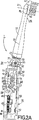
図2Aは、ブラシホルダの一部と、図1に示す歯ブラシのこのブラシホルダによって保持したブラシを示し、ブラシホルダとブラシが通常位置にある状態を示す線図的説明図である。
図2Bは、ブラシホルダの一部と、図1に示す歯ブラシのこのブラシホルダによって保持したブラシを示し、ブラシホルダとブラシが変位位置にある状態を示す図2Aと同様の線図的説明図である。
図1は本発明による歯ブラシ1の関連部分を示す。歯ブラシ1は、歯ブラシ1のグリップ部材を形成する比較的剛強なプラスチックハウジング2を有する。ハウジング2には2個の細条状のサイドグリップを連結し、このうち一方のサイドグリップ3が図1において見ることができる。更に、ハウジング2には弾性プラスチックスイッチカバー4を連結し、このスイッチカバー4をハウジング2に一体にし、このスイッチカバー4の下側に、ハウジング2に収容したプリント回路基板5上の2個スイッチ6,7を配置する。更に、やはりハウジング2に一体にした弾性プラスチック製のドーム状カバー8を設け、このドーム状カバー8には以下に詳細に説明する開口9を設ける。
ハウジング2には第1固定支持体即ちキャリヤ部(固定部)10と第2固定支持体即ちキャリヤ部(固定部)11を収容し、これらのキャリヤ部はともに剛強なプラスチックにより形成する。2個のキャリヤ部10,11は図示しない方法で連結する。2個のキャリヤ部10,11の各々に、それぞれ側面12,13を設ける。プリント回路基板5を2個の側面12,13に取り付ける。2個のキャリヤ部10,11の各々に2個のホルダ部材を設け、第2キャリヤ部11の第1ホルダ部材14及び第2ホルダ部材15のみが図1において見ることができる。第1キャリヤ部10の対応の第1ホルダ部材と関連して第2キャリヤ部11の第1ホルダ部材14が再充電可能バッテリ16のためのホルダ空間を形成し、このバッテリ16はプリント回路基板5上に設けた充電回路を介して充電される。第1キャリヤ部10の対応の第2ホルダ部材に関連して第2キャリヤ部11の第2ホルダ部材15は電動式の駆動モータ17を収容するホルダ空間を形成する。図示しない方法で、駆動モータ17を電気的にプリント回路基板5に接続し、バッテリ16によって電力を供給されるプリント回路基板5上の電源回路によって動作することができる。
駆動モータ17は駆動軸18を有し、図示の実施例ではこの駆動軸18に相対回転不能にロックしたピニオン19を担持する。図1に線図的にのみ示す歯付きホイール20をピニオン19により駆動する。歯付きホイール20は、2個の固定キャリア部10,11に取り付けたスピンドル21によって軸線22の周りに回転自在に取り付ける。軸線22に対して偏心させて配置した中空円筒形の偏心部23を歯付きホイール20に一体にする。
歯ブラシ1には、第1固定キャリヤ部10及び第2固定キャリヤ部11に対して相対移動可能なブラシホルダ24を設ける。このブラシホルダ24は大きな球状をなす球形部25を有し、この球形部25の駆動モータ17に対向する側をほぼ円筒状の円筒形部26に一体に連結し、球形部25の駆動モータ17から遠い方の側をほぼ円筒形の連結部27に一体に連結する。ブラシホルダ24には、更に、球形部25及び円筒形部26に連結したアーム28を設ける。アーム28にはスピンドル21が通過する溝孔29を設ける。アーム28の遊端30にトラニオン31を設け、このトラニオン31をアームに一体にしてアーム28から側方に突出させる。このトラニオン31の目的は以下に説明する。
図1に示す歯ブラシ1において、可動のブラシホルダ24は2個の固定キャリヤ部10,11に対して回動自在に取り付ける。この目的のため、ブラシホルダ24に、2個のトラニオン32を設け、図1には一方のトラニオン32のみを見ることができる。図面に見えている第1トラニオン32は第1キャリヤ部10の第1孔33に掛合する。図面に見えていないトラニオンは第2キャリヤ部11の第2孔34に掛合する。このようにして、ブラシホルダ24は2個の固定キャリヤ部10,11に対して軸線35の周りに回動自在に取り付ける。ブラシホルダ24は、図2Aに示す通常位置と、図2Bに示す変位位置との間で回動自在にする。
ブラシホルダ24はブラシ36を保持する。ブラシ36は、管状部分37及びこの管状部分37のハウジング2から離れる側の端部でこの管状部分37に一体に連結したディスク状部分38を有する。管状部分37及びブラシ36は長手方向軸線39を有する。ブリストル(毛束)ホルダ40をディスク状部分38に移動自在に取り付け、即ち、ブリストルホルダ40が長手方向軸線39に直交するホルダ軸線41の周りに中心位置を通過する2個の変位位置間で往復回動可能にする。
更に、歯間ブリストルホルダ42をディスク状部分38に移動自在に取り付け、即ち、ブラシ36の長手方向軸線39を横切る方向に往復移動可能にし、円弧状経路に沿って往復移動するよう駆動されるブリストルホルダ40に駆動掛合するよう連結し、この結果、歯間ブリストルホルダ42は、ブリストルホルダ40が円弧状経路に沿って追う側方移動するときブラシ36の長手方向軸線39を横切る方向に往復移動するよう駆動される。
ブリストルホルダ40は、上述のピニオン19、歯付きホイール20及び偏心部23を介して駆転モータ17によって駆動される。偏心部23は、ブラシ36の長手方向軸線39に交差するよう突出する連結ロッド44のブロック状突起43に形成した溝孔に掛合する。連結ロッド44は突起43に一体に形成する。連結ロッド44をブラシホルダ24の孔に貫通させ、この孔は円筒形部分26、球形部分25及び円筒形連結部分27を通過する。
ブラシ36をブラシホルダ24に取り付けるとき、管状部分37は図示しないバヨネット連結手段により円筒形連結部分27に機械的に具合よく連結される。更に、連結ロッド44の断面が三角形の遊端45は図示しない駆動ロッドの連結窪みに掛合し、この駆動ロッドは管状部分37内にほぼ長手方向軸線39に沿って移動することができるよう取り付ける。駆動ロッド(図示せず)の連結ロッド44から遠い方の側の端部を回動自在継手を介してブリストルホルダ40に駆動掛合させ、この回動自在継手はホルダ軸線41に対して偏心させて配置する。
ブラシ36の構造に関しては、オーストリア国特許出願第A2112/95号を優先権主張する対応の未公開ヨーロッパ特許出願に記載されていることを参考までに述べる。
歯ブラシ1の組み合わせた条件では、ブラシホルダ24は円筒形連結部分27が弾性プラスチック製のカバー8の開口9から突出し、カバー8の中空円筒形部分46はブラシホルダ24の連結部分27の円筒状溝47に封鎖掛合し、ハウジング内部に湿気又は水が進入するのを排除する。
上述したように、ブラシ36含む歯ブラシ1のブラシホルダ24は図2Aに示す通常位置と図2Bに示す変位位置との間で回動自在にする。歯ブラシ1において、第1キャリヤ部10及びブラシホルダ24との間に作用する螺旋引張ばねによって形成するのが好適なばね48を設ける。ブラシホルダ24は通常位置にばね48のばね力によって保持することができる。作動中にブラシ36に加わる歯磨き力の或る制限値を越えたとき、ブラシ36を含むブラシホルダ24はばね48のばね力に抗して変位位置に移動することができる。
固定キャリヤ部10とブラシホルダ24との間に作用するばね48の他に、歯ブラシ1にはリンク動作装置49を設けると好適である。このリンク動作装置49はこれらの部分間に作用し、ばね48のばね負荷を与えられ、所要の力特性を示すようになる。リンク動作装置49は、摺動面50と、リンク動作追従子(フォロワ)51とを有し、これら摺動面とフォロワは互いに相対移動することができる。更に、リンク動作装置49の摺動面50には、2個の摺動面部分52、53、即ち、第1摺動面部分52及び第2摺動面部分53を設けると好適であり、2個の摺動面部分52,53はエッジ(刃)状移行部分54により互いに隣接させる。
好適な実施例においては、リンク動作装置49には、更に、切り抜き部56を有するスライダ55を設ける。図示の実施例の場合、リンク動作装置49の摺動面50の2個の摺動面部分52,53は、切り抜き部56の2個の境界面部分により形成する。リンク動作装置49のリンク動作フォロワ51を切り抜き部56に掛合させる。リンク動作フォロワ51は、ブラシホルダ24のトラニオン31に回転自在に取り付けたリンク動作ローラ57により構成する。このため、トラニオン31を第1キャリヤ部10に形成した溝孔58に通過させる。このようにして、トラニオン31によりリンク動作フォロワ51はブラシホルダ24の定位置に回転自在に取り付けられる。
スライダ55を第1キャリヤ部10から突出する4個のフック59,60,61,62によって第1固定キャリヤ部10に保持する。このようにして、スライダは第1キャリヤ部10に摺動自在に案内される。スライダ55を摺動自在に案内するため、図示の実施例においては、スライダ55にスライダ55を摺動自在に案内するための単独の溝孔63を設け、この溝孔63は図示の実施例の場合、切り抜き部56に合流させる。溝孔63にはスピンドル21に回転自在に取り付けた案内ローラ64が掛合する。このため、第1キャリヤ部10にはこのスピンドル21を貫通させる。このようにして、案内ローラ64は第1キャリヤ部10の定位置に回転自在に取り付けられる。溝孔63及び案内ローラ64によって、スライダ55は、摺動面50及びリンク動作ローラ57の位置で比較的低摩擦力で案内される。スライダ55は、溝孔63から遠い方のスライダ領域における2個のフック61,62によって長手方向に摺動自在に案内される。しかし、代案として、溝孔に連携動作する案内ローラをこの位置に設けることもできるが、リンク動作ローラ57からの距離が比較的大きいためこの案内ローラを設ける必要は必ずしもない。
歯ブラシ1において、ばね48を第1固定キャリヤ部10とスライダ55との間に配置する。この目的のため、第1固定キャリヤ部10に連結突起65を設け、スライダ55には側方に突出する連結突起66を設ける。ばね48を双方の連結突起65,66に取り付ける。ばね48は、比較的長いばね長さと、高い初期ばね張力と、低い剛さにし、これにより、フラットなばね特性、従って、動作範囲全体にわたりほぼ一定の力を生ずるようにする。
歯ブラシ1の通常の動作中、ブラシ36に加わる歯磨き力が或る限界値(主にリンク動作装置49即ち、ブラシホルダ24が通常位置にあるときリンク動作ローラ57が連携動作する第1摺動面部分52の形状、及びリンク動作装置49の2個の摺動面部分52,53巻のエッジ状移行部分54、並びにばね48のばね力により決定される)以下のとき、ブラシホルダ24及びこのブラシホルダ24が保持するブラシ36は、図2Aに示す通常位置をとり、このとき第1固定キャリヤ部10に連結したばね48はリンク動作装置49のスライダ55に適度な力を発生し、この結果、適度な力がリンク動作ローラ57に第1摺動面部分52を介して加わり、従って、リンク動作ローラ57は摺動面基部分52に当接した状態を維持し、ブラシホルダ24及びこのブラシホルダに担持したブラシ36は通常位置に保持される。
しかし、歯ブラシ1の動作中に上述の限界値を越える歯磨き力がブラシ36に加わると、リンク動作ローラ57はこのような大きな力を第1摺動面部分52に加えて2個の摺動面部分52,53間のエッジ状移行部分54を越えてリンク動作ローラ57を移動し、リンク動作装置49のスライダ55をばね力48に抗して図2Bに矢印67に示す方向に移動し、同時にブラシホルダ24及びこのブラシホルダ24に担持したブラシ36はやはり図2Bに示す矢印68の方向に変位位置に移動する。このようにして、ユーザーは過剰の歯磨き力を加えている状況を知ることができる。
加わった過剰歯磨き力が減少したとき、リンク動作装置49のスライダ55はばね48の力によって図2Bの矢印67で示す方向とは逆方向に図2Aに示す作動位置に移動し、この結果、リンク動作ローラ57は再び第1摺動面部分52に作用を生ずるよう掛合し、ブラシホルダ24及びこのブラシホルダに担持したブラシ36を図2Bの矢印68で示す方向とは逆方向に通常位置に復帰回動させることになる。
所要のばね特性を得るため、上述の歯ブラシに極めて狭い公差範囲内で製造することができるリンク動作装置を設けることによって、ブラシホルダの変位位置への移動がブラシに加わる極めて狭い公差範囲内の歯磨き力で生じすることが簡単な手段及び方法で得られ、このことは好ましくまた有利なことである。
本発明は上述の歯ブラシの実施例に限定されるものではない。例えば、リンクローラによって形成するのが好ましいリンク動作装置のリンク動作フォロワを、第1固定キャリヤ部に回転自在に配置することもでき、この場合、リンク動作装置にはスライダを設け、このスライダを回動自在のブラシホルダに摺動自在に案内し、またスライダに境界面がリンク動作面部分を形成する切り抜き部を設け、このリンク動作装置にばね負荷を与えるばねを回動自在ブラシホルダとスライダとの間に配置し、回動自在ブラシホルダに対してスライダを摺動自在に案内することができる。更に、回動自在ブラシホルダに対して摺動自在に案内し、境界面がリンク動作面部分をなす切り抜き部を設けた他のリンク動作装置を設け、またこの他のリンク動作装置のリンク動作フォロワとして、第1固定キャリヤ部に取り付けたリンク動作ローラをキャリヤ部の長手方向に移動自在かつ回転自在にし、ばねの一方の端部を第1固定キャリヤ部に作用させ、ばねの他方の端部を移動自在に支持したリンク動作ローラに作用させることもできる。The present invention relates to at least one fixing part, a brush holder that can hold a brush and is movable with respect to the fixing part, and acts between the fixing part and the brush holder so that the brush holder can be moved by a spring force. A toothbrush comprising a spring capable of moving the brush holder to a displacement position against the spring force when the toothbrushing force applied to the brush during the operation of the brush exceeds a predetermined limit value It is.
A toothbrush of the type mentioned at the outset is described, for example, in EP-A-0 636 349. In this known toothbrush, the spring arranged between the fixed part and the brush holder is an angled leaf spring, one end of the leaf spring is straightened and fixed to the fixed part, and the other The end portions of the brush holder are bent and engaged with the step pressure surface of the brush holder at the position of the step portion of the brush holder so as to cooperate with each other. In this known toothbrush, the limit value of the brushing force that the brush holder can move to the displacement position against the spring force when the limit value is exceeded is mainly the threshold value of the spring force of the angled leaf spring, the pressure surface , And the frictional condition between the bent end of the leaf spring and the pressure surface of the brush holder. However, the threshold value of the spring force is relatively strongly dependent on the tolerance of the leaf spring, and basically depends on the thickness of the leaf spring, the size of the leaf spring angle, and the shape of the leaf spring, and the bent end of the leaf spring. The frictional conditions between the brush holder and the pressure surface of the brush holder also depend on tolerances and time series aging. Due to this fact, i.e. the influence of relatively strong tolerances, the limit value of the brushing force applied to the brush, which causes the brush holder to move to the displacement position, is greatly widened by the difference in the known toothbrush samples. Is not preferred.
The object of the present invention is therefore to improve a toothbrush of the type mentioned at the outset by solving the above-mentioned problems. In order to achieve this object, in the toothbrush of the present invention, a link operating device is arranged in addition to the spring between the fixed part and the brush holder so as to obtain a required force characteristic, and a spring load by the spring is applied to the link operating device. Furthermore, the link operation device is provided with a link operation surface and a link operation follower (follower), and the link operation surface and the link operation follower (follower) can be moved relative to each other, so that the link operation of the link operation device can be performed. The surface is provided with two link operation surface portions, and the two link operation surface portions are adjacent to each other by an edge-shaped transition portion. In this way, the limit value at which the brush holder can slide to the displacement position against the spring force of the spring when the limit value of the brushing force applied to the brush is exceeded is mainly the link operating device, that is, the basic value. In particular, before the brush holder moves to the displacement position, it is determined by the shape of the sliding surface portion where the link operation follower engages and cooperates and the edge-like transition portion between the two swing surface portions of the link operation device. Since the link operating device can be manufactured within a very narrow tolerance range, in the toothbrush according to the present invention, toothbrush samples with different limit values of the brushing force applied to the brush where the brush holder moves to the displacement position are approximated to each other. This can be done easily, which is preferred and advantageous.
In a preferred embodiment of the toothbrush according to the present invention, the link operation device is constituted by a slidably guided slider having a cutout portion, and two link operation surface portions of the link operation surface of the link operation device are cut out. The link motion follower is engaged with the cutout portion. According to this configuration, there is an advantage that the manufacture and structure of the link operating device is simple and precise, and such a structure can be easily combined.
Further, in a preferred embodiment of the present invention, the slider is slidably guided to the fixed portion, the link operation follower is attached to a fixed position of the brush holder, and the spring is engaged between the fixed portion and the slider. This arrangement is advantageous in that the link operating device can be easily accommodated in a toothbrush having the geometric relationship given to such a toothbrush.
Furthermore, in a preferred embodiment of the present invention, the spring is a helical tension spring. This embodiment is advantageous because such tension springs are available with relatively narrow tolerances.
Furthermore, in another preferred embodiment of the present invention, in order to guide the slider in a slidable manner, at least one slot for engaging the guide roller with the slider is provided. This configuration is advantageous in that the friction condition for guiding the slider is preferable.
Furthermore, it is advantageous if the link operation follower is constituted by a link operation roller rotatably attached. According to this structure, there exists an advantage that a frictional force becomes the minimum in the position where the sliding surface of a link operation | movement apparatus and a link operation follower operate | move mutually.
Embodiments of the present invention will be described below in detail with reference to the drawings, but the present invention is not limited to such embodiments.
FIG. 1 is an exploded perspective view of parts of a
FIG. 2A is a diagrammatic explanatory view showing a part of the brush holder and the brush held by the brush holder of the toothbrush shown in FIG. 1, and showing a state where the brush holder and the brush are in a normal position.
2B is a diagrammatic explanatory view similar to FIG. 2A showing a part of the brush holder and the brush held by the brush holder of the toothbrush shown in FIG. 1 and showing a state where the brush holder and the brush are in the displacement position. is there.
FIG. 1 shows the relevant parts of a
The
The drive motor 17 has a drive shaft 18, and in the illustrated embodiment, carries a pinion 19 that is locked to the drive shaft 18 so as not to be relatively rotatable. A
The
In the
The
Further, an
The
When the
The structure of the
Under the combined condition of the
As described above, the
In addition to the
In a preferred embodiment, the
The
In the
During normal operation of the
However, if a brushing force exceeding the above-mentioned limit value is applied to the
When the applied excessive tooth brushing force is reduced, the
In order to obtain the required spring characteristics, the toothbrushes within the very narrow tolerance range in which the movement of the brush holder to the displacement position is applied to the brush by providing the above-mentioned toothbrush with a link operating device that can be manufactured within a very narrow tolerance range. It can be obtained by simple means and methods that occur with force, which is preferred and advantageous.
The present invention is not limited to the toothbrush embodiment described above. For example, the link operation follower of the link operation device preferably formed by a link roller can be rotatably arranged on the first fixed carrier portion. In this case, the link operation device is provided with a slider, and the slider is rotated. The slider is guided slidably on the movable brush holder, and the slider is provided with a cut-out portion whose boundary surface forms a link operation surface portion. A spring for applying a spring load to the link operation device is provided with the rotatable brush holder and the slider. The slider can be slidably guided with respect to the rotatable brush holder. Further, another link operation device is provided which is slidably guided with respect to the rotatable brush holder and has a cut-out portion whose boundary surface forms a link operation surface portion, and the link operation follower of the other link operation device. The link operation roller attached to the first fixed carrier part is movable and rotatable in the longitudinal direction of the carrier part, one end of the spring is applied to the first fixed carrier part, and the other end of the spring is It is also possible to act on a link operation roller that is movably supported.
Claims (6)
かつ前記固定部に対して移動自在のブラシホルダと、固定部とブラシホルダとの間に作用してばね力によりブラシホルダを通常位置に保持しかつブラシの動作中にブラシに加わる歯磨き力の所定限界値を越えたときばね力に抗してブラシホルダを変位位置に移動することができるばねとを具えた歯ブラシにおいて、所要の力特性を得るよう、固定部とブラシホルダとの間にばねの他にリンク動作装置を配置し、このリンク動作装置にばねによるばね負荷を与え、更に、このリンク動作装置にリンク動作面を設け、このリンク動作面と、前記ブラシホルダに取り付けたリンク動作追従子とを互いに相対移動自在にし、リンク動作装置のリンク動作面には2個のリンク動作面部分を設け、2個のリンク動作面部分をエッジ状移行部分によって互いに隣接させたことを特徴とする歯ブラシ。At least one fixing part, a brush holder capable of holding the brush and movable relative to the fixing part, and acting between the fixing part and the brush holder to bring the brush holder into a normal position by a spring force The required force characteristics of a toothbrush comprising a spring that can move the brush holder to a displaced position against the spring force when a predetermined limit value of the brushing force applied to the brush during the operation of the brush is maintained. In addition to the spring, a link operating device is disposed between the fixed portion and the brush holder, a spring load is applied to the link operating device by a spring, and a link operating surface is provided on the link operating device. link operation surface, wherein the link operation Tsuishoko attached to the brush holder to be relatively movable to each other, the two links operating surface portion or link operating surface of the link operation device provided, Toothbrush is characterized in that is adjacent the number of links operating surface portion by the edge-like transition portion.
Applications Claiming Priority (3)
| Application Number | Priority Date | Filing Date | Title |
|---|---|---|---|
| EP96890193 | 1996-12-17 | ||
| EP96890193.4 | 1996-12-17 | ||
| PCT/IB1997/001343 WO1998026729A1 (en) | 1996-12-17 | 1997-10-27 | Toothbrush having a brush holder movable against spring force |
Publications (3)
| Publication Number | Publication Date |
|---|---|
| JP2000505690A JP2000505690A (en) | 2000-05-16 |
| JP2000505690A5 JP2000505690A5 (en) | 2005-07-14 |
| JP4008039B2 true JP4008039B2 (en) | 2007-11-14 |
Family
ID=8226218
Family Applications (1)
| Application Number | Title | Priority Date | Filing Date |
|---|---|---|---|
| JP52747798A Expired - Lifetime JP4008039B2 (en) | 1996-12-17 | 1997-10-27 | Toothbrush with brush holder that can move against spring force |
Country Status (8)
| Country | Link |
|---|---|
| US (1) | US5901397A (en) |
| EP (1) | EP0888092B1 (en) |
| JP (1) | JP4008039B2 (en) |
| KR (1) | KR19990082564A (en) |
| CN (1) | CN1124829C (en) |
| AT (1) | ATE230957T1 (en) |
| DE (1) | DE69718447T2 (en) |
| WO (1) | WO1998026729A1 (en) |
Families Citing this family (109)
| Publication number | Priority date | Publication date | Assignee | Title |
|---|---|---|---|---|
| DE59707168D1 (en) * | 1997-07-16 | 2002-06-06 | Trisa Buerstenfabrik Ag | Push-on part for a toothbrush powered by a motor, in particular an electric motor |
| US6564940B2 (en) | 1998-09-30 | 2003-05-20 | The Procter & Gamble Company | Electric toothbrush |
| US6178579B1 (en) | 1998-09-30 | 2001-01-30 | Dr. Johns Products, Ltd. | Electric toothbrush |
| USD456998S1 (en) | 1999-01-25 | 2002-05-14 | Lawrence A. Blaustein | Head portion of an electric toothbrush |
| JP2002542579A (en) | 1999-04-14 | 2002-12-10 | コーニンクレッカ フィリップス エレクトロニクス エヌ ヴィ | Device with rechargeable battery |
| EP1132057A1 (en) * | 2000-03-06 | 2001-09-12 | Unilever N.V. | Toothbrush with segmented oscillating head |
| US6920659B2 (en) * | 2001-01-12 | 2005-07-26 | Water Pik, Inc. | Toothbrush |
| US6889829B2 (en) * | 2001-06-29 | 2005-05-10 | Homedics, Inc. | Automatic electric toothbrush in a display package |
| US6895625B2 (en) | 2001-06-29 | 2005-05-24 | Homedics, Inc. | Automatic electric toothbrush |
| US6792640B2 (en) | 2001-06-29 | 2004-09-21 | Homedics, Inc. | Automatic electric toothbrush |
| US6952855B2 (en) * | 2001-06-29 | 2005-10-11 | Homedics, Inc. | Automatic electric toothbrush |
| US20030084526A1 (en) * | 2001-11-06 | 2003-05-08 | The Procter & Gamble Co. | Multi-motion toothbrush |
| US6725490B2 (en) | 2001-11-06 | 2004-04-27 | The Procter & Gamble Company | Complex motion toothbrush |
| US20030084525A1 (en) * | 2001-11-07 | 2003-05-08 | The Procter & Gamble Company | Complex motion toothbrush |
| KR100677660B1 (en) * | 2001-11-06 | 2007-02-02 | 더 프록터 앤드 갬블 캄파니 | Multi-motion toothbrush |
| US20030084527A1 (en) * | 2001-11-06 | 2003-05-08 | The Procter & Gamble Co. | Multi-motion toothbrush |
| USD499884S1 (en) | 2002-03-15 | 2004-12-21 | The Procter & Gamble Company | Electric toothbrush |
| US20030140437A1 (en) * | 2002-01-31 | 2003-07-31 | Eyal Eliav | Powered toothbrush |
| US6931688B2 (en) * | 2002-08-09 | 2005-08-23 | Colgate-Palmolive Company | Toothbrush |
| US7055531B2 (en) * | 2004-07-07 | 2006-06-06 | Rehco, Llc | Electronic oral cleaning device |
| US20040134001A1 (en) * | 2002-09-13 | 2004-07-15 | The Procter & Gamble Company | Toothbrushes with a replaceable head having a threaded connection |
| US6948209B2 (en) * | 2002-09-13 | 2005-09-27 | The Procter & Gamble Company | Electric toothbrushes having flexible necks |
| US20040107521A1 (en) * | 2002-12-06 | 2004-06-10 | The Procter & Gamble Company | Electric toothbrushes |
| US7147468B2 (en) | 2002-12-31 | 2006-12-12 | Water Pik, Inc. | Hand held oral irrigator |
| US7434286B2 (en) * | 2003-02-26 | 2008-10-14 | Colgate-Palmolive Company | Powered toothbrush with improved ergonomics |
| US20040177458A1 (en) | 2003-03-10 | 2004-09-16 | The Procter & Gamble Company | Electric toothbrushes |
| CN100579486C (en) * | 2003-07-16 | 2010-01-13 | 丘奇&德怀特有限公司 | Electric toothbrushes having movable, intermittently movable, and fixed bristles |
| US7383603B2 (en) * | 2003-11-25 | 2008-06-10 | Fitmouth, Inc. | Flexible neck toothbrush |
| US7694419B2 (en) | 2005-04-27 | 2010-04-13 | The Gillette Company | Battery-operated appliances |
| US7845041B2 (en) * | 2005-05-03 | 2010-12-07 | Colgate-Palmolive Company | Interactive musical toothbrush |
| US8225449B2 (en) * | 2005-05-03 | 2012-07-24 | Colgate-Palmolive Company | Interactive toothbrush |
| US20070203439A1 (en) | 2006-02-24 | 2007-08-30 | Water Pik, Inc. | Water jet unit and handle |
| WO2007101210A2 (en) * | 2006-02-27 | 2007-09-07 | Water Pik, Inc. | Tip for oral irrigator |
| US7670141B2 (en) | 2006-07-07 | 2010-03-02 | Water Pik, Inc. | Oral irrigator |
| USD802120S1 (en) | 2007-02-27 | 2017-11-07 | Water Pik, Inc. | Tip for oral irrigator |
| US8544132B2 (en) * | 2008-05-07 | 2013-10-01 | John Gatzemeyer | Interactive toothbrush and removable audio output module |
| US20100186234A1 (en) | 2009-01-28 | 2010-07-29 | Yehuda Binder | Electric shaver with imaging capability |
| US20100190132A1 (en) | 2009-01-28 | 2010-07-29 | Water Pik, Inc. | Oral irrigator tip |
| US10258442B2 (en) | 2009-03-20 | 2019-04-16 | Water Pik, Inc. | Oral irrigator appliance with radiant energy delivery for bactericidal effect |
| US9061096B2 (en) | 2009-12-16 | 2015-06-23 | Water Pik, Inc. | Powered irrigator for sinus cavity rinse |
| USD670373S1 (en) | 2010-12-16 | 2012-11-06 | Water Pik, Inc. | Powered irrigator for sinus cavity rinse |
| CA2834911C (en) | 2011-05-02 | 2017-01-17 | Water Pik, Inc. | Mechanically-driven, sonic toothbrush |
| USD707350S1 (en) | 2012-10-11 | 2014-06-17 | Water Pik, Inc. | Handheld water flosser |
| US10105201B2 (en) | 2012-10-11 | 2018-10-23 | Water Pik, Inc. | Interdental cleaner using water supply |
| USD725770S1 (en) | 2013-03-14 | 2015-03-31 | Water Pik, Inc. | Reservoir for water flosser |
| USD788907S1 (en) | 2013-03-14 | 2017-06-06 | Water Pik, Inc. | Water flosser base unit with reservoir lid |
| USD717427S1 (en) | 2013-03-14 | 2014-11-11 | Water Pik, Inc. | Handle for water flosser |
| US9642677B2 (en) | 2013-03-14 | 2017-05-09 | Water Pik, Inc. | Oral irrigator with massage mode |
| USD714929S1 (en) | 2013-03-14 | 2014-10-07 | Water Pik, Inc. | Base for water flosser |
| KR102425192B1 (en) | 2013-03-15 | 2022-07-28 | 워터 피크 인코포레이티드 | Mechanically driven, sonic toothbrush and water flosser |
| US9468511B2 (en) * | 2013-03-15 | 2016-10-18 | Water Pik, Inc. | Electronic toothbrush with vibration dampening |
| CN103494434B (en) * | 2013-09-26 | 2015-06-03 | 中国科学院深圳先进技术研究院 | Force limited toothbrush |
| US9980793B2 (en) | 2013-11-27 | 2018-05-29 | Water Pik, Inc. | Oral hygiene system |
| CN107714220B (en) | 2013-11-27 | 2020-12-22 | 洁碧有限公司 | Oral irrigator with sliding pause switch |
| CN203693808U (en) | 2013-12-12 | 2014-07-09 | 洁碧有限公司 | Dental water sprayer |
| CN205586102U (en) | 2014-12-01 | 2016-09-21 | 洁碧有限公司 | Waterproof wireless oral cavity flusher |
| USD772396S1 (en) | 2014-12-01 | 2016-11-22 | Water Pik, Inc. | Handheld oral irrigator |
| USD772397S1 (en) | 2014-12-01 | 2016-11-22 | Water Pik, Inc. | Oral irrigator with a charging device |
| CN205568226U (en) | 2015-07-08 | 2016-09-14 | 洁碧有限公司 | Device of brushing teeth |
| USD780908S1 (en) | 2015-11-03 | 2017-03-07 | Water Pik, Inc. | Handheld oral irrigator |
| USD822196S1 (en) | 2016-01-14 | 2018-07-03 | Water Pik, Inc. | Oral irrigator |
| USD796028S1 (en) | 2016-07-19 | 2017-08-29 | Water Pik, Inc. | Oral irrigator |
| USD794773S1 (en) | 2016-07-19 | 2017-08-15 | Water Pik, Inc. | Oral irrigator |
| USD802747S1 (en) | 2016-07-19 | 2017-11-14 | Water Pik, Inc. | Reservoir for oral irrigator |
| USD786422S1 (en) | 2016-01-25 | 2017-05-09 | Water Pik, Inc. | Oral irrigator |
| US10835356B2 (en) | 2016-01-25 | 2020-11-17 | Water Pik, Inc. | Swivel assembly for oral irrigator handle |
| USD804018S1 (en) | 2016-07-19 | 2017-11-28 | Water Pik, Inc. | Base for an oral irrigator |
| US11213376B2 (en) | 2016-01-25 | 2022-01-04 | Water Pik, Inc. | Reduced form factor oral irrigator |
| USD819956S1 (en) | 2016-01-25 | 2018-06-12 | Water Pik, Inc. | Kit bag |
| USD782656S1 (en) | 2016-01-25 | 2017-03-28 | Water Pik, Inc. | Oral irrigator |
| USD783809S1 (en) | 2016-01-25 | 2017-04-11 | Water Pik, Inc. | Oral irrigator handle |
| USD804016S1 (en) | 2016-02-05 | 2017-11-28 | Water Pik, Inc. | Handheld oral irrigator |
| USD783810S1 (en) | 2016-02-22 | 2017-04-11 | Water Pik, Inc. | Handle for an oral irrigator |
| USD809650S1 (en) | 2016-02-22 | 2018-02-06 | Water Pik, Inc. | Oral irrigator |
| CN109069242B (en) | 2016-03-02 | 2021-02-26 | 洁碧有限公司 | Actuation assembly for oral irrigator |
| USD802119S1 (en) | 2016-03-02 | 2017-11-07 | Water Pik, Inc. | Oral irrigator |
| USD782657S1 (en) | 2016-03-02 | 2017-03-28 | Water Pik, Inc. | Oral irrigator handle |
| US10561480B2 (en) | 2016-05-09 | 2020-02-18 | Water Pik, Inc. | Load sensing for oral devices |
| USD807822S1 (en) | 2016-07-19 | 2018-01-16 | Water Pik, Inc. | Power supply cartridge |
| USD809651S1 (en) | 2016-07-19 | 2018-02-06 | Water Pik, Inc. | Combination base and reservoir for an oral irrigator |
| USD822825S1 (en) | 2016-12-15 | 2018-07-10 | Water Pik, Inc. | Oral irrigator unit |
| USD867579S1 (en) | 2016-12-15 | 2019-11-19 | Water Pik, Inc. | Oral irrigator unit |
| USD840023S1 (en) | 2016-12-15 | 2019-02-05 | Water Pik, Inc. | Oral irrigator reservoir |
| USD845636S1 (en) | 2016-12-15 | 2019-04-16 | Water Pik, Inc. | Toothbrush handle |
| USD832419S1 (en) | 2016-12-15 | 2018-10-30 | Water Pik, Inc. | Oral irrigator unit |
| USD834180S1 (en) | 2016-12-15 | 2018-11-20 | Water Pik, Inc. | Oral irrigator base |
| USD825741S1 (en) | 2016-12-15 | 2018-08-14 | Water Pik, Inc. | Oral irrigator handle |
| USD829886S1 (en) | 2016-12-15 | 2018-10-02 | Water Pik, Inc. | Oral irrigator base |
| USD822826S1 (en) | 2016-12-15 | 2018-07-10 | Water Pik, Inc. | Oral irrigator base |
| WO2018112416A1 (en) | 2016-12-15 | 2018-06-21 | Water Pik, Inc. | Pause valve and swivel assemblies for oral irrigator handle |
| USD833000S1 (en) | 2016-12-15 | 2018-11-06 | Water Pik, Inc. | Oral irrigator unit |
| USD832420S1 (en) | 2016-12-15 | 2018-10-30 | Water Pik, Inc. | Oral irrigator base |
| USD832418S1 (en) | 2016-12-15 | 2018-10-30 | Water Pik, Inc. | Oral irrigator base |
| USD833600S1 (en) | 2016-12-15 | 2018-11-13 | Water Pik, Inc. | Oral irrigator reservoir |
| US11389279B2 (en) | 2016-12-15 | 2022-07-19 | Water Pik, Inc. | Oral irrigator with magnetic attachment |
| USD839409S1 (en) | 2016-12-15 | 2019-01-29 | Water Pik, Inc. | Oral irrigator unit |
| CN110267622B (en) | 2016-12-15 | 2021-08-13 | 洁碧有限公司 | Scrubbing apparatus with illuminated features |
| USD840022S1 (en) | 2016-12-15 | 2019-02-05 | Water Pik, Inc. | Oral irrigator handle |
| USD844997S1 (en) | 2016-12-15 | 2019-04-09 | Water Pik, Inc. | Toothbrush handle |
| USD833602S1 (en) | 2017-02-06 | 2018-11-13 | Water Pik, Inc. | Oral irrigator base |
| USD829887S1 (en) | 2017-02-06 | 2018-10-02 | Water Pik, Inc. | Oral irrigator reservoir |
| USD833601S1 (en) | 2017-02-06 | 2018-11-13 | Water Pik, Inc. | Oral irrigator |
| USD868243S1 (en) | 2018-03-16 | 2019-11-26 | Water Pik, Inc. | Oral irrigator tip |
| USD877324S1 (en) | 2018-05-17 | 2020-03-03 | Water Pik, Inc. | Oral irrigator handle |
| USD888936S1 (en) | 2019-02-22 | 2020-06-30 | Water Pik, Inc. | Cordless water flosser |
| USD889636S1 (en) | 2019-02-22 | 2020-07-07 | Water Pik, Inc. | Water flosser |
| USD966498S1 (en) | 2020-09-15 | 2022-10-11 | Water Pik, Inc. | Oral irrigator |
| USD1016274S1 (en) | 2021-02-16 | 2024-02-27 | Water Pik, Inc. | Oral irrigator |
| CN113180365A (en) * | 2021-05-26 | 2021-07-30 | 上海携福电器有限公司 | Tooth brush |
Family Cites Families (2)
| Publication number | Priority date | Publication date | Assignee | Title |
|---|---|---|---|---|
| US5253382A (en) * | 1992-08-31 | 1993-10-19 | Janos Beny | Power operated toothbrush |
| BE1007432A3 (en) * | 1993-07-30 | 1995-06-13 | Philips Electronics Nv | Toothbrush |
-
1997
- 1997-10-27 JP JP52747798A patent/JP4008039B2/en not_active Expired - Lifetime
- 1997-10-27 AT AT97945036T patent/ATE230957T1/en not_active IP Right Cessation
- 1997-10-27 WO PCT/IB1997/001343 patent/WO1998026729A1/en not_active Application Discontinuation
- 1997-10-27 CN CN97192308A patent/CN1124829C/en not_active Expired - Lifetime
- 1997-10-27 EP EP97945036A patent/EP0888092B1/en not_active Expired - Lifetime
- 1997-10-27 DE DE69718447T patent/DE69718447T2/en not_active Expired - Lifetime
- 1997-10-27 KR KR1019980706302A patent/KR19990082564A/en not_active Application Discontinuation
- 1997-12-11 US US08/988,599 patent/US5901397A/en not_active Expired - Lifetime
Also Published As
| Publication number | Publication date |
|---|---|
| CN1124829C (en) | 2003-10-22 |
| CN1211172A (en) | 1999-03-17 |
| WO1998026729A1 (en) | 1998-06-25 |
| US5901397A (en) | 1999-05-11 |
| ATE230957T1 (en) | 2003-02-15 |
| KR19990082564A (en) | 1999-11-25 |
| EP0888092B1 (en) | 2003-01-15 |
| EP0888092A1 (en) | 1999-01-07 |
| JP2000505690A (en) | 2000-05-16 |
| DE69718447D1 (en) | 2003-02-20 |
| DE69718447T2 (en) | 2003-10-23 |
Similar Documents
| Publication | Publication Date | Title |
|---|---|---|
| JP4008039B2 (en) | Toothbrush with brush holder that can move against spring force | |
| US6237178B1 (en) | Toothbrush comprising a brush member having bristles of different lengths, and brush member having bristles of different lengths for a tooth brush | |
| KR100915732B1 (en) | Hair clipper | |
| US3379906A (en) | Electric appliance with selective motion conversion means | |
| EP0914234B1 (en) | Hair-cutting apparatus having a toothed cutting device, and toothed cutting device for a hair-cutting apparatus | |
| US5701673A (en) | Dry shaving apparatus with pivotally mounted long-hair trimmer | |
| US4167060A (en) | Electric shaver | |
| JPH07222397A (en) | Converter for converting rotational motion into reciprocating motion | |
| JP2008522759A (en) | electric toothbrush | |
| US7698822B2 (en) | Personal care apparatus with an automatically pivotable head part | |
| JPH11508809A (en) | Haircut device having a toothed cutter device and toothed cutting device used for such a haircut device | |
| NL9002400A (en) | ELECTRIC RAZOR. | |
| EP0468622A2 (en) | Variable resistance switch | |
| IT1238322B (en) | TAPPETS IN PARTICULAR FOR COOPERATION WITH CAMSHAFTS IN ELECTRIC SWITCHES, SWITCHES OR SIMILAR | |
| MX9102109A (en) | ELECTRIC SHAVING MACHINE WITH FLEXIBLE BLADE HOLDER | |
| US5555973A (en) | Slide switch device | |
| CA1074592A (en) | Appliance driven by an electric motor | |
| ATE201287T1 (en) | BRUSH HOLDER FOR AN ELECTRIC MOTOR | |
| KR102172998B1 (en) | Apparatus for opening and closing door of vehicle | |
| EP0757366A2 (en) | Electrical roller contactor | |
| JPS6328817Y2 (en) | ||
| SU653633A1 (en) | Push-button switch | |
| JP2594619B2 (en) | Light switch | |
| SU1231543A1 (en) | Slide arm selector switch | |
| JPS591658Y2 (en) | electric razor |
Legal Events
| Date | Code | Title | Description |
|---|---|---|---|
| A521 | Request for written amendment filed |
Free format text: JAPANESE INTERMEDIATE CODE: A523 Effective date: 20041026 |
|
| A621 | Written request for application examination |
Free format text: JAPANESE INTERMEDIATE CODE: A621 Effective date: 20041026 |
|
| A131 | Notification of reasons for refusal |
Free format text: JAPANESE INTERMEDIATE CODE: A131 Effective date: 20070306 |
|
| A521 | Request for written amendment filed |
Free format text: JAPANESE INTERMEDIATE CODE: A523 Effective date: 20070606 |
|
| RD02 | Notification of acceptance of power of attorney |
Free format text: JAPANESE INTERMEDIATE CODE: A7422 Effective date: 20070606 |
|
| TRDD | Decision of grant or rejection written | ||
| RD02 | Notification of acceptance of power of attorney |
Free format text: JAPANESE INTERMEDIATE CODE: A7422 Effective date: 20070703 |
|
| A01 | Written decision to grant a patent or to grant a registration (utility model) |
Free format text: JAPANESE INTERMEDIATE CODE: A01 Effective date: 20070731 |
|
| A61 | First payment of annual fees (during grant procedure) |
Free format text: JAPANESE INTERMEDIATE CODE: A61 Effective date: 20070829 |
|
| FPAY | Renewal fee payment (event date is renewal date of database) |
Free format text: PAYMENT UNTIL: 20100907 Year of fee payment: 3 |
|
| R150 | Certificate of patent or registration of utility model |
Free format text: JAPANESE INTERMEDIATE CODE: R150 |
|
| FPAY | Renewal fee payment (event date is renewal date of database) |
Free format text: PAYMENT UNTIL: 20110907 Year of fee payment: 4 |
|
| FPAY | Renewal fee payment (event date is renewal date of database) |
Free format text: PAYMENT UNTIL: 20120907 Year of fee payment: 5 |
|
| FPAY | Renewal fee payment (event date is renewal date of database) |
Free format text: PAYMENT UNTIL: 20120907 Year of fee payment: 5 |
|
| FPAY | Renewal fee payment (event date is renewal date of database) |
Free format text: PAYMENT UNTIL: 20130907 Year of fee payment: 6 |
|
| R250 | Receipt of annual fees |
Free format text: JAPANESE INTERMEDIATE CODE: R250 |
|
| R250 | Receipt of annual fees |
Free format text: JAPANESE INTERMEDIATE CODE: R250 |
|
| R250 | Receipt of annual fees |
Free format text: JAPANESE INTERMEDIATE CODE: R250 |
|
| R250 | Receipt of annual fees |
Free format text: JAPANESE INTERMEDIATE CODE: R250 |
|
| R250 | Receipt of annual fees |
Free format text: JAPANESE INTERMEDIATE CODE: R250 |
|
| EXPY | Cancellation because of completion of term |