JP4006941B2 - Vehicle power generation control device - Google Patents
Vehicle power generation control device Download PDFInfo
- Publication number
- JP4006941B2 JP4006941B2 JP2000336395A JP2000336395A JP4006941B2 JP 4006941 B2 JP4006941 B2 JP 4006941B2 JP 2000336395 A JP2000336395 A JP 2000336395A JP 2000336395 A JP2000336395 A JP 2000336395A JP 4006941 B2 JP4006941 B2 JP 4006941B2
- Authority
- JP
- Japan
- Prior art keywords
- voltage
- vehicle
- power supply
- power generation
- circuit
- Prior art date
- Legal status (The legal status is an assumption and is not a legal conclusion. Google has not performed a legal analysis and makes no representation as to the accuracy of the status listed.)
- Expired - Fee Related
Links
- 238000010248 power generation Methods 0.000 title claims description 42
- 238000004804 winding Methods 0.000 claims description 45
- 230000000630 rising effect Effects 0.000 claims description 7
- 230000005284 excitation Effects 0.000 claims description 4
- 238000001514 detection method Methods 0.000 description 18
- 238000010586 diagram Methods 0.000 description 10
- 230000005415 magnetization Effects 0.000 description 5
- 230000007423 decrease Effects 0.000 description 4
- 230000004907 flux Effects 0.000 description 4
- 238000010438 heat treatment Methods 0.000 description 3
- 238000000034 method Methods 0.000 description 3
- 239000007858 starting material Substances 0.000 description 2
- 238000000137 annealing Methods 0.000 description 1
- 239000003990 capacitor Substances 0.000 description 1
- 230000003247 decreasing effect Effects 0.000 description 1
- 230000006866 deterioration Effects 0.000 description 1
- 238000011835 investigation Methods 0.000 description 1
- 238000004519 manufacturing process Methods 0.000 description 1
- 230000003134 recirculating effect Effects 0.000 description 1
- 238000005728 strengthening Methods 0.000 description 1
- 230000007704 transition Effects 0.000 description 1
Images


Classifications
-
- H—ELECTRICITY
- H02—GENERATION; CONVERSION OR DISTRIBUTION OF ELECTRIC POWER
- H02P—CONTROL OR REGULATION OF ELECTRIC MOTORS, ELECTRIC GENERATORS OR DYNAMO-ELECTRIC CONVERTERS; CONTROLLING TRANSFORMERS, REACTORS OR CHOKE COILS
- H02P9/00—Arrangements for controlling electric generators for the purpose of obtaining a desired output
- H02P9/14—Arrangements for controlling electric generators for the purpose of obtaining a desired output by variation of field
- H02P9/26—Arrangements for controlling electric generators for the purpose of obtaining a desired output by variation of field using discharge tubes or semiconductor devices
- H02P9/30—Arrangements for controlling electric generators for the purpose of obtaining a desired output by variation of field using discharge tubes or semiconductor devices using semiconductor devices
- H02P9/305—Arrangements for controlling electric generators for the purpose of obtaining a desired output by variation of field using discharge tubes or semiconductor devices using semiconductor devices controlling voltage
-
- H—ELECTRICITY
- H02—GENERATION; CONVERSION OR DISTRIBUTION OF ELECTRIC POWER
- H02J—CIRCUIT ARRANGEMENTS OR SYSTEMS FOR SUPPLYING OR DISTRIBUTING ELECTRIC POWER; SYSTEMS FOR STORING ELECTRIC ENERGY
- H02J7/00—Circuit arrangements for charging or depolarising batteries or for supplying loads from batteries
- H02J7/14—Circuit arrangements for charging or depolarising batteries or for supplying loads from batteries for charging batteries from dynamo-electric generators driven at varying speed, e.g. on vehicle
- H02J7/1446—Circuit arrangements for charging or depolarising batteries or for supplying loads from batteries for charging batteries from dynamo-electric generators driven at varying speed, e.g. on vehicle in response to parameters of a vehicle
-
- H—ELECTRICITY
- H02—GENERATION; CONVERSION OR DISTRIBUTION OF ELECTRIC POWER
- H02P—CONTROL OR REGULATION OF ELECTRIC MOTORS, ELECTRIC GENERATORS OR DYNAMO-ELECTRIC CONVERTERS; CONTROLLING TRANSFORMERS, REACTORS OR CHOKE COILS
- H02P9/00—Arrangements for controlling electric generators for the purpose of obtaining a desired output
- H02P9/08—Control of generator circuit during starting or stopping of driving means, e.g. for initiating excitation
-
- Y—GENERAL TAGGING OF NEW TECHNOLOGICAL DEVELOPMENTS; GENERAL TAGGING OF CROSS-SECTIONAL TECHNOLOGIES SPANNING OVER SEVERAL SECTIONS OF THE IPC; TECHNICAL SUBJECTS COVERED BY FORMER USPC CROSS-REFERENCE ART COLLECTIONS [XRACs] AND DIGESTS
- Y02—TECHNOLOGIES OR APPLICATIONS FOR MITIGATION OR ADAPTATION AGAINST CLIMATE CHANGE
- Y02T—CLIMATE CHANGE MITIGATION TECHNOLOGIES RELATED TO TRANSPORTATION
- Y02T10/00—Road transport of goods or passengers
- Y02T10/80—Technologies aiming to reduce greenhouse gasses emissions common to all road transportation technologies
- Y02T10/92—Energy efficient charging or discharging systems for batteries, ultracapacitors, supercapacitors or double-layer capacitors specially adapted for vehicles
Description
【0001】
【発明の属する技術分野】
本発明は、乗用車やトラック等に搭載される車両用発電機の発電状態を制御する車両用発電制御装置に関する。
【0002】
【従来の技術】
一般の車両用交流発電機は、固定子鉄心に固定子巻線を巻装した固定子と、界磁極に界磁巻線を巻装した回転子とを有しており、界磁巻線に界磁電流を流した状態で回転子を回転させたときに固定子巻線に誘起される交流電圧を整流して出力電圧として取り出す構造になっている。ところが、界磁巻線に界磁電流を通電しない状態で回転子を回転させても、固定子巻線に微少な交流電圧が現れる。これは、回転子の界磁極には残留磁束が存在するためである。
【0003】
このような微少な交流電圧を利用する従来技術として、実開昭62−44698号公報に開示された「制御回路」が知られている。この制御回路は、界磁極に残留する磁化に起因した固定子巻線の誘起電圧の周波数を検出することにより回転子が回転を開始したか否か、すなわち車両に搭載されたエンジンが起動されたか否かを検出しており、エンジンの起動を検出したときに界磁巻線に対して界磁電流の導通を開始する。このように、固定子巻線の誘起電圧に基づいてエンジンが起動されたことを検出することにより、車両側からイグニッションスイッチの断続状態を知らせるために用いられている信号線を廃止することができるため、配線の簡略化が可能となる。
【0004】
【発明が解決しようとする課題】
しかしながら、発明者等による調査によれば、エンジンの始動時と停止時では、界磁極に現れる残留磁化の状態や回転状態の挙動に著しい差異があることがわかった。このため、従来の回路では、回転開始状態と回転停止状態を検出する周波数を同一に設定すると、エンジンの回転状態の検出を充分な精度で行うことができないという問題があった。
【0005】
一般に、エンジン始動時に固定子巻線に現れる電圧信号は、界磁極に残留した磁束のみに起因するものなので極めて小さい。周知の通り、固定子巻線に鎖交する磁束の大きさが一定の場合に、固定子巻線に誘起される電圧の振幅と周波数は、回転子の回転数に比例する。この周波数を検出するには、固定子巻線に現れた電圧信号を電圧比較器等を用いて二値化した後、所定のデジタル処理を行うことになる。残留磁化に起因する微少な信号で回転数検出を行うためには、上述した電圧比較器の比較基準電圧を小さな値に設定する必要があるが、小さすぎるとノイズ等の外来信号に反応して誤検出のおそれがある。このため、電圧比較器の比較基準電圧は、外来ノイズに反応しない程度に大きく設定する必要がある。しかし、一方では、電圧比較器の比較基準電圧を大きくすると、固定子巻線の誘起電圧が大きくならないと二値化されたパルスを生成することができないため、検出可能な回転数が高くなってしまう。
【0006】
エンジンの始動時にはスタータによって始動後にエンジンが完爆した後、一旦所定回転数まで回転数が上昇した後にアイドリング回転数に到達するので、回転数を検出する周波数を比較的高く設定してもエンジンの始動状態を検出することができる。特に、周囲温度が低い冬の時期には、初期アイドリング回転数をそれ以外の時期よりも高く設定して、暖気を促進するような制御が実施されるため、より高回転で運転が開始される。
【0007】
しかしながら、始動検出回転数を通常のアイドリング設定回転数相当以上に設定すると、例えば信号待ち等のアイドリング時に発電を維持できないという事態を招くおそれもある。
【0008】
このような不都合を回避するためには、発電開始回転数を低くするために、固定子巻線の巻数を多くすればよいが、高回転域での出力電流が低下してしまうため、車載バッテリの充放電収支を悪化させることになり、良好な解決策であるとはいえない。
【0009】
また、特開平6−292329号公報に開示された出力制御装置のように、回転数に応じて巻線を切り替える方法も考えられるが、回路規模が大きくなってしまうため、現実的な解決策とはいえない。例えば、車両用交流発電機の体格を大型化することができれば回路規模の拡大に対処することは可能であるが、最近の省スペース化や低騒音、低コスト化の要求に応えるためには、体格の大型化は採用しにくい手法であり、実現は難しい。
【0010】
また、米国特許第5,429,687号公報に開示された交流発電機のように、界磁極に熱処理を施して磁気特性を改善し、残留磁束が増すような結晶状態に遷移させる磁気焼鈍等の手法も一般には知られているが、熱容量が大きな界磁極に対して熱処理を行うために、規模が大きな熱処理装置を導入する必要があり、製造コストの観点から採用は難しい。
【0011】
本発明は、このような点に鑑みて創作されたものであり、その目的は、回路規模の増大や充放電収支の悪化を招くことなく、エンジンの回転検出の精度を向上させることができる車両用発電制御装置を提供することにある。
【0012】
【課題を解決するための手段】
上述した課題を解決するために、本発明の車両用発電制御装置は、電圧制御手段、電源手段、電源制御手段を備えている。電圧制御手段は、車両用発電機の界磁巻線に直列接続された第1のスイッチング手段を断続させることにより、車両用発電機の出力電圧を制御する。電源手段は、電圧制御回路の動作電圧を生成する。電源制御手段は、車両用発電機の固定子巻線の相電圧の周波数が第1の基準周波数を超えた場合に電源手段による動作電圧の生成動作を開始させるとともに、相電圧の周波数がこの第1の基準周波数よりも小さな第2の基準周波数を下回ったときに電源手段による動作電圧の生成動作を停止させる制御を行う。
【0013】
エンジン始動時の検出を第1の基準周波数に対応する高い回転数で行うことができるため、ノイズ等による誤検出を防止することができ、検出精度を向上させることができる。また、巻線の切り替え等が不要であるため回路規模の増大を招くこともなく、固定子巻線の巻数を増やす必要もないため充放電収支の悪化を招くこともない。
【0014】
一般に、車両用発電機の界磁巻線の時定数は数百msec程度なので、エンジン停止時にキースイッチ(イグニッションスイッチ)を切ってからエンジンが完全に停止するまでの時間よりも、車両用発電機の回転子の低下を検出して界磁電流を停止するまでの時間の方が長い。したがって、本発明によれば、エンジン稼働中に車両用発電機による電力供給が停止することなく車両用発電機の発電状態を制御することができ、しかもキースイッチの断続状態を車両用発電制御装置に通知するために必要であった信号線を廃止することができる。
【0015】
また、上述した第1の基準周波数は、車両用発電機の全励磁状態における立ち上がり回転数の2倍以下の回転数であり、第2の基準周波数は立ち上がり回転数以下であることが望ましい。エンジン始動後は、車両用発電機の立ち上がり回転数以下の低い回転数を基準にしてエンジンの停止状態が判断されるため、エンジンのアイドリング時に誤ってエンジンの停止を検出することを防止することができ、エンジン稼働中は確実にバッテリやその他の電気負荷に対して電力を供給することができる。
【0016】
また、上述した相電圧を検出する端子と車載用バッテリの負極電位側との間に挿入された第2のスイッチング手段と、この相電圧が基準電圧を超えたときに、所定期間だけ第2のスイッチング手段をオン状態に制御するスイッチング制御手段とをさらに備えることが望ましい。これにより、バッテリから固定子巻線等に流れるリーク電流によって生じる直流ドリフト電圧に起因する誤検出を防止することができる。また、通常の発電状態においてこの第2のスイッチング手段をオン状態にしておくと損失となるため、このオン状態の期間を所定期間とすることで、発電時における損失を抑えることができる。
【0017】
また、上述したスイッチング制御手段によって第2のスイッチング手段がオン状態に制御されるタイミングに合わせて、界磁巻線に界磁電流を流す界磁電流供給手段をさらに備えることが望ましい。相電圧を検出する端子に流れ込むリーク電流が大きい場合には、上述した第2のスイッチング手段をオン状態にしても、リーク電流による直流ドリフト電圧を十分に打ち消すことができない場合がある。このような場合には、界磁巻線に界磁電流を流すことにより界磁極の磁化を強化することにより固定子巻線に誘起される相電圧を増大させることができる。したがって、相電圧を検出するために用いられる比較電圧をある程度高く設定することができ、リーク電流に影響されずに確実にエンジンの回転検出を行うことができる。
【0018】
【発明の実施の形態】
以下、本発明を適用した一実施形態の車両用発電制御装置について、図面を参照しながら詳細に説明する。
【0019】
〔第1の実施形態〕
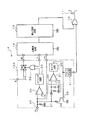
図1は、本発明を適用した第1の実施形態の車両用発電制御装置の構成を示す図であり、あわせてこの車両用発電制御装置と車両用発電機やバッテリとの接続状態が示されている。
【0020】
図1において、車両用発電制御装置1は、車両用発電機2の出力電圧を所定範囲内に制御する。車両用発電機2は、固定子に含まれる3相の固定子巻線21と、回転子に含まれる界磁巻線22と、固定子巻線21の3相出力を全波整流する全波整流回路23とを含んで構成されている。この車両用発電機2の出力電圧の制御は、界磁巻線22に通電する界磁電流を調整することにより行われる。車両用発電機2の出力端子(B端子)はバッテリ3やその他の電気負荷(図示せず)に接続されており、車両用発電機2からこれらに対して電流が供給される。
【0021】
次に、車両用発電制御装置1の詳細構成について説明する。図1に示すように、車両用発電制御装置1は、界磁巻線22に直列に接続されて界磁電流を断続する第1のスイッチング手段としてのパワートランジスタ11と、界磁コイル22に並列に接続されてパワートランジスタ11がオフ状態のときに界磁電流を還流させる還流ダイオード12と、車両用発電機2の出力電圧を監視してこの出力電圧が所定範囲内に収まるようにパワートランジスタ11の断続状態を制御する電圧制御回路13と、この電圧制御回路13の動作状態を維持するために電力を供給する主電源回路14と、固定子巻線21のいずれかの相電圧(例えばY相電圧Py)に基づいて車両用発電機2の回転子が回転したこと、すなわちエンジンが回転したことを検出して主電源回路14を駆動する副電源回路15とを含んで構成されている。
【0022】
図2は、主電源回路14および副電源回路15の詳細構成を示す回路図である。
【0023】
副電源回路15は、図2に示すように、電圧比較器30、31、カウンタ回路32、オア回路33、アナログスイッチ34、ピーク検出回路35、タイマ回路36、抵抗37、38、トランジスタ39を含んで構成されている。電圧比較器30は、入力端子40に印加されるY相電圧Pyを所定の基準電圧V1と比較して二値化することにより、車両用発電機2の回転数に応じたパルス信号を生成する。カウンタ回路32は、電圧比較器30から出力されるパルス信号の数をカウントし、このカウント数が所定値N1に達したときに出力の論理を反転させる。
【0024】
トランジスタ39は、固定子巻線21あるいは全波整流回路23に発生するリーク電流をアースに流し込むための第2のスイッチング手段であり、例えばMOS型のFETで構成される。抵抗38は、入力端子40とトランジスタ39の間に接続されており、入力端子40とアースとの間に接続された抵抗37よりも低い抵抗値が設定されている。
【0025】
ピーク検出回路35は、入力端子40に印加されるY相電圧Pyの波高値を検出するためのものであり、ダイオード、コンデンサおよび抵抗からなっている。電圧比較器31は、ピーク検出回路35によって検出されたY相電圧Pyの波高値を所定の基準電圧V2と比較することにより、この波高値が所定の基準電圧V2を超えたか否かを判定する。この基準電圧V2は、上述した電圧比較器30に印加される基準電圧V1よりも低い値に設定されている。タイマ回路36は、Y相電圧Pyの波高値が基準電圧V2を超えたときに所定時間だけ動作する。このタイマ回路36から出力される信号がトランジスタ39のゲートに入力されており、タイマ回路36が動作している期間だけ、トランジスタ39がオン状態に制御されて、入力端子40に流れ込むリーク電流をアースに導く。
【0026】
アナログスイッチ34は、主電源回路14に動作電圧IGを印加するためものであり、OR回路33の出力論理に応じてオンオフ動作が制御される。OR回路33は、カウンタ回路32の出力信号と主電源回路14から入力される所定の信号(後述する)とが入力されており、これら2つの入力信号の論理和出力をアナログスイッチ34の制御端子に入力する。
【0027】
また、主電源回路14は、図2に示すように、電圧比較器50、カウンタ回路51、直流電源回路52を含んで構成されている。電圧比較器50は、Y相電圧Pyを所定の基準電圧V3と比較して二値化することにより、車両用発電機2の回転数に応じたパルス信号を出力する。例えば、この基準電圧V3は、副電源回路15内の電圧比較器30に印加されている基準電圧V1と同じ値に設定されている。タイマ回路51は、電圧比較器50から出力されるパルス信号の数をカウントし、このカウント数が所定値N2に達したときに出力の論理を反転する。この所定値N2は、副電源回路15内のカウンタ回路32で用いられる所定値N1よりも小さな値に設定されている。直流電源回路52は、電圧制御回路13の動作電圧を生成するものであり、副電源回路15内のアナログスイッチ34を介して印加されるB端子電圧を平滑化する。また、直流電源回路52は、車両用発電機2が発電中は、B端子からバッテリ3に印加される車両用発電機2の出力電圧に含まれる整流リップルや転流ノイズ等を除去する働きをする。
【0028】
上述した電圧制御回路13が電圧制御手段に、主電源回路14が電源手段に、副電源回路15が電源制御手段にそれぞれ対応する。
【0029】
本実施形態の車両用発電制御装置1はこのような構成を有しており、次にその動作を説明する。図3は、車両用発電制御装置1によって制御される車両用発電機2の発電状態を示す図である。
【0030】
スタータが回されてエンジンが始動され、車両用発電機2が回転を開始すると、副電源回路15の入力端子40に印加されるY相電圧Pyの振幅が次第に大きくなる。このY相電圧Pyの振幅が電圧比較器30のマイナス端子に印加された基準電圧V1よりも大きくなると、電圧比較器30からは、車両用発電機2の回転数に比例した周波数を有する所定のパルス信号が生成されて、カウンタ回路32に入力される。このようにしてカウンタ回路32に入力される所定時間内のパルス数が所定値N1を超えると、すなわち、車両用発電機2の回転数が所定値N1に相当する回転数fsに達すると、カウンタ回路32の出力がローレベルからハイレベルに変化するため、アナログスイッチ34がオン状態になり、車両用発電機2のB端子を介してバッテリ3から印加される電圧が主電源回路14内の直流電源回路52に供給されて、電圧制御回路13による車両用発電機2の出力電圧の制御動作が開始される。
【0031】
ところで、車両用発電機2が回転を開始していない状態でも、固定子巻線21や全波整流回路23にリーク電流が発生すると直流ドリフト電圧が生じるため、副電源回路15の入力端子40に現れる電圧が上昇する。ピーク検出回路35は、入力端子40に現れる電圧を検出しており、この検出電圧が所定の基準電圧V2を超えると電圧比較器31の出力がローレベルからハイレベルに変化するため、タイマ回路36が起動されてトランジスタ39が所定期間オン状態になる。したがって、副電源回路15の入力端子40が抵抗38を介して接地され、リーク電流によってこの入力端子40に現れる直流ドリフト電圧が抑制されるため、再び入力端子40の電圧が低下してほぼアース電位に等しい電位に安定する。このため、入力端子40に現れる電圧が、電圧比較器30に印加されている基準電圧V1を超えることはなく、アナログスイッチ34のオフ状態が維持される。なお、実際に車両用発電機2の回転数が上昇して入力端子40に現れる電圧が上昇した場合には、トランジスタ39が所定期間オン状態になっても、この入力端子40に現れる電圧は上昇を続けるため、上述したように車両用発電機2の回転数が所定値fsに達したときにアナログスイッチ34がオン状態になる。
【0032】
実際に車両用発電機2が回転を開始してアナログスイッチ34がオン状態になると、主電源回路14内の直流電源回路52が動作を開始するため、この直流電源回路52から電圧比較器50およびカウンタ回路51に動作電圧が供給され、これらの動作が開始する。カウンタ回路51において出力論理を反転させる基準となる所定値N2は、回転開始時にアナログスイッチ34をオフ状態からオン状態に変化させるために動作する副電源回路15内のカウンタ回路32に設定された所定値N1よりも小さな値に設定されているため、車両用発電機2の回転数がこの所定値N2に相当する低い回転数fe以上を維持する限り、カウンタ回路51の出力はハイレベルを維持し、アナログスイッチ34のオン状態が維持される。
【0033】
すなわち、エンジン始動検出時には、主電源回路14内の直流電源回路42は動作していないため、カウンタ回路51も動作しておらず、副電源回路15内のカウンタ回路32の設定値N1に相当する回転数fsに達した時点で主電源回路14が動作を開始する。
【0034】
一方、エンジン停止時には、この設定値N1に相当する回転数fsを下回った時点では、まだカウンタ回路51の出力がハイレベルに維持されているため主電源回路14の動作が継続している。したがって、設定値N1に相当する回転数fsよりも車両用発電機2の回転数が下回っても主電源回路14が動作を継続しており、バッテリ3やその他の電気負荷への電力供給が遮断されることはない。この状態では、電圧制御回路13によってパワートランジスタ11が制御されて励磁巻線22に界磁電流が供給されるため、実在磁化に起因する誘導電圧が固定子巻線23のY相に発生しており、電圧比較器30によって容易に二値化してパルス信号を生成することができる。
【0035】
さらに車両用発電機2の回転数が低くなって、カウンタ回路51の設定値N2に相当する回転数feを下回ると、カウンタ回路51の出力がハイレベルからローレベルに変化するため、アナログスイッチ34の制御端子に入力される信号がローレベルになり、アナログスイッチ34がオフ状態になる。これにより、主電源回路14が動作を停止するため、励磁巻線22に対する界磁電流の通電が中止され、バッテリ3やその他の電気負荷に対する電力供給が停止する。
【0036】
このように、本実施形態の車両用発電制御装置1では、エンジン始動時の検出を高い回転数fsで行うことができるため、ノイズ等による誤検出を防止することができ、検出精度を向上させることができる。特に、巻線の切り替え等が不要であるため回路規模の増大を招くこともなく、固定子巻線の巻数を増やす必要もないため充放電収支の悪化を招くこともない。
【0037】
また、一般には、車両用発電機2の界磁巻線22の時定数は数百msec程度なので、エンジン停止時にキースイッチを切ってからエンジンが完全に停止するまでの時間よりも、車両用発電機2の回転子の低下を検出して界磁電流を停止するまでの時間の方が長い。したがって、エンジン稼働中に車両用発電機2による電力供給が停止することなく車両用発電機2の発電状態を制御することができ、しかもキースイッチの断続状態を車両用発電制御装置に通知するために必要であって信号線を廃止することができる。
【0038】
特に、上述したエンジン始動状態の検出を行う回転数fsを車両用発電機2の全励磁状態における立ち上がり回転数の2倍以下程度に設定するとともに、エンジン停止状態の検出を行う回転数feを車両用発電機2の立ち上がり回転数以下に設定することが望ましい。このような設定を行うことにより、エンジンの始動状態のノイズによる誤検出を防止するとともに、エンジンのアイドリング時に誤ってエンジンの停止を検出することを防止することができ、エンジン稼働中は確実にバッテリやその他の電気負荷に対して電力を供給することができる。
【0039】
〔第2の実施形態〕
図4は、本発明を適用した第2の実施形態の車両用発電制御装置の構成を示す図である。図4に示した車両用発電制御装置1Aは、図1に示した車両用発電制御装置1に対して、副電源回路15を副電源回路15Aに置き換えるとともに、パワートランジスタ11の前段(ゲート側)にオア回路16を追加した点が異なっている。この副電源回路15Aは、図2に示した副電源回路15に対して、タイマ回路36の出力側にパルス発生器41を追加した点が異なっている。
【0040】
パルス発生器41は、タイマ回路36が動作してトランジスタ39がオン状態に制御されるタイミングで、所定周期のパルス信号を生成する。このパルス信号は、オア回路16を介してパワートランジスタ11のゲートに入力されている。このパルス発生器41が界磁電流供給手段に対応する。したがって、副電源回路15Aの入力端子40の電圧が上昇して基準電圧V2に達したときに、パルス発生器41によって生成されるパルス信号によってパワートランジスタ11を断続的にオン状態に制御することにより、励磁巻線22に一時的に界磁電流を流している。これにより、固定子巻線21のY相に誘起される電圧を増幅することができ、エンジンの始動検出を容易かつ確実にしている。
【0041】
〔第3の実施形態〕
図5は、本発明を適用した第3の実施形態の車両用発電制御装置の構成を示す図である。図5に示した車両用発電制御装置1Bは、図1に示した車両用発電制御装置1に対して、副電源回路15を副電源回路15Bに置き換えるとともに、主電源回路14を主電源回路14Bに置き換えた点が異なっている。この副電源回路15Bは、図2に示した副電源回路15に対して、カウンタ回路32とオア回路33を変換器42と電圧比較器43に置き換えた点が異なっている。
【0042】
変換器42は、入力されるパルス信号の周波数を電圧に変換する。したがって、車両用発電機2の回転数が高くなるにしたがって変換器42の出力電圧が上昇し、反対に車両用発電機2の回転数が低くなるにしたがって変換器42の出力電圧が低下する。電圧比較器43は、ヒステリシスを有しており、変換器42の出力電圧が上昇しているときにはこの出力電圧が第1の基準電圧Vf1以上になると出力をローレベルからハイレベルに切り替える。また、変換器42の出力電圧が低下しているときには、電圧比較器43は、第1の基準電圧Vf1よりも低い第2の基準電圧Vf2に達したときに、出力をハイレベルからローレベルに切り替える。これにより、エンジンの始動検出時には比較的高い回転数が設定され、車両用発電機2の回転数がこの高い設定回転数よりも上回ったときに、車両用発電制御装置1Bによる界磁電流の供給動作が開始される。一方、エンジンの停止検出時にはこれより低い回転数が設定され、車両用発電機2の回転数がこの低い設定回転数を下回ったときに、車両用発電制御装置1Bによる界磁電流の供給動作が停止される。
【0043】
また、このようにして副電源回路15B内の電圧比較器43による電圧比較動作にヒステリシスを持たせることにより、主電源回路14B内には電圧比較器50やカウンタ回路51を備える必要がなく、回路構成の簡略化が可能になる。
【図面の簡単な説明】
【図1】第1の実施形態の車両用発電制御装置の構成を示す図である。
【図2】主電源回路および副電源回路の詳細構成を示す回路図である。
【図3】車両用発電制御装置によって制御される車両用発電機の発電状態を示す図である。
【図4】第2の実施形態の車両用発電制御装置の構成を示す図である。
【図5】第3の実施形態の車両用発電制御装置の構成を示す図である。
【符号の説明】
1 車両用発電制御装置
2 車両用発電機
3 バッテリ
11 パワートランジスタ
12 還流ダイオード
13 電圧制御回路
14 主電源回路
15 副電源回路
21 固定子巻線
22 界磁巻線
23 全波整流回路[0001]
BACKGROUND OF THE INVENTION
The present invention relates to a vehicle power generation control device that controls a power generation state of a vehicle generator mounted on a passenger car, a truck, or the like.
[0002]
[Prior art]
A general vehicle AC generator has a stator in which a stator winding is wound around a stator core, and a rotor in which a field winding is wound around a field pole. When the rotor is rotated with a field current flowing, the AC voltage induced in the stator winding is rectified and output as an output voltage. However, even if the rotor is rotated without applying a field current to the field winding, a minute AC voltage appears in the stator winding. This is because residual magnetic flux exists at the field pole of the rotor.
[0003]
A “control circuit” disclosed in Japanese Utility Model Laid-Open No. 62-44698 is known as a prior art using such a minute AC voltage. This control circuit detects whether the rotor has started rotating by detecting the frequency of the induced voltage in the stator winding caused by the magnetization remaining in the field pole, that is, whether the engine mounted on the vehicle has been started. When the start of the engine is detected, the conduction of the field current to the field winding is started. Thus, by detecting that the engine is started based on the induced voltage of the stator winding, it is possible to eliminate the signal line used for notifying the intermittent state of the ignition switch from the vehicle side. Therefore, the wiring can be simplified.
[0004]
[Problems to be solved by the invention]
However, according to the investigation by the inventors, it has been found that there is a significant difference in the behavior of the residual magnetization and the rotating state appearing in the field pole when the engine is started and when it is stopped. For this reason, in the conventional circuit, if the frequency for detecting the rotation start state and the rotation stop state are set to be the same, there is a problem that the rotation state of the engine cannot be detected with sufficient accuracy.
[0005]
In general, the voltage signal that appears in the stator windings when the engine is started is very small because it is caused only by the magnetic flux remaining in the field pole. As is well known, when the magnitude of the magnetic flux linked to the stator winding is constant, the amplitude and frequency of the voltage induced in the stator winding are proportional to the number of rotations of the rotor. In order to detect this frequency, the voltage signal appearing on the stator winding is binarized using a voltage comparator or the like, and then predetermined digital processing is performed. In order to detect the rotational speed with a minute signal due to residual magnetization, it is necessary to set the comparison reference voltage of the voltage comparator described above to a small value, but if it is too small, it reacts to external signals such as noise. There is a risk of false detection. For this reason, the comparison reference voltage of the voltage comparator needs to be set large enough not to react to external noise. However, on the other hand, if the comparison reference voltage of the voltage comparator is increased, a binarized pulse cannot be generated unless the induced voltage of the stator winding is increased. End up.
[0006]
When starting the engine, after the engine is completely exploded after being started by the starter, it reaches the idling rotational speed after the rotational speed has once increased to a predetermined rotational speed. Therefore, even if the frequency for detecting the rotational speed is set relatively high, A starting condition can be detected. In particular, in winter when the ambient temperature is low, the initial idling speed is set higher than in other periods and control is performed to promote warm-up, so operation starts at a higher speed. .
[0007]
However, if the start detection rotation speed is set to be equal to or higher than the normal idling setting rotation speed, there is a possibility that power generation cannot be maintained during idling such as waiting for a signal.
[0008]
In order to avoid such an inconvenience, the number of turns of the stator winding may be increased in order to reduce the power generation start rotation speed. However, since the output current in the high rotation range is reduced, the vehicle-mounted battery This will worsen the charge / discharge balance and is not a good solution.
[0009]
Also, a method of switching the windings according to the number of rotations as in the output control device disclosed in Japanese Patent Laid-Open No. 6-292329 is conceivable, but since the circuit scale becomes large, I can't say that. For example, if the size of the vehicle alternator can be increased, it is possible to cope with the expansion of the circuit scale, but in order to meet the recent demands for space saving, low noise, and low cost, Enlarging the physique is a technique that is difficult to adopt and difficult to implement.
[0010]
Moreover, like the AC generator disclosed in US Pat. No. 5,429,687, magnetic annealing is performed to improve the magnetic characteristics by subjecting the field poles to heat treatment, and transition to a crystalline state in which residual magnetic flux increases. Although this method is also generally known, in order to perform heat treatment on a field pole having a large heat capacity, it is necessary to introduce a heat treatment apparatus having a large scale, which is difficult to adopt from the viewpoint of manufacturing cost.
[0011]
The present invention was created in view of the above points, and an object of the present invention is to improve the accuracy of engine rotation detection without causing an increase in circuit scale or deterioration in charge / discharge balance. It is to provide a power generation control device.
[0012]
[Means for Solving the Problems]
In order to solve the above-described problems, the vehicle power generation control device of the present invention includes voltage control means, power supply means, and power supply control means. The voltage control means controls the output voltage of the vehicle generator by intermittently connecting the first switching means connected in series to the field winding of the vehicle generator. The power supply means generates an operating voltage for the voltage control circuit. The power supply control means starts the operation of generating the operating voltage by the power supply means when the frequency of the phase voltage of the stator winding of the vehicle generator exceeds the first reference frequency, and the frequency of the phase voltage is Control is performed to stop the operation of generating the operating voltage by the power supply means when the frequency falls below a second reference frequency smaller than the reference frequency of 1.
[0013]
Since detection at the time of engine start can be performed at a high rotational speed corresponding to the first reference frequency, erroneous detection due to noise or the like can be prevented, and detection accuracy can be improved. Further, since there is no need to switch the windings, the circuit scale is not increased, and the number of turns of the stator windings is not increased, so that the charge / discharge balance is not deteriorated.
[0014]
In general, the time constant of the field winding of a vehicular generator is about several hundreds of milliseconds, so the vehicular generator is longer than the time from when the key switch (ignition switch) is turned off when the engine is stopped until the engine is completely stopped. It takes longer to detect the decrease of the rotor and stop the field current. Therefore, according to the present invention, the power generation state of the vehicular generator can be controlled without stopping the power supply by the vehicular generator during engine operation, and the intermittent state of the key switch is controlled by the vehicular power generation control device. It is possible to abolish the signal line that was necessary for notification.
[0015]
In addition, it is desirable that the first reference frequency described above is a rotation speed not more than twice the rising rotation speed in the full excitation state of the vehicle generator, and the second reference frequency is not more than the rising rotation speed. After the engine is started, the engine stop state is determined based on a low rotation speed equal to or lower than the rising rotation speed of the vehicular generator. Therefore, it is possible to prevent erroneous detection of the engine stop when the engine is idling. It is possible to reliably supply power to the battery and other electric loads while the engine is running.
[0016]
The second switching means inserted between the terminal for detecting the phase voltage described above and the negative electrode potential side of the vehicle-mounted battery, and when the phase voltage exceeds the reference voltage, It is desirable to further include switching control means for controlling the switching means to be in an ON state. Thereby, it is possible to prevent erroneous detection due to a DC drift voltage caused by a leakage current flowing from the battery to the stator winding or the like. Further, since the loss occurs when the second switching means is turned on in the normal power generation state, the loss during power generation can be suppressed by setting the on-state period to a predetermined period.
[0017]
In addition, it is desirable to further include field current supply means for supplying a field current to the field winding in accordance with the timing at which the second switching means is controlled to be turned on by the switching control means described above. When the leak current flowing into the terminal for detecting the phase voltage is large, the DC drift voltage due to the leak current may not be sufficiently canceled even if the second switching means described above is turned on. In such a case, the phase voltage induced in the stator winding can be increased by strengthening the magnetization of the field pole by flowing a field current through the field winding. Therefore, the comparison voltage used for detecting the phase voltage can be set to be high to some extent, and the engine rotation can be reliably detected without being affected by the leakage current.
[0018]
DETAILED DESCRIPTION OF THE INVENTION
Hereinafter, a vehicle power generation control apparatus according to an embodiment to which the present invention is applied will be described in detail with reference to the drawings.
[0019]
[First Embodiment]
FIG. 1 is a diagram showing a configuration of a vehicle power generation control device according to a first embodiment to which the present invention is applied, and also shows a connection state between the vehicle power generation control device and a vehicle power generator or battery. ing.
[0020]
In FIG. 1, the vehicle power
[0021]
Next, a detailed configuration of the vehicle power
[0022]
FIG. 2 is a circuit diagram showing a detailed configuration of the main
[0023]
As shown in FIG. 2, the sub
[0024]
The
[0025]
The
[0026]
The
[0027]
Further, as shown in FIG. 2, the main
[0028]
The
[0029]
The vehicle power
[0030]
When the starter is turned to start the engine and the vehicular generator 2 starts to rotate, the amplitude of the Y-phase voltage Py applied to the
[0031]
By the way, even when the vehicle generator 2 has not started to rotate, if a leakage current is generated in the stator winding 21 or the full-
[0032]
When the vehicular generator 2 actually starts rotating and the
[0033]
That is, when the engine start is detected, since the DC
[0034]
On the other hand, when the engine is stopped, the operation of the main
[0035]
Further, when the rotational speed of the vehicular generator 2 becomes lower and falls below the rotational speed fe corresponding to the set value N2 of the
[0036]
As described above, in the vehicle power
[0037]
In general, the time constant of the field winding 22 of the vehicular generator 2 is about several hundred msec, so that the vehicular power generation is shorter than the time from when the key switch is turned off when the engine is stopped until the engine is completely stopped. It takes longer to detect the decrease in the rotor of the machine 2 and stop the field current. Therefore, it is possible to control the power generation state of the vehicle generator 2 without stopping the power supply by the vehicle generator 2 while the engine is operating, and to notify the vehicle power generation control device of the on / off state of the key switch. The signal line can be abolished.
[0038]
In particular, the rotational speed fs for detecting the engine start state described above is set to about twice or less the rising rotational speed in the full excitation state of the vehicle generator 2, and the rotational speed fe for detecting the engine stop state is set to the vehicle. It is desirable to set it below the rising rotation speed of the power generator 2. By making such settings, it is possible to prevent erroneous detection due to engine start-up noise, and to prevent erroneous detection of engine stop when the engine is idling. Power can be supplied to and other electrical loads.
[0039]
[Second Embodiment]
FIG. 4 is a diagram showing a configuration of a vehicle power generation control device according to a second embodiment to which the present invention is applied. A vehicle power generation control device 1A shown in FIG. 4 replaces the sub
[0040]
The
[0041]
[Third Embodiment]
FIG. 5 is a diagram showing a configuration of a vehicle power generation control device according to a third embodiment to which the present invention is applied. The vehicle power generation control device 1B shown in FIG. 5 replaces the sub
[0042]
The
[0043]
Further, by providing hysteresis to the voltage comparison operation by the
[Brief description of the drawings]
FIG. 1 is a diagram illustrating a configuration of a vehicle power generation control device according to a first embodiment.
FIG. 2 is a circuit diagram showing a detailed configuration of a main power supply circuit and a sub power supply circuit.
FIG. 3 is a diagram showing a power generation state of a vehicle generator controlled by a vehicle power generation control device.
FIG. 4 is a diagram illustrating a configuration of a vehicle power generation control device according to a second embodiment.
FIG. 5 is a diagram illustrating a configuration of a vehicle power generation control device according to a third embodiment;
[Explanation of symbols]
DESCRIPTION OF
Claims (4)
前記電圧制御回路の動作電圧を生成する電源手段と、
前記車両用発電機の固定子巻線の相電圧の周波数が第1の基準周波数を超えた場合に前記電源手段による前記動作電圧の生成動作を開始させるとともに、前記相電圧の周波数がこの第1の基準周波数よりも小さな第2の基準周波数を下回ったときに前記電源手段による前記動作電圧の生成動作を停止させる制御を行う電源制御手段と、
を備えることを特徴とする車両用発電制御装置。Voltage control means for controlling the output voltage of the vehicle generator by intermittently connecting the first switching means connected in series to the field winding of the vehicle generator;
Power supply means for generating an operating voltage of the voltage control circuit;
When the frequency of the phase voltage of the stator winding of the vehicle generator exceeds the first reference frequency, the operation of generating the operating voltage by the power supply means is started, and the frequency of the phase voltage is the first frequency. Power control means for performing control to stop the operation of generating the operating voltage by the power supply means when the frequency falls below a second reference frequency smaller than the reference frequency of
A vehicle power generation control device comprising:
前記第1の基準周波数は、前記車両用発電機の全励磁状態における立ち上がり回転数の2倍以下の回転数であり、前記第2の基準周波数は前記立ち上がり回転数以下であることを特徴とする車両用発電制御装置。In claim 1,
The first reference frequency is a rotation speed that is not more than twice a rising rotation speed in a full excitation state of the vehicle generator, and the second reference frequency is not more than the rising rotation speed. Vehicle power generation control device.
前記相電圧を検出する端子と車載用バッテリの負極電位側との間に挿入された第2のスイッチング手段と、
前記相電圧が基準電圧を超えたときに、所定期間だけ前記第2のスイッチング手段をオン状態に制御するスイッチング制御手段と、
をさらに備えることを特徴とする車両用発電制御装置。In claim 1 or 2,
A second switching means inserted between the terminal for detecting the phase voltage and the negative potential side of the vehicle battery;
Switching control means for controlling the second switching means to be in an on state only for a predetermined period when the phase voltage exceeds a reference voltage;
A vehicle power generation control device further comprising:
前記スイッチング制御手段によって前記第2のスイッチング手段がオン状態に制御されるタイミングに合わせて、前記界磁巻線に界磁電流を流す界磁電流供給手段をさらに備えることを特徴とする車両用発電制御装置。In claim 3,
The vehicle power generation further comprising field current supply means for causing a field current to flow through the field winding in accordance with a timing at which the second switching means is controlled to be turned on by the switching control means. Control device.
Priority Applications (4)
| Application Number | Priority Date | Filing Date | Title |
|---|---|---|---|
| JP2000336395A JP4006941B2 (en) | 2000-11-02 | 2000-11-02 | Vehicle power generation control device |
| US09/978,537 US6603289B2 (en) | 2000-11-02 | 2001-10-18 | Vehicle alternator control device and method |
| DE60115815T DE60115815T2 (en) | 2000-11-02 | 2001-10-24 | Vehicle alternator control device and method |
| EP01125245A EP1204200B1 (en) | 2000-11-02 | 2001-10-24 | Vehicle alternator control device and method |
Applications Claiming Priority (1)
| Application Number | Priority Date | Filing Date | Title |
|---|---|---|---|
| JP2000336395A JP4006941B2 (en) | 2000-11-02 | 2000-11-02 | Vehicle power generation control device |
Publications (2)
| Publication Number | Publication Date |
|---|---|
| JP2002142497A JP2002142497A (en) | 2002-05-17 |
| JP4006941B2 true JP4006941B2 (en) | 2007-11-14 |
Family
ID=18811976
Family Applications (1)
| Application Number | Title | Priority Date | Filing Date |
|---|---|---|---|
| JP2000336395A Expired - Fee Related JP4006941B2 (en) | 2000-11-02 | 2000-11-02 | Vehicle power generation control device |
Country Status (4)
| Country | Link |
|---|---|
| US (1) | US6603289B2 (en) |
| EP (1) | EP1204200B1 (en) |
| JP (1) | JP4006941B2 (en) |
| DE (1) | DE60115815T2 (en) |
Cited By (1)
| Publication number | Priority date | Publication date | Assignee | Title |
|---|---|---|---|---|
| JP2012105496A (en) * | 2010-11-12 | 2012-05-31 | Denso Corp | Vehicle power generation control device |
Families Citing this family (8)
| Publication number | Priority date | Publication date | Assignee | Title |
|---|---|---|---|---|
| JP4006941B2 (en) * | 2000-11-02 | 2007-11-14 | 株式会社デンソー | Vehicle power generation control device |
| JP3982247B2 (en) * | 2001-12-06 | 2007-09-26 | 株式会社デンソー | Control device for vehicle generator |
| JP2006501793A (en) * | 2002-07-31 | 2006-01-12 | シドクラフト、アクチボラグ | Electric machine |
| US7605569B2 (en) | 2007-01-31 | 2009-10-20 | Infineon Technologies Ag | Acquisition circuit and controller circuit for an alternator |
| JP5445185B2 (en) | 2010-02-05 | 2014-03-19 | 株式会社デンソー | Vehicle generator |
| EP2578218A1 (en) | 2011-10-06 | 2013-04-10 | Grindeks, A Joint Stock Company | Antiviral efficacy of disodium 2,6-dimethyl-1,4-dihydropyridine-3,5-bis(carbonyloxyacetate) and its derivatives |
| JP6477600B2 (en) | 2016-05-30 | 2019-03-06 | 株式会社デンソー | Restart control system |
| TWI620408B (en) * | 2016-12-21 | 2018-04-01 | 朋程科技股份有限公司 | Regulator, and vehicle alternator and rotating speed detection method thereof |
Family Cites Families (14)
| Publication number | Priority date | Publication date | Assignee | Title |
|---|---|---|---|---|
| US4384245A (en) * | 1980-08-12 | 1983-05-17 | Trw Inc. | Alternator voltage regulator |
| JPS6244698U (en) | 1985-09-09 | 1987-03-18 | ||
| JP2576233B2 (en) * | 1989-07-13 | 1997-01-29 | 三菱電機株式会社 | Control device for vehicle alternator |
| US5266836A (en) * | 1992-06-30 | 1993-11-30 | Ford Motor Company | Method and apparatus for operating a motor vehicle alternator |
| JPH06335298A (en) * | 1993-03-23 | 1994-12-02 | Mitsubishi Electric Corp | Method and apparatus for controlling output of alternator for vehicle |
| JPH06284598A (en) * | 1993-03-29 | 1994-10-07 | Sawafuji Electric Co Ltd | Charger/discharger for vehicle |
| JPH06292329A (en) | 1993-04-05 | 1994-10-18 | Mitsubishi Electric Corp | Alternator output controller for vehicle |
| US5429687A (en) | 1994-01-03 | 1995-07-04 | Ateliers Thome-Genot | Process for manufacturing alternator pole piece |
| JP3897832B2 (en) * | 1995-06-23 | 2007-03-28 | 株式会社デンソー | Vehicle power supply |
| US6215285B1 (en) * | 1999-10-20 | 2001-04-10 | Delphi Technologies, Inc. | Apparatus and method for providing an output signal indicative of engine rotational speed and/or generator rotational speed |
| JP3509007B2 (en) * | 2000-06-29 | 2004-03-22 | 株式会社デンソー | AC generator for vehicles |
| JP3519048B2 (en) * | 2000-10-18 | 2004-04-12 | 三菱電機株式会社 | Voltage control device for vehicle alternator |
| JP4006941B2 (en) * | 2000-11-02 | 2007-11-14 | 株式会社デンソー | Vehicle power generation control device |
| US6483198B2 (en) * | 2001-01-19 | 2002-11-19 | Transportation Techniques Llc | Hybrid electric vehicle having a selective zero emission mode, and method of selectively operating the zero emission mode |
-
2000
- 2000-11-02 JP JP2000336395A patent/JP4006941B2/en not_active Expired - Fee Related
-
2001
- 2001-10-18 US US09/978,537 patent/US6603289B2/en not_active Expired - Fee Related
- 2001-10-24 DE DE60115815T patent/DE60115815T2/en not_active Expired - Lifetime
- 2001-10-24 EP EP01125245A patent/EP1204200B1/en not_active Expired - Lifetime
Cited By (2)
| Publication number | Priority date | Publication date | Assignee | Title |
|---|---|---|---|---|
| JP2012105496A (en) * | 2010-11-12 | 2012-05-31 | Denso Corp | Vehicle power generation control device |
| US8723486B2 (en) | 2010-11-12 | 2014-05-13 | Denso Corporation | Device for controlling power generation of on-vehicle power generator |
Also Published As
| Publication number | Publication date |
|---|---|
| EP1204200B1 (en) | 2005-12-14 |
| EP1204200A3 (en) | 2003-07-30 |
| DE60115815D1 (en) | 2006-01-19 |
| US6603289B2 (en) | 2003-08-05 |
| EP1204200A2 (en) | 2002-05-08 |
| US20020050810A1 (en) | 2002-05-02 |
| JP2002142497A (en) | 2002-05-17 |
| DE60115815T2 (en) | 2006-09-14 |
Similar Documents
| Publication | Publication Date | Title |
|---|---|---|
| JP4622758B2 (en) | Voltage control device for vehicle | |
| JP3664379B2 (en) | Voltage control device for vehicle alternator | |
| KR100737955B1 (en) | Method and apparatus for controlling power generation using gradually exciting technique | |
| US6603277B2 (en) | Apparatus for controlling cooling fan for vehicle | |
| JPH08126223A (en) | Controller for a.c. generator | |
| JP4438261B2 (en) | Vehicle alternator | |
| JP4229013B2 (en) | AC generator | |
| JP4006941B2 (en) | Vehicle power generation control device | |
| JP4186432B2 (en) | Voltage control device for vehicle alternator | |
| JP4193348B2 (en) | Vehicle power generation control device | |
| JP4200672B2 (en) | Vehicle power generation control device | |
| JP4192427B2 (en) | Vehicle power generation control device | |
| US6750634B2 (en) | Vehicular power generation control device and method | |
| JP3015098B2 (en) | Alternator | |
| JPH06351285A (en) | Drive controller for brushless motor | |
| JP3629881B2 (en) | Power generation stop detection method for vehicle alternator | |
| JP4006614B2 (en) | AC generator for vehicles | |
| JP2002171687A (en) | Commutator of charging generator for vehicle | |
| JP3629880B2 (en) | Power generation stop detection method for vehicle alternator | |
| JP4135052B2 (en) | AC generator for vehicles | |
| JP4232071B2 (en) | Control device for vehicle alternator | |
| CN108702112B (en) | Method and control device for multiphase synchronous rotating electrical machine with excitation and corresponding vehicle generator-starter | |
| JP3362424B2 (en) | Voltage control device for vehicle alternator | |
| JP4482786B2 (en) | Voltage control device for vehicle alternator | |
| JP2004080853A (en) | Power generation controller for vehicle |
Legal Events
| Date | Code | Title | Description |
|---|---|---|---|
| A621 | Written request for application examination |
Free format text: JAPANESE INTERMEDIATE CODE: A621 Effective date: 20060626 |
|
| A977 | Report on retrieval |
Free format text: JAPANESE INTERMEDIATE CODE: A971007 Effective date: 20070725 |
|
| TRDD | Decision of grant or rejection written | ||
| A01 | Written decision to grant a patent or to grant a registration (utility model) |
Free format text: JAPANESE INTERMEDIATE CODE: A01 Effective date: 20070807 |
|
| A61 | First payment of annual fees (during grant procedure) |
Free format text: JAPANESE INTERMEDIATE CODE: A61 Effective date: 20070820 |
|
| FPAY | Renewal fee payment (event date is renewal date of database) |
Free format text: PAYMENT UNTIL: 20100907 Year of fee payment: 3 |
|
| R150 | Certificate of patent or registration of utility model |
Free format text: JAPANESE INTERMEDIATE CODE: R150 |
|
| FPAY | Renewal fee payment (event date is renewal date of database) |
Free format text: PAYMENT UNTIL: 20100907 Year of fee payment: 3 |
|
| FPAY | Renewal fee payment (event date is renewal date of database) |
Free format text: PAYMENT UNTIL: 20110907 Year of fee payment: 4 |
|
| FPAY | Renewal fee payment (event date is renewal date of database) |
Free format text: PAYMENT UNTIL: 20110907 Year of fee payment: 4 |
|
| FPAY | Renewal fee payment (event date is renewal date of database) |
Free format text: PAYMENT UNTIL: 20120907 Year of fee payment: 5 |
|
| FPAY | Renewal fee payment (event date is renewal date of database) |
Free format text: PAYMENT UNTIL: 20120907 Year of fee payment: 5 |
|
| FPAY | Renewal fee payment (event date is renewal date of database) |
Free format text: PAYMENT UNTIL: 20130907 Year of fee payment: 6 |
|
| LAPS | Cancellation because of no payment of annual fees |