JP4006836B2 - Ball bearing - Google Patents
Ball bearing Download PDFInfo
- Publication number
- JP4006836B2 JP4006836B2 JP20455498A JP20455498A JP4006836B2 JP 4006836 B2 JP4006836 B2 JP 4006836B2 JP 20455498 A JP20455498 A JP 20455498A JP 20455498 A JP20455498 A JP 20455498A JP 4006836 B2 JP4006836 B2 JP 4006836B2
- Authority
- JP
- Japan
- Prior art keywords
- cage
- spherical
- ball bearing
- ball
- Prior art date
- Legal status (The legal status is an assumption and is not a legal conclusion. Google has not performed a legal analysis and makes no representation as to the accuracy of the status listed.)
- Expired - Lifetime
Links
Images


Classifications
-
- F—MECHANICAL ENGINEERING; LIGHTING; HEATING; WEAPONS; BLASTING
- F16—ENGINEERING ELEMENTS AND UNITS; GENERAL MEASURES FOR PRODUCING AND MAINTAINING EFFECTIVE FUNCTIONING OF MACHINES OR INSTALLATIONS; THERMAL INSULATION IN GENERAL
- F16C—SHAFTS; FLEXIBLE SHAFTS; ELEMENTS OR CRANKSHAFT MECHANISMS; ROTARY BODIES OTHER THAN GEARING ELEMENTS; BEARINGS
- F16C33/00—Parts of bearings; Special methods for making bearings or parts thereof
- F16C33/30—Parts of ball or roller bearings
- F16C33/66—Special parts or details in view of lubrication
- F16C33/6637—Special parts or details in view of lubrication with liquid lubricant
- F16C33/6681—Details of distribution or circulation inside the bearing, e.g. grooves on the cage or passages in the rolling elements
-
- F—MECHANICAL ENGINEERING; LIGHTING; HEATING; WEAPONS; BLASTING
- F16—ENGINEERING ELEMENTS AND UNITS; GENERAL MEASURES FOR PRODUCING AND MAINTAINING EFFECTIVE FUNCTIONING OF MACHINES OR INSTALLATIONS; THERMAL INSULATION IN GENERAL
- F16C—SHAFTS; FLEXIBLE SHAFTS; ELEMENTS OR CRANKSHAFT MECHANISMS; ROTARY BODIES OTHER THAN GEARING ELEMENTS; BEARINGS
- F16C33/00—Parts of bearings; Special methods for making bearings or parts thereof
- F16C33/30—Parts of ball or roller bearings
- F16C33/38—Ball cages
- F16C33/3887—Details of individual pockets, e.g. shape or ball retaining means
-
- F—MECHANICAL ENGINEERING; LIGHTING; HEATING; WEAPONS; BLASTING
- F16—ENGINEERING ELEMENTS AND UNITS; GENERAL MEASURES FOR PRODUCING AND MAINTAINING EFFECTIVE FUNCTIONING OF MACHINES OR INSTALLATIONS; THERMAL INSULATION IN GENERAL
- F16C—SHAFTS; FLEXIBLE SHAFTS; ELEMENTS OR CRANKSHAFT MECHANISMS; ROTARY BODIES OTHER THAN GEARING ELEMENTS; BEARINGS
- F16C33/00—Parts of bearings; Special methods for making bearings or parts thereof
- F16C33/30—Parts of ball or roller bearings
- F16C33/38—Ball cages
- F16C33/41—Ball cages comb-shaped
- F16C33/412—Massive or moulded comb cages, e.g. snap ball cages
- F16C33/414—Massive or moulded comb cages, e.g. snap ball cages formed as one-piece cages, i.e. monoblock comb cages
- F16C33/416—Massive or moulded comb cages, e.g. snap ball cages formed as one-piece cages, i.e. monoblock comb cages made from plastic, e.g. injection moulded comb cages
-
- F—MECHANICAL ENGINEERING; LIGHTING; HEATING; WEAPONS; BLASTING
- F16—ENGINEERING ELEMENTS AND UNITS; GENERAL MEASURES FOR PRODUCING AND MAINTAINING EFFECTIVE FUNCTIONING OF MACHINES OR INSTALLATIONS; THERMAL INSULATION IN GENERAL
- F16C—SHAFTS; FLEXIBLE SHAFTS; ELEMENTS OR CRANKSHAFT MECHANISMS; ROTARY BODIES OTHER THAN GEARING ELEMENTS; BEARINGS
- F16C33/00—Parts of bearings; Special methods for making bearings or parts thereof
- F16C33/30—Parts of ball or roller bearings
- F16C33/38—Ball cages
- F16C33/42—Ball cages made from wire or sheet metal strips
- F16C33/422—Ball cages made from wire or sheet metal strips made from sheet metal
- F16C33/427—Ball cages made from wire or sheet metal strips made from sheet metal from two parts, e.g. ribbon cages with two corrugated annular parts
-
- F—MECHANICAL ENGINEERING; LIGHTING; HEATING; WEAPONS; BLASTING
- F16—ENGINEERING ELEMENTS AND UNITS; GENERAL MEASURES FOR PRODUCING AND MAINTAINING EFFECTIVE FUNCTIONING OF MACHINES OR INSTALLATIONS; THERMAL INSULATION IN GENERAL
- F16C—SHAFTS; FLEXIBLE SHAFTS; ELEMENTS OR CRANKSHAFT MECHANISMS; ROTARY BODIES OTHER THAN GEARING ELEMENTS; BEARINGS
- F16C33/00—Parts of bearings; Special methods for making bearings or parts thereof
- F16C33/30—Parts of ball or roller bearings
- F16C33/66—Special parts or details in view of lubrication
- F16C33/6603—Special parts or details in view of lubrication with grease as lubricant
- F16C33/6629—Details of distribution or circulation inside the bearing, e.g. grooves on the cage or passages in the rolling elements
-
- F—MECHANICAL ENGINEERING; LIGHTING; HEATING; WEAPONS; BLASTING
- F16—ENGINEERING ELEMENTS AND UNITS; GENERAL MEASURES FOR PRODUCING AND MAINTAINING EFFECTIVE FUNCTIONING OF MACHINES OR INSTALLATIONS; THERMAL INSULATION IN GENERAL
- F16C—SHAFTS; FLEXIBLE SHAFTS; ELEMENTS OR CRANKSHAFT MECHANISMS; ROTARY BODIES OTHER THAN GEARING ELEMENTS; BEARINGS
- F16C19/00—Bearings with rolling contact, for exclusively rotary movement
- F16C19/02—Bearings with rolling contact, for exclusively rotary movement with bearing balls essentially of the same size in one or more circular rows
- F16C19/04—Bearings with rolling contact, for exclusively rotary movement with bearing balls essentially of the same size in one or more circular rows for radial load mainly
- F16C19/06—Bearings with rolling contact, for exclusively rotary movement with bearing balls essentially of the same size in one or more circular rows for radial load mainly with a single row or balls
-
- F—MECHANICAL ENGINEERING; LIGHTING; HEATING; WEAPONS; BLASTING
- F16—ENGINEERING ELEMENTS AND UNITS; GENERAL MEASURES FOR PRODUCING AND MAINTAINING EFFECTIVE FUNCTIONING OF MACHINES OR INSTALLATIONS; THERMAL INSULATION IN GENERAL
- F16C—SHAFTS; FLEXIBLE SHAFTS; ELEMENTS OR CRANKSHAFT MECHANISMS; ROTARY BODIES OTHER THAN GEARING ELEMENTS; BEARINGS
- F16C33/00—Parts of bearings; Special methods for making bearings or parts thereof
- F16C33/30—Parts of ball or roller bearings
- F16C33/38—Ball cages
- F16C33/41—Ball cages comb-shaped
- F16C33/418—Details of individual pockets, e.g. shape or ball retaining means
Description
【0001】
【発明の属する技術分野】
この発明に係る玉軸受は、工作機械、一般機械、自動車用ファンモータ、エアコン用モータ、各種機械装置の冷却用ファンモータ等、低騒音、低振動、低トルクを要求される各種回転機械の回転支持部分に組み込んだ状態で使用する。
【0002】
【従来の技術】
各種回転機械の軸受部等、各種回転部分を支持する為の玉軸受として、例えば図11に示す様な玉軸受が広く使用されている。この玉軸受は、外周面に内輪軌道1を有する内輪2と内周面に外輪軌道3を有する外輪4とを同心に配置し、上記内輪軌道1と外輪軌道3との間に、複数個の玉5、5を転動自在に設けて成る。図示の例の場合、上記内輪軌道1と外輪軌道3とは、共に深溝型としている。又、上記複数個の玉5、5は、保持器6に設けたポケット7、7内に、転動自在に保持している。
【0003】
上記図11に示した玉軸受を構成する保持器6は、波形プレス保持器と呼ばれるもので、それぞれが金属板材をプレス成形する事により造られる、波形で円環状に形成された1対の素子8、8を組み合わせて成る。これら両素子8、8は、それぞれの円周方向複数個所に、上記各ポケット7、7を構成する為の、略半円筒状の凹部9、9を形成している。そして、この1対の素子8、8同士をこれら各凹部9、9から外れた部分で突き合わせ、これら各部分を複数のリベット10により結合固定して、円環状で円周方向複数個所にポケット7、7を有する保持器6としている。上記各凹部9、9の内面中間部は、上記各玉5、5の外面の曲率半径よりも僅かに大きな曲率半径を有する、断面円弧状の球状凹面としている。この為、1対の素子8、8を突き合わせると、上記凹部9、9が組み合わされてポケット7、7を構成する。
【0004】
又、図12に示した、冠型保持器と呼ばれる保持器11は、合成樹脂等により造られた円環状の主部12の円周方向複数個所に、玉5、5(図11)を転動自在に保持するポケット7、7を設けている。この様な冠型の保持器11の場合、上記各ポケット7、7は、上記主部12に互いに間隔をあけて配置された1対の弾性片13、13の片側面と、上記主部12の軸方向(図12の左右方向)片面(図12の右面)でこの1対の弾性片13、13の間部分に設けられた球面状の凹面部14、14とから構成される。これら弾性片13、13の片側面と凹面部14、14との曲率半径は、上記玉5の外面の曲率半径よりも僅かに大きい。
【0005】
玉軸受を組み立てる場合には上記各玉5、5を、各ポケット7、7を構成する1対ずつの弾性片13、13の先端縁同士の間隔を弾性的に押し広げつつ、これら1対の弾性片13、13の間に押し込む。上記保持器11は、この様にして上記各ポケット7、7内に玉5、5を抱き込む事により、これら各玉5、5を、前記内輪軌道1と外輪軌道3(図11)との間に、転動自在に保持する。
【0006】
前述した保持器6或は上述した保持器11を備えた玉軸受の使用時には、上記複数個の玉5、5の転動に伴って、上記内輪2と外輪4との相対回転を自在とする。この相対回転の際、上記複数の玉5、5は、自転しつつ上記内輪2の周囲を公転する。又、上記保持器6、11は、上記各玉5、5の公転速度と同じ速度で、上記内輪2の周囲を回転する。
【0007】
上記内輪2の外周面と外輪4の内周面との間部分には、グリースその他の潤滑油等の潤滑剤を充填若しくは連続的に供給して、上記相対回転が円滑に行なわれる様にする。そして、玉軸受に振動や騒音が生じない様にすると共に、焼き付き等の故障を防止する。尚、一部の玉軸受では、シール板やシールド板等の密封部材により、内輪2の外周面と外輪4の内周面との間の空間の両端開口を塞ぎ、この空間から潤滑剤が漏洩したり、或はこの空間内に塵芥等の異物が進入するのを防止する場合もある。但し、前記図11には、この様な密封部材を持たない玉軸受を示している。
【0008】
上述した様な保持器6、11を組み込んだ玉軸受の場合、必要量の潤滑剤を充填若しくは供給しても、この保持器6、11に振動が誘発され、当該保持器6、11を組み込んだ玉軸受に、保持器音と呼ばれる騒音や振動が発生する場合がある。この様な保持器6、11の振動は、保持器6、11の玉5、5に対する動き量が大きい事に起因して、上記各玉5、5と保持器6、11との間の滑り摩擦に基づいて発生する。この様な保持器音の発生を抑える為に従来から、ポケット7、7の内面と玉5、5の転動面との間の隙間を小さくして、玉5、5に対する保持器6、11の動き量を小さくし、保持器音の発生を抑える事が行なわれている。
【0009】
【発明が解決しようとする課題】
しかしながら、単に玉5、5に対する保持器6、11の動き量を小さくしても、潤滑剤の供給が不十分な場合の様に、運転条件が厳しい場合には、上記保持器6、11のポケット7、7の内周面形状に起因して保持器音が発生する事がある。即ち、図11〜12に示した従来の保持器6、11の場合には、ポケット7、7の内周面が、ほぼその全幅に亙って玉5、5の転動面と摺接し得る為、これら内周面と転動面との間に作用する摩擦力が大きくなる。この点に就いて、図13〜16により詳しく説明する。
【0010】
先ず、図11に示した従来構造の第1例の場合、ポケット7、7の内周面は、図13〜14に斜格子で示す様に、凹部9、9の大部分がその全幅に亙って、玉5、5(図11、14)の転動面の曲率半径よりも僅かに大きな曲率半径を有する保持案内面として機能する、球面部15、15になっている。又、図12に示した従来構造の第2例の場合にもポケット7、7の内周面は、図15〜16に斜格子で示す様に、やはりその全幅に亙って、玉5、5の転動面の曲率半径よりも僅かに大きな曲率半径を有する保持案内面として機能する、球面部15になっている。
【0011】
この様に、ポケット7、7の内周面がその全幅に亙って保持案内面として機能する球面部15になっていると、これら各ポケット7、7の内周面と上記各玉5、5の転動面との摩擦面積が広くなり、保持器6、11と玉5、5との滑り接触部分で発生する摩擦振動が大きくなって、振動や騒音を誘発する。又、何れの場合も、上記各ポケット7、7がその全幅に亙って単一球面である球面部15、15となっていた場合には、これら各ポケット7、7の球面部15、15の中心O15(図18)と、当該ポケット7、7内に保持した玉5、5の中心O5 (図18〜19)とがずれた場合には、当該玉5、5の転動面に付着した潤滑剤が掻き取られて、上記振動や騒音が著しくなる。この点に就いて、図11に示した様な波形プレス保持器を例にして、図17〜19により詳しく説明する。
【0012】
従来の保持器6は、各ポケット7を構成する球面部15の曲率半径R15が、図17に示す様に、玉5の曲率半径R5 より僅かに大きな(R15>R5 )、単一球面であった。又、上記保持器6の幅方向に関する上記各ポケット7の内寸の1/2である、これら各ポケット7の深さD7 は、図18に誇張して示す様に、上記球面部15の曲率半径R15よりも少しだけ小さくしていた。この様な保持器6を組み込んだ玉軸受の運転時には、上記各玉5の転動面と上記保持器6に設けた各ポケット7の内面とが当接し、これら各玉5は、自転しつつこの保持器6と同一速度で公転する。
【0013】
但し、上記玉軸受を構成する複数個の玉5は、内輪軌道1及び外輪軌道3(図11)の形状誤差、或は玉5自身の相互差及び玉軸受の傾き(内輪2と外輪4との中心軸のずれ)等によって、上記複数の玉5の公転速度が完全に一致する事はなく、各玉5毎に微小な遅れや進みを生ずる。この結果、上記各玉5と上記保持器6との関係は、玉5が保持器6を公転方向に押す場合と、逆に保持器6が玉5を押す場合とが生ずる。何れの場合も、玉5の転動面は上記ポケット7の内面を構成する球面部15で接触する。即ち、これら各球面部15の曲率半径R15は、上記各玉5の曲率半径R5 よりも大きいので、上記保持器6は、図19に示す様に、これら曲率半径R15、R5 の相違に基づく隙間分だけ半径方向に変位する。そして、この状態で、上記各玉5の転動面と上記各ポケット7を構成する球面部15とが摺接する。
【0014】
即ち、この状態では、図18〜19に示す様に、上記各ポケット7を構成する球面部15と玉5の転動面とは、保持器6の幅方向(図18の上下方向、図19の左右方向)の両側で、当該ポケット7の円周方向中央部から円周方向端部に向けてずれた2点P1 、P2 で摺接する。上記曲率半径R15、R5 の相違に基づく隙間に基づき、上記保持器6のポケット7の中心O7 が、図19に示す様に、玉5の中心O5 よりも内径側にずれた場合には、当該玉5の転動面のうち、上記保持器6の外径寄り部分と、上記ポケット7の内面を構成する球面部15のうちの上記保持器6の外径寄り部分とが摺接する。そして、玉軸受を潤滑する為に供給され、上記各玉5の転動面に付着したグリースや潤滑油等の潤滑剤が、上記球面部15の端縁部で掻き取られ、この潤滑剤が上記各ポケット7内に取り込まれず、このポケット7外に押し出される。上記保持器6の円周方向反対側では、玉5の転動面のうち、上記保持器6の内径寄り部分と、上記ポケット7の内面を構成する球面部15のうちの上記保持器6の内径寄り部分とが摺接する現象が発生し、やはり潤滑剤の取り込み不良が生じる。
【0015】
この様な潤滑剤の取り込み不良が生じる結果、上記各玉5の転動面と、上記保持器6のポケット7の内面を構成する球面部15との摺接部の滑り摩擦係数が増加する。この結果、上記保持器6を組み込んだ玉軸受の摩擦トルクが変動したり或は増加し、更にはこの玉軸受の運転時に摩擦音が発生したり、更にはこの摩擦音が著しくなる等の問題を生じる。 本発明の玉軸受は、この様な不都合を何れも解消すべく考えたものである。
【0016】
【課題を解決するための手段】
本発明の玉軸受は、前述した従来の玉軸受と同様に、外周面に内輪軌道を有する内輪と、内周面に外輪軌道を有する外輪と、これら内輪軌道と外輪軌道との間に設けられた複数個の玉と、全体が円環状若しくは円筒状で、複数のポケットを円周方向に亙り間欠的に形成した保持器とを備える。
【0017】
特に、本発明の玉軸受に於いては、上記保持器を構成する上記各ポケットをこの保持器の径方向に見た形状に関して、この保持器の円周方向に関する長さをこの保持器の軸方向に関する幅よりも大きくする事により、上記各ポケット内で上記各玉がこの保持器の円周方向端部に変位した状態でこれら各ポケットの内面とこれら各玉の転動面とが摺接する点と上記各玉の中心とを結ぶ直線と、上記保持器の円周方向を表す線との交差角度である接点角度を、上記玉軸受の接触角よりも大きくしている。尚、本明細書で言う「各ポケットの円周方向」とは、保持器の円周方向に一致する方向を言う。
又、上記各ポケットの内面を、これら各ポケットの内面のほぼ全長に亙って形成した、当該ポケット内に転動自在に保持する玉の転動面の曲率半径よりも僅かに大きな曲率半径を有する球状凹面である球面部と、この球面部の端縁から連続して上記各ポケットの開口端縁部にまで達する、上記球面部と同じ方向に湾曲し、且つ、この球面部よりも大きな曲率半径を有し、この球面部の端縁から上記各ポケットの開口側に向けて滑らかに連続する曲面部とにより構成している。これと共に、この球面部の両端縁でのこの球面部の接線方向とこの曲面部の内端縁でのこの曲面部の接線方向とを互いに一致させて、この曲面部の内端縁とこの球面部の幅方向端縁とを滑らかに連続させている。
【0018】
【作用】
上述の様に構成する本発明の玉軸受は、各ポケットの内周面と玉の転動面とは、球面部でのみ擦れ合う。曲面部では擦れ合わない。又、この曲面部と上記各ポケットの内側に保持した玉の転動面との間には、上記球面部と転動面との間に存在する隙間よりも大きな隙間が存在する。従って、上記各ポケットの内周面と玉の転動面との摩擦面積が減少するだけでなく、上記球面部と転動面との間に存在する隙間部分への潤滑剤の取り込みを円滑に行なえる。上記曲面部は、上記各ポケットのほぼ全長に亙って設けているので、上記球面部と転動面との間に存在する隙間部分への潤滑剤の取り込みは効果的に行なえる。これらの作用により、保持器と玉との滑り接触部分に作用する摩擦を低減し、この滑り接触部分で発生する摩擦振動を低減して、振動や騒音の減少を図れる。しかも、接点角度を玉軸受の接触角よりも大きくしている為、各玉の転走面とこれら各玉を保持したポケットの内面との間に、比較的大きな隙間が存在する。これら各玉の転動面のうち、特に転走面に付着した潤滑剤は、この隙間を通過して殆ど掻き取られる事なく、この転走面と内輪軌道及び外輪軌道との当接部(転がり接触部)に送り込まれる。この為、この当接部に十分な量の潤滑剤を送り込んで、玉軸受の潤滑性を良好にし、この玉軸受の耐久性向上を図れる。
【0019】
【発明の実施の形態】
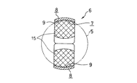
図1〜2は、本発明に関する参考例の第1例を示している。本参考例は、前述した図12に示す様な、合成樹脂製の冠型保持器に適用した場合に就いて示している。尚、本参考例の特徴は、ポケット7の内周面と玉5の転動面との摩擦面積を減少させると共に、これら内周面と転動面との間にグリース、潤滑油等の潤滑剤を効率良く取り込める様にすべく、このポケット7の内面の形状を工夫した点にある。その他の部分の構造及び作用は、前述した従来構造と同様であるから、同等部分に関する図示及び説明は、省略若しくは簡略にし、以下、本参考例の特徴部分を中心に説明する。
【0020】
上記ポケット7の内面の一部、即ち、図1〜2に斜格子で示す中央部分には、保持案内面として機能する球面部15を、上記ポケット7の全長に亙って設けている。この球面部15は、単一中心を有する球状凹面で、その曲率半径は、当該ポケット7内に転動自在に保持する、玉5の転動面の曲率半径よりも僅かに大きい。又、上記ポケット7の両側部分、即ち、保持器11aの内径側と外径側とに寄った部分には、円筒面部16、16を形成している。これら両円筒面部16、16は、上記保持器11aの直径方向に存在する軸(ポケット7を構成する円弧の中心軸)をその中心とする、単一円筒面上に存在する。従って、本参考例の保持器11aを玉軸受に組み込んだ状態では、上記転動面と球面部15とが擦れ合う事はあっても、この転動面と上記両円筒面部16、16とは擦れ合わない。又、これら両円筒面部16、16と転動面との間には、上記ポケット7の内径側、外径側、両開口部に向かう程厚さ寸法が大きくなる、くさび状隙間17、17が、上記ポケット7の内径側、外径側、両開口部に、これら両開口部の全長に亙って形成される。
【0021】
上述の様に構成する本参考例の玉軸受用保持器の場合、各ポケット7の内周面と玉5の転動面とは、上記球面部15部分でのみ擦れ合い、円筒面部16部分では擦れ合わない。従って、上記各ポケット7の内周面と玉5の転動面との摩擦面積が減少し、保持器11aと玉5との滑り接触部分で発生する摩擦振動が低減されて、振動や騒音が減少する。又、上記球面部15を挟む状態で形成した1対の円筒面部16、16と上記玉5の転動面との間には、上記くさび状隙間17、17が存在する。本参考例の保持器11aを組み込んだ玉軸受の運転時に、上記玉5の転動面に付着した潤滑剤は、上記くさび状隙間17、17から上記球面部15と転動面との間に存在する隙間部分に円滑に取り込まれる。しかも、上記円筒面部16、16は、上記各ポケット7の内径側、外径側、両開口部の全長に亙って設けており、上記くさび状隙間17、17も、これら両開口部の全長に亙って存在するので、上記球面部15と転動面との間に存在する隙間部分への潤滑剤の取り込みは効果的に行なえる。これらにより、保持器11aと玉5との滑り接触部分に作用する摩擦を低減し、この滑り接触部分で発生する摩擦振動を低減して、振動や騒音の減少を図れる。
【0022】
図3は、本参考例の保持器11aの効果を確認する為、本発明者が行なった実験の結果を示している。この図3は、保持器を組み込んだ玉軸受から発生する音の周波数スペクトルを示すものであり、横軸は周波数を、縦軸は騒音レベルを、それぞれ表している。又、測定結果を表す2本の曲線a、bのうち、実線で描いた曲線aは、前記図15〜16に示す従来構造の第2例の様に、ポケット7の内周面を全幅に亙って球面部15とした保持器を用いて構成された玉軸受が発生する騒音の周波数スペクトルを表している。一方、破線で描いた曲線bは、図1〜2に示した参考例の第1例の様に、球面部15の幅寸法を小さくした保持器を用いて構成された玉軸受が発生する騒音の周波数スペクトルを表している。尚、これら各玉軸受を構成する構成各部品のうち、保持器以外の構成各部品に就いては、互いに同一(同等)の部品を使用した。この図3の曲線a、bを比較すれば明らかな通り、本参考例の玉軸受の場合、耳障りな高周波成分が低減している。即ち、音響特性が向上している。
【0023】
次に、図4〜5は、本発明に関する参考例の第2例を示している。本参考例の場合には、ポケット7の内周面に形成した球面部15を、保持器11aの外径側に片寄せて形成している。この様な本参考例の場合、上記球面部15の幅寸法を、上述した参考例の第1例の場合に比べて広くする事ができ、上述した参考例の第1例の場合に比べて、玉5に対する保持器11aの動き量を小さくする事が可能となる。この事が、保持器音のより一層の低減に寄与する。その他の構成及び作用は、上述した参考例の第1例の場合と同様である。
【0024】
次に、図6〜7は、本発明に関する参考例の第3例を示している。本参考例の場合には、ポケット7の内周面に形成した球面部15を、保持器11aの内径側に片寄せて形成している。この様な本参考例の場合も、上述した参考例の第2例の場合と同様に、上記球面部15の幅寸法を、上述した参考例の第1例の場合に比べて広くする事ができ、上述した参考例の第1例の場合に比べて、玉5に対する保持器11aの動き量を小さくする事が可能となる。この事が、保持器音のより一層の低減に寄与する。その他の構成及び作用は、上述した参考例の第1例の場合と同様である。
【0025】
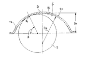
次に、図8〜9は、本発明の実施の形態の第1例を示している。本例は、本発明を、前述の図11に示した様な波形プレス保持器に適用したものである。この様な本例の場合、各ポケット7の内面形状を、これら各ポケット7の幅方向(保持器の直径方向)中間部に設けた球面部15と、それぞれがこの球面部15の幅方向両端縁から滑らかに連続する1対の曲面部18、18とにより構成している。上記球面部15は、上記各ポケット7の内面のほぼ全長に亙って形成したもので、当該ポケット7内に転動自在に保持する玉5の転動面の曲率半径R5 よりも少し大きな曲率半径R15を有する球状凹面である。又、上記各曲面部18、18は、上記球面部15の幅方向両端縁から連続して、上記各ポケット7の開口端縁部にまで達するもので、上記球面部15よりも大きな曲率半径R18(R18>R15>R5 )を有する。
【0026】
上述の様な各曲面部18、18の内端縁と上記球面部15の幅方向端縁とは、滑らかに連続している。即ち、この球面部15の両端縁に於ける接線方向と、上記各曲面部18、18の内端縁に於ける接線方向とを互いに一致させている。尚、上記球面部15及び各曲面部18、18の円弧長さL15、L18は、設計的に定めるが、例えば次の様な範囲内に規制する事が好ましい。
L15=R15・θ15=2R5 ×(5〜15%)
L18=R18・θ18=2R5 ×(5〜15%)
【0027】
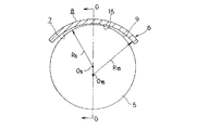
又、上記各ポケット7を保持器6aの径方向から見た形状は、図9に誇張して示す様に、円形よりもラグビーボール状に少し潰れた形状としている。即ち、前述の図18に示した従来構造と同様に、各ポケット7の深さD7 を、上記曲面部15の曲率半径R15よりも小さくしている。特に本発明の場合には、これらD7 と曲率半径R15との差(R15−D7 )を、前述の図18に示した従来構造の場合よりも大きくしている。従って、本例の場合には、上記各ポケット7を構成する球面部15と玉5の転動面とが摺接する点P1 が、図9に示す様に、上記保持器6aの幅方向中央部から幅方向端部に向けて比較的大きくずれた位置に存在する。即ち、接点角度α(上記玉5の中心と上記点P1 とを結ぶ直線と保持器6aの円周方向を表す線との交差角度)が、前述の図18に示した従来構造の場合よりも大きい。尚、この接点角度αは、保持器6aを組み込む玉軸受の接触角(通常10〜20°)よりも大きい値とする(最大90°)。従って、上記各玉5の転走面と、当該玉5を保持したポケット7の内面との間には、図9に示す様に、比較的大きな隙間19が存在する事になる。
【0028】
上述の様に構成する本例の玉軸受用保持器の場合も、各ポケット7の内周面と玉5の転動面とは、上記球面部15部分でのみ擦れ合い、曲面部18、18部分では擦れ合わない。従って、上記各ポケット7の内周面と玉5の転動面との摩擦面積が減少し、保持器6aと玉5との滑り接触部分で発生する摩擦振動が低減されて、振動や騒音が減少する。又、本例の場合も、上記球面部15を挟む状態で形成した1対の曲面部18、18と上記玉5の転動面との間には、くさび状隙間17a、17aが存在する。本発明の保持器6aを組み込んだ玉軸受の運転時に、上記玉5の転動面に付着した潤滑剤は、上記くさび状隙間17a、17aから上記球面部15と転動面との間に存在する隙間部分に円滑に取り込まれる。しかも、上記曲面部18、18は、上記各ポケット7の内径側、外径側、両開口部の全長に亙って設けており、上記くさび状隙間17a、17aも、これら両開口部の全長に亙って存在するので、上記球面部15と転動面との間に存在する隙間部分への潤滑剤の取り込みは効果的に行なえる。これらにより、保持器6aと玉5との滑り接触部分に作用する摩擦を低減し、この滑り接触部分で発生する摩擦振動を低減して、振動や騒音の減少を図れる。
【0029】
しかも、図示の例の場合には、上記玉5の転走面と、当該玉5を保持したポケット7の内面との間に、比較的大きな隙間19が存在する。上記玉5の転動面のうち、特に転走面に付着した潤滑剤は、この隙間19を通過して殆ど掻き取られる事なく、この転走面と内輪軌道1及び外輪軌道3(図11)との当接部に送り込まれる。この為、この当接部に十分な量の潤滑剤を送り込んで、玉軸受の潤滑性を良好にし、この玉軸受の耐久性向上を図れる。
【0030】
次に、図10は、本発明の実施の形態の第2例を示している。本例の場合には、ポケット7の内面を構成すべく、球面部15の両側に設けた1対の曲面部18a、18aの断面形状を直線状としている。即ち、これら各曲面部18a、18aを円錐状凹面とし、断面形状の曲率半径を∞としている。その他の構成及び作用は、上述した本発明の実施の形態の第1例の場合と同様である。尚、本発明を、図12に示した様な、冠型の保持器で実施する事もできる。
【0031】
【発明の効果】
本発明の玉軸受は以上に述べた通り構成され作用するので、ポケットの内面と玉の転動面との間の滑り摩擦を低減して保持器音の低減を図れる。この結果、低騒音、低振動の玉軸受を得させて、玉軸受を組み込んだ各種回転機械の性能向上を図れる。又、保持器の耐摩耗性を向上させて、保持器並びに玉軸受の耐久性向上にも寄与できる。更に、各玉の転走面と内輪軌道及び外輪軌道との当接部(転がり接触部)に十分な量の潤滑剤を送り込んで、玉軸受の潤滑性を良好にし、この玉軸受の耐久性向上を図れる。
【図面の簡単な説明】
【図1】 本発明に関する参考例の第1例を示す、保持器の部分拡大斜視図。
【図2】 図1のA−A断面図。
【図3】 参考例の第1例の保持器を組み込んだ玉軸受、及び従来の保持器を組み込んだ玉軸受の、それぞれ騒音の周波数スペクトルを示す線図。
【図4】 本発明に関する参考例の第2例を示す、保持器の部分拡大斜視図。
【図5】 図4のB−B断面図。
【図6】 本発明に関する参考例の第3例を示す、保持器の部分拡大斜視図。
【図7】 図6のC−C断面図。
【図8】 本発明の実施の形態の第1例を示す、図14の上半部に相当する図。
【図9】 図8のD−D断面図。
【図10】 本発明の実施の形態の第2例を示す、図8と同様の図。
【図11】 本発明の対象となる玉軸受の1例を示す、部分切断斜視図。
【図12】 保持器の別例を示す斜視図。
【図13】 従来の保持器の第1例を示す、部分拡大分解斜視図。
【図14】 組み立てた状態で示す、図13のE−E断面図。
【図15】 従来の保持器の第2例を示す、部分拡大斜視図。
【図16】 図15のF−F断面図。
【図17】 従来の保持器を示す、図14の上半部に相当する図。
【図18】 図17のG−G断面図
【図19】 玉に対して保持器が内径側に変位した状態で示す、図18のH−H断面図。
【符号の説明】
1 内輪軌道
2 内輪
3 外輪軌道
4 外輪
5 玉
6、6a 保持器
7 ポケット
8 素子
9 凹部
10 リベット
11、11a 保持器
12 主部
13 弾性片
14 凹面部
15 球面部
16 円筒面部
17、17a くさび状隙間
18、18a 曲面部
19 隙間[0001]
BACKGROUND OF THE INVENTION
According to this inventionBall bearingIs installed in the rotation support part of various rotating machines that require low noise, low vibration and low torque, such as machine tools, general machinery, automotive fan motors, air conditioner motors, and cooling fan motors for various mechanical devices. Used in.
[0002]
[Prior art]
For example, a ball bearing as shown in FIG. 11 is widely used as a ball bearing for supporting various rotating parts such as bearings of various rotating machines. In this ball bearing, an inner ring 2 having an
[0003]
The
[0004]
Further, the
[0005]
When assembling the ball bearing, each of the
[0006]
When the ball bearing provided with the
[0007]
The portion between the outer peripheral surface of the inner ring 2 and the inner peripheral surface of the outer ring 4 is filled with or continuously supplied with a lubricant such as grease or other lubricating oil so that the relative rotation is performed smoothly. . In addition, vibration and noise are prevented from occurring in the ball bearing, and failure such as seizure is prevented. In some ball bearings, both ends of the space between the outer peripheral surface of the inner ring 2 and the inner peripheral surface of the outer ring 4 are closed by a sealing member such as a seal plate or a shield plate, and the lubricant leaks from this space. In some cases, foreign matter such as dust is prevented from entering the space. However, in FIG.,The ball bearing which does not have such a sealing member is shown.
[0008]
In the case of a ball bearing incorporating the
[0009]
[Problems to be solved by the invention]
However, even if the amount of movement of the
[0010]
First, in the case of the first example of the conventional structure shown in FIG. 11, the inner peripheral surfaces of the
[0011]
In this way, when the inner peripheral surface of the
[0012]
The
[0013]
However, the plurality of
[0014]
That is, in this state, as shown in FIGS. 18 to 19, the
[0015]
As a result of such poor intake of the lubricant, the sliding friction coefficient of the sliding contact portion between the rolling surface of each
[0016]
[Means for Solving the Problems]
Of the present inventionBall bearingsConventionalSame as ball bearingIn addition,An inner ring having an inner ring raceway on the outer peripheral surface, an outer ring having an outer ring raceway on the inner peripheral surface, and a plurality of balls provided between the inner ring raceway and the outer ring raceway,The whole is annular or cylindrical, and several pockets are intermittently formed in the circumferential direction.With cageThe
[0017]
In particular, in the ball bearing of the present invention, with respect to the shape of the pockets constituting the cage as viewed in the radial direction of the cage, the length of the cage in the circumferential direction is set to the axis of the cage. By making it larger than the width in the direction, the inner surface of each pocket and the rolling surface of each ball are in the state where each ball is displaced to the circumferential end of the cage in each pocket.The point of sliding contact and the center of each ballConnecting straight line and,The contact angle, which is the angle of intersection with the line representing the circumferential direction of the cage, is made larger than the contact angle of the ball bearing. The “circumferential direction of each pocket” referred to in the present specification refers to a direction that coincides with the circumferential direction of the cage.
Further, the inner radius of each pocket is formed over almost the entire length of the inner surface of each pocket, and the radius of curvature is slightly larger than the radius of curvature of the rolling surface of the ball that is slidably held in the pocket. A spherical concave surface having a spherical concave surface and a curvature that is curved in the same direction as the spherical surface portion and reaches the opening edge edge of each pocket continuously from the edge of the spherical surface portion, and has a larger curvature than the spherical surface portion. A curved surface portion having a radius and smoothly continuing from the edge of the spherical portion toward the opening side of each of the pockets. At the same time, the tangential direction of the spherical surface portion at both ends of the spherical surface portion and the tangential direction of the curved surface portion at the inner edge of the curved surface portion are made to coincide with each other so that the inner edge of the curved surface portion and the spherical surface The edges in the width direction of the part are smoothly continuous.
[0018]
[Action]
The present invention configured as described above.Ball bearingsThe inner peripheral surface of each pocket and the rolling surface of the ball rub against each other only at the spherical surface portion.At the curved surfaceDo not rub. or,This curved surfaceThere is a gap larger than the gap existing between the spherical surface and the rolling surface between the ball and the rolling surface of the ball held inside each pocket. Therefore, not only the friction area between the inner peripheral surface of each pocket and the rolling surface of the ball is reduced, but also the lubricant can be smoothly taken into the gap portion existing between the spherical surface portion and the rolling surface. Yes.Curved part aboveIs provided over substantially the entire length of each of the pockets, so that it is possible to effectively take in the lubricant into the gap portion existing between the spherical surface portion and the rolling surface. By these actions, the friction acting on the sliding contact part between the cage and the ball is reduced, and the frictional vibration generated at this sliding contact part is reduced to reduce the vibration and noise.I can plan. In addition, since the contact angle is larger than the contact angle of the ball bearing, there is a relatively large gap between the rolling surface of each ball and the inner surface of the pocket that holds these balls. Of these rolling surfaces of each ball, the lubricant adhering to the rolling surface, in particular, passes through this gap and is hardly scraped off, so that the contact portion between the rolling surface and the inner ring raceway and the outer ring raceway ( Rolling contact part). For this reason, a sufficient amount of lubricant is fed into the contact portion to improve the lubricity of the ball bearing and to improve the durability of the ball bearing.
[0019]
DETAILED DESCRIPTION OF THE INVENTION
1 and 2Reference examples related to the present inventionThe 1st example of is shown.This reference exampleFIG. 12 shows the case where the present invention is applied to a synthetic resin crown-shaped cage. still,Reference exampleThe feature is that the friction area between the inner peripheral surface of the
[0020]
A
[0021]
Configure as aboveReference exampleIn the case of this ball bearing retainer, the inner peripheral surface of each
[0022]
FIG.Reference exampleIn order to confirm the effect of the
[0023]
Next, FIGS.Reference examples related to the present inventionThe 2nd example of is shown.Reference exampleIn this case, the
[0024]
Next, FIGS.Third example of reference example related to the present inventionIs shown.Reference exampleIn this case, the
[0025]
Next, FIGS. 8 to 9 show the embodiment of the present invention.First exampleIs shown. This exampleThe present inventionIs applied to a corrugated press cage as shown in FIG. In the case of this example, the inner surface shape of each
[0026]
The inner edge of each
L15= R15・ Θ15= 2RFive X (5-15%)
L18= R18・ Θ18= 2RFive X (5-15%)
[0027]
Further, the shape of each of the
[0028]
Also in the case of the ball bearing cage of the present example configured as described above, the inner peripheral surface of each
[0029]
Moreover, in the illustrated example, a relatively
[0030]
next,FIG. 10 shows a second example of the embodiment of the present invention.Is shown. In the case of this example, the cross-sectional shape of the pair of
[0031]
【The invention's effect】
Of the present inventionBall bearingsSince it is configured and acts as described above, it is possible to reduce the sliding friction between the inner surface of the pocket and the rolling surface of the ball, thereby reducing the cage noise. As a result, it is possible to obtain a ball bearing with low noise and vibration and to improve the performance of various rotating machines incorporating the ball bearing. In addition, the wear resistance of the cage can be improved, and the durability of the cage and ball bearing can be improved.In addition, a sufficient amount of lubricant is fed into the contact portion (rolling contact portion) between the rolling surface of each ball and the inner ring raceway and outer ring raceway to improve the lubricity of the ball bearing, and the durability of this ball bearing. Improvements can be made.
[Brief description of the drawings]
[Figure 1]Reference examples related to the present inventionThe partial expanded perspective view of the holder | retainer which shows the 1st example of.
FIG. 2 is a cross-sectional view taken along the line AA in FIG.
[Fig. 3]Reference exampleThe diagram which shows the frequency spectrum of a noise of the ball bearing incorporating the cage of the 1st example, and the ball bearing incorporating the conventional cage, respectively.
[Fig. 4]Reference examples related to the present inventionThe partial expansion perspective view of the holder | retainer which shows the 2nd example of.
5 is a cross-sectional view taken along the line BB in FIG.
[Fig. 6]Reference examples related to the present inventionThe partial expansion perspective view of the holder | retainer which shows the 3rd example of.
7 is a cross-sectional view taken along the line CC of FIG.
FIG. 8 shows an embodiment of the present invention.First exampleThe figure equivalent to the upper half part of FIG.
9 is a sectional view taken along the line DD of FIG.
FIG. 10 shows an embodiment of the present invention.Second exampleThe figure similar to FIG.
FIG. 11Ball bearings subject to the present inventionFIG.
FIG.CageThe perspective view which shows another example.
FIG. 13 is a partially enlarged exploded perspective view showing a first example of a conventional cage.
14 is a cross-sectional view taken along the line EE of FIG. 13, shown in an assembled state.
FIG. 15 is a partially enlarged perspective view showing a second example of a conventional cage.
16 is a sectional view taken along line FF in FIG.
17 is a view corresponding to the upper half of FIG. 14, showing a conventional cage.
18 is a cross-sectional view taken along line GG in FIG.
FIG. 19 is a cross-sectional view taken along line HH in FIG.
[Explanation of symbols]
1 Inner ring raceway
2 inner ring
3 Outer ring raceway
4 Outer ring
5 balls
6, 6a Cage
7 pockets
8 elements
9 recess
10 rivets
11, 11a Cage
12 Main part
13 Elastic pieces
14 Concave part
15 Spherical surface
16 Cylindrical surface
17, 17a Wedge-shaped gap
18, 18a Curved surface
19 Clearance
Claims (4)
Priority Applications (2)
| Application Number | Priority Date | Filing Date | Title |
|---|---|---|---|
| JP20455498A JP4006836B2 (en) | 1997-08-18 | 1998-07-21 | Ball bearing |
| US09/135,665 US6074099A (en) | 1997-08-18 | 1998-08-18 | Cage for ball bearing |
Applications Claiming Priority (3)
| Application Number | Priority Date | Filing Date | Title |
|---|---|---|---|
| JP9-221342 | 1997-08-18 | ||
| JP22134297 | 1997-08-18 | ||
| JP20455498A JP4006836B2 (en) | 1997-08-18 | 1998-07-21 | Ball bearing |
Publications (2)
| Publication Number | Publication Date |
|---|---|
| JPH11125256A JPH11125256A (en) | 1999-05-11 |
| JP4006836B2 true JP4006836B2 (en) | 2007-11-14 |
Family
ID=26514532
Family Applications (1)
| Application Number | Title | Priority Date | Filing Date |
|---|---|---|---|
| JP20455498A Expired - Lifetime JP4006836B2 (en) | 1997-08-18 | 1998-07-21 | Ball bearing |
Country Status (2)
| Country | Link |
|---|---|
| US (1) | US6074099A (en) |
| JP (1) | JP4006836B2 (en) |
Cited By (1)
| Publication number | Priority date | Publication date | Assignee | Title |
|---|---|---|---|---|
| CN103196402A (en) * | 2013-02-25 | 2013-07-10 | 中国北方车辆研究所 | Spherical surface coloring and contact area detecting device |
Families Citing this family (18)
| Publication number | Priority date | Publication date | Assignee | Title |
|---|---|---|---|---|
| JP2000337387A (en) * | 1999-05-24 | 2000-12-05 | Nsk Ltd | Holder for rolling bearing |
| JP2001027249A (en) * | 1999-07-14 | 2001-01-30 | Minebea Co Ltd | Bearing retainer and rolling bearing |
| DE19937664A1 (en) * | 1999-08-10 | 2001-02-15 | Schaeffler Waelzlager Ohg | Plastic snap cage for radial ball bearings comprises ball pockets whose radial inner and/or outer edges are provided with specified rounding radii |
| JP2002357226A (en) * | 2001-03-28 | 2002-12-13 | Nsk Ltd | Ball bearing |
| DE10136955B4 (en) * | 2001-07-28 | 2010-11-04 | Schaeffler Technologies Gmbh & Co. Kg | Angular contact ball cage with lubricant pockets |
| JP4055938B2 (en) * | 2002-04-18 | 2008-03-05 | ミネベア株式会社 | Radial ball bearing retainer |
| GB0214207D0 (en) * | 2002-06-19 | 2002-07-31 | Sarnatech Bnl Ltd | Improved bearing |
| JP4188666B2 (en) * | 2002-11-15 | 2008-11-26 | Ntn株式会社 | Resin cage for rolling bearings |
| DE10258861A1 (en) * | 2002-12-17 | 2003-12-04 | Bosch Gmbh Robert | Cage for ball bearing has surfaces structured to transport lubricant to pockets |
| ITTO20040594A1 (en) * | 2004-09-09 | 2004-12-09 | Skf Ab | BALL BEARING UNIT WITH PERFECTED BALL HOLDING CAGE |
| DE112008000271B4 (en) * | 2007-01-30 | 2021-06-17 | Ntn Corp. | Ball bearing cage |
| EP2068018A1 (en) * | 2007-12-05 | 2009-06-10 | Aktiebolaget SKF | Ball bearing cage |
| CN101978181B (en) * | 2008-03-21 | 2014-04-09 | Ntn株式会社 | Cage for ball bearing, ball bearing with cage and method of manufacturing cage |
| JP5188359B2 (en) * | 2008-10-30 | 2013-04-24 | Ntn株式会社 | Rolling bearing with seal |
| DE102009013978A1 (en) * | 2009-03-19 | 2010-09-23 | Schaeffler Technologies Gmbh & Co. Kg | Cage for radial rolling bearings |
| JP6211260B2 (en) * | 2012-11-16 | 2017-10-11 | Ntn株式会社 | Crown cage and ball bearing |
| CN103438103A (en) * | 2013-05-04 | 2013-12-11 | 安徽华之杰机械有限公司 | Retainer with double curvature special-shaped pockets |
| DE102016124430A1 (en) | 2016-12-15 | 2018-06-21 | Schaeffler Technologies AG & Co. KG | Rolling bearing cage |
Family Cites Families (10)
| Publication number | Priority date | Publication date | Assignee | Title |
|---|---|---|---|---|
| US3918777A (en) * | 1973-11-29 | 1975-11-11 | Gen Motors Corp | Sheet metal ball bearing retainer and method of making same |
| US4136915A (en) * | 1977-04-18 | 1979-01-30 | Fmc Corporation | Ball bearing retainer |
| US4225199A (en) * | 1978-09-15 | 1980-09-30 | Earsley Melvin L | Ball separator for ball bearing |
| JPS58195118U (en) * | 1982-06-23 | 1983-12-26 | 日本精工株式会社 | Cage for rolling element guide |
| IT8436106V0 (en) * | 1983-10-08 | 1984-09-28 | Skf Kugellagerfabriken Gmbh | CAGE FOR BALL BEARINGS, IN A SPECIAL MODE PLASTIC CAGE FOR FOUR POINT BEARINGS |
| DE3939438A1 (en) * | 1989-11-29 | 1991-06-06 | Kugelfischer G Schaefer & Co | KAEFIG FOR BALL BEARINGS |
| US6068408A (en) * | 1995-10-19 | 2000-05-30 | Nsk Ltd. | Cage for a rolling bearing |
| JPH09273557A (en) * | 1996-04-01 | 1997-10-21 | Koyo Seiko Co Ltd | Corrugated holder for ball bearing |
| JP3682611B2 (en) * | 1996-05-31 | 2005-08-10 | 光洋精工株式会社 | Corrugated cage for ball bearings |
| JPH1019046A (en) * | 1996-07-05 | 1998-01-20 | Koyo Seiko Co Ltd | Plastic molded holder for rolling bearing and manufacture thereof |
-
1998
- 1998-07-21 JP JP20455498A patent/JP4006836B2/en not_active Expired - Lifetime
- 1998-08-18 US US09/135,665 patent/US6074099A/en not_active Expired - Lifetime
Cited By (2)
| Publication number | Priority date | Publication date | Assignee | Title |
|---|---|---|---|---|
| CN103196402A (en) * | 2013-02-25 | 2013-07-10 | 中国北方车辆研究所 | Spherical surface coloring and contact area detecting device |
| CN103196402B (en) * | 2013-02-25 | 2016-08-17 | 中国北方车辆研究所 | A kind of sphere coloring and contact area check device |
Also Published As
| Publication number | Publication date |
|---|---|
| US6074099A (en) | 2000-06-13 |
| JPH11125256A (en) | 1999-05-11 |
Similar Documents
| Publication | Publication Date | Title |
|---|---|---|
| JP4006836B2 (en) | Ball bearing | |
| JP3744663B2 (en) | Radial ball bearing cage and radial ball bearing | |
| US6068408A (en) | Cage for a rolling bearing | |
| JPH07279970A (en) | Cage for ball bearing and ball bearing | |
| JP3684642B2 (en) | Roller bearing cage | |
| JP2006250268A (en) | Rolling bearing and cam shaft device | |
| JP4661424B2 (en) | Rotation support | |
| JP2010133559A (en) | Inner ring of roller bearing | |
| JP4017818B2 (en) | Ball bearing | |
| JP2018194040A (en) | Cage for thrust roller bearing and thrust roller bearing | |
| JP2001116051A (en) | Cage for ball bearing and ball bearing | |
| JPH074439A (en) | High speed angular ball bearing | |
| JP2001289249A (en) | Cage for ball bearing and ball bearing | |
| JP2008175239A (en) | Ball bearing crown cage and ball bearing | |
| JPH11166540A (en) | Cage for rolling bearing | |
| JPH09303402A (en) | Retainer for ball bearing | |
| JPH1082424A (en) | Holder for rolling bearing | |
| JP2021102976A (en) | Planetary roller type power transmission device | |
| JP2000039024A (en) | Holder for rolling bearing | |
| JP2002295480A (en) | Ball bearing | |
| JP5764959B2 (en) | Ball bearing | |
| JP2008190629A (en) | Retainer for radial ball bearing, and radial ball bearing | |
| JPH11325080A (en) | Holder for radial ball bearing | |
| JP2008190630A (en) | Retainer for radial ball bearings, and radial ball bearing | |
| JP2002303326A (en) | Retainer for rolling bearing and rolling bearing |
Legal Events
| Date | Code | Title | Description |
|---|---|---|---|
| A521 | Request for written amendment filed |
Free format text: JAPANESE INTERMEDIATE CODE: A523 Effective date: 20040401 |
|
| A621 | Written request for application examination |
Free format text: JAPANESE INTERMEDIATE CODE: A621 Effective date: 20040401 |
|
| A977 | Report on retrieval |
Free format text: JAPANESE INTERMEDIATE CODE: A971007 Effective date: 20060714 |
|
| A131 | Notification of reasons for refusal |
Free format text: JAPANESE INTERMEDIATE CODE: A131 Effective date: 20060801 |
|
| A521 | Request for written amendment filed |
Free format text: JAPANESE INTERMEDIATE CODE: A523 Effective date: 20060928 |
|
| A131 | Notification of reasons for refusal |
Free format text: JAPANESE INTERMEDIATE CODE: A131 Effective date: 20061212 |
|
| A521 | Request for written amendment filed |
Free format text: JAPANESE INTERMEDIATE CODE: A523 Effective date: 20070209 |
|
| A131 | Notification of reasons for refusal |
Free format text: JAPANESE INTERMEDIATE CODE: A131 Effective date: 20070417 |
|
| A521 | Request for written amendment filed |
Free format text: JAPANESE INTERMEDIATE CODE: A523 Effective date: 20070530 |
|
| TRDD | Decision of grant or rejection written | ||
| A01 | Written decision to grant a patent or to grant a registration (utility model) |
Free format text: JAPANESE INTERMEDIATE CODE: A01 Effective date: 20070807 |
|
| A61 | First payment of annual fees (during grant procedure) |
Free format text: JAPANESE INTERMEDIATE CODE: A61 Effective date: 20070820 |
|
| FPAY | Renewal fee payment (event date is renewal date of database) |
Free format text: PAYMENT UNTIL: 20100907 Year of fee payment: 3 |
|
| R150 | Certificate of patent or registration of utility model |
Free format text: JAPANESE INTERMEDIATE CODE: R150 |
|
| FPAY | Renewal fee payment (event date is renewal date of database) |
Free format text: PAYMENT UNTIL: 20110907 Year of fee payment: 4 |
|
| FPAY | Renewal fee payment (event date is renewal date of database) |
Free format text: PAYMENT UNTIL: 20110907 Year of fee payment: 4 |
|
| FPAY | Renewal fee payment (event date is renewal date of database) |
Free format text: PAYMENT UNTIL: 20120907 Year of fee payment: 5 |
|
| FPAY | Renewal fee payment (event date is renewal date of database) |
Free format text: PAYMENT UNTIL: 20120907 Year of fee payment: 5 |
|
| FPAY | Renewal fee payment (event date is renewal date of database) |
Free format text: PAYMENT UNTIL: 20130907 Year of fee payment: 6 |
|
| EXPY | Cancellation because of completion of term |