JP4004147B2 - Data transmitting device, data receiving device, and data recording device - Google Patents
Data transmitting device, data receiving device, and data recording device Download PDFInfo
- Publication number
- JP4004147B2 JP4004147B2 JP21458098A JP21458098A JP4004147B2 JP 4004147 B2 JP4004147 B2 JP 4004147B2 JP 21458098 A JP21458098 A JP 21458098A JP 21458098 A JP21458098 A JP 21458098A JP 4004147 B2 JP4004147 B2 JP 4004147B2
- Authority
- JP
- Japan
- Prior art keywords
- data
- packet
- buffer
- pack
- error
- Prior art date
- Legal status (The legal status is an assumption and is not a legal conclusion. Google has not performed a legal analysis and makes no representation as to the accuracy of the status listed.)
- Expired - Fee Related
Links
Images


Description
【0001】
【発明の属する技術分野】
本発明は、データ送信装置,データ受信装置,データ記録装置に関し、特に、MPEG(moving picture expert group)2エンコーダの出力データや光ディスク等の記録媒体に記録されたMPEG2プログラムストリームのデータを、IEEE1394方式等の通信媒体(インターフェイス)を介して送信,受信,あるいは記録するよう構成した装置に関するものである。
【0002】
【従来の技術】
近年、データのシリアル伝送方式として、上記IEEE1394方式が注目されている。このIEEE1394方式では、データ伝送のベースレートとして、100Mbps,200Mbps,400Mbpsのうちのいずれかを用い、125μs(マイクロ秒)をデータ伝送の1サイクルとしている。
【0003】
また、IEEE1394方式では、2つの通信方法、つまり、送信要求に応じて直ちにデータの送信が行われるアイソクロノス通信(同期通信)と、場合によってはデータの送信が送信要求の発生から遅れて行われるアシンクロナス通信(非同期通信)が定義されている。
【0004】
上記アイソクロノス通信は、AV(Audio Video )データのようなリアルタイム性が要求されるデータの伝送に用いられる通信方法である。このアイソクロノス通信では、データ伝送の開始に先立って、まず、データを伝送するのに必要な帯域を取得し、あらかじめ取得した帯域を使って1サイクル(125μs)に一度、少なくとも1パケットのデータの伝送を行う。これにより、データ伝送のリアルタイム性が保証される。
【0005】
一方、上記アシンクロナス通信は、コマンド等のコンピュータデータや静止画データの伝送のように、リアルタイム性が要求されないデータの伝送に用いられる通信方法である。これは、従来のSCSI(small computer system interface )方式等の伝送方式と同等な方式であると考えることができる。
【0006】
現在、アイソクロノス通信を用いたAVデータの伝送としては、ディジタルVCR(Video Cassette Recorder )用データの伝送方法、MPEG2トランスポートストリームのデータの伝送方法等が定義されている。
【0007】
以下簡単に、従来のIEEE1394方式のインターフェイス(以下,1394I/Fと略記する。)を用いたネットワークNでの通信方法について説明する。図36(a)は、3つの端末装置が上記1394I/Fを介して接続されたネットワークを模式的に示している。ここでは、端末装置Aはデジタルビデオカメラ(DVC)、端末装置Bは画像データとしてMPEG2のトランスポートストリーム(以下TSと略記する。)を出力する構成のパーソナルコンピュータ(以下パソコンと略記する。)、端末装置Cは画像データの受信装置であり、上記端末装置Aは、上記ネットワーク上に125μs毎にサイクルスタートパケットを出力するメイン端末装置となっている。また、このメイン端末装置Aは、各端末がデータ伝送に使用する周波数帯域の割り当てをも行う構成となっている。
【0008】
上記1394I/Fでは、1サイクル期間に対して、アイソクロノス通信に利用される時間と、アシンクロノス通信に利用される時間とが割り当てられており、1サイクル期間の80パーセントがアイソクロノス通信に、残りの20パーセントがアシンクロノス通信に利用されるようになっている。そして、各端末装置は、リアルタイム性の要求されるデータについてはアイソクロノス通信によりデータ伝送を行い、リアルタイム性の要求されないデータについてはアシンクロノス通信によりデータ伝送を行う。
【0009】
まず、各端末装置A〜Cは、データ伝送に必要な周波数帯域をメイン端末装置Aに対して宣言し、データ伝送に使用する帯域の使用の許可を求める。許可されれば、データ送信にはその帯域を利用する。許可されなければ、帯域幅を縮小する等して、再度使用許可を求める。この帯域の使用許可が得られると、各端末装置は、アイソクロノス通信を行う必要があるときは、上記1サイクル期間中に少なくとも一回はアイソクロノス通信によりパケットデータを伝送可能となる。
【0010】
以下、データ送信の具体的な場合として、端末装置A及び端末装置Bがアイソクロノス通信によるデータ伝送を行い、端末装置Cがアシンクロノス通信によるデータ送信を行う場合について、図36(b)の模式図を用いて説明する。
【0011】
上記メイン端末装置Aは、上記各サイクル毎にその先頭位置を示すサイクルスタートパケットSt1,St2,St3,・・・を出力するとともに、各サイクル毎にアイソクロノス通信パケットAiso1,Aiso2, Aiso3,・・・を出力する。また、上記端末装置Bは、上記各サイクル毎にアイソクロノス通信パケットBiso1,Biso2, Biso3,・・・を出力する。また、上記端末装置Cは、上記サイクルスタートパルスSt1及びSt2間の1サイクル期間では、アイソクロノス通信パケットAiso1,Biso1の後に、アシンクロノス通信パケットCasyn1 を出力する。
【0012】
なお、複数の端末装置がアシンクロノス通信パケットを出力する場合には、各端末装置から出力されるアシンクロノス通信パケットには、上記ネットワークN中でその送信要求がメイン端末装置に早く届いた端末装置に対応するものから順に優先順位が設定され、1サイクル中で送信できなかった端末装置のアシンクロノス通信パケットは、次のサイクル中で送信されることとなる。
【0013】
一方、DVD(ディジタルバーサタイルディスク)−Video規格では、記録媒体であるDVDディスクに、圧縮符号化された映像データや音声データを記録する方法が規定されている。
【0014】
DVD等の記録媒体から、圧縮符号化された映像データや音声データを読み出して、AV復号化を行う場合を考える。この場合、一般的に記録媒体からのデータの読み出しは、記録媒体を通常のデータ処理速度に対応する回転速度よりも高速度で回転させることにより、間欠的に行われる。
【0015】
従って、図37に示すように、DVDプレーヤ等の再生装置10は、AV復号化器13の前段にバッファ12を有し、DVDディスク等の記録媒体1からのデータ読出速度と、データ処理速度との違いを、上記バッファ12での読出データの蓄積により吸収させる構成となっている。なお、図37中、11は、DVDディスク1からデータを読み取るための光ヘッド、14は上記AV復号化器13の出力に基づいて画像データの表示や音声データの出力を行うテレビジョン等の表示装置である。
【0016】
このような構成のDVDプレーヤでは、記録媒体1からバッファ12へのデータ転送は、バッファ12のデータ蓄積量に基づいて制御される。また、上記バッファ12からAV復号化器13へのデータDaの転送は、AV復号化器13からの要求Reに応じてバッファ12からデータが出力されることにより行われる。
【0017】
ここで、このような構成を有するDVDプレーヤ等に、図38に示すように、ディジタルインターフェース(I/F)15が付加された機器を考える。
【0018】
送信側の機器10では、記録媒体1からバッファ12へのデータ転送を行った後、ディジタルインターフェース15にデータを出力する。一方、受信側の機器20では、ディジタルインターフェース21を介してデータを受信し、受信したデータをAV復号化器22により復号化してTV等に出力する。
【0019】
この場合、受信側機器20のAV復号化器22からの要求Rq2に応じて、送信側バッファ12からデータが出力されることとなるため、この要求Rq2が受信側及び送信側のディジタルインターフェース21,15を介して行われなければならないという問題があった。
【0020】
また、複数の機器がデータを受信する場合、AV復号化器の動作が機器によって異なる可能性があるため、受信側の各機器からの要求に応じて送信側の機器はデータを出力しなければならない。したがって、送信側の機器では、記録媒体からのデータの読み出しを非常に高速にしなければならないという問題もあった。
【0021】
【発明が解決しようとする課題】
しかしながら、MPEG2プログラムストリームエンコーダから出力されるデータや、DVDに記録されたデータは、MPEG2プログラムストリーム形式のデータ(以下、PS形式のデータともいう。)であり、このようなPS形式のデータを1394I/Fを介して伝送するには、つまり、上記従来のMPEG2トランスポートストリーム形式のデータ(以下、TS形式のデータともいう。)の伝送方法で伝送するには、データを、PS形式からTS形式に変換しなければないないという課題があった。
【0022】
以下、DVDに記録されたPS形式のデータを、1394I/Fを介して送信側から受信側に伝送する場合の問題点について、図39を用いて説明する。図39は、図38に示す送信側機器10及び受信側機器20におけるインターフェイス15及び21の詳細な構成を示している。この送信側機器10のインターフェイス15は、バッファ12から出力されるPS形式のデータをTS形式のデータに変換する変換部15aと、該変換部15aの出力に接続された送信側1394I/F15bとから構成されている。また、上記受信側機器20のインターフェイス21は、送信側からのTS形式のデータをネットワークNを介して受信する受信側1394I/F21aと、その出力であるTS形式のデータをPS形式のデータに変換する変換部21bから構成されている。
【0023】
このようにDVDに記録されたPS形式のデータを1394I/Fを介して送伝送するには、送信側ではPS形式のデータをTS形式のデータに変換し、受信側ではTS形式のデータをPS形式のデータに変換する必要がある。
【0024】
ところが、上記データの変換には以下のような種々の問題がある。まず、PS形式のデータとTS形式のデータではヘッダにおけるデータの記述内容がことなるため、ヘッダの情報を変更しなければならず、煩雑なデータ処理が必要となる。
【0025】
また、PS形式のデータ及びTS形式のデータともに、デコーダで使用するためのクロック基準(時間データ)が組み込まれている。これらの情報は、PS形式のデータではSCR(System Clock Reference)、TS形式のデータではPCR(Program Clock Reference )と呼ばれ、MPEG2の規格では、SCRの最大間隔は700ms、PCRの最大間隔は100msと規定されており、PS形式のデータからTS形式のデータへのデータ変換の際には、より細かいクロック基準を作成しなければならず、精度の高いタイミング信号を生成する回路が必要となる。
【0026】
さらに、PS形式のデータには、DVD特有のデータ(Navigationデータ等)がプライベートストリームの形式で含まれているが、PS形式のデータの変換により得られたTS形式のデータをTS用デコーダでデコーダする場合には、プライベートストリーム形式のDVD特有のデータをデコーダすることができない。このため、受信側では、1394I/F21aから出力されるTS形式のデータをPS形式のデータに逆変換する必要があり、受信側機器の構成が複雑なものとなる。
【0027】
また、送信側機器が、図40に示すような、TV信号をエンコードしてDVD等の記録媒体1に記録するDVDレコーダ10bである場合でも、上記DVDレコーダ10と同様、MPEG2エンコーダ(エレメンタリ/システム)16から出力されるPS形式のデータを、TS形式のデータに変換する変換部17を備え、この変換部17の出力が1394I/F18を介してネットワークN上に出力されるように構成する必要がある。
【0028】
さらに上記のようなDVD等の記録媒体には、データが誤り訂正符号化(ECC:Error Correction Code)され、さらに変調が施されて記録されている。このような光ディスク等の記録媒体からデータを読み出す場合には、トラックジャンプの失敗や、ECC(エラーコレクションコード)復号の際のエラーが生じて、同じデータを再度読み出した時には、バッファがアンダーフローを起こす場合がある。
【0029】
このような場合、送信側のAV復号化器からバッファへのデータ要求があってもデータは出力されないか、またはデータが出力されても正しいデータが出力されない。ディジタルインターフェースに出力されるデータも送信側のAV復号化器に入力されるデータと同様である。したがって上記従来の方法では、受信側のAV復号化器では正しい復号動作を行うことができず、不正な映像信号や音声信号が再生される。つまり上記従来のDVDプレーヤ等の機器では、送信側の機器にて光ディスク等の記録媒体からデータを読み出す際にエラーが起こった場合、読み出したデータをディジタルインターフェースを介して受信側に伝送しても、受信側では正しくAV復号化ができないという課題があった。
【0030】
本発明は、上記のような状況を鑑みてなされたものであり、MPEG2エンコーダから出力された、あるいは記録媒体に記録されたMPEG2プログラムストリームのデータを、MPEG2トランスポートストリームに変換せずに、1394I/Fを用いて伝送することができるデータ伝送装置を提供することを目的とする。
【0031】
本発明は、1394I/Fを用いて伝送されたMPEG2プログラムストリームのデータを受信して正しく復号化することができるデータ受信装置、及び1394I/Fを用いて伝送されたMPEG2プログラムストリームのデータを、所定の記録形式で記録媒体に記録することができるデータ記録装置を得ることを目的とする。
【0032】
本発明は、記録媒体に記録されたデータを伝送する際に、送信側でバッファのアンダーフローやECCエラーが発生した場合でも、受信側で正しく復号化が行われるようデータ送信を行うことができるデータ伝送装置、および該データ伝送装置から送信されたデータを正しく復号化することができるデータ受信装置を得ることを目的とする。
【0033】
【課題を解決するための手段】
この発明に係るデータ送信装置は、所定のネットワークに接続されたデータ送信装置であって、複数種類の符号化データを受け、これらの符号化データを第1のデータ単位毎に結合して第1の符号化ストリームを生成する符号化手段と、上記第1の符号化ストリームを、所定のデータサイズを有する第2のデータ単位毎に分割して、該第2のデータ単位である分割パックに対応する分割パックデータを生成する分割手段と、上記各分割パックデータにヘッダ情報を付加して、データ伝送の単位であるパケットに対応するパケットデータを生成するパケット生成手段と、 上記各パケットデータを、上記第1の符号化ストリームとはデータ構造が異なる第2の符号化ストリームとしてネットワーク上に出力する送信手段とを備えたものである。
【0034】
この発明は、上記データ送信装置において、上記符号化手段として、上記複数種類の符号化データを受け、上記第1の符号化ストリームとしてMPEG2プログラムストリームを生成し出力するシステムエンコード手段を備えたものである。
【0035】
この発明は、上記データ送信装置において、上記分割手段を、上記第1の符号化ストリームの分割を、上記各分割パックには同一種類の符号化データのみが含まれるよう行う構成としたものである。
【0036】
この発明は、上記データ送信装置において、上記パケット生成手段を、生成されるすべてのパケットのサイズが同一サイズとなるよう、上記所定のデータサイズより小さいサイズを有する分割パックには、スタッフィングデータを付加してパケットデータを生成するよう構成したものである。
【0037】
この発明に係るデータ送信装置は、所定のネットワークに接続されたデータ送信装置であって、記録媒体に所定のデータサイズを有するセクタ単位毎に分割して記録されているデータを、上記セクタ毎に読み出す読み出し手段と、上記読み出し手段により読み出された各セクタに対応するデータを、上記セクタのデータサイズよりも小さいデータサイズを有するデータ単位毎に分割して、該データ単位である分割パックに対応する分割パックデータを生成する分割手段と、上記各分割パックデータにヘッダ情報を付加して、データ伝送の単位であるパケットに対応するパケットデータを生成するパケット生成手段と、上記各パケットデータを符号化ストリームとしてネットワーク上に出力する送信手段とを備えたものである。
【0038】
この発明は、上記データ送信装置において、上記分割手段を、上記各セクタに対応するデータの分割を、該各セクタにおける先頭データが分割パックの先頭データとなるよう行う構成したものである。
【0039】
この発明は、上記データ送信装置において、上記パケット生成手段を、上記セクタの先頭データを含む分割パックには、該先頭データを含むことを示す情報を付加してパケットデータを生成するよう構成したものである。
【0040】
この発明は、上記データ送信装置において、上記送信手段を、少なくとも1つのパケットデータを一定の伝送レートでもって上記ネットワーク上へ出力するパケット単位のデータ伝送を、一定時間毎に繰り返し行い、この際、上記送信手段における伝送要求と同期して上記データ伝送を行うアイソクロノス通信で用いられるアイソクロノスパケットのヘッダに、上記先頭データを含むことを示す情報を付加する構成としたものである。
【0041】
この発明は、上記データ送信装置において、上記先頭データを含むことを示す情報を、上記各セクタに対応する複数の分割パックの数を示すカウンタ値としたものである。
【0042】
この発明は、上記データ送信装置により符号化ストリームとして出力されるパケットデータを受信するデータ受信装置であって、上記パケットデータを受信し、そのヘッダ情報の解析により各パケットに対応する上記分割パックデータを出力する受信手段と、該受信手段から出力された分割パックデータを結合して、上記セクタに対応するデータを生成する結合手段とを備えたものである。
【0043】
この発明は、上記データ送信装置により符号化ストリームとして出力されるパケットデータを受信して記録するデータ記録装置であって、上記パケットデータを受信し、そのヘッダ情報の解析により各パケットに対応する上記分割パックデータを出力する受信手段と、該受信手段から出力された分割パックデータを結合して、上記セクタに対応するデータを生成する結合手段と、該結合手段から出力されたセクタに対応するデータを、セクタ構造を有する記録媒体に記録する記録手段とを備えたものである。
【0044】
この発明は、上記データ送信装置において、上記セクタのデータサイズを、2048バイトとしたものである。
【0045】
この発明は、上記データ受信装置において、上記セクタのデータサイズを、2048バイトとしたものである。
【0046】
この発明は、上記データ記録装置において、上記セクタのデータサイズを、2048バイトとしたものである。
【0047】
この発明は、上記データ送信装置において、上記記録媒体を、MPEG2プログラムストリームのデータが所定の信号処理を施されて記録された構成としたものである。
【0048】
この発明は、上記データ受信装置において、上記記録媒体を、MPEG2プログラムストリームのデータが所定の信号処理を施されて記録された構成としたものである。
【0049】
この発明は、上記データ記録装置において、上記データ送信側の記録媒体を、MPEG2プログラムストリームのデータが所定の信号処理を施されて記録された構成としたものである。
【0050】
この発明に係るデータ送信装置は、所定のネットワークに接続されたデータ送信装置であって、記録媒体に記録されたデータを読み出すデータ読み出し手段と、該データ読み出し手段により読み出されたデータを一時蓄積するバッファ手段と、該バッファ手段より出力されたデータをネットワーク上に出力するデータ送信手段とを備え、上記データ送信手段を、上記バッファ手段がアンダーフロー状態となったとき、上記バッファ手段でアンダーフローが生じたことを示すアンダーフロー情報を上記ネットワーク上に出力するよう構成したものである。
【0051】
この発明に係るデータ送信装置は、所定のネットワークに接続されたデータ送信装置であって、記録媒体に記録されたデータを読み出すデータ読み出し手段と、該データ読み出し手段により読み出されたデータを一時蓄積するバッファ手段と、上記バッファ手段より出力されたデータにヘッダ情報を付加して、データ伝送単位であるパケットに対応するパケットデータを生成するパケット生成手段と、該パケット生成手段より出力されたパケットデータをネットワーク上に出力するデータ送信手段とを備え、上記パケット生成手段を、上記バッファ手段がアンダーフロー状態となったとき、上記バッファ手段でアンダーフローが生じたことを示すアンダーフロー情報を上記パケットのヘッダ部に付加して上記データ送信手段に出力するよう構成したものである。
【0052】
この発明は、上記データ送信装置において、上記データ送信手段を、少なくとも1つのパケットデータを一定の伝送レートでもって上記ネットワーク上へ出力するパケット単位のデータ伝送を、一定時間毎に繰り返し行う構成とし、上記パケット生成手段を、上記データ送信手段における伝送要求と同期して上記データ伝送を行うアイソクロノス通信で用いられるアイソクロノスパケットのヘッダに、上記アンダーフロー情報を付加する構成としたものである。
【0053】
この発明は、上記データ送信装置において、上記データ送信手段を、上記バッファ手段がアンダーフロー状態となったとき、上記バッファ手段でアンダーフローが生じたことを示すアンダーフロー情報として、所定パターンのデータを上記ネットワーク上に出力するよう構成したものである。
【0054】
この発明は、上記データ送信装置において、上記所定パターンのデータを、MPEG規格で規定されているシーケンスエラーコードとしたものである。
【0055】
この発明に係るデータ受信装置は、所定のネットワークに接続されたデータ受信装置であって、上記データ送信装置から出力されたデータを受信するデータ受信手段と、該データ受信手段により受信されたデータを解析し、該データにアンダーフロー情報が含まれている場合には、送信側でアンダーフローが発生したことを示す情報を出力するデータ解析手段と、上記データ受信手段により受信されたデータに基づいて復号化処理を行うとともに、上記アンダーフローの発生を示す情報を受けたときには、上記復号化処理における動作モードを通常モードからエラー処理モードに移行するデータ復号化手段とを備えたものである。
【0056】
なお、データ受信装置としては、所定のネットワークに接続されたデータ受信装置であって、上記データ送信装置から出力されたパケットデータを受信するデータ受信手段と、該データ受信手段により受信されたパケットデータを解析し、該パケットデータに上記アンダーフロー情報が含まれている場合には、送信側でアンダーフローが発生したことを示す情報を出力するデータ解析手段と、上記データ受信手段により受信されたパケットデータに基づいて復号化処理を行うとともに、上記アンダーフローの発生を示す情報を受けたときには、上記復号化処理における動作モードを通常モードからエラー処理モードに移行するデータ復号化手段とを備えたものも考えられる。
【0057】
この発明に係るデータ受信装置は、所定のネットワークに接続されたデータ受信装置であって、上記データ送信装置から出力されたアイソクロノスパケットデータを受信するデータ受信手段と、該データ受信手段により受信されたアイソクロノスパケットデータを解析し、該アイソクロノスパケットのヘッダにアンダーフロー情報が含まれている場合には、送信側でアンダーフローが発生したことを示す情報を出力するデータ解析手段と、上記データ受信手段により受信されたアイソクロノスパケットデータに基づいて復号化処理を行うとともに、上記アンダーフローの発生を示す情報を受けたときには、上記復号化処理における動作モードを通常モードからエラー処理モードに移行するデータ復号化手段とを備えたものである。
【0058】
なお、上記データ受信装置としては、所定のネットワークに接続されたデータ受信装置であって、上記データ送信装置から出力されたデータを受信するデータ受信手段と、該データ受信手段により受信されたデータを解析し、該データに上記所定パターンのデータが含まれている場合には、送信側でアンダーフローが発生したことを示す情報を出力するデータ解析手段と、上記データ受信手段により受信されたデータに基づいて復号化処理を行うとともに、上記アンダーフローの発生を示す情報を受けたときには、上記復号化処理における動作モードを通常モードからエラー処理モードに移行するデータ復号化手段とを備えたものも考えられる。このデータ受信装置では、上記所定パターンのデータを、MPEG規格で規定されているシーケンスエラーコードとしてものよい。
【0059】
この発明に係るデータ送信装置は、所定のネットワークに接続されたデータ送信装置であって、記録媒体に誤り訂正符号を付加して記録されたデータを読み出すデータ読み出し手段と、該データ読み出し手段により読み出されたデータの誤り訂正符号に対する復号処理によりデータ処理の誤りの有無を検出する誤り検出手段と、上記データ読み出し手段から読み出されたデータをネットワーク上に出力するデータ送信手段とを備え、上記データ送信手段を、上記誤り検出手段によりデータ処理の誤りが検出されたとき、データ処理の誤りが生じたことを示す誤り発生情報を上記ネットワーク上に出力するよう構成したものである。
【0060】
この発明に係るデータ送信装置は、所定のネットワークに接続されたデータ送信装置であって、記録媒体に誤り訂正符号を付加して記録されたデータを読み出すデータ読み出し手段と、該データ読み出し手段により読み出されたデータの誤り訂正符号に対する復号処理によりデータ処理の誤りの有無を検出する誤り検出手段と、上記データ読み出し手段から読み出されたデータにヘッダ情報を付加して、データ伝送単位であるパケットに対応するパケットデータを生成するパケット生成手段と、上記パケット生成手段から出力されたパケットデータをネットワーク上に出力するデータ送信手段とを備え、上記パケット生成手段を、上記誤り検出手段によりデータ処理の誤りが検出されたとき、データ処理の誤りが生じたことを示す誤り発生情報を上記パケットのヘッダ部に付加して上記データ送信手段に出力するよう構成としたものである。
【0061】
この発明は、上記データ送信装置において、上記データ送信手段を、少なくとも1つのパケットデータを一定の伝送レートでもって上記ネットワーク上へ出力するパケット単位のデータ伝送を、一定時間毎に繰り返し行う構成とし、上記パケット生成手段を、上記データ送信手段における伝送要求と同期して上記データ伝送を行うアイソクロノス通信で用いられるアイソクロノスパケットのヘッダに、上記誤り発生情報を付加する構成としたものである。
【0062】
この発明は、上記データ送信装置において、上記データ送信手段を、上記誤り検出手段によりデータ処理の誤りが検出されたとき、データ処理の誤りが生じたことを示す情報として、所定パターンのデータを上記ネットワークに出力するよう構成したものである。
【0063】
この発明は、上記データ送信装置において、上記所定パターンのデータを、MPEG規格で規定されているシーケンスエラーコードとしたものである。
【0064】
この発明に係るデータ送信装置は、所定のネットワークに接続されたデータ送信装置であって、記録媒体に誤り訂正符号を付加して記録されたデータを読み出すデータ読み出し手段と、該データ読み出し手段により読み出されたデータの誤り訂正符号に対する復号処理によりデータ処理の誤りの有無を検出する誤り検出手段と、上記データ読み出し手段から読み出されたデータにヘッダ情報を付加して、データ伝送単位であるパケットに対応するパケットデータを生成するパケット生成手段と、上記パケット生成手段から出力されたパケットデータをネットワーク上に出力するデータ送信手段とを備え、上記パケット生成手段を、上記誤り検出手段によりデータ処理の誤りが検出されたとき、上記パケットデータに、データ処理の誤りが生じたことを示す情報として不正な巡回冗長検査データを付加して出力するよう構成したものである。
【0065】
この発明に係るデータ受信装置は、所定のネットワークに接続されたデータ受信装置であって、上記データ送信装置から出力されたデータを受信するデータ受信手段と、該データ受信手段により受信されたデータを解析し、該データに誤り発生情報が含まれている場合には、送信側でデータ処理の誤りがあったことを示す情報を出力するデータ解析手段と、上記データ受信手段により受信されたデータに基づいて復号化処理を行うとともに、上記データ処理の誤り発生を示す情報を受けたときには、上記復号化処理における動作モードを通常モードからエラー処理モードに移行するデータ復号化手段とを備えたものである。
【0066】
なお、上記データ受信装置としては、所定のネットワークに接続されたデータ受信装置であって、上記データ送信装置から出力されたパケットデータを受信するデータ受信手段と、該データ受信手段により受信されたパケットデータを解析し、そのヘッダ部に上記誤り発生情報が含まれている場合には、送信側でデータ処理の誤りが発生したことを示す情報を出力するデータ解析手段と、上記データ受信手段により受信されたパケットデータに基づいて復号化処理を行うとともに、上記データ処理の誤り発生を示す情報を受けたときには、上記復号化処理における動作モードを通常モードからエラー処理モードに移行するデータ復号化手段とを備えたものでもよい。
【0067】
この発明に係るデータ受信装置は、所定のネットワークに接続されたデータ受信装置であって、上記データ送信装置から出力されたアイソクロノスパケットデータを受信するデータ受信手段と、該データ受信手段により受信されたアイソクロノスパケットデータを解析し、該アイソクロノスパケットのヘッダに上記誤り発生情報が含まれている場合には、送信側でデータ処理の誤りが発生したことを示す情報を出力するデータ解析手段と、上記データ受信手段により受信されたアイソクロノスパケットデータに基づいて復号化処理を行うとともに、上記データ処理の誤り発生を示す情報を受けたときには、上記復号化処理における動作モードを通常モードからエラー処理モードに移行するデータ復号化手段とを備えたものである。
【0068】
なお、上記データ受信装置としては、所定のネットワークに接続されたデータ受信装置であって、上記データ送信装置から出力されたデータを受信するデータ受信手段と、該データ受信手段により受信されたデータを解析し、該データに所定パターンのデータが含まれている場合には、送信側でデータ処理の誤りが発生したことを示す情報を出力するデータ解析手段と、上記データ受信手段により受信されたデータに基づいて復号化処理を行うとともに、上記データ処理の誤り発生を示す情報を受けたときには、上記復号化処理における動作モードを通常モードからエラー処理モードに移行するデータ復号化手段とを備えたものである。このデータ受信装置では、上記所定パターンのデータを、MPEG規格で規定されているシーケンスエラーコードとしてもよい。
【0069】
この発明に係るデータ受信装置は、所定のネットワークに接続されたデータ受信装置であって、上記データ送信装置から出力されたパケットデータを受信するデータ受信手段と、該データ受信手段により受信されたパケットデータを解析し、そのヘッダ部に含まれている上記巡回冗長検査データが不正である場合には、該巡回冗長検査データが不正であることを示す不正情報を出力するデータ解析手段と、上記データ受信手段により受信されたパケットデータに基づいて復号化処理を行うとともに、上記不正情報を受けたときには、上記復号化処理における動作モードを通常モードからエラー処理モードに移行するデータ復号化手段とを備えたものである。
【0070】
なお、データ送信装置及びデータ受信装置の変形例としては以下のようなものが考えられる。第1の変形例のデータ送信装置として、上記データ送信装置において、上記バッファ手段より出力されたデータを、所定のデータサイズを有するデータ単位毎に分割して、該データ単位である分割パックに対応する分割パックデータを生成する分割手段と、上記各分割パックデータにヘッダ情報を付加して、データ伝送の単位であるパケットに対応するパケットデータを生成するパケット生成手段とを備え、上記データ送信手段を、上記バッファ手段より出力されたデータとして、上記パケットデータをネットワーク上に出力する構成としたものが考えられる。
【0071】
また、上記データ受信装置としては、所定のネットワークに接続されたデータ受信装置であって、上記第1 の変形例のデータ送信装置から出力されたパケットデータを受信する受信手段と、該データ受信手段により受信されたパケットデータを解析し、該パケットデータに上記アンダーフロー情報が含まれている場合には、送信側でアンダーフローが発生したことを示す情報を出力するデータ解析手段と、上記データ受信手段により受信されたパケットデータに基づいて復号化処理を行うとともに、上記アンダーフローの発生を示す情報を受けたときには、上記復号化処理における動作モードを通常モードからエラー処理モードに移行するデータ復号化手段とを備えたものが考えられる。
【0072】
第2の変形例に係るデータ送信装置としては、上記データ送信装置において、上記バッファ手段より出力されたデータを、所定のデータサイズを有するデータ単位毎に分割して、該データ単位である分割パックに対応する分割パックデータを生成する分割手段を備え、上記パケット生成手段を、上記バッファ手段より出力されたデータとして、上記各分割パックデータを受け、該分割パックデータにヘッダ情報を付加して、上記パケットデータを生成する構成としたものが考えられる。
【0073】
また、上記データ受信装置としては、所定のネットワークに接続されたデータ受信装置であって、上記第2 の変形例のデータ送信装置から出力されたパケットデータを受信する受信手段と、該データ受信手段により受信されたパケットデータを解析し、該パケットデータに上記アンダーフロー情報が含まれている場合には、送信側でアンダーフローが発生したことを示す情報を出力するデータ解析手段と、上記データ受信手段により受信されたパケットデータに基づいて復号化処理を行うとともに、上記アンダーフローの発生を示す情報を受けたときには、上記復号化処理における動作モードを通常モードからエラー処理モードに移行するデータ復号化手段とを備えたものが考えられる。
【0074】
第3の変形例に係るデータ送信装置は、上記データ送信装置において、上記データ読み出し手段により読み出されたデータを、所定のデータサイズを有するデータ単位毎に分割して、該データ単位である分割パックに対応する分割パックデータを生成する分割手段と、上記各分割パックデータにヘッダ情報を付加して、データ伝送の単位であるパケットに対応するパケットデータを生成するパケット生成手段とを備え、上記データ送信手段を、上記データ読み出し手段により読み出されたデータとして、上記パケットデータをネットワーク上に出力する構成としたものが考えられる。
【0075】
また、上記データ受信装置としては、所定のネットワークに接続されたデータ受信装置であって、上記第3の変形例のデータ送信装置から出力されたパケットデータを受信する受信手段と、該データ受信手段により受信されたパケットデータを解析し、該パケットデータに上記誤り発生情報が含まれている場合には、送信側でデータ処理の誤りが発生したことを示す情報を出力するデータ解析手段と、上記データ受信手段により受信されたパケットデータに基づいて復号化処理を行うとともに、上記データ処理の誤り発生を示す情報を受けたときには、上記復号化処理における動作モードを通常モードからエラー処理モードに移行するデータ復号化手段とを備えたものが考えられる。
【0076】
また、第4の変形例に係るデータ送信装置は、上記データ送信装置において、上記データ読み出し手段により読み出されたデータを、所定のデータサイズを有するデータ単位毎に分割して、該データ単位である分割パックに対応する分割パックデータを生成する分割手段を備え、上記パケット生成手段を、上記データ読み出しにより読み出されたデータとして、上記各分割パックデータを受け、該分割パックデータにヘッダ情報を付加して、上記パケットデータを生成する構成としたものが考えられる。
【0077】
また、上記データ受信装置としては、所定のネットワークに接続されたデータ受信装置であって、上記第4の変形例のデータ送信装置から出力されたパケットデータを受信する受信手段と、該データ受信手段により受信されたパケットデータを解析し、該パケットデータに上記誤り発生情報が含まれている場合には、送信側でデータ処理の誤りが発生したことを示す情報を出力するデータ解析手段と、上記データ受信手段により受信されたパケットデータに基づいて復号化処理を行うとともに、上記データ処理の誤り発生を示す情報を受けたときには、上記復号化処理における動作モードを通常モードからエラー処理モードに移行するデータ復号化手段とを備えたものが考えられる。
【0078】
またさらに、本件発明者等は、上記発明に係るデータ送信装置については、その関連発明として以下のようなデータ送信方法の発明をしている。
【0079】
第1の関連発明に係るデータ送信方法は、所定のネットワーク上にデータを出力するデータ送信方法であって、複数種類の符号化データを受け、これらの符号化データを第1のデータ単位毎に結合して第1の符号化ストリームを生成する符号化ステップと、上記第1の符号化ストリームを、所定のデータサイズを有する第2のデータ単位毎に分割して、該第2のデータ単位である分割パックに対応する分割パックデータを生成する分割ステップと、上記各分割パックデータにヘッダ情報を付加して、データ伝送の単位であるパケットに対応するパケットデータを生成するパケット生成ステップと、上記各パケットデータを、上記第1の符号化ストリームとはデータ構造が異なる第2の符号化ストリームとしてネットワーク上に出力する送信ステップとを含むものである。
【0080】
第2の関連発明に係るデータ送信方法は、所定のネットワーク上にデータを出力するデータ送信方法であって、記録媒体に所定のデータサイズを有するセクタ単位毎に分割して記録されているデータを、上記セクタ毎に読み出す読み出しステップと、上記読み出しステップにて読み出された各セクタに対応するデータを、上記セクタのデータサイズよりも小さいデータサイズを有するデータ単位毎に分割して、該データ単位である分割パックに対応する分割パックデータを生成する分割ステップと、上記各分割パックデータにヘッダ情報を付加して、データ伝送の単位であるパケットに対応するパケットデータを生成するパケット生成ステップと、上記各パケットデータを符号化ストリームとしてネットワーク上に出力する送信ステップとを含むものである。
【0081】
第3の関連発明に係るデータ送信方法は、所定のネットワーク上にデータ出力するデータ送信方法であって、記録媒体に記録されたデータを読み出すデータ読み出しステップと、該読み出しステップにて読み出されたデータを一時バッファに蓄積する蓄積ステップと、上記バッファより出力されたデータをネットワーク上に出力するデータ送信ステップとを含み、上記データ送信ステップでは、上記バッファがアンダーフロー状態となったとき、上記バッファでアンダーフローが生じたことを示すアンダーフロー情報を上記ネットワーク上に出力するものである。
【0082】
第4の関連発明に係るデータ送信方法は、所定のネットワーク上にデータを出力するデータ送信方法であって、記録媒体に記録されたデータを読み出すデータ読み出しステップと、該読み出しステップにて読み出されたデータを一時バッファに蓄積する蓄積ステップと、上記バッファより出力されたデータにヘッダ情報を付加して、データ伝送単位であるパケットに対応するパケットデータを生成するパケット生成ステップと、該パケット生成ステップにて生成されたパケットデータをネットワーク上に出力するデータ送信ステップとを含み、上記パケット生成ステップでは、上記バッファがアンダーフロー状態となったとき、上記バッファでアンダーフローが生じたことを示すアンダーフロー情報を上記パケットのヘッダ部に付加して上記パケットデータを生成するものである。
【0083】
第5の関連発明に係るデータ送信方法は、所定のネットワーク上にデータを出力するデータ送信方法であって、記録媒体に記録されたデータを読み出すデータ読み出しステップと、該読み出しステップにて読み出されたデータを一時バッファに蓄積する蓄積ステップと、該バッファより出力されたデータをネットワーク上に出力するデータ送信ステップとを含み、上記データ送信ステップでは、上記バッファがアンダーフロー状態となったとき、上記バッファでアンダーフローが生じたことを示すアンダーフロー情報として、所定パターンのデータを上記ネットワーク上に出力するものである。
【0084】
第6の関連発明に係るデータ送信方法は、所定のネットワーク上にデータを出力するデータ送信方法であって、記録媒体に誤り訂正符号を付加して記録されたデータを読み出すデータ読み出しステップと、該読み出しステップにて読み出されたデータの誤り訂正符号に対する復号処理によりデータ処理の誤りの有無を検出する誤り検出ステップと、上記読み出しステップにて読み出されたデータをネットワーク上に出力するデータ送信ステップとを含み、上記データ送信ステップでは、上記誤り検出ステップにてデータ処理の誤りが検出されたとき、データ処理の誤りが生じたことを示す誤り発生情報を上記ネットワーク上に出力するものである。
【0085】
第7の関連発明に係るデータ送信方法は、所定のネットワーク上にデータを出力するデータ送信方法であって、記録媒体に誤り訂正符号を付加して記録されたデータを読み出すデータ読み出しステップと、該読み出しステップにて読み出されたデータの誤り訂正符号に対する復号処理によりデータ処理の誤りの有無を検出する誤り検出ステップと、上記読み出しステップにて読み出されたデータにヘッダ情報を付加して、データ伝送単位であるパケットに対応するパケットデータを生成するパケット生成ステップと、上記パケット生成ステップにて生成されたパケットデータをネットワーク上に出力するデータ送信ステップとを含み、上記パケット生成ステップでは、上記誤り検出ステップにてデータ処理の誤りが検出されたとき、データ処理の誤りが生じたことを示す誤り発生情報を上記パケットのヘッダ部に付加して上記パケットデータを生成するものである。
【0086】
第8の関連発明に係るデータ送信方法は、所定のネットワーク上にデータを出力するデータ送信方法であって、記録媒体に誤り訂正符号を付加して記録されたデータを読み出すデータ読み出しステップと、該読み出しステップにて読み出されたデータの誤り訂正符号に対する復号処理によりデータ処理の誤りの有無を検出する誤り検出ステップと、上記読み出しステップにて読み出されたデータをネットワーク上に出力するデータ送信ステップとを含み、上記データ送信ステップでは、上記誤り検出ステップにてデータ処理の誤りが検出されたとき、データ処理の誤りが生じたことを示す情報として、所定パターンのデータを上記ネットワークに出力するものである。
【0087】
第9の関連発明に係るデータ送信方法は、所定のネットワーク上にデータを出力するデータ送信方法であって、記録媒体に誤り訂正符号を付加して記録されたデータを読み出すデータ読み出しステップと、該読み出しステップにて読み出されたデータの誤り訂正符号に対する復号処理によりデータ処理の誤りの有無を検出する誤り検出ステップと、上記読み出しステップにて読み出されたデータにヘッダ情報を付加して、データ伝送単位であるパケットに対応するパケットデータを生成するパケット生成ステップと、上記パケット生成ステップにて生成されたパケットデータをネットワーク上に出力するデータ送信ステップとを含み、上記パケット生成ステップでは、上記誤り検出ステップにてデータ処理の誤りが検出されたとき、上記パケットデータに、データ処理の誤りが生じたことを示す情報として不正な巡回冗長検査データを付加してパケットデータを生成するものである。
【0088】
【発明の実施の形態】
本件発明者等は、上記課題を鋭意研究した結果、上記のようなPS形式のデータはこれをTS形式のデータに変換しなければ1394I/Fを用いて伝送することができないのは、PS形式のデータのパックサイズあるいはパケットサイズが、1394I/Fで扱われるTS形式のデータのパケットサイズに比べて極端に大きいことがその原因であることを見いだした。
【0089】
以下簡単に説明すると、一般的なMPEG2−PS(プログラムストリーム)のデータXでは、図41(a)に示すように、そのパックX1〜X4・・・のサイズが可変長である。例えば、ビデオデータのパックX1はバック長4kB、オーディオデータのパックX2はバック長1kB、ビデオデータのパックX3はバック長3kB、オーディオデータのパックX4はバック長0.5kBとなっている。
【0090】
また、DVDに記録されているPS形式のデータYでは、図41(b)に示すように、そのパケットY1〜Y4・・・のサイズは、ビデオデータのパケットY1,Y2,Y4であるかオーディオデータのパケットY3であるかに拘わらず、固定長(2kB)となっており、各パケットの先頭にはヘッダYhが含まれている。
【0091】
一方、放送用のMPEG−TS(トランスポートストリーム)のデータZでは、図41(c)に示すように、そのパケットZ1〜Z7・・・のサイズは、ビデオデータのパケットZ1〜Y3,Z6であるかオーディオデータのパケットZ4,Z5,Z7であるかに拘わらず、固定長(188B)となっている。
【0092】
そして、これらのストリームのデータを、1394I/Fを介して伝送する場合について検討する。まず、ベースレートが100Mbpsの場合は、1サイクル期間(125μsec=1/8〔kHz〕)には、1.25kB(100Mbps/8kHz)のデータを伝送することができる。ただし1サイクル期間のうちアイソクロノス通信に利用できる時間は、その80パーセントであるため、1サイクル期間にアイソクロノス通信により伝送できるデータは、約1kB(1.25kB×0.8)である。
【0093】
従って、TS形式のデータのパケットは、そのサイズが188Bであるため、上記1サイクル期間に十分伝送できるが、MPEG2−PS(プログラムストリーム)のデータXでは、ほとんどのパックが伝送することはできず、また、DVDに記録されているPS形式のデータYもそのパケットサイズが2kBであるため、上記1サイクル期間に伝送することができない。
【0094】
また、ベースレートが200Mbpsの場合は、1サイクル期間には、2.5kB(200Mbps/8kHz)のデータを伝送することができる。ただしこの場合も、1サイクル期間にアイソクロノス通信により伝送できるデータは、約2kB(2.5kB×0.8)となり、実質的には、オーバーヘッド等を考慮する必要があるため、MPEG2−PS(プログラムストリーム)のデータXも、DVDに記録されているPS形式のデータYも伝送することはできない。
【0095】
さらに、ベースレートが400Mbpsの場合は、1サイクル期間には、5kB(400Mbps/8kHz)のデータを伝送することができ、1サイクル期間にアイソクロノス通信により伝送できるデータは、約4kB(5kB×0.8)となり、DVDに記録されているPS形式のデータYの伝送は可能となる。
【0096】
しかしながら、この場合、PS形式のデータYの伝送に必要な帯域は、128Mbps(1パケットサイズ(2kB)×周波数(8kHz))と、DVDのデータの最大アクセス速度(10.08Mbps)に比べて、非常に大きなものとなってしまう。
【0097】
そこで、本件発明者等は、PS形式のデータを、1サイクル期間にアイソクロノス通信により伝送できるデータのサイズ(約1kB)に比べて十分小さいサイズのパックに対応するよう分割し、この各パックのデータにヘッダを付加して、新たなパケットデータとして伝送するデータ送信装置、該データ送信装置から送信されたパケットデータから上記PS形式のデータを復元するデータ受信装置、及び、該該データ送信装置から送信されたパケットデータから上記PS形式のデータを復元して、所定の記録形式で記録するデータ記録装置を考え出した。
【0098】
また、本件発明者等は、上述した、送信側での記録媒体からバッファへのデータ転送の要求をデジタルインターフェースを介して行う必要があるという問題、及び複数の機器でデータを受信する場合の、記録媒体からのデータの読み出しを高速で行う必要があるという問題を解決するために、送信側のAV復号化器のクロック情報を映像/音声データと共にディジタルインターフェースを介して伝送し、受信側ではこのクロック情報からAV復号化器のクロックを生成して映像/音声データを復号化する方法(特開平10−149617号公報)を提案しているが、このような方法においても、データの読み出しエラー等でデータの再読み出しを行った場合には、バッファでのアンダーフローにより受信側では正しくAV復号化ができないという問題がある。
【0099】
そこで、本件発明者等は、この問題を解決するため、送信側でバッファのアンダーフローが発生したか否かのアンダーフロー情報を受信側に伝送するデータ伝送装置、及び、上記アンダーフロー情報に基づいて送信側でバッファのアンダーフローが発生したことを検知して、動作モードをエラー処理モードにするデータ受信装置を考え出した。以下、図面を参照しながら、本発明の各実施の形態について説明する。
【0100】
実施の形態1.
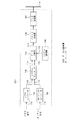
図1は本発明の実施の形態1によるデータ送信装置を説明するためのブロック図であり、図2は上記データ送信装置におけるパケット生成処理を説明するための模式図である。この実施の形態1のデータ送信装置1001は、ビデオ信号110を符号化してビデオエレメンタリーストリーム112を生成するビデオエンコーダ101と、オーディオ信号111を符号化してオーディオエレメンタリーストリーム114を生成するオーディオエンコーダ102と、ビデオエレメンタリーストリーム112及びオーディオエレメンタリーストリーム113をそれぞれ所要サイズのパックに対応するよう分割し、各パックに対応するビデオデータ及びオーディオデータをインターリーブして、MPEG2プログラムストリーム114を生成し、該プログラムストリーム114を出力するシステムエンコーダ(システムエンコード手段)103とを有している。
【0101】
また、上記データ送信装置1001は、上記プログラムストリーム114を制御信号116により指定されるサイズのパック(分割パック)に対応するよう分割するデータ分割器(分割手段)104と、各分割パック211,212・・・に送信用ヘッダ221,223,・・・を付加してパケット222,224,・・・生成するパケット生成器105と、これらのデータを各パケット単位で、アイソクロノス通信あるいはアシンクロノス通信によりネットワークNに出力するデータ送信器107と、上記データ分割器104を制御信号116により制御するシステム制御器106とを有している。ここで、上記データ送信器107は、従来の1394I/Fと同一構成となっている。
【0102】
次に動作について説明する。
本データ送信装置1001に入力されたビデオ信号110及びオーディオ信号111はそれぞれ、ビデオエンコーダ101及びオーディオエンコーダ102にて符号化され、ビデオエレメンタリーストリーム113及びオーディオエレメンタリーストリーム114として出力されてシステムエンコーダ103に入力される。
【0103】
上記システムエンコーダ103では、入力されたビデオエレメンタリーストリーム113及びオーディオエレメンタリーストリーム114はそれぞれ、所定サイズのパックに対応するよう分割され、さらに該パックに対応するビデオエレメンタリーストリームと、該パックに対応するオーディオエレメンタリーストリームとがインターリーブされて、MPEG2プログラムストリーム114とし出力される。
【0104】
なお、上記システムエンコーダ103における、各エレメンタリーストリーム112及び113の分割は、デコーダが上記MPEG2プログラムストリーム117をデコードする際に、限られたバッファ量でもってAV同期が正しく行われるよう、つまりオーディオデータとビデオデータとの間で正しく同期がとれるよう行われる。
【0105】
図2(a)は、システムエンコーダ103で生成されたMPEG2プログラムストリーム114の構成例を示している。図2(a)に示すように、一般にビデオデータのパック201,203、205,207,・・・、及びオーディオデータのパック202,204,206,208,・・・のサイズは可変長である。
【0106】
そして、システムエンコーダ103から出力されたMPEG2プログラムストリーム114がデータ分割器104に入力されると、上記データ分割器104では、プログラムストリーム114は、システム制御器106からの制御信号116により規定されるサイズの分割パックに対応するよう分割される。ここでは、プログラムストリーム114は、その先頭から等分割されるものとする。そして上記データ分割器104からは、図2(b)に示すように分割パック211,212,・・・が出力される。
【0107】
そして上記分割パックは、先頭のものから順にパケット生成器105に入力される。入力された分割パック211,212,・・・は、上記パケット生成器105にて、それぞれ送信用ヘッダ221,223,・・・が付加されて、パケット222,224,・・・が生成される。各パケットは、パケット生成器105からデータ送信器107に出力され、該データ送信器107から、上記各パケットはアイソクロノス通信あるいはアシンクロノス通信によりネットワークN上に出力される。
【0108】
このように本実施の形態1のデータ送信装置1001では、MPEG2プログラムストリーム114のデータをパケット化して出力するようにしたので、MPEG2プログラムストリーム114のデータを、従来の1394I/Fと同一構成のデータ送信器107における1サイクル期間のデータ伝送量でもって分割してネットワーク上に出力することができる。この結果、MPEG2システムエンコーダから出力されたMPEG2プログラムストリームのデータを、MPEG2トランスポートストリームに変換せずに、1394I/Fを用いて伝送することができる。
【0109】
また、このパケットを受信した機器では、上記パケットのデータを結合することにより、本データ送信装置にて生成されたMPEG2プログラムストリームを復元することが可能である。
【0110】
なお、上記実施の形態1では、図2に示すように、MPEG2プログラムストリームにおけるパックの分割方法として、該MPEG2プログラムストリームをその先頭から等分割する方法を示したが、上記データ分割器104におけるパックの分割方法としては、図3に示す分割方法を用いてもよい。
【0111】
つまり、上記実施の形態1と同様、MPEG2プログラムストリーム(図3(a)参照)を分割パックに分割する際に、図3(b)に示すように、該ストリームを構成するパックと、該分割パックの先頭を一致させるようにしてもよい。
【0112】
このようなストリームの分割方法は、データ分割器104がシステム制御器106からの指示を受けて行うこととなる。この場合、システムエンコーダ103はMPEG2プログラムストリーム114を出力する際、該ストリームを構成する各パックの先頭データが出力されたことを示す先頭位置信号115をデータ分割器114に出力する。これにより、データ分割器104では、システムエンコーダ103から出力されたプログラムストリームのパックの先頭が検知される。
【0113】
例えば、ビデオデータのパック201の大きさは、分割パックの大きさの整数倍ではないので、ビデオデータのパック201を分割して分割パックにする際には、該パック201に対応する最後の分割パック301のサイズが、通常の分割パックのサイズよりも小さくなる。上記パケット生成器105では、このような分割パック301に対しても、通常の大きさを有する分割パックと同様にヘッダ303を付加して、パケット304として出力する。
【0114】
また、オーディオデータのパック202の大きさも、分割パックの大きさの整数倍ではないので、このパック202に対する最後の分割パック305も、そのサイズが通常の分割パックのサイズよりも小さいものとなるが、この分割パック305も、上記データ送信器105にて上記分割パック301と同様にヘッダが付加されて、ネットワークN上に出力される。
【0115】
このようにMPEG2プログラムストリームを分割パックに分割する際に、該ストリームを構成するパックと、該分割パックの先頭を一致させるよう構成したデータ送信装置では、MPEG2プログラムストリームのデータをパケット化して1394I/Fを介してネットワークN上に出力することができる効果に加えて、1つのパケット内に、ビデオデータとオーディオデータが混在するのを回避することができる効果、さらに、通信エラーが発生してパケットが欠落した場合でも、欠落したパケットの次のパケットからデータの復号化を行うことができる効果がある。
【0116】
また、このデータ送信装置から出力されたパケットを受信した機器では、各パケットのデータを結合することにより、MPEG2プログラムストリームを復元することができる。
【0117】
また、データ分割器104におけるパックの分割方法としては、図2及び図3に示す方法以外に、図4のような方法も考えることができる。つまり、上記実施の形態1と同様、MPEG2プログラムストリーム(図4(a)参照)を分割パックに分割する際に、図4(b)に示すように、該ストリームを構成するパックと、該分割パックの先頭を一致させるとともに、全てのパケットを同一のサイズにそろえるようにしてもよい。
【0118】
例えば、ビデオデータのパック201の大きさは、分割パックの大きさの整数倍ではないので、ビデオデータのパック201を分割して分割パックにする際には、該パック201に対応する最後の分割パック301のサイズが、通常の分割パックのサイズよりも小さくなる。
【0119】
上記パケット生成器105では、このような分割パック301に対しては、スタッフィングデータ401を付加して通常の分割パックと同じ大きさにし、それにヘッダ403を付加し、パケット402として出力する。この際、ヘッダ403には、スタッフィングデータ401が付加されていることを示すデータまたはフラグを付加しておく。
【0120】
このようにMPEG2プログラムストリームを分割パックに分割する際に、該ストリームを構成するパックと、該分割パックの先頭を一致させ、しかも各パケットのサイズを同一サイズにそろえるよう構成したデータ送信装置では、MPEG2プログラムストリームのデータをパケット化して1394I/Fを介してネットワークN上に出力することができる効果、及び、1つのパケット内にビデオデータとオーディオデータが混在するのを回避できる効果等に加えて、パケットサイズが全てのパケットについて同一となるため、送信装置側でも受信装置側でもパケットデータを扱いやすくなる。特に受信装置では、パケットサイズを判定するための回路構成が不要となり、回路構成が簡単になる。
【0121】
また、このデータ送信装置から出力されたパケットを受信した機器では、各パケットのデータを結合するとともに、この際、通常サイズに比べて小さいパックに付加されているスタッフィングデータを取り除くことにより、送信側におけるMPEG2プログラムストリームを復元することができる。
【0122】
なお、実施の形態1におけるデータ送信装置においては、MPEG2プログラムストリームに含まれるデータとして、ビデオデータ及びオーディオデータを挙げたが、MPEG2プログラムストリームに含まれるデータはこれらに限るものではなく、上記ストリームは字幕データ等を含むものでもよい。
【0123】
また、実施の形態1のデータ送信装置では、MPEG2プログラムストリームのデータを等分割して分割パックを作成する場合について説明したが、上記プログラムストリームの分割は等分割でなくてもよく、そのサイズが、1394I/Fにて扱われるMPEG2トランスポートストリームのパケットサイズ程度に小さい分割パックが得られるものであれば、どのような分割方法でもよい。
【0124】
さらには、上記実施の形態1では、デジタルインターフェースとして1394I/Fを挙げたが、本発明は、1394I/Fだけでなく、MPEG2プログラムストリーム等のパックサイズに比べて極端に小さい(例えば1/10程度)サイズのパケットを単位としてデータ通信を行うインターフェースにも、1394I/Fと同様に適用可能である。
【0125】
以上のように、本実施の形態1のデータ送信装置では、MPEG2エンコーダにより出力されたMPEG2プログラムストリームのデータを、MPEG2トランスポートストリームのパケットサイズ程度に小さく分割するので、従来のMPEG2トランスポートストリームを扱うIEEE1394I/F等のディジタルインターフェースを介して、MPEG2プログラムストリームのデータを送信することができる。そして、受信側では、受信したパケットのデータを結合することにより、送信側のMPEG2プログラムストリームを復元することができる。
【0126】
実施の形態2.
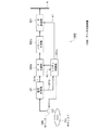
図5は本発明の実施の形態2によるデータ送信装置を説明するためのブロック図である。この実施の形態2のデータ送信装置1002は、記録媒体である光ディスク506からデータを読み出すための光ヘッド505と、読み出されたデータに対して復調処理及びECC復号処理を施す信号処理器501と、該信号処理器501からの、MPEG2プログラムストリームのデータ(PS形式のデータ)501aを、所定サイズの分割パックに対応するよう分割するデータ分割器502と、該分割パックに所定のヘッダを付加してパケットを生成するパケット生成器503と、該パケットをネットワークN上に出力するデータ送信器507とを有している。このデータ送信器507は従来の1394I/Fと同一構成となっている。
【0127】
また、上記データ送信装置1002は、上記信号処理器501から得られるディスク管理情報501bを受け、上記データ分割器502及び光ヘッド505を制御するシステム制御器504を有している。
【0128】
ここで、上記光ディスク506には、図6に示すようなデータ構造を有するデータが記録されているとする。ただし、実際の光ディスクに記録されているデータは、ECC符号化や変調処理が施されているため、上記データ送信装置1002における信号処理器501の出力データが、図6に示すデータ構造を有することとなる。
【0129】
図6は、DVD−Video規格のデータ構造の一部を模式的に示しており、DVD−Video規格では、一つのビデオタイトルセット(VTS)601は、VTSI602、VTSM_VOBS603、VTSTT_VOBS604、VTSI_BUP605から構成される。
【0130】
VTSI602はVTS601の管理情報であり、VTSI_BUP605はVTSI602の複製であり、そのバックアップ用データである。また、VTSM_VOBS603は、VTS601用のメニューデータである。そしてVTSTT_VOBS604がVTS601の映像、音声、字幕等のデータである。このVTSTT_VOBS604は、MPEG2プログラムストリームの構造を有している。
【0131】
このVTSTT_VOBS604の内容は、階層構造により記述することができ、図6では、パック(PCK)を単位とする階層構造を示している。パックはヘッダ等を含めて2048バイト(2kバイト)の大きさを有するデータ単位である。また、パックの大きさは、DVDディスクのセクタの大きさと同じである。パックはパック内に含むデータの種類によって分類することができる。パックの種類には、データ検索情報やハイライト情報が記述されているナビゲーションパック(NV_PCK)607、映像データを含むビデオパック(V_PCK)609、音声データを含むオーディオパック(A_PCK)608、字幕データ含むサブピクチャパック(SP_PCK)610がある。これらのパックは、ディスクに記録されている順序で復号化すれば、正しく同期した映像、音声等が得られるように多重化されている。
【0132】
次に、図5に示すデータ送信装置の動作について説明する。ここでは、上記光ディスク506には、ディスク管理情報や、図6に示すようなVTS601が記録されているとする。まず、光ディスク506に記録されているディスク管理情報が読み出される。この読み出されたディスク管理情報は、信号処理器501に入力され、復調及びECC復号処理等を施された後、システム制御器504に入力される。そしてシステム制御器504は、このディスク管理情報から、再生すべきVTS601が記録されている光ディスク上の位置情報を知る。そして、この制御器504がその位置情報を用いて光ヘッド505を制御することにより、光ディスク506からVTS601のデータがセクタ単位で順次読み出される。このVTS601のうち、VTSI602のような、VTS601内のデータの管理情報は、ディスク管理情報と同様の処理を施されて、システム制御器504に入力される。
【0133】
次に、VTSTT_VOBS604のような、VTS601内の映像や音声のデータを処理する場合について説明する。読み出されたデータは信号処理器501に入力される。信号処理器501では、復調、ECC復号処理等を施され、図6に示すパック列606が得られる。このパック列606は、データ分割器502に入力される。今、パック列606の先頭のパックであるNV_PCK607が入力された場合を考える。データ分割器502は、NV_PCK607が入力されると、システム制御器504により設定された大きさにNV_PCK607を分割する。
【0134】
図7は上記データ分割器502でのデータ分割方法の一例を説明するための図であり、1パックを8分割する場合を示している。具体的には、データ分割器502では、NV_PCK607は、256バイトのサイズを有する各分割パック701〜708に分割される。各分割パック701〜708は、順次データ送信器503に入力される。入力された分割パック701は、送信用のヘッダ709を付加された後、パケット710としてネットワークN上に出力される。なお、分割パック702〜708についても、分割パック701と同様に送信用のヘッダ709a,709b,・・・709gが付加された後、上記ネットワークN上に出力される。
【0135】
このようにしてNV_PCK607の送信が終わると、次にA_PCK608の送信が行われる。この場合における図5のデータ送信装置の動作は、NV_PCK607の送信の際の動作と同様である。そして、V_PCK609以降のデータも同様にして送信される。
【0136】
なお、上記実施の形態2では、データ分割器502におけるパックの分割方法としては、図7に示すように、2048バイトのパックを256バイトの分割パックに分割するものを示したが、分割方法はこれに限るものではなく、例えば、図8あるいは図9に示す分割方法も用いることができる。
【0137】
図8は、2048バイトのパックを160バイト毎に分割する例を示している。パック607の先頭から160バイト毎に分割すると、分割パック701a〜712aが得られ、また、パック607の残りのデータとパック608の先頭部のデータに対応する分割パック713aが得られる。これらの分割パック701a〜713aは、図7の分割パックの場合と同様に、データ送信器503によりヘッダが付加され、ネットワークN上に出力される。例えば、分割パック701aは、ヘッダ709dを付加されてパケット710aとなり、ネットワークN上に出力される。
【0138】
また、図9は、図8と同様に2048バイトのパックを160バイト毎に分割する方法を示している。ただし、図9に示す分割方法では、図8に示す分割方法とは異なり、2048バイトのパックをその先頭と160バイトの分割パックの先頭が必ず一致するよう分割している。
【0139】
2048バイトのパック607は、先頭から160バイト毎に分割されて分割パック701a〜712aが得られる。この場合、128バイトのデータがパック607の残りのデータ901となる。ここでは、残りデータ901を160バイトのデータとするために、残りデータ901に32バイトのスタッフィングデータ902を付加して、分割パック903とする。
【0140】
このように作成された分割パック701a〜712a、903は、図7に示す分割方法と同様に、データ送信器503によりヘッダが付加され、ネットワークN上に出力される。
【0141】
例えば、分割パック701aは、ヘッダ709dを付加されてパケット710aとなり、ネットワークN上に出力される。また、分割パック903は、ヘッダ709gが付加されてパケット904となり、ネットワークN上に出力される。
【0142】
以上のように、本実施の形態2によるデータ送信装置では、DVD等の記録媒体にセクタ等の単位で記録されたMPEG2プログラムストリーム形式のデータを、MPEG2トランスポートストリームのパケットサイズ程度に小さく分割するので、DVD等の記録媒体に記録されたデータを、従来のMPEG2トランスポートストリームを扱うIEEE1394I/F等のディジタルインターフェースを介して伝送することができる。
【0143】
ここで、図8及び図9に示すように、プログラムストリームのパックをその先頭が必ず分割パックの先頭となるように分割して送信することにより、受信側では、分割パックからプログラムストリームへの復元を容易に行うことが可能となるという効果が得られる。
【0144】
また、図8及び図9に示すように、プログラムストリームを任意のバイト数で分割することにより、ディジタルインターフェースの帯域を有効に利用することができるという効果が得られる。つまり、DVDに記録されたデータのアクセス速度は最大10.08Mbpsであるため、上記分割パックのサイズが160バイトである場合、1394I/Fでのアイソクロノス通信に必要な帯域は、10.24Mbps(=160バイト×8kHz)となり、DVDに記録されたデータのアクセスに1394I/Fの帯域を有効に利用できる。
【0145】
実施の形態3.
図10は本発明の実施の形態3によるデータ送信装置の構成を示すブロック図である。この実施の形態3のデータ送信装置1003は、記録媒体である光ディスク506からデータを読み出すための光ヘッド505と、読み出されたデータに対して復調処理及びECC復号処理を施す信号処理器501と、該信号処理器501からの、MPEG2プログラムストリームのデータ(PS形式のデータ)501aを、所定サイズの分割パックに対応するよう分割するデータ分割器502aと、該分割パックに所定のヘッダを付加してパケットを生成するパケット生成器503aと、該パケットのデータをネットワークN上に出力するデータ送信器507とを有している。ここでデータ送信器507は従来の1394I/Fと同一構成となっている。
【0146】
また、上記データ送信装置1003は、上記信号処理器501から得られるディスク管理情報501bを受け、上記データ分割器502a及び光ヘッド505を制御するシステム制御器504aを有している。
【0147】
そして、この実施の形態3では、上記データ分割器502aは、パックの先頭のデータを出力する際に、出力される分割パックがパックの先頭のデータを含んでいることを示す情報A1をシステム制御器504aに出力する構成となっている。また上記システム制御器504aは、上記パックの先頭のデータを含む分割パックが上記パケット生成器503aに出力されたときには、上記情報A1を該パケット生成器503aに出力する構成となっている。さらに、パケット生成器503aは、上記情報A1を受けたときには、分割パックに付加するヘッダ内に、該分割パックがパックの先頭データを含むことを示す情報を付け加える構成となっている。この実施の形態3のデータ送信装置におけるその他の構成は、上記実施の形態2と同一である。
【0148】
次に動作について説明する。
図6に示すデータ構造のデータが記録された光ディスク506からデータを読み出す場合について考える。まず、光ディスク506のディスク管理情報およびVTSI602のようなデータの管理情報を処理する手順は、実施の形態2で説明した手順と同様である。
【0149】
次に、VTSTT_VOBS604のような、VTS601内の映像や音声のデータを処理する場合について説明する。読み出されたデータは信号処理器501に入力される。該信号処理器501では、このデータに対する復調,ECC復号処理等により、図6に示すパック列606が得られる。そしてこのパック列606は、データ分割器502aに入力される。
【0150】
今、パック列606の先頭のパックであるNV_PCK607が入力された場合を考える。データ分割器502aは、NV_PCK607が入力されると、NV_PCK607を、システム制御器504により設定された大きさの分割パックに分割する。図11にはこの分割方法の一例として、上記パック607を8分割する方法が模式的に示されている。ここでは、NV_PCK607は、256バイトの大きさを有する分割パック701〜708に分割される。
【0151】
これらの分割パック701〜708は、順次データ分割器502aから出力される。データ分割器502aは、パックの先頭データを含む分割パックを出力するときに、出力される分割パックがパックの先頭データを含むことを示す情報A1をシステム制御器504aに通知する。このシステム制御器504aは、データ分割器502aから、パックの先頭データを含む分割パックが出力されたことを上記情報A1として、パケット生成器503aに知らせる。
【0152】
今、分割パック701がデータ分割器502aからパケット生成器503aに入力された場合を考える。分割パック701は、パック607の先頭データを含んでいるので、このことが情報A1としてデータ分割器502aからシステム制御器504aを介してパケット生成器503aに知らされる。このパケット生成器503aは、入力された分割パック701がパックの先頭データを含んでいることを知らされると、送信用ヘッダ1101を付加する際に、パックの先頭データを含んでいることを示す情報を該ヘッダ1101内に付け加え、図11に示すように、このヘッダ1101を分割パック701に付加して、パケット1102を生成し、データ送信器507に出力する。上記データ送信器507は、入力されたパケットをネットワークN上に出力する。
【0153】
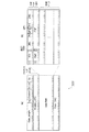
図12は、パケットがパックの先頭データを含んでいることを示す方法を説明するための図である。図12(a)には、IEEE1394のアイソクロノスパケット(アイソクロノス通信に用いられるパケット)の構造が示されており、横方向の列が32ビットのデータ列となっている。
【0154】
図12(b)はアイソクロノスパケットのData field部の構成を示している。このData field部は、分割パックのデータとそれに先立つCommon Isochronous Packet (CIP)ヘッダ1201とからなる。なお、分割パックのサイズは256バイトであるため、分割パックには64列のデータ列が対応することとなる。
【0155】
上記CIPヘッダ1201は、IEC61883規格により決められたヘッダである。CIPヘッダの第2クアドレット目(2列目)の先頭から9ビット目以降は、Format Dependent Field(FDF)であり、データの種類に依存するフィールドである。ここでは、FDFの先頭ビットをBOPビット1202として用いる。例えば、BOPビット1202は、この分割パックがパックの先頭データを含んでいるときに“1”、含んでいないときに“0”とすることにより、パケットがパックの先頭データを含んでいるか否かを示すことができる。また、上記アイソクロノスヘッダ1203とCIPヘッダ1201をあわせたものが、ヘッダ1101となる。
【0156】
次に、分割パック702が処理される。分割パック702は、パック607の先頭データを含んでいない。従って、パケット生成器503aは、分割パック702に送信用のヘッダ1103aを付加する際に、パックの先頭データを含んでいないことを示す情報をヘッダ1103a内に付け加える。そして、図11に示すように、このヘッダ1103aを分割パック702に付加してパケット1102を生成する。そしてデータ送信器507は該パケット1102をネットワークN上に出力する。以降、分割パック703〜708は、分割パック702と同様に処理される。
【0157】
このようにしてNV_PCK607の送信が終わると、次にA_PCK608の送信が行われる。この場合における図10に示すデータ送信装置1003の動作は、NV_PCK607の送信の際の動作と同様である。そして、V_PCK609以降のデータも同様にして送信される。
【0158】
以上のように、本実施の形態3のデータ送信装置1003では、DVD等の記録媒体にセクタ等の単位で記録されたMPEG2プログラムストリームのデータを、MPEG2トランスポートストリームのパケットサイズ程度に小さく分割するので、DVD等の記録媒体に記録されたデータを、従来のMPEG2トランスポートストリームを扱うIEEE1394等のディジタルインターフェースを通して伝送することができる。
【0159】
また、この際、パックの先頭データを含むパケットには、先頭データを含むことを示す情報を付加するので、受信側で分割パックからプログラムストリームを復元する処理が容易となるという効果が得られる。
【0160】
実施の形態4.
図13は本発明の実施の形態4によるデータ受信装置を説明するためのブロック図である。この実施の形態4のデータ受信装置1004は、上記実施の形態2のデータ送信装置1002からネットワークN上に出力されたパケットを受け取るデータ受信器1304と、該受信されたパケットのヘッダの解析を行ってその結果に応じて分割パックのデータ1301aを出力するとともに、分割パックのサイズデータ1301bを出力するヘッダ解析器1301とを有している。また上記データ受信装置1004は、分割パックを制御信号に基づいて結合してMPEG2プログラムストリームを構成する2048バイトのパックを生成するデータ結合器1302と、上記分割パックのサイズデータ1301bを上記制御信号として上記データ結合器1302に出力するシステム制御器1303とを有している。なお、図14は、この実施の形態4のデータ受信装置が受信するパケットの構成を模式的に示している。
【0161】
次に動作について説明する。
パケット710がネットワークN上からデータ受信器1304に受信されると、該データ受信器1304後段のヘッダ解析器1301は、該パケット710のヘッダ709を解析し、このパケット710がこのデータ受信装置1004宛のデータであるか否かを判断する。このパケット710がこのデータ受信装置1004宛のデータであれば、ヘッダ解析器1301は、パケット710からヘッダ709を取り除き、分割パック701をデータ結合器1302に対して出力する。また、ヘッダ解析器1301は、ヘッダ709に含まれている情報から、分割パックの大きさを示すサイズデータ1301bをシステム制御器1303に知らせる。また、上記システム制御器1303は、データ結合器1302に、分割パックの大きさを制御信号として知らせる。
【0162】
上記データ受信器1304及びヘッダ解析器1301は、以降のパケットについても、パケット710と同様の処理を行い、分割パック702〜708をデータ結合器1302に対して出力する。該データ結合器1302は、分割パック701〜708を受け取ると、システム制御器1303から知らされた分割パックの大きさに基づいて、分割パックを結合していく。ここでは、各分割パックの大きさは256バイトであるため、上記8つの分割パックを結合することにより、MPEG2プログラムストリームを構成する2048バイトのパックが作成される。そして、データ結合器1302からは、分割パック701〜708を結合してなる2048バイトのパック607のデータが出力される。
【0163】
このように本実施の形態4のデータ受信装置では、上記実施の形態2のデータ送信装置1002からネットワークN上に出力されたパケットを受信し、そのヘッダの解析結果に基づいて、該パケットに含まれる分割パックを結合するので、上記パケットのデータからDVD等の記録媒体から読み出されたMPEG2プログラムストリームを復元することができる。
【0164】
実施の形態5.
図15は本発明の実施の形態5によるデータ受信装置を説明するための図であり、該データ受信装置が受信するパケットの構成を模式的に示している。この実施の形態5のデータ受信装置は、実施の形態2のデータ送信装置から、図9に示すデータ形式で出力されたパケットを受信する構成となっており、実施の形態4のデータ受信装置1004と同様、データ受信器,ヘッダ解析器,データ結合器,システム制御器を有している。ただし、この実施の形態5では、データ結合器は、分割パック903における、スタッフィングのためのデータを除去する構成となっている。
【0165】
次に動作について説明する。
パケット710aがネットワークN上からデータ受信器1304に入力されると、その後段のヘッダ解析器1301は、パケット710aのヘッダ709dを解析し、パケット710aがこのデータ受信装置宛のデータか否かを判断する。パケット710aがこのデータ受信装置宛のデータであれば、ヘッダ解析器1301は、パケット710aからヘッダ709dを取り除き、分割パック701a(データ1301a)をデータ結合器1302に出力する。また、ヘッダ709dに含まれている情報から得られる分割パックの大きさ(データ1301b)をシステム制御器1303に知らせる。システム制御器1303は、データ結合器1302に、分割パックの大きさを知らせる。上記データ受信器1301及びヘッダ解析器1301は、以降のパケットについても、パケット710aと同様の操作を行い、分割パック702a〜712a、903をデータ結合器1302に出力する。
【0166】
データ結合器1302は、分割パック701a〜712a、903を受け取ると、システム制御器1303から知らされた分割パックの大きさに基づいて、分割パックを結合していく。ここでは、各分割パックの大きさは160バイトであり、分割パックを結合することにより2048バイトのパックを作る。
【0167】
この場合、データ結合器1302は、まず分割パック701a〜712aを結合して1920バイトのデータを得る。そして、分割パック903の先頭部128バイトのデータ901をさらに結合し、2048バイトのパック607を作成する。また、このとき、上記データ結合器1302は、分割パック903の残りのデータ902については、これがスタッフィングのためのデータであるので廃棄する。
【0168】
このようにして作成されたパック607はデータ結合器1302から出力される。同様にして、以降のパケットに対して処理を行うことにより、パックのデータを得ることができる。
【0169】
以上のように、実施の形態5のデータ受信装置では、上記実施の形態2のデータ送信装置1002から図9に示すデータ形式でネットワークN上に出力されたパケットを受信し、そのヘッダの解析結果に基づいて、該パケットに含まれる分割パックのデータを結合するとともに、スタッフィングのためのデータを廃棄するので、図9に示すデータ形式のパケットのデータを受信して、DVD等の記録媒体にセクタ等の単位で記録されたMPEG2プログラムストリームを復元することができる。
【0170】
実施の形態6.
図16(a)は、本発明の実施の形態6によるデータ記録装置を説明するためのブロック図である。この実施の形態6のデータ記録装置1006は、上記実施の形態4のデータ受信装置1004と同様、上記実施の形態2のデータ送信装置1002からネットワークN上に出力されたパケットを受け取るデータ受信器1304と、該受信されたパケットのヘッダの解析を行ってその結果に応じて分割パックのデータ1301aを出力するとともに、分割パックのサイズデータ1301bを出力するヘッダ解析器1301とを有している。また上記データ記録装置1006は、分割パックを制御信号に基づいて結合してMPEG2プログラムストリームを構成する2048バイトのパックを生成するデータ結合器1302と、上記分割パックのサイズデータ1301bを上記制御信号として上記データ結合器1302に出力するシステム制御器1604と、上記データ結合器1302の出力に対してECC符号化処理及び記録のための変調処理を施して記録用データを光ベッド1602へ出力する信号処理器1601とを有している。ここで、上記システム制御器1604は上記光ヘッド1602の制御をも行う構成となっている。なお、図14には、この実施の形態6のデータ記録装置1006が受信するパケットの構成を模式的に示されている。
【0171】
次に動作について説明する。
本実施の形態6のデータ記録装置1006では、上記ネットワークN上のパケットをデータ受信器1304にて受信し、該パケットのヘッダをヘッダ解析器1301にて解析し、データ結合器1302にてパックのデータを復元する動作は、上記実施の形態4のデータ受信装置1004と同様に行われる。
【0172】
上記データ結合器1302にて分割パック701〜708を結合して生成された2048バイトのパック607が、信号処理器1601に入力されると、この信号処理器1601は、上記パックに対してECCの付加,変調等の処理を行う。そして、システム制御器1604による光ヘッド1602の制御により、パック607は光ディスク1603上の記録位置に記録される。以降受信するパケットに関しても同様の処理が行われ、パケットからパックのデータを復元した後、順次光ディスク1603に記録されていく。
【0173】
以上のように、本実施の形態6のデータ記録装置1006では、上記実施の形態2のデータ送信装置1002から1394I/Fを介してネットワークN上に出力されたパケットを受信し、そのヘッダの解析結果に基づいて、該パケットに含まれる分割パックを結合し、該結合により得られるパックのデータを記録媒体上に記録するので、IEEE1394等のディジタルインターフェースを通して伝送されたパケットを受信して、MPEG2プログラムストリームのデータを復元し、これをセクタ等の単位でDVD等の記録媒体に記録することができる。
【0174】
なお、上記実施の形態6では、実施の形態2のデータ送信装置1002から1394I/Fを介してネットワーク上に送信されたパケットを受信して、MPEG2プログラムストリームを復元して記録する装置1006を示したが、該データ記録装置1006における信号処理器1601及び光ヘッド1602に替えて、AVデコーダ(映像音声復号化器)1605を備えることにより、図16(b)に示す、復元したプログラムストリームのデータを画像表示する装置1006aを実現することができる。
【0175】
なお、実施の形態2,3及び6のデータ送信装置及びデータ記録装置では、記録媒体として光ディスクを用いた例を示したが、これはセクタ等の単位でデータの記録再生をおこなうものであれば光ディスクでなくてもよい。セクタ等の単位でデータの記録再生を行うものの例としては、磁気ディスクがある。また、光ディスクに記録されているデータの形式は、図6に示すデータ形式に限定されるものではない。
【0176】
また、実施の形態2ないし6のデータ送信装置、データ受信装置、データ記録装置の実施例においては、プログラムストリームのパックの大きさが2048バイトである場合について説明したが、上記パックの大きさはこれに限るものではない。
【0177】
また、実施の形態2および3のデータ送信装置では、2048バイトのパックのデータを等分割して分割パックを作成する場合について説明したが、該パックのデータの分割は等分割でなくてもよい。
【0178】
また、実施の形態2および3のデータ送信装置では、分割パックがプログラムストリームのパックの先頭データを含んでいるか否かをヘッダ中のフラグで示す場合について説明したが、これは異なる方法によって示してもよい。例えば、分割パック数のカウント値をヘッダ中に設け、このカウンタ値によって、分割パックがプログラムストリームのパックの先頭データを含んでいることを示す方法がある。
【0179】
また、実施の形態2および3のデータ送信装置では、分割パックがパックの先頭データを含んでいることは、システム制御器504を介してデータ送信器503に通知したが、これはシステム制御器504を介さず、データ分割器502からデータ送信器503に直接通知してもよい。
【0180】
実施の形態7.
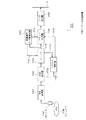
図17は、本発明の実施の形態7によるデータ送信装置を説明するためのブロック図である。この実施の形態7のデータ送信装置1007は、記録媒体である光ディスク1708からデータを読み出すための光ヘッド1707と、読み出されたデータに対して2値化処理及び復調処理等を施す信号処理器1701と、該信号処理器1701の出力に対してECC復号処理を施すECC復号器1702とを有している。
【0181】
また、上記データ送信装置1007は、ECC復号器1702から出力されるデータを蓄積するバッファ1703と、該バッファ1703から出力されたデータとクロック情報をパケット化し、得られたパケットに、1394I/F等のディジタルインターフェースを介してデータを伝送するためのヘッダ情報等を付加するパケット生成器1704と、該パケット生成器1704から出力されるパケットをネットワークN上に出力するデータ送信器1709とを有している。ここで、データ送信器1709は従来の1394I/Fと同一構成となっている。
【0182】
また、上記データ伝送装置1007は、上記バッファ1703に対してデータの要求を行い、これに応じてバッファ1703から出力されるデータを復号化する映像音声データ復号化器1706と、上記バッファでのデータ蓄積量に基づいて上記パケット生成器1704を制御するシステム制御器1705を有している。
【0183】
次に動作について説明する。
光ディスク1708から光ヘッド1707により読み出されたデータは、信号処理器1701にて2値化及び復調等の処理が施されて、ECC復号器1702に入力される。ECC復号器1702に入力されたデータは、ECC復号処理を施されてバッファ1703に入力される。
【0184】
ここで、上述したデータの読み出し動作、つまり光ディスク1708からデータを読み出してバッファ1703に入力するまでの動作が行われるか否かは、バッファ1703のデータ蓄積量によって決まる。
【0185】
すなわち、バッファ1703のデータ蓄積量が第1の所定量よりも少なくなると、光ディスク1708から連続的にデータが読み出されてバッファ1703に蓄積される。また、バッファ1703のデータ蓄積量が第2の所定量を超えると、光ディスク1708からのデータの読み出しは停止される。
【0186】
また、上記バッファ1703から映像音声データ復号化器1706へのデータの読み出しは、映像音声復号化器1706からのバッファ1703に対するデータ転送要求1710により行われる。バッファ1703は、データ転送要求を受けると、入力された順にデータを出力していく。出力されたデータ1714は、映像音声データ復号化器1706により順に復号化されていく。またバッファ1703から出力されたデータ1714は、同時にパケット生成器1704にも入力される。また、上記パケット生成器1704には、映像音声データ復号化器1706にて生成されるクロック情報1711が入力される。
【0187】
そして上記パケット生成器1704は、バッファ1703からのデータとクロック情報をパケット化し、生成されたパケットに、ディジタルインターフェース上でデータを伝送するためのヘッダ情報等を付加してデータ送信器1709に出力する。データ送信器1709はパケット生成器1704から入力されたパケットをネットワークN上に出力する。
【0188】
以下、図18に示すタイミングチャートを用いて詳細な動作について説明する。図18(a)は、バッファ1703のデータ蓄積量の時間変化をグラフで示し、図18(b)はバッファ1703がアンダーフロー状態であるか否かを、“H”レベルと“L”レベルにより示している。つまり、Hレベルの期間は、上記バッファ1703がアンダーフロー状態であることを示し、Lレベルの期間は、上記バッファ1703がアンダーフロー状態でないことを示す。
【0189】
また、図18(c)は、映像音声データ復号化器1706からバッファ1703へのデータ転送要求を示すものであり、Hレベルの期間に転送要求を行っている。図18(d)は、バッファ1703からデータが出力される期間を示し、Hレベルの期間がデータの出力期間である。図18(e)はデータ送信器からネットワークN上に出力されたデータを示している。
【0190】
時刻t0において、バッファ1703には、第2の所定量と同じ量のデータが蓄積されている。そして時刻t1において、映像音声データ復号化器1706からのデータ転送要求が行われる。ここでは、映像音声データ復号化器1706からバッファ1703へのデータ転送要求の開始は、等時間間隔で行われるものとしている。映像音声データ復号化器1706からバッファ1703へのデータ転送要求が行われると、バッファ1703から映像音声データ復号化器1706及びパケット生成器1704へデータ1801を出力するデータ出力動作が開始される。時刻t2において、データ転送要求が停止すると、バッファ1703からのデータ転送は一時停止する。
【0191】
ここでは、データ送信器1709は、IEEE1394I/Fであるため、データ送信器1709では、時刻t3において、サイクルスタートパケット1803が検出されて、サイクル1804が開始される。時刻t3において、既にバッファ1703から出力されたデータであってネットワークN上に出力されていないデータは、データ1801であるので、上記パケット生成器1704では、このデータ1801に、上記データ送信器器1709を介して伝送するためのヘッダ等1802を付加し、該データ送信器1709に出力する。
【0192】
図19は、IEEE1394I/Fで扱うアイソクロノスパケットの構成を示す。アイソクロノスパケット1800は、映像音声データ1904に、アイソクロノスヘッダ1902とCIPヘッダ1903とを付加したものである。ここでは、映像音声データ1904は、データ1801である。また、CIPヘッダ1903にはバッファフラグ1905が含まれており、このフラグ1905によって、バッファ1703がアンダーフローを起こしているか否かが示されている。
【0193】
ここでは、バッファ1703がアンダーフローしている場合を“1”で表し、アンダーフローしていない場合を“0”で表すことにする。したがって、ヘッダ1802のCIPヘッダでは、バッファフラグ1905は“0”である。以降、同様にバッファから出力されたデータをディジタルインターフェースとしてのデータ送信器1709に出力していく。
【0194】
時刻t4で、バッファ1703のデータ蓄積量が第1の所定量よりも小さくなる。バッファ1703のデータ蓄積量は、これを示す情報1715によりシステム制御器1705が監視している。システム制御器1705は、バッファ1703のデータ蓄積量が第1の所定量よりも小さくなったことを検出すると、光ディスク1708からのデータの読み出し動作が行われるよう光ヘッド1707,信号処理器1701及びECC復号器1702を制御する。そして、時刻t5にバッファ1703のデータ蓄積量が第2の所定量に達すると、上記システム制御器1705は、光ディスク1708からのデータの読み出し動作が停止されるよう、光ヘッド1707,信号処理器1701及びECC復号器1702を制御する。
【0195】
今、バッファ1703のデータ蓄積量が第1の所定量よりも小さくなったにもかかわらず、データがバッファ1703に入力されない場合を考える。この時刻をt6とする。例えば、再生すべきデータにアクセスする際に、トラックジャンプ等に失敗してデータが記録されているセクタを見つけるのに非常に長い時間がかかった場合に、このような状態が生じる。また、ECC復号器1702でECCエラーが発生し、同じデータをもう一度光ディスク1708から読み出すような場合にも、このような状態が生じる。
【0196】
時刻t7になると、映像音声データ復号化器1706からのデータ転送要求が行われ、バッファ1703からのデータ出力が行われると、時刻t8に、バッファ1703のデータ蓄積量が0となり、アンダーフローを起こす。システム制御器1705は、バッファ1703がアンダーフロー状態であることを検出すると、パケット生成器1704に、信号1713によりバッファ1703がアンダーフロー状態であることを知らせる。
【0197】
時刻t9に、映像音声データ復号化器1706からバッファ1703へのデータ転送要求が行われるが、バッファ1703はアンダーフロー状態であるので、バッファ1703からはデータは出力されない。なお、このとき何らかのデータがバッファから出力されたとしても、出力されたデータは有効なデータではない。
【0198】
時刻t10には、サイクルスタートパケット1805が検出されて、サイクル1806が開始されるが、時刻t10において、バッファ1703から出力されたデータであってデータ送信器1709に出力されていないデータは、データ1807であるので、該データ送信器1709では、このデータ1807に、ヘッダ等1808を付加してネットワークN上に出力する。
【0199】
時刻t11にてサイクルスタートパケット1809が検出されて、サイクル1810が開始される。時刻t10においては、バッファ1703から出力されたデータであってデータ送信器1709を介してネットワークN上に出力されていないデータはなく、しかもバッファ1703はアンダーフロー状態である。そのため、パケット生成器1704は、ヘッダのみをアイソクロノスパケット1811としてデータ送信器1709に送出し、データ送信器1709からはヘッダのみからなるアイソクロノスパケット1811がネットワークN上に出力される。
【0200】
図20は、このアイソクロノスパケット1811の構成を示している。図20に示すように、アイソクロノスパケット1811に相当するアイソクロノスパケット2011には、データ部がない。また、バッファ1703がアンダーフローの状態であるので、バッファフラグ2205は“1”となっている。
【0201】
サイクル1812においても、サイクル1810と同じく、バッファ1703から出力されたデータであってネットワークN上に出力されていないデータはなく、かつバッファ1703はアンダーフロー状態であるので、アイソクロノスパケット1811と同様なアイソクロノスパケット1813を出力する。
【0202】
時刻t12になると、バッファ1703へのデータの入力が再開される。これにより、バッファ1703のアンダーフロー状態は解除される。時刻t13にサイクルスタートパケットが検出されて、サイクル1814が開始される。この時刻t13において、バッファ1703から出力されたデータであってディジタルインターフェース1709に出力されていないデータはないが、バッファ1703はアンダーフロー状態でない。そのため、パケット生成器1704で生成されたヘッダのみのアイソクロノスパケット1815は、データ送信器1707を介してネットワークN上に出力される。このときバッファ1703はアンダーフロー状態ではないので、アイソクロノスパケット1815のバッファフラグの値は、アイソクロノスパケット1811のバッファフラグ1905と同様“0”となる。
【0203】
時刻t14には、バッファ1703のデータ蓄積量が第2の所定量に達し、バッファ1703からのデータの出力が再開される。以降、サイクル1804と同様にデータの伝送が行われる。
【0204】
このように本実施の形態7のデータ送信装置1007では、バッファ1703がアンダーフローを起こしてデータを送信できない場合に、バッファのアンダーフローが生じたことを示す情報をパケット内のヘッダ情報に入れて送信するので、バッファのアンダーフローが生じたことを受信側で検知することができる。これにより受信側では動作モードをエラー処理モード等に移行して対応することが可能となる。
【0205】
実施の形態8.
図21〜図23は、本発明の実施の形態8によるデータ伝送装置を説明するための図である。この実施の形態8のデータ送信装置では、バッファ1703がアンダーフローを起こしていないときのデータ出力動作、つまり光ディスク1708からデータを読み出してデータ送信器1709がネットワークN上にパケットを出力する動作は、図17に示す実施の形態7のデータ送信装置1007と同様に行われる。
【0206】
図21(a)は、本実施の形態のデータ送信装置のバッファ1703からのデータ出力の様子を示し、図21(b)は、ネットワークN上での出力データの様子を示しており、図21(a),図21(b)は、それぞれ上記実施の形態7のデータ伝送装置の動作を説明する図18(d),図18(e)に対応するものである。
【0207】
また、図22は、本実施の形態8のデータ伝送装置で扱われるアイソクロノスパケット2200の構造を示しており、この図22からわかるように、上記アイソクロノスパケット2200では、CIPヘッダ2201の構造が、上記実施の形態7のデータ伝送装置で扱われるアイソクロノスパケットのCIPヘッダ1903とは異なり、CIPヘッダ1903からバッファフラグ1905を除いた構造となっている。なお、上記図21におけるサイクル2104及び2106のアイソクロノスパケット2101,2107は上記アイソクロノスパケット2200と同一構成となっている。
【0208】
次に動作について説明する。
なお、図18に示す時刻t0〜t6までの動作は、実施の形態7のものと同一であるので、時刻t6以降の動作について説明する。今、バッファ1703のデータ蓄積量が第1の所定量よりも小さくなったにもかかわらず、データがバッファ1703に入力されない状態を考える。時刻t6では、本実施の形態8のデータ送信装置はこのような状態となっている。
【0209】
図18に示すように、時刻t7では、映像音声データ復号化器1706からのデータ転送要求が行われ、バッファ1703からのデータ出力が行われるが、時刻t8に、バッファ1703のデータ蓄積量が0となり、バッファ1703はアンダーフロー状態となる。システム制御器1705は、バッファ1703がアンダーフロー状態であることを検出すると、所定の信号1713によりパケット生成器1704に、バッファ1703がアンダーフロー状態であることを知らせる。
【0210】
時刻t9に、映像音声データ復号化器1706からバッファ1703へのデータ転送要求が行われるが、バッファ1703はアンダーフロー状態であるので、有効なデータは出力されない。
【0211】
図21に示すように、時刻t10に、サイクルスタートパケット2105が検出されて、サイクル2106が開始される。時刻t10において、バッファ1703から出力されたデータであってネットワークN上に出力されていないデータは、データ2107であるので、パケット生成器は、このデータ2107に伝送用のヘッダ等2108を付加してパケットを生成し、データ送信器1709は該生成されたパケットをネットワークN上に出力する。
【0212】
時刻t11にサイクルスタートパケット2109が検出されて、サイクル2110が開始される。時刻t10において、バッファ1703から出力されたデータであってネットワークN上に出力されていないデータはなく、しかもバッファ1703はアンダーフロー状態である。
【0213】
ここでパケット生成器1704は、図22に示すように、アイソクロノスパケット1900(図19(a)参照)の映像音声データ1904に代えて、あらかじめ定めておいたバッファのアンダーフローが生じたことを示す特定のパターンのデータ2204aを含むアイソクロノスパケット2200を生成する。なおバッファのアンダーフローが生じたことを示す特定のパターンとしては、図22に示すアイソクロノスパケットの横一列のすべてのビット(32ビット)が0であるデータや、MPEG2で定められている32ビットのシーケンスエラーコード000001B4h(hは16進数であることを示す)などを用いることができる。そして、このパケットをアイソクロノスパケット2113としてデータ送信器1709に出力すると、データ送信器1709からは上記アイソクロノスパケット2113がネットワークN上に出力される。
【0214】
サイクル2112においても、サイクル2110と同じく、バッファ1703から出力されたデータであってネットワークN上に出力されていないデータはなく、しかもバッファ1703はアンダーフロー状態であるので、パケット生成器1704は、アイソクロノスパケット2113と同様に、映像音声データ1904に代えて上記特定のパターンのデータ2204aを含むアイソクロノスパケット2114を生成してデータ送信器1709に出力する。これによりデータ送信器1709からは、アイソクロノスパケット2114がネットワークN上に出力される。
【0215】
図18に示すように、時刻t12になると、バッファ1703へのデータの入力が再開される。これにより、バッファ1703のアンダーフロー状態は解除される。図21に示すように、時刻t13にサイクルスタートパケットが検出されて、サイクル2117が開始される。時刻t13において、バッファ1703から出力されたデータであってデータ送信器1709に出力されていないデータはないが、バッファ1703はアンダーフロー状態でない。そのため、パケット生成器1704は、ヘッダのみからなるアイソクロノスパケット2105をデータ送信器1707に出力する。このときバッファ1703はアンダーフロー状態ではないので、アイソクロノスパケット2115は、図23に示すようにアイソクロノスヘッダ2302とCIPヘッダ2301とDataCRCのみからなるアイソクロノスパケット2301と同一の構成となる。
【0216】
図18に示すように、時刻t14には、バッファ1703のデータ蓄積量が第2の所定量に達し、バッファ1703からのデータの出力が再開される。以降、サイクル2104と同様にデータの伝送が行われる。
【0217】
このように本実施の形態8のデータ送信装置では、バッファがアンダーフローを起こしてデータが送信できない場合に、バッファのアンダーフローが生じたことを示す情報として、所定の特定パターンのデータをパケット内のデータ部に入れて送信するので、上記実施の形態7と同様、バッファのアンダーフローが生じたことを受信側に知らせることができるという効果が得られる。
【0218】
実施の形態9.
図24は本発明の実施の形態9によるデータ受信装置を説明するためのブロック図である。本実施の形態9のデータ受信装置1009は、実施の形態7のデータ送信装置1007からネットワークN上に出力されたパケットを受信する構成となっており、上記ネットワークN上のパケットを受信するデータ受信器2407と、受信したパケットのヘッダの解析を行って、送信装置のバッファ出力に相当するデータ2401aを出力するとともに、ヘッダ解析結果2401bを出力するヘッダ解析器2401と、上記ヘッダ解析器2401からのデータ2401aに対して復号化処理を施して映像音声信号を出力する映像音声データ復号化器2402と、上記ヘッダ解析結果2401bに基づいて上記復号化器2402を制御するシステム制御器2403とを有している。
【0219】
次に動作について説明する。
データ受信器2407がネットワークN上のパケットを受け取ると、その後段のヘッダ解析器2401はヘッダのチェックを行う。具体的には、パケット1800等のパケット、すなわち図19に示す構成のパケットを受信した場合、まずアイソクロノスヘッダ1902のチェックを行い、CIPヘッダ1903のチェックを行う。CIPヘッダ1903のチェックの際には、CIPヘッダ1903に含まれるバッファフラグ1905を検査する。バッファフラグが「バッファのアンダーフローなし」を示している場合、映像音声データ1904のCRC(cyclic redundancy check )チェック, いわゆる巡回冗長検査を行う。CRCが正しい場合には、パケット内の映像音声データ1904を映像音声データ復号化器2402に出力する。映像音声データ復号化器2402は受信した映像音声データを復号化し、映像音声信号を出力する。
【0220】
次に、CIPヘッダ1901に含まれるバッファフラグ1905を検査した際に、バッファフラグが「バッファのアンダーフロー有り」を示している場合について説明する。この場合のデータ受信装置の動作は、図18のパケット1811、すなわち図20に示す構成のパケット2011を受信した場合の動作となる。
【0221】
この際、ヘッダ解析器2401は、システム制御器2403に、送信側でバッファのアンダーフローがあったことをヘッダ解析結果2401bにより通知する。これによりシステム制御器2403が送信側でのバッファのアンダーフローがあることを知ると、該制御器2403は、このことを映像音声データ復号化器2402に知らせる。これにより、映像音声データ復号化器2402は、通常の復号化処理モードでの動作を停止し、エラー処理モードの動作を行う。エラー処理モードの動作としては、直前の映像をスチルして表示する、音声信号をミュートする、等がある。
【0222】
次に、データ受信器2407は、パケット1813を受信し、このパケットがヘッダ解析器2401に入力される。このパケット1813のCIPヘッダに含まれるバッファフラグ1905は、「バッファのアンダーフロー有り」を示している。したがって、ヘッダ解析器2401は、ヘッダ解析結果2401bとして、システム制御器2403に対して、送信側でバッファのアンダーフローがあったことを通知する。これによりシステム制御器2403が送信側でのバッファのアンダーフローがあることを知ると、このことを映像音声データ復号化器2402に知らせる。すると、映像音声データ復号化器2402は、すでにエラー処理モードの動作を行っているため、このエラー処理モードの動作を続行する。
【0223】
次に、データ受信器2407がパケット1815を受信し、このパケットがヘッダ解析器2104に入力される。このパケット1815のCIPヘッダに含まれるバッファフラグ1905は、「バッファのアンダーフロー無し」を示している。したがって、ヘッダ解析器2401は、ヘッダ解析結果2405として、システム制御器2403に、送信側でバッファのアンダーフローがなくなったことを通知する。これによりシステム制御器2403は、送信側でのバッファのアンダーフロー状態が解消されたことを知ると、このことを映像音声データ復号化器2402に知らせる。すると、映像音声データ復号化器2402は、エラー処理モードの動作を停止し、通常の復号化モードの動作を再開する。
【0224】
このように実施の形態9のデータ受信装置1009では、ディジタルインターフェースを介して受信したパケットに、送信側でバッファのアンダーフローが生じたことを示す情報がある場合に、バッファのアンダーフローが生じたことを検知し、映像音声データの復号化処理における動作モードを通常の動作モードからエラー処理モードに移行するので、受信側では、迅速なエラー処理を行うことができ、送信側でのバッファのアンダーフローによる映像や音声信号の乱れを効果的に抑えることができるという効果が得られる。
【0225】
実施の形態10.
次に本発明の実施の形態10によるデータ受信装置を図24、図18、図21、図22を用いて説明する。この実施の形態10のデータ受信装置は、本発明の実施の形態8のデータ送信装置からネットワークN上に出力された、図21(b)に示すパケット列を受信する構成となっている。この実施の形態10のデータ受信装置は、上記実施の形態9のデータ受信装置とは、ヘッダ解析器での、アンダーフローがあったことを示すデータの判定処理のみ異なっている。
【0226】
次に動作について説明する。
データ受信器2407がパケットを受け取ると、その後段のヘッダ解析器2407では、ヘッダのチェックを行う。パケット2102等のパケット、すなわち図22の構成のパケット2200を受信した場合、まずアイソクロノスヘッダ1902のチェックを行い、CIPヘッダ2201のチェックを行う。そして映像音声データ1904のCRCチェックを行う。CRCが正しい場合には、映像音声データ1904が所定の特定パターンを含むか否かをチェックする。所定のパターンとしては、32ビットすべてのビットが0であるデータや、MPEG2で定められている32ビットのシーケンスエラーコード000001B4h(hは16進数であることを示す)などである。
【0227】
映像音声データ1904が所定の特定パターンを含まない場合には、ヘッダ解析器2401は映像音声データ1904を映像音声データ復号化器2402に出力する。映像音声データ復号化器2402は受信した映像音声データを復号化し、映像音声信号を出力する。
【0228】
一方、上記映像音声データ2204が所定の特定パターンを含む場合について説明する。これは図21に示すパケット2103を受信した場合に相当する。このパケット2103の構造は、図22に示すアイソクロノス通信パケット2200と同一である。このようにパケット2200の映像音声データ2204に所定の特定パターン2204aが含まれている場合は、送信側でバッファのアンダーフローが起こったことを示している。この際、データ受信器2401は、ヘッダ解析結果2405として、システム制御器2403に、送信側でバッファのアンダーフローがあったことを通知する。システム制御器2403は、送信側でのバッファのアンダーフローがあったことを知ると、それを映像音声データ復号化器2402に知らせる。これにより、映像音声データ復号化器2402は、通常の復号化処理モードの動作を停止し、エラー処理モードの動作を開始する。エラー処理モードの動作の例としては、直前の映像をスチルして表示する、音声信号をミュートする、等がある。
【0229】
次に、データ受信器2401は、パケット2114を受信する。パケット2114の映像音声データは所定の特定パターンを含むものであり、送信側でバッファのアンダーフローが起こったことを示している。したがって、データ受信器2401は、ヘッダ解析結果2405として、システム制御器2403に、送信側でバッファのアンダーフローがあったことを通知する。システム制御器2403は、送信側でのバッファのアンダーフローがあることを知ると、それを映像音声データ復号化器2402に知らせる。映像音声データ復号化器2402は、すでにエラー処理モードの動作を行っているたため、エラー処理モードの動作を続行する。
【0230】
次に、データ受信器2401は、パケット2115を受信する。パケット2115は、図23に示すアイソクロノスパケット2301と同一構成となっており、映像音声データを含んでおらず、送信側でバッファのアンダーフローが起こっていないことを示している。したがって、データ受信器2401は、ヘッダ解析結果2405として、システム制御器2403に、送信側でバッファのアンダーフローが解消されたことを通知する。システム制御器2403は、送信側でのバッファのアンダーフロー状態が解消されたことを知ると、それを映像音声データ復号化器2402に知らせる。映像音声データ復号化器2402は、エラー処理モードの動作を停止し、通常の復号化モードの動作を開始する。
【0231】
このように実施の形態10のデータ受信装置では、データ送信器(ディジタルインターフェース)を介して受信したパケットに、送信側でバッファのアンダーフローが生じたことを示す情報として特定パターンデータがある場合に、バッファのアンダーフローが生じたことを検知し、映像音声データの復号化処理をエラー処理モードに移行するので、上記実施の形態9と同様、復号化側で迅速なエラー処理を行うことができ、送信側でのバッファのアンダーフローによる映像や音声信号の乱れを最小限に押さえることができるという効果が得られる。
【0232】
なお、実施の形態7から10の実施の形態では、ディジタルインターフェースとしてIEEE1394を例に挙げて説明したが、これは他のディジタルインターフェースでもよい。また、実施の形態7から10の実施の形態では、記録媒体に記録されているデータを映像音声データとしたが、これは字幕データ等を含んでいてもよい。また、映像データのみ、または音声データのみであってもよい。また、実施の形態7および8のデータ送信装置では、記録媒体として光ディスクを例に挙げて説明したが、これは磁気ディスク等の他の記録媒体であってもよい。
【0233】
また、本発明の実施の形態7および9では、バッファフラグ1905は、バッファのアンダーフローが発生したことを示すのに“1”、バッファのアンダーフローが発生していないことを示すのに“0”を用いるとしたが、これは逆でもよい。
【0234】
また、本発明の実施の形態7および8では、バッファ出力をそのままパケット生成器に出力する構成を示したが、バッファ出力を、実施の形態2に示すように分割してパケット生成器に出力するようにしてもよい。また、図18に示す映像音声復号化器1706からのデータ転送要求と、アイソクロノスサイクルとの時間関係は、図18に示すものに限らない。
【0235】
実施の形態11.
図25は本発明の実施の形態11によるデータ送信装置を説明するためのブロック図である。この実施の形態11のデータ送信装置1011は、記録媒体である光ディスク2508からデータを読み出すための光ヘッド2507と、読み出されたデータに対して2値化処理及び復調処理等を施す信号処理器2501と、該信号処理器2501の出力に対してECC復号処理を施すECC復号器2502とを有している。このデータ送信装置1011では、光ディスク2508から信号処理器2501へのデータの読み出しは、ECC処理の単位毎に行われるようになっている。
【0236】
また、上記データ送信装置1011は、ECC復号器2502から出力されるデータを蓄積するバッファ2503と、該バッファ2503から出力されたデータとクロック情報をパケット化し、さらに1394I/F等のディジタルインターフェースを介してデータを伝送するためのヘッダ情報等を付加するパケット生成器2504と、該パケット生成器2504から出力されるパケットをネットワークN上に出力するデータ送信器2507とを有している。ここで、データ送信器2507は従来の1394I/Fと同一構成となっている。
【0237】
また、上記データ伝送装置1011は、上記バッファ2503に対してデータの要求を行い、これに応じてバッファ2503から出力されるデータを復号化するととにも、上記クロック情報を出力する映像音声データ復号化器2506と、上記バッファでのデータ蓄積量に基づいて上記パケット生成器2504を制御するシステム制御器2505を有している。
【0238】
また、図26(a)は、記録媒体である光ディスク2508のセクタ構造を説明するための図であり、円盤形状の光ディスク2508に形成されたトラックを直線状に展開して示している。
【0239】
図26(a)には、セクタサイズがユーザデータサイズとして2kバイト(2048バイト)あり、ECC処理の単位が16セクタ(ユーザデータサイズは32kバイト)であることが示されている。以下では、このECCの1ブロックの単位をクラスタと呼ぶ。光ディスク2508上の1セクタに実際に記録されているデータは、2kバイトのユーザデータにECCデータが付加されたサイズを有している。
【0240】
次に動作について説明する。
光ディスク2508からのデータの読み出しはクラスタを単位として行われる。光ディスク2508から読み出されたデータは、信号処理器2501で2値化、復調等の処理を施された後、ECC復号器2502に入力される。ECC復号器2502に入力されたデータは、ECC復号処理を施され、バッファ2503に入力される。
【0241】
上記データ読み出し動作、つまりデータが光ディスク2508から読み出されてバッファ2503に入力されるまでの動作は、バッファ2503のデータ蓄積量によって間欠的に行われる。すなわち、バッファ2503のデータ蓄積量が第1の所定量よりも少なくなると、光ディスク2508から連続的にデータが読み出されてバッファ2503に蓄積される。また、バッファ2503のデータ蓄積量が第2の所定量を超えると、光ディスク2508からのデータの読み出しは停止される。
【0242】
バッファ2503から映像音声データ復号化器2506へのデータの読み出しは、映像音声復号化器2506からの要求2510により行われる。バッファ2503は、データ読み出しの要求を受けると、入力された順にデータを出力していく。出力されたデータ2514は、映像音声データ復号化器2506により順に復号化されていく。バッファ2503から出力されたデータ2514は、同時にパケット生成器2504にも入力される。また、パケット生成器2504には、映像音声データ復号化器2506で生成されたクロック情報2511が入力される。このパケット生成器2504は、データとクロック情報をパケット化し、得られたパケットにヘッダ情報等を付加してデータ送信器2507に出力する。するとデータ送信器2507からは、パケットがネットワークN上に出力される。
【0243】
以下上記動作について詳述する。光ディスク2508から読み出されたクラスタ2617のデータ(図26(a)参照)が、信号処理器2501で処理を施された後、ECC復号器2502にてエラーが発生することなくECC復号されたとする。この場合は、ECC復号処理が施されたクラスタ2617のデータは、映像音声データ復号化器2506への読み込みと共に、バッファ2503に入力される。そして、バッファ2503から出力されたクラスタ2617のデータは、パケット生成器2504にてパケット化されてデータ送信器2507を介して、ネットワークN上に出力される。
【0244】
図26(a)に示すように、クラスタ2617は、2048バイトの大きさを有するセクタ2601〜2616から構成されているため、パケット生成器2504は、取得した帯域内でデータ送信器2507を介して伝送できるようにクラスタ2617のデータを分割し、分割したクラスタのデータにヘッダ情報等を付加してパケット化し、得られたパケットをデータ送信器2507に出力する。
【0245】
図27はIEEE1394I/Fにて扱われるアイソクロノスパケットの構成を示す。アイソクロノスパケット2700は、映像音声データ2704に、アイソクロノスヘッダ2703とCIPヘッダ2701とを付加したものである。ここでは、映像音声データ2704が、クラスタ2617のデータとなる。
【0246】
図28は、ネットワークN上に流れるアイソクロノスデータを示す。サイクル2805,2806では、クラスタ2617のデータ2801、2802が流れており、サイクル2806のデータ2802がクラスタ2617の最後のデータとなっている。
【0247】
次に、光ディスク2507から読み出されたクラスタ2618のデータ(図26(a)参照)をECC復号器2502にてECC復号化したときに、ECCエラーが発生したとする。この場合、ECC復号化器2502は、ECCエラーが発生したことを信号2512によりシステム制御器2505に通知する。ここでは、ECCエラーが発生したクラスタ2618をもう一度光ディスク2508から読み出すことは行われず、次のクラスタ2619の読み出しが行われる。
【0248】
したがって、バッファ2503に入力されるデータは図26(b)に示すように、クラスタ2617の直後にクラスタ2619が続く状態となる。ECC復号器2502からシステム制御器2505にECCエラーが発生したことが通知されると、システム制御器2505は、バッファ2503のデータ蓄積量を示すバッファからのモニター信号2515により、バッファ2503からクラスタ2617の最後のデータが出力される時点を見つける。バッファ2503からクラスタ2617の最後のデータが出力されると、システム制御器2505は信号2513によりパケット生成器2504に、次のクラスタがECCエラーを起こしたことを通知する。これによりパケット生成器2504が、本来入力されるべきクラスタのデータがECCエラーで入力されないことを知ると、該パケット生成器2504は、CIPヘッダ2701のECCフラグ2702をECCエラー状態にセットし、映像音声デー2704を含まないパケットを生成する。
【0249】
ここで、ECCフラグ2702は、ECCエラーを起こしたことを示すのに“1”、ECCエラーを起こしていないことを示すのに“0”を用いるとする。すなわち、この場合には、ECCフラグ2702には、“1”がセットされる。
【0250】
図29は、ECCエラーが発生したときのパケット2900の構成を示している。そして、図28に示すように、サイクル2807の期間には、パケット生成器2504で生成されたパケットがパケット2803としてデータ送信器2507を介してネットワークN上に出力される。
【0251】
次に、バッファ2503からは図26(b)に示すようにクラスタ2619のデータが出力される。クラスタ2619のデータは、ECCエラーは起こっていないので、パケット生成器2504にてクラスタ2617と同様にパケット化される。この際、CIPヘッダ2701のECCフラグ2702は“0”とされる。そして、上記パケット生成器2504にて生成されたパケットがデータ送信器2507を介してネットワークN上に出力される。
【0252】
このように実施の形態11のデータ送信装置1011では、記録媒体からデータを、ECC処理の単位であるクラスタ毎に読み出し、読み出したデータにECC復号化処理を施してパケット化して送信する際、ECCエラーが起こりデータが送信できない場合には、ECCエラーが生じたことを示す情報をパケット内のヘッダ情報に入れて送信するようにしたので、ECCエラーが生じたことを受信側に知らせることができ、受信側では、迅速に送信側でのECCエラーに対応することができるという効果が得られる。
【0253】
実施の形態12.
図30ないし図32は本発明の実施の形態12によるデータ送信装置を説明するための図である。本実施の形態12では、記録媒体である光ディスクのセクタ構造は、上記実施の形態11と同様、図26(a)の構造となっている。
【0254】
また、この実施の形態12のデータ送信装置は、上記実施の形態11のデータ送信装置1011と基本的に同一構成となっており、そのECC復号器2502でECCエラーが検出されない場合のデータ出力動作、つまり光ディスク2508からデータを読み出してからデータ送信器2507がネットワークN上にパケットを出力する動作も、図25に示す実施の形態11のデータ送信装置1011と同様に行われる。
【0255】
そして、本実施の形態12のデータ送信装置は、パケット生成器を、ECCエラーが検出された場合、このECCエラーの発生を示す情報として特定パターンのデータをパケット内に挿入するよう構成している点でのみ上記実施の形態11と異なっている。
【0256】
また、図31,図32は、本実施の形態12のデータ伝送装置で扱われるアイソクロノスパケット3100,3200の構造を示しており、これらの図からわかるように、上記アイソクロノスパケット3100,3200では、CIPヘッダ3102,3202の構造が、上記実施の形態11のデータ伝送装置で扱われるアイソクロノスパケットのCIPヘッダ2701,2901とは異なり、CIPヘッダ2701,2901からECCフラグ2702,2902を除いた構造となっている。なお、この実施の形態12においても、上記データ送信装置におけるディジタルインターフェースとしてのデータ送信器はIEEE1394I/Fである。
【0257】
次に動作について説明する。
光ディスク2508からクラスタ2617のデータが読み出され、信号処理器2501で処理を施された後、ECC復号器2502にてエラーが発生することなくECC復号処理されたとする。この場合、ECC復号処理が施されたクラスタ2617のデータは、映像音声データ復号化器2506への読み込みと共に、バッファ2503に入力される。そして、バッファ2503から出力されたクラスタ2617のデータがパケット生成器2504にてパケット化され、得られたパケットがデータ送信器2507を介してネットワークN上に出力される。
【0258】
この実施の形態12においても、クラスタ2617は、図26(a)に示すように、2048バイトの大きさを有するセクタ2601〜2616から構成されている。また、上記パケット生成器2504は、取得した帯域内で伝送できるようにクラスタ2617のデータを分割し、分割されたクラスタのデータにヘッダ情報等を付加してパケット化し、得られたパケットをデータ送信器2507に出力する。
【0259】
図31は、IEEE1394I/Fで扱うアイソクロノスパケットの構成を示す。アイソクロノスパケットは、映像音声データ3103に、アイソクロノスヘッダ3101とCIPヘッダ3102とを付加したものである。ここでは、映像音声データ3103が、クラスタ2617のデータとなる。
【0260】
図30は、ネットワークN上に流れるアイソクロノスデータを示す。サイクル3005、3006では、クラスタ2617のデータ3001、3002が流れており、サイクル3006のデータ3002がクラスタ2617の最後のデータとなっている。
【0261】
次に、光ディスク2507から読み出されたクラスタ2618のデータ(図26(a)参照)をECC復号器2502にてECC復号化したときに、ECCエラーが発生したとする。この場合、ECC復号化器2502は、ECCエラーが発生したことを信号2512によりシステム制御器2505に通知する。ここでは、ECCエラーが発生したクラスタ2618をもう一度光ディスク2508から読み出すことは行われず、次のクラスタ2619の読み出しが行われる。
【0262】
したがって、バッファ2503に入力されるデータは図26(b)に示すように、クラスタ2617の直後にクラスタ2619が続く状態となる。ECC復号器2502からシステム制御器2505にECCエラーが発生したことが通知されると、システム制御器2505は、バッファ2503のデータ蓄積量を示すバッファからのモニター信号2515により、バッファ2503からクラスタ2617の最後のデータが出力される時点を見つける。バッファ2503からクラスタ2617の最後のデータが出力されると、システム制御器2505は信号2513によりパケット生成器2504に、次のクラスタがECCエラーを起こしたことを通知する。これによりパケット生成器2504が、本来入力されるべきクラスタのデータがECCエラーで入力されないことを知ると、該パケット生成器2504は、映像音声データ3103に代えて、あらかじめ定めておいたECCエラーが生じたことを示す定パターンのデータ3203aを含むアイソクロノスパケット3200を生成する。
【0263】
ここで、ECCエラーが生じたことを示す特定のパターンとしては、32ビットからなる横一列のすべてのビットが0であるデータや、MPEG2で定められている32ビットのシーケンスエラーコード000001B4h(hは16進数であることを示す)などを用いることができる。
【0264】
図32は、ECCエラーが発生したときのパケット3200の構成を示している。そして、図30に示すように、サイクル3007の期間には、パケット生成器2504で生成されたパケットがパケット3003としてデータ送信器2507を介してネットワークN上に出力される。
【0265】
次に、バッファ2503からは図26(b)に示すようにクラスタ2619のデータが出力される。クラスタ2619のデータは、ECCエラーは起こっていないので、パケット生成器2504にてクラスタ2617と同様にパケット化される。そして、パケット生成器2504にて生成されたパケットが、サイクル3008以降のサイクルで、データ送信器2507を介してネットワークN上に出力される。
【0266】
このように実施の形態12のデータ送信装置では、記録媒体からデータを、ECC処理の単位であるクラスタ毎に読み出し、読み出したデータにECC復号化処理を施してパケット化して送信する際、ECCエラーが起こりデータが送信できない場合には、ECCエラーが生じたことを示す情報として特定パターンデータを送信するようにしたので、実施の形態11と同様、ECCエラーが生じたことを受信側に知らせることができ、受信側では、迅速に送信側でのECCエラーに対応することができるという効果が得られる。
【0267】
実施の形態13.
図33は本発明の実施の形態13によるデータ送信装置を説明するための図である。本実施の形態13では、記録媒体である光ディスクのセクタ構造は、上記実施の形態11と同様、図26(a)に構造となっている。
【0268】
また、この実施の形態13のデータ送信装置は、上記実施の形態11のデータ送信装置1011と基本的に同一構成となっており、そのECC復号器2502でECCエラーが検出されない場合のデータ出力動作、つまり光ディスク2508からデータを読み出してからデータ送信器2507がネットワークN上にパケットを出力する動作も、図25に示す実施の形態11のデータ送信装置1011と同様に行われる。
【0269】
そして、本実施の形態13のデータ送信装置は、パケット生成器を、ECCエラーが検出された場合、このECCエラーの発生を示す情報として正しくないデータCRC3104を付加するよう構成している点でのみ上記実施の形態11と異なっている。なお、この実施の形態13においても、上記データ送信装置におけるディジタルインターフェースとしてのデータ送信器はIEEE1394I/Fである。
【0270】
次に動作について説明する。
光ディスク2508からクラスタ2617のデータが読み出され、信号処理器2501で処理を施された後、ECC復号器2502にてエラーが発生することなくECC復号処理されたとする。この場合、ECC復号処理が施されたクラスタ2617のデータは、映像音声データ復号化器2506への読み込みと共に、バッファ2503に入力される。そして、バッファ2503から出力されたクラスタ2617のデータがデータ送信器2504にてパケット化され、得られたパケットがデータ送信器2507を介してネットワークN上に出力される。
【0271】
この実施の形態12においても、クラスタ2617は、図26(a)に示すように、2048バイトの大きさを有するセクタ2601〜2616から構成されている。また、上記パケット生成器2504は、取得した帯域内で伝送できるようにクラスタ2617のデータを分割し、分割されたクラスタのデータにCRCデータやヘッダ情報等を付加してパケット化し、得られたパケットをデータ送信器2507に出力する。
【0272】
図31は、IEEE1394I/Fで扱うアイソクロノスパケットの構成を示す。アイソクロノスパケットは、映像音声データ3103に、アイソクロノスヘッダ3101、CIPヘッダ3102、データCRC3104とを付加したものである。ここでは、映像音声データ3103が、クラスタ2617のデータとなる。
【0273】
図33は、ネットワークN上に流れるアイソクロノスデータを示す。サイクル3305、3306では、クラスタ2617のデータ3301、3302が流れており、サイクル3306のデータ3302がクラスタ2617の最後のデータとなっている。
【0274】
次に、光ディスク2507から読み出されたクラスタ2618のデータ(図26(a)参照)をECC復号器2502にてECC復号化したときに、ECCエラーが発生したとする。この場合、ECC復号化器2502は、ECCエラーが発生したことを信号2512によりシステム制御器2505に通知する。ここでは、ECCエラーが発生したクラスタ2618をもう一度光ディスク2508から読み出すことは行われず、次のクラスタ2619の読み出しが行われる。
【0275】
したがって、バッファ2503に入力されるデータは図26(b)に示すように、クラスタ2617の直後にクラスタ2619が続く状態となる。ECC復号器2502からシステム制御器2505にECCエラーが発生したことを通知されると、システム制御器2505は、バッファ2503のデータ蓄積量を示すバッファからのモニター信号2515により、バッファ2503からクラスタ2617の最後のデータが出力される時点を見つける。バッファ2503からクラスタ2617の最後のデータが出力されると、システム制御器2505は信号2513によりパケット生成器2504に、次のクラスタがECCエラーを起こしたことを通知する。これによりパケット生成器2504が、本来入力されるべきクラスタのデータがECCエラーで入力されないことを知ると、該パケット生成器2504は、図31に示すように、任意のデータ3103に対して正しくないデータCRC3104を付加てパケットを生成する。この際に生成されたパケットの構成は、見かけ上は、図31に示すパケットの構成と同一である。上記データCRC3104は、データ3103に対する正しいCRCデータではない。
【0276】
そして、図33に示すように、サイクル3307の期間には、パケット生成器2504にて生成されたパケットがパケット3303としてデータ送信器2504を介してネットワークN上に出力される。
【0277】
次に、バッファ2503からは図26(b)に示すようにクラスタ2619のデータが出力される。クラスタ2619のデータは、ECCエラーは起こっていないので、パケット生成器2504にてクラスタ2617と同様にパケット化される。そして、パケット生成器2504にて生成されたパケットが、サイクル3308以降のサイクルで、データ送信器2507を介してネットワークN上に出力される。
【0278】
このように実施の形態13のデータ送信装置では、記録媒体からデータを、ECC処理の単位であるクラスタ毎に読み出し、読み出したデータにECC復号化処理を施してパケット化して送信する際、ECCエラーが起こりデータが送信できない場合に、正しくないデータCRCを映像音声データに付加してパケットを生成し、該パケットをネットワーク上に送信するようにしたので、上記実施の形態11,12と同様、ECCエラーが生じたことを受信側に知らせることができ、受信側では、迅速に送信側でのECCエラーに対応することができるという効果が得られる。
【0279】
実施の形態14.図34は本発明の実施の形態14によるデータ受信装置を説明するためのブロック図である。本実施の形態14のデータ受信装置1014は、実施の形態11のデータ送信装置1011からネットワークN上に出力されたパケットを受信する構成となっており、上記ネットワークN上のパケットを受信するデータ受信器3404と、受信したパケットのヘッダの解析を行って、送信装置のバッファ出力に相当するデータ3401aを出力するとともに、ヘッダ解析結果3401bを出力するヘッダ解析器3401と、上記ヘッダ解析器3401からのデータ3401aに対して復号化処理を施して映像音声信号を出力する映像音声データ復号化器3402と、上記ヘッダ解析結果3401bに基づいて上記復号化器3402を制御するシステム制御器3403とを有している。
【0280】
次に動作について説明する。
データ受信器3404がネットワークN上のパケットを受け取ると、その後段のヘッダ解析器3401はヘッダのチェックを行う。具体的には、図27に示す構成のパケット2700として、図28に示すパケット2801,2802を受信した場合、まずアイソクロノスヘッダ2703のチェックを行い、CIPヘッダ2701のチェックを行う。CIPヘッダ2701のチェックの際には、CIPヘッダ2701に含まれるECCフラグ2702を検査する。ECCフラグが「ECCエラーなし」を示している場合、映像音声データ2704のCRCチェックを行う。CRCが正しい場合には、映像音声データ2704を映像音声データ復号化器3402に対して出力する。映像音声データ復号化器3402は受信した映像音声データを復号化し、映像音声信号を出力する。
【0281】
次に、CIPヘッダ2701に含まれるECCフラグ2702を検査した際に、ECCフラグが「ECCエラー有り」を示している場合について説明する。この場合のデータ受信装置の動作は、図29に示す構成のパケット2900として、図28に示すパケット2803を受信した場合の動作となる。
【0282】
この際、ヘッダ解析器3401は、システム制御器3403に、ECCエラーがあることをヘッダ解析結果3401bにより通知する。これによりシステム制御器3403が、ECCエラーがあることを知ると、該制御器3403は、このことを映像音声データ復号化器3402に知らせる。これにより、映像音声データ復号化器3402は、通常の復号化処理モードでの動作を停止し、エラー処理モードの動作を行う。エラー処理モードの動作の例としては、映像音声データがMPEGデータの場合には、GOP(group of picture)ヘッダやピクチャヘッダを検索する処理を行う、等がある。
【0283】
このように実施の形態14のデータ受信装置1014では、ディジタルインターフェースを介して受信したパケットに、送信側でECCエラーが生じたことを示す情報がある場合に、ECCエラーが生じたことを検知し、映像音声データの復号化処理における動作モードを通常のモードからエラー処理モードに移行するので、受信側では、迅速なエラー処理を行うことができ、送信側でのECCエラーによる映像や音声信号の乱れを最小限に抑えることができるという効果が得られる。
【0284】
実施の形態15.
次に本発明の実施の形態15によるデータ受信装置を図34,図30,図31,図32を用いて説明する。この実施の形態15のデータ受信装置は、本発明の実施の形態12のデータ送信装置からネットワークN上に出力された、図30に示すパケットを受信する構成となっている。この実施の形態15のデータ受信装置は、上記実施の形態14のデータ受信装置とは、ヘッダ解析器での、アンダーフローがあったことを示すデータの判定処理のみ異なっている。
【0285】
次に動作について説明する。
データ受信器3404がネットワークN上のパケットを受け取ると、ヘッダ解析器3401は、ヘッダのチェックを行う。具体的には、図31に示す構成のパケット3100あるいは図32に示す構成のパケット3200として、図30に示すパケット3001及び3002を受信した場合、まずアイソクロノスヘッダ3101あるいは3201のチェックを行い、CIPヘッダ3102あるいは3202のチェックを行い、さらにヘッダ解析器3401は、映像音声データ3103あるいは3203に対するデータCRCのチェックを行う。そして、データCRCが正しい場合には、ヘッダ解析器3401は、映像音声データ3103あるいは3203が所定の特定パターンを含むか否かをチェックする。
【0286】
ここで、所定のパターンとしては、32ビットからなる横一列のすべてのビットが0であるデータや、MPEG2で定められている32ビットのシーケンスエラーコード000001B4h(hは16進数であることを示す)などである。
【0287】
映像音声データ3103のように特定パターンのデータがを含まない場合には、映像音声データ3103を映像音声データ復号化器3402に対して出力する。映像音声データ復号化器3402は受信した映像音声データを復号化し、映像音声信号を出力する。
【0288】
次に、上記映像音声データ3203のように特定パターンを含む場合について説明する。この場合のデータ受信装置1015の動作は、図30のパケット3003を受信した場合の動作となる。この際、パケット生成器3401は、システム制御器3403に、ECCエラーがあることを信号3401bにより通知する。システム制御器3403は、ECCエラーがあることを知ると、このことを映像音声データ復号化器3402に知らせる。これにより、映像音声データ復号化器3402は、通常の復号化処理モードでの動作を停止し、エラー処理モードでの動作を開始する。エラー処理モードの動作の例としては、映像音声データがMPEGデータの場合にはGOPヘッダやピクチャヘッダを検索する処理を行う、等がある。
【0289】
このように実施の形態15のデータ受信装置では、ディジタルインターフェースを介して受信したパケットに、送信側でECCエラーが生じたことを示す情報として特定バターンのデータがある場合に、送信側でECCエラーが生じたことを検知し、受信側での映像音声データの復号化処理における動作モードを通常のモードからエラー処理モードに移行するので、実施の形態14と同様、受信側では、迅速なエラー処理を行うことができ、送信側でのECCエラーによる映像や音声信号の乱れを最小限に抑えることができるという効果が得られる。
【0290】
実施の形態16.
次に本発明の実施の形態16によるデータ受信装置を図34,図31,図33を用いて説明する。この実施の形態16のデータ受信装置は、本発明の実施の形態13のデータ送信装置からネットワークN上に出力されたパケットを受信する構成となっている。この実施の形態16のデータ受信装置は、上記実施の形態14のデータ受信装置とは、ヘッダ解析器での、アンダーフローがあったことを示すデータの判定処理のみ異なっている。
【0291】
次に動作について説明する。
データ受信器3404がネットワークN上のパケットを受け取ると、ヘッダ解析器3401は、ヘッダのチェックを行う。具体的には、図31に示す構成のパケット3100として、図33に示すパケット3301及び3302を受信した場合、まずアイソクロノスヘッダ3101のチェックを行い、CIPヘッダ3102のチェックを行い、さらにヘッダ解析器3401は、映像音声データ3103のCRCチェックを行う。そして、データCRC3104が正しい場合には、ヘッダ解析器3401は、映像音声データ3103を映像音声データ復号化器3402に出力する。映像音声データ復号化器3402は受信した映像音声データを復号化し、映像音声信号を出力する。
【0292】
次に、上記データCRC3104が正しくない場合の動作について説明する。この場合のデータ受信装置1016の動作は、図33に示すパケット3303を受信した場合の動作となる。この際、パケット生成器3401は、システム制御器3403に、信号3401bによりECCエラーがあることを通知する。システム制御器3403は、ECCエラーがあることを知ると、このことを映像音声データ復号化器3402に知らせる。これにより、映像音声データ復号化器3402は、通常の復号化処理モードでの動作を停止し、エラー処理モードでの動作を開始する。エラー処理モードの動作の例としては、映像音声データがMPEGデータの場合には、GOPヘッダやピクチャヘッダを検索する処理を行う、等がある。
【0293】
このように実施の形態16のデータ受信装置では、ディジタルインターフェースを介して受信したパケットに、送信側でECCエラーが生じたことを示す情報として正しくないデータCRCが含まれている場合には、ECCエラーが生じたことを検知し、映像音声データの復号化処理における動作モードを通常のモードからエラー処理モードに移行するので、実施の形態14,15と同様、受信側では、迅速なエラー処理を行うことができ、送信側でのECCエラーによる映像や音声信号の乱れを最小限に抑えることができるという効果が得られる。
【0294】
実施の形態17.
図35は本発明の実施の形態17によるデータ受信装置を説明するためのブロック図である。この実施の形態17のデータ受信装置1017は、図34に示す実施の形態14のデータ受信装置1014の構成に加えて、そのヘッダ解析器3401と映像音声データ復号化器3402の間に設けられたバッファ3511を備えたものであり、実施の形態11のデータ送信装置からネットワークN上に出力されたパケットを受信する構成となっている。
【0295】
次に動作について説明する。
データ受信器3404がネットワークN上のパケットを受け取ると、ヘッダ解析器3401はヘッダのチェックを行う。具体的には、図27に示す構成のパケット2700として、図28に示すパケット2801,2802を受信した場合、まずアイソクロノスヘッダ2703のチェックを行い、CIPヘッダ2701のチェックを行う。CIPヘッダのチェックの際には、CIPヘッダ2701に含まれるECCフラグ2702を検査する。ECCフラグが「ECCエラーなし」を示している場合、映像音声データ2704のCRCチェックを行う。CRCが正しい場合には、映像音声データ2704を信号3501aとしてバッファ3501に出力する。バッファに入力された映像音声データ2704は、一定時間の遅延の後、映像音声データ復号化器3402に出力される。すると、映像音声データ復号化器3402は受信した映像音声データを復号化し、映像音声信号を出力する。
【0296】
次に、CIPヘッダ2701に含まれるECCフラグ2702を検査した際に、ECCフラグが「ECCエラー有り」を示している場合について説明する。この場合のデータ受信装置の動作は、図29に示す構成のパケット2900として、図28に示すパケット2803を受信した場合の動作となる。
【0297】
この際、ヘッダ解析器3401は、システム制御器3403に、ECCエラーがあることをヘッダ解析結果3501bにより通知する。システム制御器3403は、ECCエラーがあることを知ると、このことを映像音声データ復号化器3402に知らせる。これにより、映像音声データ復号化器3402は、バッファ3501によりデータが遅延される時間の間、バッファ3501での遅延後にエラーデータが入力されることを考慮した処理を行い、エラーデータが入力される時間になると、通常の復号化処理モードでの動作を停止し、エラー処理モードでの動作を開始する。
【0298】
このように実施の形態17のデータ受信装置1017では、ディジタルインターフェースを介して受信したパケットに、送信側でECCエラーが生じたことを示す情報がある場合に、ECCエラーが生じたことを検知し、映像音声データの復号化処理における動作モードを通常のモードからエラー処理モードに移行するので、受信側では、迅速なエラー処理を行うことができ、送信側でのECCエラーによる映像や音声信号の乱れを最小限に抑えることができるという効果が得られる。
【0299】
また、映像音声データをバッファで遅延させて復号化処理を行うので、あらかじめ、復号化器では、ECCエラーが生じたことによる不正な映像音声データが入力されることを検知することができ、これにより、エラー処理を考慮した復号化処理をあらかじめ行うことができ、ECCエラーによる映像や音声信号の乱れをより効果的に抑えることができるという効果が得られる。
【0300】
なお、上記実施の形態11ないし17では、ディジタルインターフェースとしてIEEE1394を例に挙げて説明したが、これは他のディジタルインターフェースでもよい。また、実施の形態11ないし17では、記録媒体に記録されているデータを映像音声データとしたが、これは字幕データ等を含んでいてもよい。また、上記記録媒体に記録されているデータは、映像データのみ、または音声データのみであってもよい。
【0301】
また、実施の形態11ないし13では、記録媒体として光ディスクを例に挙げて説明したが、これは磁気ディスク等の他の記録媒体であってもよい。また、実施の形態11ないし13のデータ送信装置では、そのECC復号化の際にECCエラーが発生したクラスタ2618については、光ディスク2508からの再度の読み出しは行わず、次のクラスタ2619の読み出し行うようにしたが、上記ECCエラーが発生したクラスタ2618の読み出しを、再度行うようにしてもよい。
【0302】
また、実施の形態11のデータ送信装置では、ECCフラグ2702は、ECCエラーを起こしたことを示すのに“1”、ECCエラーを起こしていないことを示すのに“0”を用いるとしたが、これは逆でもよい。
【0303】
また、上記実施の形態17では、データ受信装置として、実施の形態14のデータ受信装置にバッファを備えたものを挙げたが、実施の形態17のデータ受信装置は、実施の形態15あるいは16のデータ受信装置の構成に加えてバッファを備えたものとしてもよい。
【0304】
また、本発明の実施の形態11ないし13では、バッファ出力をそのままパケット生成器に出力する構成を示したが、バッファ出力を実施の形態1で説明したように分割して、パケット生成器に出力するようにしてもよい。
【0305】
【発明の効果】
この発明に係るデータ送信装置によれば、所定のネットワークに接続されたデータ送信装置であって、複数種類の符号化データを受け、これらの符号化データを第1のデータ単位毎に結合して第1の符号化ストリームを生成する符号化手段と、上記第1の符号化ストリームを、所定のデータサイズを有する第2のデータ単位毎に分割して、該第2のデータ単位である分割パックに対応する分割パックデータを生成する分割手段と、上記各分割パックデータにヘッダ情報を付加して、データ伝送の単位であるパケットに対応するパケットデータを生成するパケット生成手段と、上記各パケットデータを、上記第1の符号化ストリームとはデータ構造が異なる第2の符号化ストリームとしてネットワーク上に出力する送信手段とを備えたので、MPEG2プログラムストリーム等のストリームを、そのデータ単位のサイズより小さいサイズのパケットに分割することができる。この結果、MPEG2プログラムストリーム等のデータを、MPEGトランスポートストリームに変換することなく、該トランスポートストリームに対する伝送方法により、具体的にはIEEE1394I/Fによりネットワーク上に出力することができる。
【0306】
また、上記ネットワークに接続されている受信側の機器では、受信したパケットのデータを結合することにより、上記データ送信装置にて生成したMPEG2プログラムストリームを復元することができる。
【0307】
この発明によれば、上記データ送信装置において、上記分割手段を、上記第1の符号化ストリームの分割を、上記各分割パックには同一種類の符号化データのみが含まれるよう行う構成としたので、受信側でのMPEG2プログラムストリームの復元が容易となる。
【0308】
この発明によれば、上記データ送信装置において、上記パケット生成手段を、生成されるすべてのパケットのサイズが同一サイズとなるよう、上記所定のデータサイズより小さいサイズを有する分割パックには、スタッフィングデータを付加してパケットデータを生成するよう構成したので、送信側及び受信側ではパケットのデータを扱いやすくなる。
【0309】
この発明に係るデータ送信装置によれば、所定のネットワークに接続されたデータ送信装置であって、記録媒体に所定のデータサイズを有するセクタ単位毎に分割して記録されているデータを、上記セクタ毎に読み出す読み出し手段と、上記読み出し手段により読み出された各セクタに対応するデータを、上記セクタのデータサイズよりも小さいデータサイズを有するデータ単位毎に分割して、該データ単位である分割パックに対応する分割パックデータを生成する分割手段と、上記各分割パックデータにヘッダ情報を付加して、データ伝送の単位であるパケットに対応するパケットデータを生成するパケット生成手段と、上記各パケットデータを符号化ストリームとしてネットワーク上に出力する送信手段とを備えたので、DVD等の記録媒体にセクタ等の単位で記録されたMPEG2プログラムストリームのデータを、データサイズがセクタよりも小さいパケットに分割することができる。この結果、DVD等に記録されたMPEG2プログラムストリーム等のデータを、MPEGトランスポートストリームに変換することなく、該トランスポートストリームに対する伝送方法により、具体的にはIEEE1394I/Fによりネットワーク上に出力することができる。
【0310】
この発明によれば、上記データ送信装置において、上記分割手段を、上記各セクタに対応するデータの分割を、該各セクタにおける先頭データが分割パックの先頭データとなるよう行う構成としたので、受信側ではパケットのデータを扱いやすくなる。
【0311】
この発明によれば、上記データ送信装置において、上記パケット生成手段を、上記セクタの先頭データを含む分割パックには、該先頭データを含むことを示す情報を付加してパケットデータを生成するよう構成したので、受信側で分割パックからパックへの再現が、容易に実現するのができる。また、任意のバイト数でパックを分割することにより、1394I/F等のディジタルインターフェースの帯域を有効に利用することもできる。
【0312】
この発明によれば、上記データ送信装置より符号化ストリームとして出力されるパケットデータを受信するデータ受信装置であって、上記パケットデータを受信し、そのヘッダ情報の解析により各パケットに対応する上記分割パックデータを出力する受信手段と、該受信手段から出力された分割パックデータを結合して、上記セクタに対応するデータを生成する結合手段とを備えたので、上記データ送信装置から出力されるパケットデータに基づいて、該データ送信装置にて生成されたMPEG2プログラムストリーム等を正しく復元することができる。
【0313】
この発明によれば、上記データ送信装置により符号化ストリームとして出力されるパケットデータを受信して記録するデータ記録装置であって、上記パケットデータを受信し、そのヘッダ情報の解析により各パケットに対応する上記分割パックデータを出力する受信手段と、該受信手段から出力された分割パックデータを結合して、上記セクタに対応するデータを生成する結合手段と、該結合手段から出力されたセクタに対応するデータを、セクタ構造を有する記録媒体に記録する記録手段とを備えたので、上記データ送信装置から出力されるパケットデータに基づいて、該データ送信装置にて生成されたMPEG2プログラムストリーム等を正しく復元して記録することができる。
【0314】
この発明に係るデータ送信装置によれば、所定のネットワークに接続されたデータ送信装置であって、記録媒体に記録されたデータを読み出すデータ読み出し手段と、該データ読み出し手段により読み出されたデータを一時蓄積するバッファ手段と、該バッファ手段より出力されたデータをネットワーク上に出力するデータ送信手段とを備え、上記データ送信手段を、上記バッファ手段がアンダーフロー状態となったとき、上記バッファ手段でアンダーフローが生じたことを示すアンダーフロー情報を上記ネットワーク上に出力するよう構成したので、送信側でバッファのアンダーフローが発生した場合であっても、送信側でのバッファのアンダーフローの発生を受信側で検知して、動作モードを通常モードからエラー処理モードに移行することができる。この結果、受信側では、迅速なエラー処理が可能となり、送信側のバッファでのアンダーフローの発生による映像や音声信号の乱れを効果的に抑えることができる。
【0315】
この発明に係るデータ送信装置によれば、所定のネットワークに接続されたデータ送信装置であって、記録媒体に記録されたデータを読み出すデータ読み出し手段と、該データ読み出し手段により読み出されたデータを一時蓄積するバッファ手段と、上記バッファ手段より出力されたデータにヘッダ情報を付加して、データ伝送単位であるパケットに対応するパケットデータを生成するパケット生成手段と、該パケット生成手段より出力されたパケットデータをネットワーク上に出力するデータ送信手段とを備え、上記パケット生成手段を、上記バッファ手段がアンダーフロー状態となったとき、上記バッファ手段でアンダーフローが生じたことを示すアンダーフロー情報を上記パケットのヘッダ部に付加して上記データ送信手段に出力するよう構成したので、送信側でバッファのアンダーフローが発生した場合であっても、送信側でのバッファのアンダーフローの発生を受信側で検知して、迅速なエラー処理が可能となり、これにより送信側のバッファでのアンダーフローの発生による映像や音声信号の乱れを効果的に抑えることができる。
【0316】
この発明によれば、上記データ送信装置において、上記データ送信手段を、上記バッファ手段がアンダーフロー状態となったとき、上記バッファ手段でアンダーフローが生じたことを示すアンダーフロー情報として、所定パターンのデータを上記ネットワーク上に出力する構成としたので、送信側でバッファのアンダーフローが発生した場合であっても、送信側でのバッファのアンダーフローの発生を受信側で検知して、迅速なエラー処理が可能となり、これにより送信側のバッファでのアンダーフローの発生による映像や音声信号の乱れを効果的に抑えることができる。
【0317】
この発明に係るデータ送信装置によれば、所定のネットワークに接続されたデータ受信装置であって、上記データ送信装置から出力されたデータを受信するデータ受信手段と、該データ受信手段により受信されたデータを解析し、該データにアンダーフロー情報が含まれている場合には、送信側でアンダーフローが発生したことを示す情報を出力するデータ解析手段と、上記データ受信手段により受信されたデータに基づいて復号化処理を行うとともに、上記アンダーフローの発生を示す情報を受けたときには、上記復号化処理における動作モードを通常モードからエラー処理モードに移行するデータ復号化手段とを備えたので、送信側でバッファのアンダーフローが発生したことを受信側で検知して、迅速なエラー処理を行うことができ、送信側のバッファでのアンダーフローの発生による映像や音声信号の乱れを効果的に抑えることができる。
【0318】
なお、所定のネットワークに接続されたデータ受信装置であって、上記データ送信装置から出力されたパケットデータを受信するデータ受信手段と、該データ受信手段により受信されたパケットデータを解析し、該パケットデータに上記アンダーフロー情報が含まれている場合には、送信側でアンダーフローが発生したことを示す情報を出力するデータ解析手段と、上記データ受信手段により受信されたパケットデータに基づいて復号化処理を行うとともに、上記アンダーフローの発生を示す情報を受けたときには、上記復号化処理における動作モードを通常モードからエラー処理モードに移行するデータ復号化手段とを備えたものでは、送信側でバッファのアンダーフローが発生したことを受信側で検知して、迅速なエラー処理を行うことができ、送信側のバッファでのアンダーフローの発生による映像や音声信号の乱れを効果的に抑えることができる。
【0319】
この発明に係るデータ受信装置によれば、所定のネットワークに接続されたデータ受信装置であって、上記データ送信装置から出力されたアイソクロノスパケットデータを受信するデータ受信手段と、該データ受信手段により受信されたアイソクロノスパケットデータを解析し、該アイソクロノスパケットのヘッダにアンダーフロー情報が含まれている場合には、送信側でアンダーフローが発生したことを示す情報を出力するデータ解析手段と、上記データ受信手段により受信されたアイソクロノスパケットデータに基づいて復号化処理を行うとともに、上記アンダーフローの発生を示す情報を受けたときには、上記復号化処理における動作モードを通常モードからエラー処理モードに移行するデータ復号化手段とを備えたので、送信側でバッファのアンダーフローが発生したことを受信側で検知して、送信側のバッファでのアンダーフローの発生による映像や音声信号の乱れを効果的に抑えることができる。
【0320】
なお、所定のネットワークに接続されたデータ受信装置であって、上記データ送信装置から出力されたデータを受信するデータ受信手段と、該データ受信手段により受信されたデータを解析し、該データに上記所定パターンのデータが含まれている場合には、送信側でアンダーフローが発生したことを示す情報を出力するデータ解析手段と、上記データ受信手段により受信されたデータに基づいて復号化処理を行うとともに、上記アンダーフローの発生を示す情報を受けたときには、上記復号化処理における動作モードを通常モードからエラー処理モードに移行するデータ復号化手段とを備えたものでは、送信側でバッファのアンダーフローが発生したことを受信側で検知して、送信側のバッファでのアンダーフローの発生による映像や音声信号の乱れを効果的に抑えることができる。
【0321】
この発明に係るデータ送信装置によれば、所定のネットワークに接続されたデータ送信装置であって、記録媒体に誤り訂正符号を付加して記録されたデータを読み出すデータ読み出し手段と、該データ読み出し手段により読み出されたデータの誤り訂正符号に対する復号処理によりデータ処理の誤りの有無を検出する誤り検出手段と、上記データ読み出し手段から読み出されたデータをネットワーク上に出力するデータ送信手段とを備え、上記データ送信手段を、上記誤り検出手段によりデータ処理の誤りが検出されたとき、データ処理の誤りが生じたことを示す誤り発生情報を上記ネットワーク上に出力するよう構成したので、例えば、記録媒体から読み出したデータをECC復号した際にECCエラーが発生した場合でも、ECCエラーが起こったことを受信側で検知して、動作モードを通常モードからエラー処理モードに移行して、迅速なエラー処理を行うことができ、ECCエラーによる映像や音声信号の乱れを効果的に抑えることができるという効果が得られる。
【0322】
この発明に係るデータ送信装置によれば、所定のネットワークに接続されたデータ送信装置であって、記録媒体に誤り訂正符号を付加して記録されたデータを読み出すデータ読み出し手段と、該データ読み出し手段により読み出されたデータの誤り訂正符号に対する復号処理によりデータ処理の誤りの有無を検出する誤り検出手段と、上記データ読み出し手段から読み出されたデータにヘッダ情報を付加して、データ伝送単位であるパケットに対応するパケットデータを生成するパケット生成手段と、上記パケット生成手段から出力されたパケットデータをネットワーク上に出力するデータ送信手段とを備え、上記パケット生成手段を、上記誤り検出手段によりデータ処理の誤りが検出されたとき、データ処理の誤りが生じたことを示す誤り発生情報を上記パケットのヘッダ部に付加して上記ネットワーク上に出力するよう構成としたので、例えば、ECCエラー等のデータ処理の誤りが送信側で起こったことを受信側で検知して、迅速なエラー処理を行うことができ、これによりECCエラーによる映像や音声信号の乱れを効果的に抑えることができるという効果が得られる。
【0323】
この発明に係るデータ送信装置によれば、所定のネットワークに接続されたデータ送信装置であって、記録媒体に誤り訂正符号を付加して記録されたデータを読み出すデータ読み出し手段と、該データ読み出し手段により読み出されたデータの誤り訂正符号に対する復号処理によりデータ処理の誤りの有無を検出する誤り検出手段と、上記データ読み出し手段により読み出されたデータをネットワーク上に出力するデータ送信手段とを備え、上記データ送信手段を、上記誤り検出手段によりデータ処理の誤りが検出されたとき、データ処理の誤りが生じたことを示す情報として、所定パターンのデータを上記ネットワークに出力するよう構成したので、例えば、ECCエラー等のデータ処理の誤りが送信側で起こったことを受信側で検知することができ、これによりECCエラーによる映像や音声信号の乱れを効果的に抑えることができるという効果が得られる。
【0324】
この発明に係るデータ送信装置によれば、所定のネットワークに接続されたデータ送信装置であって、記録媒体に誤り訂正符号を付加して記録されたデータを読み出すデータ読み出し手段と、該データ読み出し手段により読み出されたデータの誤り訂正符号に対する復号処理によりデータ処理の誤りの有無を検出する誤り検出手段と、上記データ読み出し手段から読み出されたデータにヘッダ情報を付加して、データ伝送単位であるパケットに対応するパケットデータを生成するパケット生成手段と、上記パケット生成手段から出力されたパケットデータをネットワーク上に出力するデータ送信手段とを備え、上記パケット生成手段を、上記誤り検出手段によりデータ処理の誤りが検出されたとき、上記パケットデータに、データ処理の誤りが生じたことを示す情報として不正な巡回冗長検査データを付加して出力するよう構成したので、例えば、ECCエラー等のデータ処理の誤りが送信側で起こったことを受信側で検知することができ、これによりECCエラーによる映像や音声信号の乱れを効果的に抑えることができるという効果が得られる。
【0325】
この発明に係るデータ受信装置によれば、所定のネットワークに接続されたデータ受信装置であって、上記データ送信装置から出力されたデータを受信するデータ受信手段と、該データ受信手段により受信されたデータを解析し、該データに誤り発生情報が含まれている場合には、送信側でデータ処理の誤りがあったことを示す情報を出力するデータ解析手段と、上記データ受信手段により受信されたデータに基づいて復号化処理を行うとともに、上記データ処理の誤り発生を示す情報を受けたときには、上記復号化処理における動作モードを通常モードからエラー処理モードに移行するデータ復号化手段とを備えたので、例えば、送信側で発生したECCエラー等のデータ処理の誤りを検知して、ECCエラーによる映像や音声信号の乱れを効果的に抑えることができる。
【0326】
なお、所定のネットワークに接続されたデータ受信装置であって、上記データ送信装置から出力されたパケットデータを受信するデータ受信手段と、該データ受信手段により受信されたパケットデータを解析し、そのヘッダ部に上記誤り発生情報が含まれている場合には、送信側でデータ処理の誤りが発生したことを示す情報を出力するデータ解析手段と、上記データ受信手段により受信されたパケットデータに基づいて復号化処理を行うとともに、上記データ処理の誤り発生を示す情報を受けたときには、上記復号化処理における動作モードを通常モードからエラー処理モードに移行するデータ復号化手段とを備えたものでは、例えば、送信側で発生したECCエラー等のデータ処理の誤りを検知して、ECCエラーによる映像や音声信号の乱れを効果的に抑えることができる。
【0327】
この発明に係るデータ受信装置によれば、所定のネットワークに接続されたデータ受信装置であって、上記データ送信装置から出力されたアイソクロノスパケットデータを受信するデータ受信手段と、該データ受信手段により受信されたアイソクロノスパケットデータを解析し、該アイソクロノスパケットのヘッダに上記誤り発生情報が含まれている場合には、送信側でデータ処理の誤りが発生したことを示す情報を出力するデータ解析手段と、上記データ受信手段により受信されたアイソクロノスパケットデータに基づいて復号化処理を行うとともに、上記データ処理の誤り発生を示す情報を受けたときには、上記復号化処理における動作モードを通常モードからエラー処理モードに移行するデータ復号化手段とを備えたので、例えば、送信側で発生したECCエラー等のデータ処理の誤りを検知して、ECCエラーによる映像や音声信号の乱れを効果的に抑えることができる。
【0328】
なお、所定のネットワークに接続されたデータ受信装置であって、上記データ送信装置から出力されたデータを受信するデータ受信手段と、該データ受信手段により受信されたデータを解析し、該データに所定パターンのデータが含まれている場合には、送信側でデータ処理の誤りが発生したことを示す情報を出力するデータ解析手段と、上記データ受信手段により受信されたデータに基づいて復号化処理を行うとともに、上記データ処理の誤り発生を示す情報を受けたときには、上記復号化処理における動作モードを通常モードからエラー処理モードに移行するデータ復号化手段とを備えたものでは、例えば、送信側で発生したECCエラー等のデータ処理の誤りを検知して、ECCエラーによる映像や音声信号の乱れを効果的に抑えることができる。
【0329】
この発明に係るデータ受信装置によれば、所定のネットワークに接続されたデータ受信装置であって、上記データ送信装置から出力されたパケットデータを受信するデータ受信手段と、該データ受信手段により受信されたパケットデータを解析し、そのヘッダ部に含まれている上記巡回冗長検査データが不正である場合には、該巡回冗長検査データが不正であることを示す不正情報を出力するデータ解析手段と、上記データ受信手段により受信されたパケットデータに基づいて復号化処理を行うとともに、上記不正情報を受けたときには、上記復号化処理における動作モードを通常モードからエラー処理モードに移行するデータ復号化手段とを備えたので、例えば、送信側で発生したECCエラー等のデータ処理の誤りを検知して、ECCエラーによる映像や音声信号の乱れを効果的に抑えることができる。
【0330】
なお、第1の変形例に係るデータ送信装置によれば、上記データ送信装置において、上記バッファ手段より出力されたデータを、所定のデータサイズを有するデータ単位毎に分割して、該データ単位である分割パックに対応する分割パックデータを生成する分割手段と、上記各分割パックデータにヘッダ情報を付加して、データ伝送の単位であるパケットに対応するパケットデータを生成するパケット生成手段とを備え、上記データ送信手段を、上記バッファ手段より出力されたデータとして、上記パケットデータをネットワーク上に出力する構成としたので、送信側でバッファのアンダーフローが発生した場合であっても、送信側でのバッファのアンダーフローの発生を受信側で検知して、迅速なエラー処理が可能となり、これにより送信側のバッファでのアンダーフローの発生による映像や音声信号の乱れを効果的に抑えることができる。また、DVD等の記録媒体にセクタ等の単位で記録されたMPEG2プログラムストリームのデータを、データサイズがセクタよりも小さいパケットに分割することができ、この結果、DVD等に記録されたMPEG2プログラムストリーム等のデータを、MPEGトランスポートストリームに変換することなく、該トランスポートストリームに対する伝送方法により、具体的にはIEEE1394I/Fによりネットワーク上に出力することができる。
【0331】
また、所定のネットワークに接続されたデータ受信装置であって、上記第1の変形例のデータ送信装置から出力されたパケットデータを受信する受信手段と、該データ受信手段により受信されたパケットデータを解析し、該パケットデータに上記アンダーフロー情報が含まれている場合には、送信側でアンダーフローが発生したことを示す情報を出力するデータ解析手段と、上記データ受信手段により受信されたパケットデータに基づいて復号化処理を行うとともに、上記アンダーフローの発生を示す情報を受けたときには、上記復号化処理における動作モードを通常モードからエラー処理モードに移行するデータ復号化手段とを備えたものでは、送信側でのバッファのアンダーフローの発生を受信側で検知して、送信側のバッファでのアンダーフローの発生による映像や音声信号の乱れを効果的に抑えることができる。また、受信したパケットのデータに基づいて、送信側で生成されたMPEG2プログラムストリーム等のデータを復元できる。
【0332】
第2の変形例に係るデータ送信装置によれば、上記データ送信装置において、上記バッファ手段より出力されたデータを、所定のデータサイズを有するデータ単位毎に分割して、該データ単位である分割パックに対応する分割パックデータを生成する分割手段を備え、上記パケット生成手段を、上記バッファ手段より出力されたデータとして、上記各分割パックデータを受け、該分割パックデータにヘッダ情報を付加して、上記パケットデータを生成する構成としたので、送信側でのバッファのアンダーフローの発生を受信側で検知して、迅速なエラー処理が可能となり、これにより送信側のバッファでのアンダーフローの発生による映像や音声信号の乱れを効果的に抑えることができる。また、DVD等の記録媒体にセクタ等の単位で記録されたMPEG2プログラムストリームのデータを、MPEGトランスポートストリームに変換することなく、該トランスポートストリームに対する伝送方法により、具体的にはIEEE1394I/Fによりネットワーク上に出力することができる。
【0333】
また、所定のネットワークに接続されたデータ受信装置であって、上記第2の変形例のデータ送信装置から出力されたパケットデータを受信する受信手段と、該データ受信手段により受信されたパケットデータを解析し、該パケットデータに上記アンダーフロー情報が含まれている場合には、送信側でアンダーフローが発生したことを示す情報を出力するデータ解析手段と、上記データ受信手段により受信されたパケットデータに基づいて復号化処理を行うとともに、上記アンダーフローの発生を示す情報を受けたときには、上記復号化処理における動作モードを通常モードからエラー処理モードに移行するデータ復号化手段とを備えたののでは、送信側でのバッファのアンダーフローの発生を受信側で検知して、送信側のバッファでのアンダーフローの発生による映像や音声信号の乱れを効果的に抑えることができる。また、受信したパケットのデータに基づいて、送信側で生成されたMPEG2プログラムストリーム等のデータを復元できる。
【0334】
第3の変形例に係るデータ送信装置によれば、上記データ送信装置において、上記データ読み出し手段により読み出されたデータを、所定のデータサイズを有するデータ単位毎に分割して、該データ単位である分割パックに対応する分割パックデータを生成する分割手段と、上記各分割パックデータにヘッダ情報を付加して、データ伝送の単位であるパケットに対応するパケットデータを生成するパケット生成手段とを備え、上記データ送信手段を、上記データ読み出し手段により読み出されたデータとして、上記パケットデータをネットワーク上に出力する構成としたので、例えば、記録媒体から読み出したデータをECC復号した際にECCエラーが発生した場合でも、ECCエラーが起こったことを受信側で検知して、動作モードを通常モードからエラー処理モードに移行して、迅速なエラー処理を行うことができ、ECCエラーによる映像や音声信号の乱れを効果的に抑えることができるという効果が得られる。また、DVD等の記録媒体にセクタ等の単位で記録されたMPEG2プログラムストリームのデータを、MPEGトランスポートストリームに変換することなく、該トランスポートストリームに対する伝送方法により、具体的にはIEEE1394I/Fによりネットワーク上に出力することができる。
【0335】
また、所定のネットワークに接続されたデータ受信装置であって、上記第3の変形例のデータ送信装置から出力されたパケットデータを受信する受信手段と、該データ受信手段により受信されたパケットデータを解析し、該パケットデータに上記誤り発生情報が含まれている場合には、送信側でデータ処理の誤りが発生したことを示す情報を出力するデータ解析手段と、上記データ受信手段により受信されたパケットデータに基づいて復号化処理を行うとともに、上記データ処理の誤り発生を示す情報を受けたときには、上記復号化処理における動作モードを通常モードからエラー処理モードに移行するデータ復号化手段とを備えたものでは、送信側でのデータ処理の誤り発生を受信側で検知して、データ処理の誤りによる映像や音声信号の乱れを効果的に抑えることができる。また、受信したパケットのデータに基づいて、送信側で生成されたMPEG2プログラムストリーム等のデータを復元できる。
【0336】
第4の関連発明に係るデータ送信装置によれば、上記データ送信装置において、上記データ読み出し手段により読み出されたデータを、所定のデータサイズを有するデータ単位毎に分割して、該データ単位である分割パックに対応する分割パックデータを生成する分割手段を備え、上記パケット生成手段を、上記データ読み出しにより読み出されたデータとして、上記各分割パックデータを受け、該分割パックデータにヘッダ情報を付加して、上記パケットデータを生成する構成としたので、例えば、記録媒体から読み出したデータをECC復号した際にECCエラーが発生した場合でも、ECCエラーが起こったことを受信側で検知して、動作モードを通常モードからエラー処理モードに移行して、迅速なエラー処理を行うことができ、ECCエラーによる映像や音声信号の乱れを効果的に抑えることができるという効果が得られる。また、DVD等の記録媒体にセクタ等の単位で記録されたMPEG2プログラムストリームのデータを、MPEGトランスポートストリームに変換することなく、該トランスポートストリームに対する伝送方法により、具体的にはIEEE1394I/Fによりネットワーク上に出力することができる。
【0337】
また、所定のネットワークに接続されたデータ受信装置であって、第4の変形例のデータ送信装置から出力されたパケットデータを受信する受信手段と、該データ受信手段により受信されたパケットデータを解析し、該パケットデータに上記誤り発生情報が含まれている場合には、送信側でデータ処理の誤りが発生したことを示す情報を出力するデータ解析手段と、上記データ受信手段により受信されたパケットデータに基づいて復号化処理を行うとともに、上記データ処理の誤り発生を示す情報を受けたときには、上記復号化処理における動作モードを通常モードからエラー処理モードに移行するデータ復号化手段とを備えたものでは、送信側でのデータ処理の誤り発生を受信側で検知して、データ処理の誤りによる映像や音声信号の乱れを効果的に抑えることができる。また、受信したパケットのデータに基づいて、送信側で生成されたMPEG2プログラムストリーム等のデータを復元できる。
さらに本発明に関連する第1〜第9の関連発明に係るデータ送信方法では、それぞれ上述した本発明と同様な効果が得られる。
【図面の簡単な説明】
【図1】 本発明の実施の形態1によるデータ送信装置を説明するためのブロック図である。
【図2】 上記実施の形態1のデータ送信装置におけるパケット生成処理を説明するための模式図である。
【図3】 上記実施の形態1のデータ送信装置における他のパケット生成処理を説明するための模式図である。
【図4】 上記実施の形態1のデータ送信装置における他のパケット生成処理を説明するための模式図である。
【図5】 本発明の実施の形態2によるデータ送信装置を説明するためのブロック図である。
【図6】 上記実施の形態2のデータ送信装置の説明図であり、DVD−Videoのデータ構造を示している。
【図7】 上記実施の形態2のデータ送信装置におけるパケット生成方法を説明するための模式図である。
【図8】 上記実施の形態2のデータ送信装置における他のパケット生成処理を説明するための模式図である。
【図9】 上記実施の形態2のデータ送信装置における他のパケット生成処理を説明するための模式図である。
【図10】 本発明の実施の形態3によるデータ送信装置を説明するためのブロック図である。
【図11】 上記実施の形態3のデータ送信装置におけるパケット生成処理を説明するための模式図である。
【図12】 上記実施の形態3のデータ送信装置にて生成されるパケットの構造を説明するための模式図である。
【図13】 本発明の実施の形態4によるデータ送信装置を説明するためのブロック図である。
【図14】 上記実施の形態4のデータ送信装置におけるパケット生成処理を説明するための模式図である。
【図15】 上記実施の形態5のデータ送信装置におけるパケット生成処理を説明するための図であり、パケット結合方法を示している。
【図16】 本発明の実施の形態6によるデータ受信装置(図(a))及びデータ記録装置(図(b))を説明するためのブロック図である。
【図17】 本発明の実施の形態7によるデータ送信装置を説明するためのブロック図である。
【図18】 上記実施の形態7のデータ送信装置の動作を説明するためのタイミングチャート図である。
【図19】 上記実施の形態7のデータ送信装置にて生成されるパケットの構造(バッファフラグ0の場合)を説明するための模式図である。
【図20】 上記実施の形態7のデータ送信装置にて生成されるパケットの構造(バッファフラグ1の場合)を説明するための模式図である。
【図21】 本発明の実施の形態8によるデータ送信装置を説明するためのタイミングチャート図である。
【図22】 上記実施の形態8のデータ送信装置にて生成されるパケットの構造(特定パターンデータ有りの場合)を説明するための模式図である。
【図23】 上記実施の形態8のデータ送信装置にて生成されるパケットの構造(特定パターンデータ無しの場合)を説明するための模式図である。
【図24】 本発明の実施の形態9によるデータ受信装置を説明するためのブロック図である。
【図25】 本発明の実施の形態11によるデータ送信装置を説明するためのブロック図である。
【図26】 上記実施の形態11のデータ送信装置から出力されるデータの構造を示す模式図である。
【図27】 上記実施の形態11のデータ送信装置にて生成されるパケットの構造(ECCフラグ0の場合)を示す模式図である。
【図28】 上記実施の形態11のデータ送信装置からネットワークN上に出力されたパケットを示す模式図である。
【図29】 上記実施の形態11のデータ送信装置にて生成されるパケットの構造(ECCフラグ1の場合)を示す模式図である。
【図30】 本発明の実施の形態12によるデータ送信装置を説明するための図であり、該データ送信装置からネットワークN上に出力されたパケットを示している。
【図31】 本発明の実施の形態12によるデータ送信装置にて生成された、特定パターンデータを含まないパケットの構造を示す図である。
【図32】 本発明の実施の形態12によるデータ送信装置にて生成された、特定パターンデータを含むパケットの構造を示す図である。
【図33】 本発明の実施の形態13によるデータ送信装置を説明するための図であり、該データ送信装置からネットワークN上に出力されたパケットを示している。
【図34】 本発明の実施の形態14によるデータ受信装置を説明するためのブロック図である。
【図35】 本発明の実施の形態17によるデータ受信装置を説明するためのブロック図である。
【図36】 従来の1394I/Fによるデータ通信を説明するための図であり、ネットワーク(図(a))及びネットワーク上のデータ(図(b))を示している。
【図37】 従来のDVDプレーヤ等の再生装置の構成を示すブロック図である。
【図38】 ディジタルインターフェース(1394I/F)が付加された従来のDVDプレーヤ等の再生装置の構成を示すブロック図である。
【図39】 図38に示す送信側機器10と、これに対応する受信側機器20の詳細な構成を示す図である。
【図40】 TV信号をエンコードしてDVD等の記録媒体に記録する従来のDVDレコーダの構成を示すブロック図である。
【図41】 MPEG2−PS(プログラムストリーム)のデータX(図(a))、DVDに記録されているPS形式のデータY(図(b))、及び放送用のMPEG−TS(トランスポートストリーム)のデータZ(図(c))を示す図である。
【符号の説明】
101 ビデオエンコーダ
102 オーディオエンコーダ
103 システムエンコーダ
104,502,502a データ分割器
105,503,503a,1711,2504 パケット生成器
106,504,504a,1303,1705,2403,2505,3403,3503 システム制御器
107,507,1709,2507 データ送信器
501,1601,1701,2501 信号処理器
505,1602,1707,2507 光ヘッド
506,1603,1708,2508 光ディスク
1001〜1003,1007,1011 データ送信装置
1004,1006,1006a,1009,1014,1017 データ受信装置
1301,2701,3401,3501 ヘッダ解析器
1302 データ結合器
1304,2704,3404,3504 データ受信器
1605 AV復号化器
1702,2502 ECC復号化器
1703,2503,3511 バッファ
1706,2402,2506,3402,3502 映像音声データ復号化器[0001]
BACKGROUND OF THE INVENTION
The present invention relates to a data transmission device, a data reception device, and a data recording device, and more particularly, to output data of an MPEG (moving picture expert group) 2 encoder and data of an MPEG2 program stream recorded on a recording medium such as an optical disc. The present invention relates to an apparatus configured to transmit, receive, or record via a communication medium (interface) such as the above.
[0002]
[Prior art]
In recent years, the IEEE 1394 system has attracted attention as a data serial transmission system. In the IEEE 1394 system, any one of 100 Mbps, 200 Mbps, and 400 Mbps is used as a base rate for data transmission, and 125 μs (microseconds) is set as one cycle of data transmission.
[0003]
In the IEEE 1394 system, two communication methods, that is, isochronous communication (synchronous communication) in which data is immediately transmitted in response to a transmission request, and in some cases, data transmission is delayed from the generation of the transmission request. Asynchronous communication (asynchronous communication) is defined.
[0004]
The isochronous communication is a communication method used for transmitting data such as AV (Audio Video) data that requires real-time performance. In this isochronous communication, prior to the start of data transmission, first, a bandwidth necessary for transmitting data is acquired, and at least one packet of data is acquired once in one cycle (125 μs) using the previously acquired bandwidth. Perform transmission. Thereby, real-time property of data transmission is guaranteed.
[0005]
On the other hand, the asynchronous communication is a communication method used for transmission of data that does not require real-time properties, such as transmission of computer data such as commands and still image data. This can be considered as a method equivalent to a transmission method such as a conventional SCSI (small computer system interface) method.
[0006]
Currently, as a method for transmitting AV data using isochronous communication, a data transmission method for digital VCR (Video Cassette Recorder), a data transmission method for MPEG2 transport stream, and the like are defined.
[0007]
Hereinafter, a communication method in the network N using a conventional IEEE 1394 interface (hereinafter abbreviated as 1394 I / F) will be described. FIG. 36A schematically shows a network in which three terminal devices are connected via the 1394 I / F. Here, the terminal device A is a digital video camera (DVC), and the terminal device B is a personal computer (hereinafter abbreviated as a personal computer) configured to output an MPEG2 transport stream (hereinafter abbreviated as TS) as image data. The terminal device C is an image data receiving device, and the terminal device A is a main terminal device that outputs a cycle start packet every 125 μs on the network. The main terminal device A is also configured to assign a frequency band that each terminal uses for data transmission.
[0008]
In the 1394 I / F, the time used for isochronous communication and the time used for asynchronous communication are allocated to one cycle period, and 80 percent of the one cycle period is used for isochronous communication. The remaining 20 percent is used for Asynchronous communication. Each terminal device performs data transmission by isochronous communication for data that requires real-time processing, and performs data transmission by asynchronous communication for data that does not require real-time processing.
[0009]
First, each of the terminal apparatuses A to C declares a frequency band necessary for data transmission to the main terminal apparatus A, and requests permission to use the band used for data transmission. If permitted, the bandwidth is used for data transmission. If not permitted, the use permission is requested again by reducing the bandwidth. When permission to use this band is obtained, each terminal device can transmit packet data by isochronous communication at least once during the one cycle when it is necessary to perform isochronous communication.
[0010]
Hereinafter, as a specific case of data transmission, a case where the terminal device A and the terminal device B perform data transmission by isochronous communication and the terminal device C performs data transmission by asynchronous communication is illustrated in FIG. This will be described with reference to the drawings.
[0011]
The main terminal device A outputs cycle start packets St1, St2, St3,... Indicating the head position for each cycle, and the isochronous communication packets Aiso1, Aiso2, Aiso3,. -Is output. The terminal device B outputs isochronous communication packets Biso1, Biso2, Biso3,... For each cycle. Further, the terminal device C outputs an asynchronous communication packet Casyn1 after the isochronous communication packets Aiso1 and Biso1 in one cycle period between the cycle start pulses St1 and St2.
[0012]
When a plurality of terminal devices output an asynchronous communication packet, the terminal device whose transmission request arrives at the main terminal device early in the network N is sent to the asynchronous communication packet output from each terminal device. The priority order is set in order from the one corresponding to, and the asynchronous communication packet of the terminal device that could not be transmitted in one cycle is transmitted in the next cycle.
[0013]
On the other hand, the DVD (Digital Versatile Disc) -Video standard defines a method for recording video data and audio data that have been compression-encoded on a DVD disc that is a recording medium.
[0014]
Consider a case where video data and audio data that have been compression-encoded are read from a recording medium such as a DVD and AV decoding is performed. In this case, reading of data from the recording medium is generally performed intermittently by rotating the recording medium at a higher speed than the rotation speed corresponding to the normal data processing speed.
[0015]
Therefore, as shown in FIG. 37, the
[0016]
In the DVD player having such a configuration, data transfer from the
[0017]
Here, consider a device in which a digital interface (I / F) 15 is added to a DVD player or the like having such a configuration as shown in FIG.
[0018]
The transmission-
[0019]
In this case, since data is output from the
[0020]
In addition, when a plurality of devices receive data, the operation of the AV decoder may vary depending on the device. Therefore, the transmitting device must output data in response to a request from each device on the receiving side. Don't be. Therefore, there is also a problem that the device on the transmission side has to read out data from the recording medium at a very high speed.
[0021]
[Problems to be solved by the invention]
However, the data output from the MPEG2 program stream encoder and the data recorded on the DVD are MPEG2 program stream format data (hereinafter also referred to as PS format data), and such PS format data is converted to 1394I. In order to transmit data via / F, that is, in order to transmit data using the conventional MPEG2 transport stream format data transmission method (hereinafter also referred to as TS format data), data is transferred from the PS format to the TS format. There was a problem that had to be converted to.
[0022]
Hereinafter, problems in the case of transmitting PS format data recorded on a DVD from the transmission side to the reception side via the 1394 I / F will be described with reference to FIG. FIG. 39 shows a detailed configuration of the
[0023]
In this way, in order to transmit and transmit PS format data recorded on a DVD via the 1394 I / F, the transmission side converts the PS format data to TS format data, and the reception side converts the TS format data to PS format. It needs to be converted to format data.
[0024]
However, the data conversion has the following various problems. First, since the description content of data in the header differs between PS format data and TS format data, the header information must be changed, and complicated data processing is required.
[0025]
Both PS format data and TS format data incorporate a clock reference (time data) for use in the decoder. These pieces of information are called SCR (System Clock Reference) for PS format data and PCR (Program Clock Reference) for TS format data. According to the MPEG2 standard, the maximum SCR interval is 700 ms and the maximum PCR interval is 100 ms. When converting data from PS format data to TS format data, a finer clock reference must be created, and a circuit for generating a highly accurate timing signal is required.
[0026]
Furthermore, the PS format data includes DVD-specific data (Navigation data, etc.) in the private stream format. The TS format data obtained by converting the PS format data is decoded by the TS decoder. In this case, the private stream DVD-specific data cannot be decoded. For this reason, on the receiving side, it is necessary to inversely convert TS format data output from the 1394 I /
[0027]
Further, even when the transmission side device is a
[0028]
In addition, data is recorded on a recording medium such as a DVD as described above by performing error correction coding (ECC) and further modulating the data. When data is read from such a recording medium such as an optical disk, track jump failure or ECC (error correction code) decoding error occurs. When the same data is read again, the buffer underflows. It may happen.
[0029]
In such a case, data is not output even when a data request is sent from the AV decoder on the transmission side to the buffer, or correct data is not output even if data is output. The data output to the digital interface is the same as the data input to the transmitting side AV decoder. Therefore, in the above conventional method, the receiving side AV decoder cannot perform a correct decoding operation, and an illegal video signal or audio signal is reproduced. In other words, in the conventional DVD player or the like, if an error occurs when data is read from a recording medium such as an optical disk by the transmission side device, the read data may be transmitted to the reception side via the digital interface. However, there has been a problem that AV reception cannot be correctly performed on the receiving side.
[0030]
The present invention has been made in view of the above situation, and the MPEG2 program stream data output from the MPEG2 encoder or recorded on the recording medium is not converted into an MPEG2 transport stream, but is converted to 1394I. An object of the present invention is to provide a data transmission apparatus that can transmit using / F.
[0031]
The present invention relates to a data receiving apparatus capable of receiving and correctly decoding MPEG2 program stream data transmitted using 1394 I / F, and MPEG2 program stream data transmitted using 1394 I / F. It is an object of the present invention to obtain a data recording apparatus capable of recording on a recording medium in a predetermined recording format.
[0032]
According to the present invention, when data recorded on a recording medium is transmitted, even when a buffer underflow or an ECC error occurs on the transmission side, data transmission can be performed so that decoding is correctly performed on the reception side. It is an object of the present invention to obtain a data transmission apparatus and a data reception apparatus that can correctly decode data transmitted from the data transmission apparatus.
[0033]
[Means for Solving the Problems]
A data transmitting apparatus according to the present invention is a data transmitting apparatus connected to a predetermined network, receives a plurality of types of encoded data, and combines these encoded data for each first data unit to provide a first The encoding means for generating the encoded stream, and the first encoded stream is divided into second data units each having a predetermined data size to correspond to the divided pack as the second data unit Dividing means for generating divided pack data, packet generating means for adding packet information corresponding to a packet as a unit of data transmission by adding header information to each divided pack data, and each packet data, The first encoded stream is provided with transmission means for outputting on the network as a second encoded stream having a different data structure.
[0034]
In the data transmission device, the encoding means includes system encoding means for receiving the plurality of types of encoded data, and generating and outputting an MPEG2 program stream as the first encoded stream. is there.
[0035]
According to the present invention, in the data transmission apparatus, the dividing unit performs the division of the first encoded stream so that each divided pack includes only the same type of encoded data. .
[0036]
According to the present invention, in the data transmission apparatus, the packet generation means adds stuffing data to a divided pack having a size smaller than the predetermined data size so that all the generated packets have the same size. Thus, packet data is generated.
[0037]
A data transmission apparatus according to the present invention is a data transmission apparatus connected to a predetermined network, and records data recorded on a recording medium by dividing into sectors each having a predetermined data size for each sector. Read-out means to be read and data corresponding to each sector read out by the read-out means are divided into data units having a data size smaller than the data size of the sector, and corresponding to divided packs that are the data units Dividing means for generating divided pack data, packet generating means for adding packet information corresponding to a packet as a unit of data transmission by adding header information to each divided pack data, and encoding each packet data Transmission means for outputting the data as a stream on the network.
[0038]
According to the present invention, in the data transmitting apparatus, the dividing means is configured to divide the data corresponding to each sector so that the top data in each sector becomes the top data of the divided pack.
[0039]
According to the present invention, in the data transmission device, the packet generation unit is configured to generate packet data by adding information indicating that the head data is included to a divided pack including the head data of the sector. It is.
[0040]
According to the present invention, in the data transmission device, the transmission means repeatedly performs data transmission in units of packets for outputting at least one packet data on the network at a constant transmission rate at regular intervals. Information indicating that the head data is included is added to the header of an isochronous packet used in isochronous communication that performs the data transmission in synchronization with a transmission request in the transmission means.
[0041]
According to the present invention, in the data transmitting apparatus, the information indicating that the head data is included is a counter value indicating the number of a plurality of divided packs corresponding to each sector.
[0042]
The present invention is a data receiving device for receiving packet data output as an encoded stream by the data transmitting device, receiving the packet data, and analyzing the header information so that the divided pack data corresponding to each packet is received. And a combining unit that combines the divided pack data output from the receiving unit to generate data corresponding to the sector.
[0043]
The present invention is a data recording device that receives and records packet data output as an encoded stream by the data transmission device, receives the packet data, and analyzes the header information to correspond to each packet. Receiving means for outputting divided pack data, combining means for combining the divided pack data output from the receiving means to generate data corresponding to the sector, and data corresponding to the sector output from the combining means Is recorded on a recording medium having a sector structure.
[0044]
According to the present invention, in the data transmitting apparatus, the data size of the sector is set to 2048 bytes.
[0045]
According to the present invention, in the data receiving apparatus, the data size of the sector is 2048 bytes.
[0046]
According to the present invention, in the data recording apparatus, the data size of the sector is 2048 bytes.
[0047]
According to the present invention, in the data transmission apparatus, the recording medium is configured such that data of an MPEG2 program stream is recorded after being subjected to predetermined signal processing.
[0048]
According to the present invention, in the data receiving apparatus, the recording medium is configured such that data of an MPEG2 program stream is recorded after being subjected to predetermined signal processing.
[0049]
According to the present invention, in the data recording apparatus, the recording medium on the data transmission side has a configuration in which data of an MPEG2 program stream is recorded after being subjected to predetermined signal processing.
[0050]
A data transmission device according to the present invention is a data transmission device connected to a predetermined network, and includes data reading means for reading data recorded on a recording medium, and temporary storage of data read by the data reading means Buffer means, and data transmission means for outputting the data output from the buffer means to the network. When the buffer means enters an underflow state, the data transmission means is underflowed by the buffer means. Is configured to output underflow information on the network.
[0051]
A data transmission device according to the present invention is a data transmission device connected to a predetermined network, and includes data reading means for reading data recorded on a recording medium, and temporary storage of data read by the data reading means Buffer means for generating packet data corresponding to a packet as a data transmission unit by adding header information to the data output from the buffer means, and packet data output from the packet generation means Data transmission means for outputting to the network, and when the buffer means is in an underflow state, the packet generation means transmits underflow information indicating that an underflow has occurred in the buffer means. Added to the header part and output to the data transmission means. One in which the.
[0052]
According to the present invention, in the data transmission device, the data transmission unit is configured to repeatedly perform data transmission in units of packets for outputting at least one packet data to the network at a constant transmission rate at regular time intervals. The packet generation means is configured to add the underflow information to a header of an isochronous packet used in isochronous communication for performing the data transmission in synchronization with a transmission request in the data transmission means.
[0053]
According to the present invention, in the data transmitting apparatus, when the buffer means is in an underflow state, the data transmitting means has a predetermined pattern of data as underflow information indicating that an underflow has occurred in the buffer means. It is configured to output on the network.
[0054]
According to the present invention, in the data transmission apparatus, the data of the predetermined pattern is a sequence error code defined by the MPEG standard.
[0055]
A data receiving apparatus according to the present invention is a data receiving apparatus connected to a predetermined network, the data receiving means for receiving data output from the data transmitting apparatus, and the data received by the data receiving means. Analyzing, if the data includes underflow information, based on the data received by the data receiving means and data analyzing means for outputting information indicating that underflow has occurred on the transmitting side Data decoding means is provided for performing the decoding process and receiving the information indicating the occurrence of the underflow when the operation mode in the decoding process is shifted from the normal mode to the error processing mode.
[0056]
The data receiving device is a data receiving device connected to a predetermined network, the data receiving device receiving the packet data output from the data transmitting device, and the packet data received by the data receiving device. When the packet data includes the underflow information, the data analysis means for outputting information indicating that the underflow has occurred on the transmission side, and the packet received by the data reception means Data decoding means for performing a decoding process based on data and, when receiving information indicating the occurrence of the underflow, a data decoding means for shifting the operation mode in the decoding process from the normal mode to the error processing mode Is also possible.
[0057]
A data receiving device according to the present invention is a data receiving device connected to a predetermined network, the data receiving device receiving isochronous packet data output from the data transmitting device, and the data receiving device receiving the data. Data analysis means for analyzing the isochronous packet data, and when the header of the isochronous packet includes underflow information, outputs data indicating that an underflow has occurred on the transmission side; and the data The decoding process is performed based on the isochronous packet data received by the receiving means, and when the information indicating the occurrence of the underflow is received, the operation mode in the decoding process is shifted from the normal mode to the error processing mode. Data decoding means.
[0058]
The data receiving device is a data receiving device connected to a predetermined network, the data receiving unit receiving data output from the data transmitting device, and the data received by the data receiving unit. If the data includes the predetermined pattern, the data analysis means for outputting information indicating that an underflow has occurred on the transmission side, and the data received by the data reception means And a data decoding means that shifts the operation mode in the decoding process from the normal mode to the error processing mode when information indicating the occurrence of the underflow is received. It is done. In this data receiving apparatus, the data of the predetermined pattern may be a sequence error code defined by the MPEG standard.
[0059]
A data transmitting apparatus according to the present invention is a data transmitting apparatus connected to a predetermined network, and includes a data reading means for reading data recorded by adding an error correction code to a recording medium, and a data reading means for reading the data. An error detection means for detecting the presence or absence of an error in data processing by a decoding process on the error correction code of the data that has been output, and a data transmission means for outputting the data read from the data reading means to the network, The data transmission means is configured to output error occurrence information indicating that a data processing error has occurred on the network when a data processing error is detected by the error detection means.
[0060]
A data transmitting apparatus according to the present invention is a data transmitting apparatus connected to a predetermined network, and includes a data reading means for reading data recorded by adding an error correction code to a recording medium, and a data reading means for reading the data. A packet that is a data transmission unit by adding header information to the data read from the data reading means and an error detecting means for detecting the presence or absence of an error in data processing by decoding the error correction code of the output data A packet generation unit that generates packet data corresponding to the packet data, and a data transmission unit that outputs the packet data output from the packet generation unit to a network. When an error is detected, an error occurrence information indicating that a data processing error has occurred The was added to the header portion of the packet is obtained by a configuration to output to the data transmission means.
[0061]
According to the present invention, in the data transmission device, the data transmission unit is configured to repeatedly perform data transmission in units of packets for outputting at least one packet data to the network at a constant transmission rate at regular time intervals. The packet generation unit is configured to add the error occurrence information to a header of an isochronous packet used in isochronous communication that performs the data transmission in synchronization with a transmission request in the data transmission unit.
[0062]
According to the present invention, in the data transmission device, when the data transmission unit detects data processing error by the error detection unit, the data transmission unit uses the predetermined pattern of data as information indicating that a data processing error has occurred. It is configured to output to the network.
[0063]
According to the present invention, in the data transmission apparatus, the data of the predetermined pattern is a sequence error code defined by the MPEG standard.
[0064]
A data transmitting apparatus according to the present invention is a data transmitting apparatus connected to a predetermined network, and includes a data reading means for reading data recorded by adding an error correction code to a recording medium, and a data reading means for reading the data. A packet that is a data transmission unit by adding header information to the data read from the data reading means and an error detecting means for detecting the presence or absence of an error in data processing by decoding the error correction code of the output data A packet generation unit that generates packet data corresponding to the packet data, and a data transmission unit that outputs the packet data output from the packet generation unit to a network. The packet generation unit is configured to perform data processing by the error detection unit. When an error is detected, a data processing error occurs in the packet data. It is intended that is configured to output the added illegal cyclic redundancy check data as the information indicating the.
[0065]
A data receiving apparatus according to the present invention is a data receiving apparatus connected to a predetermined network, the data receiving means for receiving data output from the data transmitting apparatus, and the data received by the data receiving means. If the data contains error occurrence information, the data analysis means for outputting information indicating that there was an error in data processing on the transmission side, and the data received by the data reception means And a data decoding means for shifting the operation mode in the decoding process from the normal mode to the error processing mode when receiving information indicating the occurrence of an error in the data processing. is there.
[0066]
The data receiving device is a data receiving device connected to a predetermined network, the data receiving unit receiving packet data output from the data transmitting device, and the packet received by the data receiving unit. When data is analyzed and the error occurrence information is included in the header part, data analysis means for outputting information indicating that a data processing error has occurred on the transmission side, and reception by the data reception means A data decoding means for performing a decoding process based on the received packet data and, when receiving information indicating the occurrence of an error in the data processing, shifting the operation mode in the decoding process from the normal mode to the error processing mode; May be provided.
[0067]
A data receiving device according to the present invention is a data receiving device connected to a predetermined network, the data receiving device receiving isochronous packet data output from the data transmitting device, and the data receiving device receiving the data. Data analysis means for analyzing the isochronous packet data and outputting information indicating that a data processing error has occurred on the transmission side when the error occurrence information is included in the header of the isochronous packet; When the decoding process is performed based on the isochronous packet data received by the data receiving means and information indicating the occurrence of an error in the data process is received, the operation mode in the decoding process is changed from the normal mode to the error process. Data decoding means for shifting to the mode.
[0068]
The data receiving device is a data receiving device connected to a predetermined network, the data receiving unit receiving data output from the data transmitting device, and the data received by the data receiving unit. Analyzing and, when the data includes a predetermined pattern, data analysis means for outputting information indicating that a data processing error has occurred on the transmitting side, and data received by the data receiving means And a data decoding means for shifting the operation mode in the decoding process from the normal mode to the error processing mode when receiving information indicating the occurrence of an error in the data processing. It is. In this data receiving apparatus, the data of the predetermined pattern may be a sequence error code defined by the MPEG standard.
[0069]
A data receiving apparatus according to the present invention is a data receiving apparatus connected to a predetermined network, the data receiving means for receiving packet data output from the data transmitting apparatus, and the packet received by the data receiving means Data analyzing means for analyzing the data and, when the cyclic redundancy check data included in the header portion is illegal, outputting illegal information indicating that the cyclic redundancy check data is invalid; and the data A data decoding means for performing a decoding process based on the packet data received by the receiving means, and for shifting the operation mode in the decoding process from the normal mode to the error processing mode when the illegal information is received. It is a thing.
[0070]
As modifications of the data transmission device and the data reception device, the following can be considered. As a data transmission device of a first modification, in the data transmission device, the data output from the buffer means is divided into data units having a predetermined data size, and corresponds to the divided pack as the data unit. Dividing means for generating divided pack data, and packet generating means for generating packet data corresponding to a packet which is a unit of data transmission by adding header information to each divided pack data. The data output from the buffer means may be configured to output the packet data on a network.
[0071]
The data receiving device is a data receiving device connected to a predetermined network, the receiving unit receiving the packet data output from the data transmitting device of the first modified example, and the data receiving unit Analyzing the received packet data, and if the packet data includes the underflow information, data analysis means for outputting information indicating that an underflow has occurred on the transmission side; and the data reception Decoding processing based on the packet data received by the means, and when receiving information indicating the occurrence of the underflow, data decoding for shifting the operation mode in the decoding processing from the normal mode to the error processing mode A device provided with means is conceivable.
[0072]
As a data transmission apparatus according to a second modification, in the data transmission apparatus, the data output from the buffer means is divided into data units having a predetermined data size, and divided packs that are the data units The packet generation means receives each of the divided pack data as data output from the buffer means, adds header information to the divided pack data, A configuration for generating the packet data is conceivable.
[0073]
The data receiving device is a data receiving device connected to a predetermined network, the receiving unit receiving the packet data output from the data transmitting device of the second modification, and the data receiving unit Analyzing the received packet data, and if the packet data includes the underflow information, data analysis means for outputting information indicating that an underflow has occurred on the transmission side; and the data reception Decoding processing based on the packet data received by the means, and when receiving information indicating the occurrence of the underflow, data decoding for shifting the operation mode in the decoding processing from the normal mode to the error processing mode A device provided with means is conceivable.
[0074]
In the data transmitting apparatus according to the third modification, in the data transmitting apparatus, the data read by the data reading unit is divided into data units having a predetermined data size, and the data unit is divided. Dividing means for generating divided pack data corresponding to a pack; and packet generating means for adding packet information corresponding to a packet as a unit of data transmission by adding header information to each divided pack data, The data transmission means may be configured to output the packet data on a network as the data read by the data reading means.
[0075]
The data receiving device is a data receiving device connected to a predetermined network, the receiving unit receiving the packet data output from the data transmitting device of the third modified example, and the data receiving unit Analyzing the received packet data, and if the packet data includes the error occurrence information, data analysis means for outputting information indicating that a data processing error has occurred on the transmission side; and The decoding process is performed based on the packet data received by the data receiving means, and when the information indicating the occurrence of an error in the data process is received, the operation mode in the decoding process is shifted from the normal mode to the error processing mode. A device provided with data decoding means is conceivable.
[0076]
Further, the data transmitting apparatus according to the fourth modified example is the above data transmitting apparatus, wherein the data read by the data reading means is divided into data units having a predetermined data size, and the data units are divided into the data units. A dividing unit configured to generate divided pack data corresponding to a certain divided pack, wherein the packet generating unit receives each of the divided pack data as data read by the data reading, and adds header information to the divided pack data; In addition, a configuration in which the packet data is generated can be considered.
[0077]
The data receiving device is a data receiving device connected to a predetermined network, the receiving unit receiving the packet data output from the data transmitting device of the fourth modified example, and the data receiving unit Analyzing the received packet data, and if the packet data includes the error occurrence information, data analysis means for outputting information indicating that a data processing error has occurred on the transmission side; and The decoding process is performed based on the packet data received by the data receiving means, and when the information indicating the occurrence of an error in the data process is received, the operation mode in the decoding process is shifted from the normal mode to the error processing mode. A device provided with data decoding means is conceivable.
[0078]
Furthermore, the inventors of the present invention have invented the following data transmission method as a related invention for the data transmission apparatus according to the above invention.
[0079]
A data transmission method according to a first related invention is a data transmission method for outputting data on a predetermined network, receives a plurality of types of encoded data, and transmits these encoded data for each first data unit. An encoding step of combining to generate a first encoded stream; and dividing the first encoded stream into second data units each having a predetermined data size. A division step for generating division pack data corresponding to a certain division pack; a packet generation step for adding packet information corresponding to a packet as a unit of data transmission by adding header information to each division pack data; and A transmission stream for outputting each packet data on the network as a second encoded stream having a data structure different from that of the first encoded stream. Tsu is intended to include and-flops.
[0080]
A data transmission method according to a second related invention is a data transmission method for outputting data on a predetermined network, in which data recorded on a recording medium is divided for each sector unit having a predetermined data size. A read step for each sector, and data corresponding to each sector read in the read step is divided into data units having a data size smaller than the data size of the sector, and the data unit A division step of generating division pack data corresponding to the division pack, and a packet generation step of adding header information to each of the division pack data to generate packet data corresponding to a packet which is a unit of data transmission; A transmission step of outputting each packet data as an encoded stream on a network; Is Dressings.
[0081]
A data transmission method according to a third related invention is a data transmission method for outputting data on a predetermined network, the data reading step for reading the data recorded on the recording medium, and the reading in the reading step. An accumulation step for accumulating data in a temporary buffer; and a data transmission step for outputting data output from the buffer to a network. In the data transmission step, when the buffer is in an underflow state, the buffer Underflow information indicating that underflow has occurred is output on the network.
[0082]
A data transmission method according to a fourth related invention is a data transmission method for outputting data on a predetermined network, a data reading step for reading data recorded on a recording medium, and reading at the reading step. An accumulation step for accumulating the received data in a temporary buffer, a packet generation step for adding packet information corresponding to a packet as a data transmission unit by adding header information to the data output from the buffer, and the packet generation step A data transmission step of outputting the packet data generated in step S1 to the network. In the packet generation step, when the buffer is in an underflow state, an underflow indicating that an underflow has occurred in the buffer. Add information to the header of the packet And it generates a packet data.
[0083]
A data transmission method according to a fifth related invention is a data transmission method for outputting data on a predetermined network, the data reading step for reading data recorded on the recording medium, and the reading in the reading step. Storing the stored data in a temporary buffer, and a data transmission step for outputting the data output from the buffer to the network. In the data transmission step, when the buffer is in an underflow state, Data of a predetermined pattern is output on the network as underflow information indicating that an underflow has occurred in the buffer.
[0084]
A data transmission method according to a sixth related invention is a data transmission method for outputting data on a predetermined network, a data reading step for reading data recorded by adding an error correction code to a recording medium, An error detection step for detecting the presence or absence of data processing error by decoding the error correction code of the data read in the reading step, and a data transmission step for outputting the data read in the reading step to the network In the data transmission step, when a data processing error is detected in the error detection step, error occurrence information indicating that a data processing error has occurred is output on the network.
[0085]
A data transmission method according to a seventh related invention is a data transmission method for outputting data on a predetermined network, wherein a data reading step of reading data recorded by adding an error correction code to a recording medium; An error detection step for detecting the presence or absence of an error in data processing by decoding the error correction code of the data read in the read step, and adding header information to the data read in the read step to A packet generation step for generating packet data corresponding to a packet that is a transmission unit; and a data transmission step for outputting the packet data generated in the packet generation step on the network. In the packet generation step, the error When a data processing error is detected in the detection step, And it generates the packet data error occurrence information indicating that an error has occurred in and added to the header portion of the packet.
[0086]
A data transmission method according to an eighth related invention is a data transmission method for outputting data on a predetermined network, a data reading step for reading data recorded with an error correction code added to a recording medium, An error detection step for detecting the presence or absence of data processing error by decoding the error correction code of the data read in the reading step, and a data transmission step for outputting the data read in the reading step to the network In the data transmission step, when a data processing error is detected in the error detection step, data having a predetermined pattern is output to the network as information indicating that a data processing error has occurred. It is.
[0087]
A data transmission method according to a ninth related invention is a data transmission method for outputting data on a predetermined network, wherein a data reading step of reading data recorded by adding an error correction code to a recording medium; An error detection step for detecting the presence or absence of an error in data processing by decoding the error correction code of the data read in the read step, and adding header information to the data read in the read step to A packet generation step for generating packet data corresponding to a packet that is a transmission unit; and a data transmission step for outputting the packet data generated in the packet generation step on the network. In the packet generation step, the error When an error in data processing is detected in the detection step, The Todeta, and generates packet data by adding invalid cyclic redundancy check data as information indicating that an error of the data processing has occurred.
[0088]
DETAILED DESCRIPTION OF THE INVENTION
As a result of intensive research on the above problems, the inventors of the present invention cannot transmit the PS format data as described above unless it is converted into TS format data using the 1394 I / F. It has been found that the cause is that the pack size or packet size of the data of this data is extremely larger than the packet size of the TS format data handled by the 1394 I / F.
[0089]
Briefly described below, in general MPEG2-PS (program stream) data X, the size of the packs X1 to X4... Is variable length as shown in FIG. For example, the video data pack X1 has a back length of 4 kB, the audio data pack X2 has a back length of 1 kB, the video data pack X3 has a back length of 3 kB, and the audio data pack X4 has a back length of 0.5 kB.
[0090]
Further, in the PS format data Y recorded on the DVD, as shown in FIG. 41B, the size of the packets Y1 to Y4... Is the video data packets Y1, Y2, Y4 or audio. Regardless of the data packet Y3, it has a fixed length (2 kB), and the header of each packet includes a header Yh.
[0091]
On the other hand, in the broadcast MPEG-TS (transport stream) data Z, as shown in FIG. 41 (c), the size of the packets Z1 to Z7... Is the video data packets Z1 to Y3 and Z6. Regardless of whether there is an audio data packet Z4, Z5 or Z7, it has a fixed length (188B).
[0092]
Then, consider the case where the data of these streams is transmitted via the 1394 I / F. First, when the base rate is 100 Mbps, data of 1.25 kB (100 Mbps / 8 kHz) can be transmitted in one cycle period (125 μsec = 1/8 [kHz]). However, since the time available for isochronous communication in one cycle period is 80%, the data that can be transmitted by isochronous communication in one cycle period is about 1 kB (1.25 kB × 0.8).
[0093]
Therefore, since the TS format data packet has a size of 188 B, it can be transmitted sufficiently during the one cycle period, but most packs cannot transmit MPEG2-PS (program stream) data X. Also, the PS format data Y recorded on the DVD cannot be transmitted in the one cycle period because the packet size is 2 kB.
[0094]
When the base rate is 200 Mbps, data of 2.5 kB (200 Mbps / 8 kHz) can be transmitted in one cycle period. However, also in this case, the data that can be transmitted by isochronous communication in one cycle period is about 2 kB (2.5 kB × 0.8), and it is necessary to consider overhead and the like. Neither program stream data X nor PS format data Y recorded on a DVD can be transmitted.
[0095]
Further, when the base rate is 400 Mbps, data of 5 kB (400 Mbps / 8 kHz) can be transmitted in one cycle period, and data that can be transmitted by isochronous communication in one cycle period is about 4 kB (5 kB × 0). .8), and PS format data Y recorded on the DVD can be transmitted.
[0096]
However, in this case, the bandwidth required for transmission of PS format data Y is 128 Mbps (1 packet size (2 kB) × frequency (8 kHz)), compared to the maximum access speed (10.08 Mbps) of DVD data. It becomes very big.
[0097]
Therefore, the present inventors divided the PS format data so as to correspond to packs having a size sufficiently smaller than the data size (about 1 kB) that can be transmitted by isochronous communication in one cycle period. From a data transmission device that adds a header to the data and transmits as new packet data, a data reception device that restores the data in the PS format from the packet data transmitted from the data transmission device, and the data transmission device The present inventors have devised a data recording apparatus that restores the PS format data from the transmitted packet data and records it in a predetermined recording format.
[0098]
Further, the inventors of the present invention have the above-mentioned problem that it is necessary to perform a data transfer request from the recording medium to the buffer on the transmission side via the digital interface, and when receiving data with a plurality of devices, In order to solve the problem that it is necessary to read data from the recording medium at high speed, the clock information of the AV decoder on the transmission side is transmitted together with the video / audio data via the digital interface, and this is received on the reception side. A method for decoding video / audio data by generating an AV decoder clock from clock information (Japanese Patent Laid-Open No. 10-149617) has been proposed. If the data is read again at the reception side, it is necessary to perform AV decoding correctly on the receiving side due to an underflow in the buffer. There is a cormorant problem.
[0099]
Therefore, in order to solve this problem, the inventors of the present invention are based on a data transmission apparatus that transmits underflow information indicating whether or not a buffer underflow has occurred on the transmission side to the reception side, and the above underflow information. Thus, a data receiving apparatus has been devised that detects that a buffer underflow has occurred on the transmitting side and sets the operation mode to error processing mode. Hereinafter, embodiments of the present invention will be described with reference to the drawings.
[0100]
FIG. 1 is a block diagram for explaining a data transmission apparatus according to
[0101]
The
[0102]
Next, the operation will be described.
The
[0103]
In the
[0104]
The division of the
[0105]
FIG. 2A shows a configuration example of the
[0106]
When the
[0107]
The divided packs are input to the
[0108]
As described above, since the
[0109]
In addition, the device that has received this packet can restore the MPEG2 program stream generated by this data transmission apparatus by combining the data of the packet.
[0110]
In the first embodiment, as shown in FIG. 2, as a method of dividing the pack in the MPEG2 program stream, a method of equally dividing the MPEG2 program stream from its head is shown. As the division method, the division method shown in FIG. 3 may be used.
[0111]
That is, as in the first embodiment, when the MPEG2 program stream (see FIG. 3A) is divided into divided packs, as shown in FIG. You may make it make the head of a pack correspond.
[0112]
Such a stream dividing method is performed by the
[0113]
For example, since the size of the
[0114]
Further, since the size of the
[0115]
In this way, when the MPEG2 program stream is divided into divided packs, the data transmission apparatus configured to match the packs constituting the stream with the heads of the divided packs, packetizes the data of the MPEG2 program stream to generate 1394 I / In addition to the effect of being able to output to the network N via F, the effect of avoiding the mixing of video data and audio data in one packet, and further, the occurrence of a communication error and the packet Even when the packet is missing, there is an effect that data can be decoded from the packet next to the missing packet.
[0116]
In addition, a device that has received a packet output from the data transmission device can restore the MPEG2 program stream by combining the data of the packets.
[0117]
In addition to the method shown in FIGS. 2 and 3, a method as shown in FIG. 4 can be considered as a pack dividing method in the
[0118]
For example, since the size of the
[0119]
The
[0120]
In this way, when the MPEG2 program stream is divided into divided packs, the data transmission apparatus configured to match the packs constituting the stream with the heads of the divided packs and to make the size of each packet the same size, In addition to the effect that the data of the MPEG2 program stream can be packetized and output to the network N via the 1394 I / F, and the effect that the video data and the audio data can be prevented from being mixed in one packet. Since the packet size is the same for all packets, it becomes easy to handle packet data on both the transmitting device side and the receiving device side. In particular, the receiving apparatus does not require a circuit configuration for determining the packet size, and the circuit configuration is simplified.
[0121]
In addition, in the device that has received the packet output from the data transmission device, the data of each packet is combined, and at this time, by removing the stuffing data added to the pack smaller than the normal size, the transmission side MPEG2 program stream can be restored.
[0122]
In the data transmitting apparatus in the first embodiment, video data and audio data are cited as data included in the MPEG2 program stream. However, the data included in the MPEG2 program stream is not limited to these, and the stream is It may include subtitle data.
[0123]
In the data transmitting apparatus of the first embodiment, the case where the divided pack is created by equally dividing the data of the MPEG2 program stream has been described. However, the division of the program stream may not be equally divided, and the size thereof may be Any division method may be used as long as a division pack as small as the packet size of the MPEG2 transport stream handled by the 1394 I / F can be obtained.
[0124]
Furthermore, in the first embodiment, the 1394 I / F is exemplified as the digital interface. However, the present invention is extremely small (for example, 1/10) as compared with the pack size of the MPEG2 program stream or the like as well as the 1394 I / F. It can be applied to an interface that performs data communication in units of a packet of the same size as 1394 I / F.
[0125]
As described above, in the data transmitting apparatus according to the first embodiment, the MPEG2 program stream data output by the MPEG2 encoder is divided into the packet size of the MPEG2 transport stream so that the conventional MPEG2 transport stream is divided. MPEG2 program stream data can be transmitted through a digital interface such as IEEE 1394 I / F. The receiving side can restore the MPEG2 program stream on the transmitting side by combining the received packet data.
[0126]
FIG. 5 is a block diagram for explaining a data transmitting apparatus according to the second embodiment of the present invention. The
[0127]
The
[0128]
Here, it is assumed that data having a data structure as shown in FIG. 6 is recorded on the
[0129]
FIG. 6 schematically shows part of the data structure of the DVD-Video standard. In the DVD-Video standard, one video title set (VTS) 601 is composed of
[0130]
The
[0131]
The contents of this
[0132]
Next, the operation of the data transmission apparatus shown in FIG. 5 will be described. Here, it is assumed that the disc management information and the
[0133]
Next, a case where video and audio data in the
[0134]
FIG. 7 is a diagram for explaining an example of a data dividing method in the
[0135]
When the transmission of
[0136]
In the second embodiment, as the pack dividing method in the
[0137]
FIG. 8 shows an example in which a pack of 2048 bytes is divided every 160 bytes. When the
[0138]
Also, FIG. 9 shows a method of dividing a 2048-byte pack into 160 bytes as in FIG. However, in the division method shown in FIG. 9, unlike the division method shown in FIG. 8, the 2048-byte pack is divided so that the head of the pack and the head of the 160-byte divided pack always coincide.
[0139]
The 2048-
[0140]
The division packs 701a to 712a and 903 created in this way are added with a header by the
[0141]
For example, the divided
[0142]
As described above, the data transmitting apparatus according to the second embodiment divides MPEG2 program stream format data recorded in units such as sectors on a recording medium such as a DVD into a packet size of the MPEG2 transport stream. Therefore, data recorded on a recording medium such as a DVD can be transmitted via a digital interface such as IEEE1394 I / F that handles a conventional MPEG2 transport stream.
[0143]
Here, as shown in FIG. 8 and FIG. 9, by dividing the program stream pack so that the head of the pack is always the head of the split pack and transmitting it, the receiving side restores the split pack to the program stream. The effect that it becomes possible to perform is easily obtained.
[0144]
Further, as shown in FIGS. 8 and 9, by dividing the program stream by an arbitrary number of bytes, it is possible to effectively use the band of the digital interface. That is, since the maximum access speed of data recorded on a DVD is 10.08 Mbps, when the size of the divided pack is 160 bytes, the bandwidth required for isochronous communication at 1394 I / F is 10.24 Mbps ( = 160 bytes × 8 kHz), and the bandwidth of 1394 I / F can be used effectively for accessing data recorded on a DVD.
[0145]
Embodiment 3 FIG.
FIG. 10 is a block diagram showing a configuration of a data transmission apparatus according to Embodiment 3 of the present invention. The
[0146]
The
[0147]
In the third embodiment, when the
[0148]
Next, the operation will be described.
Consider a case where data is read from an
[0149]
Next, a case where video and audio data in the
[0150]
Consider a case where
[0151]
These divided
[0152]
Consider a case where the
[0153]
FIG. 12 is a diagram for explaining a method for indicating that a packet includes head data of a pack. FIG. 12A shows the structure of an
[0154]
FIG. 12B shows the configuration of the Data field part of the isochronous packet. This Data field part is composed of divided pack data and a Common Isochronous Packet (CIP)
[0155]
The
[0156]
Next, the
[0157]
When the transmission of
[0158]
As described above, the
[0159]
Further, at this time, since information indicating that the top data is included is added to the packet including the top data of the pack, an effect of facilitating the process of restoring the program stream from the divided pack on the receiving side can be obtained.
[0160]
Embodiment 4 FIG.
FIG. 13 is a block diagram for explaining a data receiving apparatus according to Embodiment 4 of the present invention. The
[0161]
Next, the operation will be described.
When the
[0162]
The
[0163]
As described above, in the data receiving apparatus according to the fourth embodiment, the packet output from the
[0164]
Embodiment 5 FIG.
FIG. 15 is a diagram for explaining a data receiving apparatus according to the fifth embodiment of the present invention, and schematically shows a configuration of a packet received by the data receiving apparatus. The data receiving apparatus according to the fifth embodiment is configured to receive a packet output in the data format shown in FIG. 9 from the data transmitting apparatus according to the second embodiment, and the
[0165]
Next, the operation will be described.
When the
[0166]
When the
[0167]
In this case, the
[0168]
The
[0169]
As described above, the data receiving apparatus according to the fifth embodiment receives a packet output on the network N in the data format shown in FIG. 9 from the
[0170]
Embodiment 6 FIG.
FIG. 16A is a block diagram for explaining a data recording apparatus according to the sixth embodiment of the present invention. The
[0171]
Next, the operation will be described.
In the
[0172]
When a 2048-
[0173]
As described above, the
[0174]
Note that the sixth embodiment shows a
[0175]
In the data transmission devices and data recording devices of the second, third, and sixth embodiments, an example in which an optical disk is used as a recording medium has been described. However, this may be any data recording / reproducing unit such as a sector. It does not have to be an optical disk. An example of recording and reproducing data in units such as sectors is a magnetic disk. Further, the format of data recorded on the optical disc is not limited to the data format shown in FIG.
[0176]
In the examples of the data transmitting device, the data receiving device, and the data recording device of the second to sixth embodiments, the case where the pack size of the program stream is 2048 bytes has been described. This is not a limitation.
[0177]
In the data transmission apparatuses according to the second and third embodiments, the case has been described in which a 2048-byte pack of data is divided equally to create a divided pack. However, the pack data may not be divided equally. .
[0178]
Further, in the data transmission apparatuses according to the second and third embodiments, the case has been described in which whether or not the divided pack includes the head data of the program stream pack is indicated by a flag in the header, but this is indicated by a different method. Also good. For example, there is a method in which a count value of the number of divided packs is provided in a header, and this divided value indicates that the divided pack includes the top data of the program stream pack.
[0179]
In the data transmission apparatuses of the second and third embodiments, the
[0180]
Embodiment 7 FIG.
FIG. 17 is a block diagram for explaining a data transmitting apparatus according to the seventh embodiment of the present invention. The
[0181]
The
[0182]
The
[0183]
Next, the operation will be described.
Data read from the
[0184]
Here, whether or not the above-described data reading operation, that is, the operation of reading data from the
[0185]
That is, when the amount of data stored in the
[0186]
Further, reading of data from the
[0187]
The
[0188]
The detailed operation will be described below with reference to the timing chart shown in FIG. FIG. 18A is a graph showing a temporal change in the amount of data stored in the
[0189]
FIG. 18C shows a data transfer request from the video /
[0190]
At the time t0, the
[0191]
Here, since the
[0192]
FIG. 19 shows the structure of an isochronous packet handled by the IEEE1394 I / F. The
[0193]
Here, a case where the
[0194]
At time t4, the amount of data stored in the
[0195]
Consider a case where data is not input to the
[0196]
At time t7, a data transfer request is made from the video /
[0197]
At time t9, a data transfer request is made from the video /
[0198]
At time t10, the
[0199]
At time t11, the
[0200]
FIG. 20 shows the configuration of this
[0201]
Also in the cycle 1812, as in the
[0202]
At time t12, data input to the
[0203]
At time t14, the amount of data stored in the
[0204]
As described above, in the
[0205]
Embodiment 8 FIG.
21 to 23 are diagrams for explaining a data transmission apparatus according to the eighth embodiment of the present invention. In the data transmitting apparatus of the eighth embodiment, the data output operation when the
[0206]
FIG. 21A shows a state of data output from the
[0207]
FIG. 22 shows the structure of an isochronous packet 2200 handled by the data transmission apparatus according to the eighth embodiment. As can be seen from FIG. 22, the isochronous packet 2200 has a
[0208]
Next, the operation will be described.
Note that the operation from time t0 to time t6 shown in FIG. 18 is the same as that of the seventh embodiment, so the operation after time t6 will be described. Consider a state in which data is not input to the
[0209]
As shown in FIG. 18, at time t7, a data transfer request is made from the video /
[0210]
At time t9, a data transfer request is made from the video /
[0211]
As shown in FIG. 21, at time t10, the
[0212]
The
[0213]
Here, as shown in FIG. 22, the
[0214]
Also in the cycle 2112, as in the
[0215]
As shown in FIG. 18, at time t12, data input to the
[0216]
As shown in FIG. 18, at time t14, the amount of data stored in the
[0217]
As described above, in the data transmitting apparatus according to the eighth embodiment, when data cannot be transmitted due to an underflow of the buffer, data having a predetermined specific pattern is included in the packet as information indicating that the buffer underflow has occurred. As in the seventh embodiment, the receiving side can be notified that the buffer underflow has occurred.
[0218]
Embodiment 9 FIG.
FIG. 24 is a block diagram for explaining a data receiving apparatus according to the ninth embodiment of the present invention. The
[0219]
Next, the operation will be described.
When the
[0220]
Next, a case will be described in which when the buffer flag 1905 included in the CIP header 1901 is inspected, the buffer flag indicates “buffer underflow”. The operation of the data receiving apparatus in this case is the operation when receiving the
[0221]
At this time, the
[0222]
Next, the
[0223]
Next, the
[0224]
As described above, in the
[0225]
Next, a data receiving apparatus according to the tenth embodiment of the present invention will be described with reference to FIG. 24, FIG. 18, FIG. 21, and FIG. The data receiving apparatus according to the tenth embodiment is configured to receive the packet sequence shown in FIG. 21 (b) output on the network N from the data transmitting apparatus according to the eighth embodiment of the present invention. The data receiving apparatus according to the tenth embodiment is different from the data receiving apparatus according to the ninth embodiment only in data determination processing that indicates that an underflow has occurred in the header analyzer.
[0226]
Next, the operation will be described.
When the
[0227]
When the video / audio data 1904 does not include a predetermined specific pattern, the
[0228]
On the other hand, the case where the video / audio data 2204 includes a predetermined specific pattern will be described. This corresponds to the case where the
[0229]
Next, the
[0230]
Next, the
[0231]
As described above, in the data receiving apparatus according to the tenth embodiment, when the packet received via the data transmitter (digital interface) includes specific pattern data as information indicating that a buffer underflow has occurred on the transmitting side. Since the underflow of the buffer is detected and the decoding process of the video / audio data is shifted to the error processing mode, the error processing can be quickly performed on the decoding side as in the ninth embodiment. Thus, there is an effect that the disturbance of the video and audio signals due to the buffer underflow on the transmission side can be minimized.
[0232]
In the seventh to tenth embodiments,
[0233]
In the seventh and ninth embodiments of the present invention, the buffer flag 1905 is “1” to indicate that a buffer underflow has occurred, and “0” to indicate that a buffer underflow has not occurred. "Is used, but this may be reversed.
[0234]
In the seventh and eighth embodiments of the present invention, the configuration in which the buffer output is output to the packet generator as it is is shown. However, the buffer output is divided and output to the packet generator as shown in the second embodiment. You may do it. Also, the time relationship between the data transfer request from the video /
[0235]
FIG. 25 is a block diagram for explaining a data transmitting apparatus according to the eleventh embodiment of the present invention. The
[0236]
The
[0237]
The
[0238]
FIG. 26A is a diagram for explaining the sector structure of an
[0239]
FIG. 26A shows that the sector size is 2 kbytes (2048 bytes) as the user data size, and the unit of ECC processing is 16 sectors (user data size is 32 kbytes). Hereinafter, a unit of one block of the ECC is referred to as a cluster. The data actually recorded in one sector on the
[0240]
Next, the operation will be described.
Reading of data from the
[0241]
The data reading operation, that is, the operation until data is read from the
[0242]
Reading of data from the
[0243]
The above operation will be described in detail below. It is assumed that the data of the
[0244]
As shown in FIG. 26A, since the
[0245]
FIG. 27 shows the structure of an isochronous packet handled by the IEEE1394 I / F. The isochronous packet 2700 is obtained by adding an
[0246]
FIG. 28 shows isochronous data flowing on the network N. In cycles 2805 and 2806,
[0247]
Next, it is assumed that an ECC error has occurred when the
[0248]
Therefore, the data input to the
[0249]
Here, it is assumed that the
[0250]
FIG. 29 shows the configuration of the packet 2900 when an ECC error occurs. As shown in FIG. 28, the packet generated by the
[0251]
Next, the data of the
[0252]
As described above, in the
[0253]
30 to 32 are diagrams for explaining a data transmitting apparatus according to the twelfth embodiment of the present invention. In the twelfth embodiment, the sector structure of the optical disk, which is a recording medium, is the structure shown in FIG.
[0254]
The data transmitting apparatus according to the twelfth embodiment has basically the same configuration as the
[0255]
In the data transmitting apparatus of the twelfth embodiment, when an ECC error is detected, the packet generator is configured to insert specific pattern data into the packet as information indicating the occurrence of the ECC error. This is different from
[0256]
FIGS. 31 and 32 show the structures of isochronous packets 3100 and 3200 handled by the data transmission apparatus of the twelfth embodiment. As can be seen from these figures, the isochronous packets 3100 and 3200 The structure of the
[0257]
Next, the operation will be described.
Assume that the data of the
[0258]
Also in the twelfth embodiment, the
[0259]
FIG. 31 shows a configuration of an isochronous packet handled by the IEEE1394 I / F. The isochronous packet is obtained by adding an
[0260]
FIG. 30 shows isochronous data flowing on the network N. In cycles 3005 and 3006,
[0261]
Next, it is assumed that an ECC error has occurred when the
[0262]
Therefore, the data input to the
[0263]
Here, as a specific pattern indicating that an ECC error has occurred, data in which all bits in a horizontal row of 32 bits are 0, or a 32-bit sequence error code 000001B4h (h is defined by MPEG2). Can be used).
[0264]
FIG. 32 shows the configuration of the packet 3200 when an ECC error has occurred. As shown in FIG. 30, the packet generated by the
[0265]
Next, the data of the
[0266]
As described above, in the data transmitting apparatus according to the twelfth embodiment, when data is read from the recording medium for each cluster which is a unit of ECC processing, and the read data is subjected to ECC decoding processing and packetized and transmitted, an ECC error occurs. When data cannot be transmitted, the specific pattern data is transmitted as information indicating that an ECC error has occurred, so that the receiving side is notified of the occurrence of an ECC error as in the eleventh embodiment. Thus, the receiving side can quickly cope with the ECC error on the transmitting side.
[0267]
FIG. 33 is a diagram for explaining a data transmitting apparatus according to the thirteenth embodiment of the present invention. In the thirteenth embodiment, the sector structure of the optical disk, which is a recording medium, is the structure shown in FIG.
[0268]
The data transmitting apparatus according to the thirteenth embodiment has basically the same configuration as the
[0269]
The data transmitting apparatus according to the thirteenth embodiment is configured only in that the packet generator is configured to add
[0270]
Next, the operation will be described.
Assume that the data of the
[0271]
Also in the twelfth embodiment, the
[0272]
FIG. 31 shows a configuration of an isochronous packet handled by the IEEE1394 I / F. The isochronous packet is obtained by adding an
[0273]
FIG. 33 shows isochronous data flowing on the network N. In cycles 3305 and 3306,
[0274]
Next, it is assumed that an ECC error has occurred when the
[0275]
Therefore, the data input to the
[0276]
Then, as shown in FIG. 33, in the period of the
[0277]
Next, the data of the
[0278]
As described above, in the data transmitting apparatus according to the thirteenth embodiment, when the data is read from the recording medium for each cluster which is a unit of ECC processing, and the read data is subjected to ECC decoding processing and packetized and transmitted, an ECC error is generated. When data cannot be transmitted, an invalid data CRC is added to the video / audio data to generate a packet, and the packet is transmitted over the network. The receiving side can be notified that an error has occurred, and the receiving side can quickly cope with the ECC error on the transmitting side.
[0279]
[0280]
Next, the operation will be described.
When the
[0281]
Next, a case will be described in which when the
[0282]
At this time, the
[0283]
As described above, the
[0284]
Next, a data receiving apparatus according to the fifteenth embodiment of the present invention will be described with reference to FIGS. 34, 30, 31, and 32. FIG. The data receiving apparatus according to the fifteenth embodiment is configured to receive the packet shown in FIG. 30 output on the network N from the data transmitting apparatus according to the twelfth embodiment of the present invention. The data receiving apparatus according to the fifteenth embodiment is different from the data receiving apparatus according to the fourteenth embodiment only in data determination processing that indicates that an underflow has occurred in the header analyzer.
[0285]
Next, the operation will be described.
When the
[0286]
Here, as the predetermined pattern, data in which all the bits in a horizontal row of 32 bits are 0, or a 32-bit sequence error code 000001B4h defined by MPEG2 (h indicates a hexadecimal number) Etc.
[0287]
When the specific pattern data is not included like the video / audio data 3103, the video / audio data 3103 is output to the video /
[0288]
Next, a case where a specific pattern is included as in the video / audio data 3203 will be described. The operation of the data receiving apparatus 1015 in this case is the operation when the packet 3003 in FIG. 30 is received. At this time, the
[0289]
As described above, in the data receiving apparatus according to the fifteenth embodiment, when there is data of a specific pattern as information indicating that an ECC error has occurred on the transmission side in the packet received via the digital interface, the ECC error on the transmission side. Since the operation mode in the decoding process of the video / audio data on the receiving side is shifted from the normal mode to the error processing mode, the receiving side performs rapid error processing as in the fourteenth embodiment. As a result, the disturbance of the video and audio signals due to the ECC error on the transmission side can be minimized.
[0290]
Next, a data receiving apparatus according to the sixteenth embodiment of the present invention will be described with reference to FIGS. 34, 31, and 33. FIG. The data receiving apparatus according to the sixteenth embodiment is configured to receive a packet output on the network N from the data transmitting apparatus according to the thirteenth embodiment of the present invention. The data receiving apparatus according to the sixteenth embodiment is different from the data receiving apparatus according to the fourteenth embodiment only in data determination processing that indicates that an underflow has occurred in the header analyzer.
[0291]
Next, the operation will be described.
When the
[0292]
Next, an operation when the
[0293]
As described above, in the data receiving apparatus of the sixteenth embodiment, when the packet received via the digital interface includes an incorrect data CRC as information indicating that an ECC error has occurred on the transmitting side, the ECC Since the occurrence of an error is detected and the operation mode in the decoding process of the video / audio data is shifted from the normal mode to the error processing mode, as in the fourteenth and fifteenth embodiments, the receiving side performs a quick error processing. It is possible to obtain the effect that the disturbance of the video and audio signals due to the ECC error on the transmission side can be minimized.
[0294]
FIG. 35 is a block diagram for explaining a data receiving apparatus according to a seventeenth embodiment of the present invention. The
[0295]
Next, the operation will be described.
When the
[0296]
Next, a case will be described in which when the
[0297]
At this time, the
[0298]
As described above, the
[0299]
In addition, since the decoding process is performed by delaying the video / audio data in the buffer, the decoder can detect in advance that invalid video / audio data is input due to the occurrence of the ECC error. As a result, it is possible to perform decoding processing in consideration of error processing in advance, and it is possible to more effectively suppress disturbance of video and audio signals due to ECC errors.
[0300]
In the eleventh to seventeenth embodiments, the
[0301]
In the eleventh to thirteenth embodiments, the optical disk is described as an example of the recording medium. However, the recording medium may be another recording medium such as a magnetic disk. Further, in the data transmission apparatuses of the eleventh to thirteenth embodiments, the
[0302]
In the data transmission apparatus of the eleventh embodiment, the
[0303]
In the seventeenth embodiment, as the data receiving device, the data receiving device according to the fourteenth embodiment is provided with a buffer. In addition to the configuration of the data receiving apparatus, a buffer may be provided.
[0304]
Further, in the eleventh to thirteenth embodiments of the present invention, the configuration in which the buffer output is directly output to the packet generator has been described. However, the buffer output is divided and output to the packet generator as described in the first embodiment. You may make it do.
[0305]
【The invention's effect】
According to the data transmitting apparatus of the present invention, the data transmitting apparatus is connected to a predetermined network, receives a plurality of types of encoded data, and combines these encoded data for each first data unit. An encoding unit that generates a first encoded stream, and a divided pack that is the second data unit by dividing the first encoded stream into second data units each having a predetermined data size. Dividing means for generating divided pack data corresponding to the packet, packet generating means for generating packet data corresponding to a packet as a unit of data transmission by adding header information to each divided pack data, and each packet data Is transmitted to the network as a second encoded stream having a data structure different from that of the first encoded stream. A stream of such EG2 program stream can be divided into packets of smaller size than the size of the data unit. As a result, data such as an MPEG2 program stream can be output to the network by the transmission method for the transport stream, specifically, IEEE 1394 I / F without converting it into an MPEG transport stream.
[0306]
In addition, the receiving device connected to the network can restore the MPEG2 program stream generated by the data transmitting apparatus by combining the received packet data.
[0307]
According to the present invention, in the data transmission apparatus, the dividing unit is configured to perform the division of the first encoded stream so that each divided pack includes only the same type of encoded data. Thus, the MPEG2 program stream can be easily restored on the receiving side.
[0308]
According to the present invention, in the data transmission device, the packet generation means may include stuffing data in a divided pack having a size smaller than the predetermined data size so that all generated packets have the same size. Since the packet data is generated by adding the packet data, it becomes easy to handle the packet data on the transmission side and the reception side.
[0309]
According to the data transmission device of the present invention, the data transmission device is connected to a predetermined network, and the data recorded on the recording medium by being divided into sector units having a predetermined data size is stored in the sector. Read unit for reading each time, and data corresponding to each sector read by the read unit are divided into data units having a data size smaller than the data size of the sector, and a divided pack as the data unit Dividing means for generating divided pack data corresponding to the packet, packet generating means for generating packet data corresponding to a packet as a unit of data transmission by adding header information to each divided pack data, and each packet data With a transmission means for outputting the data as an encoded stream on the network. The data of the MPEG2 program stream recorded in units of sectors such as the body, the data size can be divided into packets smaller than a sector. As a result, data such as an MPEG2 program stream recorded on a DVD or the like is output on the network by the transmission method for the transport stream, specifically, IEEE 1394 I / F without converting it into an MPEG transport stream. Can do.
[0310]
According to this invention, in the data transmission device, the dividing means is configured to divide the data corresponding to each sector so that the top data in each sector becomes the top data of the divided pack. On the side, it becomes easier to handle packet data.
[0311]
According to the present invention, in the data transmission device, the packet generation unit is configured to generate packet data by adding information indicating that the head data is included to a divided pack including the head data of the sector. Therefore, the reproduction from the divided pack to the pack can be easily realized on the receiving side. Also, by dividing the pack by an arbitrary number of bytes, it is possible to effectively use the bandwidth of a digital interface such as 1394 I / F.
[0312]
According to the present invention, a data receiving device that receives packet data output as an encoded stream from the data transmitting device, receives the packet data, and analyzes the header information so as to correspond to each packet. A packet output from the data transmission apparatus, since the reception means for outputting the pack data and the combination means for generating the data corresponding to the sector by combining the divided pack data output from the reception means Based on the data, the MPEG2 program stream and the like generated by the data transmission apparatus can be correctly restored.
[0313]
According to the present invention, a data recording device that receives and records packet data output as an encoded stream by the data transmission device, receives the packet data, and supports each packet by analyzing the header information. Receiving means for outputting the divided pack data, combining means for combining the divided pack data output from the receiving means to generate data corresponding to the sector, and corresponding to the sector output from the combining means Recording means for recording the data to be recorded on a recording medium having a sector structure. Based on the packet data output from the data transmission apparatus, the MPEG2 program stream generated by the data transmission apparatus is correctly Can be restored and recorded.
[0314]
According to the data transmitting apparatus according to the present invention, the data transmitting apparatus is connected to a predetermined network, the data reading means for reading the data recorded on the recording medium, and the data read by the data reading means A buffer means for temporarily storing data, and a data transmission means for outputting the data output from the buffer means to the network. When the buffer means is underflowed, the buffer means Since the underflow information indicating that underflow has occurred is output on the above network, even if a buffer underflow occurs on the transmission side, the occurrence of buffer underflow on the transmission side is prevented. Detect on the receiving side and shift the operation mode from normal mode to error processing mode Door can be. As a result, on the receiving side, quick error processing becomes possible, and disturbance of video and audio signals due to occurrence of underflow in the buffer on the transmitting side can be effectively suppressed.
[0315]
According to the data transmitting apparatus according to the present invention, the data transmitting apparatus is connected to a predetermined network, the data reading means for reading the data recorded on the recording medium, and the data read by the data reading means Buffer means for temporarily storing, packet generating means for adding packet information corresponding to a packet as a data transmission unit by adding header information to the data output from the buffer means, and output from the packet generating means Data transmission means for outputting packet data on a network, and the packet generation means includes underflow information indicating that underflow has occurred in the buffer means when the buffer means is in an underflow state. Add to the header of the packet and output to the data transmission means Because of this configuration, even if a buffer underflow occurs on the transmission side, the occurrence of a buffer underflow on the transmission side can be detected on the reception side, enabling quick error processing. The disturbance of the video and audio signals due to the occurrence of underflow in the side buffer can be effectively suppressed.
[0316]
According to the present invention, in the data transmission device, when the buffer means is in an underflow state, the data transmission means has a predetermined pattern as underflow information indicating that an underflow has occurred in the buffer means. Since the data is output on the above network, even if a buffer underflow occurs on the sending side, the occurrence of a buffer underflow on the sending side is detected on the receiving side, and a quick error is detected. Processing becomes possible, and thereby, disturbance of video and audio signals due to occurrence of underflow in the buffer on the transmission side can be effectively suppressed.
[0317]
According to the data transmitting apparatus of the present invention, a data receiving apparatus connected to a predetermined network, the data receiving means for receiving data output from the data transmitting apparatus, and the data receiving means When the data is analyzed and the data includes underflow information, the data analysis means for outputting information indicating that an underflow has occurred on the transmission side, and the data received by the data receiving means And a data decoding means for shifting the operation mode in the decoding process from the normal mode to the error processing mode when receiving the information indicating the occurrence of the underflow. The receiver can detect that the buffer underflow has occurred on the receiver side and perform quick error processing. It is possible to suppress the disturbance of the video and audio signals due to the occurrence of underflow in Shin side of the buffer effectively.
[0318]
A data reception device connected to a predetermined network, the data reception unit receiving packet data output from the data transmission device, and analyzing the packet data received by the data reception unit, If the data includes the underflow information, the data analysis means for outputting information indicating that an underflow has occurred on the transmitting side, and decoding based on the packet data received by the data receiving means And a data decoding means for shifting the operation mode in the decoding process from the normal mode to the error processing mode when the information indicating the occurrence of the underflow is received. Detect underflow on the receiving side and perform quick error handling Can, it is possible to suppress the disturbance of the video and audio signals due to the occurrence of underflow in the buffer on the transmitting side effectively.
[0319]
According to the data receiving apparatus of the present invention, a data receiving apparatus connected to a predetermined network, the data receiving means for receiving isochronous packet data output from the data transmitting apparatus, and the data receiving means Analyzing the received isochronous packet data, and if the underflow information is included in the header of the isochronous packet, data analysis means for outputting information indicating that an underflow has occurred on the transmission side; The decoding process is performed based on the isochronous packet data received by the data receiving means, and when the information indicating the occurrence of the underflow is received, the operation mode in the decoding process is changed from the normal mode to the error processing mode. Data decryption means to be migrated. Is detected by the receiving side that the underflow of the file is generated, it is possible to suppress the disturbance of the video and audio signals due to the occurrence of underflow in the buffer on the transmitting side effectively.
[0320]
A data receiving device connected to a predetermined network, the data receiving unit receiving data output from the data transmitting device, and analyzing the data received by the data receiving unit, When data of a predetermined pattern is included, a data analysis unit that outputs information indicating that an underflow has occurred on the transmission side and a decoding process based on the data received by the data reception unit In addition, when receiving information indicating the occurrence of the underflow, the data decoding means for shifting the operation mode in the decoding process from the normal mode to the error processing mode is used. Is detected on the receiving side, and video and audio are generated due to the occurrence of underflow in the buffer on the transmitting side. It is possible to suppress the issue of the disturbance effectively.
[0321]
According to the data transmitting apparatus of the present invention, a data transmitting apparatus connected to a predetermined network, the data reading means for reading the data recorded with the error correction code added to the recording medium, and the data reading means An error detecting means for detecting the presence or absence of an error in data processing by decoding the data read by the error correction code, and a data transmitting means for outputting the data read from the data reading means to the network. The data transmitting means is configured to output error occurrence information indicating that a data processing error has occurred on the network when a data processing error is detected by the error detecting means. Even if an ECC error occurs when the data read from the medium is ECC-decoded, the ECC error Detecting what happened on the receiving side, shifting the operation mode from the normal mode to the error processing mode, enabling quick error processing, effectively suppressing disturbance of video and audio signals due to ECC errors The effect of being able to be obtained.
[0322]
According to the data transmitting apparatus of the present invention, a data transmitting apparatus connected to a predetermined network, the data reading means for reading the data recorded with the error correction code added to the recording medium, and the data reading means An error detection means for detecting the presence or absence of an error in data processing by a decoding process on the error correction code of the data read by the step, and adding header information to the data read from the data reading means to A packet generation unit that generates packet data corresponding to a certain packet; and a data transmission unit that outputs the packet data output from the packet generation unit to a network. An error indicating that a data processing error has occurred when a processing error is detected Since the raw information is added to the header portion of the packet and output on the network, for example, the receiving side detects that an error in data processing such as an ECC error has occurred on the transmitting side, Error processing can be performed, and thereby an effect of effectively suppressing disturbance of video and audio signals due to an ECC error can be obtained.
[0323]
According to the data transmitting apparatus of the present invention, a data transmitting apparatus connected to a predetermined network, the data reading means for reading the data recorded with the error correction code added to the recording medium, and the data reading means Error detecting means for detecting the presence or absence of data processing errors by decoding the data read by the error correction code, and data transmitting means for outputting the data read by the data reading means to the network The data transmitting means is configured to output data of a predetermined pattern to the network as information indicating that a data processing error has occurred when a data processing error is detected by the error detecting means. For example, the receiving side detects that a data processing error such as an ECC error has occurred on the transmitting side. Bets can be, the effect is obtained that thereby it is possible to suppress the disturbance of the video and audio signals by the ECC error effectively.
[0324]
According to the data transmitting apparatus of the present invention, a data transmitting apparatus connected to a predetermined network, the data reading means for reading the data recorded with the error correction code added to the recording medium, and the data reading means An error detection means for detecting the presence or absence of an error in data processing by a decoding process on the error correction code of the data read by the step, and adding header information to the data read from the data reading means to A packet generation unit that generates packet data corresponding to a certain packet; and a data transmission unit that outputs the packet data output from the packet generation unit to a network. When a processing error is detected, the packet data contains an error in data processing. Since the configuration is such that incorrect cyclic redundancy check data is added and output as information indicating that it has occurred, for example, it is possible to detect on the receiving side that a data processing error such as an ECC error has occurred on the transmitting side. As a result, it is possible to effectively suppress the disturbance of the video and audio signals due to the ECC error.
[0325]
According to the data receiving apparatus of the present invention, the data receiving apparatus connected to a predetermined network, the data receiving means for receiving the data output from the data transmitting apparatus, and the data receiving means When the data is analyzed, and the error occurrence information is included in the data, the data analyzing means for outputting information indicating that there is an error in data processing on the transmission side, and the data receiving means And a data decoding means for performing a decoding process based on the data and for shifting the operation mode in the decoding process from the normal mode to the error processing mode when receiving information indicating the occurrence of an error in the data processing. Therefore, for example, a data processing error such as an ECC error occurring on the transmission side is detected, and a video or audio signal is disturbed due to the ECC error. It can be effectively suppressed.
[0326]
A data receiving apparatus connected to a predetermined network, the data receiving means for receiving the packet data output from the data transmitting apparatus, the packet data received by the data receiving means, and the header The data generation means for outputting information indicating that a data processing error has occurred on the transmission side, and the packet data received by the data reception means. In addition to performing the decoding process and receiving information indicating the occurrence of an error in the data processing, the data decoding means for shifting the operation mode in the decoding process from the normal mode to the error processing mode, for example, Detecting data processing errors such as ECC errors that occurred on the transmission side, video and audio signals due to ECC errors It is possible to suppress the disturbance effectively.
[0327]
According to the data receiving apparatus of the present invention, a data receiving apparatus connected to a predetermined network, the data receiving means for receiving isochronous packet data output from the data transmitting apparatus, and the data receiving means Data analysis that analyzes received isochronous packet data and outputs information indicating that a data processing error has occurred on the transmission side when the error occurrence information is included in the header of the isochronous packet And a decoding process based on the isochronous packet data received by the data receiving means, and when receiving information indicating the occurrence of an error in the data processing, the operation mode in the decoding process is changed from the normal mode. Data decoding means for shifting to the error processing mode. Detects an error in data processing of the ECC error or the like occurring in the side, it is possible to suppress the disturbance of the video and audio signals by the ECC error effectively.
[0328]
A data receiving device connected to a predetermined network, the data receiving unit receiving data output from the data transmitting device, and analyzing the data received by the data receiving unit, If pattern data is included, the data analysis means for outputting information indicating that a data processing error has occurred on the transmission side, and the decoding processing based on the data received by the data reception means In addition, when receiving information indicating the occurrence of an error in the data processing, a data decoding means for shifting the operation mode in the decoding processing from the normal mode to the error processing mode is used. By detecting errors in data processing such as ECC errors that occur, it is possible to effectively suppress disturbances in video and audio signals caused by ECC errors. Can.
[0329]
According to the data receiving apparatus of the present invention, a data receiving apparatus connected to a predetermined network, the data receiving means for receiving the packet data output from the data transmitting apparatus, and the data receiving means Data analysis means for analyzing the packet data, and when the cyclic redundancy check data included in the header portion is illegal, output illegal information indicating that the cyclic redundancy check data is invalid; A data decoding means for performing a decoding process based on the packet data received by the data receiving means and for shifting the operation mode in the decoding process from a normal mode to an error processing mode when receiving the illegal information; For example, an error in data processing such as an ECC error occurring on the transmission side is detected and an ECC error is detected. It is possible to suppress the disturbance of the video and audio signals by chromatography effectively.
[0330]
According to the data transmitting apparatus according to the first modification, in the data transmitting apparatus, the data output from the buffer means is divided into data units having a predetermined data size, and the data units are divided into the data units. Dividing means for generating divided pack data corresponding to a certain divided pack, and packet generating means for adding packet information corresponding to a packet as a unit of data transmission by adding header information to each divided pack data. Since the data transmission unit is configured to output the packet data on the network as the data output from the buffer unit, even if a buffer underflow occurs on the transmission side, The occurrence of an underflow in the buffer is detected on the receiving side, and quick error handling is possible. Disturbance can be effectively suppressed in the underflow video and audio signals due to the occurrence of the the buffer. In addition, MPEG2 program stream data recorded in units such as sectors on a recording medium such as a DVD can be divided into packets having a data size smaller than that of the sector. As a result, the MPEG2 program stream recorded on a DVD or the like Can be output to the network by the transmission method for the transport stream, specifically, IEEE 1394 I / F without converting the data to an MPEG transport stream.
[0331]
Further, a data receiving apparatus connected to a predetermined network, the receiving means for receiving packet data output from the data transmitting apparatus of the first modification, and the packet data received by the data receiving means Analyzing, if the packet data includes the underflow information, data analysis means for outputting information indicating that underflow has occurred on the transmission side, and packet data received by the data reception means And a data decoding means for shifting the operation mode in the decoding process from the normal mode to the error processing mode when receiving the information indicating the occurrence of the underflow. The occurrence of buffer underflow on the sending side is detected on the receiving side, and unloading on the sending side buffer is detected. Disturbance of video and audio signals by the generation of Furo can be effectively suppressed. Further, data such as an MPEG2 program stream generated on the transmission side can be restored based on the received packet data.
[0332]
According to the data transmitting apparatus according to the second modification, in the data transmitting apparatus, the data output from the buffer means is divided into data units having a predetermined data size, and the data unit is divided. A dividing unit that generates divided pack data corresponding to a pack, and the packet generating unit receives each divided pack data as data output from the buffer unit, and adds header information to the divided pack data. Since the packet data is generated, it is possible to detect the underflow of the buffer on the transmission side on the reception side, and to perform quick error processing, thereby generating the underflow in the buffer on the transmission side. It is possible to effectively suppress the disturbance of the video and audio signals due to. In addition, the MPEG2 program stream data recorded in units such as sectors on a recording medium such as a DVD is not converted into an MPEG transport stream, but by a transmission method for the transport stream, specifically by IEEE 1394 I / F. Can be output on the network.
[0333]
A data receiving apparatus connected to a predetermined network, the receiving means for receiving the packet data output from the data transmitting apparatus of the second modification, and the packet data received by the data receiving means Analyzing, if the packet data includes the underflow information, data analysis means for outputting information indicating that underflow has occurred on the transmission side, and packet data received by the data reception means And a data decoding means for shifting the operation mode in the decoding process from the normal mode to the error processing mode when receiving information indicating the occurrence of the underflow. Then, the occurrence of buffer underflow on the transmitting side is detected on the receiving side, and Disturbance of video and audio signals by the generation of Furo can be effectively suppressed. Further, data such as an MPEG2 program stream generated on the transmission side can be restored based on the received packet data.
[0334]
According to the data transmitting apparatus according to the third modification, in the data transmitting apparatus, the data read by the data reading unit is divided into data units having a predetermined data size, and the data units are divided into the data units. Dividing means for generating divided pack data corresponding to a certain divided pack, and packet generating means for adding packet information corresponding to a packet as a unit of data transmission by adding header information to each divided pack data. Since the data transmission unit is configured to output the packet data on the network as the data read by the data reading unit, for example, when the data read from the recording medium is ECC-decoded, an ECC error occurs. Even if an error occurs, the receiving side detects that an ECC error has occurred and passes the operation mode. Shifts to error processing mode from the mode, it is possible to perform rapid error processing, there is an advantage that it is possible to effectively suppress the disturbance of the video and audio signals by the ECC error. In addition, the MPEG2 program stream data recorded in units such as sectors on a recording medium such as a DVD is not converted into an MPEG transport stream, but by a transmission method for the transport stream, specifically by IEEE 1394 I / F. Can be output on the network.
[0335]
Further, a data receiving apparatus connected to a predetermined network, the receiving means for receiving packet data output from the data transmitting apparatus of the third modified example, and the packet data received by the data receiving means When the error occurrence information is included in the packet data, the data analysis means for outputting information indicating that a data processing error has occurred on the transmission side and the data reception means And a data decoding means for performing a decoding process based on the packet data and for shifting the operation mode in the decoding process from the normal mode to the error processing mode when information indicating the occurrence of an error in the data processing is received. In this case, the occurrence of data processing errors on the transmitting side is detected on the receiving side, and video and audio signals due to data processing errors are detected. Les can be effectively suppressed. Further, data such as an MPEG2 program stream generated on the transmission side can be restored based on the received packet data.
[0336]
According to the data transmitting apparatus of the fourth related invention, in the data transmitting apparatus, the data read by the data reading means is divided into data units having a predetermined data size, and the data units are divided into the data units. A dividing unit configured to generate divided pack data corresponding to a certain divided pack, wherein the packet generating unit receives each of the divided pack data as data read by the data reading, and adds header information to the divided pack data; In addition, since the packet data is generated, for example, even when an ECC error occurs when the data read from the recording medium is ECC-decoded, the reception side detects that the ECC error has occurred. , The operation mode can be shifted from the normal mode to the error processing mode to perform quick error processing. There is an advantage that it is possible to suppress the disturbance of the video and audio signals by C error effectively. In addition, the MPEG2 program stream data recorded in units such as sectors on a recording medium such as a DVD is not converted into an MPEG transport stream, but by a transmission method for the transport stream, specifically by IEEE 1394 I / F. Can be output on the network.
[0337]
A data receiving apparatus connected to a predetermined network, the receiving means for receiving the packet data output from the data transmitting apparatus of the fourth modification, and the packet data received by the data receiving means When the packet data includes the error occurrence information, the data analysis means for outputting information indicating that a data processing error has occurred on the transmission side, and the packet received by the data reception means And a data decoding means for performing a decoding process based on the data and for shifting the operation mode in the decoding process from the normal mode to the error processing mode when receiving information indicating the occurrence of an error in the data processing. In this case, the occurrence of data processing errors on the transmitting side is detected on the receiving side, and the video or audio signal is disrupted due to data processing errors. It can be effectively suppressed. Further, data such as an MPEG2 program stream generated on the transmission side can be restored based on the received packet data.
Furthermore, in the data transmission methods according to the first to ninth related inventions related to the present invention, the same effects as those of the present invention described above can be obtained.
[Brief description of the drawings]
FIG. 1 is a block diagram for explaining a data transmitting apparatus according to a first embodiment of the present invention.
FIG. 2 is a schematic diagram for explaining packet generation processing in the data transmission apparatus according to the first embodiment.
FIG. 3 is a schematic diagram for explaining another packet generation process in the data transmitting apparatus of the first embodiment.
4 is a schematic diagram for explaining another packet generation process in the data transmitting apparatus of the first embodiment. FIG.
FIG. 5 is a block diagram for explaining a data transmitting apparatus according to a second embodiment of the present invention.
FIG. 6 is an explanatory diagram of the data transmission apparatus according to the second embodiment and shows a data structure of DVD-Video.
FIG. 7 is a schematic diagram for explaining a packet generation method in the data transmission apparatus of the second embodiment.
FIG. 8 is a schematic diagram for explaining another packet generation process in the data transmitting apparatus of the second embodiment.
FIG. 9 is a schematic diagram for explaining another packet generation process in the data transmitting apparatus of the second embodiment.
FIG. 10 is a block diagram for explaining a data transmitting apparatus according to a third embodiment of the present invention.
FIG. 11 is a schematic diagram for explaining packet generation processing in the data transmission apparatus according to the third embodiment.
FIG. 12 is a schematic diagram for explaining a structure of a packet generated by the data transmitting apparatus of the third embodiment.
FIG. 13 is a block diagram for explaining a data transmitting apparatus according to a fourth embodiment of the present invention.
FIG. 14 is a schematic diagram for explaining packet generation processing in the data transmission apparatus according to the fourth embodiment.
FIG. 15 is a diagram for explaining packet generation processing in the data transmission apparatus of the fifth embodiment, and shows a packet combining method;
FIG. 16 is a block diagram for explaining a data receiving device (FIG. (A)) and a data recording device (FIG. (B)) according to a sixth embodiment of the present invention;
FIG. 17 is a block diagram for explaining a data transmitting apparatus according to a seventh embodiment of the present invention.
FIG. 18 is a timing chart for explaining the operation of the data transmitting apparatus of the seventh embodiment.
FIG. 19 is a schematic diagram for explaining the structure of a packet (in the case of buffer flag 0) generated by the data transmitting apparatus of the seventh embodiment.
FIG. 20 is a schematic diagram for explaining the structure of a packet (in the case of buffer flag 1) generated by the data transmitting apparatus of the seventh embodiment.
FIG. 21 is a timing chart for explaining a data transmitting apparatus according to an eighth embodiment of the present invention.
22 is a schematic diagram for explaining a structure of a packet generated by the data transmitting apparatus of the eighth embodiment (when specific pattern data is present). FIG.
FIG. 23 is a schematic diagram for explaining the structure of a packet generated by the data transmitting apparatus of the eighth embodiment (when there is no specific pattern data).
FIG. 24 is a block diagram for explaining a data receiving apparatus according to a ninth embodiment of the present invention.
FIG. 25 is a block diagram for explaining a data transmitting apparatus according to an eleventh embodiment of the present invention.
FIG. 26 is a schematic diagram showing a structure of data output from the data transmitting apparatus according to the eleventh embodiment.
FIG. 27 is a schematic diagram showing a structure of a packet generated by the data transmitting apparatus of the eleventh embodiment (in the case of ECC flag 0).
FIG. 28 is a schematic diagram showing a packet output on the network N from the data transmitting apparatus according to the eleventh embodiment.
FIG. 29 is a schematic diagram showing a structure of a packet (in the case of ECC flag 1) generated by the data transmitting apparatus of the eleventh embodiment.
30 is a diagram for explaining a data transmitting apparatus according to a twelfth embodiment of the present invention, and shows a packet output from the data transmitting apparatus onto the network N. FIG.
FIG. 31 is a diagram showing the structure of a packet that does not include specific pattern data, generated by a data transmission apparatus according to
FIG. 32 is a diagram showing a structure of a packet including specific pattern data generated by the data transmitting apparatus according to the twelfth embodiment of the present invention.
FIG. 33 is a diagram for explaining a data transmitting apparatus according to a thirteenth embodiment of the present invention, and shows a packet output from the data transmitting apparatus onto the network N.
FIG. 34 is a block diagram for explaining a data receiving apparatus according to a fourteenth embodiment of the present invention.
FIG. 35 is a block diagram for explaining a data receiving apparatus according to a seventeenth embodiment of the present invention.
FIG. 36 is a diagram for explaining data communication by a conventional 1394 I / F, and shows a network (FIG. (A)) and data on the network (FIG. (B)).
FIG. 37 is a block diagram showing a configuration of a playback apparatus such as a conventional DVD player.
FIG. 38 is a block diagram showing a configuration of a playback apparatus such as a conventional DVD player to which a digital interface (1394 I / F) is added.
FIG. 39 is a diagram illustrating a detailed configuration of the transmission-
FIG. 40 is a block diagram showing a configuration of a conventional DVD recorder that encodes a TV signal and records it on a recording medium such as a DVD.
FIG. 41 shows MPEG2-PS (program stream) data X (FIG. (A)), PS format data Y (FIG. (B)) recorded on a DVD, and broadcast MPEG-TS (transport stream). ) Is a diagram showing data Z (FIG. (C)).
[Explanation of symbols]
101 video encoder
102 Audio encoder
103 System encoder
104, 502, 502a Data divider
105, 503, 503a, 1711, 2504 packet generator
106, 504, 504a, 1303, 1705, 2403, 2505, 3403, 3503 System controller
107,507,1709,2507 data transmitter
501, 1601, 1701, 2501 Signal processor
505, 1602, 1707, 2507 optical head
506, 1603, 1708, 2508 optical disc
1001 to 1003, 1007, 1011 Data transmission apparatus
1004, 1006, 1006a, 1009, 1014, 1017 Data receiving apparatus
1301, 2701, 3401, 3501 Header analyzer
1302 Data combiner
1304, 2704, 3404, 3504 Data receiver
1605 AV decoder
1702, 2502 ECC decoder
1703, 2503, 3511 buffer
1706, 2402, 2506, 3402, 3502 Video / audio data decoder
Claims (3)
複数種類の符号化データを受け、これらの符号化データを第1のデータ単位毎に結合して第1の符号化ストリームを生成する符号化手段と、
上記第1の符号化ストリームを、所定のデータサイズを有する第2のデータ単位毎に、 同一種類の符号化データのみが含まれるよう分割して、該第2のデータ単位である分割パックから分割パックデータを生成する分割手段と、
上記各分割パックデータにヘッダ情報を付加して、データ伝送の単位であるパケットに対応するパケットデータを生成するパケット生成手段と、
上記各パケットデータを、上記第1の符号化ストリームとはデータ構造が異なる第2の符号化ストリームとしてネットワーク上に出力する送信手段とを備えた、
ことを特徴とするデータ送信装置。A data transmission device connected to a predetermined network,
Encoding means for receiving a plurality of types of encoded data and combining the encoded data for each first data unit to generate a first encoded stream;
The first encoded stream is divided for each second data unit having a predetermined data size so that only the same type of encoded data is included , and divided from the divided pack that is the second data unit A dividing means for generating pack data;
Packet generating means for generating packet data corresponding to a packet which is a unit of data transmission by adding header information to each of the divided pack data;
Transmission means for outputting each packet data on the network as a second encoded stream having a data structure different from that of the first encoded stream ,
A data transmission apparatus characterized by that.
上記パケット生成手段は、生成されるすべてのパケットのサイズが同一サイズとなるよう、上記所定のデータサイズより小さいサイズを有する分割パックには、スタッフィングデータを付加してパケットデータを生成することを特徴とするデータ送信装置。The data transmission device according to claim 1, wherein
The packet generation means generates packet data by adding stuffing data to a divided pack having a size smaller than the predetermined data size so that all packets to be generated have the same size. A data transmission device.
複数種類の符号化データを受け、これらの符号化データを第1のデータ単位毎に結合して第1の符号化ストリームを生成する符号化ステップと、An encoding step of receiving a plurality of types of encoded data and combining the encoded data for each first data unit to generate a first encoded stream;
上記第1の符号化ストリームを、所定のデータサイズを有する第2のデータ単位毎に、同一種類の符号化データのみが含まれるよう行う分割して、該第2のデータ単位である分割パックから分割パックデータを生成する分割ステップと、 The first encoded stream is divided for each second data unit having a predetermined data size so that only the same type of encoded data is included, and from the divided pack that is the second data unit A splitting step for generating split pack data;
上記各分割パックデータにヘッダ情報を付加して、データ伝送の単位であるパケットに対応するパケットデータを生成するパケット生成ステップと、A packet generation step of adding header information to each of the divided pack data to generate packet data corresponding to a packet that is a unit of data transmission;
上記各パケットデータを、上記第1の符号化ストリームとはデータ構造が異なる第2の符号化ストリームとしてネットワーク上に出力する送信ステップとを含む、Transmitting each packet data on the network as a second encoded stream having a data structure different from that of the first encoded stream,
ことを特徴とするデータ送信方法。A data transmission method characterized by the above.
Priority Applications (1)
| Application Number | Priority Date | Filing Date | Title |
|---|---|---|---|
| JP21458098A JP4004147B2 (en) | 1997-07-29 | 1998-07-29 | Data transmitting device, data receiving device, and data recording device |
Applications Claiming Priority (9)
| Application Number | Priority Date | Filing Date | Title |
|---|---|---|---|
| JP20274697 | 1997-07-29 | ||
| JP20274897 | 1997-07-29 | ||
| JP20567197 | 1997-07-31 | ||
| JP27413997 | 1997-10-07 | ||
| JP9-202746 | 1997-10-07 | ||
| JP9-202748 | 1997-10-07 | ||
| JP9-205671 | 1997-10-07 | ||
| JP9-274139 | 1997-10-07 | ||
| JP21458098A JP4004147B2 (en) | 1997-07-29 | 1998-07-29 | Data transmitting device, data receiving device, and data recording device |
Publications (2)
| Publication Number | Publication Date |
|---|---|
| JPH11177581A JPH11177581A (en) | 1999-07-02 |
| JP4004147B2 true JP4004147B2 (en) | 2007-11-07 |
Family
ID=27529315
Family Applications (1)
| Application Number | Title | Priority Date | Filing Date |
|---|---|---|---|
| JP21458098A Expired - Fee Related JP4004147B2 (en) | 1997-07-29 | 1998-07-29 | Data transmitting device, data receiving device, and data recording device |
Country Status (1)
| Country | Link |
|---|---|
| JP (1) | JP4004147B2 (en) |
Families Citing this family (7)
| Publication number | Priority date | Publication date | Assignee | Title |
|---|---|---|---|---|
| GB9930787D0 (en) * | 1999-12-30 | 2000-02-16 | Koninkl Philips Electronics Nv | Method and apparatus for convrerting data streams |
| DE10129108A1 (en) | 2001-06-16 | 2003-01-02 | Harman Becker Automotive Sys | Method and circuit arrangement for data transmission |
| JP4564939B2 (en) * | 2006-05-26 | 2010-10-20 | Necシステムテクノロジー株式会社 | Data processing apparatus, data transfer method, and data transfer program |
| EP2053797B1 (en) | 2006-08-16 | 2012-10-31 | Fujitsu Limited | Multichannel data transfer apparatus and method |
| EP2117006B1 (en) * | 2007-02-27 | 2015-11-04 | Mitsubishi Electric Corporation | Information delivering method, information recording method, information reproducing method, and information recording medium for copyright protection of dvd content |
| US11599649B2 (en) * | 2020-06-29 | 2023-03-07 | Rockwell Automation Technologies, Inc. | Method and apparatus for managing transmission of secure data packets |
| US11606346B2 (en) | 2020-06-29 | 2023-03-14 | Rockwell Automation Technologies, Inc. | Method and apparatus for managing reception of secure data packets |
-
1998
- 1998-07-29 JP JP21458098A patent/JP4004147B2/en not_active Expired - Fee Related
Also Published As
| Publication number | Publication date |
|---|---|
| JPH11177581A (en) | 1999-07-02 |
Similar Documents
| Publication | Publication Date | Title |
|---|---|---|
| KR100610920B1 (en) | Data transmitting device, data receiving device, and data recording device | |
| KR100811962B1 (en) | Recording apparatus and method, reproducing apparatus and method, and recording media thereof | |
| JP3666021B2 (en) | Data playback device | |
| US6856756B1 (en) | Digital data transmitting apparatus and receiving apparatus | |
| JP3805514B2 (en) | Coding method and coder for D-VHS codec system | |
| JPH1188835A (en) | Digital signal recorder, recording and reproducing device and reception recording and reproducing device | |
| US7509029B2 (en) | Apparatus for recording and reproducing plural streams compressed in different formats | |
| JP4004147B2 (en) | Data transmitting device, data receiving device, and data recording device | |
| KR20000074417A (en) | Method for transmitting digital video and audio stream by digital interface | |
| JP2001008211A (en) | Device and method for transmitting and receiving voice stream using digital interface | |
| JP4288549B2 (en) | Recording apparatus and method, and reproducing apparatus and method | |
| JP3531434B2 (en) | Recording and playback system | |
| KR100576689B1 (en) | Navigation data transmission apparatus and method of a recording medium | |
| US7869696B1 (en) | Method for recording recorded digital data stream and for providing presentation managing information for the recorded digital data stream | |
| KR100584179B1 (en) | Method and apparatus for transmitting digital data stream through the interface protocol | |
| JP4005505B2 (en) | Providing program specification information of information recording medium | |
| KR100338743B1 (en) | Tricks playback data transmission device and method | |
| JP3982457B2 (en) | Digital signal recording apparatus, recording method and recording medium | |
| JP2008153955A (en) | Video recording and reproducing device, and its method for special reproduction | |
| JP4479851B2 (en) | Digital signal recording method and apparatus | |
| KR100367593B1 (en) | Recording/ reproducing signal processing method and apparatus for digital vcr | |
| JP4582249B2 (en) | Digital signal recording method and apparatus | |
| JP4353178B2 (en) | Digital signal recording method and apparatus | |
| JP4502047B2 (en) | Digital signal recording method and apparatus | |
| JPH10334589A (en) | Recording medium reproducing device and method |
Legal Events
| Date | Code | Title | Description |
|---|---|---|---|
| A521 | Written amendment |
Free format text: JAPANESE INTERMEDIATE CODE: A523 Effective date: 20050601 |
|
| A621 | Written request for application examination |
Free format text: JAPANESE INTERMEDIATE CODE: A621 Effective date: 20050601 |
|
| A977 | Report on retrieval |
Free format text: JAPANESE INTERMEDIATE CODE: A971007 Effective date: 20070514 |
|
| A131 | Notification of reasons for refusal |
Free format text: JAPANESE INTERMEDIATE CODE: A131 Effective date: 20070522 |
|
| A521 | Written amendment |
Free format text: JAPANESE INTERMEDIATE CODE: A523 Effective date: 20070626 |
|
| TRDD | Decision of grant or rejection written | ||
| A01 | Written decision to grant a patent or to grant a registration (utility model) |
Free format text: JAPANESE INTERMEDIATE CODE: A01 Effective date: 20070724 |
|
| A61 | First payment of annual fees (during grant procedure) |
Free format text: JAPANESE INTERMEDIATE CODE: A61 Effective date: 20070821 |
|
| R150 | Certificate of patent or registration of utility model |
Free format text: JAPANESE INTERMEDIATE CODE: R150 |
|
| FPAY | Renewal fee payment (event date is renewal date of database) |
Free format text: PAYMENT UNTIL: 20100831 Year of fee payment: 3 |
|
| FPAY | Renewal fee payment (event date is renewal date of database) |
Free format text: PAYMENT UNTIL: 20110831 Year of fee payment: 4 |
|
| FPAY | Renewal fee payment (event date is renewal date of database) |
Free format text: PAYMENT UNTIL: 20110831 Year of fee payment: 4 |
|
| FPAY | Renewal fee payment (event date is renewal date of database) |
Free format text: PAYMENT UNTIL: 20120831 Year of fee payment: 5 |
|
| LAPS | Cancellation because of no payment of annual fees |