JP3999907B2 - Building unit with stairs and unit building - Google Patents
Building unit with stairs and unit building Download PDFInfo
- Publication number
- JP3999907B2 JP3999907B2 JP07998999A JP7998999A JP3999907B2 JP 3999907 B2 JP3999907 B2 JP 3999907B2 JP 07998999 A JP07998999 A JP 07998999A JP 7998999 A JP7998999 A JP 7998999A JP 3999907 B2 JP3999907 B2 JP 3999907B2
- Authority
- JP
- Japan
- Prior art keywords
- staircase
- floor
- wall
- stairs
- building
- Prior art date
- Legal status (The legal status is an assumption and is not a legal conclusion. Google has not performed a legal analysis and makes no representation as to the accuracy of the status listed.)
- Expired - Fee Related
Links
Images


Description
【0001】
【発明の属する技術分野】
本発明は、1階の階段付き建物ユニットと2階の階段付き建物ユニットとを、階段部分を平面視でほぼ同じ位置にして据え付けた3階建てユニット建物に使用される2階の階段付き建物ユニットに好適な階段付き建物ユニットに関する。
特に、枠組壁工法の3階建てユニット建物に好適な階段付き建物ユニットに関する。
【0002】
【従来の技術】
3階建ての建物は、宅地の狭い場所で広い居住面積を得ることができるので、最近注目され、多く建てられている。
この3階建ての建物では、間取りをし易く、しかも、昇降し易くするために、1階の階段部分と2階の階段部分とを平面視でほぼ同一位置にして、設けることが多い。
【0003】
一方、ユニット建物は、運搬可能な一定の大きさの箱形の、且つ、内部、外部の仕上げられた建物ユニットを、予め、工場で製造し、この建物ユニットの複数個を施工現場に運搬し、施工現場で組み立てて建物となすもので、現場施工期間が短く、且つ、寸法精度の良い標準化された建物となる特徴があることから広く採用されている。
このユニット建物に使用する建物ユニットとしては、鉄骨や木材をラーメン構造に組み立てたラーメン構造の建物ユニットと、枠に壁材や床材を取り付けた壁パネルや床パネルを組み立てた枠組壁工法の建物ユニットの2種類が多く採用されている。
【0004】
鉄骨をラーメン構造に組み立てた建物ユニットの代表的なものは、特公昭62−62224号公報に記載あるように、方形の四隅に配置された4本の鋼製の柱と、4本の柱の下端部を辺に沿って連結する4本の鋼製の床梁と、4本の柱の上端部を辺に沿って連結する4本の鋼製の天井梁をラーメン構造に組み立てた骨格を有し、この骨格の相対する床梁に鋼製の床小梁を差し渡し、この床小梁の上に木製の床根太を取り付け、この床根太の上に床材を取り付けて床を形成し、相対する天井梁に木製の天井野縁を差し渡し、この天井野縁の下面に天井材を取り付けて天井を形成し、壁を設ける場所には、天井梁と床梁との間に間柱を取り付け、この間柱の屋外側に外壁を、又、屋内側に内壁を取り付け、この内壁と外壁との間に断熱材を取り付けて壁を形成したものである。
【0005】
枠組壁工法の建物ユニットの代表的なものは、特公昭58−30978号公報、特開昭61−204443号公報に記載あるように、木造の枠を有する壁パネルや床パネルを製造し、この床パネルと壁パネルを箱形に組み立てたものである。尚、上階の建物ユニットには、床パネルの下方に下階の天井パネルを取り付け、この上階の建物ユニットを下階の建物ユニットの上に据え付けるだけで、下階の天井を形成するようにしたものが多い。
【0006】
このユニット建物でも、3階建てのユニット建物が次第に多くなっている。
そして、このユニット建物では、現場施工工数を少なくするために、予め、工場で建物ユニットの中に階段を取り付けた階段付き建物ユニットを製造し、これを、施工現場に運搬し、施工現場で据え付け、仕上げを行うだけで階段を設けるようにしたものが多い。
【0007】
かかる階段付き建物ユニットとしては、特開平5−98707号公報、特開平7−76876号公報に記載あるように、ほぼ一直線状の階段を備えた階段付き建物ユニットや、実公平4−13310号公報に記載あるように、壁に向かって上がる第一階段と、この第一階段に続く壁近傍に設けられた踊り場の回り部と、この回り部に続き、第一階段と反対方向に向かって上がる第二階段と、この第一階段と第二階段との間に設けられた仕切り壁とからなる階段(以後U字形階段と称する)を備えた階段付き建物ユニットや、特公平3−50850号公報に記載あるように、前記U字形階段の踊り場に替わり回り部が回転しながら昇るようになっている階段(以後回り階段と称する)を備えた階段付き建物ユニット等がある。
特に、U字形階段や回り階段は、階段部分を1つの建物ユニットの中にコンパクトに納めることができるので、ユニット建物で多く採用されている。
【0008】
【発明が解決しようとする課題】
しかし、この3階建てのユニット建物では、通常の建物と同様に、間取りをし易く、しかも、昇降し易くするために、U字形階段や曲がり階段を備えた1階の階段付き建物ユニットと2階の階段付き建物ユニットとを階段部分を平面視でほぼ同じ位置にして、据え付けて建物とする場合には、困難な問題が生ずる。
即ち、1階の階段を通って2階に昇降する人が通れるように、1階の天井と2階の床の階段部分を切欠している。又、2階の階段を通って3階に昇降する人が通れるように、2階の天井と3階の床の階段部分を切欠している。即ち、1階と3階の間にある2階の階段付き建物ユニットの階段部分には床や天井がない。
【0009】
従って、2階の階段付き建物ユニット単独のときには、第一階段と第二階段との間にある仕切り壁の上がり口側では床や天井に取り付けることができるが、仕切り壁の壁側では壁と仕切り壁の間は階段があって、昇降の通路となっているし、上下の床や天井がないために、この仕切り壁の壁側をどこにも取り付ける付けることができず、この部分が宙づりになる。そして、この仕切り壁の壁側を宙づりとし、仕切り壁の室内側を上がり口や出口の床や天井に取り付けて支えようとしても、間仕切り壁は重いので、仕切り壁を支えることが困難である。
【0010】
特に、前記公報記載の枠組壁工法では天井が設けられてないので、この仕切り壁を上がり口の床部分だけで支える必要があるため、ほとんど不可能に近い。
このような構造になっているので、2階の階段付き建物ユニットを単独で運搬したり保管することができないという問題がある。
尚、この1階の階段付き建物ユニットの上に2階の階段付き建物ユニットを据えた後では、1階の階段付き建物ユニットの仕切り壁の上に2階の階段付き建物ユニットの仕切り壁が接続されるので支障がなく、前記問題は階段付き建物ユニットだけのときの問題である。
【0011】
そこで、本発明の目的は、U字形階段や回り階段であって、第一階段と第二階段との間に仕切り壁を設けても、単独で保管したり運搬することのできる階段付き建物ユニット及びユニット建物を提供することである。
【0012】
【課題を解決するための手段】
本発明は上記目的を達成するためになしたものであって、請求項1記載の発明は、矩形状の床の少なくとも1辺に壁が立設され、この壁に向かって上がる第一階段と、第一階段に続く壁近傍に設けられた回り部分と、この回り部分に続き、第一階段と反対方向に向かって上がる第二階段と、第一階段と第二階段との間に設けられた仕切り壁とからなる階段を備えた階段付き建物ユニットが下階及び上階にそれぞれ設けられたユニット建物であって、上階の前記階段付き建物ユニットは、その前記階段の位置が下階の前記階段付き建物ユニットの前記階段の位置と平面視でほぼ同じ位置になるように前記下階の階段付き建物ユニット上に据え付けられ、前記上階の階段付き建物ユニットに設けられた前記階段の前記仕切り壁は、その前記壁側と反対側に位置する一方の側縁部で前記上階の階段付き建物ユニットの第一階段の上がり口の床に連結されると共に、前記壁側に位置する他方の側縁部で前記上階の階段付き建物ユニットの前記壁に着脱自在な支持材を介して連結されているものである。
【0013】
この請求項1記載の発明では、仕切り壁が第一階段の上がり口の床に連結されているが、この仕切り壁を請求項2記載のように直接上がり口の床に連結してもよいし、連結材を介して連結してもよい。又、この仕切り壁は着脱自在な支持材を介して上がり口の床と壁とに連結されているが、この支持材としては種々なものがある。例えば、請求項2記載のように仕切り壁を延長したものでもよいし、仕切り壁と別の例えば金属製の連結材でもよい。特に、仕切り壁を上がり口の床に連結材を介して連結したり、壁に連結材を介して取り付ける場合には、請求項3記載のように、この両方の連結材を一体にした取付治具とすると便利である。
【0014】
即ち、請求項2記載の発明は、請求項1に記載の発明において、前記支持材は、前記上階の階段付き建物ユニットの前記仕切り壁の回り部分の下側を水平方向に延長した架設部材であり、該架設部材の先端は、前記上階の階段付き建物ユニットの前記壁に取り外し可能に連結され、前記架設部材は、前記仕切り壁から切り取り可能になされているものである。
【0015】
又、請求項3記載の発明は、矩形状の床の少なくとも1辺に壁が立設され、この壁に向かって上がる第一階段と、第一階段に続く壁近傍に設けられた回り部分と、この回り部分に続き、第一階段と反対方向に向かって上がる第二階段と、第一階段と第二階段との間に設けられた仕切り壁とからなる階段を備えた階段付き建物ユニットであって、前記仕切り壁には下端部に取付治具が取り外し可能に取り付けられ、この取付治具の一方が第一階段の上がり口の床に、他方が前記壁に、それぞれ取り外し可能に連結されているものである。
【0016】
本発明では、階段が壁に向かって上がる第一階段と、第一階段に続く壁近傍に設けられた回り部分と、この回り部分に続き、第一階段と反対方向に向かって上がる第二階段と、第一階段と第二階段との間に設けられた仕切り壁とからなるが、この階段は、回り部分が階段になっている回り階段であってもよいし、又、回り部分が踊り場になっているU字形階段であってもよい。
【0017】
(作用)
請求項1記載の発明では、仕切り壁は、第一階段の上がり口の床に連結されると共に壁に支持材を介して連結されている構造になっているから、この壁に向かって上がる第一階段と、第一階段に続く壁近傍に設けられた回り部分と、この回り部分に続き、第一階段と反対方向に向かって上がる第二階段と、第一階段と第二階段との間に設けられた仕切り壁とからなる階段を備えた階段付き建物ユニットであっても、この第一階段と第二階段との間に設けられた仕切り壁は、壁と上がり口の床の両方で支持され安定した状態に取り付けられている。従って、単独でも仕切り壁が宙づりになったり倒れることがなく、階段付き建物ユニットだけでも安全に保管したり運搬することができる。
【0018】
しかも、この支持材は着脱自在であるから、この階段付き建物ユニットを1階の階段付き建物ユニットの上に据え付け、1階の仕切り壁の上に2階の仕切り壁を連結した後に、この架設部材を外すと、階段部分に架設部材がなくなり、階段の昇降に支障がなくなる。
【0019】
請求項2記載の発明では、仕切り壁は、第一階段の上がり口の床に連結され、この仕切り壁の回り部分の下側を水平方向に延長した架設部材で前記壁に連結されている構造になっているから、この壁に向かって上がる第一階段と、第一階段に続く壁近傍に設けられた回り部分と、この回り部分に続き、第一階段と反対方向に向かって上がる第二階段と、第一階段と第二階段との間に設けられた仕切り壁とからなる階段を備えた階段付き建物ユニットであっても、この第一階段と第二階段との間に設けられた仕切り壁は、壁側が架設部材を介して壁に連結され、上がり口側が第一階段の上がり口の床に連結されるというように両側が取り付けられて、安定した状態になっている。従って、単独でも仕切り壁が宙づりになったり倒れることがなく、階段付き建物ユニットだけでも安全に保管したり運搬することができる。
【0020】
しかも、この架設部材は壁に取り外し可能に連結され、仕切り壁から切り取り可能になっているから、この階段付き建物ユニットを1階の階段付き建物ユニットの上に据え付け、1階の仕切り壁の上に2階の仕切り壁を連結した後に、この架設部材を壁から取り外したり仕切り壁から切り取ると、階段部分に仕切り壁がなくなり、階段の昇降に支障がなくなる。
【0021】
請求項3記載の発明では、仕切り壁には下端部に取付治具が取り付けられ、この取付治具の一方が第一階段の上がり口の床に、他方が壁に連結されている構造になっているから、この壁に向かって上がる第一階段と、第一階段に続く壁近傍に設けられた回り部分と、この回り部分に続き、第一階段と反対方向に向かって上がる第二階段と、第一階段と第二階段との間に設けられた仕切り壁とからなる階段を備えた階段付き建物ユニットであっても、この第一階段と第二階段との間に設けられた仕切り壁は、取付治具を介して、第一階段の上り口の床と壁とに連結され、安定した状態に取り付けられる。従って、単独でも仕切り壁が宙づりになったり倒れることがなく、この階段付き建物ユニッだけでも安全に保管したり運搬することができる。
【0022】
しかも、この取付治具は仕切り壁、床、壁から取り外し可能になっているから、この階段付き建物ユニットを1階の階段付き建物ユニットと上に据え付け、1階の仕切り壁の上に2階の仕切り壁を連結した後に、取付治具を壁、床、壁から外すと、階段の昇降に支障がなくなる。
【0023】
【発明の実施の形態】
次に、本発明の実施の形態を実施例で示す。
(実施例1)
図1〜図4は本発明の階段付き建物ユニットを枠組壁工法の3階建てユニット建物に適用した一実施例を示すもので、図1はユニット建物の一部切欠斜視図、図2は2階の階段付き建物ユニットの斜視図、図3は仕切り壁の取付構造を見易くするために、仕切り壁を残して階段を外し、手前の壁パネルと仕切り壁の一部を切欠した状態の2階の階段付き建物ユニットを背後から見た一部切欠斜視図、図4は建物ユニットの一部切欠斜視図である。
【0024】
図1〜図4において、Uは3階建てユニット建物であり、この3階建てユニット建物Uは、図1に示すように、基礎9の上に5個の1階の建物ユニット1と、1個の1階の階段付き建物ユニット2が据え付けられ、この1階の5個の建物ユニット1の上にそれぞれ2階の建物ユニット1が据え付けられ、1階の階段付き建物ユニット2の上に2階の階段付き建物ユニット3が、階段部分を平面視でほぼ同じ位置にして据え付けられ、2階の5個の建物ユニット1の上にそれぞれ3階の建物ユニット1が据え付けられ、2階の階段付き建物ユニット3の上に3階の階段上建物ユニット4が据え付けられ、この3階の建物ユニット1と3階の階段上建物ユニット4との上に屋根ユニット5が取り付けられたものである。
【0025】
1階の建物ユニット1は、図4に示すように、矩形状の床パネル11と、この床パネル11の相対する短辺と長辺の3辺に立設された壁パネル12とからなる。
床パネル11は木材を矩形状に組み立てた枠111と、この枠111の中に差し渡された木製の桟材112と、この上面に設けられたパーチクルボードの床材113とからなる。
壁パネル12は木材を矩形状に組み立てた枠121と、この枠121の中に差し渡された木製の桟材122と、この両側面に取り付けられた石膏ボード等の内壁材または硬質木片セメント板等の外壁材123とからなる。
【0026】
2階の建物ユニット1と3階の建物ユニット1は、1階の建物ユニットとほぼ同じ構造をしているが、床パネル11の下方に、下階の建物ユニット1の図示しない天井パネルが取り付けられている場合がある。この場合には、この2階の建物ユニット1を1階の建物ユニット1の上に据え付けると、この2階建物ユニット1の天井パネルが1階の天井になり、3階の建物ユニット1を2階の建物ユニット1の上に据え付けると、この3階の建物ユニットの天井パネルが2階の天井となる。尚、天井パネルが取り付けられてない場合には、建物ユニット1を据え付けた後に天井材を取り付ければよい。
【0027】
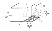
2階の階段付き建物ユニット3を建物ユニット1と比較すると、2階の階段付き建物ユニット3は、図2〜図4に示すように、矩形状の床パネル31と、この床パネル31の相対する短辺と長辺の3辺に立設された壁パネル32とからなることはほぼ同じであるが、床パネル31の一部が切り取られ(この床パネル31の下方に下階の天井パネルがある場合には、この天井パネルも同時に切り取られ)た切欠部35が設けられ、この切欠部35に階段6が設けられていることが異なる。
【0028】
階段6は、上がり口からこの壁パネル32に向かって上がる第一階段61と、第一階段に続く壁近傍に設けられた回り部分62と、この回り部分62に続き、第一階段61と反対方向に向かって上がる第二階段63と、第一階段61と第二階段63との間に設けられた仕切り壁64とからなる。
この階段6は、回り部分62にも階段が設けられている回り階段である。
そして、仕切り壁64は、図3に示すように、木材を矩形状に組み立てた枠641と、この枠641の中に差し渡された木製の桟材642と、この両側面に取り付けられた石膏ボード等の内壁材643とからなる。
【0029】
架設部材7は、図3に示すように、回り部分62の下側にある仕切り壁64の枠641を水平方向に延長してほぼ矩形状に組み立てた枠71とこの枠71の内部に設けた桟材72とからなる。即ち、この仕切り壁64の回り部分の下側を壁パネル32方向に水平方向に延長したものである。そして、この架設部材7の先端は壁パネル32にビス等で取り外し可能に連結され、この架設部材7の仕切り壁64と枠71との境界が切り取り可能になっている。
【0030】
この2階の階段付き建物ユニット3は、図1に示すように、1階の階段付き建物ユニット2の上に、平面視で階段部分をほぼ同じ位置にして据え付けられ、この2階の階段付き建物ユニット3の上に階段上建物ユニット4が、平面視で階段部分をほぼ同じにして据え付けられている。
【0031】
この2階の階段付き建物ユット3の下に据え付けられる1階の階段付き建物ユニット2を2階の階段付き建物ユニット3と比較すると、床パネルが切り取られてないこと、架設部材が設けられてないことが異なる。即ち、1階の階段付き建物ユニット2の階段の下側は昇降に関係ないので、1階の階段付き建物ユニット2には床パネルを切り取る必要がないのである。従って、架設部材を設けなくとも、仕切り壁が床パネルの上に強固に立設させることができる。尚、このように床パネルが切欠されてないので、この部分を収納スペースとして使用してもよい。
【0032】
又、2階の階段付き建物ユニット3の上に据え付けられる3階の階段上建物ユニット4は、床パネルの一部が切り取られ(この床パネル31の下方に2階の天井パネルがある場合には、この天井パネルも同時に切り取られ)、この部分が階段部分となっている。
【0033】
そして、この階段部分を平面視でほぼ同じ位置にして、2階の階段付き建物ユニット3の上に3階の階段上建物ユニット4を据え付けると、この床パネルの切り取られた階段部分を通って、2階の階段付き建物ユニット3の階段6を昇降できるようになっている。
屋根ユニット5は従来とほぼ同じであるので説明を省略する。
【0034】
次に、この3階建てユニット建物の施工方法について説明する。
工場で、建物ユニット1、1階の階段付き建物ユニット2、2階の階段付き建物ユニット3、3階の階段上建物ユニット4、屋根ユニット5等を製造する。
この建物ユニット1、1階の階段付き建物ユニット2、2階の階段付き建物ユニット3、3階の階段上建物ユニット4、屋根ユニット5等を一時保管したり、施工現場に運搬する。
【0035】
この際、2階の階段付き建物ユニット3では、第一階段61と第二階段63との間に設けられた仕切り壁64が、壁側が架設部材7を介して壁パネル32に連結され、上がり口側が第一階段61の上がり口の床パネル31に連結されるというように両側が取り付けられ、安定した状態になっている。従って、2階の階段付き建物ユニット3の単独でも仕切り壁64が宙づりになったり倒れることがない。従って、階段付き建物ユニット3のみでも安全に保管したり運搬することができる。
【0036】
施工現場では、予め、設けられている基礎9の上に5個の1階の建物ユニット1と、1個の1階の階段付き建物ユニット2を据え付け、この1階の5個の建物ユニット1の上にそれぞれ2階の建物ユニット1を据え付け、1階の階段付き建物ユニット2の上に2階の階段付き建物ユニット3を、階段部分を平面視でほぼ同じ位置にして据え付け、2階の5個の建物ユニット1の上にそれぞれ3階の建物ユニット1を据え付け、2階の階段付き建物ユニット3の上に3階の階段上建物ユニット4を据え付け、この3階の建物ユニット1と3階の階段上建物ユニット4との上に屋根ユニット5を取り付け、1階の階段付き建物ユニット2の仕切り壁と2階の階段付き建物ユニット3の仕切り壁64を連結した後、2階の階段付き建物ユニット3の架設部材7を取り除く。
【0037】
この際、架設部材7は、仕切り壁64から切り取り可能になっているし、壁から取り外すことができるようになっているので簡単に架設部材7を取り除くことができる。
このように架設部材7を取り除くと、この階段部分に架設部材7がなくなるので1階の階段付き建物ユニット2の階段から2階の階段付き建物ユニット3に支障なく昇降することができるようになる。
その他、種々な仕上げを行うとユニット建物Uが完成する。
【0038】
(実施例2)
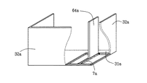
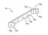
図5および図6は本発明の他の実施例を示すもので、図5は仕切り壁の取付構造を見易くするために、仕切り壁を残して階段を外し、手前の壁パネルの一部を切欠した状態の2階の階段付き建物ユニットを背後から見た一部切欠斜視図、図6は取付治具を示す斜視図である。
この図5および図6に示す実施例2を図1〜図4に示す実施例1と比較すると、架設部材がなく、仕切り壁64aの下端部に取り外し可能に取り付けられた取付治具7aが床パネル31aと壁パネル32aとに取り外し可能に連結されていることが異なる。
従って、この取付治具7aの構造およびこの取付治具7aを取り付けた仕切り壁64aの取付構造のみを更に詳細に説明する。
【0039】
この取付治具7aは、図6に示すように、厚みほぼ2.3mm、長さほぼ1980mm、幅ほぼ89mmの金属帯状体の本体74aと、この本体の両端に長さほぼ150mmのほぼ直角に折曲された状態に延設された鍔75aとからなる。この本体74a、鍔75aにはそれぞれ通孔76aが設けられている。
そして、この取付治具7aの2個で、図5に示すように、仕切り壁64aの下端部を両側から挟んだ状態にして、取付治具7aの通孔76aを通って仕切り壁64aに螺入されたネジ釘で取付治具7aが仕切り壁64aに取り付けられている。
【0040】
又、この2個の取付治具7aの一方の鍔75aを壁パネル32aに当接させ、鍔75aの通孔76aを通って壁パネル32aに螺入されたネジ釘で一方の鍔75aが壁パネル32aに連結されている。又、この2個の取付治具7aの他方の鍔75aを床パネル31aの端面に当接させ、鍔75aの通孔76aを通って床パネル31aの端面に螺入されたネジ釘で他方の鍔75aが床パネル31aに連結されている。
【0041】
従って、このネジ釘を螺出することにより、取付治具7aを壁パネル32a、床パネル31a、仕切り壁64aから簡単に取り外すことができるようになっている。
その他の構造は実施例1とほぼ同じであるので説明を省略する。
【0042】
次に、この3階建てユニット建物の施工方法について説明する。
工場で、建物ユニット、1階の階段付き建物ユニット、2階の階段付き建物ユニット3a、3階の階段上建物ユニット、屋根ユニット等を製造する。
この建物ユニット、1階の階段付き建物ユニット、2階の階段付き建物ユニット3a、3階の階段上建物ユニット、屋根ユニット等を一時保管したり、施工現場に運搬する。
【0043】
この際、2階の階段付き建物ユニット3aでは、仕切り壁64aが取付治具7aを介して壁パネル32aと床パネル31aとに連結されているから、この第一階段61aと第二階段63aとの間に設けられた仕切り壁64aは、安定した状態に取り付けられている。従って、階段付き建物ユニット3aは、単独でも仕切り壁64aが宙づりになったり倒れることがなく、この階段付き建物ユニット3aだけでも安全に保管したり運搬することができる。
【0044】
施工現場では、予め、設けられている基礎の上に5個の1階の建物ユニットと、1個の1階の階段付き建物ユニットを据え付け、この1階の5個の建物ユニットの上にそれぞれ2階の建物ユニットを据え付け、1階の階段付き建物ユニットの上に2階の階段付き建物ユニット3aを、階段部分を平面視でほぼ同じ位置にして据え付け、2階の5個の建物ユニットの上にそれぞれ建物ユニットを据え付け、2階の階段付き建物ユニットの上に3階の階段上建物ユニットを据え付け、この3階の建物ユニットと3階の階段上建物ユニットとの上に屋根ユニットを取り付け、1階の階段付き建物ユニットの仕切り壁と2階の階段付き建物ユニット3aの仕切り壁64aを連結した後、2階の階段付き建物ユニット3aの取付治具7aを取り外す。
【0045】
すると、この階段部分から取付治具7aがなくなるので、1階の階段付き建物ユニットの階段から2階の階段付き建物ユニット3aに支障なく昇降することができる。
その他、種々な仕上げを行うとユニット建物Uが完成する。
【0046】
以上、この発明を枠組壁工法の3階建てユニット建物に適用した実施例を詳述してきたが、本発明はこの枠組壁工法の3階建てユニット建物に限定されるものでなく、ラーメン構造の3階建てユニット建物にも適用できるし、その他の3階建てユニット建物にも適用できる。
【0047】
【発明の効果】
以上の説明で判るように、請求項1記載の発明は、矩形状の床の少なくとも1辺に壁が立設され、この壁に向かって上がる第一階段と、第一階段に続く壁近傍に設けられた回り部分と、この回り部分に続き、第一階段と反対方向に向かって上がる第二階段と、第一階段と第二階段との間に設けられた仕切り壁とからなる階段を備えた階段付き建物ユニットが下階及び上階にそれぞれ設けられたユニット建物であって、上階の前記階段付き建物ユニットは、その前記階段の位置が下階の前記階段付き建物ユニットの前記階段の位置と平面視でほぼ同じ位置になるように前記下階の階段付き建物ユニット上に据え付けられ、前記上階の階段付き建物ユニットに設けられた前記階段の前記仕切り壁は、その前記壁側と反対側に位置する一方の側縁部で前記上階の階段付き建物ユニットの第一階段の上がり口の床に連結されると共に、前記壁側に位置する他方の側縁部で前記上階の階段付き建物ユニットの前記壁に着脱自在な支持材を介して連結されているから、第一階段と第二階段との間に設けられた仕切り壁は安定した状態に取り付けられ、階段付き建物ユニットだけでも安全に保管したり運搬することができるし、又、この階段付き建物ユニットを1階の階段付き建物ユニットの上に据え付けた後に、この架設部材を外すと、階段の昇降に支障がなくなる。
【0048】
請求項2記載の発明は、前記支持材は、前記上階の階段付き建物ユニットの前記仕切り壁の回り部分の下側を水平方向に延長した架設部材であり、該架設部材の先端は、前記上階の階段付き建物ユニットの前記壁に取り外し可能に連結され、前記架設部材は、前記仕切り壁から切り取り可能になされているから、第一階段と第二階段との間に設けられた仕切り壁は安定した状態に取り付けられ、階段付き建物ユニットだけでも安全に保管したり運搬することができるし、又、この階段付き建物ユニットを1階の階段付き建物ユニットの上に据え付けた後に、この架設部材を切り取ると、階段の昇降に支障がなくなる。
【0049】
請求項3記載の発明は、矩形状の床の少なくとも1辺に壁が立設され、この壁に向かって上がる第一階段と、第一階段に続く壁近傍に設けられた回り部分と、この回り部分に続き、第一階段と反対方向に向かって上がる第二階段と、第一階段と第二階段との間に設けられた仕切り壁とからなる階段を備えた階段付き建物ユニットであって、前記仕切り壁には下端部に取付治具が取り外し可能に取り付けられ、この取付治具の一方が第一階段の上がり口の床に、他方が前記壁に、それぞれ取り外し可能に連結されているから、第一階段と第二階段との間に設けられた仕切り壁は安定した状態に取り付けられ、単独でも仕切り壁が宙づりになったり倒れることがなく、この階段付き建物ユニッだけでも安全に保管したり運搬することができるし、又、この階段付き建物ユニットを1階の階段付き建物ユニットと上に据え付けた後に、取付治具を壁、床、壁から外すと、階段の昇降に支障がなくなる。
【図面の簡単な説明】
【図1】本発明の階段付き建物ユニットを枠組壁工法の3階建てユニット建物に適用した一実施例を示すもので、ユニット建物の一部切欠斜視図である。
【図2】2階の階段付き建物ユニットの斜視図である。
【図3】仕切り壁の取付構造を見易くするために、、仕切り壁を残して階段を外し手前の壁パネルと仕切り壁の一部を切欠した状態の2階の階段付き建物ユニットを背後から見た一部切欠斜視図である。
【図4】建物ユニットの一部切欠斜視図である。
【図5】本発明の他の実施例を示すもので、仕切り壁の取付構造を見易くするために、仕切り壁を残して階段を外し、手前の壁パネルの一部を切欠した状態の2階の階段付き建物ユニットを背後から見た一部切欠斜視図である。
【図6】取付治具を示す斜視図である。
【符号の説明】
1 建物ユニット
2 1階の階段付き建物ユニット
3、3a 2階の階段付き建物ユニット
31、31a 床(床パネル)
32、32a 壁(壁パネル)
6 階段
61 第一階段
62 回り部分
63 第二階段
64、64a 仕切り壁
7 架設部材
7a 取付治具[0001]
BACKGROUND OF THE INVENTION
The present invention is a two-story building with a staircase used in a three-story unit building in which a building unit with a staircase on the first floor and a building unit with a staircase on the second floor are installed with the staircase portions in substantially the same position in plan view. The present invention relates to a building unit with stairs suitable for the unit.
In particular, the present invention relates to a building unit with stairs suitable for a three-story unit building of a frame wall construction method.
[0002]
[Prior art]
Three-story buildings have recently been attracting attention and are being built in large numbers because they can provide a large living area in a small residential area.
In this three-story building, in order to facilitate layout and elevate easily, the first-floor staircase portion and the second-floor staircase portion are often provided at substantially the same position in plan view.
[0003]
On the other hand, in the unit building, a box-shaped building unit with a certain size that can be transported, and internal and external finished building units are manufactured in advance at the factory, and a plurality of these building units are transported to the construction site. It is widely used because it is assembled at a construction site to form a building, has a feature of a standardized building with a short on-site construction period and good dimensional accuracy.
The building unit used in this unit building is a building unit with a ramen structure in which steel frames and wood are assembled into a ramen structure, and a framed wall construction method in which wall panels and floor panels with wall materials and floor materials attached to the frame are assembled. Many types of units are used.
[0004]
As shown in Japanese Patent Publication No. 62-62224, a typical building unit in which a steel frame is assembled into a ramen structure is composed of four steel pillars arranged at four corners of a square, and four pillars. It has a framework constructed of four steel floor beams that connect the lower ends along the sides and four steel ceiling beams that connect the upper ends of the four columns along the sides into a ramen structure. Then, a steel floor beam is passed to the opposite floor beam of this skeleton, a wooden floor joist is attached on this floor beam, and a flooring is attached on this floor joist to form a floor. A wooden ceiling nose is passed to the ceiling beam, and ceiling material is attached to the lower surface of the ceiling nose to form a ceiling. At the place where the wall is to be installed, a stud is attached between the ceiling beam and the floor beam. Install the outer wall on the outdoor side of the pillar and the inner wall on the indoor side, and install insulation between the inner wall and the outer wall. It is obtained by forming a wall Te.
[0005]
As typical building units of the frame wall construction method, as described in Japanese Patent Publication No. 58-30978 and Japanese Patent Application Laid-Open No. 61-204443, wall panels and floor panels having a wooden frame are manufactured. A floor panel and a wall panel are assembled in a box shape. In addition, a lower floor ceiling panel is attached to the lower floor building unit, and the upper floor building unit is installed on the lower floor building unit to form the lower floor ceiling. There are a lot of things.
[0006]
Even in this unit building, the number of three-story unit buildings is gradually increasing.
In this unit building, in order to reduce the number of on-site construction man-hours, a building unit with stairs with stairs attached to the building unit is manufactured in advance at the factory, and this unit is transported to the construction site and installed at the construction site. In many cases, the stairs are provided just by finishing.
[0007]
As such a building unit with a staircase, as described in JP-A-5-98707 and JP-A-7-76876, a building unit with a staircase having a substantially straight staircase, or Japanese Utility Model Publication No. 4-13310. As described in, the first staircase that rises toward the wall, the surrounding area of the landing that is located near the wall that follows the first staircase, and the second staircase that follows this circumference and rises in the opposite direction to the first staircase A building unit with a staircase including a second staircase and a staircase (hereinafter referred to as a U-shaped staircase) composed of a partition wall provided between the first staircase and the second staircase, and Japanese Patent Publication No. 3-50850 There is a building unit with a staircase or the like having a staircase (hereinafter referred to as a “turning staircase”) in which a rotating portion rises while rotating in place of the U-shaped staircase landing.
In particular, U-shaped staircases and swirl staircases are often used in unit buildings because the staircase portion can be compactly accommodated in one building unit.
[0008]
[Problems to be solved by the invention]
However, in this three-story unit building, in the same way as a normal building, in order to make it easy to arrange and to move up and down, the two-story building unit with a U-shaped staircase and a curved staircase are provided. When the building unit with a staircase on the floor is installed in a building with the staircase portions substantially in the same position in plan view, a difficult problem arises.
That is, the first floor ceiling and the second floor stairs are cut away so that a person going up and down through the first floor stairs can pass. Also, the ceiling on the 2nd floor and the staircase on the 3rd floor are cut out so that people who go up and down to the 3rd floor can pass through the 2nd floor stairs. That is, there is no floor or ceiling in the staircase portion of the second floor building unit between the first and third floors.
[0009]
Therefore, when the building unit with a staircase on the second floor is alone, it can be attached to the floor or ceiling on the side of the rising wall of the partition wall between the first staircase and the second staircase, but the wall and partition wall on the wall side of the partition wall There is a stairway between them, and it is an up-and-down passage, and since there is no upper or lower floor or ceiling, the wall side of this partition wall cannot be attached anywhere and this part is suspended. Even if the wall side of the partition wall is suspended and the indoor side of the partition wall is installed and supported on the floor or ceiling of the outlet or outlet, it is difficult to support the partition wall because the partition wall is heavy.
[0010]
In particular, in the frame wall construction method described in the above publication, since the ceiling is not provided, it is necessary to support the partition wall only by the floor portion of the rising mouth, so that it is almost impossible.
Since it has such a structure, there is a problem that the building unit with the stairs on the second floor cannot be transported or stored alone.
After installing the building unit with the second floor on the first floor building unit, the partition wall of the building unit with the second floor is placed on the partition wall of the building unit with the first floor. Since it is connected, there is no problem, and the above problem is a problem when only the building unit with stairs is used.
[0011]
Therefore, an object of the present invention is a U-shaped staircase or a rotating staircase, and a building unit with a staircase that can be stored and transported independently even if a partition wall is provided between the first staircase and the second staircase. And unit buildings Is to provide.
[0012]
[Means for Solving the Problems]
The present invention has been made to achieve the above object, and the invention according to
[0013]
In the first aspect of the present invention, the partition wall is connected to the rising floor of the first staircase. However, the partition wall may be directly connected to the rising floor as described in the second aspect. You may connect through a material. The partition wall is connected to the floor and wall of the rising opening via a detachable support material. There are various types of support materials. For example, the partition wall may be extended as described in
[0014]
That is, the invention according to
[0015]
According to a third aspect of the present invention, a wall is erected on at least one side of a rectangular floor, and a first step rising toward the wall, and a surrounding portion provided near the wall following the first step, This is a building unit with a staircase that has a staircase consisting of a second staircase that goes in the opposite direction to the first staircase, and a partition wall provided between the first staircase and the second staircase. An attachment jig is removably attached to the lower end of the partition wall, and one of the attachment jigs is removably connected to the floor of the first staircase and the other to the wall. It is what.
[0016]
In the present invention, the first staircase in which the staircase rises toward the wall, the surrounding portion provided in the vicinity of the wall following the first staircase, and the second staircase that follows the surrounding portion and rises in the opposite direction to the first staircase And a partition wall provided between the first staircase and the second staircase, the staircase may be a rotating staircase whose surrounding portion is a staircase, or the surrounding portion may be a landing It may be a U-shaped staircase.
[0017]
(Function)
In the first aspect of the present invention, the partition wall is connected to the floor of the first staircase and connected to the wall via a support member. Between the staircase, the surrounding part provided near the wall following the first staircase, the second staircase that follows this surrounding part and goes in the opposite direction to the first staircase, and the first staircase and the second staircase Even in a building unit with a staircase that has a staircase consisting of a partition wall, the partition wall provided between the first staircase and the second staircase is supported by both the wall and the floor of the outlet. It is attached in a stable state. Therefore, even if it is independent, a partition wall does not hang or fall down, and only a building unit with stairs can be safely stored and transported.
[0018]
Moreover, since this support material is detachable, this building unit with stairs is installed on the building unit with stairs on the first floor, and after the partition wall on the second floor is connected to the partition wall on the first floor, When the member is removed, there is no erection member in the staircase, and there is no hindrance to raising or lowering the staircase.
[0019]
In the invention of
[0020]
In addition, since this erection member is detachably connected to the wall and can be cut off from the partition wall, the building unit with stairs is installed on the building unit with stairs on the first floor, and the top of the partition wall on the first floor. If the installation member is removed from the wall or cut out from the partition wall after the partition walls on the second floor are connected to each other, there is no partition wall at the staircase portion, and there is no hindrance to raising and lowering the stairs.
[0021]
In the invention according to
[0022]
Moreover, since this mounting jig can be removed from the partition wall, floor, and wall, this building unit with stairs is installed on top of the building unit with stairs on the first floor, and the second floor above the partition wall on the first floor. After connecting the partition walls, removing the mounting jig from the wall, floor, or wall eliminates the hindrance to raising or lowering the stairs.
[0023]
DETAILED DESCRIPTION OF THE INVENTION
Next, the embodiments of the present invention will be described by way of examples.
Example 1
1 to 4 show an embodiment in which the building unit with stairs of the present invention is applied to a three-story unit building of a frame wall construction method. FIG. 1 is a partially cutaway perspective view of the unit building, and FIG. 3 is a perspective view of the building unit with stairs on the floor, Fig. 3 shows the second floor with the partition wall removed and the stairs removed, and the front wall panel and part of the partition wall cut away to make the partition wall mounting structure easier to see. FIG. 4 is a partially cutaway perspective view of the building unit with stairs as seen from behind, and FIG. 4 is a partially cutaway perspective view of the building unit.
[0024]
1 to 4, U is a three-story unit building. As shown in FIG. 1, this three-story unit building U includes five first-
[0025]
As shown in FIG. 4, the
The
The
[0026]
The
[0027]
Comparing the
[0028]
The
This
As shown in FIG. 3, the
[0029]
As shown in FIG. 3, the
[0030]
As shown in FIG. 1, the
[0031]
Comparing the
[0032]
In addition, the third floor
[0033]
And when this staircase part is set in the almost same position in plan view and the third floor
Since the
[0034]
Next, the construction method of this three-story unit building will be described.
At the factory, a
The
[0035]
At this time, in the
[0036]
At the construction site, five
[0037]
At this time, the
When the
In addition, the unit building U is completed when various finishing is performed.
[0038]
(Example 2)
FIGS. 5 and 6 show another embodiment of the present invention. FIG. 5 shows that the partition wall is removed and the stairs are removed to make the partition wall mounting structure easier to see, and a part of the front wall panel is cut away. FIG. 6 is a perspective view showing a mounting jig with a partially cutaway perspective view of a building unit with a staircase on the second floor in a state of being viewed from behind.
5 and FIG. 6 is compared with Example 1 shown in FIGS. 1 to 4, there is no installation member, and the mounting jig 7a removably attached to the lower end portion of the
Therefore, only the structure of the mounting jig 7a and the mounting structure of the
[0039]
As shown in FIG. 6, the mounting jig 7a includes a
Then, with the two mounting jigs 7a, as shown in FIG. 5, the lower end portion of the
[0040]
Also, one
[0041]
Therefore, by screwing out the screw nails, the mounting jig 7a can be easily removed from the
Since other structures are almost the same as those of the first embodiment, description thereof is omitted.
[0042]
Next, the construction method of this three-story unit building will be described.
The factory manufactures building units, building units with stairs on the first floor, building units 3a with stairs on the second floor, building units on the stairs on the third floor, roof units, and the like.
The building unit, the first floor building unit with stairs, the second floor building unit 3a, the third floor building unit with stairs, the roof unit, etc. are temporarily stored or transported to the construction site.
[0043]
At this time, in the building unit 3a with stairs on the second floor, since the
[0044]
At the construction site, five first-floor building units and one first-floor building unit with a staircase are installed on a foundation that has been set up in advance, and each of the five building units on the first floor is placed on top of each other. Install the building unit on the 2nd floor, install the building unit 3a with the 2nd floor on the 1st floor building unit with the stairs part in the same position in plan view, and install the 5 building units on the 2nd floor The building unit is installed on the top, the building unit on the 3rd floor is installed on the building unit with the 2nd floor staircase, and the roof unit is installed on the building unit on the 3rd floor and the building unit on the 3rd floor. After connecting the partition wall of the building unit with stairs on the first floor and the
[0045]
Then, since the mounting jig 7a is eliminated from the staircase portion, the staircase of the building unit with stairs on the first floor can be moved up and down without difficulty to the building unit 3a with stairs on the second floor.
In addition, the unit building U is completed when various finishing is performed.
[0046]
As mentioned above, although the Example which applied this invention to the three-story unit building of a frame wall construction method was explained in full detail, this invention is not limited to the three-story unit building of this frame wall construction method, It can be applied to a three-story unit building, and can also be applied to other three-story unit buildings.
[0047]
【The invention's effect】
As can be seen from the above description, the invention according to
[0048]
The invention according to
[0049]
The invention according to
[Brief description of the drawings]
FIG. 1 is a partially cutaway perspective view of a unit building, showing an embodiment in which a building unit with stairs of the present invention is applied to a three-story unit building of a frame wall construction method.
FIG. 2 is a perspective view of a building unit with stairs on the second floor.
[Fig. 3] In order to make the partition wall mounting structure easier to see, the building unit with a staircase on the second floor is viewed from behind, with the partition wall removed and the stairs removed, with the front wall panel and part of the partition wall cut away. FIG.
FIG. 4 is a partially cutaway perspective view of a building unit.
FIG. 5 shows another embodiment of the present invention, in order to make the mounting structure of the partition wall easier to see, the second floor in a state in which the stairs are removed leaving the partition wall and a part of the front wall panel is cut away; It is the partially cutaway perspective view which looked at the building unit with a staircase from the back.
FIG. 6 is a perspective view showing an attachment jig.
[Explanation of symbols]
1 Building unit
2 Building unit with stairs on the 1st floor
3, 3a 2nd floor building unit with stairs
31, 31a Floor (floor panel)
32, 32a Wall (wall panel)
6 stairs
61 First staircase
62 Around
63 Second stairs
64, 64a partition wall
7 Construction members
7a Mounting jig
Claims (3)
Priority Applications (1)
| Application Number | Priority Date | Filing Date | Title |
|---|---|---|---|
| JP07998999A JP3999907B2 (en) | 1999-03-24 | 1999-03-24 | Building unit with stairs and unit building |
Applications Claiming Priority (1)
| Application Number | Priority Date | Filing Date | Title |
|---|---|---|---|
| JP07998999A JP3999907B2 (en) | 1999-03-24 | 1999-03-24 | Building unit with stairs and unit building |
Publications (2)
| Publication Number | Publication Date |
|---|---|
| JP2000273963A JP2000273963A (en) | 2000-10-03 |
| JP3999907B2 true JP3999907B2 (en) | 2007-10-31 |
Family
ID=13705730
Family Applications (1)
| Application Number | Title | Priority Date | Filing Date |
|---|---|---|---|
| JP07998999A Expired - Fee Related JP3999907B2 (en) | 1999-03-24 | 1999-03-24 | Building unit with stairs and unit building |
Country Status (1)
| Country | Link |
|---|---|
| JP (1) | JP3999907B2 (en) |
Families Citing this family (1)
| Publication number | Priority date | Publication date | Assignee | Title |
|---|---|---|---|---|
| JP7044572B2 (en) * | 2018-01-25 | 2022-03-30 | 積水化学工業株式会社 | Staircase structure and unit building |
-
1999
- 1999-03-24 JP JP07998999A patent/JP3999907B2/en not_active Expired - Fee Related
Also Published As
| Publication number | Publication date |
|---|---|
| JP2000273963A (en) | 2000-10-03 |
Similar Documents
| Publication | Publication Date | Title |
|---|---|---|
| JP3999907B2 (en) | Building unit with stairs and unit building | |
| US4955174A (en) | Expandable building with modular roof system | |
| JP7426974B2 (en) | Stairway construction method and stairway structure | |
| JP7310502B2 (en) | Opening construction method | |
| JP5970306B2 (en) | building | |
| JP3924050B2 (en) | Unit building | |
| JPH046439Y2 (en) | ||
| JP3168257B2 (en) | Construction method of wooden house | |
| JPH076296Y2 (en) | Outdoor stair structure | |
| JP2519384B2 (en) | Auxiliary surface of wooden prefabricated building | |
| JPS6217527Y2 (en) | ||
| JPH06346517A (en) | Unit type building | |
| JP3443459B2 (en) | Balcony unit and corridor unit support structure | |
| JP2002004464A (en) | Ventilation execusion structure for bearing wall | |
| JP2000073594A (en) | Building with solar cell roof | |
| JPH04363432A (en) | Stairway landing unit | |
| JP2003082769A (en) | Building unit | |
| JPH04182559A (en) | Structure of outdoor stairway | |
| JPH11181890A (en) | Building unit with stairs and unit building using the building unit | |
| JPH10325181A (en) | Stair box for use in two-by-four house construction method and method for constructing two-by-four house | |
| JP2003253765A (en) | Unit building | |
| JPH08209876A (en) | Stairs structure of unit type building | |
| JPH07100960B2 (en) | Floor structure of a house | |
| JP2000045547A (en) | Building with solar battery | |
| JPH074602U (en) | Unit building |
Legal Events
| Date | Code | Title | Description |
|---|---|---|---|
| A621 | Written request for application examination |
Free format text: JAPANESE INTERMEDIATE CODE: A621 Effective date: 20051021 |
|
| A977 | Report on retrieval |
Free format text: JAPANESE INTERMEDIATE CODE: A971007 Effective date: 20070424 |
|
| A131 | Notification of reasons for refusal |
Free format text: JAPANESE INTERMEDIATE CODE: A131 Effective date: 20070509 |
|
| A521 | Written amendment |
Free format text: JAPANESE INTERMEDIATE CODE: A523 Effective date: 20070625 |
|
| TRDD | Decision of grant or rejection written | ||
| A01 | Written decision to grant a patent or to grant a registration (utility model) |
Free format text: JAPANESE INTERMEDIATE CODE: A01 Effective date: 20070718 |
|
| A61 | First payment of annual fees (during grant procedure) |
Free format text: JAPANESE INTERMEDIATE CODE: A61 Effective date: 20070810 |
|
| FPAY | Renewal fee payment (event date is renewal date of database) |
Free format text: PAYMENT UNTIL: 20100817 Year of fee payment: 3 |
|
| FPAY | Renewal fee payment (event date is renewal date of database) |
Free format text: PAYMENT UNTIL: 20110817 Year of fee payment: 4 |
|
| FPAY | Renewal fee payment (event date is renewal date of database) |
Free format text: PAYMENT UNTIL: 20110817 Year of fee payment: 4 |
|
| FPAY | Renewal fee payment (event date is renewal date of database) |
Free format text: PAYMENT UNTIL: 20120817 Year of fee payment: 5 |
|
| FPAY | Renewal fee payment (event date is renewal date of database) |
Free format text: PAYMENT UNTIL: 20120817 Year of fee payment: 5 |
|
| FPAY | Renewal fee payment (event date is renewal date of database) |
Free format text: PAYMENT UNTIL: 20130817 Year of fee payment: 6 |
|
| LAPS | Cancellation because of no payment of annual fees |