JP3977807B2 - Processing and equipment for handling workpieces such as semiconductor wafers - Google Patents
Processing and equipment for handling workpieces such as semiconductor wafers Download PDFInfo
- Publication number
- JP3977807B2 JP3977807B2 JP2003519981A JP2003519981A JP3977807B2 JP 3977807 B2 JP3977807 B2 JP 3977807B2 JP 2003519981 A JP2003519981 A JP 2003519981A JP 2003519981 A JP2003519981 A JP 2003519981A JP 3977807 B2 JP3977807 B2 JP 3977807B2
- Authority
- JP
- Japan
- Prior art keywords
- workpiece
- liquid
- ozone
- jet
- processing
- Prior art date
- Legal status (The legal status is an assumption and is not a legal conclusion. Google has not performed a legal analysis and makes no representation as to the accuracy of the status listed.)
- Expired - Fee Related
Links
Images


Classifications
-
- H—ELECTRICITY
- H01—ELECTRIC ELEMENTS
- H01L—SEMICONDUCTOR DEVICES NOT COVERED BY CLASS H10
- H01L21/00—Processes or apparatus adapted for the manufacture or treatment of semiconductor or solid state devices or of parts thereof
- H01L21/02—Manufacture or treatment of semiconductor devices or of parts thereof
- H01L21/04—Manufacture or treatment of semiconductor devices or of parts thereof the devices having at least one potential-jump barrier or surface barrier, e.g. PN junction, depletion layer or carrier concentration layer
- H01L21/18—Manufacture or treatment of semiconductor devices or of parts thereof the devices having at least one potential-jump barrier or surface barrier, e.g. PN junction, depletion layer or carrier concentration layer the devices having semiconductor bodies comprising elements of Group IV of the Periodic System or AIIIBV compounds with or without impurities, e.g. doping materials
- H01L21/30—Treatment of semiconductor bodies using processes or apparatus not provided for in groups H01L21/20 - H01L21/26
- H01L21/302—Treatment of semiconductor bodies using processes or apparatus not provided for in groups H01L21/20 - H01L21/26 to change their surface-physical characteristics or shape, e.g. etching, polishing, cutting
- H01L21/304—Mechanical treatment, e.g. grinding, polishing, cutting
-
- H—ELECTRICITY
- H01—ELECTRIC ELEMENTS
- H01L—SEMICONDUCTOR DEVICES NOT COVERED BY CLASS H10
- H01L21/00—Processes or apparatus adapted for the manufacture or treatment of semiconductor or solid state devices or of parts thereof
- H01L21/02—Manufacture or treatment of semiconductor devices or of parts thereof
- H01L21/02041—Cleaning
- H01L21/02043—Cleaning before device manufacture, i.e. Begin-Of-Line process
- H01L21/02052—Wet cleaning only
-
- B—PERFORMING OPERATIONS; TRANSPORTING
- B08—CLEANING
- B08B—CLEANING IN GENERAL; PREVENTION OF FOULING IN GENERAL
- B08B3/00—Cleaning by methods involving the use or presence of liquid or steam
-
- B—PERFORMING OPERATIONS; TRANSPORTING
- B08—CLEANING
- B08B—CLEANING IN GENERAL; PREVENTION OF FOULING IN GENERAL
- B08B3/00—Cleaning by methods involving the use or presence of liquid or steam
- B08B3/02—Cleaning by the force of jets or sprays
-
- B—PERFORMING OPERATIONS; TRANSPORTING
- B08—CLEANING
- B08B—CLEANING IN GENERAL; PREVENTION OF FOULING IN GENERAL
- B08B3/00—Cleaning by methods involving the use or presence of liquid or steam
- B08B3/04—Cleaning involving contact with liquid
- B08B3/044—Cleaning involving contact with liquid using agitated containers in which the liquid and articles or material are placed
-
- B—PERFORMING OPERATIONS; TRANSPORTING
- B08—CLEANING
- B08B—CLEANING IN GENERAL; PREVENTION OF FOULING IN GENERAL
- B08B3/00—Cleaning by methods involving the use or presence of liquid or steam
- B08B3/04—Cleaning involving contact with liquid
- B08B3/08—Cleaning involving contact with liquid the liquid having chemical or dissolving effect
-
- B—PERFORMING OPERATIONS; TRANSPORTING
- B08—CLEANING
- B08B—CLEANING IN GENERAL; PREVENTION OF FOULING IN GENERAL
- B08B7/00—Cleaning by methods not provided for in a single other subclass or a single group in this subclass
-
- H—ELECTRICITY
- H01—ELECTRIC ELEMENTS
- H01L—SEMICONDUCTOR DEVICES NOT COVERED BY CLASS H10
- H01L21/00—Processes or apparatus adapted for the manufacture or treatment of semiconductor or solid state devices or of parts thereof
- H01L21/02—Manufacture or treatment of semiconductor devices or of parts thereof
- H01L21/02041—Cleaning
- H01L21/02043—Cleaning before device manufacture, i.e. Begin-Of-Line process
- H01L21/02054—Cleaning before device manufacture, i.e. Begin-Of-Line process combining dry and wet cleaning steps
-
- H—ELECTRICITY
- H01—ELECTRIC ELEMENTS
- H01L—SEMICONDUCTOR DEVICES NOT COVERED BY CLASS H10
- H01L21/00—Processes or apparatus adapted for the manufacture or treatment of semiconductor or solid state devices or of parts thereof
- H01L21/02—Manufacture or treatment of semiconductor devices or of parts thereof
- H01L21/04—Manufacture or treatment of semiconductor devices or of parts thereof the devices having at least one potential-jump barrier or surface barrier, e.g. PN junction, depletion layer or carrier concentration layer
- H01L21/18—Manufacture or treatment of semiconductor devices or of parts thereof the devices having at least one potential-jump barrier or surface barrier, e.g. PN junction, depletion layer or carrier concentration layer the devices having semiconductor bodies comprising elements of Group IV of the Periodic System or AIIIBV compounds with or without impurities, e.g. doping materials
- H01L21/30—Treatment of semiconductor bodies using processes or apparatus not provided for in groups H01L21/20 - H01L21/26
- H01L21/302—Treatment of semiconductor bodies using processes or apparatus not provided for in groups H01L21/20 - H01L21/26 to change their surface-physical characteristics or shape, e.g. etching, polishing, cutting
- H01L21/306—Chemical or electrical treatment, e.g. electrolytic etching
- H01L21/3065—Plasma etching; Reactive-ion etching
-
- H—ELECTRICITY
- H01—ELECTRIC ELEMENTS
- H01L—SEMICONDUCTOR DEVICES NOT COVERED BY CLASS H10
- H01L21/00—Processes or apparatus adapted for the manufacture or treatment of semiconductor or solid state devices or of parts thereof
- H01L21/67—Apparatus specially adapted for handling semiconductor or electric solid state devices during manufacture or treatment thereof; Apparatus specially adapted for handling wafers during manufacture or treatment of semiconductor or electric solid state devices or components ; Apparatus not specifically provided for elsewhere
- H01L21/67005—Apparatus not specifically provided for elsewhere
- H01L21/67011—Apparatus for manufacture or treatment
- H01L21/67017—Apparatus for fluid treatment
- H01L21/67028—Apparatus for fluid treatment for cleaning followed by drying, rinsing, stripping, blasting or the like
- H01L21/67034—Apparatus for fluid treatment for cleaning followed by drying, rinsing, stripping, blasting or the like for drying
-
- H—ELECTRICITY
- H01—ELECTRIC ELEMENTS
- H01L—SEMICONDUCTOR DEVICES NOT COVERED BY CLASS H10
- H01L21/00—Processes or apparatus adapted for the manufacture or treatment of semiconductor or solid state devices or of parts thereof
- H01L21/67—Apparatus specially adapted for handling semiconductor or electric solid state devices during manufacture or treatment thereof; Apparatus specially adapted for handling wafers during manufacture or treatment of semiconductor or electric solid state devices or components ; Apparatus not specifically provided for elsewhere
- H01L21/67005—Apparatus not specifically provided for elsewhere
- H01L21/67011—Apparatus for manufacture or treatment
- H01L21/67017—Apparatus for fluid treatment
- H01L21/67028—Apparatus for fluid treatment for cleaning followed by drying, rinsing, stripping, blasting or the like
- H01L21/6704—Apparatus for fluid treatment for cleaning followed by drying, rinsing, stripping, blasting or the like for wet cleaning or washing
- H01L21/67051—Apparatus for fluid treatment for cleaning followed by drying, rinsing, stripping, blasting or the like for wet cleaning or washing using mainly spraying means, e.g. nozzles
-
- H—ELECTRICITY
- H01—ELECTRIC ELEMENTS
- H01L—SEMICONDUCTOR DEVICES NOT COVERED BY CLASS H10
- H01L23/00—Details of semiconductor or other solid state devices
- H01L23/48—Arrangements for conducting electric current to or from the solid state body in operation, e.g. leads, terminal arrangements ; Selection of materials therefor
- H01L23/488—Arrangements for conducting electric current to or from the solid state body in operation, e.g. leads, terminal arrangements ; Selection of materials therefor consisting of soldered or bonded constructions
- H01L23/495—Lead-frames or other flat leads
- H01L23/49579—Lead-frames or other flat leads characterised by the materials of the lead frames or layers thereon
- H01L23/49582—Metallic layers on lead frames
-
- H—ELECTRICITY
- H05—ELECTRIC TECHNIQUES NOT OTHERWISE PROVIDED FOR
- H05K—PRINTED CIRCUITS; CASINGS OR CONSTRUCTIONAL DETAILS OF ELECTRIC APPARATUS; MANUFACTURE OF ASSEMBLAGES OF ELECTRICAL COMPONENTS
- H05K3/00—Apparatus or processes for manufacturing printed circuits
- H05K3/30—Assembling printed circuits with electric components, e.g. with resistor
- H05K3/32—Assembling printed circuits with electric components, e.g. with resistor electrically connecting electric components or wires to printed circuits
- H05K3/34—Assembling printed circuits with electric components, e.g. with resistor electrically connecting electric components or wires to printed circuits by soldering
- H05K3/341—Surface mounted components
- H05K3/3421—Leaded components
- H05K3/3426—Leaded components characterised by the leads
-
- B—PERFORMING OPERATIONS; TRANSPORTING
- B08—CLEANING
- B08B—CLEANING IN GENERAL; PREVENTION OF FOULING IN GENERAL
- B08B2203/00—Details of cleaning machines or methods involving the use or presence of liquid or steam
- B08B2203/005—Details of cleaning machines or methods involving the use or presence of liquid or steam the liquid being ozonated
-
- B—PERFORMING OPERATIONS; TRANSPORTING
- B08—CLEANING
- B08B—CLEANING IN GENERAL; PREVENTION OF FOULING IN GENERAL
- B08B2203/00—Details of cleaning machines or methods involving the use or presence of liquid or steam
- B08B2203/007—Heating the liquid
-
- B—PERFORMING OPERATIONS; TRANSPORTING
- B08—CLEANING
- B08B—CLEANING IN GENERAL; PREVENTION OF FOULING IN GENERAL
- B08B2203/00—Details of cleaning machines or methods involving the use or presence of liquid or steam
- B08B2203/02—Details of machines or methods for cleaning by the force of jets or sprays
- B08B2203/0288—Ultra or megasonic jets
-
- B—PERFORMING OPERATIONS; TRANSPORTING
- B08—CLEANING
- B08B—CLEANING IN GENERAL; PREVENTION OF FOULING IN GENERAL
- B08B2230/00—Other cleaning aspects applicable to all B08B range
- B08B2230/01—Cleaning with steam
-
- H—ELECTRICITY
- H01—ELECTRIC ELEMENTS
- H01L—SEMICONDUCTOR DEVICES NOT COVERED BY CLASS H10
- H01L2924/00—Indexing scheme for arrangements or methods for connecting or disconnecting semiconductor or solid-state bodies as covered by H01L24/00
- H01L2924/0001—Technical content checked by a classifier
- H01L2924/0002—Not covered by any one of groups H01L24/00, H01L24/00 and H01L2224/00
-
- Y—GENERAL TAGGING OF NEW TECHNOLOGICAL DEVELOPMENTS; GENERAL TAGGING OF CROSS-SECTIONAL TECHNOLOGIES SPANNING OVER SEVERAL SECTIONS OF THE IPC; TECHNICAL SUBJECTS COVERED BY FORMER USPC CROSS-REFERENCE ART COLLECTIONS [XRACs] AND DIGESTS
- Y02—TECHNOLOGIES OR APPLICATIONS FOR MITIGATION OR ADAPTATION AGAINST CLIMATE CHANGE
- Y02P—CLIMATE CHANGE MITIGATION TECHNOLOGIES IN THE PRODUCTION OR PROCESSING OF GOODS
- Y02P70/00—Climate change mitigation technologies in the production process for final industrial or consumer products
- Y02P70/50—Manufacturing or production processes characterised by the final manufactured product
Abstract
Description
この発明は、半導体ウエハなどのフラットメディアワークピースを洗浄する方法、およびワークピースから汚染物質を除去する装置に関する。半導体装置は、コミュニケーション、医用、産業用、軍用、およびオフィス用の製品や設備と同様に、電話、コンピュータ、CDプレーヤなど、ほとんど全ての消費電子製品に広く使用されている。半導体装置は、半導体ウエハから製造される。半導体ウエハの洗浄は、多くの場合、半導体装置の製造に使用される製作処理における重要なステップとなっている。多くの場合、ウエハ上の形状は数分の1ミクロンのオーダーであり、一方膜の厚さは20オングストロームのオーダーであってもよい。このため、ウエハから製造された装置は、有機物質汚染、微粒子汚染、または、金属/イオン汚染による、性能劣化または破損に、著しく影響されやすくなる。二次加工構造(fabrication structure)に使用される二酸化珪素でさえ、酸化物の品質または厚さが設計パラメータに合わない場合は、汚染物質であると見なされ得る。 The present invention relates to a method for cleaning a flat media workpiece, such as a semiconductor wafer, and an apparatus for removing contaminants from the workpiece. Semiconductor devices are widely used in almost all consumer electronic products such as telephones, computers, CD players, as well as communications, medical, industrial, military, and office products and equipment. The semiconductor device is manufactured from a semiconductor wafer. Semiconductor wafer cleaning is often an important step in the fabrication process used to manufacture semiconductor devices. In many cases, the shape on the wafer may be on the order of a fraction of a micron, while the film thickness may be on the order of 20 angstroms. Thus, devices manufactured from wafers are significantly susceptible to performance degradation or breakage due to organic contamination, particulate contamination, or metal / ion contamination. Even silicon dioxide used in the fabrication structure can be considered a contaminant if the quality or thickness of the oxide does not meet the design parameters.
ウエハ洗浄には長い歴史があるが、「近代の」洗浄技術の時代は、一般に、RCAが様々なタイプの汚染を処理する洗浄シーケンスを開発した、1970年代前半に始まったと考えられている。同じタイムフレームにおいて、他にも、同一の、または同様のプロセスを開発したものもあったが、最終的な形態での概略的な洗浄シーケンスは基本的に同一である。 Although wafer cleaning has a long history, the era of “modern” cleaning technology is generally thought to have started in the early 1970s, when RCA developed cleaning sequences to handle various types of contamination. While others have developed the same or similar processes in the same time frame, the general cleaning sequence in the final form is basically the same.
RCA洗浄シーケンスの第1のステップは、硫酸および過酸化水素の混合液を用いる、有機汚染の除去を含んでいる。比率は、90〜140℃の範囲の温度で、通常2:1〜20:1の範囲である。この混合液は、一般に「ピラニア」と呼ばれている。有機汚染の除去に対する近年の強化では、過酸化水素を、発泡され、または硫酸ラインへ注入されるオゾンで置換している。 The first step of the RCA cleaning sequence involves the removal of organic contamination using a mixture of sulfuric acid and hydrogen peroxide. The ratio is usually in the range of 2: 1 to 20: 1 at a temperature in the range of 90-140 ° C. This mixed solution is generally called “piranha”. Recent enhancements to the removal of organic contamination have replaced hydrogen peroxide with ozone that is foamed or injected into the sulfuric acid line.
処理の第2のステップは、通常は周囲温度において、200:1〜10:1の比率の水およびHF(49%)で、酸化薄膜を除去することである。この処理により、通常、ウエハの領域を疎水性状態に残すことになる。 The second step in the process is to remove the oxide film with water and HF (49%) in a ratio of 200: 1 to 10: 1, usually at ambient temperature. This process typically leaves the wafer area in a hydrophobic state.
処理の次のステップは、通常はおよそ60‐70℃の温度で、水、過酸化水素、および水酸化アンモニウムの混合液を用いる、疎水性シリコン表面の粒子および再酸化の除去を含んでいる。沿革的に、これらの成分の比率は、5:1:1のオーダーとなっている。近年その比率は、より一般的に、5:1:0.25、または、より希釈するものとなっている。この混合液は、一般に「SC1」(スタンダードクリーン1)、またはRCA1と呼ばれている。代替的に、これは、HUANG1としても知られている。処理のこの部分は、(粒子除去に都合の良いゼータポテンシャルの生成と関連して)むき出しのシリコンウエハ表面上に二酸化珪素膜を成長させ、同時に腐食除去することにより、粒子を除去する傑出したジョブである一方で、溶液中の鉄やアルミニウムなどの金属を、シリコン表面上へ付着させかねないという欠点を有している。 The next step of the treatment involves removal of particles and reoxidation of the hydrophobic silicon surface using a mixture of water, hydrogen peroxide and ammonium hydroxide, usually at a temperature of approximately 60-70 ° C. Historically, the ratio of these components is on the order of 5: 1: 1. In recent years, the ratio has become more commonly 5: 1: 0.25 or more dilute. This mixed solution is generally called “SC1” (standard clean 1) or RCA1. Alternatively, this is also known as HUANG1. This part of the process is an outstanding job to remove particles by growing a silicon dioxide film on a bare silicon wafer surface (in conjunction with the generation of a zeta potential that is convenient for particle removal) and at the same time corrosive removal. On the other hand, it has a drawback that metals such as iron and aluminum in the solution may adhere to the silicon surface.
処理の最後の部分では、金属が、水、過酸化水素、および塩酸の混合液で、除去される。通常、この除去は、およそ60‐70℃で実行される。沿革的に、比率は5:1:1のオーダーであったが、最近の進展では、水およびHC1の希釈混合液を含む、より希薄な化学物質も有効であることが示されている。この混合液は、一般に「SC2」(スタンダードクリーン2)、RCA2、またはHUANG2と呼ばれている。 In the last part of the process, the metal is removed with a mixture of water, hydrogen peroxide and hydrochloric acid. Usually this removal is performed at approximately 60-70 ° C. Historically, ratios were on the order of 5: 1: 1, but recent developments have shown that even more dilute chemicals, including dilute mixtures of water and HC1, are also effective. This liquid mixture is generally called “SC2” (Standard Clean 2), RCA2, or HUANG2.
上記のステップは、多くの場合、いわゆる「プレ拡散洗浄」と呼ばれることを構成するシーケンスにおいて実行される。こうしたプレ拡散洗浄は、装置を役立たなくさせるような形で、装置層に不純物を取り込んだり、または拡散させる可能性のある熱的動作以前に、ウエハが非常に清潔な状態にあることを保証するものである。この4ステップ洗浄処理は、半導体産業における標準洗浄処理と考え得るが、同一サブ成分を用いる、多くの異形処理が存在する。例えば、以下の処理シーケンスをもたらすピラニア溶液は処理から削除されてもよい:HF _ >SC1 _>SC2。近年、薄い酸化物が、装置の性能における問題となっているため、「フッ化水素酸最終(hydrofluoric acid last)」化学物質が開発されている。こうした例では、ウエハ表面からシリコン背面を除去するために、塩酸を含む最終洗浄を伴って、1つ以上の上述の洗浄ステップが採用されている。 The above steps are often performed in a sequence that constitutes what is called “pre-diffusion cleaning”. Such pre-diffusion cleaning ensures that the wafer is in a very clean state prior to thermal operation that can introduce or diffuse impurities into the device layer in a way that renders the device useless. Is. This four-step cleaning process can be considered as a standard cleaning process in the semiconductor industry, but there are many variant processes that use the same sub-components. For example, a piranha solution that results in the following processing sequence may be deleted from the process: HF_> SC1_> SC2. In recent years, “hydrofluoric acid last” chemicals have been developed because thin oxides have become a problem in device performance. In such an example, one or more of the above-described cleaning steps are employed with a final cleaning including hydrochloric acid to remove the silicon backside from the wafer surface.
ウエハへの特定の化学作用の適用方法は、実際に採用される化学作用と同程度に重要である。例えば、むき出しのシリコンウエハのHFへの浸漬処理は、粒子中性(particle neutral)となるよう構成可能である。むき出しのシリコンウエハ上へのHFスプレーは、通常、0.2ミクロンの基準直径での粒子に対し、数百以上の粒子の追加を示すものである。 The method of applying a specific chemistry to the wafer is as important as the chemistry actually employed. For example, the immersion treatment of a bare silicon wafer in HF can be configured to be particle neutral. HF sprays on bare silicon wafers typically show the addition of several hundred or more particles to particles at a reference diameter of 0.2 microns.
上述の4つの化学作用洗浄処理は、何年間も効果的とされてきているが、それにもかかわらず欠点を有している。こうした欠点には、化学物質のコスト高、様々な洗浄ステップをウエハが通るのに要する長い処理時間、各化学ステップの間の広範な濯ぎに要する水の大量消費、および高い廃棄コストが含まれている。結果として、既存の4つの化学作用洗浄処理と同程度、またはさらに良好な結果をもたらしながら、さらに経済的にも魅力的な、代替的洗浄処理を工夫する努力がなされてきた。 The four chemical cleaning processes described above have been effective for many years, but nonetheless have drawbacks. These drawbacks include high chemical costs, long processing times required for wafers to pass through various cleaning steps, large consumption of water for extensive rinsing between each chemical step, and high disposal costs. Yes. As a result, efforts have been made to devise alternative cleaning processes that are more economically attractive while providing results that are comparable or better than the four existing chemical cleaning processes.
様々な方法および装置が、半導体ウエハを含むワークピースの洗浄を改良する試みにおいて、開発されてきた。これらの方法および装置は、成功の度合いも様々であるが、洗浄効果、および時間要件、信頼性、水および化学物質の供給の消費、コスト、および使用後の水および化学物質の環境上安全な処分に関して、欠点を残している。従って、本発明の目的は、改良された洗浄方法および装置を提供することである。 Various methods and apparatus have been developed in an attempt to improve the cleaning of workpieces containing semiconductor wafers. These methods and equipment vary in the degree of success, but also in terms of cleaning effectiveness and time requirements, reliability, consumption of water and chemical supplies, costs, and environmentally safe water and chemicals after use There are some drawbacks to disposal. Accordingly, it is an object of the present invention to provide an improved cleaning method and apparatus.
第1の態様では、液体をワークピース上に適用し、ワークピース上の液体の厚みを制御することにより、加熱された液体の境界層がワークピース上に形成される。ワークピースを回転させたり、または液体の流速を制御したりすることにより、厚さが制御されてもよい。また、任意に界面活性剤が使用されてもよい。加圧液体のジェットがワークピースに向かって方向付けられる。ワークピースに対するジェットの衝撃または衝突が、汚染物質をワークピースから物理的に排除し、または除去する。液体は、物理的または機械的な液体ジェット衝突洗浄と同様に、化学作用による洗浄を容易にするよう、加熱水を含んだり、または化学的添加物を含んでいるのが好ましい。境界層をワークピースに形成する液体は、スプレーノズルなどの追加液体源が使用されてもよいが、ジェットによりもたらされるのが有利である。境界層が薄いので、ジェットは、衝突によりワークピースを洗浄するよう、境界層を貫き、ワークピースに向かって衝突する。 In a first aspect, a boundary layer of heated liquid is formed on the workpiece by applying liquid on the workpiece and controlling the thickness of the liquid on the workpiece. The thickness may be controlled by rotating the workpiece or controlling the flow rate of the liquid. Optionally, a surfactant may be used. A jet of pressurized liquid is directed toward the workpiece. Jet impact or impact on the workpiece physically removes or removes contaminants from the workpiece. The liquid preferably contains heated water or chemical additives to facilitate chemical cleaning, as well as physical or mechanical liquid jet impingement cleaning. The liquid that forms the boundary layer on the workpiece is advantageously provided by a jet, although additional liquid sources such as spray nozzles may be used. Because the boundary layer is thin, the jet impacts the workpiece through the boundary layer to clean the workpiece by impact.
ワークピース表面に対するジェットの物理的衝撃または衝突により、汚染物質を除去するために、好ましくはジェットに面するワークピース表面の実質的に全領域が、少なくとも暫時ジェットに対して露出されるよう、ワークピースおよび加圧液体のジェットは互いに対して動かされる。ワークピースを回転させることにより、加圧液体のジェットが、ワークピースのより多くの領域に接触可能となり、さらには、ワークピースの回転を液体境界層の形成や維持に用いることも可能である。ジェットがワークピースに対して衝突するところでは、衝突領域のすぐ周りの液体境界層は、一時的にジェットに置換される。ジェットがワークピース表面を横切って、または、表面に沿って動くにつれて、液体境界層はジェットが過ぎるとすぐに再形成される。 In order to remove contaminants by physical impact or impact of the jet against the workpiece surface, preferably the workpiece is exposed to at least a temporary jet, so that substantially the entire area of the workpiece surface facing the jet is exposed. The piece and jet of pressurized liquid are moved relative to each other. By rotating the workpiece, the jet of pressurized liquid can contact more areas of the workpiece, and the rotation of the workpiece can be used to form and maintain a liquid boundary layer. Where the jet impacts against the workpiece, the liquid boundary layer immediately around the impact area is temporarily replaced by the jet. As the jet moves across or along the workpiece surface, the liquid boundary layer is reformed as soon as the jet passes.
高められた温度により、反応キネティックス(reaction kinetics)が促進される。液体膜の高められた温度ゆえに、内部に高濃度オゾンが溶解した溶液を生じない場合であっても、気相における高濃度のオゾンにより、液体膜または境界層を通したオゾンの拡散が促進される。ジェット衝突により汚染物質の機械的除去が提供され、オゾン(任意に、液体ジェットおよび境界層内に化学添加物を伴う)により汚染物質の化学的除去が提供される。 The elevated temperature promotes reaction kinetics. Due to the elevated temperature of the liquid film, high-concentration ozone in the gas phase promotes the diffusion of ozone through the liquid film or boundary layer, even when a high-concentration ozone-dissolved solution does not form inside. The Jet impingement provides mechanical removal of contaminants, and ozone (optionally with a liquid jet and chemical additives in the boundary layer) provides chemical removal of contaminants.
オゾン発生器は、処理チャンバなどのワークピースを含む環境にオゾンを提供する。オゾンは、汚染物質と化学反応し、除去するよう、液体境界層を通して拡散する。代替的に、オゾンガスか、ジェットを形成する液体に注入されてもよい。 Ozone generator provides ozone into the environment containing the workpiece, such as a processing Chang server. Ozone diffuses through the liquid boundary layer to chemically react with and remove contaminants. Alternatively, it may be injected into ozone gas or a liquid forming a jet.
第2の別の態様では、ワークピース上に、液体よりむしろ蒸気が導入され、または噴射され、好ましくは蒸気が汚染物質を物理的に除去し、さらには、化学洗浄をスピードアップするため、ワークピースが加熱される。 In a second alternative embodiment, vapor rather than liquid is introduced or jetted onto the workpiece, preferably because the vapor physically removes contaminants and further speeds up chemical cleaning. The piece is heated.
第3の別の態様では、紫外線、赤外線、マイクロウェーブ、ガンマ線、またはエックス線の放射などの電磁エネルギーが、ワークピースに照射される。 In a third alternative embodiment, the workpiece is irradiated with electromagnetic energy, such as ultraviolet, infrared, microwave, gamma ray, or x-ray radiation.
第4の別の態様では、ワークピースと振動子との間の直接接触により、または液体ジェットを通して、超音波エネルギー、またはメガソニックエネルギーなどの音エネルギーがワークピースに導入される。 In a fourth alternative embodiment, sound energy, such as ultrasonic energy or megasonic energy, is introduced into the workpiece by direct contact between the workpiece and the transducer or through a liquid jet.
第5の態様では、ワークピースから汚染物質を除去する装置は、処理チャンバ内でワークピースを保持する固定具を含んでいる。チャンバ内の少なくとも1つのジェットノズルが、ワークピースに向けられる。ジェットノズルは、ワークピースに対して可動である。高圧液体源は、ジェットノズルに接続されている。ノズルおよび/またはワークピースが互いに対して動くにつれ、ノズルからの高速移動高圧ジェットまたは液体コラムは、ノズルに面したワークピースの実質的に全表面にわたって移動する。ノズルは固定具に対して旋回する、スイングアーム上に支えられるのが有利であろう。ジェットが垂直に上下、または水平に移動するよう、ノズルは、ワークピースの上方、または下方、または一方の面、にあってもよい。オゾンは、チャンバ内に供給され、汚染物質を除去するよう、境界層を通して拡散する。ヒーターは、ジェット形成に用いられる液体を加熱する。 In a fifth aspect, an apparatus for removing contaminants from a workpiece includes a fixture for holding a workpiece in the processing Chang server. At least one jet nozzle in Chang server is directed to the work piece. The jet nozzle is movable relative to the workpiece. The high pressure liquid source is connected to the jet nozzle. As the nozzle and / or workpiece move relative to each other, the fast moving high pressure jet or liquid column from the nozzle moves across substantially the entire surface of the workpiece facing the nozzle. Advantageously, the nozzle is supported on a swing arm that pivots relative to the fixture. The nozzle may be on the top or bottom of the workpiece or on one side so that the jet moves vertically up or down or horizontally. Ozone is supplied into the Chan bar, to remove contaminants, diffuses through the boundary layer. The heater heats the liquid used for jet formation.
本発明は、図示され、説明された、特徴、構成要素、ステップ、およびサブシステムの副次的な組合せにも存する。また、ある実施例で説明されたり、または、ある図において示された任意の機構は、いかなる他の実施例でも等しく使用可能である。 The invention also resides in the sub-combinations of features, components, steps and subsystems shown and described. Also, any mechanism described in one embodiment or shown in one figure is equally usable in any other embodiment.
概念的にリストされた概略図は、本発明の態様の設計および動作を示している。要素または構成要素間の位置および接続技術は、もちろん、様々な方法で達成可能であり、図面は、こうした要素および接続を概略的に示しており、物理的または機械的に示してはいない。図面内の点線は、任意の、および非本質的な要素または接続を示している。図面は、好ましい設計を示す一方で、本発明に本質的な、または非本質的な要素を含むことがある。本発明に本質的な要素は、請求項において詳しく説明されている。図面は、本質的な要素、および非本質的な要素を示している。 The schematics listed conceptually illustrate the design and operation of aspects of the present invention. The position and connection techniques between elements or components can of course be achieved in various ways, and the drawings schematically show such elements and connections, not physically or mechanically. Dotted lines in the drawings indicate optional and non-essential elements or connections. While the drawings show preferred designs, they may contain elements essential or non-essential to the present invention. The essential elements of the invention are explained in detail in the claims. The drawings show essential and non-essential elements.
ここでは、ワークピースまたはマイクロエレクトロニックワークピースを、その上部に超小型電子回路または構成要素、データ保存要素または層、および/または、マイクロメカニカル要素が形成された、基板から形成されたワークピースを含むものと定義する。ここで説明される装置および方法は、フラットパネルディスプレイ、ハードディスクメディア、CDガラス、メモリメディアなどの他のワークピースと同じく、半導体ウエハなどのワークピースを洗浄し、または処理するために使用されてもよい。 Here, the workpiece or microelectronic workpiece includes a workpiece formed from a substrate on which microelectronic circuits or components, data storage elements or layers, and / or micromechanical elements are formed. It is defined as a thing. The apparatus and methods described herein can be used to clean or process workpieces such as semiconductor wafers as well as other workpieces such as flat panel displays, hard disk media, CD glass, memory media. Good.
本装置は単一のウエハの処理における使用について示されているが、図1から図6の装置および方法は、ワークピースのバッチに使用されてもよい。ここで図1を参照すると、処理または洗浄システム14では、ワークピース20は、処理チャンバ15内で、例えば、ローターアセンブリ30から伸びる、1つ以上のサポート25により支えられるのが好ましい。ローターアセンブリ30はチャンバを閉鎖する。シールされたチャンバまたは環境が要求されてはいないが、密封処理環境を形成するために、ローターアセンブリが任意にチャンバ15をシールしてもよい。ローターアセンブリ30は、オゾンおよび処理液体による処理中または処理後に、ワークピース20をスピン軸37の周りで回転させる。他の方向付けも可能ではあるが、スピン軸37は、好ましくは垂直である。
Although the apparatus is shown for use in processing a single wafer, the apparatus and method of FIGS. 1-6 may be used for batches of workpieces. Referring now to FIG. 1, the processing or
チャンバ15の体積は、いかなる所与の容量に対しても、設計の都合上許容される程度(すなわち、被処理ワークピースの数およびサイズ)で、最小にされるのが好ましい。複数のウエハをバッチで処理するためには、チャンバ15は筒状であることが好ましい。より平坦なディスク形のチャンバは、単一のウエハの処理に用いるのが有用である。通常、チャンバの体積は、およそ5リットル(単一のウエハ用)から、およそ50リットル(50枚のウエハシステム用)までの範囲で変化する。
The volume of
ワークピース20の表面上にオゾンおよび液体のスプレー混合液を方向付けるよう、1つ以上のノズル40が処理チャンバ15内に配置される。ノズル40は、液体のスプレーをワークピース20の下側へ方向付けるのが好ましい。しかしながら、スプレーは、代わりに、または、それに加えて、ワークピース20の上面へ方向付けられてもよい。また、液体は、流入、大量蒸着、浸漬、凝結など、スプレー以外の他の方法で適用されてもよい。
To direct a spray mixture of ozone and liquid onto the surface of the
処理液体およびオゾンは、液体に混合されたオゾンを運ぶ、単一の流体ラインにより、ノズル40に供給されてもよい。貯蔵槽45またはタンクには、液体が保持される。貯蔵槽45は、ポンプ55の入力に接続される。ポンプ55は、ノズル40に供給するために、流体流路60に沿い、液体を圧力下で供給する。貯蔵槽の使用が好ましいが、パイプラインを含むいかなる液体源も使用可能である。
Treatment liquid and ozone may be supplied to the
液体流路60は、処理液体から微視的汚染物質をフィルタリングするフィルタ65を、任意に含んでもよい。処理液体は、圧力下のまま、流体流動ライン70に沿って、フィルタ65(使用される場合)の出力へ供給される。液体流路内の1つ以上のヒーター50は、処理液体を加熱する。図1に示されるように、イン‐ラインヒーター、またはタンクヒーター、またはその両方が使用されてもよい。
The
オゾンは、流動ライン70内へ注入される。オゾンは、オゾン発生器72により発生され、少なくとも基準圧力の下で、オゾン供給ライン80に沿い流体流動ライン70へ供給される。ここでオゾンが注入された液体は、任意に、オゾンと処理液体を混合するミキサー90の入力へ供給される。ミキサー90は、静的であっても動的であってもよい。処理液体およびオゾンは、ミキサー90から、ノズル40の入力へ供給される。ノズルは、液体を被処理ワークピース20の表面上にスプレーし、さらに、オゾンを処理チャンバ15の環境内へ導入する。
Ozone is injected into the
オゾン発生器72の出力ライン77は、処理液体内にさらにオゾンを濃縮するよう、オゾンを、貯蔵槽45内の分散ユニット95に供給してもよい。分散ユニット95は、処理液体を通るオゾンの分散流動を提供し、それにより、さらなる量のオゾンを流体経路60に沿って注入する前に、オゾンを液体へ添加する。
The
図1の実施例では、チャンバ15内の使用済み液体は、任意に集められ、流体ライン32から、例えばバルブ34へ排出される。バルブ34は、使用済み液体を、排水口36に送るか、またはリサイクルライン38経由で貯蔵槽45に戻すか、のいずれかへと供給するよう動作されてもよい。処理液体が、システムを通って貯蔵槽45へ戻される繰り返しサイクルは、オゾン注入および/またはオゾン分散を繰り返すことにより、液体内のオゾン濃度を高めることを補助する。代替的に、使用済み液体を、チャンバ15から排水管へ方向付けてもよい。
In the embodiment of FIG. 1, the spent liquid in
オゾン発生器72は、高能力オゾン発生器であることが好ましい。高能力オゾン発生器の1つの例は、米国マサチューセッツ州ウォバーンにある、アプライドサイエンスアンドテクノロジー(Applied Science and Technology)社製のASTeX 8403 オゾン発生器(Ozone Generator)である。ASTeX 8403は、毎時160グラムのオゾン生産率を有している。この率で、およそ12リットル/分、および重量19%のオゾン濃度を有する流れをサポート可能である。適当な高能力オゾン発生器の他の例は、180g/時間のオゾン生産率を有する、日本、兵庫県にある住友精密工業株式会社(Sumitomo Precision Products Co., Ltd.)製の住友(Sumitomo) GR-RL オゾン発生器(Ozone Generator)である。オゾン発生器72は、好ましくは少なくとも毎時90グラムまたは100グラム、または毎時110グラムまたは120グラムの能力、または、より好ましくは少なくとも毎時135グラムの能力を有している。流速および濃度については、能力は、重量濃度12%、13%、14%、15%(または、それ以上)において、少なくとも毎分10リットルであるべきである。単一のウエハ処理など、低流速アプリケーションでは、例えば、16‐19%以上の、高濃度であってもよい。
The
高能力オゾン発生器の使用は、プロセス流体の如何にかかわらず、オゾンが、ガスとして処理チャンバ、またはワークピース周囲の環境に供給される、図4、図5、および図7の方法および装置に関連して特に有用である。 The use of high capacity ozone generator, regardless of the process fluid, ozone, treated as a gas Chang server, or supplied to the environment around the workpiece, 4, 5, and method and apparatus of FIG. 7 Particularly useful in connection with.
既知の方法では、オゾンは、ウエハ表面の酸化処理に利用可能となるよう、水溶液に溶解されていた。結果として、ウエハ表面に提供可能なオゾン量は、プロセス流体内への可溶オゾン量に制限されていた。同様に、生成されたいかなる過剰オゾンも、プロセス流体に吸収されることがなく、結局消散して失われてしまうので、より高い能力のオゾン発生器を用いる誘因は存在していなかった。 In known methods, ozone has been dissolved in an aqueous solution so that it can be used for the oxidation treatment of the wafer surface. As a result, the amount of ozone that can be provided on the wafer surface has been limited to the amount of soluble ozone into the process fluid. Similarly, there was no incentive to use a higher capacity ozone generator because any excess ozone produced would not be absorbed by the process fluid and would eventually dissipate and be lost.
オゾンを含んだ環境を生成するために、オゾンの流れに沿って供給される、加熱液体でワークピース20の表面を加熱することは、フォトレジストの剥離、灰の除去、および/または、洗浄処理において高効率的である。液体は、ワークピース表面に高められた温度で供給される。これにより、表面反応が加速される。また、反応を誘導するために、直接ワークピースを加熱することも可能である。こうした加熱は、加熱処理液体の接触を通したワークピースの間接的加熱に加えて、またはそれに代えて実行されてもよい。例えば、サポート25は、ワークピース20を加熱する発熱体27を、任意に含んでいてもよい。チャンバ15は、チャンバを加熱し、間接的にワークピースを加熱するチャンバヒーター29を、任意に含んでいてもよい。
Heating the surface of the
好ましい処理液体は、脱イオン水である。さらに、他の水溶液または非水溶液など、他の処理液体が用いられてもよい。水は、ワークピース表面上に連続膜を生成可能である。この膜または層は、過度に厚い場合、拡散バリアとしてオゾンに作用し、結果として反応速度を低下させてしまう。この層の厚さは、液体層を薄い境界層に形成するよう、ワークピース回転速度の制御、および処理液体の被制御スプレー、または、これらの技術の1つ以上の組み合わせにより制御される。これにより、液体の境界層を通して、除去されるべき有機物質または他の汚染物質とオゾンが反応するワークピース表面へ、オゾンを拡散させる。オゾンは、加熱液体(好ましくは水)における、限られた溶解度を有している。しかしながら、オゾンは、液体/固体インタフェースにおいて、液体境界層を通して容易に拡散し、ワークピースまたはウエハ(シリコン、フォトレジストなどか否か)の表面と容易に反応可能である。従って、溶解よりむしろ拡散が、オゾンをウエハ表面に提供するのに用いられる、主要メカニズムである。 A preferred treatment liquid is deionized water. Furthermore, other processing liquids such as other aqueous solutions or non-aqueous solutions may be used. Water can produce a continuous film on the workpiece surface. If this film or layer is too thick, it acts on ozone as a diffusion barrier, resulting in a slow reaction rate. The thickness of this layer is controlled by controlling the workpiece rotational speed and a controlled spray of processing liquid, or a combination of one or more of these techniques, to form the liquid layer into a thin boundary layer. This diffuses ozone through the liquid boundary layer to the workpiece surface where the ozone reacts with organic or other contaminants to be removed. Ozone has a limited solubility in a heated liquid (preferably water). However, ozone diffuses easily through the liquid boundary layer at the liquid / solid interface and can easily react with the surface of the workpiece or wafer (whether silicon, photoresist, etc.). Thus, diffusion rather than dissolution is the primary mechanism used to provide ozone to the wafer surface.
図2は、システム14が、例えば、ワークピース表面からフォトレジストを剥離するために用いられる場合に、図1のシステム内で実行される処理を示している。ステップ100では、剥離対象のワークピース20が、例えばローターアセンブリ30上の保持固定具内に配置される。バッチ処理では、ワークピースのバッチをカセット内に配置してもよい。代替的に、バッチ動作では、ワークピース20は、米国特許第5,784,797号明細書において説明されるように、自動処理システムで、キャリヤを持たない形式のチャンバ15内に配列されてもよい。
FIG. 2 illustrates the process performed in the system of FIG. 1 when the
保持固定具またはカセットは、チャンバ15などの閉鎖環境に配置される。ステップ102では、加熱脱イオン水が、ワークピース20表面上にスプレーされる。加熱脱イオン水は、チャンバ15の環境と同じく、ワークピース20の表面を加熱する。スプレーが中断したとき、ワークピース表面上には薄い液体膜が残っている。表面が疎水性である場合には、ワークピース表面上への薄い液体境界層の形成を補助するよう、界面活性剤を脱イオン水へ添加してもよい。界面活性剤は、その上、親水性表面に関連して使用されてもよい。さらに、防蝕剤が使用されてもよい。
Holding fixture or cassette is placed in a closed environment, such as
脱イオン水の表面境界層は、1つ以上の技術を用いる、ステップ104で制御される。例えば、ワークピース20は、境界層を薄くする遠心力を発生させるよう、ローター30によって軸37の周りで回転させられてもよい。また、表面境界層の厚さの制御に、脱イオン水の流速が用いられてもよい。流速を低下させると、境界層の厚さは減少する。さらにまた、境界層の厚さを制御するために、脱イオン水のチャンバ15への注入方法が用いられてもよい。ノズル40は、脱イオン水をマイクロ液滴として供給するよう設計されていてもよく、それにより、境界層は薄くなる。
The surface boundary layer of deionized water is controlled at
ステップ106では、水をスプレーする間、オゾンは、流体流路60に注入され、または、別の方法で、直接チャンバ15に提供される。図1の装置が用いられる場合、水のスプレーが停止された後も、オゾンの注入が継続しているのが好ましい。ワークピースの表面が乾き始める場合は、ワークピースの表面に液体膜を補給するために、短時間スプレーが作動しているのが好ましい。これにより、露出したワークピースの表面が常に濡れた状態のままになるようにし、さらには、ワークピースの温度を、所望の反応温度に高められたままにする。ワークピースの表面を高められた温度に維持する程度の、十分な流速を有する脱イオン水の連続スプレー、および、高い回転速度(すなわち、>300rpm、300と800rpmとの間、または1500rpmと同程度またはそれ以上)により、オゾン拡散バリアを最小化する非常に薄い境界層が生成され、それにより、フォトレジスト剥離率を高めることが認められてきた。境界層の厚さの制御は、ワークピースの表面へのオゾンの拡散を規制するのに用いられる。
In
液体(流体)境界層の厚さは、数個の分子層(例えば、およそ1ミクロン)から、100ミクロンまで、(通常50‐100ミクロン)、またはそれ以上の範囲で変化してよい。 The thickness of the liquid (fluid) boundary layer may vary from a few molecular layers (eg, approximately 1 micron) to 100 microns (usually 50-100 microns) or more.
オゾンは加熱脱イオン水において限られた溶解度を有してはいるが、オゾンは水の境界層を通して拡散し、液体/レジストインタフェースでフォトレジスと反応可能である。明らかに脱イオン水自体も、ウエハ表面上の、フォトレジストなどの有機付着物の炭素‐炭素結合の加水分解により、反応をさらに補助している。高められた温度により、動的反作用は促進される。たとえ、実際には、高温の液体境界層に高濃度の溶存オゾンがなくとも、気相における高濃度のオゾンが、液体境界層を通したオゾンの拡散を促進する。 Although ozone has limited solubility in heated deionized water, ozone diffuses through the water boundary layer and can react with the photoresist at the liquid / resist interface. Clearly deionized water itself further assists the reaction by hydrolysis of carbon-carbon bonds of organic deposits such as photoresist on the wafer surface. Due to the elevated temperature, the dynamic reaction is promoted. In fact, even in the absence of high concentrations of dissolved ozone in the hot liquid boundary layer, high concentrations of ozone in the gas phase promote the diffusion of ozone through the liquid boundary layer.
高められた温度、または、より高い温度とは、周囲温度または室温より高い温度、すなわち、20または25℃より高く、およそ200℃までの温度を意味する。好ましい温度範囲は、25‐150℃、より好ましくは55‐120℃、または75‐115℃、さらに好ましくは85‐105℃である。説明された方法では、90‐100℃の温度、好ましくは、およそ95℃を中心にした温度を用いることが可能である。 Elevated temperature or higher temperature means a temperature higher than ambient or room temperature, ie a temperature higher than 20 or 25 ° C. and up to approximately 200 ° C. A preferred temperature range is 25-150 ° C, more preferably 55-120 ° C, or 75-115 ° C, more preferably 85-105 ° C. In the described method, it is possible to use temperatures of 90-100 ° C., preferably around 95 ° C.
ワークピース20がオゾンおよび/または液体の反応で処理された後、ワークピースは、ステップ108で任意に濯がれ、ステップ110で乾燥される。例えば、ステップ108での濯ぎの間、ワークピースは、脱イオン水の流れでスプレーされてもよい。その後、ステップ110で、ワークピースは、1つ以上の何らかの既存の乾燥技術の対象であってもよい。
After the
高められた温度は、ワークピースでの、またはウエハ表面での反応速度を加速するために用いられる。ワークピース表面温度を最高にし得る1つの方法は、処理の間、水または蒸気などの被加熱処理液体を、絶え間なく提供し続けることである。処理の間、被加熱処理液体は、ワークピースに接触し、これを加熱する。しかしながら、こうした絶え間ない提供は、水および他の処理液体を、かなり消費することになろう。水を浪費せず、出来る限り最薄な境界層を実現するために、液体または蒸気の「パルス流動」を用いてもよい。「パルス流動」が、必要な高められたワークピースの表面温度を維持し得ない場合は、表面温度を維持する代替的方法が必要となるだろう。こうした代替手段の1つに、表面温度および処理環境温度を所望のレベルに維持する、「ホットウォール(hot wall)」リアクタの使用がある。そして、これが終了するまで、処理チャンバは、例えば、1つ以上の埋込被加熱再循環コイル、または加熱毛布、または熱源からの照射(例えば、赤外線ランプ)などの形をとった、チャンバヒーター29により加熱されてもよい。
The elevated temperature is used to accelerate the reaction rate at the workpiece or at the wafer surface. One way that the workpiece surface temperature can be maximized is to continually provide a heated processing liquid, such as water or steam, during processing. During processing, the heated liquid contacts the workpiece and heats it. However, such constant provisioning will consume considerable water and other processing liquids. In order to achieve the thinnest possible boundary layer without wasting water, a “pulse flow” of liquid or vapor may be used. If “pulse flow” is unable to maintain the required elevated workpiece surface temperature, an alternative method of maintaining the surface temperature may be required. One such alternative is the use of a “hot wall” reactor that maintains the surface and processing environment temperatures at the desired levels. Until this is done, the process Chang Bas, for example, one or more embedded heated recirculating coils or a heating blanket, or irradiation from a heat source, (e.g., infrared lamps) took the form, such as Chang Ba It may be heated by the
実験室実験では、以上の処理の教示に従って、1ミクロンのフォトレジストでコーティングされた150mmのシリコンウエハが剥離された。処理チャンバは、95℃まで加熱された脱イオン水を、処理チャンバに10分間スプレーすることにより、プレ加熱された。洗浄処理の間、95℃まで加熱された脱イオン水のパルス流動が使用された。パルス流動は、およそ5秒の「オン時間」、それに続く10秒の「オフ時間」を含んでいた。ウエハは800rpmで回転し、脱イオン水のパルス流動は、9個のノズルを通して、毎分3リットルの割合で処理チャンバ内へスプレーされた。オゾンは、濃度12パーセントで、別々の多岐管を通して、毎分8リットルの割合で処理チャンバに注入された。結果として、剥離速度は、7234オングストローム/分であった。 In a laboratory experiment, a 150 mm silicon wafer coated with 1 micron photoresist was stripped according to the above processing instructions. Processing Chang Bas, deionized water heated to 95 ° C., by spraying 10 minutes to process Chang bar, it was pre-heated. A pulsed flow of deionized water heated to 95 ° C. was used during the washing process. The pulse flow included approximately 5 seconds of “on time” followed by 10 seconds of “off time”. Wafer is rotated at 800 rpm, the pulse flow of deionized water through nine nozzles were sprayed into the processing Chang the bus at a rate per minute 3 l. Ozone at a concentration 12%, through separate manifolds, was injected into the processing Chang bar at a rate of 8 liters per minute. As a result, the peel rate was 7234 Å / min.
処理チャンバに、濃度19パーセントのオゾンを毎分12リットルの割合で注入する、高能力オゾン発生器を用いることにより可能となる、より高いオゾン流速では、結果として、剥離速度は、さらに8800オングストローム/分以上まで増加可能である。 Processing Chang bar is injected at a rate of 12 liters per minute concentrations 19% of ozone, made possible by using a high capacity ozone generator, the higher ozone flow rates, as a result, peel rate further 8800 Angstroms Can be increased to more than / min.
上述の処理を用いることにより、多くの利益がある。最も重要な利益の1つは、有機物を除去し、さらに粒子を除去し、さらに金属を減少させ、さらに二酸化珪素を除去する能力を保有する一方で、従来の4つの化学的洗浄処理を、2つの化学的ステップの処理に減少させることである。さらに、処理回数、化学物質の消費量、水の消費量、および廃棄物の発生が、すべてかなり抑えられる。上述の処理のさらなる利益は、FEOLおよびBEOLウエハの双方および剥離処理へのその適用可能性である。実験室試験により、アルミニウム、チタニウム、タングステンなどの金属への作用が全くないことが示されている。既知の例外は銅であり、オゾンの存在により酸化銅が形成される。この酸化物は、アルミニウムのような金属上に形成される酸化物などの、「固い」均一な不動態化酸化物ではない。それゆえ、この酸化物は、容易に除去可能である。 There are many benefits to using the process described above. One of the most important benefits is that it has the ability to remove organic matter, further remove particles, further reduce metal, and further remove silicon dioxide, while maintaining the traditional four chemical cleaning processes, 2 One chemical step is to reduce the processing. In addition, the number of treatments, chemical consumption, water consumption, and waste generation are all significantly reduced. A further benefit of the above-described process is both FEOL and BEOL wafers and their applicability to strip processes. Laboratory tests have shown no effect on metals such as aluminum, titanium and tungsten. A known exception is copper, where copper oxide is formed in the presence of ozone. This oxide is not a “hard” uniform passivating oxide, such as an oxide formed on a metal such as aluminum. This oxide can therefore be easily removed.
加えて、さらなる利益は、より高いオゾン流速であり、濃度は、低ウエハ回転速度および低減された温度を含む、様々な処理条件の下で、より高い剥離速度を実現するよう、使用可能である。高い温度が望ましくない場合には、より低い温度の使用((例えば、上述の95℃よりむしろ)25‐75℃の間、および好ましくは25‐65℃)が役立つことになろう。 In addition, a further benefit is a higher ozone flow rate and the concentration can be used to achieve higher strip rates under a variety of processing conditions, including low wafer rotation speed and reduced temperature. . If higher temperatures are not desired, the use of lower temperatures (eg, between 25-75 ° C. (rather than the 95 ° C. mentioned above) and preferably 25-65 ° C.) will help.
これが有益である1つの例は、金属膜が高温の脱イオン水に露出される場合、金属の腐食が発生し得る、BEOLウエハを伴う処理の使用である。同様に、周囲温度での処理が好適なものとなり得る。より高い温度を用いないことにより、実現されない剥離速度のゲインは、増加されるオゾン流速および濃度に起因する剥離速度の増加により相殺される。より低い温度を用いることによる運動エネルギーの損失は、より高濃度のオゾンを用いることで相殺可能である。 One example where this is beneficial is the use of processes involving BEOL wafers where metal corrosion can occur when the metal film is exposed to hot deionized water. Similarly, processing at ambient temperature may be suitable. By not using higher temperatures, the unrealized strip rate gain is offset by the strip rate increase due to the increased ozone flow rate and concentration. The loss of kinetic energy by using a lower temperature can be offset by using a higher concentration of ozone.
再び図2を参照すると、処理ステップ102‐106は、実質的に並行形式で実行可能であることが認められるだろう。さらに、処理ステップ102‐106は、異なる処理液体を用いて、連続反復可能であることが認められるだろう。こうした例では、使用される各処理液体は、それぞれの組の汚染物質を除去するよう、特に適合可能である。しかしながら、好ましくは、出来る限り、ほとんど異ならない処理液体を用いることが望ましい。利用する異なる処理液体の数を減少させることにより総合的洗浄処理は簡易化され、利用する異なる処理液体の数を減少させることにより化学物質の消費量は最小となる。 Referring again to FIG. 2, it will be appreciated that process steps 102-106 can be performed in a substantially parallel fashion. Further, it will be appreciated that the processing steps 102-106 can be repeated continuously using different processing liquids. In such examples, each processing liquid used is particularly adaptable to remove a respective set of contaminants. However, it is preferable to use treatment liquids that are hardly different as much as possible. By reducing the number of different processing liquids used, the overall cleaning process is simplified, and by reducing the number of different processing liquids used, chemical consumption is minimized.
単一の処理液体は、処理ステップ102‐106の単一サイクルにおいて、有機汚染物質、金属、および粒子を除去するために使用されてもよい。処理液体は、図3に示されるように、酸性処理液体溶液を形成するために、脱イオン水溶液および、化学物質貯蔵槽260Aまたは260Bからの、HFかHClなどの1つ以上の化合物から成る。
A single processing liquid may be used to remove organic contaminants, metals, and particles in a single cycle of processing steps 102-106. The treatment liquid is composed of a deionized aqueous solution and one or more compounds such as HF or HCl from the
102‐106に記載された処理ステップにおける、フッ化水素酸溶液の使用は、以下を含む、多数の利点を提供する。 The use of hydrofluoric acid solution in the processing steps described in 102-106 offers a number of advantages, including:
1. 有機汚染物質の除去 ‐ 処理の酸化能力は、フォトレジストに対して繰り返して示された。剥離速度は、多くの場合8800A(オングストローム)/分を超えた。洗浄アプリケーションにおいて、一般に有機汚染が分子レベルであるという事実を考えると、開示処理には十分な酸化能力がある。 1. Removal of organic contaminants-The oxidation capability of the process has been repeatedly demonstrated for photoresist. Peel rates often exceeded 8800 A (angstrom) / min. Given the fact that organic contamination is generally at the molecular level in cleaning applications, the disclosed process has sufficient oxidizing capacity.
2. 酸化物の除去および被制御化学物質酸化物の再生 ‐ 溶液の温度および溶液内のHF濃度に依存して、特有の腐食速度が決定されてもよい。しかしながら、オゾンは、被制御境界層を通して拡散し、ウエハが疎水性となるのを防ぐよう、酸化物を再生する。95℃での500:1のH2O:HF混合液は、およそ6‐8A/分の速度で、SiO2を腐食する。25℃での同一溶液は、およそ2A/分でSiO2を腐食する。典型的な「天然」酸化物は、一般に、酸化物除去の対象とされる厚さである、8‐12Aの厚さが自己限界である。 2. Oxide removal and controlled chemical oxide regeneration-Depending on the temperature of the solution and the HF concentration in the solution, the specific corrosion rate may be determined. However, ozone diffuses through the controlled boundary layer and regenerates the oxide to prevent the wafer from becoming hydrophobic. A 500: 1 H 2 O: HF mixture at 95 ° C. corrodes SiO 2 at a rate of approximately 6-8 A / min. The same solution at 25 ° C. corrodes SiO 2 at approximately 2 A / min. Typical "natural" oxides are generally self-limiting with a thickness of 8-12A, the thickness that is subject to oxide removal.
3. 粒子の除去 ‐ 酸性溶液は、上述したSC1洗浄において、好ましいゼータ電位を有しないが、HP処理液体を伴う開示された処理における粒子除去は、酸化物表面を腐食して再生する、同一除去メカニズムを使用する場合、なお重要であることが示されている。 3. Particle removal-Acidic solutions do not have the preferred zeta potential in the SC1 cleaning described above, but particle removal in the disclosed process involving HP treatment liquids corrodes and regenerates the oxide surface, the same removal It has been shown to be important when using mechanisms.
4. 金属の除去 ‐ 実験室実験において、ウエハを、故意に、鉄、ニッケル、および銅で汚染させた。HPを含む処理液体を伴う開示された処理は、3桁以上の金属の減少を示した。追加的な増強として、同程度の酸化物および粒子の除去能力を有してはいないが、HFに代えてHClが、金属除去の実行に使用可能である。HFとHClの組み合わせは、これらの化学物質の各々が有意の金属除去能力を有しているので、さらに利益があるが、金属を金属酸化物へ変換する際の、酸化物表面の再生、および、2つの酸性ハロゲン化物の共存による相互作用は、金属除去に対する例外的に好ましい環境を生成する。 4. Metal removal-In laboratory experiments, wafers were deliberately contaminated with iron, nickel, and copper. Disclosed treatments with treatment liquids containing HP showed metal reductions of more than three orders of magnitude. As an additional enhancement, HCl, instead of HF, can be used to perform metal removal, although it does not have comparable oxide and particle removal capabilities. The combination of HF and HCl is even more beneficial because each of these chemicals has significant metal removal capabilities, but regeneration of the oxide surface when converting metal to metal oxide, and The interaction due to the coexistence of two acidic halides creates an exceptionally favorable environment for metal removal.
5. 無酸化物(疎水性)表面は、所望の場合には、浸漬セル内で、最終的HFステップを用いたり、または、金属除去後にHF蒸気ステップを用いたりすることにより生成可能である。 5. Oxide-free (hydrophobic) surfaces can be produced, if desired, by using a final HF step in the immersion cell or by using an HF vapor step after metal removal.
HPとオゾンを用い、ワークピース表面への液体の流速、およびワークピース表面からの液体の除去速度を選択することにより、境界層は、好ましくは、均一で良好な腐食を達成させる、十分な厚みを維持する。ワークピース表面上の液体の境界層は、腐食均一性が、5%未満、さらに好ましくは3%または2%未満(平均値により除算された3‐シグマ)のオーダーとなるよう、十分な厚みを維持することが好ましい。 By using HP and ozone, the boundary layer is preferably thick enough to achieve uniform and good corrosion by selecting the liquid flow rate to the workpiece surface and the removal rate of liquid from the workpiece surface. To maintain. The liquid boundary layer on the workpiece surface should be thick enough so that the corrosion uniformity is on the order of less than 5%, more preferably less than 3% or 2% (3-sigma divided by the mean). It is preferable to maintain.
HFおよびオゾン処理では、オゾン濃度は、重量(酸素内)で、およそ3‐35%、または10‐20% であることが好ましい。オゾン濃度は、主に、使用した水性HF溶液の腐食速度に依存する。シリコン処理の場合は、シリコン表面が、不動態化した二酸化珪素表面の完全な腐食を示す、疎水性にならないようにすることが望ましい。通常、使用されるHF濃度は、0.001‐10%、または、0.01‐1.0%(重量)である。一般に、低濃度が好ましく、およそ0.1%の濃度が、非常に良好な洗浄能力を提供する(95℃で、毎分熱酸化物8Aの腐食速度)。HF溶液は、金属除去能力を高めるよう、塩酸を含んでいてもよい。使用される場合、通常、HC1は、HFに対して上述された範囲と同様の、濃度範囲を有する。 In HF and ozone treatment, the ozone concentration is preferably approximately 3-35% or 10-20% by weight (in oxygen). The ozone concentration mainly depends on the corrosion rate of the aqueous HF solution used. In the case of silicon treatment, it is desirable to ensure that the silicon surface does not become hydrophobic, indicating complete corrosion of the passivated silicon dioxide surface. Usually, the HF concentration used is 0.001-10% or 0.01-1.0% (weight). In general, low concentrations are preferred, and a concentration of approximately 0.1% provides very good cleaning performance (95 ° C., thermal oxide 8A corrosion rate per minute). The HF solution may contain hydrochloric acid to enhance the metal removal ability. When used, HC1 usually has a concentration range similar to the range described above for HF.
HFおよびオゾン処理では、0℃から最大100℃までの温度範囲が使用可能である。加圧下で処理が実行される場合は、より高い温度が使用可能である。この処理での粒子除去能力は、高められた温度において高められる。0.15ミクロンより大きい粒子の開始カウントがおよそ6万個の、乾燥二酸化珪素スラリー粒子の粒子除去効率は、外気温度ではおよそ95%であった。65℃では、この効率は99%まで増加した。95℃では、同効率は99.7%まで増加した。これは僅かな改善であるように見えるかもしれないが、最終粒子カウントの相違は、3000粒子から300粒子、さらにおよそ100粒子へと変化し、半導体装置製造において非常に重要な違いとなり得る。 For HF and ozone treatment, temperature ranges from 0 ° C up to 100 ° C can be used. Higher temperatures can be used if the process is performed under pressure. The particle removal capability in this process is enhanced at elevated temperatures. The particle removal efficiency of dry silicon dioxide slurry particles with an onset count of particles larger than 0.15 microns was approximately 60,000 was approximately 95% at ambient temperature. At 65 ° C, this efficiency increased to 99%. At 95 ° C, the efficiency increased to 99.7%. While this may appear to be a slight improvement, the difference in final particle count can vary from 3000 particles to 300 particles and even approximately 100 particles, which can be a very important difference in semiconductor device manufacturing.
例えば、HFおよびオゾン処理は、例えば: 3:00(分)のHF/03>3:00のSC1>3:00のHF/03の洗浄シーケンスの一部として含まれてもよい。このシーケンスでは、洗浄効率は99.9%を越えるまで増加した。対照的に、SC1だけでは、50%以下のみの洗浄効率に留まった。窒化珪素粒子の洗浄の場合にも、同様の結果が得られた。 For example, HF and ozone treatment may be included as part of a HF / 03 cleaning sequence, for example: 3:00 (minute) HF / 03> 3:00 SC1> 3:00. In this sequence, the cleaning efficiency increased to over 99.9%. In contrast, with SC1 alone, the cleaning efficiency was only 50% or less. Similar results were obtained when cleaning silicon nitride particles.
オゾン処理に対する上述のステップおよびパラメータは、HFを伴うオゾンおよびオゾン処理にも、同様に適用される。これらのプロセスは、米国特許第5,544,421号明細書に説明されているような装置でのバッチのワークピースに対して、または、PCT/US99/05676に説明されているような装置での個々のワークピースに対して、実行可能である。 The above steps and parameters for ozone treatment apply equally to ozone with HF and ozone treatment. These processes can be applied to batch workpieces in an apparatus as described in US Pat. No. 5,544,421 or to individual workpieces in an apparatus as described in PCT / US99 / 05676. It is feasible for a piece.
典型的な化学アプリケーション時間は、1:00‐5:00分の範囲である。4つの化学物質の洗浄処理時間のおよそ20:00分と比べると、HFおよび/またはHC1を含む処理液体を伴う処理は非常に有利である。典型的なH2O:HF:HCI濃度比は、HFおよび/またはHC1の有無を問わず、500:1:1から50:1:1のオーダーである。より高濃度も可能であるが、経済的利益が減少する。所望の洗浄化学物質を生成するために、気体のHFまたはHCIを水に注入可能であることに留意することも重要である。プロセッサ構成および所望の洗浄要件の相違に起因して、特定の洗浄処理パラメータの決定も、これらの相違および要件に基づいて変化する。 Typical chemical application times range from 1: 00-5: 00 minutes. Treatment with a treatment liquid containing HF and / or HC1 is very advantageous compared to the cleaning treatment time of 4 chemicals of approximately 20:00 minutes. Typical H 2 O: HF: HCI concentration ratios are on the order of 500: 1: 1 to 50: 1: 1 with or without HF and / or HC1. Higher concentrations are possible, but the economic benefits are reduced. It is also important to note that gaseous HF or HCI can be injected into the water to produce the desired cleaning chemistry. Due to differences in processor configuration and desired cleaning requirements, the determination of specific cleaning process parameters will also vary based on these differences and requirements.
オゾン拡散処理の利益は以下を含む。 The benefits of ozone diffusion treatment include:
1. 洗浄処理に使用される化学物質の量およびタイプの減少。 1. Reduction in the amount and type of chemicals used in the cleaning process.
2. 必要とされる、多数の中間濯ぎステップの除去による、水消費量の減少。 2. Reduced water consumption by eliminating the many intermediate rinsing steps required.
3. 処理時間の減少。 3. Reduction of processing time.
4. 処理ハードウェアの簡素化。 4. Simplification of processing hardware.
上述の処理は、直観に反するものである。何年間も、SC1、および、より少ない程度のSC2などの化学物質において、過酸化水素をオゾンに交換する努力が払われてきた。これらの努力は、境界層を制御することなく、さらに、境界層内への溶解に代えて、境界層を通した拡散を制御機構とするような方法でオゾンを導入しなかったため、大方が失敗に終わった。従来の溶液の洗浄効率は温度を増加させることで大いに高められるが、所与溶液へのオゾンの溶解度は溶液の温度に反比例することが認められている。1℃での水へのオゾンの溶解度はおよそ100ppmである。60℃では、この溶解度は5ppm未満まで低下する。このため、高められた温度で、シリコンの表面に小孔を生ぜしめないよう、シリコンウエハの表面を迅速に不動態化(酸化)させるには、オゾン濃度は不十分である。このように、処理性能を最適化させようとすると、2つの機構は互いに矛盾するものとなる。 The above processing is counterintuitive. Over the years, efforts have been made to replace hydrogen peroxide with ozone in chemicals such as SC1 and to a lesser extent SC2. Most of these efforts failed without control of the boundary layer, and because ozone was not introduced in such a way as to control diffusion through the boundary layer instead of dissolution in the boundary layer. It ended in. While the cleaning efficiency of conventional solutions is greatly enhanced by increasing the temperature, it has been observed that the solubility of ozone in a given solution is inversely proportional to the temperature of the solution. The solubility of ozone in water at 1 ° C is approximately 100 ppm. At 60 ° C, this solubility drops to less than 5 ppm. For this reason, the ozone concentration is insufficient to rapidly passivate (oxidize) the surface of the silicon wafer so as not to generate small holes in the surface of the silicon at an elevated temperature. Thus, when trying to optimize the processing performance, the two mechanisms contradict each other.
上述の境界層制御/オゾン拡散技術を用いてテストが行われ、95℃で、シリコンウエハ処理に2000:1の水:水酸化アンモニウム溶液が使用可能であることが示され、表面の粗さ増加(RMS)は2オングストローム未満となった。この同一の溶液が、浸漬システムまたは従来のスプレーシステムに適用された場合は、原子間力顕微鏡法により測定されたRMS表面粗さは、20オングストロームを超えて増加し、さらに最大表面粗さは190オングストロームを超える。加えて、従来の処理では、光散乱粒子カウンタでは表面の読み取りが不可能となる程度まで、表面に小孔を空けるのに対して、境界制御技術では、実際にウエハ表面上で、最大50%の粒子の減少を示した。 Tested using the boundary layer control / ozone diffusion technique described above, showing that a 2000: 1 water: ammonium hydroxide solution can be used for silicon wafer processing at 95 ° C., increasing surface roughness (RMS) was less than 2 angstroms. When this same solution is applied to a dipping system or a conventional spray system, the RMS surface roughness measured by atomic force microscopy increases beyond 20 angstroms, and the maximum surface roughness is 190. Over angstrom. In addition, in conventional processing, small holes are made in the surface to the extent that the surface cannot be read with a light scattering particle counter, whereas boundary control technology actually allows up to 50% on the wafer surface. Showed a decrease in particles.
有機汚染を酸化し、除去する場合、従来の水性オゾン処理は、毎分およそ200‐700オングストロームのフォトレジスト(炭化水素膜)剥離速度を示す。開示された処理の境界層制御システムでは、速度は、スプレー制御境界層内で毎分2500から8800オングストロームまで加速され、または、境界層が、15psiおよび126℃の蒸気を用いて生成され、および制御される場合は、それ以上に加速される。 When oxidizing and removing organic contamination, conventional aqueous ozone treatment exhibits a photoresist (hydrocarbon film) stripping rate of approximately 200-700 angstroms per minute. In the boundary layer control system of the disclosed process, the speed is accelerated from 2500 to 8800 angstroms per minute within the spray control boundary layer, or the boundary layer is generated and controlled using steam at 15 psi and 126 ° C. If you do, it will be accelerated further.
上述の処理は、広範なマイクロエレクトロニック製作アプリケーションでの使用に適している。半導体装置の製造で重要な1つの問題点は、反射ノッチングである。半導体ウエハ上にパターンを露光するために、ウエハには、フォトレジストと呼ばれる光活性化合物がコーティングされている。抵抗膜は光パターンに露光され、それにより、光が伝達される領域を「露光する」。しかしながら、フォトレジストの下に局所的特長が存在することもあるため、光がフォトレジストを貫通し、局所的特長による反射が起こり得る。これにより、所望しない領域内にレジスト露光が引き起こされる。この現象は「反射ノッチング(reflective notching)」として知られている。装置密度が増えるにつれ、反射ノッチングは、より大きな問題となる。 The above described process is suitable for use in a wide range of microelectronic fabrication applications. One important issue in the manufacture of semiconductor devices is reflective notching. In order to expose a pattern on a semiconductor wafer, the wafer is coated with a photoactive compound called a photoresist. The resistive film is exposed to a light pattern, thereby “exposing” areas where light is transmitted. However, since local features may exist under the photoresist, light can penetrate the photoresist and reflections due to the local features can occur. This causes resist exposure in undesired areas. This phenomenon is known as “reflective notching”. As device density increases, reflective notching becomes a greater problem.
同様の問題は、照射の入射角に垂直な反射の結果として発生する。こうした反射は、定在波形成の現象を通して、露光光線の歪みを引き起こし得るので、その結果、フォトレジスト内にパターンの歪みをもたらす。これらの現象を低減し、または防止するために、反射防止コーティング層が使用されている。フォトレジスト膜は、通常、反射防止コーティング層の上部または下部のいずれかに付着される。フォトレジスト層および反射防止コーティング層の双方は、単に中間製作ステップで使われる「一時的な」層であるため、こうした中間製作ステップ完了後に、これらを除去しなければならない。 Similar problems arise as a result of reflections perpendicular to the incident angle of illumination. Such reflections can cause exposure beam distortion through the phenomenon of standing wave formation, resulting in pattern distortion in the photoresist. In order to reduce or prevent these phenomena, anti-reflective coating layers have been used. The photoresist film is usually deposited on either the top or bottom of the antireflective coating layer. Since both the photoresist layer and the anti-reflective coating layer are merely “temporary” layers used in the intermediate fabrication steps, they must be removed after completion of these intermediate fabrication steps.
図2の処理は、フォトレジストおよび反射防止コーティングの双方を、単一の処理ステップ(例えば210‐215に示されたステップ)で除去するために、水および水酸化アンモニウムから成る処理液体と共に用いられてもよいことが分かった。これは、水内の、重量濃度0.02%‐0.04%の水酸化アンモニウムで示されているが、他の濃度でも実行可能であると考えられる。水酸化アンモニウムは、図3に示されるように、貯蔵槽260Cからの、熱いDI水に加えられてもよい。
The process of FIG. 2 is used with a processing liquid consisting of water and ammonium hydroxide to remove both the photoresist and the anti-reflective coating in a single processing step (e.g., steps shown in 210-215). I knew it was okay. This is shown with ammonium hydroxide in water at a weight concentration of 0.02% -0.04%, but other concentrations are considered feasible. Ammonium hydroxide may be added to hot DI water from
フォトレジストおよび対応する反射防止層を、同時に除去する処理は、必ずしも水酸化アンモニウムを含む処理液体には制限されない。むしろ、添加物の主な目的は、ウエハ表面にスプレーされる溶液のpHを上げることである。好ましくは、pHは、およそ8.5‐11まで上げられるべきである。水酸化ナトリウムおよび/または水酸化カリウムなどのベースは、こうした除去に使用可能であるが、可動イオン汚染への危惧のため、あまり望ましいとは思われない。しかしながら、TMAH(テトラメチル水酸化アンモニウム)などの化学物質は適当であり、可動イオン汚染が危惧するのと同じことを発生させない。さらに、ヒドロキシルラジカルが豊富なイオン化水も使用可能である。 The process of simultaneously removing the photoresist and the corresponding antireflection layer is not necessarily limited to a treatment liquid containing ammonium hydroxide. Rather, the main purpose of the additive is to increase the pH of the solution sprayed on the wafer surface. Preferably, the pH should be raised to approximately 8.5-11. Bases such as sodium hydroxide and / or potassium hydroxide can be used for such removal, but are less desirable due to concerns about mobile ion contamination. However, chemicals such as TMAH (tetramethyl ammonium hydroxide) are suitable and do not cause the same as mobile ion contamination is a concern. Furthermore, ionized water rich in hydroxyl radicals can also be used.
希釈した水酸化アンモニウム溶液は、様々な方法で処理に適用可能である。例えば、溶液ストリームの単一使用を可能にするために、シリンジポンプ、または他の高精度化学アプリケーターが使用可能である。こうした実施例では、オゾンを伴う脱イオン水ストリームを用いてフォトレジストを剥離可能となり、水酸化アンモニウムが水のストリーム内へ注入される短時間の間に、剥離作業を終了することが出来る。これは、化学物質使用および廃棄物生成を最小にするのを補助する。また、アプリケーション装置は、例えば、マイクロプロセッサ制御を用い、適切なセンサおよびアクチュエータを使用することにより、pHをモニターしおよび制御することが可能であってもよい。 The diluted ammonium hydroxide solution can be applied to the treatment in various ways. For example, a syringe pump or other high precision chemical applicator can be used to allow a single use of the solution stream. In such an embodiment, the photoresist can be stripped using a deionized water stream with ozone, and the stripping operation can be completed within a short period of time when ammonium hydroxide is injected into the water stream. This helps minimize chemical use and waste generation. The application device may also be capable of monitoring and controlling pH, for example, using microprocessor control and using appropriate sensors and actuators.
図4を参照すると、他のオゾン拡散処理システム54では、処理チャンバ15内に、オゾンを、オゾン発生器72から直接反応環境またはチャンバ内部に案内する、1つ以上のノズル74が配列されている。流体経路60へのオゾン注入は任意である。それ以外は、図4のシステムは、上述した図1のシステムと同じである。
Referring to FIG. 4, the other of the ozone
図5を参照すると、他のオゾン拡散処理システム64では、蒸気ボイラ112は、圧力下で飽和蒸気を処理チャンバ15に供給する。いかなるポンプも必要とされない。反応チャンバ15は、ワークピースの周りに加圧大気を形成するよう、シールされているのが好ましい。例として、126℃の飽和蒸気は、蒸気ボイラ112で生成され、ワークピース処理の間、240kPaの圧力を発生させるよう、チャンバ15に供給される。オゾンは、図示のように、直接チャンバ15に注入されてもよいし、および/または、蒸気との並行供給として経路60に注入されてもよい。この設計では、ワークピース表面温度は100℃を超え、反応動力学(reaction kinetics)をさらに加速する。図4および図5は、流体およびオゾンが別々のノズル40を経由して送られるのを示しているが、それらは、適切なバルブを用いて、同一ノズルから送られてもよい。
Referring to FIG. 5, the other of the ozone diffusion process system 64, the
蒸気(100℃を超える温度の水蒸気)の使用は、オゾン環境がある場合、フォトレジスト剥離速度を高める。予備テストは、95℃の湯を用いた処理では、毎分およそ3000‐4000オングストロームのフォトレジスト剥離速度を達成することを示している。120‐130℃の蒸気を用いて同様の処理を実行した場合は、毎分およそ7000‐8000オングストロームの剥離速度となる。しかしながら、結果としての剥離速度は持続可能ではない。 The use of steam (water vapor at temperatures above 100 ° C.) increases the photoresist strip rate when there is an ozone environment. Preliminary tests show that processing with 95 ° C hot water achieves a photoresist strip rate of approximately 3000-4000 Angstroms per minute. A similar process using steam at 120-130 ° C results in a stripping rate of approximately 7000-8000 angstroms per minute. However, the resulting peel rate is not sustainable.
高剥離速度は、蒸気がウエハ表面で凝縮する場合のみ達成される。ウエハ温度は、急速に蒸気との熱平衡に近づき、平衡が達成されると、凝縮膜の形成を促進する温度勾配はもはや認められない。これにより、ウエハ表面上の液体境界層は消失する。境界層は、ウエハ表面上の有機物質の酸化の促進に不可欠と考えられる。液体膜の欠如により、フォトレジストの剥離速度は大幅に低下する。 High strip rates are achieved only when vapor condenses on the wafer surface. The wafer temperature quickly approaches thermal equilibrium with the vapor, and once the equilibrium is achieved, temperature gradients that promote the formation of condensed films are no longer observed. As a result, the liquid boundary layer on the wafer surface disappears. The boundary layer is considered essential for promoting the oxidation of organic materials on the wafer surface. Due to the lack of liquid film, the photoresist stripping rate is significantly reduced.
加えて、いったん、蒸気がウエハ表面で凝縮しなくなると、反応環境は、反応動力学を駆動するエネルギー源を失うことになる。蒸気がウエハ表面で凝縮する場合、1グラムあたりおよそ540カロリーの気化熱を放出しなければならない。オゾンまたは酸素遊離基が存在する場合、このエネルギーは、その後、炭素化合物の酸化など、他の反応を促進するために利用可能となる。 In addition, once the vapor no longer condenses on the wafer surface, the reaction environment will lose the energy source that drives the reaction kinetics. If vapor condenses on the wafer surface, it must release approximately 540 calories of heat of vaporization per gram. If ozone or oxygen free radicals are present, this energy is then available to facilitate other reactions such as the oxidation of carbon compounds.
こうした実験的観測により、蒸気環境からの凝縮が無期限に継続可能で、それにより、オゾンをの存在下でのフォトレジスト剥離などのアプリケーションにおいて、蒸気の使用が可能となるよう、半導体ウエハ表面などの表面の温度を維持する方法が提供されている。従って、蒸気凝縮時にかなりの量のエネルギーが放出されるのみならず、確実に液体境界層が形成されることになる。 These experimental observations allow condensation from the vapor environment to continue indefinitely, so that the vapor can be used in applications such as photoresist stripping in the presence of ozone, such as semiconductor wafer surfaces. A method of maintaining the surface temperature of the substrate is provided. Therefore, not only is a considerable amount of energy released during vapor condensation, but a liquid boundary layer is reliably formed.
これを達成するために、ウエハ表面は、処理チャンバに送られる蒸気の温度よりも低温に維持されなければならない。これは、図5に示されるように、ヒートシンクとして機能することになる、温度被制御表面またはプレート66に、ウエハを取り付けることにより達成可能である。この表面は、その後、冷却コイル、またはソリッド‐ステート熱交換器、または他の手段を用いて、温度制御されてもよい。
To achieve this, the wafer surface must be maintained at a lower temperature than the temperature of the steam delivered to the processing Chang server. This can be accomplished by attaching the wafer to a temperature controlled surface or
好ましい実施例では、液体の温度被制御ストリームがウエハ背面に送られる一方で、蒸気およびオゾンが封止された処理領域に送られ、蒸気がウエハ表面上に凝縮可能となる。ウエハは、遠心力により境界層の厚さを決定するのを補助するだけでなく、境界層の一様な分布を促進するよう、回転させてもよい。しかしながら、回転は絶対要件でははい。冷却ストリームは、蒸気より低温度でなければならない。冷却ストリームが水である場合、100℃を超える蒸気温度に対して、75または85‐95℃が好適に用いられる。 In the preferred embodiment, a temperature controlled stream of liquid is sent to the backside of the wafer, while vapor and ozone are sent to the sealed processing area, allowing the vapor to condense on the wafer surface. The wafer may be rotated not only to help determine the boundary layer thickness by centrifugal force, but also to promote a uniform distribution of the boundary layer. However, rotation is not an absolute requirement. The cooling stream must be cooler than the steam. When the cooling stream is water, 75 or 85-95 ° C is suitably used for steam temperatures above 100 ° C.
他の実施例、およびバッチ処理において比較的実行し易いものでは、ウエハ温度を低下させるために、冷却液のパルス化されたスプレーが定期的に適用される。また、蒸気配送は、連続的であっても、またはパルス化されてもよい。 In other embodiments, and those that are relatively easy to perform in batch processing, a pulsed spray of coolant is applied periodically to reduce the wafer temperature. Also, the vapor delivery may be continuous or pulsed.
ウエハは、いかなる方向に向いていてもよく、さらに、表面の洗浄、または有機物質以外、またはそれに加えて、特定種類の物質の除去を促進するために、フッ化水素酸、または水酸化アンモニウム、または他の何らかの化学物質などの添加物が、システムに追加されてもよい。 The wafer may be oriented in any direction, and in addition to cleaning the surface, or other than or in addition to organic materials, hydrofluoric acid, or ammonium hydroxide, to facilitate removal of certain types of materials, Or additives such as some other chemicals may be added to the system.
この処理は、100℃より高い温度を用いることにより、表面から有機物質または他の物質を除去するための、水/オゾンシステムの反応動力学が促進可能となる。これは、表面が蒸気と熱平衡に達するのを防ぐことにより、凝縮膜の連続形成を可能にすることを補助する。また、これは反応速度を促進するよう、放出された気化熱を利用し、さらに、熱湯処理において容易に配送可能なエネルギーよりも多くのエネルギーを必要とする、より難しい物質の除去を、潜在的に可能にする。 This treatment can facilitate the reaction kinetics of the water / ozone system to remove organic or other materials from the surface by using temperatures above 100 ° C. This helps to allow continuous formation of the condensation film by preventing the surface from reaching thermal equilibrium with the vapor. It also uses the heat of vaporization released to facilitate the reaction rate, and potentially removes more difficult substances that require more energy than can be easily delivered in hot water processing. To make it possible.
紫外線または赤外線ランプ42は、処理の間、ワークピース20の表面を照射するよう、上述の設計のいずれにおいても任意に使用される。こうした照射は、反応動力学をさらに増強する。この照射技術は、バッチワークピース処理に対して適用可能であるが、放射に対してワークピースがより容易に完全に晒される、図示された単一ウエハ処理設計においては、より簡単に、さらに経済的に実行される。また、メガソニックノズルまたは超音波ノズル40が使用されてもよい。
An ultraviolet or
図6を参照すると、他の代替的オゾン処理システム84では、オゾンの液体への溶解を促進するために、1つ以上の液体ガス接触器86が使用される。接触器は、処理液体の温度が、例えば周囲温度または周囲温度の近傍である場合に、特に有用である。こうした低温は、アルミニウム/シリコン/銅などの膜上での腐食を制御する、若干のアプリケーションにおいて有利となり得る。 Referring to FIG. 6, in another alternative ozonation system 84, one or more liquid gas contactors 86 are used to facilitate dissolution of ozone into the liquid. The contactor is particularly useful when the temperature of the processing liquid is, for example, at or near ambient temperature. Such low temperatures can be advantageous in some applications that control corrosion on films such as aluminum / silicon / copper.
接触器86は、一方の終端に液体が導入され、他方の終端にオゾンガスが導入される、平行向流設計のものであることが好ましい。こうした接触器は、例えば、米国デラウェア州ニューアークの、ダブリューエルゴア(W.L. Gore)社から市販されている。これらの接触器は、通常、およそ1‐4気圧(ゲージ)の圧力下で動作する。接触器86から出る不溶性ガスは、ガス損失を最小にするよう、任意に処理チャンバ320に方向付けられてもよい。しかしながら、接触器86に対するオゾン供給72は、処理チャンバ15への直接配送用の供給と同一であってもなくてもよい。
The contactor 86 is preferably of a parallel counter-current design in which liquid is introduced at one end and ozone gas is introduced at the other end. Such contactors are commercially available from, for example, WL Gore, Newark, Delaware. These contactors typically operate under a pressure of approximately 1-4 atmospheres (gauge). Insoluble gas leaving the contactor 86, so as to minimize gas losses, it may be directed to any processing Chan server 320. However, the
上述のように、オゾンガスは、別々にスプレーされるか、さもなければ、オゾンがワークピース上の液体境界層を通して拡散可能な処理チャンバにガスとして導入されてもよい。流体がワークピースに適用される前に、オゾンを流体に注入することなく、流体は、好ましくは加熱され、スプレーされ、さもなければ、ワークピースに適用される。 As described above, ozone is either sprayed separately, otherwise, the ozone may be introduced as a gas into diffusible processing Chang bus through the liquid boundary layer on the workpiece. Before the fluid is applied to the workpiece, the fluid is preferably heated and sprayed without injecting ozone into the fluid, otherwise it is applied to the workpiece.
代替的に、オゾンを流体内へ注入し、その後、オゾンを含む流体をワークピースに適用してもよい。この実施例では、流体が加熱される場合、流体加熱の間、流体内のオゾンの崩壊量を減少させるよう、オゾンが流体に注入される前に加熱を実行するのが好ましい。通常、流体内への注入が所望される、より多量のオゾン、および被加熱流体内のオゾンガスの低溶解度に起因して、流体は若干の溶解オゾンを含むことになり、さらにオゾン気泡を含むこともある。 Alternatively, ozone may be injected into the fluid and then the fluid containing ozone is applied to the workpiece. In this embodiment, when the fluid is heated, heating is preferably performed before the ozone is injected into the fluid to reduce the amount of ozone decay in the fluid during fluid heating. Usually, the fluid will contain some dissolved ozone and more ozone bubbles due to the higher amount of ozone desired to be injected into the fluid and the low solubility of ozone gas in the heated fluid. There is also.
また、オゾンガスを直接処理チャンバに導入し、さらに、流体を処理チャンバに配送する前に流体内にオゾンを導入するという、双方の実施例の態様を用いることも可能である。従って、チャンバ内へのオゾンの導入には、様々な方法が使用可能である。 Also, directly introduced into the processing Chan server ozone gas, further, to introduce ozone into the fluid before delivering the fluid to the processing Chang server, it is also possible to use aspects of both embodiments. Therefore, the introduction of the ozone into the Chang bar, a variety of methods can be used.
図7を参照すると、他の代替的システム120は、このシステム120がスプレーノズル40を用いないことを除いては、図4に示されたシステム54と同様である。1つ以上のジェットノズル56は、むしろ液体の高圧ジェットの形成に使用される。高圧ジェット62となった液体58は、ワークピース表面上の液体の境界層73を通して浸透し、従来の水スプレー処理より遥かに多くの運動エネルギーを伴ってワークピース表面に衝突する。ジェットの増加した運動エネルギーは、物理的に汚染物質を排除し、および除去する。
Referring to FIG. 7, another
高圧ポンプ272は、液体58を、好ましくは700‐105,000 kPa、または3500‐14,000kPa、さらに好ましくはおよそ3200‐6400kPaに加圧する。これらの圧力、および0.5‐1.0mmのノズルオリフィス直径およびジェット直径により、結果として、1‐100メートル/秒の速度でワークピースに衝突する、液体のジェット62、または実質的にしっかりした、または連続的なコラムが形成される。従来の流体スプレーシステムと異なり、液滴は、存在するにせよ、ほとんど形成されない。むしろ、集中した液体のジェットまたはビームが、製造上の小さいスポットに衝突する。液体の速度は、主にポンプ圧、および流動制限、およびワークピースの破損回避の必要性のみにより、制限を受ける。また、連続流動が好ましいものの、離散的な液体衝突を形成するために、中断または間欠的流動を用いてもよい。
The
テストデータは、上述の処理が、プラズマおよび化学物質を含む、現行の他の処理よりも低コストで、微粒子および金属の汚染物質のみならず、堅焼きフォトレジストおよび打ち込みフォトレジストの双方を除去可能であることを示している。 Test data shows that the above process is less costly than other current processes, including plasma and chemicals, and can remove both hard-fired and implanted photoresists as well as particulate and metal contaminants. It shows that there is.
図7に示される液体ジェットシステムは、ワークピースの取扱い、および洗浄装置、または処理装置内に含まれていてもよい。図8から図13は、図7の液体ジェットシステムと共に使用可能な、任意のさらなる設計および特徴を示している。一例として図9を参照すると、ジェットシステムを含む装置121は、密閉容器122内に、制御パネル124、および処理ベイまたは処理スペース126を含んでいる。図10に示されるように、ロボットアーム132は、ロード/アンロード部128と処理部126との間に位置決めされる。通常ワークピース20のバッチを保持する、ワークピース容器またはワークピースキャリヤ130は、ワークピースが洗浄システム121を通って循環する際、ロード/アンロード部128に出入りする。
The liquid jet system shown in FIG. 7 may be included in a workpiece handling and cleaning apparatus, or processing apparatus. FIGS. 8-13 illustrate any additional designs and features that can be used with the liquid jet system of FIG. Referring to FIG. 9 as an example, an
処理チャンバ140は、処理部126内に位置決めされる。図示された設計では、2つの処理チャンバ140が使用されている。しかしながら、他のアプリケーションで、例えば3つ、4つ、5つ、6つ以上の数個の処理チャンバが使用されることもあるが、特定のアプリケーションでは単一の処理チャンバ140で十分な場合もある。
Processing
ここで図10および図11を参照すると、各処理チャンバ140は、ワークピース20を保持する固定具またはフィンガ148を有するヘッド142を含んでいる。1つ以上のジェットノズル56は、処理チャンバ140内の多岐管157上に設けられる。多岐管157は、トラックモーター172経由で、多岐管トラック158に沿って可動であるのが有利である。供給ライン174は、1つ以上のノズル56へ高圧の液体を供給する。
Referring now to FIGS. 10 and 11, each
処理チャンバ140のヘッド142は、好ましくは(不可欠ではないが)、フィンガホルダまたは固定具148に取り付けられたローター144を含んでいる。従って、モーター146は、ローター144およびワークピース20を回転させるよう、ヘッド142に設けられる。この方法では、1つ以上のノズル56からの高圧液体のジェット62は、実質的に、ワークピース20の回転および好ましくはノズル56の直線的運動により、ワークピース20の底面の全領域に接触可能である。代替的に、(いかなる多岐管154も使わずに)、ノズル56を所定位置に固定し、ローター144でワークピース20を前進させると共に、回転させてもよい。他の代替手段として、ワークピース20およびノズル56は共に静止したままで、高圧液体のジェットが、ノズルまたはジェットステアリング装置を通して、ジェットが実質的にワークピース20の下面の全てを通るよう、方向を操作されてもよい。
図10を参照すると、ヘッド142に取付けられたヘッドエレベータ160は、ワークピースをヘッド142にロードし、およびアンロードするために、ヘッド142を処理チャンバ140のボウル166の内外へ上げ下ろしするよう設けられている。ヘッド142は、ヘッドピボットシャフト162により、ヘッドエレベータ160に取り付けられる。ピボットドライブモーター164は、ロード時およびアンロード時にはヘッドが上方を向き、処理時にはヘッドが下方を向くよう、ヘッドピボットシャフト162およびヘッド142を、通常180°旋回させる。ボウル166の底部近傍のドレイン168は、図11に示されるように、使用済みの液体を排除する。シール152は、ヘッド142とボウル166との間に、任意に設けられる。
Referring to FIG. 10, the
代替的処理チャンバ180では、図12に示されるように、ジェットノズル56は、スイングアームアセンブリ190上に設けられる。スイングアームアセンブリ190は、ボウル166の底部を通るピボットカラー210を貫通して、下方に伸びる軸212上に支えられている。アームエレベータ214は、ベアリングまたはブッシング215を通って、軸212に接続している。アームエレベータ214は、アームエレベータモーター216に接続されている。軸212はまた、アームピボットモーター220により駆動される、アームピボットリンケージ218に、直接またはしっかりと接続されている。その結果、スイングアームアセンブリ190は、アームエレベータモーター216により昇降可能で、さらにまた、アームピボットモーター220により独自に旋回可能である。
In an alternative
濯ぎチャンバ230および濯ぎスプレーノズル232は、スイングアームアセンブリ190を濯ぎ、洗浄するために、ボウル166の一方の側に設けられてもよい。
Rinse
図8および図12に示されるように、高圧液体供給ライン196は、好ましくは軸212およびスイングアームアセンブリ190を通して、ノズル56に接続する。蒸気供給ライン198は、同様に、スイングアームアセンブリ190に取り付けられた、またはスイングアームアセンブリ190上の、蒸気スプレーノズル200に任意に接続されてもよい。超音波振動子またはメガソニック振動子などの音波振動子202は、ノズル56から放出される高圧液体のジェットに音波エネルギーを伝えるよう、スイングアームアセンブリ190上のノズル56の周りに設けられてもよい。放射をワークピース20に方向付けるよう、電磁波放射源も、スイングアームアセンブリ上に任意に設けられる。電磁放射は、紫外線放射、赤外線放射、マイクロ波放射、ガンマ線放射、またはエックス線放射であってもよい。電力線、光ファイバーケーブル、または導波管208は、軸212およびスイングアームアセンブリ190を通って、電磁放射源204に接続している。
As shown in FIGS. 8 and 12, the high pressure
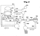
ここで図8を参照すると、ジェット流体58は、供給ライン258により、ヒーター/冷却機264に接続された、タンクまたは容器256に大量に格納される。液体化学物質源またはタンク260は、化学物質配送ライン262により、任意に液体タンク256に接続される。代替的に、化学物質供給タンク260は、ヒーター/冷却機264の下流で、液体供給ライン258に接続されてもよい。オゾン発生器72は、オゾンを液体内に供給するよう、任意に、ヒーター/冷却機264の下流で液体供給ライン258に接続している。オゾン発生器72はまた、オゾンガスを直接チャンバに供給するよう、オゾン入口206で、処理チャンバ180に接続されてもよい。
Referring now to FIG. 8, the
ヒーター/冷却機264からの液体供給ライン258は、ノズル56まで伸びる供給ライン296に流入する液体を加圧する、高圧ポンプ272に接続している。処理チャンバ180内の化学ガスポート278へ接続する化学ガス供給276は、オゾン発生器72に加えて、任意に設けられてもよい。スイングアームアセンブリ190上の蒸気ライン198に接続した、蒸気発生器またはボイラ112が設けられてもよい。
The
図12を参照すると、音波振動子203は、ホルダまたは固定具148により保持されるワークピース20に接触して、ヘッド142上に設けられてもよい。直接接触振動子203は、メガソニック振動子または超音波振動子であってもよく、さらに、ノズル56での音波振動子202の代わりに、またはそれに加えて使用されてもよい。
Referring to FIG. 12, the
同様に、ボウル166の内側表面上に支えられ、さらに蒸気発生器112に接続された蒸気ノズル201は、スイングアームアセンブリ190上の蒸気ノズル200の代わりに、またはそれに加えて使用されてもよい。加えて、UVランプなどの電磁放射源205は、ワークピース20の表面を照射するために、処理チャンバ180内に設けられてもよい。
Similarly, a
これまで述べてきた、図12に示された設計および特徴の記述は、(図13に示されたような、半径Rに沿って移動するノズルの代わりに)図11に示された直線移動ノズルを有する実施例にも適用される。同様に、以上の記述は、固定ノズル、および、実質的にワークピースの表面全体(下方の面)をジェット62にさらすよう、回転し、および移し、または処理し、またはそうでなければ移動するワークピースを有する、実施例にも適用される。
The design and feature description shown in FIG. 12 that has been described so far is the linear moving nozzle shown in FIG. 11 (instead of the nozzle moving along radius R, as shown in FIG. 13). This also applies to embodiments having Similarly, the above description will rotate and move or treat or otherwise move the fixed nozzle and substantially the entire surface of the workpiece (the lower surface) to be exposed to the
液体およびガスの化学添加物、照射源、および音波振動子は、本システムまたは方法に不可欠ではないが、若干のアプリケーションでは好ましいだろう。ヒーター/冷却機オゾン(heater/chiller ozone)、および蒸気も、多くのアプリケーションにおいて好ましいが、省略可能である。基本的特徴は、高圧液体のジェット、およびワークピース表面にわたるジェットの動きを含む。 Liquid and gas chemical additives, irradiation sources, and acoustic transducers are not essential to the system or method, but may be preferred for some applications. Heater / chiller ozone, and steam are also preferred in many applications, but can be omitted. Basic features include high pressure liquid jets and jet movement across the workpiece surface.
バルブ、メーター、フィルタ、および、流体システムの設計でよく知られている、他の標準構成要素および技術は、図示の明快さのために、図8から省略されている。 Other standard components and techniques well known in the design of valves, meters, filters, and fluid systems have been omitted from FIG. 8 for clarity of illustration.
図10を参照すると、使用に際し、ワークピース容器またはキャリヤ130は、洗浄システム121のロード/アンロード部128に移動される。ロボット132は、キャリヤ130から単一のワークピースを取り出す。ロード対象となる処理チャンバ140のヘッド142は、上向きになっている。ロボット132は、ワークピース20を、上向きヘッド142上のホルダまたは固定具148内に配置する。その後、ピボットドライブモーター164が通電され、ヘッド142を下向き位置へ(通常180°)旋回させる。その後、ヘッドエレベータ160は、ヘッド142およびワークピース20を、ヘッド142がボウル166と係合するまで下降させる。
Referring to FIG. 10, in use, the workpiece container or
図11を参照すると、ヘッド142がボウル166上に係合し、シール152により任意にシールされると、ヘッド旋回モーター146が通電されワークピース20を回転させる。供給ライン258およびポンプ272により、高圧流体が、1つ以上のノズル56へ提供される。トラックモーター172が通電され、1つ以上のノズル56を、処理チャンバ166内で直線移動させる。ワークピース20の旋回運動、および1つ以上のノズル56の直線運動により、実質的にノズル56に面するワークピース20表面全体が、高圧液体のジェット62に接触するのを確実にする。
Referring to FIG. 11, when the
図12に示された実施例の動作は、図13に示されるように、ノズル56が軸212の周りを半径R上で動くのを除いては、図11に関して上述した動作と同様である。また、図12のスイングアームアセンブリ190上の液体ジェットノズル56を伴って移動する、電磁放射源204、音波振動子194、および蒸気ノズル200(使用の場合)は、ジェットノズル56と共に動く、電磁放射線、および音波源、および蒸気源を提供するよう、図11に示された設計内の多岐管154上、またはノズル56周辺の他の構造上に設けられてもよい。
The operation of the embodiment shown in FIG. 12 is similar to the operation described above with respect to FIG. 11 except that the
ジェットノズル56は、ジェット62がワークピース20に対して垂直となるよう方向付けられるのが好ましいが、角度を有してワークピースに衝突するジェットも使用可能である。図11および図12のジェットノズルはワークピースの下方に位置決めされているが、ジェットノズルおよびワークピースは、ノズルがワークピースの鉛直上方に方向付けられていたり、または、ワークピースの一側面に方向付けられていてもよい。
The
図8、図11、および図12を参照すると、タンク256内の液体は、水、または脱イオン水であるのが好ましい。しかしながら、他の液体を、単独で、または水に混合させて用いてもよい。例えば、イソプロピルアルコール、n‐メチルピロリドン、燐酸、または硫酸、またはハロゲン化炭化水素などの有機溶媒を、水の代わりに、または水と混合させて使用してもよい。水は、ほとんどのアプリケーションにおける液体として好適である。水を用いる利点には、低コスト、および小さい環境影響、および熱容量、および多くの汚染物質の溶解能力が含まれている。
Referring to FIGS. 8, 11, and 12, the liquid in
化学物質タンク260内の液体の化学添加物は、フッ化水素酸、塩酸、水酸化アンモニウム、または過酸化水素を含んでいてもよい。フッ化水素酸および塩酸は、金属除去能力を高めることが出来る。フッ化水素酸はまた、酸化物腐食剤として働くことも出来る。アンモニウム水酸化物は溶液のpHを増加させ、それによりウエハ表面のゼータ動電位を最適化し、その結果、ウエハ表面への粒子付着可能性を減少させる。過酸化水素は、ヘキサメチルジシラザン、フォトレジスト接着促進剤などの有機物質の除去を強めるために、添加可能である。これら、および同様の液体化学物質が添加され、または単独で使用され得る一方で、上述のシステムおよび方法は、いかなる添加物も伴わない、水などの単一の液体成分を使用してもよい。 The liquid chemical additive in chemical tank 260 may include hydrofluoric acid, hydrochloric acid, ammonium hydroxide, or hydrogen peroxide. Hydrofluoric acid and hydrochloric acid can increase the metal removal ability. Hydrofluoric acid can also act as an oxide etchant. Ammonium hydroxide increases the pH of the solution, thereby optimizing the zeta dynamic potential on the wafer surface and, as a result, reducing the possibility of particle deposition on the wafer surface. Hydrogen peroxide can be added to enhance the removal of organic materials such as hexamethyldisilazane and photoresist adhesion promoters. While these and similar liquid chemicals may be added or used alone, the systems and methods described above may use a single liquid component, such as water, without any additives.
さらに図8を参照すると、液体58の加熱は、処理をスピードアップするのに有利である。液体58が水である場合、ヒーター/冷却機264は、液体58を、例えば25°‐99℃の温度に加熱するよう設定してもよく、また、液体または主要な液体成分として水を用いる場合、ヒーター/冷却機264は、液体58を、好ましくは40°‐97℃の温度に加熱するよう設定してもよい。多くのアプリケーションでは、液体58を、その沸点ぎりぎりまで加熱することが好ましい。 Still referring to FIG. 8, heating the liquid 58 is advantageous to speed up the process. If the liquid 58 is water, the heater / cooler 264 may be set to heat the liquid 58 to a temperature of, for example, 25 ° -99 ° C., and if water is used as the liquid or main liquid component The heater / cooler 264 may be set to heat the liquid 58, preferably to a temperature of 40 ° -97 ° C. For many applications, it is preferable to heat the liquid 58 to just below its boiling point.
液体ジェット62は、運動エネルギーを用いて、ワークピースから汚染物質を機械的または物理的に除去する。液体58の密度を増加させることにより、ジェット、コラム、またはビーズ62の運動エネルギーを増加させることが出来る。液体58の密度が増加するのに従い、ワークピース表面に衝突する1秒あたりの液体の質量が増加する。汚染物質を除去するために付与される、利用可能な運動エネルギーは、以下の方程式に従って増加することになる。
The
運動エネルギー=0.5×(液体の質量)×(液体の速度)2 Kinetic energy = 0.5 x (liquid mass) x (liquid velocity) 2
結果として、利用可能な運動エネルギーは、液体濃度に対して線形に増加する。ヒーター/冷却機264を用いて、液体を周囲の温度以下に冷やすことにより、液体濃度を増加させることが出来る。 As a result, the available kinetic energy increases linearly with liquid concentration. By using the heater / cooler 264 to cool the liquid below ambient temperature, the liquid concentration can be increased.
オゾン発生器72により供給されるオゾンは、液体供給ライン258へ、または、直接に、オゾンポート206で処理チャンバ166内へ、配送されてもよい。液体58がヒーター/冷却機264により加熱される場合、液体中のオゾンガス溶解度は低下する。その結果、過剰なオゾンは液体と共に流動する気泡を形成する一方で、液体供給ライン258に配送される若干のオゾンは液体内に溶解することもある。溶解したオゾンおよび液体内のオゾン気泡の双方は、存在する場合には、洗浄処理に役立つ。
Ozone supplied by the
水素ガスなどの還元剤をチャンバ180に提供するよう、化学ガス供給276が含まれていてもよい。水素ガス、または他の還元剤は、汚染物質と反応し、さらに、水内での汚染物質の溶解度を増加させることにより、汚染物質の除去を促進する。
To provide a reducing agent such as hydrogen gas in
図8および図12を参照すると、蒸気発生器112(使用される場合)は、蒸気を蒸気ノズル200および/または201に供給する。ノズルは、直接ワークピース上に、またはワークピースを横切って、蒸気をスプレーすることが好ましい。高圧液体洗浄処理の間、ワークピース表面への蒸気の同時導入は、付加的な剥離能力および洗浄能力を加える。蒸気温度は100°‐500℃まで変化可能である。ワークピース表面に衝突する蒸気の分子速度を大きくすることにより、物理的な汚染物質除去を機能させることが出来るが、高圧液体ジェットと同様の方法には、蒸気が提供する他の除去メカニズムが存在する。蒸気がワークピース表面上で凝縮するとき、凝縮熱に起因して、1グラムあたりおよそ2300ジュールのエネルギーを放出する。この追加エネルギーは、その後、ワークピース表面上の汚染物質除去の促進に利用可能である。以下の表1は、単一のウエハプラットホーム内で、様々な水/オゾン方法を用いて、シリコンウエハから厚さ2.0ミクロンのフォトレジストを除去するのに要する時間を示している。

表1に示されるように、オゾンを伴う蒸気/高圧液体(水)処理は、フォトレジストを除去するために相乗的に働く。 As shown in Table 1, vapor / high pressure liquid (water) treatment with ozone works synergistically to remove the photoresist.
さらに図8を参照すると、液体ジェット62は、ワークピースから、有機物質、金属汚染物質、および他の汚染物質を機械的に除去する。音波振動子202および/または203(使用される場合)は、ワークピースに伝えるエネルギーを増加させる。液体ジェット62がワークピースに衝突する際に、音エネルギーをワークピースに提供すると、より大きな衝撃エネルギーをもたらすことが出来る。振動子202からの、ノズル56での音エネルギーは、液体ジェット62が、実質的に圧縮不可能な液体コラムを形成する際に、ジェット62を通してワークピースに与えられる。
Still referring to FIG. 8, the
電磁放射源204および/または205(使用される場合)は、洗浄されているワークピースの表面に向かって焦点を合わせることが好ましい。ワークピースの全表面が、同時に照射されてもよい。代替的に、源204は、レンズまたは光ファイバ配送装置を用いて、ワークピース20上のジェット62の衝突点に向かって焦点を合わせてもよい。
The
図12に示された実施例では、ワークピース20の回転運動により、ノズルからのジェット62が実質的に(下方を向いた)ワークピース表面の全体に接触するよう、スイングアームアセンブリ190は、角度θ、例えば、40°‐70°の範囲で軸212上で旋回する。モーター146は、除去する汚染物質に応じて、ワークピース20を1‐5,000rpmで旋回させる。フォトレジスト除去のための好ましい旋回速度は、100‐2,000rpmの範囲で変化する。
In the embodiment shown in FIG. 12, the
高圧液体ジェット62の使用は、現行の洗浄で使用されている化学物質の量をゼロにするか、または大幅に減少させることが出来る。洗浄に高圧液体ジェットを用いることは、上述のように、ドライプラズマエッチング処理を代替し、ドライエッチプラズマ発生器の必要性を排除することも可能である。その結果、半導体、および同様のマイクロエレクトロニック装置、およびワークピースのメーカーは、製造コストを減少させ、洗浄性能を低下させることなく、その製造過程での環境影響を少なくすることが可能である。
The use of a high
フォトレジスト、粒子、有機物質、および金属を含む表面汚染を除去するための、様々なエネルギー源の組み合わせは、除去処理の有効性を増加させる。表面洗浄処理または準備処理は、環境影響の減少、コストの低減、および半導体並びに関連装置の改良された製造を伴う、化学物質消費量の観点から、より効率的に実行可能である。 The combination of various energy sources to remove surface contamination including photoresist, particles, organic materials, and metals increases the effectiveness of the removal process. The surface cleaning or preparatory process can be performed more efficiently in terms of chemical consumption, with reduced environmental impact, reduced costs, and improved manufacturing of semiconductors and related equipment.
フォトレジストは、除去される汚染物質の一例である。フォトレジストは、炭化水素化合物、または炭化水素構成を伴う重合体である。フォトレジストは、高分子化合物を溶剤と化学結合させることにより、除去されてもよい。その溶剤は、硫酸などの湿潤化学物質、または水とオゾンなどの酸化剤との混合液であってもよい。代替的に、フォトレジストは、電気的に励起された有機プラズマなどのように、適切に励起された酸素などの酸化剤との組み合わせで除去可能である。いずれの場合も、例えばフォトレジストなどの汚染物質の除去は、炭化水素を結合している結合エネルギーおよび/または機械エネルギーに打ち勝ち、それにより、分離成分が酸化剤または他の溶剤と化合可能となる必要がある。 Photoresist is an example of a contaminant that is removed. The photoresist is a hydrocarbon compound or a polymer with a hydrocarbon composition. The photoresist may be removed by chemically bonding the polymer compound with a solvent. The solvent may be a wet chemical such as sulfuric acid or a mixture of water and an oxidizing agent such as ozone. Alternatively, the photoresist can be removed in combination with a suitably excited oxidant such as oxygen, such as an electrically excited organic plasma. In either case, removal of contaminants such as photoresist, for example, overcomes the binding energy and / or mechanical energy that binds the hydrocarbons, thereby allowing the separation component to combine with an oxidant or other solvent. There is a need.
水の使用は、有機分子の炭素‐炭素結合を加水分解し、またはH‐C重合体と化合させるよう機能し、さらに炭化水素との、および炭化水素間の若干の結合エネルギーを除去するよう機能する。水はまた、シリコン‐水素結合、またはシリコン‐水酸基結合を加水分解することにより、シリコン表面の酸化を加速する。水に添加して酸化剤を用いることにより、酸化剤の有効性が増加する。レジスト処置がホウ素や砒素のような、シリコン内への埋込みに用いられる、著しく強く帯電された媒体の露光を含む場合、レジストは、架橋結合または緊密結合となる。この場合、オゾンおよび水などのさほど攻撃的でない媒体の使用は、フォトレジストの除去に十分でない場合がある。しかしながら、架橋現象に起因して程度は低くなるものの、ある程度の攻撃または酸化が行われる。結果として、除去の有効性を増加させるよう、追加形式のエネルギー(音エネルギー、電磁エネルギー、熱エネルギー、および/または機械エネルギー)を併用することが有利である。メガソニックまたは超音波の使用は、音エネルギーの例であり、UVは電磁エネルギーの例である。高圧スプレーは機械エネルギーの例である。熱エネルギーは、蒸気、赤外線加熱、またはワークピースの温度を上げる他の手段の形で、取り入れ可能である。 The use of water functions to hydrolyze or combine the carbon-carbon bonds of organic molecules with HC polymers and to remove some binding energy with and between hydrocarbons. To do. Water also accelerates oxidation of the silicon surface by hydrolyzing silicon-hydrogen bonds or silicon-hydroxyl bonds. Addition to water and the use of an oxidant increases the effectiveness of the oxidant. If the resist treatment involves exposure of a significantly strongly charged medium used for implantation in silicon, such as boron or arsenic, the resist becomes cross-linked or tightly bonded. In this case, the use of less aggressive media such as ozone and water may not be sufficient to remove the photoresist. However, some attack or oxidation is performed, although to a lesser extent due to the cross-linking phenomenon. As a result, it is advantageous to combine additional forms of energy (sound energy, electromagnetic energy, thermal energy, and / or mechanical energy) to increase the effectiveness of removal. The use of megasonics or ultrasound is an example of sound energy and UV is an example of electromagnetic energy. High pressure spray is an example of mechanical energy. Thermal energy can be incorporated in the form of steam, infrared heating, or other means of raising the temperature of the workpiece.
これらのエネルギー源の2つ以上の併用により、汚染除去のための新規な技術が提供される。例えば、熱エネルギーを赤外線エネルギーの形で、オゾンおよび水と併用すると、酸化剤を供給しながら、同時にワークピースまたはウエハの表面での温度を上昇させる。高圧水を、オゾンおよびアンモニアなどの化学物質と組合せて用いることにより、汚染またはフォトレジストを生成する、相補的エネルギー源の組合せを提供する。 The combination of two or more of these energy sources provides a new technique for decontamination. For example, when heat energy is used in combination with ozone and water in the form of infrared energy, the temperature at the surface of the workpiece or wafer is increased while supplying the oxidant. High pressure water is used in combination with chemicals such as ozone and ammonia to provide a complementary energy source combination that produces contamination or photoresist.
14 洗浄システム、15 処理チャンバ、20 ワークピース、25 サポート、30 ローターアセンブリ、37 スピン軸、40 ノズル、45 貯蔵層、55 ポンプ、60 流体流路、65 フィルタ、70 流体流動ライン。
14 cleaning system, 15 processing chamber, 20 workpiece, 25 support, 30 rotor assembly, 37 spin axis, 40 nozzle, 45 reservoir, 55 pump, 60 fluid flow path, 65 filter, 70 fluid flow line.
Claims (18)
ワークピースの表面上に加熱された液体の層を形成するステップと、
加熱された液体の層の厚みを制御するステップと、
オゾンガスをワークピースの周りに提供して、オゾンガスを加熱された液体の層に拡散させ、ワークピースの表面上にある汚染物質と化学的に反応させるステップと、
液体のジェットをワークピースの表面に噴射して、液体のジェットを加熱された液体の層を貫通させ、ワークピースの表面に衝突させて、ワークピースの表面上にある汚染物質を物理的に除去するステップとを有することを特徴とする方法。 A method of cleaning a workpiece,
Forming a layer of heated liquid on the surface of the workpiece;
Controlling the thickness of the heated liquid layer;
Providing ozone gas around the workpiece to diffuse the ozone gas into the heated liquid layer and chemically react with contaminants on the surface of the workpiece;
A liquid jet is sprayed onto the surface of the workpiece, causing the liquid jet to penetrate the heated liquid layer and impinge on the workpiece surface to physically remove contaminants on the workpiece surface. Comprising the steps of :
処理チャンバと、
1つまたは複数のワークピースを保持するためのチャンバ内の固定具と、
ワークピースの周りにオゾンを提供するためのオゾン源と、
ワークピースの表面上に形成された加熱された液体の層の厚みを制御して、オゾンガスを加熱された液体の層に拡散させ、ワークピースの表面上にある汚染物質と化学的に反応させる手段と、
処理チャンバ内に設けられ、液体のジェットをワークピースの表面に噴射するための少なくとも1つのジェットノズルとを備え、
液体のジェットが加熱された液体の層を貫通し、ワークピースの表面に衝突して、ワークピースの表面上にある汚染物質を物理的に除去することを特徴とする装置。 An apparatus for removing contaminants from a workpiece,
A processing chamber;
A fixture in the chamber for holding one or more workpieces;
An ozone source to provide ozone around the workpiece;
Means for controlling the thickness of the heated liquid layer formed on the surface of the workpiece to diffuse ozone gas into the heated liquid layer and chemically react with contaminants on the surface of the workpiece When,
At least one jet nozzle provided in the processing chamber for injecting a jet of liquid onto the surface of the workpiece;
An apparatus wherein a jet of liquid penetrates a heated layer of liquid and strikes the surface of the workpiece to physically remove contaminants on the surface of the workpiece .
ワークピースの表面上に加熱された液体の層を形成するステップと、Forming a layer of heated liquid on the surface of the workpiece;
加熱された液体の層の厚みを制御するステップと、Controlling the thickness of the heated liquid layer;
オゾンガスをワークピースの周りに提供して、オゾンガスを加熱された液体の層に拡散させ、ワークピースの表面上にある汚染物質と化学的に反応させるステップと、Providing ozone gas around the workpiece to diffuse the ozone gas into the heated liquid layer and chemically react with contaminants on the surface of the workpiece;
蒸気のジェットをワークピースの表面に噴射して、蒸気のジェットを加熱された液体の層を貫通させ、ワークピースの表面に衝突させて、ワークピースの表面上にある汚染物質を物理的に除去するステップとを有することを特徴とする方法。A jet of vapor is sprayed onto the surface of the workpiece, causing the vapor jet to penetrate the heated liquid layer and impinge on the workpiece surface to physically remove contaminants on the workpiece surface. Comprising the steps of:
Applications Claiming Priority (2)
| Application Number | Priority Date | Filing Date | Title |
|---|---|---|---|
| US09/925,884 US20020157686A1 (en) | 1997-05-09 | 2001-08-06 | Process and apparatus for treating a workpiece such as a semiconductor wafer |
| PCT/US2002/023515 WO2003015146A1 (en) | 2001-08-06 | 2002-07-23 | Process and apparatus for treating a workpiece such as a semiconductor wafer |
Publications (3)
| Publication Number | Publication Date |
|---|---|
| JP2004538635A JP2004538635A (en) | 2004-12-24 |
| JP2004538635A5 JP2004538635A5 (en) | 2005-12-22 |
| JP3977807B2 true JP3977807B2 (en) | 2007-09-19 |
Family
ID=25452388
Family Applications (1)
| Application Number | Title | Priority Date | Filing Date |
|---|---|---|---|
| JP2003519981A Expired - Fee Related JP3977807B2 (en) | 2001-08-06 | 2002-07-23 | Processing and equipment for handling workpieces such as semiconductor wafers |
Country Status (9)
| Country | Link |
|---|---|
| US (2) | US20020157686A1 (en) |
| EP (1) | EP1421609B1 (en) |
| JP (1) | JP3977807B2 (en) |
| KR (1) | KR20040035721A (en) |
| CN (1) | CN1319131C (en) |
| AT (1) | ATE390706T1 (en) |
| DE (1) | DE60225817T2 (en) |
| TW (1) | TW559940B (en) |
| WO (1) | WO2003015146A1 (en) |
Families Citing this family (115)
| Publication number | Priority date | Publication date | Assignee | Title |
|---|---|---|---|---|
| US7404863B2 (en) * | 1997-05-09 | 2008-07-29 | Semitool, Inc. | Methods of thinning a silicon wafer using HF and ozone |
| US20050194356A1 (en) * | 1997-05-09 | 2005-09-08 | Semitool, Inc. | Removing photoresist from a workpiece using water and ozone and a photoresist penetrating additive |
| US6758938B1 (en) * | 1999-08-31 | 2004-07-06 | Micron Technology, Inc. | Delivery of dissolved ozone |
| US6774056B2 (en) | 1999-11-10 | 2004-08-10 | Semitool, Inc. | Sonic immersion process system and methods |
| WO2002027775A1 (en) * | 2000-09-28 | 2002-04-04 | Mitsubishi Denki Kabushiki Kaisha | Method and apparatus for treating wafer |
| US20080000495A1 (en) * | 2001-12-07 | 2008-01-03 | Eric Hansen | Apparatus and method for single substrate processing |
| US6726848B2 (en) * | 2001-12-07 | 2004-04-27 | Scp Global Technologies, Inc. | Apparatus and method for single substrate processing |
| US20070079932A1 (en) * | 2001-12-07 | 2007-04-12 | Applied Materials, Inc. | Directed purge for contact free drying of wafers |
| US20090029560A1 (en) * | 2001-12-07 | 2009-01-29 | Applied Materials, Inc. | Apparatus and method for single substrate processing |
| JP3979464B2 (en) * | 2001-12-27 | 2007-09-19 | 株式会社荏原製作所 | Electroless plating pretreatment apparatus and method |
| US6955485B2 (en) * | 2002-03-01 | 2005-10-18 | Tokyo Electron Limited | Developing method and developing unit |
| US20030192570A1 (en) * | 2002-04-11 | 2003-10-16 | Applied Materials, Inc. | Method and apparatus for wafer cleaning |
| US20030192577A1 (en) * | 2002-04-11 | 2003-10-16 | Applied Materials, Inc. | Method and apparatus for wafer cleaning |
| US6848455B1 (en) * | 2002-04-22 | 2005-02-01 | Novellus Systems, Inc. | Method and apparatus for removing photoresist and post-etch residue from semiconductor substrates by in-situ generation of oxidizing species |
| US20040159335A1 (en) * | 2002-05-17 | 2004-08-19 | P.C.T. Systems, Inc. | Method and apparatus for removing organic layers |
| WO2004021420A2 (en) * | 2002-08-29 | 2004-03-11 | Massachusetts Institute Of Technology | Fabrication method for a monocrystalline semiconductor layer on a substrate |
| JPWO2004027849A1 (en) * | 2002-09-20 | 2006-01-19 | 株式会社日立国際電気 | Semiconductor device manufacturing method and substrate processing apparatus |
| ATE353475T1 (en) * | 2002-10-11 | 2007-02-15 | Soitec Silicon On Insulator | METHOD AND DEVICE FOR PRODUCING AN ADHESIVE SUBSTRATE SURFACE |
| US7022193B2 (en) * | 2002-10-29 | 2006-04-04 | In Kwon Jeong | Apparatus and method for treating surfaces of semiconductor wafers using ozone |
| US7163018B2 (en) * | 2002-12-16 | 2007-01-16 | Applied Materials, Inc. | Single wafer cleaning method to reduce particle defects on a wafer surface |
| US6960921B2 (en) | 2003-03-14 | 2005-11-01 | Steris Inc. | Method and apparatus for real time monitoring of metallic cation concentrations in a solution |
| US6946852B2 (en) * | 2003-03-14 | 2005-09-20 | Steris Inc. | Method and apparatus for measuring concentration of a chemical component in a gas mixture |
| US6897661B2 (en) * | 2003-03-14 | 2005-05-24 | Steris Inc. | Method and apparatus for detection of contaminants in a fluid |
| US6930493B2 (en) * | 2003-03-14 | 2005-08-16 | Steris Inc. | Method and apparatus for monitoring detergent concentration in a decontamination process |
| US6992494B2 (en) * | 2003-03-14 | 2006-01-31 | Steris Inc. | Method and apparatus for monitoring the purity and/or quality of steam |
| US6927582B2 (en) * | 2003-03-14 | 2005-08-09 | Steris Inc. | Method and apparatus for monitoring the state of a chemical solution for decontamination of chemical and biological warfare agents |
| US6933733B2 (en) | 2003-03-14 | 2005-08-23 | Steris Inc. | Method and apparatus for measuring the concentration of hydrogen peroxide in a fluid |
| WO2004112093A2 (en) | 2003-06-06 | 2004-12-23 | P.C.T. Systems, Inc. | Method and apparatus to process substrates with megasonic energy |
| US6909972B2 (en) * | 2003-06-06 | 2005-06-21 | Steris Inc. | Method and apparatus for formulating and controlling chemical concentrations in a solution |
| US6917885B2 (en) * | 2003-06-06 | 2005-07-12 | Steris Inc. | Method and apparatus for formulating and controlling chemical concentration in a gas mixture |
| TWI377453B (en) * | 2003-07-31 | 2012-11-21 | Akrion Technologies Inc | Process sequence for photoresist stripping and/or cleaning of photomasks for integrated circuit manufacturing |
| AT501775B1 (en) * | 2003-12-18 | 2009-01-15 | Tokyo Electron Ltd | METHOD FOR REMOVING A RESIST FILM, SUBSTRATE TREATMENT DEVICE AND COMPUTER-READABLE RECORDING MEDIUM |
| TWI282586B (en) * | 2004-02-24 | 2007-06-11 | Innolux Display Corp | Etching system and de-ion water adding set |
| SE525971C2 (en) * | 2004-03-08 | 2005-06-07 | Scania Cv Abp | Equipment is for conditioning an object which is supported by a handling device between treatment stages during a production process |
| US7337663B2 (en) * | 2004-03-12 | 2008-03-04 | Semitool, Inc. | Sonic energy process chamber |
| FR2868599B1 (en) * | 2004-03-30 | 2006-07-07 | Soitec Silicon On Insulator | OPTIMIZED SC1 CHEMICAL TREATMENT FOR CLEANING PLATELETS OF SEMICONDUCTOR MATERIAL |
| US7448395B2 (en) * | 2004-07-19 | 2008-11-11 | Texas Instruments Incorporated | Process method to facilitate silicidation |
| US7431886B2 (en) * | 2004-09-24 | 2008-10-07 | Steris Corporation | Method of monitoring operational status of sensing devices for determining the concentration of chemical components in a fluid |
| JP4407944B2 (en) * | 2004-12-21 | 2010-02-03 | 大日本スクリーン製造株式会社 | Substrate processing apparatus and substrate processing method |
| KR20060072498A (en) * | 2004-12-23 | 2006-06-28 | 동부일렉트로닉스 주식회사 | Semiconductor device and fabrication method thereof |
| JP4553939B2 (en) * | 2005-06-28 | 2010-09-29 | カナン精機株式会社 | Surface-modified member, surface treatment method and surface treatment apparatus |
| US20070068558A1 (en) * | 2005-09-06 | 2007-03-29 | Applied Materials, Inc. | Apparatus and methods for mask cleaning |
| CN101900956A (en) | 2005-11-23 | 2010-12-01 | Fsi国际公司 | Remove the method for material from base material |
| KR101079323B1 (en) | 2005-12-21 | 2011-11-04 | 주식회사 엘지실트론 | System for cleaning wafer using ozone |
| US8480810B2 (en) * | 2005-12-30 | 2013-07-09 | Lam Research Corporation | Method and apparatus for particle removal |
| SG154438A1 (en) * | 2005-12-30 | 2009-08-28 | Lam Res Corp | Cleaning compound and method and system for using the cleaning compound |
| US7849916B2 (en) * | 2006-02-02 | 2010-12-14 | Noah Precision, Llc | Temperature control apparatus and method |
| CN101389415A (en) * | 2006-02-22 | 2009-03-18 | 赛迈有限公司 | Single side workpiece processing |
| GB2436453A (en) * | 2006-03-24 | 2007-09-26 | Mecwash Systems Ltd | An aqueous washing system and method |
| US20080029123A1 (en) * | 2006-08-02 | 2008-02-07 | Brian Aegerter | Sonic and chemical wafer processor |
| US20080057678A1 (en) * | 2006-08-31 | 2008-03-06 | Kishor Purushottam Gadkaree | Semiconductor on glass insulator made using improved hydrogen reduction process |
| US20080060683A1 (en) * | 2006-09-08 | 2008-03-13 | Arvidson Aaron W | Apparatus and methods for cleaning a wafer edge |
| US8741066B2 (en) | 2007-02-16 | 2014-06-03 | Akrion Systems, Llc | Method for cleaning substrates utilizing surface passivation and/or oxide layer growth to protect from pitting |
| US7819984B2 (en) * | 2007-05-18 | 2010-10-26 | Fsi International, Inc. | Process for treatment of substrates with water vapor or steam |
| DE102007027112B4 (en) * | 2007-06-13 | 2011-06-22 | Siltronic AG, 81737 | Process for cleaning, drying and hydrophilizing a semiconductor wafer |
| KR100895861B1 (en) * | 2007-10-04 | 2009-05-06 | 세메스 주식회사 | Method for treating process solution and Apparatus for treating a substrate |
| US7846262B2 (en) * | 2007-11-08 | 2010-12-07 | Gray Donald J | Aqueous cleaning of liquid residue by etching |
| JP5152851B2 (en) * | 2008-04-17 | 2013-02-27 | 国立大学法人東北大学 | Manufacturing method of semiconductor device |
| WO2009139816A1 (en) * | 2008-05-15 | 2009-11-19 | Fsi International, Inc. | Process for treatment of semiconductor wafer using water vapor containing environment |
| DE102008048540A1 (en) * | 2008-09-15 | 2010-04-15 | Gebr. Schmid Gmbh & Co. | Process for the treatment of substrates, substrate and treatment device for carrying out the method |
| US20100124410A1 (en) * | 2008-11-18 | 2010-05-20 | Fsi International, Inc. | System for supplying water vapor in semiconductor wafer treatment |
| WO2010140581A1 (en) * | 2009-06-03 | 2010-12-09 | 倉敷紡績株式会社 | Method for supplying hydroxyl radical-containing water and apparatus for supplying hydroxyl radical-containing water |
| US8584612B2 (en) * | 2009-12-17 | 2013-11-19 | Lam Research Corporation | UV lamp assembly of degas chamber having rotary shutters |
| CN102476108A (en) * | 2010-11-23 | 2012-05-30 | 中国科学院微电子研究所 | High-temperature vapor-water mixed jet cleaning system and method |
| EP2515323B1 (en) * | 2011-04-21 | 2014-03-19 | Imec | Method and apparatus for cleaning semiconductor substrates |
| US9221081B1 (en) | 2011-08-01 | 2015-12-29 | Novellus Systems, Inc. | Automated cleaning of wafer plating assembly |
| US10066311B2 (en) | 2011-08-15 | 2018-09-04 | Lam Research Corporation | Multi-contact lipseals and associated electroplating methods |
| US9988734B2 (en) | 2011-08-15 | 2018-06-05 | Lam Research Corporation | Lipseals and contact elements for semiconductor electroplating apparatuses |
| US9228270B2 (en) | 2011-08-15 | 2016-01-05 | Novellus Systems, Inc. | Lipseals and contact elements for semiconductor electroplating apparatuses |
| WO2013086217A1 (en) | 2011-12-06 | 2013-06-13 | Masco Corporation Of Indiana | Ozone distribution in a faucet |
| KR102112881B1 (en) * | 2012-03-28 | 2020-05-19 | 노벨러스 시스템즈, 인코포레이티드 | Methods and apparatuses for cleaning electroplating substrate holders |
| US9476139B2 (en) | 2012-03-30 | 2016-10-25 | Novellus Systems, Inc. | Cleaning electroplating substrate holders using reverse current deplating |
| KR101992422B1 (en) * | 2012-08-14 | 2019-06-24 | 주식회사 동진쎄미켐 | Apparatus and method for polishing metal layer using photolysis advanced oxidation process |
| JP2014067864A (en) * | 2012-09-26 | 2014-04-17 | Tokyo Electron Ltd | Substrate cleaning apparatus and substrate cleaning method |
| US9735026B2 (en) * | 2012-11-27 | 2017-08-15 | Tokyo Electron Limited | Controlling cleaning of a layer on a substrate using nozzles |
| US8871108B2 (en) | 2013-01-22 | 2014-10-28 | Tel Fsi, Inc. | Process for removing carbon material from substrates |
| US9746427B2 (en) | 2013-02-15 | 2017-08-29 | Novellus Systems, Inc. | Detection of plating on wafer holding apparatus |
| US10416092B2 (en) | 2013-02-15 | 2019-09-17 | Lam Research Corporation | Remote detection of plating on wafer holding apparatus |
| TWI582835B (en) * | 2013-06-07 | 2017-05-11 | 聯華電子股份有限公司 | Semiconductor fabrication equipment having assistant monitor |
| US20150007856A1 (en) * | 2013-07-08 | 2015-01-08 | David Jackson | Method for treating a substrate surface using ozonated solvent and ultraviolet light |
| US10343193B2 (en) * | 2014-02-24 | 2019-07-09 | The Boeing Company | System and method for surface cleaning |
| JP2016051727A (en) * | 2014-08-28 | 2016-04-11 | 東京エレクトロン株式会社 | Substrate processing method, substrate processing apparatus and storage medium |
| US10053793B2 (en) | 2015-07-09 | 2018-08-21 | Lam Research Corporation | Integrated elastomeric lipseal and cup bottom for reducing wafer sticking |
| TWI638383B (en) * | 2015-07-15 | 2018-10-11 | 美商原備有限公司 | Method for processing the surface of a workpiece |
| TWI629720B (en) * | 2015-09-30 | 2018-07-11 | 東京威力科創股份有限公司 | Method and apparatus for dynamic control of the temperature of a wet etch process |
| US11458214B2 (en) | 2015-12-21 | 2022-10-04 | Delta Faucet Company | Fluid delivery system including a disinfectant device |
| KR102100757B1 (en) * | 2016-04-01 | 2020-04-14 | 주식회사 뉴파워 프라즈마 | Steam generation apparatus using induction heating, steam cleaning system |
| KR102637827B1 (en) * | 2016-09-06 | 2024-02-19 | 주식회사 케이씨텍 | Substrate procesing system |
| CN107820638A (en) * | 2016-10-25 | 2018-03-20 | 深圳市柔宇科技有限公司 | Liquid temperature control system and film layer peel-off device |
| JP7297664B2 (en) | 2016-11-09 | 2023-06-26 | ティーイーエル マニュファクチュアリング アンド エンジニアリング オブ アメリカ,インコーポレイテッド | Magnetically Levitating and Rotating Chuck for Processing Microelectronic Substrates in Process Chambers |
| TWI765936B (en) | 2016-11-29 | 2022-06-01 | 美商東京威力科創Fsi股份有限公司 | Translating and rotating chuck for processing microelectronic substrates in a process chamber |
| CN108242414A (en) * | 2016-12-27 | 2018-07-03 | 中国科学院微电子研究所 | A kind of processing method and processing device of semiconductor chip |
| JP7177069B2 (en) * | 2017-01-27 | 2022-11-22 | ティーイーエル マニュファクチュアリング アンド エンジニアリング オブ アメリカ,インコーポレイテッド | Systems and methods for rotating and translating a substrate within a process chamber |
| KR102370369B1 (en) * | 2017-05-26 | 2022-03-04 | 인제대학교 산학협력단 | Solution process apparatus using microwave and nebulizer |
| TWI739958B (en) * | 2017-11-21 | 2021-09-21 | 聯華電子股份有限公司 | Method for adjusting surface uniformity of wafer |
| DE102017221530A1 (en) * | 2017-11-30 | 2019-06-06 | Robert Bosch Gmbh | Device designed for environment detection and method for cleaning a cover of such a device |
| CN108323112B (en) * | 2018-02-10 | 2023-09-15 | 中国电子科技集团公司第十六研究所 | Synthetic jet liquid cooling device |
| TW201939572A (en) | 2018-02-19 | 2019-10-01 | 美商東京威力科創Fsi股份有限公司 | Microelectronic treatment system having treatment spray with controllable beam size |
| CN108372162A (en) * | 2018-02-27 | 2018-08-07 | 宿宏 | A kind of separation gel blocks the processing method of medical laboratory's testing instruments Measurement channel |
| US11545387B2 (en) | 2018-07-13 | 2023-01-03 | Tel Manufacturing And Engineering Of America, Inc. | Magnetic integrated lift pin system for a chemical processing chamber |
| KR102461911B1 (en) * | 2018-07-13 | 2022-10-31 | 삼성전자주식회사 | Plasma generator, cleaning liquid processing apparatus, semiconductor cleaning apparatus and cleaning liquid processing method |
| CN109107974B (en) * | 2018-07-20 | 2020-08-11 | 横店集团东磁股份有限公司 | Cleaning method of quartz device for solar cell preparation |
| JP7245059B2 (en) * | 2019-01-24 | 2023-03-23 | 株式会社ジェイ・イー・ティ | SUBSTRATE PROCESSING APPARATUS AND SUBSTRATE PROCESSING METHOD |
| KR20200092530A (en) * | 2019-01-24 | 2020-08-04 | 삼성전자주식회사 | Apparatus for removing photoresists and method of manufacturing semiconductor device by using the same |
| JP7202230B2 (en) * | 2019-03-20 | 2023-01-11 | 株式会社Screenホールディングス | Substrate processing method and substrate processing apparatus |
| TW202110575A (en) * | 2019-05-29 | 2021-03-16 | 美商應用材料股份有限公司 | Steam treatment stations for chemical mechanical polishing system |
| CN111112215A (en) * | 2019-12-31 | 2020-05-08 | 中威新能源(成都)有限公司 | Method for cleaning silicon wafer by using alkaline solution containing ozone |
| CN111151489A (en) * | 2019-12-31 | 2020-05-15 | 中威新能源(成都)有限公司 | Method for cleaning silicon wafer in spraying mode through ozone |
| US11813649B2 (en) | 2020-05-29 | 2023-11-14 | Taiwan Semiconductor Manufacturing Company Limited | Semiconductor arrangement and method for making |
| CN116745884A (en) * | 2020-11-09 | 2023-09-12 | 伊利诺伊大学评议会 | plasma activated liquid |
| US11673830B2 (en) * | 2020-11-11 | 2023-06-13 | Applied Materials, Inc. | Glass carrier cleaning using ozone |
| US20220184771A1 (en) * | 2020-12-14 | 2022-06-16 | Applied Materials, Inc. | Polishing system apparatus and methods for defect reduction at a substrate edge |
| KR102523437B1 (en) * | 2020-12-29 | 2023-04-18 | 세메스 주식회사 | Apparatus and method for processing substrate |
| CN113690131A (en) * | 2021-10-27 | 2021-11-23 | 广州粤芯半导体技术有限公司 | Wet cleaning process |
| US11798802B2 (en) | 2022-02-11 | 2023-10-24 | Globalwafers Co., Ltd. | Methods for stripping and cleaning semiconductor structures |
Family Cites Families (101)
| Publication number | Priority date | Publication date | Assignee | Title |
|---|---|---|---|---|
| US4186032A (en) * | 1976-09-23 | 1980-01-29 | Rca Corp. | Method for cleaning and drying semiconductors |
| US4064885A (en) * | 1976-10-26 | 1977-12-27 | Branson Ultrasonics Corporation | Apparatus for cleaning workpieces by ultrasonic energy |
| JPS60210840A (en) * | 1984-03-06 | 1985-10-23 | Fujitsu Ltd | Spinning proccessor |
| US4911761A (en) * | 1984-05-21 | 1990-03-27 | Cfm Technologies Research Associates | Process and apparatus for drying surfaces |
| US4778532A (en) * | 1985-06-24 | 1988-10-18 | Cfm Technologies Limited Partnership | Process and apparatus for treating wafers with process fluids |
| US4695327A (en) * | 1985-06-13 | 1987-09-22 | Purusar Corporation | Surface treatment to remove impurities in microrecesses |
| US4749440A (en) * | 1985-08-28 | 1988-06-07 | Fsi Corporation | Gaseous process and apparatus for removing films from substrates |
| US4694327A (en) * | 1986-03-28 | 1987-09-15 | Rca Corporation | Digital phase locked loop stabilization circuitry using a secondary digital phase locked loop |
| US4817652A (en) * | 1987-03-26 | 1989-04-04 | Regents Of The University Of Minnesota | System for surface and fluid cleaning |
| US5105556A (en) * | 1987-08-12 | 1992-04-21 | Hitachi, Ltd. | Vapor washing process and apparatus |
| US5235995A (en) * | 1989-03-27 | 1993-08-17 | Semitool, Inc. | Semiconductor processor apparatus with dynamic wafer vapor treatment and particulate volatilization |
| US5181985A (en) * | 1988-06-01 | 1993-01-26 | Wacker-Chemitronic Gesellschaft Fur Elektronik-Grundstoffe Mbh | Process for the wet-chemical surface treatment of semiconductor wafers |
| DE68928010T2 (en) * | 1988-07-08 | 1997-11-20 | Rhone Poulenc Chimie | Cleaning and drying of electronic components |
| US4980032A (en) * | 1988-08-12 | 1990-12-25 | Alameda Instruments, Inc. | Distillation method and apparatus for reprocessing sulfuric acid |
| US5158100A (en) * | 1989-05-06 | 1992-10-27 | Dainippon Screen Mfg. Co., Ltd. | Wafer cleaning method and apparatus therefor |
| US5246526A (en) * | 1989-06-29 | 1993-09-21 | Hitachi, Ltd. | Surface treatment apparatus |
| FI84764C (en) * | 1989-09-25 | 1992-01-10 | Labsystems Oy | SPOLNINGSANORDNING. |
| US5063609A (en) * | 1989-10-11 | 1991-11-05 | Applied Materials, Inc. | Steam generator |
| US4974530A (en) * | 1989-11-16 | 1990-12-04 | Energy And Environmental Research | Apparatus and methods for incineration of toxic organic compounds |
| US5232511A (en) * | 1990-05-15 | 1993-08-03 | Semitool, Inc. | Dynamic semiconductor wafer processing using homogeneous mixed acid vapors |
| US5039349A (en) * | 1990-05-18 | 1991-08-13 | Veriflo Corporation | Method and apparatus for cleaning surfaces to absolute or near-absolute cleanliness |
| JPH0719739B2 (en) * | 1990-09-10 | 1995-03-06 | 信越半導体株式会社 | Bonded wafer manufacturing method |
| US5071485A (en) * | 1990-09-11 | 1991-12-10 | Fusion Systems Corporation | Method for photoresist stripping using reverse flow |
| US5832177A (en) * | 1990-10-05 | 1998-11-03 | Fujitsu Limited | Method for controlling apparatus for supplying steam for ashing process |
| US5378317A (en) * | 1990-10-09 | 1995-01-03 | Chlorine Engineers Corp., Ltd. | Method for removing organic film |
| JP2583152B2 (en) * | 1990-11-06 | 1997-02-19 | 大日本スクリーン製造株式会社 | Substrate rotating surface treatment method |
| US5261966A (en) * | 1991-01-28 | 1993-11-16 | Kabushiki Kaisha Toshiba | Method of cleaning semiconductor wafers using mixer containing a bundle of gas permeable hollow yarns |
| US5120370A (en) * | 1991-04-01 | 1992-06-09 | Shinichi Mori | Cleaning process |
| WO1992022084A1 (en) * | 1991-05-21 | 1992-12-10 | Advantage Production Technology, Inc. | Organic preclean for improving vapor phase wafer etch uniformity |
| JP3154814B2 (en) * | 1991-06-28 | 2001-04-09 | 株式会社東芝 | Semiconductor wafer cleaning method and cleaning apparatus |
| US5147499A (en) * | 1991-07-24 | 1992-09-15 | Applied Materials, Inc. | Process for removal of residues remaining after etching polysilicon layer in formation of integrated circuit structure |
| US5326406A (en) * | 1991-07-31 | 1994-07-05 | Kawasaki Steel Corporation | Method of cleaning semiconductor substrate and apparatus for carrying out the same |
| US5244000A (en) * | 1991-11-13 | 1993-09-14 | Hughes Aircraft Company | Method and system for removing contaminants |
| JPH05152203A (en) * | 1991-11-29 | 1993-06-18 | Chlorine Eng Corp Ltd | Method and device for treating substrate |
| TW263531B (en) * | 1992-03-11 | 1995-11-21 | Mitsubishi Gas Chemical Co | |
| US5234540A (en) * | 1992-04-30 | 1993-08-10 | Submicron Systems, Inc. | Process for etching oxide films in a sealed photochemical reactor |
| JPH06168922A (en) * | 1992-06-25 | 1994-06-14 | Texas Instr Inc <Ti> | Vapor etching method of silicon |
| US5366757A (en) * | 1992-10-30 | 1994-11-22 | International Business Machines Corporation | In situ resist control during spray and spin in vapor |
| US5308745A (en) * | 1992-11-06 | 1994-05-03 | J. T. Baker Inc. | Alkaline-containing photoresist stripping compositions producing reduced metal corrosion with cross-linked or hardened resist resins |
| KR940012061A (en) * | 1992-11-27 | 1994-06-22 | 가나이 쯔또무 | Organic matter removal method and organic matter removal apparatus for using the method |
| SG130022A1 (en) * | 1993-03-25 | 2007-03-20 | Tokyo Electron Ltd | Method of forming coating film and apparatus therefor |
| US5922624A (en) * | 1993-05-13 | 1999-07-13 | Imec Vzw | Method for semiconductor processing using mixtures of HF and carboxylic acid |
| JP3347814B2 (en) * | 1993-05-17 | 2002-11-20 | 大日本スクリーン製造株式会社 | Substrate cleaning / drying processing method and processing apparatus |
| US5447640A (en) * | 1993-06-28 | 1995-09-05 | Permelec Electrode Ltd. | Method and apparatus for sterilization of and treatment with ozonized water |
| US5464480A (en) * | 1993-07-16 | 1995-11-07 | Legacy Systems, Inc. | Process and apparatus for the treatment of semiconductor wafers in a fluid |
| US5911837A (en) * | 1993-07-16 | 1999-06-15 | Legacy Systems, Inc. | Process for treatment of semiconductor wafers in a fluid |
| JPH0747377A (en) * | 1993-08-06 | 1995-02-21 | Permelec Electrode Ltd | Method for treating ozone water and device therefor |
| US5730806A (en) * | 1993-08-30 | 1998-03-24 | The United States Of America As Represented By The Administrator Of The National Aeronautics & Space Administration | Gas-liquid supersonic cleaning and cleaning verification spray system |
| US5518542A (en) * | 1993-11-05 | 1996-05-21 | Tokyo Electron Limited | Double-sided substrate cleaning apparatus |
| JP3080834B2 (en) * | 1994-03-30 | 2000-08-28 | 株式会社東芝 | Semiconductor substrate cleaning equipment |
| JP3320549B2 (en) * | 1994-04-26 | 2002-09-03 | 岩手東芝エレクトロニクス株式会社 | Film removing method and film removing agent |
| JP2760418B2 (en) * | 1994-07-29 | 1998-05-28 | 住友シチックス株式会社 | Semiconductor wafer cleaning solution and method for cleaning semiconductor wafer using the same |
| US5647386A (en) * | 1994-10-04 | 1997-07-15 | Entropic Systems, Inc. | Automatic precision cleaning apparatus with continuous on-line monitoring and feedback |
| DE19522525A1 (en) * | 1994-10-04 | 1996-04-11 | Kunze Concewitz Horst Dipl Phy | Method and device for fine cleaning of surfaces |
| US5967156A (en) * | 1994-11-07 | 1999-10-19 | Krytek Corporation | Processing a surface |
| JPH08162425A (en) * | 1994-12-06 | 1996-06-21 | Mitsubishi Electric Corp | Manufacture and manufacturing method of semiconductor integrated circuit device |
| JPH08238463A (en) * | 1995-03-03 | 1996-09-17 | Ebara Corp | Cleaning method and cleaning apparatus |
| JP3923097B2 (en) * | 1995-03-06 | 2007-05-30 | 忠弘 大見 | Cleaning device |
| US5706842A (en) * | 1995-03-29 | 1998-01-13 | The United States Of America As Represented By The Administrator Of The National Aeronautics And Space Administration | Balanced rotating spray tank and pipe cleaning and cleanliness verification system |
| JP3337870B2 (en) * | 1995-05-11 | 2002-10-28 | 大日本スクリーン製造株式会社 | Rotary substrate cleaning equipment |
| US5714203A (en) * | 1995-08-23 | 1998-02-03 | Ictop Entwicklungs Gmbh | Procedure for the drying of silicon |
| JPH0969509A (en) * | 1995-09-01 | 1997-03-11 | Matsushita Electron Corp | Cleaning/etching/drying system for semiconductor wafer and using method thereof |
| US5950643A (en) * | 1995-09-06 | 1999-09-14 | Miyazaki; Takeshiro | Wafer processing system |
| US6239038B1 (en) * | 1995-10-13 | 2001-05-29 | Ziying Wen | Method for chemical processing semiconductor wafers |
| US5975098A (en) * | 1995-12-21 | 1999-11-02 | Dainippon Screen Mfg. Co., Ltd. | Apparatus for and method of cleaning substrate |
| US5749975A (en) * | 1995-12-28 | 1998-05-12 | Micron Technology, Inc. | Process for dry cleaning wafer surfaces using a surface diffusion layer |
| US5911836A (en) * | 1996-02-05 | 1999-06-15 | Mitsubishi Gas Chemical Company, Inc. | Method of producing semiconductor device and rinse for cleaning semiconductor device |
| JPH09321250A (en) * | 1996-06-03 | 1997-12-12 | Mitsubishi Electric Corp | Method and apparatus for fabricating semiconductor integrated circuit device |
| JP3274389B2 (en) * | 1996-08-12 | 2002-04-15 | 株式会社東芝 | Semiconductor substrate cleaning method |
| US6030932A (en) * | 1996-09-06 | 2000-02-29 | Olin Microelectronic Chemicals | Cleaning composition and method for removing residues |
| US6039059A (en) * | 1996-09-30 | 2000-03-21 | Verteq, Inc. | Wafer cleaning system |
| KR100277522B1 (en) * | 1996-10-08 | 2001-01-15 | 이시다 아키라 | Substrate Processing Equipment |
| US5803982A (en) * | 1996-10-15 | 1998-09-08 | Ez Environmental Solutions Corporation | Pressure washing apparatus with ozone generator |
| JP3369418B2 (en) * | 1996-11-25 | 2003-01-20 | 大日本スクリーン製造株式会社 | Ultrasonic vibrator, ultrasonic cleaning nozzle, ultrasonic cleaning device, substrate cleaning device, substrate cleaning processing system, and ultrasonic cleaning nozzle manufacturing method |
| US20020011257A1 (en) * | 1997-02-14 | 2002-01-31 | Degendt Stefan | Method for removing organic contaminants from a semiconductor surface |
| US6551409B1 (en) * | 1997-02-14 | 2003-04-22 | Interuniversitair Microelektronica Centrum, Vzw | Method for removing organic contaminants from a semiconductor surface |
| US5990060A (en) * | 1997-02-25 | 1999-11-23 | Tadahiro Ohmi | Cleaning liquid and cleaning method |
| US5861064A (en) * | 1997-03-17 | 1999-01-19 | Fsi Int Inc | Process for enhanced photoresist removal in conjunction with various methods and chemistries |
| US20020066464A1 (en) * | 1997-05-09 | 2002-06-06 | Semitool, Inc. | Processing a workpiece using ozone and sonic energy |
| US6701941B1 (en) * | 1997-05-09 | 2004-03-09 | Semitool, Inc. | Method for treating the surface of a workpiece |
| US6240933B1 (en) * | 1997-05-09 | 2001-06-05 | Semitool, Inc. | Methods for cleaning semiconductor surfaces |
| US6869487B1 (en) * | 1997-05-09 | 2005-03-22 | Semitool, Inc. | Process and apparatus for treating a workpiece such as a semiconductor wafer |
| US6085764A (en) * | 1997-07-22 | 2000-07-11 | Tdk Corporation | Cleaning apparatus and method |
| JPH1154471A (en) * | 1997-08-05 | 1999-02-26 | Tokyo Electron Ltd | Treatment device and treatment method |
| US5971368A (en) * | 1997-10-29 | 1999-10-26 | Fsi International, Inc. | System to increase the quantity of dissolved gas in a liquid and to maintain the increased quantity of dissolved gas in the liquid until utilized |
| US5858107A (en) * | 1998-01-07 | 1999-01-12 | Raytheon Company | Liquid carbon dioxide cleaning using jet edge sonic whistles at low temperature |
| JPH11209876A (en) * | 1998-01-26 | 1999-08-03 | Nippon Asm Kk | Thin film forming device and its method |
| US6146469A (en) * | 1998-02-25 | 2000-11-14 | Gamma Precision Technology | Apparatus and method for cleaning semiconductor wafers |
| ATE259681T1 (en) * | 1998-04-16 | 2004-03-15 | Semitool Inc | METHOD AND APPARATUS FOR TREATING A WORKPIECE, SUCH AS A SEMICONDUCTOR WAFER |
| US6225237B1 (en) * | 1998-09-01 | 2001-05-01 | Micron Technology, Inc. | Method for forming metal-containing films using metal complexes with chelating O- and/or N-donor ligands |
| US6202658B1 (en) * | 1998-11-11 | 2001-03-20 | Applied Materials, Inc. | Method and apparatus for cleaning the edge of a thin disc |
| US6406551B1 (en) * | 1999-05-14 | 2002-06-18 | Fsi International, Inc. | Method for treating a substrate with heat sensitive agents |
| JP4481394B2 (en) * | 1999-08-13 | 2010-06-16 | 株式会社荏原製作所 | Semiconductor substrate cleaning apparatus and cleaning method thereof |
| US6249933B1 (en) * | 1999-08-26 | 2001-06-26 | Shop Vac Corporation | Pump having sealless shaft |
| US6758938B1 (en) * | 1999-08-31 | 2004-07-06 | Micron Technology, Inc. | Delivery of dissolved ozone |
| US6982006B1 (en) * | 1999-10-19 | 2006-01-03 | Boyers David G | Method and apparatus for treating a substrate with an ozone-solvent solution |
| JP2001176833A (en) * | 1999-12-14 | 2001-06-29 | Tokyo Electron Ltd | Substrate processor |
| US6827816B1 (en) * | 1999-12-16 | 2004-12-07 | Applied Materials, Inc. | In situ module for particle removal from solid-state surfaces |
| US6743301B2 (en) * | 1999-12-24 | 2004-06-01 | mFSI Ltd. | Substrate treatment process and apparatus |
| US6532974B2 (en) * | 2001-04-06 | 2003-03-18 | Akrion Llc | Process tank with pressurized mist generation |
| US20040154641A1 (en) * | 2002-05-17 | 2004-08-12 | P.C.T. Systems, Inc. | Substrate processing apparatus and method |
-
2001
- 2001-08-06 US US09/925,884 patent/US20020157686A1/en not_active Abandoned
-
2002
- 2002-07-23 EP EP02750283A patent/EP1421609B1/en not_active Expired - Lifetime
- 2002-07-23 CN CNB028154878A patent/CN1319131C/en not_active Expired - Fee Related
- 2002-07-23 AT AT02750283T patent/ATE390706T1/en active
- 2002-07-23 WO PCT/US2002/023515 patent/WO2003015146A1/en active Application Filing
- 2002-07-23 DE DE60225817T patent/DE60225817T2/en not_active Expired - Lifetime
- 2002-07-23 KR KR10-2004-7001913A patent/KR20040035721A/en active IP Right Grant
- 2002-07-23 JP JP2003519981A patent/JP3977807B2/en not_active Expired - Fee Related
- 2002-08-05 TW TW091117558A patent/TW559940B/en not_active IP Right Cessation
-
2003
- 2003-11-25 US US10/721,495 patent/US20040103919A1/en not_active Abandoned
Also Published As
| Publication number | Publication date |
|---|---|
| US20020157686A1 (en) | 2002-10-31 |
| CN1319131C (en) | 2007-05-30 |
| DE60225817T2 (en) | 2009-04-09 |
| JP2004538635A (en) | 2004-12-24 |
| ATE390706T1 (en) | 2008-04-15 |
| CN1539161A (en) | 2004-10-20 |
| EP1421609A4 (en) | 2005-08-24 |
| TW559940B (en) | 2003-11-01 |
| EP1421609A1 (en) | 2004-05-26 |
| US20040103919A1 (en) | 2004-06-03 |
| WO2003015146A1 (en) | 2003-02-20 |
| DE60225817D1 (en) | 2008-05-08 |
| KR20040035721A (en) | 2004-04-29 |
| EP1421609B1 (en) | 2008-03-26 |
Similar Documents
| Publication | Publication Date | Title |
|---|---|---|
| JP3977807B2 (en) | Processing and equipment for handling workpieces such as semiconductor wafers | |
| JP2004538635A5 (en) | ||
| US6869487B1 (en) | Process and apparatus for treating a workpiece such as a semiconductor wafer | |
| US6497768B2 (en) | Process for treating a workpiece with hydrofluoric acid and ozone | |
| JP3515521B2 (en) | Method and apparatus for processing workpieces such as semiconductor wafers | |
| US7264680B2 (en) | Process and apparatus for treating a workpiece using ozone | |
| US7416611B2 (en) | Process and apparatus for treating a workpiece with gases | |
| US7163588B2 (en) | Processing a workpiece using water, a base, and ozone | |
| JP2006261685A (en) | Process and apparatus for treating workpiece such as semiconductor wafer | |
| US20060151007A1 (en) | Workpiece processing using ozone gas and chelating agents | |
| US20020066464A1 (en) | Processing a workpiece using ozone and sonic energy | |
| US20060137723A1 (en) | Workpiece processing using ozone gas and solvents | |
| US20050034745A1 (en) | Processing a workpiece with ozone and a halogenated additive |
Legal Events
| Date | Code | Title | Description |
|---|---|---|---|
| A131 | Notification of reasons for refusal |
Free format text: JAPANESE INTERMEDIATE CODE: A131 Effective date: 20070130 |
|
| A521 | Request for written amendment filed |
Free format text: JAPANESE INTERMEDIATE CODE: A523 Effective date: 20070419 |
|
| RD03 | Notification of appointment of power of attorney |
Free format text: JAPANESE INTERMEDIATE CODE: A7423 Effective date: 20070419 |
|
| TRDD | Decision of grant or rejection written | ||
| A01 | Written decision to grant a patent or to grant a registration (utility model) |
Free format text: JAPANESE INTERMEDIATE CODE: A01 Effective date: 20070522 |
|
| A61 | First payment of annual fees (during grant procedure) |
Free format text: JAPANESE INTERMEDIATE CODE: A61 Effective date: 20070621 |
|
| FPAY | Renewal fee payment (event date is renewal date of database) |
Free format text: PAYMENT UNTIL: 20100629 Year of fee payment: 3 |
|
| R150 | Certificate of patent or registration of utility model |
Free format text: JAPANESE INTERMEDIATE CODE: R150 |
|
| FPAY | Renewal fee payment (event date is renewal date of database) |
Free format text: PAYMENT UNTIL: 20100629 Year of fee payment: 3 |
|
| FPAY | Renewal fee payment (event date is renewal date of database) |
Free format text: PAYMENT UNTIL: 20110629 Year of fee payment: 4 |
|
| FPAY | Renewal fee payment (event date is renewal date of database) |
Free format text: PAYMENT UNTIL: 20120629 Year of fee payment: 5 |
|
| FPAY | Renewal fee payment (event date is renewal date of database) |
Free format text: PAYMENT UNTIL: 20120629 Year of fee payment: 5 |
|
| S111 | Request for change of ownership or part of ownership |
Free format text: JAPANESE INTERMEDIATE CODE: R313113 |
|
| FPAY | Renewal fee payment (event date is renewal date of database) |
Free format text: PAYMENT UNTIL: 20120629 Year of fee payment: 5 |
|
| R350 | Written notification of registration of transfer |
Free format text: JAPANESE INTERMEDIATE CODE: R350 |
|
| FPAY | Renewal fee payment (event date is renewal date of database) |
Free format text: PAYMENT UNTIL: 20130629 Year of fee payment: 6 |
|
| S111 | Request for change of ownership or part of ownership |
Free format text: JAPANESE INTERMEDIATE CODE: R313113 |
|
| R360 | Written notification for declining of transfer of rights |
Free format text: JAPANESE INTERMEDIATE CODE: R360 |
|
| R370 | Written measure of declining of transfer procedure |
Free format text: JAPANESE INTERMEDIATE CODE: R370 |
|
| R250 | Receipt of annual fees |
Free format text: JAPANESE INTERMEDIATE CODE: R250 |
|
| R250 | Receipt of annual fees |
Free format text: JAPANESE INTERMEDIATE CODE: R250 |
|
| R250 | Receipt of annual fees |
Free format text: JAPANESE INTERMEDIATE CODE: R250 |
|
| LAPS | Cancellation because of no payment of annual fees |