JP3977135B2 - Network device management system and control method thereof - Google Patents
Network device management system and control method thereof Download PDFInfo
- Publication number
- JP3977135B2 JP3977135B2 JP2002129329A JP2002129329A JP3977135B2 JP 3977135 B2 JP3977135 B2 JP 3977135B2 JP 2002129329 A JP2002129329 A JP 2002129329A JP 2002129329 A JP2002129329 A JP 2002129329A JP 3977135 B2 JP3977135 B2 JP 3977135B2
- Authority
- JP
- Japan
- Prior art keywords
- log information
- interval
- image forming
- forming apparatus
- acquisition
- Prior art date
- Legal status (The legal status is an assumption and is not a legal conclusion. Google has not performed a legal analysis and makes no representation as to the accuracy of the status listed.)
- Expired - Fee Related
Links
Images


Description
【0001】
【発明の属する技術分野】
本発明は、コンピュータ・ネットワークに関し、特にネットワーク上に接続された各種デバイスを管理するネットワーク管理ソフトウェアを備えるネットワークデバイス管理システム及びその制御方法に関する。
【0002】
【従来の技術】
ネットワーク上に接続された各種デバイス(以下、「ネットワークデバイス」と称す。)を管理する方法として、SNMP(Simple Network Management Protocol)/MIB(Management Information Base)を使用する方法が知られている(SNMP/MIBの詳細に関しては、「TCP/IPネットワーク管理入門実用的な管理をめざして」、M.T.ローズ 著/西田竹志 訳、(株)トッパン発行、1992年8月20日初版を参照)。
【0003】
SNMPネットワーク管理技術によれば、ネットワーク管理システムには、少なくとも1つのネットワーク管理ステーション(NMS)と、各々がエージェントを含むいくつかの管理対象ノードと、ネットワーク管理ステーションやエージェントが管理情報を交換するために使用するネットワーク管理プロトコルとが含まれる。そして、ユーザは、ネットワーク管理ステーション上でネットワーク管理ソフトウェアを用いて、管理対象ノード上のエージェントソフトウェアと通信することにより、ネットワークを介して管理対象に関するデータを取得し、また、そのデータを変更することができる。
【0004】
また、ネットワーク上の端末間で、大容量のデータをアップロード又はダウンロードする方法として、FTP(File Transfer Protocol)プロトコルを使用する方法がある。FTPは、ファイル転送を行う標準としてRFC(Request for Comments)959で定義されている。すなわち、RFC959では、FTPの通信モデル、データのタイプ、ファイル構造、転送モード、FTPコマンド等が定義されている。FTPは、FTPクライアントとFTPサーバとから構成され、制御コマンドを転送するコントロールセッションと、データを転送するデータセッションとの2つのセッションをクライアント/サーバ間で張ることによりファイルの転送を行うものである。
【0005】
例えば、FTPは、FTPクライアントであるネットワークデバイス管理システムと、FTPサーバであるネットワークデバイスとの間で大容量データを送受信する場合にも使用される。この場合、ネットワークデバイス管理システムは、管理対象のネットワークデバイスに対してFTPプロトコルを使用し、大容量データをアップデート又はダウンロードして、ネットワークデバイス内のリソースを取得し、又は変更することができる。尚、リソースの種類としては、フォントデータ、キャリブレーションデータ及びログ情報等がある。
【0006】
上述したようなネットワークデバイス管理を行うためのソフトウェア(ネットワーク管理ソフトウェア)を分散環境で使用する場合、ネットワークデバイス管理機能を持つサーバアプリケーションと、各端末で起動されるクライアントアプリケーションとを用いたクライアント/サーバシステムに基づくシステム構成にすることが一般的である。
【0007】
例えば、異なる端末間で、クライアントアプリケーションとサーバアプリケーションを用いてプロセス間通信を行う場合の標準として、RFC1057 RPC(Remote Procedure Call)が定義されている。このRPCは、ネットワークサービスを提供する関数群をサーバ側で用意し、サーバが提供する関数をローカルマシン内の関数と同様にネットワーク上の別端末のクライアントプロセスによって呼び出せるようにしたものである。
【0008】
RPCにおけるプロセス間通信の流れは次のようになる。まず、クライアントは、サーバに対するサービス要求として、サーバに用意されているRPC関数を呼び出す。この時点で、関数の呼び出し情報を格納したデータパケットがクライアントからサーバに送られ、クライアントのプログラムの実行が中断される。そして、サーバがデータパケットを受け取ると、呼び出された関数をディスパッチし、関数の引数を取り出した後、その引数に基づいてサービスを実行し、その結果をクライアントに返す。クライアントは、関数の結果を受け取った後、プログラムの実行を再開する。
【0009】
尚、クライアント/サーバ間でのデータの送受信には、ネットワーク上を流れる標準的なデータ表現方法であるXDR(external Data Representation)と呼ばれる外部データ表現が用いられる。ここで、内部データ表現からXDRフォーマットへの変換は「シリアライズ」と呼ばれ、XDRフォーマットから内部データ表現への変換は「デシリアライズ」と呼ばれる。尚、作成される送受信データは、関数の引数のデータサイズによって増減する。
【0010】
【発明が解決しようとする課題】
しかしながら、上述したような従来のネットワークデバイス管理システムでは、ネットワーク管理ソフトウェアによるクライアントアプリケーションが、管理するデバイス毎に、デバイスへのログ情報の取得要求間隔や取得プロトコルといったログ情報取得要領が異なっていたので、クライアントアプリケーションの動作が複雑になるという問題があった。
【0011】
また、従来のネットワークデバイス管理システムでは、クライアントアプリケーションとサーバアプリケーション間のデータ通信において、大容量のログ情報が送受信されていたので、プロセス間通信のトラフィックが大きくなるという問題も発生していた。
【0012】
本発明は、このような事情を考慮してなされたものであり、クライアントアプリケーションの動作を簡単にするとともに、プロセス間通信のトラフィックを小さくすることができるネットワークデバイス管理システム及びその制御方法を提供することを目的とする。
【0013】
【課題を解決するための手段】
上記課題を解決するために、本発明によれば、画像形成装置と通信可能であり、クライアント装置からの要求に応じて該画像形成装置の情報を該クライアント装置へ送信する、サーバ装置であって、前記画像形成装置から画像形成に関するログ情報を取得する際の取得間隔を、前記画像形成装置が記憶可能なレコード数に基づいて、決定する決定手段と、前記決定手段が決定した前記取得間隔で、前記画像形成装置から前記ログ情報を取得する取得手段と、前記クライアント装置の要求に応じて、取得された前記ログ情報を前記クライアント装置へ送信する送信手段と、を備え、前記決定手段は、前記画像形成装置がハードディスクを搭載しているか否かを判定する第1判定手段と、前記第1判定手段が前記画像形成装置がハードディスクを搭載していると判定した場合、該画像形成装置が記憶可能なレコード数が、予め定められた値よりも小さいか否かを判定する第2判定手段と、を含み、前記決定手段は、前記第1判定手段が前記画像形成装置がハードディスクを搭載していないと判定した場合は、前記取得間隔を第1の間隔に決定し、前記第1判定手段が、前記画像形成装置がハードディスクを搭載していると判定し、さらに前記第2判定手段が、前記レコード数が予め定められた値よりも小さいと判定した場合は、前記取得間隔を第2の間隔に決定し、前記第1判定手段が、前記画像形成装置がハードディスクを搭載していると判定し、さらに前記第2判定手段が、前記レコード数が予め定められた値よりも小さいと判定しない場合は、前記取得間隔を第3の間隔に決定し、前記第1の間隔は前記第2の間隔よりも短く、前記第2の間隔は前記第3の間隔よりも短いことを特徴とするサーバ装置が提供される。
【0015】
さらに、本発明にかかるサーバ装置は、取得したログ情報を一時的に記憶する一時記憶手段をさらに備え、前記送信手段が、新たに取得されたログ情報のうち、一時的に記憶されたログ情報を更新するログ情報のみを前記クライアント装置に対して送信することを特徴とする。
【0021】
さらにまた、本発明にかかるサーバ装置において、前記取得手段は、所定レコード数の最新のログ情報のみを取得することを特徴とする。これによって、前記送信手段による通信量を軽減することが可能となる。
【0022】
【発明の実施の形態】
以下、図面を参照して、本発明の一実施形態によるネットワークデバイス管理システム及びネットワークを介して接続されるその周辺装置等について説明する。
【0023】
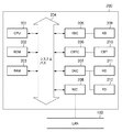
図1は、本発明の一実施形態によるネットワークデバイス管理システム及び管理対象のデバイスを含むネットワークを介したデバイス管理システムの概要を示す図である。
【0024】
図1において、ローカルエリアネットワーク(以下、「LAN」と称す。)100には、ネットワークボード101を備え、開放型アーキテクチャを持つプリンタ(デバイス)102と、本発明に係るネットワークデバイス管理システムのクライアント装置として機能するパーソナルコンピュータ(以下、「PC」と称す。)103と、プリンタ105に接続するPC104と、ネットワークディスク107に接続するファイルサーバ106と、プリンタ109a、109bに接続するプリンタサーバ108と、本発明に係るネットワークデバイス管理システムのサーバ装置として機能するPC121と、モデム/トランスポンダ130とが接続している。
【0025】
また、LAN120には、PC122と、モデム/トランスポンダ131に接続するバックボーン140とが接続している。そして、モデム/トランスボンダ130とモデム/トランスボンダ131とは、互いに広域ネットワーク(WAN)を介して接続されている。
【0026】
さらに、LAN110には、LAN120にも接続するモデム/トランスボンダ131と、PC110と、PC112と、ネットワークディスク114に接続するファイルサーバ113と、プリンタ116、117に接続するPC115が接続している。
【0027】
図2は、本発明に係るネットワークデバイス管理システムを実現するPC103又はPC121等のPCの構成を示す図である。図2に示すように、PC200は、CPU201と、ROM202と、RAM203と、キーボード(KB)209に接続するキーボードコントローラ(KBC)205と、CRT210に接続するCRTコントローラ(CRTC)206と、ハードディスク(HD)211及びフレキシブルディスクドライブ(FD)に接続するディスクコントローラ(DKC)207と、LAN100に接続するネットワークインタフェースカード(NIC)がシステムバス204を介して接続されている。
【0028】
尚、図2に示すPC200は、図1におけるPC103、PC121だけに限らず、PC104、108、122、111、112、115も同様の構成であってもよい。図2に示すPC200におけるHD211には、後述するすべての説明での動作主体となる本発明に係るネットワーク管理ソフトウェアに関するプログラムが格納されている。
【0029】
また、CPU201は、後述するすべての説明において特に断りのない限り、ハードウェア上の制御の主体である。一方、ソフトウェア上の制御の主体は、HD211に格納されたプログラムで実行されるネットワーク管理ソフトウェアである。尚、本実施形態においては、オペレーティングシステム(以下、「OS」と称す。)として、マイクロソフト社製のウィンドウズ2000を想定しているが、これに限られるものではなく、その他のOSであってもよい。
【0030】
尚、本実施形態におけるネットワーク管理プログラムは、フレキシブルディスクやCD−ROM等の記憶媒体に格納された形式で供給されてもよい。この場合、図2に示すFD212又は不図示のCD−ROMドライブ等によって記憶媒体に格納されたプログラムが読み取られ、HD211にインストールされるものであってもよい。
【0031】
尚、以下の説明においては、ネットワーク管理ソフトウェアのGUI(Graphical User Interface)部分のプロセス(クライアントアプリケーション)を「NetSpot GUI」と称し、デバイスと通信する部分のプロセス(サーバアプリケーション)を「VDC」と称す。
【0032】
図3は、LAN100に接続されたPC103、PC121及びプリンタ102間のプロセス通信を説明するための図である。本実施形態では、図3に示すように、PC103上でNetSpot GUIのプロセス、PC121上でVDCのプロセスがそれぞれ起動されて、プリンタ102が管理される。すなわち、NetSpot GUIは、プロセス間通信の機能を使用してVDCとデータ通信を行い、VDCは、SNMPプロトコルを使用して所定の管理対象デバイス(ここでは、プリンタ102)と通信を行う。尚、同一PC上において、NetSpot GUI及びVDCのプロセスを起動してプリンタ102を管理するようなシステムであってもよい。この場合も、プロセス間通信等の処理は同様である。
【0033】
ここで、ネットワークデバイス管理システムが、管理対象デバイスからデバイス構成情報を取得する場合の処理手順について説明する。
【0034】
まず、PC103におけるNetSpot GUIによってプロキシを用いたプロセス間通信が行われ、VDCに対して取得したいデバイス構成情報を送信する。次いで、VDCは、スタブでNetSpot GUIから受信した情報を受け取り、SNMPプロトコルを用いてデバイスからMIB情報を取得する。このようにして取得したデバイスMIB情報は、VDCのスタブからプロセス間通信を使用してプロキシに送信され、プロキシからNetSpot GUIにコールバック通知される。そして、NetSpot GUIは、プロキシからコールバック通知された情報に基づいてビットマップ表示等を行うことによってデバイス構成情報を表示する。
【0035】
次に、ネットワークデバイス管理システムが、管理対象デバイスに対してデバイス構成情報を設定する場合の処理手順について説明する。
【0036】
まず、NetSpot GUIは、プロキシを用いてプロセス間通信を行い、VDCに対して設定したいデバイス構成情報を送信する。次いで、VDCは、スタブでNetSpot GUIからの情報を受け取り、SNMPプロトコルを用いてデバイスに対してデバイスMIB情報を設定する。尚、デバイスでの設定が成功したか失敗したかを示す設定情報が、VDCのスタブからプロセス間通信を使用してプロキシに送信され、プロキシからNetSpot GUIにコールバック通知される。そして、NetSpot GUIは、プロキシからコールバック通知された情報に基づいてビットマップ表示等を行うことによってデバイス構成情報の設定結果を表示する。
【0037】
図4は、NetSpot GUIが所定の管理対象デバイスに関するジョブ情報(以下、「デバイスジョブ情報」と称す。)を表示する画面の一例を示す図である。NetSpot GUIは、デバイスからデバイスジョブ情報を取得するためにプロキシを用いてプロセス間通信を行い、VDCに対してデバイスジョブ情報の取得命令を送信する。VDCは、スタブでデバイスジョブ情報の取得命令を受け取り、例えば、SNMPプロトコルを用いたJob MIB、IPP(Internet Printing Protocol)等のデバイスジョブ情報取得用プロトコルを用いて、デバイスからジョブ情報を取得する。
【0038】
取得されたデバイスジョブ情報は、VDCのスタブからプロセス間通信を使用してプロキシに送信され、プロキシからNetSpot GUIにコールバック通知される。そして、NetSpot GUIは、プロキシからコールバック通知されたデバイスジョブ情報に基づいて、図4に示されるような画面を用いて当該デバイスジョブ情報のリスト表示を行う。
【0039】
また、NetSpot GUIは、プリンタ(デバイス)102におけるジョブの印刷終了状態を確実に検知するために、デバイスのジョブログ情報を取得する。NetSpot GUIは、プロキシを用いてプロセス間通信を行い、VDCにジョブログ情報取得要求を送信する。VDCは、スタブで受信したジョブログ情報の取得要求を受け取り、デバイスからジョブログ情報を取得する。VDCは、デバイスから取得したジョブログ情報をNetSpot GUIにコールバック通知し、NetSpot GUIは、取得したジョブログ情報から印刷が終了しているジョブを検出して、ジョブ状態を印刷終了状態に変更する表示を行う。
【0040】
図5は、NetSpot GUIにおいてジョブログ情報が表示されている画面を示す図である。デバイスからジョブログ情報を取得するために、NetSpot GUIは、プロキシを用いてプロセス間通信を行い、VDCにジョブログ情報の取得要求を送信する。VDCは、スタブで受信したジョブログ情報取得要求を受け取り、デバイスからジョブログ情報を取得する。そして、VDCは、デバイスから取得したジョブログ情報をNetSpot GUIにコールバック通知する。NetSpot GUIは、取得したジョブログ情報からジョブ受付番号、ジョブ名、ジョブオーナー名、印刷ページ数、印刷時刻及び印刷結果等を検出して、印刷が終了したジョブに関する情報の一覧を表示する。
【0041】
すなわち、本発明は、ネットワーク上に接続されたデバイスに関する情報をクライアント装置とサーバ装置とを用いて管理するネットワークデバイス管理システムである。そして、クライアント装置は、サーバ装置に対して、プロセス間通信によってデバイスに関するログ情報の取得を要求し、サーバ装置から取得したデバイスに関するログ情報を記憶し、デバイスに関するログ情報を表示し、新たに取得したログ情報に基づいて、表示されたデバイスに関するログ情報を変更させる。また、サーバ装置は、所定のプロトコルを用いて、デバイスに関するログ情報を取得し、クライアント装置に対して、要求されたログ情報をプロセス間通信によって送信する。
【0042】
次に、図面を参照して、上述した構成のVDC(サーバ側)のジョブログ情報取得動作、NetSpot GUI(クライアント側)のジョブログ情報取得要求動作、及びNetSpot GUIのジョブログ情報取得要求に対するVDCのレスポンス動作について詳細に説明する。
【0043】
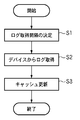
図6は、VDCによるジョブログ情報取得動作手順を説明するためのフローチャートである。以下、本実施形態では、VDCによるジョブログ情報取得動作について説明するが、VDCに関するログ情報取得動作はジョブログ情報に限るものではない。すなわち、ログ情報の種類として、ジョブログ情報以外にもデバイス内のエラー情報を示すエラーログ情報等が存在する。
【0044】
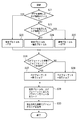
図6に示すように、まず、VDCではログ情報の取得間隔が決定される(ステップS1)。図7は、VDCにおけるログ情報取得間隔を決定する手順を詳細に説明するためのフローチャートである。ログ情報取得間隔の決定手順では、図7に示すように、まず、設定ファイルにログ情報を取得する間隔を示す取得間隔情報が存在するか否かがチェックされる(ステップS11)。本設定ファイルは、VDCが参照する静的な情報を格納するファイルである。その結果、取得情報間隔が存在する場合(YES)、ログ情報を取得する取得間隔を設定ファイルから読み出した値に設定する(ステップS14)。
【0045】
一方、ステップS11において取得情報間隔が存在しない場合(NO)、ログ情報取得対象のデバイスがハードディスクを搭載していないか否かがチェックされる(ステップS12)。その結果、デバイスがハードディスクを搭載している場合(NO)、デバイスはハードディスクサイズに応じて大量のレコード数を保持することができることになる。
【0046】
一方、ハードディスクを搭載していない場合(YES)、デバイスはRAM上でログを実現するために少量のレコード数しか保持することができない。そこで、ハードディスクを搭載していない場合、ログ情報を取得する取得間隔を「短」に設定する(ステップS15)。例えば、本実施形態では、ログ情報取得間隔を20秒に設定する。尚、この値は、ユーザのデバイス使用頻度においてチューニングすることが可能である。
【0047】
また、ステップS12においてデバイスがハードディスクを搭載している場合は、次に、デバイスが保持できるレコード数が一定レコード数よりも小さいか否かがチェックされる(ステップS13)。例えば、本実施形態では、256レコードよりも小さいかどうかをチェックする。ハードディスクを搭載しているデバイスにおいてハイエンドのデバイスは、搭載しているディスク容量が大きいので大量のログ情報を保持することができる。しかし、ローエンドのデバイスは、搭載しているディスク容量があまり大きくないので大量のレコードを保持することができない。
【0048】
その結果、デバイスが保持できるレコード数が一定レコード数(256レコード)よりも小さい場合(YES)、取得間隔を「中」に設定する(ステップS16)。例えば、本実施形態では、ログ情報取得間隔を1分に設定する。尚、この値は、ユーザのデバイス使用頻度においてチューニングすることが可能である。
【0049】
一方、デバイスが保持できるレコード数が一定レコード数(256レコード)よりも大きい場合(NO)、取得間隔を「長」に設定する(ステップS17)。例えば、本実施形態では、ログ情報取得間隔を3分に設定する。尚、この値は、ユーザのデバイス使用頻度においてチューニングすることが可能である。上述したように、本実施形態における取得間隔は、デバイスのハードディスク搭載の有無及びサイズで3つのレベルに設定しているが、3つのレベル以上の複数レベルの取得間隔を持つようにすることは可能である。
【0050】
すなわち、本発明に係るネットワークデバイス管理システムでは、サーバ装置は、デバイスに関するログ情報を所定の取得間隔で取得する。また、デバイスが保持可能なレコード数に応じて、前記取得間隔を設定する。さらに、デバイスのハードディスクの搭載の有無により取得間隔が設定される。
【0051】
VDCでは、ステップS1においてログ情報取得間隔が設定された後、デバイスからログ情報が取得される(ステップS2)。図8は、図6のステップS2におけるVDCがデイバスからログ情報を取得する動作手順を詳細に説明するためのフローチャートである。
【0052】
図8に示すように、VDCでは、まずFTPプロトコルを使用してログ情報を取得するデバイスか否かがチェックされる(ステップS21)。その結果、FTPプロトコルを使用する場合(YES)、使用プロトコルをFTPプロトコルに設定する(ステップS23)。一方、FTPプロトコルを使用しない場合(NO)、HTTPプロトコルを使用してログ情報を取得するデバイスか否かがチェックされる(ステップS22)。
【0053】
その結果、HTTPプロトコルを使用する場合(YES)、使用プロトコルをHTTPプロトコルに設定する(ステップS25)。一方で、HTTPプロトコルを使用しない場合(NO)、使用プロトコルを独自プロトコルに設定する(ステップS24)。
【0054】
ステップS23、S24、S25の処理が行われた後、取得するログ情報のフォーマットが終了ジョブフォーマットであるか否かがチェックされる(ステップS26)。その結果、終了ジョブフォーマットの場合(YES)、ログフォーマットを終了ジョブに設定する(ステップS27)。一方、終了ジョブフォーマットでない場合(NO)、ログフォーマットを実行ジョブに設定する(ステップS28)。
【0055】
終了ジョブフォーマットでは、ジョブID、ジョブ名、ジョブのオーナー名、印刷開始時刻、印刷終了時刻、ジョブ終了結果及び印刷ページ数等のフィールドを持つレコードが定義されている。実行ジョブフォーマットでは、ジョブID、ジョブ名、ジョブのオーナー名、印刷開始時刻、ジョブステータス及びページ数等のフィールドを持つレコードが定義されている。本実施形態では、終了ジョブフォーマット及び実行ジョブフォーマットの2種類が扱われるが、ログ情報のフォーマットはこれに限るものではない。
【0056】
さらに、使用するプロトコル、ログフォーマットの設定後、使用プロトコルに応じたプラグインモジュールがロードされる(ステップS29)。そして、ロードしたプラグインモジュールを使用して、図7のフローチャートで説明したログ情報取得間隔を用いてデバイスから定期的にログ情報が取得される(ステップS30)。すなわち、本発明に係るネットワークデバイス管理システムは、デバイスのログ機能に基づいて、使用可能なプロトコルが選択される。
【0057】
そして、ステップS2においてログ情報が取得された後、VDC内に保持していたログ情報のキャッシュが更新される(ステップS3)。図9は、VDCがデバイスから取得したログ情報をVDC内部のキャッシュに保存する動作手順を詳細に説明するためのフローチャートである。
【0058】
VDCでは、まず取得したログ情報からキャッシュに保存すべきログ情報が抽出される(ステップS31)。ジョブログ情報には、フィールドの一項目としてデバイスが選択しなかったIDが存在するので、取得したログの中からキャッシュに保存していないIDを持つレコードをキャッシュに保存すべきログ情報として抽出する。そして、それらの中からキャッシュを更新するログ情報が存在するか否かがチェックされる(ステップS32)。すなわち、ネットワーク管理ソフトウェアのサーバアプリケーションにおけるログキャッシュ機能を利用することにより、クライアントアプリケーションが必要とするログ情報のみ送受信してプロセス間通信のトラフィックを軽減することができる。
【0059】
すなわち、本発明に係るネットワークデバイス管理システムは、サーバ装置が、取得したログ情報を一時的に記憶し、新たに取得されたログ情報のうち、一時的に記憶されたログ情報を更新するログ情報のみをクライアント装置に対して送信する。
【0060】
その結果、キャッシュを更新するログ情報が存在する場合(YES)、キャッシュの内容を更新する(ステップS33)。一方、キャッシュを更新するログ情報が存在しない場合(NO)、処理を終了する。本実施形態では、ログ情報を保持(記憶)する手段としてVDC内部のメモリを使用したキャッシュを用いている。しかし、ログ情報を保持する手段は、VDC内部のキャッシュに限らず、データベースのようなVDC外に存在するデータ保持手段を使用することも可能である。
【0061】
すなわち、本発明に係るネットワークデバイス管理システムは、複数の管理対象デバイスが存在する場合、すべてのデバイスで同一レコード数を保持するようにしてもよい。また、デバイスが保持するログ情報のフォーマットの種類に基づいて、デバイスに関するログ情報を取得するようにしてもよい。
【0062】
また、VDCは、本キャッシュ機能を用いることにより、各デバイス内で保持できるレコード数が異なる場合であっても、VDC内部で一定量のレコード数を保持する仮想デバイスとして取り扱うことが可能である。また、いずれのデバイスにおいてもクライアントに同様の動作を提供することが可能になる。さらに、VDCのクライアントとして、サードパーティが開発するアプリケーションが存在するので、全てのデバイスにおいて共通のログ情報取得方法を提供することにより、クライアントアプリケーションの開発効率が向上する。すなわち、ネットワーク管理ソフトウェアのサーバアプリケーションが管理対象デバイスの差異を吸収した仮想デバイスとして振舞うことにより、異なるアクセス方法を提供しているデバイス群に対して共通のログ情報取得方法を提供し、クライアントアプリケーションがデバイス毎の違いを意識しない単純な動作を行うことができる。
【0063】
次に、クライアント側のログ情報取得動作について説明する。図10は、NetSpot GUI(クライアント側)のログ情報取得動作手順を説明するためのフローチャートである。図5に示すように、まずNetSpot GUIでは、VDCに対してログ情報の取得要求を行う間隔であるログ情報取得間隔に関する情報が設定ファイルに記載されているか否かがチェックされる(ステップS101)。
【0064】
その結果、設定ファイルに記載がある場合(YES)、NetSpot GUIがVDCへログ情報取得要求をする間隔を設定ファイルに記載された値にする(ステップS102)。一方、設定ファイルに記載がない場合(NO)、NetSpot GUIがVDCへログ情報取得要求をする間隔をVDCがデバイスにログ情報を取得する間隔より長い値を設定する(ステップS103)。本実施形態では、ログ情報取得要求をする間隔をVDCがデバイスにログ情報を取得する間隔の2倍の値に設定している。しかし、NetSpot GUIがVDCへログ情報取得要求に行く間隔は、VDCがデバイスにログ情報を取得する間隔より長い値であればどのような値であってもよい。
【0065】
次に、VDCでは最新の数レコードのみ取得するか否かがチェックされる(ステップS104)。図4に示したようなジョブの状態を変更するためにログ情報を使用する場合は、印刷が終了した最新の数レコードのみ必要であり、印刷が終了して数時間経過したレコードは必要ない。プロセス間通信の通信量を削減するために、必要な最新の数レコードのみVDCに取得要求することが可能である。すなわち、本発明に係るネットワークデバイス管理システムは、所定レコード数の最新のログ情報のみを取得する。
【0066】
一方、図5に示したようなデバイスの終了ジョブのログ情報一覧を表示する画面では、全てのレコードを取得する必要がある。この場合、VDC内でデバイスにかかわらず一定量のレコード数が保持されているため、どのデバイスでも同一のレコード数を表示することができる。従って、ステップS104において最新の数レコードのみ取得する場合(YES)、取得フラグを最新の数レコードに設定する(ステップS105)。また、最新の数レコードのみを取得しない場合(NO)、取得フラグを全レコードに設定する(ステップS106)。そして、ステップS105及びS106において取得フラグを設定した後、VDCにログ情報取得要求を発呼する(ステップS107)。
【0067】
図11は、クライアントからログ情報取得要求があったときのVDCの動作手順を説明するためのフローチャートである。図11に示すように、まずVDCは、クライアントからログ情報取得要求を受信する(ステップS111)。次いで、VDCは、キャッシュが存在するか否かをチェックする(ステップS112)。
【0068】
その結果、キャッシュが存在すると判定された場合(YES)、取得レコード数に応じてレコードセットを作成する(ステップS114)。一方、キャッシュが存在しないと判定された場合(NO)、図5に示したVDCのデバイスへのログ情報取得動作に従って、デバイスからログ情報を取得する(ステップS113)。そして、ステップS113又はS114における動作の後、VDCは、クライアントにレコードセットを返信する(ステップS115)。このとき、クライアントは、返信されたレコードセットに応じて、アプリケーションの表示を変更する。
【0069】
本発明は、上述したように、複数の機器(例えば、ホストコンピュータ、インタフェース機器、リーダ、プリンタ等)から構成されるシステムに適用しても、一つの機器からなる装置(例えば、複写機、ファクシミリ装置等)に適用してもよい。
【0070】
また、本発明の目的は、前述した実施形態の機能を実現するソフトウェアのプログラムコードを記録した記録媒体(または記憶媒体)を、システムあるいは装置に供給し、そのシステムあるいは装置のコンピュータ(またはCPUやMPU)が記録媒体に格納されたプログラムコードを読み出し実行することによっても、達成されることは言うまでもない。この場合、記録媒体から読み出されたプログラムコード自体が前述した実施形態の機能を実現することになり、そのプログラムコードを記録した記録媒体は本発明を構成することになる。また、コンピュータが読み出したプログラムコードを実行することにより、前述した実施形態の機能が実現されるだけでなく、そのプログラムコードの指示に基づき、コンピュータ上で稼働しているオペレーティングシステム(OS)などが実際の処理の一部または全部を行い、その処理によって前述した実施形態の機能が実現される場合も含まれることは言うまでもない。
【0071】
さらに、記録媒体から読み出されたプログラムコードが、コンピュータに挿入された機能拡張カードやコンピュータに接続された機能拡張ユニットに備わるメモリに書込まれた後、そのプログラムコードの指示に基づき、その機能拡張カードや機能拡張ユニットに備わるCPUなどが実際の処理の一部または全部を行い、その処理によって前述した実施形態の機能が実現される場合も含まれることは言うまでもない。
【0072】
本発明を上記記録媒体に適用する場合、その記録媒体には、先に説明したフローチャートに対応するプログラムコードが格納されることになる。
【0073】
【発明の効果】
以上説明したように、本発明によれば、クライアントアプリケーションの動作を簡単にするとともに、プロセス間通信のトラフィックを小さくすることができる。
【図面の簡単な説明】
【図1】本発明の一実施形態によるネットワークデバイス管理システム及び管理対象のデバイスを含むネットワークを介したデバイス管理システムの概要を示す図である。
【図2】本発明に係るネットワークデバイス管理システムを実現するPC103又はPC121等のPCの構成を示す図である。
【図3】LAN100に接続されたPC103、PC121及びプリンタ102間のプロセス通信を説明するための図である。
【図4】NetSpot GUIが所定の管理対象デバイスに関するジョブ情報を表示する画面の一例を示す図である。
【図5】NetSpot GUIにおいてジョブログ情報が表示されている画面を示す図である。
【図6】VDCによるジョブログ情報取得動作手順を説明するためのフローチャートである。
【図7】VDCにおけるログ情報取得間隔を決定する手順を詳細に説明するためのフローチャートである。
【図8】図6のステップS2におけるVDCがデイバスからログ情報を取得する動作手順を詳細に説明するためのフローチャートである。
【図9】VDCがデバイスから取得したログ情報をVDC内部のキャッシュに保存する動作手順を詳細に説明するためのフローチャートである。
【図10】NetSpot GUI(クライアント側)のログ情報取得動作手順を説明するためのフローチャートである。
【図11】クライアントからログ情報取得要求があったときのVDCの動作手順を説明するためのフローチャートである。
【符号の説明】
100 LAN
102 プリンタ
103、121、200 パーソナルコンピュータ
201 CPU
202 ROM
203 RAM
204 システムバス
205 キーボードコントローラ
206 CRTコントローラ
207 ディスクコントローラ
208 ネットワークインタフェースカード
209 キーボード
210 CRT
211 ハードディスク
212 フレキシブルディスクドライブ[0001]
BACKGROUND OF THE INVENTION
The present invention relates to a computer network, and more particularly to a network device management system including network management software for managing various devices connected to the network, and a control method thereof.
[0002]
[Prior art]
As a method for managing various devices connected to the network (hereinafter referred to as “network device”), a method using SNMP (Simple Network Management Protocol) / MIB (Management Information Base) is known (SNMP. / For details on MIB, see "Introduction to TCP / IP Network Management for Practical Management", MT Rose / Translated by Takeshi Nishida, Toppan Co., Ltd., published on August 20, 1992) .
[0003]
According to the SNMP network management technology, a network management system includes at least one network management station (NMS), several managed nodes each including an agent, and the network management station and the agent exchange management information. Network management protocol to be used. Then, the user uses the network management software on the network management station to communicate with the agent software on the managed node, thereby obtaining data related to the managed object via the network, and changing the data. Can do.
[0004]
As a method for uploading or downloading a large amount of data between terminals on a network, there is a method using an FTP (File Transfer Protocol) protocol. FTP is defined in RFC (Request for Comments) 959 as a standard for file transfer. That is, RFC959 defines an FTP communication model, data type, file structure, transfer mode, FTP command, and the like. FTP is composed of an FTP client and an FTP server, and transfers files by establishing two sessions between a client / server, a control session for transferring control commands and a data session for transferring data. .
[0005]
For example, FTP is also used when large-capacity data is transmitted and received between a network device management system that is an FTP client and a network device that is an FTP server. In this case, the network device management system can acquire or change resources in the network device by using the FTP protocol for the network device to be managed, updating or downloading large-capacity data. Note that the types of resources include font data, calibration data, log information, and the like.
[0006]
When software for network device management (network management software) as described above is used in a distributed environment, a client / server using a server application having a network device management function and a client application started on each terminal In general, the system configuration is based on the system.
[0007]
For example, RFC 1057 RPC (Remote Procedure Call) is defined as a standard for performing inter-process communication between different terminals using a client application and a server application. In this RPC, a group of functions for providing a network service is prepared on the server side, and functions provided by the server can be called by a client process of another terminal on the network in the same manner as a function in the local machine.
[0008]
The flow of interprocess communication in RPC is as follows. First, the client calls an RPC function prepared in the server as a service request to the server. At this point, a data packet storing function call information is sent from the client to the server, and execution of the client program is interrupted. When the server receives the data packet, it dispatches the called function, retrieves the argument of the function, executes the service based on the argument, and returns the result to the client. The client resumes program execution after receiving the result of the function.
[0009]
For data transmission / reception between the client / server, external data representation called XDR (external data representation), which is a standard data representation method that flows on the network, is used. Here, the conversion from the internal data representation to the XDR format is called “serialization”, and the conversion from the XDR format to the internal data representation is called “deserialization”. The transmission / reception data to be created increases or decreases depending on the data size of the function argument.
[0010]
[Problems to be solved by the invention]
However, in the conventional network device management system as described above, the client application using the network management software has different log information acquisition procedures such as the log information acquisition request interval and the acquisition protocol for each device to be managed. There is a problem that the operation of the client application becomes complicated.
[0011]
Further, in the conventional network device management system, since a large amount of log information is transmitted / received in data communication between the client application and the server application, there is a problem that traffic of inter-process communication increases.
[0012]
The present invention has been made in consideration of such circumstances, and provides a network device management system and a control method thereof that can simplify the operation of a client application and reduce the traffic of interprocess communication. For the purpose.
[0013]
[Means for Solving the Problems]
In order to solve the above problems , according to the present invention, there is provided a server apparatus capable of communicating with an image forming apparatus and transmitting information on the image forming apparatus to the client apparatus in response to a request from the client apparatus. A determination unit that determines an acquisition interval when acquiring log information related to image formation from the image forming device based on the number of records that can be stored by the image forming device, and the acquisition interval determined by the determination unit. An acquisition unit that acquires the log information from the image forming apparatus; and a transmission unit that transmits the acquired log information to the client device in response to a request from the client device. A first determination unit configured to determine whether or not the image forming apparatus is equipped with a hard disk; and the first determination unit includes a hard disk connected to the image forming apparatus. Second determination means for determining whether or not the number of records that can be stored by the image forming apparatus is smaller than a predetermined value when it is determined that the image forming apparatus is loaded, and the determination means includes: If the first determination means determines that the image forming apparatus is not equipped with a hard disk, the acquisition interval is determined as a first interval, and the first determination means determines that the image forming apparatus is equipped with a hard disk. And when the second determination means determines that the number of records is smaller than a predetermined value, the acquisition interval is determined as a second interval, and the first determination means If the image forming apparatus determines that the hard disk is mounted, and the second determination unit does not determine that the number of records is smaller than a predetermined value, the acquisition interval is set to a third interval. Decide on Wherein the first distance is shorter than the second distance, the second distance is a server apparatus characterized by shorter than the third interval is provided.
[0015]
Furthermore, the server device according to the present invention further includes a temporary storage unit that temporarily stores the acquired log information, and the transmitting unit temporarily stores the log information among the newly acquired log information. Only log information for updating the server is transmitted to the client device.
[0021]
Furthermore, in the server device according to the present invention, the acquisition unit acquires only the latest log information of a predetermined number of records. As a result, the amount of communication by the transmission means can be reduced.
[0022]
DETAILED DESCRIPTION OF THE INVENTION
Hereinafter, a network device management system according to an embodiment of the present invention and its peripheral devices connected via a network will be described with reference to the drawings.
[0023]
FIG. 1 is a diagram illustrating an overview of a network device management system and a device management system via a network including devices to be managed according to an embodiment of the present invention.
[0024]
In FIG. 1, a local area network (hereinafter referred to as “LAN”) 100 includes a
[0025]
Further, a
[0026]
Further, a modem / transbonder 131 that is also connected to the
[0027]
FIG. 2 is a diagram showing a configuration of a PC such as the
[0028]
2 is not limited to the
[0029]
In addition, the
[0030]
Note that the network management program in the present embodiment may be supplied in a format stored in a storage medium such as a flexible disk or a CD-ROM. In this case, the program stored in the storage medium may be read by the
[0031]
In the following description, the process (client application) of the GUI (Graphical User Interface) part of the network management software is referred to as “NetSpot GUI”, and the process (server application) of the part communicating with the device is referred to as “VDC”. .
[0032]
FIG. 3 is a diagram for explaining process communication between the
[0033]
Here, a processing procedure when the network device management system acquires device configuration information from the management target device will be described.
[0034]
First, inter-process communication using a proxy is performed by the NetSpot GUI in the
[0035]
Next, a processing procedure when the network device management system sets device configuration information for a management target device will be described.
[0036]
First, the NetSpot GUI performs inter-process communication using a proxy and transmits device configuration information to be set to the VDC. The VDC then receives information from the NetSpot GUI with a stub and sets device MIB information for the device using the SNMP protocol. Note that setting information indicating whether the setting on the device has succeeded or failed is transmitted from the VDC stub to the proxy using inter-process communication, and the proxy notifies the NetSpot GUI of a callback. Then, the NetSpot GUI displays the setting result of the device configuration information by performing bitmap display or the like based on the information notified of the callback from the proxy.
[0037]
FIG. 4 is a diagram illustrating an example of a screen on which the NetSpot GUI displays job information related to a predetermined management target device (hereinafter referred to as “device job information”). The NetSpot GUI performs inter-process communication using a proxy to acquire device job information from the device, and transmits a device job information acquisition command to the VDC. The VDC receives a device job information acquisition command via a stub, and acquires job information from the device using a device job information acquisition protocol such as Job MIB or IPP (Internet Printing Protocol) using the SNMP protocol.
[0038]
The acquired device job information is transmitted from the VDC stub to the proxy using inter-process communication, and the proxy notifies the NetSpot GUI of a callback. Then, the NetSpot GUI displays a list of the device job information using a screen as shown in FIG. 4 based on the device job information notified of the callback from the proxy.
[0039]
Further, the NetSpot GUI acquires device job log information in order to reliably detect the print end state of the job in the printer (device) 102. The NetSpot GUI performs inter-process communication using a proxy and transmits a job log information acquisition request to the VDC. The VDC receives the job log information acquisition request received by the stub and acquires the job log information from the device. The VDC notifies the NetSpot GUI of the job log information acquired from the device, and the NetSpot GUI detects a job that has been printed from the acquired job log information, and changes the job status to the print completed status. Display.
[0040]
FIG. 5 is a diagram showing a screen on which job log information is displayed in the NetSpot GUI. In order to acquire job log information from the device, the NetSpot GUI performs inter-process communication using a proxy, and transmits a job log information acquisition request to the VDC. The VDC receives the job log information acquisition request received by the stub and acquires the job log information from the device. Then, the VDC notifies the NetSpot GUI of the job log information acquired from the device with a callback notification. The NetSpot GUI detects a job reception number, job name, job owner name, number of print pages, print time, print result, and the like from the acquired job log information, and displays a list of information about jobs for which printing has ended.
[0041]
That is, the present invention is a network device management system that manages information about devices connected on a network using a client device and a server device. Then, the client device requests the server device to acquire log information about the device through inter-process communication, stores the log information about the device acquired from the server device, displays the log information about the device, and newly acquires it. Based on the log information, the log information on the displayed device is changed. In addition, the server apparatus acquires log information about the device using a predetermined protocol, and transmits the requested log information to the client apparatus by inter-process communication.
[0042]
Next, referring to the drawings, the job log information acquisition operation of the VDC (server side) configured as described above, the job log information acquisition request operation of the NetSpot GUI (client side), and the job log information acquisition request of the NetSpot GUI The response operation will be described in detail.
[0043]
FIG. 6 is a flowchart for explaining a job log information acquisition operation procedure by the VDC. Hereinafter, the job log information acquisition operation by the VDC will be described in the present embodiment, but the log information acquisition operation regarding the VDC is not limited to the job log information. That is, as log information types, there are error log information indicating error information in the device in addition to job log information.
[0044]
As shown in FIG. 6, first, the log information acquisition interval is determined in the VDC (step S1). FIG. 7 is a flowchart for explaining in detail the procedure for determining the log information acquisition interval in the VDC. In the procedure for determining the log information acquisition interval, as shown in FIG. 7, first, it is checked whether or not acquisition interval information indicating an interval for acquiring log information exists in the setting file (step S11). This setting file is a file for storing static information referred to by the VDC. As a result, if there is an acquisition information interval (YES), the acquisition interval for acquiring log information is set to the value read from the setting file (step S14).
[0045]
On the other hand, if the acquisition information interval does not exist in step S11 (NO), it is checked whether the log information acquisition target device is equipped with a hard disk (step S12). As a result, when the device is equipped with a hard disk (NO), the device can hold a large number of records according to the hard disk size.
[0046]
On the other hand, when the hard disk is not installed (YES), the device can hold only a small number of records in order to implement the log on the RAM. Therefore, when the hard disk is not installed, the acquisition interval for acquiring the log information is set to “short” (step S15). For example, in this embodiment, the log information acquisition interval is set to 20 seconds. This value can be tuned according to the user's device usage frequency.
[0047]
If the device is equipped with a hard disk in step S12, it is next checked whether the number of records that the device can hold is smaller than a certain number of records (step S13). For example, in this embodiment, it is checked whether it is smaller than 256 records. A high-end device having a hard disk can hold a large amount of log information because the mounted disk capacity is large. However, low-end devices cannot hold a large number of records because the installed disk capacity is not so large.
[0048]
As a result, when the number of records that can be held by the device is smaller than the certain number of records (256 records) (YES), the acquisition interval is set to “medium” (step S16). For example, in this embodiment, the log information acquisition interval is set to 1 minute. This value can be tuned according to the user's device usage frequency.
[0049]
On the other hand, when the number of records that the device can hold is larger than the certain number of records (256 records) (NO), the acquisition interval is set to “long” (step S17). For example, in this embodiment, the log information acquisition interval is set to 3 minutes. This value can be tuned according to the user's device usage frequency. As described above, the acquisition interval in the present embodiment is set to three levels depending on whether or not the device is equipped with a hard disk and the size, but it is possible to have a plurality of acquisition intervals of three or more levels. It is.
[0050]
That is, in the network device management system according to the present invention, the server device acquires log information about the device at a predetermined acquisition interval. Further, the acquisition interval is set according to the number of records that can be held by the device. Furthermore, the acquisition interval is set depending on whether or not the device has a hard disk installed.
[0051]
In the VDC, after the log information acquisition interval is set in step S1, log information is acquired from the device (step S2). FIG. 8 is a flowchart for explaining in detail an operation procedure in which the VDC acquires log information from the device in step S2 of FIG.
[0052]
As shown in FIG. 8, the VDC first checks whether the device acquires log information using the FTP protocol (step S21). As a result, when the FTP protocol is used (YES), the used protocol is set to the FTP protocol (step S23). On the other hand, when the FTP protocol is not used (NO), it is checked whether the device acquires log information using the HTTP protocol (step S22).
[0053]
As a result, when the HTTP protocol is used (YES), the used protocol is set to the HTTP protocol (step S25). On the other hand, when the HTTP protocol is not used (NO), the used protocol is set to a unique protocol (step S24).
[0054]
After the processes of steps S23, S24, and S25 are performed, it is checked whether or not the format of the log information to be acquired is the end job format (step S26). As a result, in the case of the end job format (YES), the log format is set to the end job (step S27). On the other hand, if it is not the end job format (NO), the log format is set to the execution job (step S28).
[0055]
In the end job format, a record having fields such as job ID, job name, job owner name, print start time, print end time, job end result, and number of print pages is defined. In the execution job format, a record having fields such as job ID, job name, job owner name, print start time, job status, and number of pages is defined. In the present embodiment, two types of end job format and execution job format are handled, but the format of log information is not limited to this.
[0056]
Further, after setting the protocol to be used and the log format, a plug-in module corresponding to the protocol to be used is loaded (step S29). Then, using the loaded plug-in module, log information is periodically acquired from the device using the log information acquisition interval described in the flowchart of FIG. 7 (step S30). That is, in the network device management system according to the present invention, a usable protocol is selected based on the log function of the device.
[0057]
Then, after the log information is acquired in step S2, the log information cache held in the VDC is updated (step S3). FIG. 9 is a flowchart for explaining in detail an operation procedure in which the log information acquired from the device by the VDC is stored in the cache inside the VDC.
[0058]
In the VDC, first, log information to be stored in the cache is extracted from the acquired log information (step S31). In the job log information, there is an ID that is not selected by the device as one item of the field. Therefore, a record having an ID not stored in the cache is extracted as log information to be stored in the cache from the acquired logs. . Then, it is checked whether or not there is log information for updating the cache (step S32). In other words, by using the log cache function in the server application of the network management software, it is possible to reduce only the log information required by the client application and reduce inter-process communication traffic.
[0059]
That is, in the network device management system according to the present invention, the server device temporarily stores the acquired log information, and the log information for updating the temporarily stored log information among the newly acquired log information. Only to the client device.
[0060]
As a result, if there is log information for updating the cache (YES), the contents of the cache are updated (step S33). On the other hand, if there is no log information for updating the cache (NO), the process is terminated. In this embodiment, a cache using a memory inside the VDC is used as means for holding (storing) log information. However, the means for holding the log information is not limited to the cache inside the VDC, but a data holding means that exists outside the VDC, such as a database, can also be used.
[0061]
That is, the network device management system according to the present invention may hold the same number of records in all devices when there are a plurality of devices to be managed. Further, log information related to the device may be acquired based on the type of format of log information held by the device.
[0062]
Further, by using this cache function, the VDC can be handled as a virtual device that holds a certain number of records inside the VDC even when the number of records that can be held in each device is different. In any device, the same operation can be provided to the client. Furthermore, since there are applications developed by third parties as VDC clients, providing a common log information acquisition method for all devices improves the development efficiency of client applications. In other words, the server application of the network management software behaves as a virtual device that absorbs the differences in the managed devices, thereby providing a common log information acquisition method for a group of devices that provide different access methods. It is possible to perform simple operations that are not conscious of differences between devices.
[0063]
Next, the log information acquisition operation on the client side will be described. FIG. 10 is a flowchart for explaining the log information acquisition operation procedure of the NetSpot GUI (client side). As shown in FIG. 5, first, in the NetSpot GUI, it is checked whether or not information related to a log information acquisition interval, which is an interval for making a log information acquisition request to the VDC, is described in the setting file (step S101). .
[0064]
As a result, when there is a description in the setting file (YES), the interval at which the NetSpot GUI makes a log information acquisition request to the VDC is set to a value described in the setting file (step S102). On the other hand, if there is no description in the setting file (NO), the interval at which the NetSpot GUI makes a log information acquisition request to the VDC is set to a value longer than the interval at which the VDC acquires log information from the device (step S103). In this embodiment, the log information acquisition request interval is set to a value twice the interval at which the VDC acquires log information from the device. However, the interval at which the NetSpot GUI makes a log information acquisition request to the VDC may be any value as long as it is longer than the interval at which the VDC acquires log information from the device.
[0065]
Next, in the VDC, it is checked whether or not only the latest few records are acquired (step S104). When log information is used to change the job status as shown in FIG. 4, only the latest few records that have been printed are required, and records that have been printed for several hours are not necessary. In order to reduce the amount of inter-process communication, it is possible to make an acquisition request to the VDC for only the latest necessary several records. That is, the network device management system according to the present invention acquires only the latest log information of a predetermined number of records.
[0066]
On the other hand, on the screen for displaying the log information list of the end job of the device as shown in FIG. 5, it is necessary to acquire all records. In this case, since a certain number of records are held in the VDC regardless of the device, the same number of records can be displayed on any device. Therefore, when only the latest few records are acquired in step S104 (YES), the acquisition flag is set to the latest several records (step S105). If only the latest few records are not acquired (NO), the acquisition flag is set for all records (step S106). Then, after setting an acquisition flag in steps S105 and S106, a log information acquisition request is issued to the VDC (step S107).
[0067]
FIG. 11 is a flowchart for explaining an operation procedure of the VDC when a log information acquisition request is issued from the client. As shown in FIG. 11, first, the VDC receives a log information acquisition request from the client (step S111). Next, the VDC checks whether or not a cache exists (step S112).
[0068]
As a result, when it is determined that a cache exists (YES), a record set is created according to the number of acquired records (step S114). On the other hand, if it is determined that there is no cache (NO), log information is acquired from the device according to the log information acquisition operation for the VDC device shown in FIG. 5 (step S113). Then, after the operation in step S113 or S114, the VDC returns a record set to the client (step S115). At this time, the client changes the display of the application according to the returned record set.
[0069]
As described above, the present invention can be applied to a system constituted by a plurality of devices (for example, a host computer, an interface device, a reader, a printer, etc.), but an apparatus (for example, a copying machine, a facsimile machine) composed of a single device. It may be applied to a device etc.
[0070]
Also, an object of the present invention is to supply a recording medium (or storage medium) in which a program code of software that realizes the functions of the above-described embodiments is recorded to a system or apparatus, and a computer (or CPU or CPU) of the system or apparatus. Needless to say, this can also be achieved when the MPU) reads and executes the program code stored in the recording medium. In this case, the program code itself read from the recording medium realizes the functions of the above-described embodiment, and the recording medium on which the program code is recorded constitutes the present invention. Further, by executing the program code read by the computer, not only the functions of the above-described embodiments are realized, but also an operating system (OS) running on the computer based on the instruction of the program code. It goes without saying that a case where the function of the above-described embodiment is realized by performing part or all of the actual processing and the processing is included.
[0071]
Furthermore, after the program code read from the recording medium is written into a memory provided in a function expansion card inserted into the computer or a function expansion unit connected to the computer, the function is based on the instruction of the program code. It goes without saying that the CPU or the like provided in the expansion card or the function expansion unit performs part or all of the actual processing and the functions of the above-described embodiments are realized by the processing.
[0072]
When the present invention is applied to the recording medium, program code corresponding to the flowchart described above is stored in the recording medium.
[0073]
【The invention's effect】
As described above, according to the present invention, it is possible to simplify the operation of the client application and reduce the traffic of interprocess communication.
[Brief description of the drawings]
FIG. 1 is a diagram showing an overview of a network device management system and a device management system via a network including devices to be managed according to an embodiment of the present invention.
FIG. 2 is a diagram showing a configuration of a PC such as a
3 is a diagram for explaining process communication between a
FIG. 4 is a diagram illustrating an example of a screen on which the NetSpot GUI displays job information related to a predetermined management target device.
FIG. 5 is a diagram showing a screen on which job log information is displayed in the NetSpot GUI.
FIG. 6 is a flowchart for explaining a job log information acquisition operation procedure by VDC;
FIG. 7 is a flowchart for explaining in detail a procedure for determining a log information acquisition interval in the VDC;
FIG. 8 is a flowchart for explaining in detail an operation procedure in which the VDC in step S2 of FIG. 6 acquires log information from the device.
FIG. 9 is a flowchart for explaining in detail an operation procedure for storing log information acquired from a device by a VDC in a cache inside the VDC;
FIG. 10 is a flowchart for explaining a log information acquisition operation procedure of the NetSpot GUI (client side).
FIG. 11 is a flowchart for explaining an operation procedure of a VDC when a log information acquisition request is made from a client;
[Explanation of symbols]
100 LAN
102
202 ROM
203 RAM
204
211
Claims (8)
前記画像形成装置から画像形成に関するログ情報を取得する際の取得間隔を、前記画像形成装置が記憶可能なレコード数に基づいて、決定する決定手段と、
前記決定手段が決定した前記取得間隔で、前記画像形成装置から前記ログ情報を取得する取得手段と、
前記クライアント装置の要求に応じて、取得された前記ログ情報を前記クライアント装置へ送信する送信手段と、
を備え、
前記決定手段は、
前記画像形成装置がハードディスクを搭載しているか否かを判定する第1判定手段と、
前記第1判定手段が前記画像形成装置がハードディスクを搭載していると判定した場合、該画像形成装置が記憶可能なレコード数が、予め定められた値よりも小さいか否かを判定する第2判定手段と、
を含み、
前記決定手段は、
前記第1判定手段が、前記画像形成装置がハードディスクを搭載していないと判定した場合は、前記取得間隔を第1の間隔に決定し、
前記第1判定手段が、前記画像形成装置がハードディスクを搭載していると判定し、さらに前記第2判定手段が、前記レコード数が予め定められた値よりも小さいと判定した場合は、前記取得間隔を第2の間隔に決定し、
前記第1判定手段が、前記画像形成装置がハードディスクを搭載していると判定し、さらに前記第2判定手段が、前記レコード数が予め定められた値よりも小さいと判定しない場合は、前記取得間隔を第3の間隔に決定し、
前記第1の間隔は前記第2の間隔よりも短く、前記第2の間隔は前記第3の間隔よりも短い
ことを特徴とするサーバ装置。A server device capable of communicating with an image forming apparatus and transmitting information of the image forming apparatus to the client device in response to a request from the client device;
Determining means for determining an acquisition interval when acquiring log information related to image formation from the image forming apparatus based on the number of records that the image forming apparatus can store;
Acquisition means for acquiring the log information from the image forming apparatus at the acquisition interval determined by the determination means;
Transmitting means for transmitting the acquired log information to the client device in response to a request from the client device;
With
The determining means includes
First determination means for determining whether or not the image forming apparatus is equipped with a hard disk;
A second determining unit configured to determine whether the number of records that can be stored in the image forming apparatus is smaller than a predetermined value when the first determining unit determines that the image forming apparatus includes a hard disk; A determination means;
Including
The determining means includes
If the first determination unit determines that the image forming apparatus is not equipped with a hard disk, the acquisition interval is determined as a first interval;
If the first determination unit determines that the image forming apparatus is equipped with a hard disk, and the second determination unit determines that the number of records is smaller than a predetermined value, the acquisition is performed. Determine the interval as the second interval;
If the first determination unit determines that the image forming apparatus is equipped with a hard disk, and the second determination unit does not determine that the number of records is smaller than a predetermined value, the acquisition is performed. Determine the interval as the third interval,
The server device, wherein the first interval is shorter than the second interval, and the second interval is shorter than the third interval.
前記送信手段が、新たに取得されたログ情報のうち、一時的に記憶されたログ情報を更新するログ情報のみを前記クライアント装置に対して送信する
ことを特徴とする請求項1に記載のサーバ装置。A temporary storage means for temporarily storing the acquired log information;
2. The server according to claim 1 , wherein the transmission unit transmits only the log information for updating the temporarily stored log information among the newly acquired log information to the client device. apparatus.
前記画像形成装置から画像形成に関するログ情報を取得する際の取得間隔を、前記画像形成装置が記憶可能なレコード数に基づいて、決定手段が決定する決定工程と、
前記決定手段が決定した前記取得間隔で、取得手段が前記画像形成装置から前記ログ情報を取得する取得工程と、
前記クライアント装置の要求に応じて、送信手段が、取得された前記ログ情報を前記クライアント装置へ送信する送信工程と、
を備え、
前記決定工程は、
前記画像形成装置がハードディスクを搭載しているか否かを判定し、 前記画像形成装置がハードディスクを搭載していないと判定した場合は、前記取得間隔を第1の間隔に決定し、
前記画像形成装置がハードディスクを搭載していると判定し、さらに前記レコード数が予め定められた値よりも小さいと判定し場合は、前記取得間隔を前記第1の間隔よりも長い第2の間隔に決定し、
前記画像形成装置がハードディスクを搭載していると判定し、さらに前記第2判定工程において前記レコード数が予め定められた値よりも小さいと判定しなかった場合は、前記取得間隔を前記第2の間隔よりも長い第3の間隔に決定
することを特徴とするサーバ装置の制御方法。A control method for a server device, which is communicable with an image forming device and transmits information of the image forming device to the client device in response to a request from the client device,
A determination step in which a determination unit determines an acquisition interval when acquiring log information related to image formation from the image forming apparatus based on the number of records that can be stored in the image forming apparatus;
An acquisition step in which the acquisition unit acquires the log information from the image forming apparatus at the acquisition interval determined by the determination unit;
In response to a request from the client device, a transmission unit transmits the acquired log information to the client device;
With
The determination step includes
It is determined whether the image forming apparatus is equipped with a hard disk. If it is determined that the image forming apparatus is not equipped with a hard disk, the acquisition interval is determined as a first interval,
If it is determined that the image forming apparatus is equipped with a hard disk, and if it is determined that the number of records is smaller than a predetermined value, the acquisition interval is a second interval longer than the first interval. Decided on
If it is determined that the image forming apparatus is equipped with a hard disk, and the second determination step does not determine that the number of records is smaller than a predetermined value, the acquisition interval is set to the second interval. A control method for a server apparatus, wherein the third interval is determined to be longer than the interval.
前記送信工程においては、新たに取得されたログ情報のうち、一時的に記憶されたログ情報を更新するログ情報のみが前記クライアント装置に対して送信される
ことを特徴とする請求項4に記載のサーバ装置の制御方法。The server device further comprises temporary storage means for temporarily storing the acquired log information;
Wherein in the transmission step, among the newly acquired log information, according to claim 4, only the log information to update the temporarily stored log information, characterized in that it is transmitted to the client device Server device control method.
Priority Applications (9)
| Application Number | Priority Date | Filing Date | Title |
|---|---|---|---|
| JP2002129329A JP3977135B2 (en) | 2002-04-30 | 2002-04-30 | Network device management system and control method thereof |
| US10/421,796 US7546365B2 (en) | 2002-04-30 | 2003-04-24 | Network device management system and method of controlling same |
| DE60306449T DE60306449D1 (en) | 2002-04-30 | 2003-04-25 | Method and system for monitoring a network device |
| EP07075580A EP1843522A3 (en) | 2002-04-30 | 2003-04-25 | Method and system for monitoring of a network device |
| EP06075784A EP1679825B1 (en) | 2002-04-30 | 2003-04-25 | Method and system for monitoring of a network device |
| DE60316048T DE60316048T2 (en) | 2002-04-30 | 2003-04-25 | Method and system for monitoring a network device |
| EP03252621A EP1361699B1 (en) | 2002-04-30 | 2003-04-25 | Method and system for monitoring of a network device |
| CN2009101656619A CN101635649B (en) | 2002-04-30 | 2003-04-29 | Network device management system and control method of the same |
| CNB031224997A CN100544272C (en) | 2002-04-30 | 2003-04-29 | Network apparatus management system and control method thereof |
Applications Claiming Priority (1)
| Application Number | Priority Date | Filing Date | Title |
|---|---|---|---|
| JP2002129329A JP3977135B2 (en) | 2002-04-30 | 2002-04-30 | Network device management system and control method thereof |
Related Child Applications (1)
| Application Number | Title | Priority Date | Filing Date |
|---|---|---|---|
| JP2007129917A Division JP4671438B2 (en) | 2007-05-15 | 2007-05-15 | Server apparatus and control method thereof |
Publications (3)
| Publication Number | Publication Date |
|---|---|
| JP2003323358A JP2003323358A (en) | 2003-11-14 |
| JP2003323358A5 JP2003323358A5 (en) | 2005-04-07 |
| JP3977135B2 true JP3977135B2 (en) | 2007-09-19 |
Family
ID=29542795
Family Applications (1)
| Application Number | Title | Priority Date | Filing Date |
|---|---|---|---|
| JP2002129329A Expired - Fee Related JP3977135B2 (en) | 2002-04-30 | 2002-04-30 | Network device management system and control method thereof |
Country Status (2)
| Country | Link |
|---|---|
| JP (1) | JP3977135B2 (en) |
| CN (1) | CN101635649B (en) |
Families Citing this family (5)
| Publication number | Priority date | Publication date | Assignee | Title |
|---|---|---|---|---|
| JP4625383B2 (en) * | 2005-08-25 | 2011-02-02 | 株式会社リコー | Job information display control device, job information display control system, job information display control method, job information display control program, and recording medium |
| JP5173495B2 (en) * | 2008-03-03 | 2013-04-03 | キヤノン株式会社 | Information processing apparatus, job processing method, and program |
| JP6141916B2 (en) * | 2015-07-23 | 2017-06-07 | スミス アンド ネフュー インコーポレイテッド | Method and system for reliable interoperability between medical devices |
| CN110209564A (en) * | 2019-06-03 | 2019-09-06 | 宜春宜联科技有限公司 | Acquisition methods, printer, server and the printer system of printer log |
| CN114281280B (en) * | 2021-12-31 | 2023-08-25 | 中企云链(北京)金融信息服务有限公司 | Log processing method and device, storage medium and electronic device |
Family Cites Families (3)
| Publication number | Priority date | Publication date | Assignee | Title |
|---|---|---|---|---|
| US4972367A (en) * | 1987-10-23 | 1990-11-20 | Allen-Bradley Company, Inc. | System for generating unsolicited messages on high-tier communication link in response to changed states at station-level computers |
| US5872966A (en) * | 1996-05-10 | 1999-02-16 | Apple Computer, Inc. | System and method for logging and enabling further manipulation of system state information |
| US5796633A (en) * | 1996-07-12 | 1998-08-18 | Electronic Data Systems Corporation | Method and system for performance monitoring in computer networks |
-
2002
- 2002-04-30 JP JP2002129329A patent/JP3977135B2/en not_active Expired - Fee Related
-
2003
- 2003-04-29 CN CN2009101656619A patent/CN101635649B/en not_active Expired - Fee Related
Also Published As
| Publication number | Publication date |
|---|---|
| CN101635649A (en) | 2010-01-27 |
| CN101635649B (en) | 2011-09-21 |
| JP2003323358A (en) | 2003-11-14 |
Similar Documents
| Publication | Publication Date | Title |
|---|---|---|
| US7546365B2 (en) | Network device management system and method of controlling same | |
| JP3684108B2 (en) | Network device management apparatus and method | |
| US8862997B2 (en) | Network management system and network management method | |
| US6539422B1 (en) | Automatic data collection device having a network communications capability | |
| EP2133790A1 (en) | MFP software update using web service | |
| US8676967B2 (en) | Event proxy notification apparatus and method of controlling the same and program | |
| US7468804B2 (en) | Techniques for printer-side network cluster printing | |
| JP4424910B2 (en) | System that allows arbitrary components to transfer data to each other | |
| JP2000330742A (en) | Network printer system | |
| JP3977135B2 (en) | Network device management system and control method thereof | |
| JP4671438B2 (en) | Server apparatus and control method thereof | |
| US20100332681A1 (en) | Communication apparatus capable of selecting a proper source address from a plurality of source addresses assigned thereto, method of controlling the same, and storage medium | |
| US20030055961A1 (en) | Network device management apparatus, management system, and management method, and network device | |
| JP2006011703A (en) | Information collection device, information collection method, information collection program and device management system | |
| JP3950736B2 (en) | Network device management system and control method thereof | |
| US7680896B2 (en) | Obtaining or sending information to a device on a network by a client apparatus | |
| US20010023444A1 (en) | Information processing apparatus, information processing method and information processing program for transmitting data to external apparatus for communication of information on device | |
| JP2006190029A (en) | Device and method for managing network device | |
| JP3826906B2 (en) | Communication management device | |
| EP1615379A1 (en) | Method for configuring a monitoring system to monitor selected network elements | |
| JP2000353142A (en) | Device and method for managing network | |
| JP2003204332A (en) | Network device management system and method of controlling the same |
Legal Events
| Date | Code | Title | Description |
|---|---|---|---|
| A521 | Written amendment |
Free format text: JAPANESE INTERMEDIATE CODE: A523 Effective date: 20040526 |
|
| A621 | Written request for application examination |
Free format text: JAPANESE INTERMEDIATE CODE: A621 Effective date: 20040526 |
|
| A131 | Notification of reasons for refusal |
Free format text: JAPANESE INTERMEDIATE CODE: A131 Effective date: 20061215 |
|
| A521 | Written amendment |
Free format text: JAPANESE INTERMEDIATE CODE: A523 Effective date: 20070213 |
|
| A131 | Notification of reasons for refusal |
Free format text: JAPANESE INTERMEDIATE CODE: A131 Effective date: 20070316 |
|
| A521 | Written amendment |
Free format text: JAPANESE INTERMEDIATE CODE: A523 Effective date: 20070515 |
|
| TRDD | Decision of grant or rejection written | ||
| A01 | Written decision to grant a patent or to grant a registration (utility model) |
Free format text: JAPANESE INTERMEDIATE CODE: A01 Effective date: 20070604 |
|
| A61 | First payment of annual fees (during grant procedure) |
Free format text: JAPANESE INTERMEDIATE CODE: A61 Effective date: 20070620 |
|
| FPAY | Renewal fee payment (event date is renewal date of database) |
Free format text: PAYMENT UNTIL: 20100629 Year of fee payment: 3 |
|
| R150 | Certificate of patent or registration of utility model |
Free format text: JAPANESE INTERMEDIATE CODE: R150 |
|
| FPAY | Renewal fee payment (event date is renewal date of database) |
Free format text: PAYMENT UNTIL: 20110629 Year of fee payment: 4 |
|
| FPAY | Renewal fee payment (event date is renewal date of database) |
Free format text: PAYMENT UNTIL: 20120629 Year of fee payment: 5 |
|
| FPAY | Renewal fee payment (event date is renewal date of database) |
Free format text: PAYMENT UNTIL: 20120629 Year of fee payment: 5 |
|
| FPAY | Renewal fee payment (event date is renewal date of database) |
Free format text: PAYMENT UNTIL: 20130629 Year of fee payment: 6 |
|
| LAPS | Cancellation because of no payment of annual fees |