JP3932806B2 - Driving control device for automobile - Google Patents
Driving control device for automobile Download PDFInfo
- Publication number
- JP3932806B2 JP3932806B2 JP2000523076A JP2000523076A JP3932806B2 JP 3932806 B2 JP3932806 B2 JP 3932806B2 JP 2000523076 A JP2000523076 A JP 2000523076A JP 2000523076 A JP2000523076 A JP 2000523076A JP 3932806 B2 JP3932806 B2 JP 3932806B2
- Authority
- JP
- Japan
- Prior art keywords
- vehicle
- speed
- preceding vehicle
- target
- yaw rate
- Prior art date
- Legal status (The legal status is an assumption and is not a legal conclusion. Google has not performed a legal analysis and makes no representation as to the accuracy of the status listed.)
- Expired - Fee Related
Links
Images


Classifications
-
- B—PERFORMING OPERATIONS; TRANSPORTING
- B60—VEHICLES IN GENERAL
- B60W—CONJOINT CONTROL OF VEHICLE SUB-UNITS OF DIFFERENT TYPE OR DIFFERENT FUNCTION; CONTROL SYSTEMS SPECIALLY ADAPTED FOR HYBRID VEHICLES; ROAD VEHICLE DRIVE CONTROL SYSTEMS FOR PURPOSES NOT RELATED TO THE CONTROL OF A PARTICULAR SUB-UNIT
- B60W10/00—Conjoint control of vehicle sub-units of different type or different function
- B60W10/10—Conjoint control of vehicle sub-units of different type or different function including control of change-speed gearings
-
- B—PERFORMING OPERATIONS; TRANSPORTING
- B60—VEHICLES IN GENERAL
- B60K—ARRANGEMENT OR MOUNTING OF PROPULSION UNITS OR OF TRANSMISSIONS IN VEHICLES; ARRANGEMENT OR MOUNTING OF PLURAL DIVERSE PRIME-MOVERS IN VEHICLES; AUXILIARY DRIVES FOR VEHICLES; INSTRUMENTATION OR DASHBOARDS FOR VEHICLES; ARRANGEMENTS IN CONNECTION WITH COOLING, AIR INTAKE, GAS EXHAUST OR FUEL SUPPLY OF PROPULSION UNITS IN VEHICLES
- B60K31/00—Vehicle fittings, acting on a single sub-unit only, for automatically controlling vehicle speed, i.e. preventing speed from exceeding an arbitrarily established velocity or maintaining speed at a particular velocity, as selected by the vehicle operator
- B60K31/0008—Vehicle fittings, acting on a single sub-unit only, for automatically controlling vehicle speed, i.e. preventing speed from exceeding an arbitrarily established velocity or maintaining speed at a particular velocity, as selected by the vehicle operator including means for detecting potential obstacles in vehicle path
-
- B—PERFORMING OPERATIONS; TRANSPORTING
- B60—VEHICLES IN GENERAL
- B60K—ARRANGEMENT OR MOUNTING OF PROPULSION UNITS OR OF TRANSMISSIONS IN VEHICLES; ARRANGEMENT OR MOUNTING OF PLURAL DIVERSE PRIME-MOVERS IN VEHICLES; AUXILIARY DRIVES FOR VEHICLES; INSTRUMENTATION OR DASHBOARDS FOR VEHICLES; ARRANGEMENTS IN CONNECTION WITH COOLING, AIR INTAKE, GAS EXHAUST OR FUEL SUPPLY OF PROPULSION UNITS IN VEHICLES
- B60K31/00—Vehicle fittings, acting on a single sub-unit only, for automatically controlling vehicle speed, i.e. preventing speed from exceeding an arbitrarily established velocity or maintaining speed at a particular velocity, as selected by the vehicle operator
- B60K31/0066—Vehicle fittings, acting on a single sub-unit only, for automatically controlling vehicle speed, i.e. preventing speed from exceeding an arbitrarily established velocity or maintaining speed at a particular velocity, as selected by the vehicle operator responsive to vehicle path curvature
-
- B—PERFORMING OPERATIONS; TRANSPORTING
- B60—VEHICLES IN GENERAL
- B60T—VEHICLE BRAKE CONTROL SYSTEMS OR PARTS THEREOF; BRAKE CONTROL SYSTEMS OR PARTS THEREOF, IN GENERAL; ARRANGEMENT OF BRAKING ELEMENTS ON VEHICLES IN GENERAL; PORTABLE DEVICES FOR PREVENTING UNWANTED MOVEMENT OF VEHICLES; VEHICLE MODIFICATIONS TO FACILITATE COOLING OF BRAKES
- B60T7/00—Brake-action initiating means
- B60T7/12—Brake-action initiating means for automatic initiation; for initiation not subject to will of driver or passenger
- B60T7/22—Brake-action initiating means for automatic initiation; for initiation not subject to will of driver or passenger initiated by contact of vehicle, e.g. bumper, with an external object, e.g. another vehicle, or by means of contactless obstacle detectors mounted on the vehicle
-
- B—PERFORMING OPERATIONS; TRANSPORTING
- B60—VEHICLES IN GENERAL
- B60W—CONJOINT CONTROL OF VEHICLE SUB-UNITS OF DIFFERENT TYPE OR DIFFERENT FUNCTION; CONTROL SYSTEMS SPECIALLY ADAPTED FOR HYBRID VEHICLES; ROAD VEHICLE DRIVE CONTROL SYSTEMS FOR PURPOSES NOT RELATED TO THE CONTROL OF A PARTICULAR SUB-UNIT
- B60W10/00—Conjoint control of vehicle sub-units of different type or different function
- B60W10/18—Conjoint control of vehicle sub-units of different type or different function including control of braking systems
- B60W10/184—Conjoint control of vehicle sub-units of different type or different function including control of braking systems with wheel brakes
-
- B—PERFORMING OPERATIONS; TRANSPORTING
- B60—VEHICLES IN GENERAL
- B60W—CONJOINT CONTROL OF VEHICLE SUB-UNITS OF DIFFERENT TYPE OR DIFFERENT FUNCTION; CONTROL SYSTEMS SPECIALLY ADAPTED FOR HYBRID VEHICLES; ROAD VEHICLE DRIVE CONTROL SYSTEMS FOR PURPOSES NOT RELATED TO THE CONTROL OF A PARTICULAR SUB-UNIT
- B60W30/00—Purposes of road vehicle drive control systems not related to the control of a particular sub-unit, e.g. of systems using conjoint control of vehicle sub-units, or advanced driver assistance systems for ensuring comfort, stability and safety or drive control systems for propelling or retarding the vehicle
- B60W30/02—Control of vehicle driving stability
- B60W30/045—Improving turning performance
-
- B—PERFORMING OPERATIONS; TRANSPORTING
- B60—VEHICLES IN GENERAL
- B60W—CONJOINT CONTROL OF VEHICLE SUB-UNITS OF DIFFERENT TYPE OR DIFFERENT FUNCTION; CONTROL SYSTEMS SPECIALLY ADAPTED FOR HYBRID VEHICLES; ROAD VEHICLE DRIVE CONTROL SYSTEMS FOR PURPOSES NOT RELATED TO THE CONTROL OF A PARTICULAR SUB-UNIT
- B60W30/00—Purposes of road vehicle drive control systems not related to the control of a particular sub-unit, e.g. of systems using conjoint control of vehicle sub-units, or advanced driver assistance systems for ensuring comfort, stability and safety or drive control systems for propelling or retarding the vehicle
- B60W30/14—Adaptive cruise control
- B60W30/143—Speed control
-
- B—PERFORMING OPERATIONS; TRANSPORTING
- B60—VEHICLES IN GENERAL
- B60W—CONJOINT CONTROL OF VEHICLE SUB-UNITS OF DIFFERENT TYPE OR DIFFERENT FUNCTION; CONTROL SYSTEMS SPECIALLY ADAPTED FOR HYBRID VEHICLES; ROAD VEHICLE DRIVE CONTROL SYSTEMS FOR PURPOSES NOT RELATED TO THE CONTROL OF A PARTICULAR SUB-UNIT
- B60W30/00—Purposes of road vehicle drive control systems not related to the control of a particular sub-unit, e.g. of systems using conjoint control of vehicle sub-units, or advanced driver assistance systems for ensuring comfort, stability and safety or drive control systems for propelling or retarding the vehicle
- B60W30/14—Adaptive cruise control
- B60W30/16—Control of distance between vehicles, e.g. keeping a distance to preceding vehicle
-
- B—PERFORMING OPERATIONS; TRANSPORTING
- B60—VEHICLES IN GENERAL
- B60W—CONJOINT CONTROL OF VEHICLE SUB-UNITS OF DIFFERENT TYPE OR DIFFERENT FUNCTION; CONTROL SYSTEMS SPECIALLY ADAPTED FOR HYBRID VEHICLES; ROAD VEHICLE DRIVE CONTROL SYSTEMS FOR PURPOSES NOT RELATED TO THE CONTROL OF A PARTICULAR SUB-UNIT
- B60W30/00—Purposes of road vehicle drive control systems not related to the control of a particular sub-unit, e.g. of systems using conjoint control of vehicle sub-units, or advanced driver assistance systems for ensuring comfort, stability and safety or drive control systems for propelling or retarding the vehicle
- B60W30/18—Propelling the vehicle
- B60W30/18009—Propelling the vehicle related to particular drive situations
- B60W30/18145—Cornering
-
- F—MECHANICAL ENGINEERING; LIGHTING; HEATING; WEAPONS; BLASTING
- F02—COMBUSTION ENGINES; HOT-GAS OR COMBUSTION-PRODUCT ENGINE PLANTS
- F02D—CONTROLLING COMBUSTION ENGINES
- F02D29/00—Controlling engines, such controlling being peculiar to the devices driven thereby, the devices being other than parts or accessories essential to engine operation, e.g. controlling of engines by signals external thereto
- F02D29/02—Controlling engines, such controlling being peculiar to the devices driven thereby, the devices being other than parts or accessories essential to engine operation, e.g. controlling of engines by signals external thereto peculiar to engines driving vehicles; peculiar to engines driving variable pitch propellers
-
- G—PHYSICS
- G08—SIGNALLING
- G08G—TRAFFIC CONTROL SYSTEMS
- G08G1/00—Traffic control systems for road vehicles
- G08G1/16—Anti-collision systems
- G08G1/167—Driving aids for lane monitoring, lane changing, e.g. blind spot detection
-
- B—PERFORMING OPERATIONS; TRANSPORTING
- B60—VEHICLES IN GENERAL
- B60W—CONJOINT CONTROL OF VEHICLE SUB-UNITS OF DIFFERENT TYPE OR DIFFERENT FUNCTION; CONTROL SYSTEMS SPECIALLY ADAPTED FOR HYBRID VEHICLES; ROAD VEHICLE DRIVE CONTROL SYSTEMS FOR PURPOSES NOT RELATED TO THE CONTROL OF A PARTICULAR SUB-UNIT
- B60W2520/00—Input parameters relating to overall vehicle dynamics
- B60W2520/14—Yaw
-
- B—PERFORMING OPERATIONS; TRANSPORTING
- B60—VEHICLES IN GENERAL
- B60W—CONJOINT CONTROL OF VEHICLE SUB-UNITS OF DIFFERENT TYPE OR DIFFERENT FUNCTION; CONTROL SYSTEMS SPECIALLY ADAPTED FOR HYBRID VEHICLES; ROAD VEHICLE DRIVE CONTROL SYSTEMS FOR PURPOSES NOT RELATED TO THE CONTROL OF A PARTICULAR SUB-UNIT
- B60W2552/00—Input parameters relating to infrastructure
- B60W2552/20—Road profile
-
- B—PERFORMING OPERATIONS; TRANSPORTING
- B60—VEHICLES IN GENERAL
- B60W—CONJOINT CONTROL OF VEHICLE SUB-UNITS OF DIFFERENT TYPE OR DIFFERENT FUNCTION; CONTROL SYSTEMS SPECIALLY ADAPTED FOR HYBRID VEHICLES; ROAD VEHICLE DRIVE CONTROL SYSTEMS FOR PURPOSES NOT RELATED TO THE CONTROL OF A PARTICULAR SUB-UNIT
- B60W2552/00—Input parameters relating to infrastructure
- B60W2552/30—Road curve radius
-
- B—PERFORMING OPERATIONS; TRANSPORTING
- B60—VEHICLES IN GENERAL
- B60W—CONJOINT CONTROL OF VEHICLE SUB-UNITS OF DIFFERENT TYPE OR DIFFERENT FUNCTION; CONTROL SYSTEMS SPECIALLY ADAPTED FOR HYBRID VEHICLES; ROAD VEHICLE DRIVE CONTROL SYSTEMS FOR PURPOSES NOT RELATED TO THE CONTROL OF A PARTICULAR SUB-UNIT
- B60W2554/00—Input parameters relating to objects
- B60W2554/80—Spatial relation or speed relative to objects
- B60W2554/802—Longitudinal distance
-
- B—PERFORMING OPERATIONS; TRANSPORTING
- B60—VEHICLES IN GENERAL
- B60W—CONJOINT CONTROL OF VEHICLE SUB-UNITS OF DIFFERENT TYPE OR DIFFERENT FUNCTION; CONTROL SYSTEMS SPECIALLY ADAPTED FOR HYBRID VEHICLES; ROAD VEHICLE DRIVE CONTROL SYSTEMS FOR PURPOSES NOT RELATED TO THE CONTROL OF A PARTICULAR SUB-UNIT
- B60W2554/00—Input parameters relating to objects
- B60W2554/80—Spatial relation or speed relative to objects
- B60W2554/804—Relative longitudinal speed
-
- B—PERFORMING OPERATIONS; TRANSPORTING
- B60—VEHICLES IN GENERAL
- B60W—CONJOINT CONTROL OF VEHICLE SUB-UNITS OF DIFFERENT TYPE OR DIFFERENT FUNCTION; CONTROL SYSTEMS SPECIALLY ADAPTED FOR HYBRID VEHICLES; ROAD VEHICLE DRIVE CONTROL SYSTEMS FOR PURPOSES NOT RELATED TO THE CONTROL OF A PARTICULAR SUB-UNIT
- B60W2554/00—Input parameters relating to objects
- B60W2554/80—Spatial relation or speed relative to objects
- B60W2554/805—Azimuth angle
-
- B—PERFORMING OPERATIONS; TRANSPORTING
- B60—VEHICLES IN GENERAL
- B60W—CONJOINT CONTROL OF VEHICLE SUB-UNITS OF DIFFERENT TYPE OR DIFFERENT FUNCTION; CONTROL SYSTEMS SPECIALLY ADAPTED FOR HYBRID VEHICLES; ROAD VEHICLE DRIVE CONTROL SYSTEMS FOR PURPOSES NOT RELATED TO THE CONTROL OF A PARTICULAR SUB-UNIT
- B60W2556/00—Input parameters relating to data
- B60W2556/45—External transmission of data to or from the vehicle
- B60W2556/50—External transmission of data to or from the vehicle for navigation systems
-
- B—PERFORMING OPERATIONS; TRANSPORTING
- B60—VEHICLES IN GENERAL
- B60W—CONJOINT CONTROL OF VEHICLE SUB-UNITS OF DIFFERENT TYPE OR DIFFERENT FUNCTION; CONTROL SYSTEMS SPECIALLY ADAPTED FOR HYBRID VEHICLES; ROAD VEHICLE DRIVE CONTROL SYSTEMS FOR PURPOSES NOT RELATED TO THE CONTROL OF A PARTICULAR SUB-UNIT
- B60W2720/00—Output or target parameters relating to overall vehicle dynamics
- B60W2720/10—Longitudinal speed
- B60W2720/106—Longitudinal acceleration
Description
本発明は、先行車との関係に基づいて、自車の速度を制御する自動車の走行制御装置に関する。 The present invention relates to a travel control device for an automobile that controls the speed of the host vehicle based on a relationship with a preceding vehicle.
従来より、運転者の負担の軽減や安全性向上を図るべく、種々の装置が開発されている。例えば、定速走行制御を行う定速走行装置(クルーズコントロールシステム等)が既に実用化され、また、先行車までの距離や相対速度をレーダで計測し、先行車との距離を維持しつつ、もしくは衝突を避けながら車両を走行させる走行制御装置も開発されている。定速走行装置の場合、定速走行モードに入るスイッチを設定後は、設定車速を維持して車両が走行し、ブレーキペダルを踏む等の操作で定速走行モードから解除される。 Conventionally, various devices have been developed in order to reduce the burden on the driver and improve safety. For example, a constant speed traveling device (cruise control system, etc.) that performs constant speed traveling control has already been put into practical use, and the distance to the preceding vehicle and the relative speed are measured by a radar to maintain the distance from the preceding vehicle, Alternatively, a travel control device that travels a vehicle while avoiding a collision has been developed. In the case of the constant speed traveling device, after setting the switch to enter the constant speed traveling mode, the vehicle travels while maintaining the set vehicle speed, and is released from the constant speed traveling mode by an operation such as depressing the brake pedal.
また一方、先行車との車間距離を維持しながら走行するシステムでは、先行車が存在するときは、車間距離を維持しながら走行し、先行車が存在しないときは、設定車速に基づいて定速走行を行う追従走行装置が知られている。また、先行車を追従走行中に、先行車が捕捉されなくなったときに、捕捉されなくなった時点の車速を目標車速として設定後、所定時間が経過するまでの間に復帰操作が実施された場合は初期の設定車速まで復帰し、復帰操作が実施されない場合は目標車速を新たな設定車速として定速走行する走行制御装置が、特許文献1に開示されている。 On the other hand, in a system that travels while maintaining the inter-vehicle distance from the preceding vehicle, the vehicle travels while maintaining the inter-vehicle distance when there is a preceding vehicle, and at a constant speed based on the set vehicle speed when there is no preceding vehicle. A follow-up traveling device that travels is known. In addition, when the preceding vehicle is not captured while following the preceding vehicle, the return operation is performed until a predetermined time has elapsed after setting the vehicle speed at the time when the preceding vehicle was not captured as the target vehicle speed. Japanese Patent Application Laid- Open No. 2004-228688 discloses a travel control device that returns to the initial set vehicle speed and travels at a constant speed with the target vehicle speed as a new set vehicle speed when the return operation is not performed.
しかしながら、先行車がカーブに進入する場合等に先行車をレーダが捕捉していると、先行車がカーブ進入時に減速した場合、車間距離を適当に保つために、カーブのかなり手前から自車も減速を開始するという問題があった。またその逆に、先行車がカーブ出口で加速する場合には、自車はカーブ走行中にも関わらず、加速を開始するという問題があった。 However, if the preceding vehicle has been captured by the radar when the preceding vehicle enters the curve, etc., if the preceding vehicle decelerates when entering the curve, in order to maintain an appropriate inter-vehicle distance, There was a problem of starting deceleration. On the other hand, when the preceding vehicle accelerates at the curve exit, there is a problem that the host vehicle starts accelerating even while the vehicle is driving on the curve.
本発明の目的は、先行車に追従走行しながらカーブ路を走行する場合に、道路形状に合った加減速を可能とする、自動車の走行制御装置を提供することにある。 An object of the present invention is to provide an automobile travel control device that enables acceleration / deceleration suitable for a road shape when traveling on a curved road while following a preceding vehicle.
上記目的は、先行車との車間距離と相対速度を検出する手段と、自車の車速を検出する手段と、前記自車速度と前記相対速度から前記先行車の速度を演算する手段と、前記先行車が前記自車の正面方向からある角度偏向した地点を通過する前記先行車の速度を記憶し、前記自車がその地点を通過するときに、記憶した前記先行車の速度以下となるように、スロットル,トランスミッション,ブレーキの少なくとも1つを用いて自車速度を制御する手段と、を備えた自動車の走行制御装置によって達成される。The object is to detect the inter-vehicle distance and relative speed with the preceding vehicle, to detect the vehicle speed of the host vehicle, to calculate the speed of the preceding vehicle from the host vehicle speed and the relative speed, The speed of the preceding vehicle passing through a point where the preceding vehicle deviates by an angle from the front direction of the host vehicle is stored, and when the host vehicle passes through the point, the speed of the preceding vehicle is less than the stored speed of the preceding vehicle. And a means for controlling the speed of the vehicle using at least one of a throttle, a transmission, and a brake.
以下に本発明の実施例を図1から図15を用いて説明する。 Embodiments of the present invention will be described below with reference to FIGS.
図1は、自動車の走行制御装置のシステム構成の一実施例を示す図である。走行制御装置には、走行制御を司る主制御装置20が設けられている。主制御装置20には、複数の先行車までの車間距離と相対速度と方向が検出可能なレーダ装置10と、自車速を計測する車速センサ11と、自車のヨーレイトを計測するヨーレイトセンサ12と、走行制御の開始・解除指令や、車速一定走行時の目標車速を入力するスイッチ13が、入力装置として接続されており、また、ナビゲーション装置30からの情報も入力される。主制御装置20の内部には、記憶部16,目標車速・加速度演算部17,車両制御部18,表示内容演算部19の処理部がある。目標車速・加速度演算部17では、レーダ装置10で計測した車間距離と相対速度と方向と、車速センサ11で計測した自車速と、ヨーレイトセンサ12で計測したヨーレイトと、スイッチ13の設定状態等から、目標車速と目標加速度を演算する。車両制御部18では、これらの目標車速と目標加速度から、スロットルコントローラ21,変速機コントローラ22,ブレーキコントローラ23への指令値を演算し各コントローラへ出力する。表示内容演算部19では、スイッチ13の設定状態や目標車速・加速度演算部17と車両制御部の演算結果に基づいて、運転者が走行状態を容易に確認できるよう、表示部29へ走行制御内容を表示する。スロットルコントローラ21は、車両制御部18からの指令値に基づき、スロットル24の開度を制御する。同様に、車両制御部18からの指令値に基づき、変速機コントローラ22は変速機26を、ブレーキコントローラ23はブレーキアクチュエータ27を、それぞれ制御する。
FIG. 1 is a diagram showing an embodiment of a system configuration of a vehicle travel control device. The travel control device is provided with a
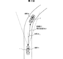
図2は本発明装置の一実施例を示す図である。図3(a)は、本発明における距離に対する自車速度と先行車速度の例を示した図であり、図3(b)は従来の車間距離制御装置での自車速度と先行車速度の例を示した図である。図2において、自車1は先行車2に追従走行している。自車1に搭載されているレーダ装置10で、先行車2までの距離R1と相対速度Rd1と方向θ1 を計測する。
FIG. 2 is a view showing an embodiment of the apparatus of the present invention. FIG. 3 (a) is a diagram showing an example of the own vehicle speed and the preceding vehicle speed with respect to the distance in the present invention, and FIG. 3 (b) shows the own vehicle speed and the preceding vehicle speed in the conventional inter-vehicle distance control device. It is the figure which showed the example. In FIG. 2, the
図3(b)に示す従来の車間距離制御の場合、同一時刻における先行車の速度と自車速度を同じとするよう自車の速度制御を実施するため、時刻t3における先行車と自車の速度はV1でほぼ等しくなる。しかし、時刻t3で先行車は地点P3を走行中であり、自車が地点P3を走行する時刻t4では、自車速度はV4となるため、地点P3の走行速度で比較すると、先行車と自車の間に(V3−V4)の速度差が発生する。 In the case of the conventional inter-vehicle distance control shown in FIG. 3B, the speed control of the host vehicle is performed so that the speed of the preceding vehicle and the host vehicle speed at the same time are the same. The speed is approximately equal at V1. However, since the preceding vehicle is traveling at point P3 at time t3, and the own vehicle speed is V4 at time t4 when the host vehicle travels at point P3, comparing with the traveling speed at point P3, A speed difference of (V3-V4) occurs between cars.
一方、図3(a)に示す本発明の例の場合、まず、先行車が地点P1を、速度V1で走行する時刻t1において、自車は地点Q1を走行中であり、先行車と自車の車間距離は、地点P1と地点Q1間の距離に等しくなる。なお、先行車速度は、自車速度と相対速度から求められる。目標車速・加速度演算部17で、時刻t1における自車速度と先行車速度V1の差から、自車が地点P1に到達する時点での自車側が、先行車がP1を通過したときの速度V1となるよう、目標車速と目標加速度を演算する。これら目標車速と目標加速度に基づいて、車両制御部18は、スロットルコントローラ21,変速機コントローラ
22,ブレーキコントローラ23のアクチュエータコントローラへ指令値を送り、減速させ、自車が地点P1を走行するときの速度をV1とする。同様に、先行車が加速している場合、図3(a)に示すように、先行車が地点P2を時刻t2に速度V2で走行している時に、自車は地点Q2を走行中である。時刻t2における自車速度と先行車速度V2との差から、目標車速・加速度演算部17で目標車速と目標加速度を演算する。これら目標車速と目標加速度に基づいて、車両制御部18は、スロットルコントローラ21,変速機コントローラ22に指令値を送り、自車が地点P2に到達した時点で、先行車が地点P2を通過した速度V2となるよう、加速する。
On the other hand, in the example of the present invention shown in FIG. 3A, first, at time t1 when the preceding vehicle travels at the point P1 at the speed V1, the own vehicle is traveling at the point Q1, and the preceding vehicle and the own vehicle Is equal to the distance between the point P1 and the point Q1. The preceding vehicle speed is obtained from the own vehicle speed and the relative speed. In the target vehicle speed /
図4は、主制御装置20が実行する走行制御のルーチンの一例を示すフローチャートである。スイッチ13で車速制御走行モードに設定されていることをステップ100で判定する。ステップ101で自車速を計測し、ステップ110でレーダ装置10が先行車を捕捉中であるかを判定する。レーダ装置10が先行車を捕捉していない場合は、目標とする車速を維持する走行制御をステップ111で実行する。先行車をレーダが捕捉している場合、ステップ102で先行車までの車間距離・相対速度・方向を計測する。次に、追従走行している先行車の方向が、あるしきい値以上であることをステップ103で判定する。先行車方向がしきい値以上の場合、すなわち、先行車が自車正面方向からある角度偏差している場合に、先行車車速をステップ104で求め、その先行車位置に自車が到達したときに、自車速度が、検出した先行車速度以下となるよう、目標加速度と目標速度をステップ105で求める。また、ステップ103で、追従対象の先行車が自車の正面方向にあると判定された場合は、ステップ107で、自車速度,車間距離,相対速度の関係から、適当な車間距離(例えば、自車速で2秒進む距離)を実現するための、目標車速と目標加速度を求める。これらの目標速度と目標加速度の値に基づいて、主制御装置20は、スロットルコントローラ21,変速機コントローラ22,ブレーキコントローラ23へ、目標値を実現するための指令値を出力する。また、図4に示した例の場合、ステップ102実行後に先行車方向の変化率を求めておき、ステップ103において、追従対象の先行車の方向の変化率がしきい値以上であるかを判断しても同様の走行制御が可能である。
FIG. 4 is a flowchart showing an example of a travel control routine executed by
次の走行制御ルーチンの一例につき図5で説明する。ステップ105までは図4に示した走行制御のフローと同一である。ステップ105で、目標加速度と目標速度を求めた後、ステップ102で計測した車間距離、及び、制御実施後に予想される車間距離のどちらかが、あるしきい値以上であることをステップ108で判定する。車間距離がしきい値以上で、十分な車間距離が確保されていると判断された場合は、ステップ106で、各コントローラへ、目標車速と目標加速度に基づく指令値を出力する。ステップ108で、車間距離がしきい値以下と判定されたときは、車間距離がしきい値以上となるように、目標車速と目標加速度の値をステップ109で減じて、これらの値をステップ106へ引き渡す。ステップ106では、目標車速と目標加速度の値に基づいて、各アクチュエータコントローラへ、目標値を実現するための指令値を出力する。
An example of the next travel control routine will be described with reference to FIG. The flow up to
自車のヨーレイトも計測する場合の制御ルーチンの一例を図6で説明する。ステップ
100で車速制御走行モードであると判断した後、ステップ120で自車速とヨーレイトを計測する。図4に示した例と同様に、ステップ110でレーダ装置10が先行車を捕捉中であるかを判定し、レーダ装置10が先行車を捕捉していない場合は、目標とする車速を維持する走行制御をステップ111で実行する。先行車をレーダが捕捉している場合、ステップ102で車間距離・相対速度・方向を計測する。次に、自車のヨーレイトがしきい値以上であるかをステップ121で判定する。ヨーレイトがしきい値以上、すなわち自車が旋回中であると判断された場合、自車速と相対速度から先行車車速をステップ104で求め、ステップ105において、自車がステップ102で計測した時点の先行車位置に到達したときに自車速度が検出した先行車速度以下となるよう、目標加速度と目標速度をステップ105で算出する。次にステップ122においては、ステップ105で求めた目標速度がヨーレイトから定まる上限速度以下であるかを判定し、上限速度以上である場合は、上限速度以下となるように目標車速と目標加速度をステップ123で再設定する。これら目標車速と目標加速度の値に基づいて、ステップ106では各アクチュエータコントローラへ目標値を実現するための指令値を出力する。
An example of a control routine for measuring the yaw rate of the host vehicle will be described with reference to FIG. After determining in
次に、カーブ走行中に先行車を見失った場合の制御ルーチンの一例を図7,図8,図9を用いて説明する。 Next, an example of a control routine for losing sight of a preceding vehicle during curve driving will be described with reference to FIGS.
図7に示したケースでは、自車1に搭載されているレーダ装置10で、先行車2までの距離R1と相対速度Rd1と方向θ1 、が計測でき、図8では、先行車2がレーダの計測範囲外に出ている。なお、これらの図でレーダの計測範囲を点線で示している。
In the case shown in FIG. 7, the
図9に、図7と図8で示した場合の制御フローの一例を示す。車速制御走行モードに設定されていることをステップ100で判定後、ステップ120で自車速とヨーレイトを計測し、先行車をレーダが捕捉しているかをステップ110で判定する。捕捉している場合は、ステップ102で車間距離・相対速度・方向を計測する。ステップ131で先行車の車速を演算し、記憶部16へ記憶する。次に、自車ヨーレイトがしきい値以上であるかをステップ121で判定し、ヨーレイトがしきい値以上、すなわち自車が旋回中であると判断された場合、ステップ102で計測した時点での先行車位置に到達したときに自車速度が検出した先行車速度と同一となるよう、ステップ105で目標加速度と目標速度を算出する。ステップ121で、ヨーレイトがしきい値以下であると判定された場合は、ステップ107で、自車速度,車間距離,相対速度の関係から、適当な車間距離(例えば、自車速で2秒進む距離)を実現するための、目標車速と目標加速度を求める。一方、ステップ110において、先行車を捕捉していないと判断されたときは、ステップ132で、最後に記憶した先行車速度を目標車速に設定し、ヨーレイトがしきい値以上の場合はステップ122へ、しきい値以下の場合は、ステップ106の処理へ進む。ステップ122においては、ステップ105やステップ107で求めた目標速度が、ヨーレイトから定まる上限速度以下であるかを判定し、上限速度以上である場合は、上限速度以下となるように目標車速と目標加速度をステップ123で再設定する。これら目標車速と目標加速度の値に基づいて、ステップ106では各アクチュエータコントローラへ目標値を実現するための指令値を出力する。
FIG. 9 shows an example of the control flow in the case shown in FIGS. After determining in
次に、レーダが複数車両を捕捉した場合の制御ルーチンの一例を図10〜図12を用いて説明する。図10に示したケースでは、自車1に搭載されているレーダ装置10で、先行車2の車間距離R1と相対速度Rd1と方向θ1 と、別の先行車3の車間距離R2と相対速度Rd2と方向θ2 を計測する。また、図11に示した例では、先行車2の更に前方にいる先行車4までの車間距離R3と相対速度Rd3と方向θ3 を計測している。
Next, an example of a control routine when the radar captures a plurality of vehicles will be described with reference to FIGS. In the case shown in FIG. 10, the
図12に制御フローの一例を示す。車速制御走行モードであると設定されていることをステップ100で判定後、ステップ101で自車速を計測する。ステップ110で、1台以上の先行車をレーダ装置10で捕捉していることを判定し、1台も先行車を捕捉していない場合は、ステップ111で車速維持走行を実施する。ステップ110で1台以上の先行車を捕捉している場合、ステップ143で先行車が2台以上であるかを判定する。先行車2台以上を捕捉していない場合、ステップ102で車間距離・相対速度,方向を計測後ステップ107へ進む。ステップ143で先行車が2台以上存在すると判定された場合、ステップ140で複数の先行車の車間距離・相対速度,方向を計測する。ステップ141において、追従している先行車のみならず、複数の先行車の方向が、あるしきい値以上であることを判定する。複数の先行車の方向がしきい値以上の場合、ステップ142で追従対象先行車を選択し、その車速を求める。ステップ105では、計測した時点の先行車位置に自車が到達したときに、自車速度が、検出した先行車速度以下となるよう、目標加速度と目標速度を求める。また、ステップ141で、複数の先行車の方向がしきい値以下であると判定された場合及び、ステップ143で先行車が1台と判定された場合は、ステップ107で、自車速と、追従対象先行車までの車間距離,相対速度の関係から、適当な車間距離を実現するための、目標車速と目標加速度を求める。これらの目標速度と目標加速度の値に基づいて、主制御装置20は、スロットルコントローラ21,変速機コントローラ22,ブレーキコントローラ23へ、目標値を実現するための指令値をステップ106で出力する。
FIG. 12 shows an example of the control flow. After determining in
次に、自車から見た先行車の相対的な速度ベクトルを算出して、自車の速度制御を行う手段について、図13〜図15を用いて説明する。 Next, means for calculating the relative speed vector of the preceding vehicle viewed from the own vehicle and controlling the speed of the own vehicle will be described with reference to FIGS.
図13は、先行車の速度ベクトルとヨーレイトを求める方法を図示している。自車1の正面方向をY軸とし、レーダ位置でY軸と直行する方向をX軸とする。レーダで計測した車間距離と方向から、先行車の自車から見た相対的位置座標(x,y)が求められる。これの時間微分をとることで、相対的な速度ベクトルを、車間距離R,相対速度Rd,方向θ,方向θの時間微分の関数として求めることができ、また、相対的速度ベクトルの極座標表示として、先行車の速度ベクトルの方向φが求められる。この結果、自車1から見た先行車の相対的ヨーレイトωを、速度ベクトルの成分と、各成分の微分値の関数として求めることができる。先行車の速度ベクトルとヨーレイトを求めて自車の速度制御を行う場合の制御フローの一例を図14に示す。ステップ102までは図9に示した実施例と同じフローである。ステップ150で、先行車の相対的な速度ベクトルを演算する。
FIG. 13 illustrates a method for obtaining the speed vector and yaw rate of the preceding vehicle. The front direction of the
先行車の速度ベクトルの変化から求められる相対的なヨーレイトと、自車のヨーレイトの和から、先行車のヨーレイトをステップ151で演算する。先行車のヨーレイトがあるしきい値以上であるかをステップ152で判断し、ヨーレイトがしきい値以上である場合は、ステップ105で、先行車位置に自車が到達したときに、自車速度が検出した先行車速度と同一となるよう、目標加速度と目標速度を求める。また、しきい値以下であると判定された場合は、自車速と、追従対象先行車までの車間距離,相対速度の関係から、適当な車間距離を実現するための、目標車速と目標加速度を求める。これらの目標速度と目標加速度の値に基づいて、ステップ106で主制御装置20は、各目標値を実現するための指令値を、各アクチュエータコントローラへ出力する。
In
次の速度ベクトルを利用する場合の実施例について、図15を用いて説明する。図15では、ステップ151まで図13と同じフローで、先行車の速度ベクトルを算出する。ステップ153では、ステップ102で計測した時点の先行車位置に自車が到達するまで、待つ。計測時点の先行車位置に自車が到達した時点で、自車のヨーレイトをステップ154で計測する。ステップ151で算出した先行車のヨーレイトと、ステップ154で計測した自車のヨーレイトの差が、あるしきい値以上であるかをステップ155で判定する。ステップ155でしきい値以上であると判定された場合、先行車の進む方向と、自車の進む方向が異なるため、今までの追従対象先行車に追従することを中止する。ステップ155で、先行車のヨーレイトと自車のヨーレイトの差がしきい値以下であると判定された場合は、ステップ160で、自車速,車間距離,相対速度,方向,ヨーレイト等の情報から、目標車速と目標車間距離をステップ160で求め、これら目標値に基づき、各アクチュエータへの指令値をステップ106で出力する。
An embodiment in which the next velocity vector is used will be described with reference to FIG. In FIG. 15, the speed vector of the preceding vehicle is calculated in the same flow as in FIG. 13 until
次にナビゲーション装置からの道路情報を利用する場合の実施例について、図16に示す。ステップ104までは図4に示した例と同じである。ステップ160で、主制御装置20はナビゲーション装置30から、現在位置における道路情報を入力する。この道路情報から、自車及び先行車位置周辺の道路に分岐が存在するかをステップ161で判定する。道路に分岐が存在しない場合は、ステップ105で、計測した時点の先行車位置に自車が到達したときに、自車速度が、検出した先行車速度以下となるよう、目標加速度と目標速度を求める。また、ステップ161で道路に分岐が存在しないと判定されたときは、ステップ107で、自車速と、追従対象先行車までの車間距離,相対速度の関係から、適当な車間距離を実現するための、目標車速と目標加速度を求める。これらの目標速度と目標加速度の値に基づいて、主制御装置20は、スロットルコントローラ21,変速機コントローラ22,ブレーキコントローラ23へ、目標値を実現するための指令値をステップ
106で出力する。
Next, FIG. 16 shows an embodiment in which road information from the navigation device is used. The process up to step 104 is the same as the example shown in FIG. In
以上説明したように、本実施例によれば、ある地点を通過する先行車の速度を記憶して、自車がその地点を通過するときには、記憶した先行車の速度以下で走行することで、自車のカーブ進入速度を先行車のカーブ進入速度以下とするよう制御することができ、道路形状に合ったドライバーに違和感の少ない速度制御ができる。また、自車のヨーレイトに合わせて上限速度を設定することで、横方向加速度をある値以下にでき、乗り心地を向上できる。また、先行車の速度ベクトルを推定しながら走行することで、カーブが連続するような複雑な形状の道路で先行車追従走行を行う場合でも、道路形状にあった違和感のない速度制御ができる。 As described above, according to the present embodiment, the speed of the preceding vehicle passing through a certain point is stored, and when the own vehicle passes through that point, by traveling below the stored preceding vehicle speed, It is possible to control the vehicle's curve approach speed to be equal to or lower than the preceding vehicle's curve approach speed, and to perform speed control with less discomfort to the driver that matches the road shape. In addition, by setting the upper limit speed according to the yaw rate of the host vehicle, the lateral acceleration can be reduced to a certain value or less, and the riding comfort can be improved. Further, by traveling while estimating the speed vector of the preceding vehicle, speed control can be performed without a sense of incongruity according to the road shape even when the preceding vehicle follows traveling on a road having a complicated shape with continuous curves.
10 レーダ装置10 Radar equipment
11 車速センサ11 Vehicle speed sensor
12 ヨーレイトセンサ12 Yaw rate sensor
13 スイッチ13 switches
20 主制御装置20 Main controller
16 記憶部16 Memory unit
24 スロットル24 throttle
26 変速機26 Transmission
27 ブレーキアクチュエータ27 Brake actuator
Claims (5)
自車の車速を検出する手段と、
前記自車速度と前記相対速度から前記先行車の速度を演算する手段と、
前記先行車が前記自車の正面方向からある角度偏向した地点を通過する前記先行車の速度を記憶し、前記自車がその地点を通過するときに、記憶した前記先行車の速度以下となるように、スロットル,トランスミッション,ブレーキの少なくとも1つを用いて自車速度を制御する手段と、を備えた自動車の走行制御装置。 Means for detecting the inter-vehicle distance and relative speed with the preceding vehicle;
Means for detecting the speed of the vehicle;
Means for calculating the speed of the preceding vehicle from the host vehicle speed and the relative speed;
The speed of the preceding vehicle that passes through a point deflected by an angle from the front direction of the host vehicle is stored, and when the host vehicle passes through that point, the speed is equal to or less than the stored speed of the preceding vehicle. And a means for controlling the speed of the vehicle using at least one of a throttle, a transmission, and a brake.
前記制御手段は、前記先行車の方向が変化した場合に前記自車速度を制御する自動車の走行制御装置。 The vehicle travel control device according to claim 1,
The control means, the travel control device for vehicles wherein that controls the vehicle speed when the direction of the preceding vehicle has changed.
前記制御手段は、前記先行車との車間距離が所定の値以上に前記自車速度を制御する自動車の走行制御装置。 The vehicle travel control device according to claim 1,
Wherein, the preceding vehicle and the travel control device following distance of vehicles that control the vehicle speed above a predetermined value.
自車の車速とヨーレイトを検出する手段と、
前記自車のヨーレイトがある値以上の場合に、ある地点を通過する前記先行車の速度を記憶し、前記自車がその地点を通過するときに、前記自車のヨーレイトの大きさに基づいて決められる速度と記憶した前記先行車の速度以下となるようにスロットル,トランスミッション,ブレーキの少なくとも1つを用いて自車速度を制御する手段と、を備えた自動車の走行制御装置。 The vehicle travel control device according to claim 1,
Means for detecting the vehicle speed and yaw rate of the vehicle ;
If the above is the yaw rate of the previous SL vehicle value, and stores the speed of said preceding vehicle passing a given point, the when the vehicle passes through the point, based on the magnitude of the yaw rate of the vehicle And a means for controlling the vehicle speed using at least one of a throttle, a transmission, and a brake so as to be equal to or less than the speed of the preceding vehicle stored in advance.
自車の車速とヨーレイトを検出する手段と、
前記先行車を見失い、かつ、前記自車のヨーレイトがある値以上の場合には、前記先行車を見失った時点の前記先行車の速度と前記自車のヨーレイトの大きさに基づいて決められる速度以下になるように、スロットル,トランスミッション,ブレーキの少なくとも1つを用いて自車速度を制御する手段と、を備えた自動車の走行制御装置。 The vehicle travel control device according to claim 1,
Means for detecting the vehicle speed and yaw rate of the vehicle ;
Lose sight of pre SL preceding vehicle, and wherein when more than a certain value yaw rate of the vehicle is determined based on the size of the yaw rate of said preceding vehicle speed and the vehicle at the time of sight of the preceding vehicle And a means for controlling the vehicle speed using at least one of a throttle, a transmission, and a brake so as to be lower than the speed.
Applications Claiming Priority (1)
| Application Number | Priority Date | Filing Date | Title |
|---|---|---|---|
| PCT/JP1997/004375 WO1999028144A1 (en) | 1997-12-01 | 1997-12-01 | Running controller for automobile |
Related Child Applications (1)
| Application Number | Title | Priority Date | Filing Date |
|---|---|---|---|
| JP2007010941A Division JP4277907B2 (en) | 2007-01-22 | 2007-01-22 | Driving control device for automobile |
Publications (1)
| Publication Number | Publication Date |
|---|---|
| JP3932806B2 true JP3932806B2 (en) | 2007-06-20 |
Family
ID=14181560
Family Applications (1)
| Application Number | Title | Priority Date | Filing Date |
|---|---|---|---|
| JP2000523076A Expired - Fee Related JP3932806B2 (en) | 1997-12-01 | 1997-12-01 | Driving control device for automobile |
Country Status (5)
| Country | Link |
|---|---|
| US (2) | US6363311B1 (en) |
| EP (2) | EP1034963B1 (en) |
| JP (1) | JP3932806B2 (en) |
| DE (2) | DE69739064D1 (en) |
| WO (1) | WO1999028144A1 (en) |
Families Citing this family (56)
| Publication number | Priority date | Publication date | Assignee | Title |
|---|---|---|---|---|
| US6212465B1 (en) * | 1999-12-22 | 2001-04-03 | Visteon Global Technologies Inc. | Method and system for controlling vehicle speed based on vehicle yaw rate and yaw acceleration |
| DE10018557A1 (en) | 2000-04-14 | 2001-10-18 | Bosch Gmbh Robert | Regulating vehicle speed involves applying acceleration or acceleration change limit if in addition to/instead of transverse acceleration, preceding vehicle reaches radar sensing range limit |
| DE10018556A1 (en) * | 2000-04-14 | 2001-10-18 | Bosch Gmbh Robert | Regulating vehicle speed involves determining course offsets of preceding vehicle in cycles, delaying by defined time, deriving historical course offset from curvature of vehicle trajectory |
| DE10030258A1 (en) * | 2000-06-20 | 2002-01-03 | Daimler Chrysler Ag | Method for controlling the distance of a vehicle from a preceding vehicle and distance control system |
| JP3646660B2 (en) * | 2001-03-26 | 2005-05-11 | 日産自動車株式会社 | Vehicle tracking control device |
| DE10118265A1 (en) | 2001-04-12 | 2002-10-17 | Bosch Gmbh Robert | Detecting vehicle lane change, involves forming track change indicating signal by comparing measured angular rate of preceding vehicle(s) with vehicle's own yaw rate |
| JP2003072416A (en) * | 2001-08-31 | 2003-03-12 | Denso Corp | Vehicular travel control device |
| DE10159658A1 (en) * | 2001-12-05 | 2003-06-26 | Daimler Chrysler Ag | System for automatically following a motor vehicle |
| US6679702B1 (en) * | 2001-12-18 | 2004-01-20 | Paul S. Rau | Vehicle-based headway distance training system |
| FR2834110B1 (en) * | 2001-12-20 | 2004-01-30 | Valeo Vision | DRIVING ASSISTANCE DEVICE FOR SYNERGY-OPTIMIZED MOTOR VEHICLE WITH ADAPTIVE LIGHTING |
| US7260465B2 (en) * | 2002-04-30 | 2007-08-21 | Ford Global Technology, Llc | Ramp identification in adaptive cruise control |
| US6753804B2 (en) | 2002-05-21 | 2004-06-22 | Visteon Global Technologies, Inc. | Target vehicle identification based on the theoretical relationship between the azimuth angle and relative velocity |
| DE10251037A1 (en) * | 2002-11-02 | 2004-05-19 | Robert Bosch Gmbh | Device for adaptive distance and speed regulation with jolt limiting has dynamic device that detects sudden changes in detected traffic situation, restricts operation of jolt limiter depending on situation |
| DE10254420A1 (en) * | 2002-11-21 | 2004-06-03 | Lucas Automotive Gmbh | System for influencing the speed of a motor vehicle |
| DE10254394A1 (en) * | 2002-11-21 | 2004-06-03 | Lucas Automotive Gmbh | System for influencing the speed of a motor vehicle |
| US7386385B2 (en) * | 2002-11-21 | 2008-06-10 | Lucas Automotive Gmbh | System for recognising the lane-change manoeuver of a motor vehicle |
| US6691018B1 (en) * | 2002-11-21 | 2004-02-10 | Visteon Global Technologies, Inc. | Method and system for identifying a lane change |
| DE10254421A1 (en) * | 2002-11-21 | 2004-06-03 | Lucas Automotive Gmbh | System for influencing the speed of a motor vehicle |
| US7831367B2 (en) * | 2002-11-21 | 2010-11-09 | Lucas Automotive Gmbh | System for influencing the speed of a motor vehicle |
| DE10254423A1 (en) * | 2002-11-21 | 2004-06-03 | Lucas Automotive Gmbh | System for influencing the speed of a motor vehicle |
| US7162361B2 (en) * | 2002-11-21 | 2007-01-09 | Lucas Automotive Gmbh | System for influencing the speed of a motor vehicle |
| DE10254424A1 (en) * | 2002-11-21 | 2004-06-03 | Lucas Automotive Gmbh | System for influencing the speed of a motor vehicle |
| DE10254403A1 (en) * | 2002-11-21 | 2004-06-03 | Lucas Automotive Gmbh | System for influencing the speed of a motor vehicle |
| DE10254402B4 (en) * | 2002-11-21 | 2011-02-17 | Lucas Automotive Gmbh | System for influencing the speed of a motor vehicle |
| US7831368B2 (en) * | 2002-11-21 | 2010-11-09 | Lucas Automotive Gmbh | System for influencing the speed of a motor vehicle |
| KR100513523B1 (en) * | 2003-05-29 | 2005-09-07 | 현대자동차주식회사 | Autonomous intelligent cruise control device |
| DE10326431A1 (en) * | 2003-06-10 | 2005-01-13 | Daimlerchrysler Ag | Device and method for determining the position of objects in the environment of a vehicle |
| JP2005147292A (en) * | 2003-11-17 | 2005-06-09 | Toyota Motor Corp | Shift control device for transmission and shift control method of transmission |
| JP4639997B2 (en) * | 2005-02-18 | 2011-02-23 | トヨタ自動車株式会社 | Vehicle deceleration control device |
| JP3925540B2 (en) * | 2005-03-23 | 2007-06-06 | トヨタ自動車株式会社 | Vehicle travel control device |
| JP4792248B2 (en) * | 2005-06-30 | 2011-10-12 | 日立オートモティブシステムズ株式会社 | Travel control device, travel control system, and navigation information recording medium storing information used for the travel control |
| JP4434101B2 (en) * | 2005-08-03 | 2010-03-17 | トヨタ自動車株式会社 | Vehicle driving force control device |
| US20080255745A1 (en) * | 2005-08-29 | 2008-10-16 | Wolfgang Bay | Method and Device for Controlling an Electronic Brake of a Vehicle |
| DE102005048522B4 (en) * | 2005-10-07 | 2016-08-04 | Volkswagen Ag | Method and device for controlling an automatic transmission |
| SE528567C2 (en) * | 2005-12-13 | 2006-12-19 | Scania Cv Abp | Data generating system for adaptive cruise control method in vehicle, measures distance to vehicle in front repeatedly when driving around bend |
| JP4856525B2 (en) * | 2006-11-27 | 2012-01-18 | 富士重工業株式会社 | Advance vehicle departure determination device |
| JP4967806B2 (en) * | 2007-05-22 | 2012-07-04 | 株式会社日立製作所 | Vehicle speed control device according to path curvature |
| JP2010003013A (en) * | 2008-06-18 | 2010-01-07 | Aisin Aw Co Ltd | Driving support device, driving support method and driving support program |
| US8311720B2 (en) * | 2009-01-09 | 2012-11-13 | Robert Bosch Gmbh | Lost target function for adaptive cruise control |
| JP5311286B2 (en) * | 2009-03-31 | 2013-10-09 | 株式会社エクォス・リサーチ | Vehicle control apparatus, vehicle, and vehicle control program |
| JP5234429B2 (en) * | 2009-03-31 | 2013-07-10 | 株式会社エクォス・リサーチ | Vehicle control apparatus, vehicle, and vehicle control program |
| CN102460535B (en) * | 2009-06-11 | 2014-09-03 | 丰田自动车株式会社 | Method for judging vehicle traveling position and vehicle traveling position judgment device |
| JP5363906B2 (en) * | 2009-08-05 | 2013-12-11 | 株式会社アドヴィックス | Vehicle speed control device |
| WO2012091637A1 (en) * | 2010-12-29 | 2012-07-05 | Volvo Lastvagnar Ab | X adaptative cruise control |
| KR101245100B1 (en) * | 2011-06-20 | 2013-03-25 | 주식회사 만도 | Smart cruise control system and control method thereof |
| JP6363517B2 (en) * | 2015-01-21 | 2018-07-25 | 株式会社デンソー | Vehicle travel control device |
| JP6252548B2 (en) * | 2015-05-22 | 2017-12-27 | トヨタ自動車株式会社 | Vehicle speed limiting device and vehicle speed control device |
| US10183684B2 (en) * | 2016-03-31 | 2019-01-22 | General Electric Company | Multiple vehicle control system |
| WO2018106575A1 (en) * | 2016-12-05 | 2018-06-14 | Cummins Inc. | Multi-vehicle load delivery management systems and methods |
| JP6843665B2 (en) | 2017-03-24 | 2021-03-17 | 日立Astemo株式会社 | Automatic operation control device |
| GB2560980B (en) * | 2017-03-31 | 2019-04-17 | Ford Global Tech Llc | A method and system for a motor vehicle |
| CN107253480B (en) * | 2017-06-23 | 2019-10-25 | 北京新能源汽车股份有限公司 | Control method for vehicle and system |
| CA3073798C (en) | 2017-08-24 | 2021-05-04 | Nissan Motor Co., Ltd. | Method and device for controlling travel of drive-assisted vehicle |
| US11097600B2 (en) * | 2017-08-25 | 2021-08-24 | Thermo King Corporation | Method and system for adaptive power engine control |
| FR3093305B1 (en) | 2019-02-28 | 2021-01-29 | Psa Automobiles Sa | REGULATING THE SPEED OF A VEHICLE WHEN OTHING IN A CORNER |
| DE102021203786A1 (en) * | 2021-04-16 | 2022-10-20 | Volkswagen Aktiengesellschaft | Method for operating a driver assistance system and vehicle with a driver assistance system |
Family Cites Families (22)
| Publication number | Priority date | Publication date | Assignee | Title |
|---|---|---|---|---|
| JPS5843009A (en) | 1981-09-07 | 1983-03-12 | Toyota Motor Corp | Automatic speed controller of automobile |
| JPS6130428A (en) | 1984-07-20 | 1986-02-12 | Nissan Motor Co Ltd | Controller for vehicle travelling |
| JPS61162776A (en) * | 1985-01-14 | 1986-07-23 | Nissan Motor Co Ltd | Radar for vehicle |
| JP2648309B2 (en) | 1987-10-28 | 1997-08-27 | 富士通テン株式会社 | Vehicle control system |
| JPH036473A (en) | 1989-06-02 | 1991-01-11 | Mitsubishi Electric Corp | Apparatus for testing electrostatic breakdown of semiconductor device |
| JP2803756B2 (en) | 1989-09-29 | 1998-09-24 | マツダ株式会社 | Travel control device for mobile vehicles |
| JPH0620649A (en) | 1992-07-03 | 1994-01-28 | Toto Ltd | Translucent bulb of metal-vapor discharge lamp and manufacture thereof |
| JP3070277B2 (en) | 1992-08-04 | 2000-07-31 | 日産自動車株式会社 | Preceding vehicle detection device |
| JPH06150200A (en) | 1992-11-06 | 1994-05-31 | Toyota Motor Corp | Travelling controller for vehicle |
| JP3125496B2 (en) * | 1993-01-12 | 2001-01-15 | トヨタ自動車株式会社 | Travel control device for vehicles |
| JPH06320986A (en) | 1993-05-19 | 1994-11-22 | Mazda Motor Corp | Vehicle speed control device |
| US5572449A (en) * | 1994-05-19 | 1996-11-05 | Vi&T Group, Inc. | Automatic vehicle following system |
| SE516317C2 (en) * | 1994-06-07 | 2001-12-17 | Saabtech Electronics Ab | Procedure for determining the lane of a vehicle ahead |
| JPH08192661A (en) | 1995-01-20 | 1996-07-30 | Mitsubishi Motors Corp | Running control device of vehicle |
| JPH08240658A (en) | 1995-03-06 | 1996-09-17 | Fujitsu Ten Ltd | Radar apparatus |
| JP3457441B2 (en) * | 1995-10-31 | 2003-10-20 | 本田技研工業株式会社 | How to control an autonomous vehicle |
| JP3331882B2 (en) * | 1995-12-27 | 2002-10-07 | 株式会社デンソー | Central axis deflection amount calculating device, central axis deflection amount correcting device, and inter-vehicle control device of vehicle obstacle detection device |
| DE19722947C1 (en) * | 1997-05-31 | 1999-02-25 | Bosch Gmbh Robert | Method and device for determining a future course range of a vehicle |
| DE19728591A1 (en) * | 1997-07-04 | 1999-01-21 | Audi Ag | Method for determining the driving behavior of a vehicle in front |
| DE19736964B4 (en) * | 1997-08-25 | 2011-01-20 | Continental Automotive Gmbh | Method for determining a controlled object |
| DE19736966C2 (en) * | 1997-08-25 | 1999-08-05 | Mannesmann Vdo Ag | Method and arrangement for determining a control object |
| US5959569A (en) * | 1997-10-09 | 1999-09-28 | Eaton Vorad Technologies, L.L.C. | Method and apparatus for in path target determination for an automotive vehicle using a gyroscopic device |
-
1997
- 1997-12-01 EP EP97913481A patent/EP1034963B1/en not_active Expired - Lifetime
- 1997-12-01 DE DE69739064T patent/DE69739064D1/en not_active Expired - Fee Related
- 1997-12-01 US US09/555,480 patent/US6363311B1/en not_active Expired - Fee Related
- 1997-12-01 WO PCT/JP1997/004375 patent/WO1999028144A1/en active IP Right Grant
- 1997-12-01 EP EP06003790A patent/EP1674322B1/en not_active Expired - Lifetime
- 1997-12-01 JP JP2000523076A patent/JP3932806B2/en not_active Expired - Fee Related
- 1997-12-01 DE DE69735957T patent/DE69735957T2/en not_active Expired - Fee Related
-
2001
- 2001-10-09 US US09/971,639 patent/US6473685B2/en not_active Expired - Lifetime
Also Published As
| Publication number | Publication date |
|---|---|
| EP1034963A1 (en) | 2000-09-13 |
| EP1674322A1 (en) | 2006-06-28 |
| US6473685B2 (en) | 2002-10-29 |
| EP1034963B1 (en) | 2006-05-24 |
| WO1999028144A1 (en) | 1999-06-10 |
| DE69735957T2 (en) | 2006-11-23 |
| US6363311B1 (en) | 2002-03-26 |
| DE69735957D1 (en) | 2006-06-29 |
| US20020032514A1 (en) | 2002-03-14 |
| EP1674322B1 (en) | 2008-10-22 |
| DE69739064D1 (en) | 2008-12-04 |
| EP1034963A4 (en) | 2002-10-23 |
Similar Documents
| Publication | Publication Date | Title |
|---|---|---|
| JP3932806B2 (en) | Driving control device for automobile | |
| JP6376059B2 (en) | Control device for autonomous driving vehicle | |
| US11809194B2 (en) | Target abnormality determination device | |
| JP6237685B2 (en) | Vehicle control device | |
| JP4277907B2 (en) | Driving control device for automobile | |
| JP4781707B2 (en) | Vehicle driving support device | |
| EP1818231B1 (en) | Vehicle control system | |
| JP7172257B2 (en) | Autonomous driving system | |
| CN107107751B (en) | Target vehicle speed generation device and travel control device | |
| EP2712780B1 (en) | Method and apparatus for performing driving assistance | |
| JP5899664B2 (en) | Vehicle acceleration suppression device and vehicle acceleration suppression method | |
| US20090143951A1 (en) | Forward Collision Avoidance Assistance System | |
| US10759425B2 (en) | Autonomous driving system | |
| JP6680403B2 (en) | Target vehicle speed generation method and target vehicle speed generation device for driving support vehicle | |
| JP5023869B2 (en) | VEHICLE DRIVE OPERATION SUPPORT DEVICE AND VEHICLE DRIVE OPERATION SUPPORT METHOD | |
| US9914453B2 (en) | Method for predicting the travel path of a motor vehicle and prediction apparatus | |
| JP4134885B2 (en) | Curve estimation device and travel control device using the same | |
| JPH11321379A (en) | Vehicle running control device | |
| JP6558261B2 (en) | Automatic driving device | |
| JP2019209701A (en) | Vehicle control device and vehicle control method | |
| JP4576922B2 (en) | Vehicle travel control device | |
| JP2013049425A (en) | Vehicle acceleration control device and method | |
| US20230382387A1 (en) | Driving Control Method and Driving Control Device | |
| JPH05107355A (en) | Vehicle running controller | |
| JP2005035416A (en) | Driving operation assisting device for vehicle and vehicle equipped with driving operation assisting device for vehicle |
Legal Events
| Date | Code | Title | Description |
|---|---|---|---|
| A621 | Written request for application examination |
Free format text: JAPANESE INTERMEDIATE CODE: A621 Effective date: 20040426 |
|
| RD01 | Notification of change of attorney |
Free format text: JAPANESE INTERMEDIATE CODE: A7421 Effective date: 20060418 |
|
| A131 | Notification of reasons for refusal |
Free format text: JAPANESE INTERMEDIATE CODE: A131 Effective date: 20061121 |
|
| A521 | Request for written amendment filed |
Free format text: JAPANESE INTERMEDIATE CODE: A523 Effective date: 20070122 |
|
| TRDD | Decision of grant or rejection written | ||
| A01 | Written decision to grant a patent or to grant a registration (utility model) |
Free format text: JAPANESE INTERMEDIATE CODE: A01 Effective date: 20070227 |
|
| A61 | First payment of annual fees (during grant procedure) |
Free format text: JAPANESE INTERMEDIATE CODE: A61 Effective date: 20070312 |
|
| FPAY | Renewal fee payment (event date is renewal date of database) |
Free format text: PAYMENT UNTIL: 20110330 Year of fee payment: 4 |
|
| FPAY | Renewal fee payment (event date is renewal date of database) |
Free format text: PAYMENT UNTIL: 20110330 Year of fee payment: 4 |
|
| S111 | Request for change of ownership or part of ownership |
Free format text: JAPANESE INTERMEDIATE CODE: R313111 |
|
| FPAY | Renewal fee payment (event date is renewal date of database) |
Free format text: PAYMENT UNTIL: 20110330 Year of fee payment: 4 |
|
| R350 | Written notification of registration of transfer |
Free format text: JAPANESE INTERMEDIATE CODE: R350 |
|
| FPAY | Renewal fee payment (event date is renewal date of database) |
Free format text: PAYMENT UNTIL: 20110330 Year of fee payment: 4 |
|
| FPAY | Renewal fee payment (event date is renewal date of database) |
Free format text: PAYMENT UNTIL: 20120330 Year of fee payment: 5 |
|
| FPAY | Renewal fee payment (event date is renewal date of database) |
Free format text: PAYMENT UNTIL: 20130330 Year of fee payment: 6 |
|
| FPAY | Renewal fee payment (event date is renewal date of database) |
Free format text: PAYMENT UNTIL: 20130330 Year of fee payment: 6 |
|
| FPAY | Renewal fee payment (event date is renewal date of database) |
Free format text: PAYMENT UNTIL: 20140330 Year of fee payment: 7 |
|
| LAPS | Cancellation because of no payment of annual fees |