JP3932530B2 - Vacuum cleaner packing equipment - Google Patents
Vacuum cleaner packing equipment Download PDFInfo
- Publication number
- JP3932530B2 JP3932530B2 JP2002132482A JP2002132482A JP3932530B2 JP 3932530 B2 JP3932530 B2 JP 3932530B2 JP 2002132482 A JP2002132482 A JP 2002132482A JP 2002132482 A JP2002132482 A JP 2002132482A JP 3932530 B2 JP3932530 B2 JP 3932530B2
- Authority
- JP
- Japan
- Prior art keywords
- cushioning material
- vacuum cleaner
- partition wall
- central partition
- pieces
- Prior art date
- Legal status (The legal status is an assumption and is not a legal conclusion. Google has not performed a legal analysis and makes no representation as to the accuracy of the status listed.)
- Expired - Fee Related
Links
Images




Landscapes
- Electric Suction Cleaners (AREA)
- Packaging Of Machine Parts And Wound Products (AREA)
- Cartons (AREA)
- Buffer Packaging (AREA)
- Packages (AREA)
Description
【0001】
【発明の属する技術分野】
本発明は、電気掃除機の梱包装置に関するものである。
【0002】
【従来の技術】
この種電気掃除機の梱包装置の一例として、特開平9−182695号公報に記載された発明がある。この発明に係る電気掃除機の梱包装置は、発泡スチロールを一切使用することなく、再生可能な段ボールのみを使用して電気掃除機を梱包するようにしたものである。
【0003】
この梱包装置は、図15に示すように、掃除機本体60を、上面段ボールパット75、下面段ボールパット72及び周面段ボール71で包み込み、上面段ボールパット75上にホース61、吸込具64及び連結パイプ66を収納して、これらを外装箱70内に収納するようにしたものである。なお、下面段ボールパット72の前部には、ロ字形状の折曲片73が前面切曲片74と一体に形成され、掃除機本体60の吸気口60aに嵌め込まれるようになっている。
【0004】
このような梱包装置により電気掃除機を梱包するには、先ず、外装箱70の内面形状と同じ寸法の周面段ボールパット71を外装箱70内に挿入し、ついで、その中に周面段ボールパット71の内面形状と同じ寸法の下面段ボールパット72を挿入する。そして、掃除機本体60を下面段ボールのパット72内に、ロ字形状折曲げ片73を吸気口部60aに嵌め込んで収納する。最後に、上面段ボールパット75で掃除機本体60を押え込み、その上にホース61、吸込具64及び連結パイプ66を収納し、外装箱70を閉じることで電気掃除機が外装箱に梱包される。
【0005】
【発明が解決しようとする課題】
上記のような従来の電気掃除機の梱包装置においては、次のような問題がある。
(1)連結パイプ、ホース、吸込具などのアタッチメントを、上面段ボールパットの平面上に置いて同一平面、同一空間に収納しているため、これらが自由に動いて互いにぶつかり合って傷がつき易い。
(2)連結パイプを上面段ボールパットの長手方向にこれと平行に収納するようにしているので、梱包装置の長手方向の大きさが連結パイプの長さに規制され、コンパクト化が困難である。
【0006】
(3)緩衝材である下面段ボールパットを吸湿性の高い段ボール材で構成しているため、倉庫での積段時において外装箱の座屈が発生し易い。これを防止するため外装箱内に周面段ボールパットを挿入しなければならないので、コストアップになる。
(4)一般に、外装箱の手掛け部は、周壁に穴をあけて手を掛けるようにしているため強度的に問題があり、破れ易い。
【0007】
本発明は、上記の課題を解決するためになされたもので、梱包した連結パイプや吸込具などのアタッチメントが動いて傷がつくことがなく、強度が大幅に向上し、その上コンパクトでコストを低減できる段ボール材からなる電気掃除機の梱包装置を提供することを目的としたものである。
【0008】
【課題を解決するための手段】
(1)本発明は、掃除機本体、ホース、吸込具及び連結パイプを外装箱内に収納して梱包する電気掃除機の梱包装置において、前記外装箱内の一方の側に設置され、ホースの手元操作部収納部及び差込部収納部が設けられた第1の緩衝材と、前記外装箱内の他方の側に設置されて前記外装箱との間に吸込具収納部が形成され、前記第1の緩衝材との間に掃除機本体収納部が形成された第2の緩衝材と、前記第1、第2の緩衝材の上部に設置されたパイプ保持部材とを備え、前記第1の緩衝材を、幅方向を規制する中央仕切壁と、該中央仕切り壁の両側から後面側に折曲げられた連結片を介して前面側に折曲げられた両側壁片と、該両側壁片の前端部を内側に折曲げた前部保持片と、前記中央仕切壁の上端部に立設された上部保持片とによってほぼM字状に形成し、第2の緩衝材を、幅方向を規制する中央仕切壁と、該中央仕切壁の両側から前面側に折曲げられた連結片を介して後面側に折曲げられた両側壁片と、該両側壁片の後端部を内側に折曲げた後部保持片と、前記中央仕切壁の上端部に立設された上部保持片とによってほぼH字状に形成したものである。
【0009】
上記の第1の緩衝材の前部保持片と外装箱との間に手元操作部収納部を形成すると共に、該前部保持片と連結片との間に差込部収納部を形成した。
また、上記の第2の緩衝材の側壁に、切起しにより吸込具を挟持する吸込具固定部を設けた。
【0014】
【発明の実施の形態】
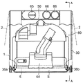
図1は本発明の一実施の形態に係る梱包装置により電気掃除機を梱包した状態を示す縦断面図、図2は図1の分解斜視図である。
【0015】
両図において、1は直方体状の外装箱、5は外装箱1の底部に設置される底部緩衝材である。10は平面ほぼM字状の第1の緩衝材(以下、前部緩衝材という)、30は平面ほぼH字状の第2の緩衝材(以下、後部緩衝材という)、50は断面ほぼコ字状のパイプ支持部材で、これら外装箱1、底部緩衝材5、前後の緩衝材10,30及びパイプ支持部材50は、再生可能な材料、すなわち段ボールによって形成されており、これらにより梱包装置を構成する。
【0016】
60は梱包装置に収納される電気掃除機の本体(以下、掃除機本体という)、61は蛇腹状のホースで、その一方の端部には掃除機本体60への差込部62が設けられており、他方の端部には手元操作部63が設けられている。64は吸込具であるT形ノズル、65は吸込具であるすき間ノズル、66は連結パイプである。
【0017】
次に、梱包装置について詳細に説明する。
外装箱1は、図2に示すように、段ボール材により直方体状に形成されており、周壁2の上端部にはそれぞれ蓋片3が設けられている。4a,4bは短辺側の対向する周壁2に設けられた切起し部の切起し片を内側上方に折曲げて周壁2を二重にし、パイプ支持部材50に当接させる手掛け部であり、両方に手を掛けて持ち上げるようにしたもので、手掛け部4a,4bをこのように構成することにより、持ち易くなり、強度が向上して外装箱1の破れ等を防止することができる。この外装箱1の長手方向の長さLは、連結パイプ66の長さより若干短かく形成されている。
【0018】
底部緩衝材5は、図3に示すように、フルートを長手方向にした段ボール材によりほぼ長方形に形成されており、載置部6とその3辺を折線8により折曲げて形成した高さh1の脚部7とを有し、長手方向の長さL1は外装箱1の内のり長さLより短かく、幅W1は外装箱1の内のり幅Wより若干狭く形成されてお、外装箱1内に設置したときは、脚部7と周壁2との間に僅かなすき間が形成される。なお、この底部緩衝材5は後述の前部緩衝材10の中央仕切壁11の下端部に一体に設けてもよく、場合によっては省略してもよい。
【0019】
図4に前部緩衝材10の展開図を、図5にその組立図を示す。図4に示すように、フルート方向を上下方向とした段ボール材の中央に設けた中央仕切壁11の上部中央部には上部保持片12が突設されており、その両側下方には折線21a,21bが設けられて両側に連結片13a,13bが形成され、下部両側には連結片13a,13bが折曲げできるようにL字状のスリットが設けられている。なお、この中央仕切壁11の高さh2は掃除機本体60の高さHとほぼ等しく形成されており、その幅W2は底部緩衝材5の幅W1とほぼ等しく形成されている。
【0020】
また、連結片13a,13bの両側には折線22a,22bを介して、外装箱1の内のり高さhとほぼ等しい高さh3で、上下が連結片13a,13bから突出した側壁片14a,14bが形成されており、さらにその両側には折線23a,23bを介して下縁部が連結片13a,13bの下縁部とほぼ等しい前部保持片15a,15bが設けられている。なお、以下の説明では、破線で示す線は組立に際して谷折りをするミシン目、スリット等を示し、一点鎖線で示す線は組立に際して山折りをするミシン目、スリット等を示す。また、以下の説明では、図の右側(例えば、図2)または上方(図9、図10、図12〜図14)を前部側、左側又は下方を後部側という。
【0021】
上記のような前部緩衝材10において、連結片13a,13bの上縁部と左右の側壁片14a,14bの上縁部との高さ差h4は、パイプ支持部材50の両端壁51a,51bの高さh6とほぼ等しく、連結片13a,13bの下縁部と左右側壁片14a,14bの下縁部との高さの差h5は、底部緩衝材5の脚部7の高さh1とほぼ等しい(図2、図3参照)。
【0022】
このように展開された前部緩衝材10を組立てるには、先ず、折線21a,21bにより連結片13a,13bを斜め外方で後部側に折曲げ、ついで折線22a,22bにより側壁片14a,14bを鋭角に前部側に折曲げたのち、折線23a,23bにより前部保持片15a,15bを内側にほぼ直角に折曲げる。このとき、中央仕切壁11の両端部は側壁片14a,14bの内面に当接する。最後に上部保持片12を折線24により前部側に折曲げれば、前部緩衝材10の組立が終了する。
【0023】
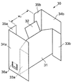
図6に後部緩衝材30の展開図を、図7にその組立図を示す。図6に示すように、フルート方向を上下方向とした段ボール材の中央に設けた中央仕切壁31の上部中央部には上部保持片32が突設されており、その両側は下方に向って傾斜したのち折線41a,41bを介して、その下端部が中央仕切壁31から突出した連結片33a,33bが設けられており、その両側には折線42a,42bを介して上縁部が上部保持片32の上縁部とほぼ等しく、下縁部が連結片33a,33bと等しい高さh3の側壁片34a,34bが設けられ、さらにその両側には、折線43a,43bを介して後部保持片35a,35bが設けられている。36a,36bは側壁片34a,34bの下部に設けられ、内側に切起こされて収容したT形ノズル64を保持する吸込具固定部である。
【0024】
上記のような後部緩衝材30の側壁片34a,34bの高さh3は外装箱1の内のり高さhとほぼ等しく、中央仕切壁31の上縁部と左右の側壁片34a,34bの上縁部との高さの差h4は、パイプ支持部材50の両側壁51a,51bの高さh6と等しい。また、中央仕切壁31の下縁部と左右の連結片33a,33bの下縁部との高さの差h5は、底部緩衝材5の脚部7の高さh1とほぼ等しい。なお、中央部仕切壁31の高さh2は掃除機本体60の高さHとほぼ等しく形成されており、その幅W2は底部緩衝材5の幅W1とほぼ等しく形成されている。
【0025】
このような後部緩衝材30を組立てるには、先ず、折線41a,41bにより連結片33a,33bを前部側にほぼ直角に折曲げたのち、折線42a,42bにより側壁片34a,34bを後部側に180°折曲げて両側壁片34a,34bを平行に保持し、折線43a,43bにより後部保持片35a,35bを内側に直角に折曲げる。最後に上部保持片32を折線44により後部側に折曲げれば、後部緩衝材30の組立が終了する。なお、組立後の前部緩衝材10の前部保持片15a,15b間の間隔W3と、後部緩衝材30の後部保持片35a,35b間の間隔W3とは等しく形成されている。
【0026】
パイプ支持部材50は、図8に示すように、フルート方向を長手方向とした長方形の段ボール材からなり、長手方向の両側を折線55a,55bにより上方に折曲げた側壁52a,52bとパイプ保持部51とにより、断面コ字状に形成したものである。53はパイプ保持部51に設けたすき間ノズル65のノズル装着部、54は同じく必要に応じて切起して連結パイプ66の間に挿入し、連結パイプ66のこすりを防止するための切起し部である。
【0027】
上記のように構成したパイプ支持部材50の長手方向の長さL2は、外装箱1の長手方向の内のり長さLとほぼ等しく、連結パイプ66の長さより若干短かく形成されている。また、パイプ保持部51の幅W2は、組立後の前部緩衝材10の前部保持片15a,15b間の間隔W3、後部緩衝材30の後部保持片35a,35b間の間隔W3とほぼ等しく形成されており、側壁52a,52bの高さh6は連結パイプ66の外径とほぼ等しく形成されている。
【0028】
次に、上記のように構成した梱包装置により電気掃除機を梱包する手順の一例について説明する。
先ず、図9、図10に示すように、底部緩衝材5を前部側に寄せて外装箱1内に設置する。このとき後部側に空間部が形成され、外装箱1の周壁2と底部緩衝材5の脚部7との間には、僅かなすき間が形成される。また、外装箱1の底部と底部緩衝材5の載置部6との間には空間部Sが形成されて、落下時の衝撃を吸収する。
【0029】
次に、外装箱1の前部側に前部緩衝材10を挿入し、その側壁片14a,14bを外装箱1の内周面に沿って配置し、下端部を外装箱1と底部緩衝材5の脚部7との間に形成されたすき間に挿入して保持すると共に、連結片13a,13b及び中央仕切壁11の下端部を底部緩衝材5の載置部6上に載置する。このとき、中央仕切壁11と前部保持片15a,15bとの間にホース61の手元操作部63の収納部B1が形成され、また、連結片13bと中央仕切壁11との間に、三角形状のスペースからなるホース61の差込部62の収納部B2が形成される。さらに、上部支持片12が外装箱1の内壁面に当接する。
【0030】
また、外装箱1の後部側に後部緩衝材30を挿入し、その側壁片34a,34bを外装箱1の内周面に沿って配置すると共に、下端部を外装箱1の底部に当接させ、中央仕切壁31を底部緩衝材5の載置部6上に載置する。
これにより、後部緩衝材30の中央仕切壁31と外装箱1との間には、吸込具であるT形ノズル64の収納部Cが形成され、また、前部緩衝材10と後部緩衝材30との間には、掃除機本体60の収納部Aが形成される。さらに、上部支持片32が外装箱1の内壁面に当接する。また、前部緩衝材10と後部緩衝材30の側壁及び両者の間の外装箱1の側壁の内周面に沿って、ホース61の収納部Dが形成される。
【0031】
次に、図11に示すように、掃除機本体収納部Aに、吸込口を前部側にして掃除機本体60を収納し、底部緩衝材5上に載置する。このとき、掃除機本体60の前端部は前部緩衝材10の中央仕切壁11に、また後端部は後部緩衝材30の中央仕切壁31にそれぞれ当接する。
【0032】
ついで、図12(掃除機本体60は省略してある)に示すように、上部保持片32を立てて吸込具収納部CにT形ノズル64を収納し、外装箱1の底部に載置して上部保持片32を再び折曲げる。このとき、後部緩衝材30の側壁34a,34bに設けたノズル固定部36a,36bの切起し片を切起して下方に折曲げて、T形ノズル64の両端部を保持し、その反発力により左右方向への移動を防止する(図1参照)。
次に、上部保持片12を立てて手元操作部収納部B1に手元操作部63を横にして収納し、ホース61を前部緩衝材10と後部緩衝材30の側壁14a,34a,34b,14b及び両者の間の外装箱1の側壁の内周面に沿ってほぼ1周させ、差込部62を差込部収納部B2に縦にして収容する。
【0033】
次に、図13に示すように、前部緩衝材10及び後部緩衝材30の前部保持片15a,15b、後部保持片35a,35bの間にパイプ支持部材50を嵌入して挟持させると共に、上部保持片12,32上に水平に載置して固定する。このとき、パイプ支持部材50の長手方向の両端部は外装箱1に当接し、載置部51の下面は、電気掃除機本体60の上部に当接又は近接する(図1参照)。
そして、図14に示すように、このパイプ支持部材50の対角線上にパイプ66を斜めに載置して外装箱1の周壁2とパイプ支持部材50の側壁52a,52bとによって挟持し、また、すき間ノズル65をすき間ノズル装着部56に圧入して装着する。なお、例えば複数のパイプ66に長さの異なるものがあって移動し、パイプ66どうしがこすり合うおそれがある場合は、切起し部56の切起し片を立ててパイプ66の間に位置させ、パイプ66どうしのこすり合いを防止するようにしてもよい。
【0034】
これにより、外装箱1への電気掃除機の収納が終ったので、蓋片2を折曲げて開口部を閉じれば、梱包が終了する。なお、上記の梱包手順はその一例を示すもので、これに限定するものではなく、他の手順によってもよい。
【0035】
本発明は、外装箱1内の前部側に設置したほぼM字状の前部緩衝材10と、後部側に設置したほぼH字状の後部緩衝材30とにより掃除機本体60を挟持し、外装箱1と前部緩衝材10の中央仕切壁11とによりホース61の手元操作部63を挟持すると共に、これに連接する中央仕切壁11、連結片13b及び側壁片14bによりホース61の差込部62を挟持した。さらに後部緩衝材30に設けた吸込具固定部36a,36bによりT形ノズル64を挟持し、パイプ支持部材50と外装箱1により連結パイプ66を挟持するようにしたので、移動中や輸送中にこれらの部品が外装箱1内で移動したり振動等によって各部品がぶつかり合ったりすることがなく、このため傷がつくおそれがない。
【0036】
また、フルート方向を縦方向とした前部緩衝材10の中央仕切壁11の両端部を、側壁片14a,14を介して外装箱1の内壁面に当接させると共に、側壁片14a,14bを外装箱1の内のり高さと同じ高さにし、また、フルート方向を縦方向とした後部緩衝材30の側壁片34a,34bを外装箱1の内のり高さと同じ高さにした。また、パイプ支持部材50を前部緩衝材10、後部緩衝材30及び外装箱1により水平に挟持し、その側壁52a,52bを連結パイプ66と外径とほぼ等しい高さとして、収納された掃除機本体60に当接又は近接するようにしたので強度が向上し、倉庫等における積段時などの重量ストレスが分散されて外装箱が座屈するおそれがなく、梱包強度の信頼性が向上する。
【0037】
外装箱1の前部側に設置した前部緩衝材10の中央仕切壁11の両端部を側壁片14a,14bを介して外装箱1の長手方向の周壁に当接させ、後部緩衝材30の中央仕切壁31の両端部を側壁片34a,34bを介して外装箱1の長手方向の周壁に当接させて横方向の強度を高めたので、横方向に落下しても外装箱1の変形や座屈がほとんどなく、内部に収納した掃除機本体60等がダメージを受けることはない。
【0038】
また、前部緩衝材10に設けた上部保持片12を外装箱1の前部側の周壁に当接させると共に、後部緩衝材30に設けた上部保持片32を外装箱1の後部側の周壁に当接させ、さらに、パイプ支持部材50のフルート方向を外装箱1の長手方向としてその両端部を外装箱1に当接させることにより長手方向の強度を高めたので、長手方向に落下しても外装箱1の変形や座屈がほとんどなく、内部に収納した掃除機本体60等がダメージを受けることことはない。
また、上記のように構成したことにより、パイプ支持部材50に連結パイプ66を斜めに収納しても問題がなく、その分外装箱1を小さくすることができる。
【0039】
また、後部緩衝材30の側壁片34a,34bに吸込具固定部36a,36bを設け、外装箱1の幅より狭い幅の吸込具64を吸込具収納部Cに収納してその両側を保持するようにしたので、輸送時等に外装箱1内で吸込具64が動いて傷がついたり、破損や故障を生じることがない。また、吸込具固定部36a,36bを切起しにより形成し、図1に示すようにその切起し片を外装箱1の底面に向けて折曲げれば、吸込具64の吸込具収納部Cへ挿入が容易である。
【0040】
さらに、パイプ支持部材50にノズル装着部53を設けたので、電気掃除機のアタッチメントの中でも小さい部品であるすき間ノズル65の梱包時の欠品の確認が容易であり、開梱時の発見もまた容易である。
【0041】
【発明の効果】
本発明は、電気掃除機の梱包装置において、外装箱内の一方の側に設置され、ホースの手元操作部収納部及び差込部収納部が設けられた第1の緩衝材と、前記外装箱内の他方の側に設置されて前記外装箱との間に吸込具収納部が形成され、前記第1の緩衝材との間に掃除機本体収納部が形成された第2の緩衝材と、前記第1、第2の緩衝材の上部に設置されたパイプ保持部材とを備え、第1の緩衝材を、幅方向を規制する中央仕切壁と、該中央仕切り壁の両側から後面側に折曲げられた連結片を介して前面側に折曲げられた両側壁片と、該両側壁片の前端部を内側に折曲げた前部保持片と、前記中央仕切壁の上端部に立設された上部保持片とによってほぼM字状に形成し、また、第2の緩衝材を、幅方向を規制する中央仕切壁と、該中央仕切壁の両側から前面側に折曲げられた連結片を介して後面側に折曲げられた両側壁片と、該両側壁片の後端部を内側に折曲げた後部保持片と、前記中央仕切壁の上端部に立設された上部保持片とによってほぼH字状に形成したので、梱包した連結パイプや吸込具などのアタッチメントが動いて傷つくことがなく、強度が大幅に向上し、その上コンパクトでコストを低減することができる。
【0042】
上記の第1の緩衝材の前部保持片と外装箱との間に手元操作部収納部を形成すると共に、該前部保持片と連結片との間に差込部収納部を形成したので、手元操作部及び差込部が収納部内に確実に保持されて動揺することがなく、またこれらがこすり合って傷つくこともない。
【0043】
また、上記の第2の緩衝材の側壁に、切起しにより吸込具を挟持する吸込具固定部を設けたので、吸込具が収納部内に確実に保持されて動揺することがない。
【図面の簡単な説明】
【図1】 本発明の一実施の形態に係る梱包装置により電気掃除機を梱包した状態を示す縦断面図である。
【図2】 図1の分解斜視図である。
【図3】 図2の底部緩衝材の展開図及び斜視図である。
【図4】 図2の前部緩衝材の展開図である。
【図5】 図2の前部緩衝材の組立図である。
【図6】 図2の後部緩衝材の展開図である。
【図7】 図2の後部緩衝材の組立図である。
【図8】 図2のパイプ支持部材の展開図及び斜視図である。
【図9】 本発明の一実施の形態に係る梱包装置の梱包手順の説明図である。
【図10】 本発明の一実施の形態に係る梱包装置の梱包手順の説明図である。
【図11】 本発明の一実施の形態に係る梱包装置の梱包手順の説明図である。
【図12】 本発明の一実施の形態に係る梱包装置の梱包手順の説明図である。
【図13】 本発明の一実施の形態に係る梱包装置の梱包手順の説明図である。
【図14】 本発明の一実施の形態に係る梱包装置の梱包手順の説明図である。
【図15】 従来の電気掃除機の梱包装置の一例の分解斜視図である。
【符号の説明】
1 外装箱、4a,4b 手掛け部、5 底部緩衝材、10 前部緩衝材、11 中央仕切壁、12 上部保持片、13a,13b 連結片、14a,14a側壁片、15a,15b 前部保持片、30 後部緩衝材、31 中央仕切壁、32 上部保持片、33a,33b 連結片、34a,34b 側壁片、35a,35b 後部保持片、36a,36b 吸込具固定部、50 パイプ支持部材、51 パイプ保持部、52a,52b 側壁、53 ノズル装着部、60 掃除機本体、61 ホース、62 差込部、63 手元操作部、64 T形ノズル(吸込具)、65 すき間ノズル、66 連結パイプ、A 掃除機本体収納部、B1 手元操作部収納部、B2 差込部収納部、C 吸込具収納部、D ホース収納部。[0001]
BACKGROUND OF THE INVENTION
The present invention relates to a packaging device for a vacuum cleaner.
[0002]
[Prior art]
As an example of this type of vacuum cleaner packaging device, there is an invention described in JP-A-9-182695. The packing device for a vacuum cleaner according to the present invention packs the vacuum cleaner using only recyclable cardboard without using any foamed polystyrene.
[0003]
As shown in FIG. 15, the packing device wraps the cleaner
[0004]
In order to pack the vacuum cleaner with such a packing device, first, a peripheral
[0005]
[Problems to be solved by the invention]
The conventional vacuum cleaner packaging apparatus as described above has the following problems.
(1) Attachments such as connecting pipes, hoses, suction tools, etc. are placed on the same plane and in the same space on the plane of the upper surface cardboard pad, so they can move freely and collide with each other and easily get damaged. .
(2) Since the connecting pipe is stored in parallel with the longitudinal direction of the upper surface cardboard pad, the size of the packaging device in the longitudinal direction is restricted by the length of the connecting pipe, and it is difficult to make it compact.
[0006]
(3) Since the lower surface corrugated cardboard pad, which is a cushioning material, is composed of a highly hygroscopic corrugated cardboard material, the outer box is likely to buckle during loading in the warehouse. In order to prevent this, the peripheral surface cardboard pad must be inserted into the exterior box, which increases the cost.
(4) Generally, the handle portion of the outer box has a problem in strength because it has a hole in the peripheral wall so that it can be easily handled.
[0007]
The present invention has been made to solve the above-mentioned problems, and attachments such as packed connection pipes and suction tools do not move and are not damaged, the strength is greatly improved, and further, compact and cost-effective. An object of the present invention is to provide a packaging device for an electric vacuum cleaner made of corrugated cardboard material.
[0008]
[Means for Solving the Problems]
(1) The present invention relates to a packing device for an electric vacuum cleaner in which a vacuum cleaner main body, a hose, a suction tool and a connecting pipe are stored in an outer box and packed, and is installed on one side of the outer box, A suction tool storage portion is formed between the first cushioning material provided with the hand operating portion storage portion and the insertion portion storage portion and the other side of the outer box and the outer box, comprising a second cushioning material cleaner body housing portion between the first buffer material is formed, the first, and a pipe holding member disposed in the upper portion of the second buffer material, the first A central partition wall that regulates the width direction, both side wall pieces that are bent to the front side via connecting pieces that are bent from both sides of the central partition wall to the rear side, and the both side wall pieces A front holding piece that is bent inward, and an upper holding piece that is erected on the upper end of the central partition wall. The second cushioning material is bent to the rear side through a central partition wall that regulates the width direction and connecting pieces that are bent from both sides of the central partition wall to the front side. A substantially H-shape formed by both side wall pieces, a rear holding piece that is bent inwardly at the rear ends of the both side wall pieces, and an upper holding piece that is erected at the upper end of the central partition wall It is.
[0009]
A hand operating portion storage portion was formed between the front holding piece of the first cushioning material and the outer box, and an insertion portion storing portion was formed between the front holding piece and the connecting piece.
Moreover, the suction tool fixing | fixed part which clamps a suction tool by cutting and raising was provided in the side wall of said 2nd shock absorbing material.
[0014]
DETAILED DESCRIPTION OF THE INVENTION
FIG. 1 is a longitudinal sectional view showing a state in which a vacuum cleaner is packed by a packing device according to an embodiment of the present invention, and FIG. 2 is an exploded perspective view of FIG.
[0015]
In both figures, 1 is a rectangular parallelepiped outer box, and 5 is a bottom cushioning material installed at the bottom of the
[0016]
[0017]
Next, the packing apparatus will be described in detail.
As shown in FIG. 2, the
[0018]
As shown in FIG. 3, the bottom
[0019]
FIG. 4 is a development view of the
[0020]
The
[0021]
In the
[0022]
In order to assemble the
[0023]
FIG. 6 is a developed view of the
[0024]
The height h 3 of the
[0025]
In order to assemble such a
[0026]
As shown in FIG. 8, the
[0027]
The length L 2 in the longitudinal direction of the
[0028]
Next, an example of a procedure for packing the vacuum cleaner with the packing device configured as described above will be described.
First, as shown in FIGS. 9 and 10, the
[0029]
Next, the
[0030]
Further, the
As a result, a storage portion C for the T-shaped
[0031]
Next, as shown in FIG. 11, the cleaner
[0032]
Next, as shown in FIG. 12 (the vacuum cleaner
Next, the
[0033]
Next, as shown in FIG. 13, the
And as shown in FIG. 14, the
[0034]
Thereby, since the storage of the electric vacuum cleaner in the
[0035]
In the present invention, the
[0036]
Further, both end portions of the
[0037]
Both end portions of the
[0038]
Further, the
Moreover, since it comprised as mentioned above, even if the
[0039]
Moreover, suction tool fixing |
[0040]
In addition, since the
[0041]
【The invention's effect】
The present invention relates to a packaging device for a vacuum cleaner, the first cushioning material provided on one side of the outer box and provided with a hand operating part storage part and a plug part storage part of the hose, and the outer box. A second cushioning material that is installed on the other side of the interior and has a suction container housing portion formed between the outer packaging box and a vacuum cleaner body housing portion formed between the first cushioning material and A pipe holding member installed on top of the first and second shock absorbers, and the first shock absorber is folded from the both sides of the central partition wall to the rear surface side. Both side wall pieces bent to the front side through the bent connecting piece, a front holding piece bent inward at the front end portion of the both side wall pieces, and an upper end portion of the central partition wall The upper holding piece is formed in a substantially M shape, and the second cushioning material is provided with a central partition wall for regulating the width direction, and the central partition Both side wall pieces bent to the rear side through connecting pieces bent from both sides to the front side, a rear holding piece bent rearwardly at the rear end of the both side wall pieces, and the central partition wall Because it is formed in an almost H shape with the upper holding piece erected on the upper end of the slab, attachments such as packed connection pipes and suction tools do not move and get damaged, and the strength is greatly improved and compact. The cost can be reduced.
[0042]
Since the hand operating portion storage portion is formed between the front holding piece of the first cushioning material and the outer box, and the insertion portion storage portion is formed between the front holding piece and the connecting piece. The hand operating portion and the insertion portion are securely held in the storage portion and do not shake, and they are not rubbed and damaged.
[0043]
Moreover, since the suction tool fixing | fixed part which clamps a suction tool by cutting and raising is provided in the side wall of said 2nd shock absorbing material, a suction tool is reliably hold | maintained in a storage part and does not shake.
[Brief description of the drawings]
FIG. 1 is a longitudinal sectional view showing a state in which a vacuum cleaner is packed by a packing device according to an embodiment of the present invention.
FIG. 2 is an exploded perspective view of FIG.
3 is a development view and a perspective view of the bottom cushioning material of FIG. 2. FIG.
4 is a development view of the front cushioning material of FIG. 2;
FIG. 5 is an assembly view of the front cushioning material of FIG. 2;
6 is a development view of the rear cushioning material of FIG. 2. FIG.
7 is an assembly view of the rear cushioning member of FIG. 2. FIG.
8 is a development view and a perspective view of the pipe support member of FIG. 2. FIG.
FIG. 9 is an explanatory diagram of a packing procedure of the packing device according to the embodiment of the present invention.
FIG. 10 is an explanatory diagram of a packing procedure of the packing device according to the embodiment of the present invention.
FIG. 11 is an explanatory diagram of a packing procedure of the packing device according to the embodiment of the present invention.
FIG. 12 is an explanatory diagram of a packing procedure of the packing device according to the embodiment of the present invention.
FIG. 13 is an explanatory diagram of a packing procedure of the packing device according to the embodiment of the present invention.
FIG. 14 is an explanatory diagram of a packing procedure of the packing device according to the embodiment of the present invention.
FIG. 15 is an exploded perspective view of an example of a conventional vacuum cleaner packaging device.
[Explanation of symbols]
DESCRIPTION OF
Claims (3)
前記第1の緩衝材を、幅方向を規制する中央仕切壁と、該中央仕切り壁の両側から後面側に折曲げられた連結片を介して前面側に折曲げられた両側壁片と、該両側壁片の前端部を内側に折曲げた前部保持片と、前記中央仕切壁の上端部に立設された上部保持片とによってほぼM字状に形成し、
前記第2の緩衝材を、幅方向を規制する中央仕切壁と、該中央仕切壁の両側から前面側に折曲げられた連結片を介して後面側に折曲げられた両側壁片と、該両側壁片の後端部を内側に折曲げた後部保持片と、前記中央仕切壁の上端部に立設された上部保持片とによってほぼH字状に形成したことを特徴とする電気掃除機の梱包装置。In a packing device for storing and packing a vacuum cleaner main body, a hose, a suction tool and a connecting pipe in an outer box, it is installed on one side of the outer box, and a hand control part storage part and a plug part storage part of the hose A suction device storage portion is formed between the first cushioning material provided with the outer cushioning box and the other side of the outer packaging box, and a vacuum cleaner between the first cushioning material and the first cushioning material. A second cushioning material in which a main body storage portion is formed, and a pipe holding member installed on top of the first and second cushioning materials,
A central partition wall that regulates the width direction of the first cushioning material, and both side wall pieces that are bent to the front side through connecting pieces that are bent from both sides of the central partition wall to the rear side; A front holding piece that is bent inward at the front end of both side wall pieces, and an upper holding piece that is erected on the upper end of the central partition wall, is formed in an approximately M shape.
A central partition wall that regulates the width direction of the second cushioning material; both side wall pieces that are bent to the rear surface side through connecting pieces that are bent to the front side from both sides of the central partition wall; A vacuum cleaner characterized in that it is formed in a substantially H shape by a rear holding piece that is bent inward at the rear ends of both side wall pieces and an upper holding piece that is erected on the upper end of the central partition wall. Packing equipment.
Priority Applications (1)
| Application Number | Priority Date | Filing Date | Title |
|---|---|---|---|
| JP2002132482A JP3932530B2 (en) | 2002-05-08 | 2002-05-08 | Vacuum cleaner packing equipment |
Applications Claiming Priority (1)
| Application Number | Priority Date | Filing Date | Title |
|---|---|---|---|
| JP2002132482A JP3932530B2 (en) | 2002-05-08 | 2002-05-08 | Vacuum cleaner packing equipment |
Publications (2)
| Publication Number | Publication Date |
|---|---|
| JP2003327292A JP2003327292A (en) | 2003-11-19 |
| JP3932530B2 true JP3932530B2 (en) | 2007-06-20 |
Family
ID=29696060
Family Applications (1)
| Application Number | Title | Priority Date | Filing Date |
|---|---|---|---|
| JP2002132482A Expired - Fee Related JP3932530B2 (en) | 2002-05-08 | 2002-05-08 | Vacuum cleaner packing equipment |
Country Status (1)
| Country | Link |
|---|---|
| JP (1) | JP3932530B2 (en) |
Families Citing this family (1)
| Publication number | Priority date | Publication date | Assignee | Title |
|---|---|---|---|---|
| DE102023132996A1 (en) * | 2023-11-27 | 2025-05-28 | Miele & Cie. Kg | Packaging base unit and packaging unit with a packaging base unit |
-
2002
- 2002-05-08 JP JP2002132482A patent/JP3932530B2/en not_active Expired - Fee Related
Also Published As
| Publication number | Publication date |
|---|---|
| JP2003327292A (en) | 2003-11-19 |
Similar Documents
| Publication | Publication Date | Title |
|---|---|---|
| JP5858213B2 (en) | Hot water packaging structure | |
| CA2856292C (en) | Packaging system for toilet components | |
| KR20110002494U (en) | Packaging box for panel products | |
| JP2021041964A (en) | Packing material and packaging material with it | |
| JP4604832B2 (en) | Packaging material and packaging equipment | |
| JP2003292051A (en) | Cushioning material for packaging and corrugated board pallet | |
| JP2011031891A (en) | Packaging box and loading method | |
| JP2003327292A (en) | Vacuum cleaner packing equipment | |
| KR20230000319U (en) | Egg box for parcel delivery service | |
| JP2020015538A (en) | Packaging member for gas stove | |
| CN223949690U (en) | Packaging structure | |
| JP3143311B2 (en) | Packing equipment | |
| JPH05254538A (en) | Corrugated cardboard-made packing material | |
| JP2001348069A (en) | Corrugated cardboard cushioning member | |
| CN117022867B (en) | Packaging structure and packaging box of sweeping robot device, packaging box of cleaning equipment | |
| JP5206808B2 (en) | Packing equipment | |
| JP4338531B2 (en) | Packaging equipment | |
| JP4377372B2 (en) | Bundled case and packing device | |
| JP2000142802A (en) | Packaging equipment | |
| JP6557865B2 (en) | Vacuum cleaner packing equipment | |
| JP4759830B2 (en) | Rice cooker packaging equipment | |
| JP3796940B2 (en) | Packaging equipment | |
| JP4502460B2 (en) | Packing equipment | |
| JP2002179151A (en) | Packaging structure | |
| KR200213296Y1 (en) | box of fish packing |
Legal Events
| Date | Code | Title | Description |
|---|---|---|---|
| A621 | Written request for application examination |
Free format text: JAPANESE INTERMEDIATE CODE: A621 Effective date: 20040727 |
|
| A977 | Report on retrieval |
Free format text: JAPANESE INTERMEDIATE CODE: A971007 Effective date: 20061206 |
|
| A131 | Notification of reasons for refusal |
Free format text: JAPANESE INTERMEDIATE CODE: A131 Effective date: 20061212 |
|
| A521 | Written amendment |
Free format text: JAPANESE INTERMEDIATE CODE: A523 Effective date: 20070117 |
|
| TRDD | Decision of grant or rejection written | ||
| A01 | Written decision to grant a patent or to grant a registration (utility model) |
Free format text: JAPANESE INTERMEDIATE CODE: A01 Effective date: 20070227 |
|
| A61 | First payment of annual fees (during grant procedure) |
Free format text: JAPANESE INTERMEDIATE CODE: A61 Effective date: 20070309 |
|
| R150 | Certificate of patent or registration of utility model |
Free format text: JAPANESE INTERMEDIATE CODE: R150 |
|
| FPAY | Renewal fee payment (event date is renewal date of database) |
Free format text: PAYMENT UNTIL: 20100330 Year of fee payment: 3 |
|
| FPAY | Renewal fee payment (event date is renewal date of database) |
Free format text: PAYMENT UNTIL: 20110330 Year of fee payment: 4 |
|
| FPAY | Renewal fee payment (event date is renewal date of database) |
Free format text: PAYMENT UNTIL: 20110330 Year of fee payment: 4 |
|
| FPAY | Renewal fee payment (event date is renewal date of database) |
Free format text: PAYMENT UNTIL: 20120330 Year of fee payment: 5 |
|
| FPAY | Renewal fee payment (event date is renewal date of database) |
Free format text: PAYMENT UNTIL: 20130330 Year of fee payment: 6 |
|
| FPAY | Renewal fee payment (event date is renewal date of database) |
Free format text: PAYMENT UNTIL: 20130330 Year of fee payment: 6 |
|
| FPAY | Renewal fee payment (event date is renewal date of database) |
Free format text: PAYMENT UNTIL: 20140330 Year of fee payment: 7 |
|
| LAPS | Cancellation because of no payment of annual fees |