JP3926857B2 - Metadata structure and method of handling the same - Google Patents
Metadata structure and method of handling the same Download PDFInfo
- Publication number
- JP3926857B2 JP3926857B2 JP14192394A JP14192394A JP3926857B2 JP 3926857 B2 JP3926857 B2 JP 3926857B2 JP 14192394 A JP14192394 A JP 14192394A JP 14192394 A JP14192394 A JP 14192394A JP 3926857 B2 JP3926857 B2 JP 3926857B2
- Authority
- JP
- Japan
- Prior art keywords
- flow
- onode
- data
- array
- descriptor
- Prior art date
- Legal status (The legal status is an assumption and is not a legal conclusion. Google has not performed a legal analysis and makes no representation as to the accuracy of the status listed.)
- Expired - Lifetime
Links
Images


Classifications
-
- G—PHYSICS
- G06—COMPUTING; CALCULATING OR COUNTING
- G06F—ELECTRIC DIGITAL DATA PROCESSING
- G06F3/00—Input arrangements for transferring data to be processed into a form capable of being handled by the computer; Output arrangements for transferring data from processing unit to output unit, e.g. interface arrangements
- G06F3/06—Digital input from, or digital output to, record carriers, e.g. RAID, emulated record carriers or networked record carriers
- G06F3/0601—Interfaces specially adapted for storage systems
- G06F3/0602—Interfaces specially adapted for storage systems specifically adapted to achieve a particular effect
- G06F3/0626—Reducing size or complexity of storage systems
-
- G—PHYSICS
- G06—COMPUTING; CALCULATING OR COUNTING
- G06F—ELECTRIC DIGITAL DATA PROCESSING
- G06F16/00—Information retrieval; Database structures therefor; File system structures therefor
- G06F16/10—File systems; File servers
-
- G—PHYSICS
- G06—COMPUTING; CALCULATING OR COUNTING
- G06F—ELECTRIC DIGITAL DATA PROCESSING
- G06F3/00—Input arrangements for transferring data to be processed into a form capable of being handled by the computer; Output arrangements for transferring data from processing unit to output unit, e.g. interface arrangements
- G06F3/06—Digital input from, or digital output to, record carriers, e.g. RAID, emulated record carriers or networked record carriers
- G06F3/0601—Interfaces specially adapted for storage systems
- G06F3/0628—Interfaces specially adapted for storage systems making use of a particular technique
- G06F3/0638—Organizing or formatting or addressing of data
- G06F3/0643—Management of files
-
- G—PHYSICS
- G06—COMPUTING; CALCULATING OR COUNTING
- G06F—ELECTRIC DIGITAL DATA PROCESSING
- G06F3/00—Input arrangements for transferring data to be processed into a form capable of being handled by the computer; Output arrangements for transferring data from processing unit to output unit, e.g. interface arrangements
- G06F3/06—Digital input from, or digital output to, record carriers, e.g. RAID, emulated record carriers or networked record carriers
- G06F3/0601—Interfaces specially adapted for storage systems
- G06F3/0668—Interfaces specially adapted for storage systems adopting a particular infrastructure
- G06F3/0671—In-line storage system
- G06F3/0673—Single storage device
- G06F3/0674—Disk device
-
- Y—GENERAL TAGGING OF NEW TECHNOLOGICAL DEVELOPMENTS; GENERAL TAGGING OF CROSS-SECTIONAL TECHNOLOGIES SPANNING OVER SEVERAL SECTIONS OF THE IPC; TECHNICAL SUBJECTS COVERED BY FORMER USPC CROSS-REFERENCE ART COLLECTIONS [XRACs] AND DIGESTS
- Y10—TECHNICAL SUBJECTS COVERED BY FORMER USPC
- Y10S—TECHNICAL SUBJECTS COVERED BY FORMER USPC CROSS-REFERENCE ART COLLECTIONS [XRACs] AND DIGESTS
- Y10S707/00—Data processing: database and file management or data structures
- Y10S707/99941—Database schema or data structure
- Y10S707/99942—Manipulating data structure, e.g. compression, compaction, compilation
-
- Y—GENERAL TAGGING OF NEW TECHNOLOGICAL DEVELOPMENTS; GENERAL TAGGING OF CROSS-SECTIONAL TECHNOLOGIES SPANNING OVER SEVERAL SECTIONS OF THE IPC; TECHNICAL SUBJECTS COVERED BY FORMER USPC CROSS-REFERENCE ART COLLECTIONS [XRACs] AND DIGESTS
- Y10—TECHNICAL SUBJECTS COVERED BY FORMER USPC
- Y10S—TECHNICAL SUBJECTS COVERED BY FORMER USPC CROSS-REFERENCE ART COLLECTIONS [XRACs] AND DIGESTS
- Y10S707/00—Data processing: database and file management or data structures
- Y10S707/99951—File or database maintenance
- Y10S707/99956—File allocation
Description
【0001】
【産業上の利用分野】
本発明は一般にデータ処理システムに係り、より詳細には、ファイルシステムによりディスクにデータを記憶する方法に係る。
【0002】
【従来の技術】
従来のファイルシステムは、ファイルデータをディスクに効率的に記憶する点で問題がある。従来の多くのシステムは、全てのデータをディスクに単一サイズの記憶単位で記憶する手法を採用している。不都合なことに、この手法は、ディスクにファイルデータを効率良く記憶するものではない。特に、ファイルデータはサイズが変化し、従って、所定の記憶単位サイズに良好に一致するものではない。従来の他のシステムは、多数の異なるフォーマットの1つを採用するオプションをユーザに与えるものである。ファイルデータがユーザに使用できるようになる前に、どのフォーマットを採用するか判断しなければならない。その結果、ユーザによるフォーマットの選択は単なる推測となり、実際のファイルデータとうまく対応しないことがしばしばある。従って、ファイルデータが効率的に記憶されないことが頻繁である。
【0003】
【発明が解決しようとする課題】
従来のオペレーティングシステムでは、各ファイルに固定数のディスクスペースのブロックが割り当てられ、ファイルデータと、ファイルに関する制御情報を記憶する。これらのブロックは、単位を素早く割り当てたり割り当て解除したりできるように固定サイズにされている。ファイル及びファイルデータに対する制御情報は、しばしば可変サイズとされ、これが少なくとも2つの問題を課することになる。第1に、ファイルデータ及び/又は制御情報が1つのブロックを埋めるに充分なほど大きくないときには、割り当て単位内のディスクスペースが浪費される。第2に、ファイルデータ及び/又は制御情報が1つのブロックに記憶するには大き過ぎるときには、それが多数のブロックに記憶されねばならず、データがどこに記憶されるかを指定するために多数のポインタが維持されねばならない。このようなポインタを維持しそして使用することは、かなり厄介であることが多い。
【0004】
従来のファイルシステムでは、データとメタデータ(即ち、他のデータの記憶を記述するデータ)とが個別のエントリーとして処理されている。特に、データとメタデータは、従来のファイルシステムでは異なるフォーマットで記憶されている。更に、データ及びメタデータに対して作用する個別のツールが設けられている。データとメタデータをこのように分けて考える結果、オーバーヘッド及び複雑さが増大している。
【0005】
【課題を解決するための手段】
請求項1の発明は、ファイルシステムおよびディスク記憶装置を有するデータ処理装置において、以下のステップを実行することを特徴とする。
(a)前記ディスク記憶装置(16)において、前記ファイルシステムにより提供される流れデータ構造の流れ記述子 ( 28 ) 中に、可変サイズの流れデータ構造のデータの流れ(34、36、52および56のいずれか)および該データの流れのタイプを示す値(32)を格納するステップ、ここで、前記流れは論理的に隣接するデータのバイトを有し、
(b)前記ディスク記憶装置(16)において、各前記流れデータ構造についての流れ記述子(28)、流れID(62)およびフラグビット(64)をフィールド記述子(60)に記憶するステップ、
(c)前記ディスク記憶装置(16)において、オノードの長さを示す値(68)、ワークIDマッピングアレイ(104)へのインデックスを示すワークID(70)およびフラグビット(72)、オノード(66)に対するクラスID(73)および可変サイズの前記フィールド記述子を有するアレイ(76)を、前記ファイルシステムにより提供される、それぞれの可変サイズのデータ構造のオノード(66)中に格納するステップ、
(d)前記ディスク記憶装置(16)において、前記ファイルシステムにより提供されるディスクスペースの固定サイズのバケットのオノードバケットアレイ(102)中に前記可変サイズのデータ構造のオノード(66)を格納するステップ、
(e)前記ファイルシステムにより提供されるマッピング構造であって、前記オノードバケットアレイ(102)中のバケットについてのバケット識別子を指定するエントリ(106、108)を保持するマッピング構造のワークIDマッピングアレイ(104)を、前記ディスク記憶装置(16)において記憶するステップ、
(f)前記ディスク記憶装置(16)において、前記マッピング構造のワークIDマッピングアレイ(104)を使用して、前記識別子が与えられるオノードバケットアレイ(102)中の可変サイズのデータ構造のオノード(66)の1つの位置(バケット番号)を示すステップ。
【0006】
請求項2の発明は、請求項1に記載の方法において、前記ディスク記憶装置(16)において、前記オノードバケットアレイ(102)は前記複数の流れデータ構造のオノード(66)の中の1つ(110)に格納されることを特徴とする。
【0007】
請求項3の発明は、請求項2に記載の方法において、前記ディスク記憶装置(16)において、前記マッピング構造のワークIDマッピングアレイ(104)は前記複数の流れデータ構造のオノード(66)の1つ(110)に格納されることを特徴とする。
【0008】
請求項4の発明は、請求項3に記載の方法において、前記ディスク記憶装置(16)において、前記オノードバケットアレイ(102)を格納する流れについての流れ記述子(114)および前記マッピング構造のワークIDマッピングアレイ(104)を格納する流れについての流れ記述子(112)は複数の可変サイズのデータ構造のオノード(66)の中の選択された1つ(110)に格納されることを特徴とする。
請求項5の発明は、請求項3に記載の方法において、前記ディスク記憶装置(16)において、前記選択された可変サイズのデータ構造のオノード(66)は前記オノードバケットアレイ(102)の複数のバケットの中の1つの中に格納されることを特徴とする。
【0009】
【実施例】
本発明の好ましい実施例は、データとメタデータの両方をディスクに「流れ」のグループとして記憶するファイルシステムを提供する。「流れ」とは、データのバイトの、論理的に隣接しランダムにアクセスできる可変サイズのアレーであって、ディスク上の論理記憶単位として働くものをいう。ファイルのデータへのほとんどのプログラムアクセスは、これらの流れによって行われる。各流れは、多数の異なる表示(representation)の1つのためにディスクに記憶される。異なる表示の各々は、流れの特定のサイズ及び使用に良く適したものである。従って、各流れは、そのサイズに最も良く適した表示形態のためにディスクに記憶される。
【0010】
各流れには流れ記述子が組み合わされ、これはファイルシステムに制御構造において記憶される。流れ記述子は、流れにアクセスし、そして流れに関する情報を得るのに使用される。流れ記述子は、流れのデータを記憶し、表示するための記述を与える。関連データを保持するデータの流れは、オノード(onode)として知られているデータ構造へとカプセル化される。オノードとは、ファイル、ディレクトリー又はサブディレクトリーにほぼ類似した可変サイズの構造である。関連オノードのグループは、次いで、オブジェクト記憶カタログ又はオブジェクト記憶として知られているデータ構造に記憶される。従って、データ及びメタデータ(オブジェクト記憶カタログのような)は、同様の形態でハイアラーキに記述され、これについては以下で詳細に説明する。
【0011】
図1は、本発明の好ましい実施例によるデータ処理システム10のブロック図である。図1のシステム10は単一プロセッサシステムであるが、本発明は分散型システムのようなマルチプロセッサシステムでも実施できることが当業者に明らかであろう。データ処理システム10は、中央処理ユニット(CPU)12と、メモリ14と、ディスク記憶装置16と、キーボード18と、マウス20と、ビデオディスプレイ22とを備えている。ディスク記憶装置16は、ハードディスク及び他の形式のディスク記憶装置を含む。キーボード18、マウス20及びビデオディスプレイ22は、従来型の入力/出力装置である。
【0012】
メモリ14は、オペレーティングシステム24のコピーを保持し、これはシステムに記憶されたファイルを管理するためのファイルシステムマネージャ26を含んでいる。オペレーティングシステム24は、オブジェクト指向のオペレーティングシステムである。ここに述べる本発明の好ましい実施例は、オペレーティングシステム24の一部分として実施される。本発明の好ましい実施例は、オペレーティングシステム24の一部分として説明するが、当業者であれば、本発明は、オペレーティングシステムとは別の他の形式のコードでも実施できることが明らかであろう。
【0013】
上記したように、本発明の好ましい実施例においては、流れは、多数の異なる表示の際に得られる。流れについての異なる表示を理解するために、流れに対して与えられる流れ記述子のフォーマットを検討することが有用であろう。図2は、流れ記述子28のフォーマットを示す図である。流れ記述子28は、本発明の好ましい実施例で使用できる流れの異なる表示形態の各々を記述することができる。流れ記述子28は、サイズフィールド30、タイプフィールド32及び記述フィールド34の3つのフィールドを含んでいる。サイズフィールド30は、流れのサイズをバイトで指定する値を保持する。タイプフィールド32は、流れのタイプを指定し、そして記述フィールド34は、流れの記述(即ち、記述フィールド34の形式)を保持する。これらフィールド30、32及び34に保持された値は、それに関連する流れの表示形態と共に変化する(以下で詳細に述べる)。
【0014】
「極小の流れ」は、本発明の好ましい実施例に使用できる流れの第1の例である。この極小の流れは、記憶媒体(即ち、ディスク記憶装置16のディスク)の割り当て単位に対して非常にサイズの小さいデータを記憶するのに使用されるものである。記憶媒体の「割り当て単位」とは、ファイルを記憶するために割り当てられるディスク記憶装置16のディスクメモリスペースの基本単位を指す。例えば、FATベースのファイルシステムでは、最小割り当て単位はディスクセクタである。不都合なことに、このセクタは、システム10で形成される流れデータよりも相当に大きいことがしばしばある。図3は、極小の流れに対する流れ記述子28のフォーマットを示している。サイズフィールド30は流れのサイズを指定する値を保持し、そしてタイプフィールド32は、流れが極小の流れであることを指定する。記述フィールド34は、流れのデータを保持し、従って、流れのデータの即時表示を与える。この即時表示は、少量のデータを記憶するための非常に効率的な手段を形成する。特に、データは、流れ記述子に直接的に合体されて、容易に且つ速やかにアクセスできるようにされる。
【0015】
本発明の好ましい実施例に使用できる別の例は、小さな流れである。「小さな流れ」とは、データの単一のイクステントで記憶される流れである。イクステントとは、割り当て単位の可変サイズの隣接した延びである。流れのデータは、流れ記述子に直接記憶するには大き過ぎるのでイクステントに記憶される。この小さな流れに対する流れ記述子28のフォーマットが図4に示されている。タイプフィールド32は、それに関連した流れが小さな流れであることを指定し、そして記述フィールド34は、流れのデータが記憶されるイクステント42を記述するイクステント記述子36を保持する。イクステント42は、ディスク記憶装置16のディスクに記憶される。イクステント記述子36は、2つのサブフィールド38及び40を含む。サブフィールド38はイクステント42の長さを指定する値を保持し、そしてサブフィールド40は、イクステントのディスクアドレス(即ち、イクステントがディスクの論理アドレススペースのどこに位置しているか)を保持する。
【0016】
本発明の好ましい実施例に使用できる第3の例は、「大きな流れ」である。この大きな流れは、多数のイクステントに記憶される流れである。この大きな流れは、多量のデータを有する流れを記憶するのに適している。図5は、このような大きな流れに対する流れ記述子28のフォーマットを示している。タイプフィールド32は、流れが大きな流れであることを指定する。記述フィールド34は、イクステント記述子を保持する流れ44を記述する第2の流れ記述子43を保持する。この第2の流れ記述子43は極小の流れを記述し、そしてイクステント記述子の流れ44を保持する記述フィールド34’を含んでいる。イクステント記述子36’、36”及び36”’は、図4について述べたイクステント記述子36と同じフォーマットを有する。その結果、単一の流れ34’によって多数のイクステント42’、42”及び42”’が記述される。イクステント記述子の数があまりに多過ぎる場合には、第2の流れ記述子43は、極小の流れではなくて小さな流れを記述する。更に、イクステント記述子の数が小さな流れに対して多過ぎる場合には、第2の流れ記述子43は、大きな流れを記述する。大きな流れは、一般に、ディスクスペースの大きな隣接ブロックが得られない場合に使用される。この大きな流れは、多量のデータをディスクに対して分散されたイクステントにおいて単一の流れとして容易に記憶するものである。その結果、大きな流れは、ディスクが更に細分化されそして流れが成長するときにも、良好にスケーリングされる。
【0017】
流れのサイズが成長するときには、流れの効率的な記憶を容易にするために、流れの表示が流れ表示のハイアラーキを登るように促される。ハイアラーキは、極小の流れ、小さな流れ及び大きな流れを含む。流れは、極小の流れから小さな流れへそして大きな流れへと促進される。一般に、上記したように、流れに含まれたデータの量及び細分の量に基づいて流れに最も適した表示形態が選択される。
【0018】
本発明の好ましい実施例に使用できる4つの基本的な流れの形式を以上に説明した。流れ記述子28のタイプフィールド32は、流れ内に記憶されるデータの特殊な記述を指定するのにも使用できる。図6は、流れが圧縮データを保持するときの流れ記述子28のフォーマットの一例である。タイプフィールド32は、流れのデータが圧縮されることを指定する値を保持し、一方、記述フィールド34は、圧縮データに対する流れ記述子を保持する。記述フィールド34に保持される流れ記述子は、流れに含まれるデータの量に基づいて、極小の流れ、小さな流れ、又は大きな流れである。
【0019】
図7は、流れ記述子が暗号データの流れを記述するときの流れ記述子28のフォーマットを示している。タイプフィールド32は、流れが暗号データを保持することを指定する値を保持する。記述フィールド34は、暗号データのための流れ記述子を保持する。又、流れ記述子は、暗号キーの値50も含む。この暗号キーの値50は、流れに記憶されたデータを暗号解読するのに使用できる。記述フィールド34に保持された暗号データに対する流れ記述子は、極小の流れ、小さな流れ、又は大きな流れである。
【0020】
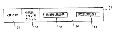
データの特殊な記述を指定するようにタイプフィールド32を使用する別の例が図8に示されている。図8は、小規模のトランザクションに対する流れ記述子28を示している。小規模のトランザクションとは、データベースのデータに対する変更を行う場合に、影響を受ける全てのデータの変更に関連したオーバーヘッドを被ることを保証するに充分な数の他の変更が生じるまで、データを直接的に変更しないことを指す。タイプフィールド32は、記述フィールド34が小規模なトランザクションに対するデータを保持することを指定する。記述フィールド34は、第1の流れ記述子52と、第2の流れ記述子54を保持する。第1の流れ記述子52は、データの元の流れを記述する。第2の流れ記述子54は、元の流れに対して行われた変更を指定する流れを記述する。データの元の流れは、第2の流れに保持された変更を実施することによって更新される。
【0021】
図9は、複製データを保持する流れに対する流れ記述子28の例を示す。データのロスが破壊的な結果を招かないように、データをしばしば複製しなければならない。特に、システムが多数のコピーをディスクに維持するところの、選択されたデータ構造体がある。このような場合に、データ構造体は、ディスク上の2つの異なる位置にコピーされる。流れ記述子28は、第1の流れ記述子56と、第2の流れ記述子58をその記述フィールド34に含んでいる。第1の流れ記述子56は、第1のデータコピーを保持する第1の流れを記述し、そして第2の流れ記述子58は、別のデータコピーを保持する第2の流れを記述する。タイプフィールド32は、流れが複製データを含むことを指定する値を保持する。
【0022】
本発明の好ましい実施例では、流れに関する情報が図10に示すようなフィールド記述子60に記憶される。このフィールド記述子60は、流れIDを保持する流れIDフィールド62を含んでいる。この流れIDは、オノード(以下で詳細に述べる)内の流れを独特に識別する4バイト長さの識別番号である。更に、フィールド記述子60は、フラグビットを保持するフラグフィールド64を備えている。フィールド記述子60の最終フィールドは、流れに対する流れ記述子28である。
【0023】
流れは、関連ファンクションに基づいて「オノード」にグループ分けされる。オノードはオブジェクトの論理表示に対応し、典型的に、ファイル、ディレクトリー又はサブディレクトリーを構成する全ての流れを保持する。各オノードは、これに含まれる流れの可変サイズの集合体を記述するに必要な情報を含む。
【0024】
図11は、オノード66のフォーマットを示す図である。各オノード66は、関連ファンクションの流れを保持している。各オノード66は、次のフィールドを含む。即ち、長さフィールド68と、ワークIDフィールド70と、フラグフィールド72と、クラスIDフィールド73と、フィールド記述子60(図10に示すような)のアレーを保持するフィールド76とである。長さフィールド68は、オノードの長さを指定する値を保持し、一方、ワークIDフィールド70は、以下で詳細に述べるように、ワークIDマッピングアレー104(図14)へのインデックスを保持する。ワークIDは長さが4バイトである。フラグフィールド72(図11)はフラグビットを保持し、そしてクラスIDフィールド73は、オノードに対するクラスIDを保持する。フィールド76は、フィールド記述子60のパックアレーを保持し、これは、オノード66と共に保持される流れの各々に対するフィールド記述子60を含む。フィールド76のフィールド記述子のアレーに含まれる流れの数は、変化し得る。更に、フィールド76のフィールド記述子のアレーにおける各流れの長さも、変化し得る。従って、オノード66は可変サイズ構造である。オノード66の可変サイズ特性は、ディスク記憶装置16のディスクにおける割り当て単位での内部分割を最小にするよう助成する。
【0025】
オノード66に関するあるデータは、オノードに直接組み込まれない。そうではなくて、このデータは、図12に示すように個別の流れに記憶される。流れ78は、関連オノード66(図11)に関する多数の異なる形式の状態情報を保持する。この状態情報は、フィールド86に保持されたタイムスタンプであって、オノード66が形成された時間を指定するタイムスタンプを含んでいる。フィールド88は、オノード66が変更された最後の時間を指定するタイムスタンプを保持する。同様に、フィールド90は、オノード66がアクセスされた最後の時間を指定するタイムスタンプを保持する。フィールド92は、オノード66のサイズを指定する値を保持し、そしてフィールド94は、オノードのオーナーに対する機密記述子を保持する。流れ78に保持された全ての情報は、関連オノード66に保持されたファイルデータを管理するのに有用である。
【0026】
図12には、状態情報の第2の流れ80も示されている。この流れ80は、3つのフィールド96、98及び100を備えている。各オノード66は、データ処理システム10のグローバルネームスペースに見ることができ、そしてこのグローバルネームスペースは、ルートオノード以外の各オノードが親ノードを有する論理ツリー構造である。フィールド96は、親オノードのワークIDを保持する。フィールド98は、オノード66のための全般的に独特のID(UUID)を保持する。更に、フィールド100は、オノード66のクラスを指定するクラスIDを保持する。各オノード66には独特のクラスが組み合わされる。特に、各オノード66は、特定のクラスのオブジェクトの例である。
【0027】
状態情報の2つの付加的な流れ82及び84も記憶される。流れ82は、親に対するオノード66のネームを保持し、そして流れ84は、オノードのためのアクセス制御リスト(機密で使用される)を保持する。
【0028】
流れ78、80、82及び84は、少なくとも次の2つの理由で別々に記憶される。第1に、この情報を別々に記憶すると、オノード66の平均サイズが減少される。流れ78、80、82及び84は、各オノードごとに記憶されない。その結果、オノードの平均サイズが減少する。第2に、この情報を別々に記憶すると、各オノード66からコードを検索するのに複雑なコードを必要とすることなく、情報の関連グループにプログラムアクセスすることができる。
【0029】
オノード66(図11)は、オノードバケットアレー102(図13)に記憶される。このオノードバケットアレー102は、固定サイズバケットのアレーで構成された可変サイズデータ構造である。バケットのサイズ(例えば、4K)はデータ処理システム10のアーキテクチャに基づくものであるが、システム10のページサイズに一致してもよい。これらバケットは、図13の例では1ないしNと番号付けされている。アレー102の各バケットは、オノード66のパックされた組を含んでいる。図13の例では、バケット2は、単一のオノードのみを含み、一方、バケット1は、2つのオノードを含み、そしてバケット3は、3つのオノードを含むことが明らかである。
【0030】
オノードバケットアレー102は、ファイルデータが移動、削除又は挿入されたときにシャフルされねばならないデータの量を最小にするために使用される。ディスクスペースのブロックを割り当て及び割り当て解除する粒度は固定とされる。換言すれば、メモリブロックは、固定サイズのバケットで、割り当て及び割り当て解除される。そうではなくて、ファイルデータを記憶するために可変サイズの構造が使用された場合には、割り当ての粒度は固定されず、割り当ての粒度を非常に大きくすることができる。
【0031】
効率化のために、オペレーティングシステム24(図1)は、関連オノード66(図11)をアレー102(図14)の同じバケットに記憶するか、又はディスク記憶装置16のディスク上で互いに接近したバケットに記憶する。この記憶戦術は、ディスク上でオノード66を探すシーク時間を、最小にする。一般に、通常一緒にアクセスされるファイルは同じバケットに配置される。一緒にアクセスされるファイルは、例えば、共通のサブディレクトリー又はディレクトリーにあるファイルである。
【0032】
オノードバケットアレー102(図13)は、流れとしてアクセスされる。システム10は、通常、多数のオノードバケットアレー102を記憶し、従って、オノードバケットアレーを保持する多数の流れを記憶する。内部では、オノード間の全ての参照は、ワークIDに基づいている。アレー102のバケット内でオノード66(図11)を位置決めするには、そのオノードに対するワークIDを探すことが必要である。ワークIDのマッピングアレー104(図14)は、ワークIDからオノードバケットアレー102のバケット番号へマップする。次いで、番号付けされたバケットが、オノードに対し整合ワークIDでサーチされる。特に、特定ノード66のワークIDは、ワークIDマッピングアレー104へインデックスを与える。指定されたインデックスにおけるエントリーは、オノード66を保持するバケット番号を識別する。例えば、図14に示すように、ワークIDマッピングアレー104のエントリー106及び108は、関連するワークIDを有するオノード66がバケット1に保持されることを指定する値を保持する。
【0033】
各オノード66(図11)は、フィールド記述子76のアレーに保持される流れの中に記憶されるネームインデックスの流れを含んでいる。ネームインデックスの流れは、オノード66内に含まれた流れ記述子に対するBツリーインデックスを保持する。ネームインデックスの流れは、流れの流れIDを、オノード66内に保持された流れ記述子を位置決めするためのキーとして使用する。Bツリーインデックスは、本発明と同日に出願された共通の譲受人に譲渡された「ファイルシステムにオブジェクトを効率的に記憶する方法(Efficient Storage of Objects in a File System) 」と題する特許出願に詳細に示されている。この特許出願の開示を参考としてここに取り上げる。
【0034】
流れの関連収集体が、オノード66(図11)へと収集されるのと同様に、オノードの関連収集体がオブジェクト記憶カタログとして知られたデータ構造へ収集される。オノード66のワークIDは、オブジェクト記憶カタログ内のオノードを識別するためのベースとして働く。オブジェクト記憶カタログは、図15に示すようなオブジェクト記憶カタログオノード110によって記述される。オブジェクト記憶カタログオノード110は、長さフィールド68と、ワークIDフィールド70と、フラグフィールド72と、他のオノード66で見つかったフィールド記述子76のアレーとを含んでいる。フィールド記述子76のアレーは、流れ記述子112、114及び116が記憶されたフィールド記述子を含む。
【0035】
流れ記述子112は、ワークIDマッピングアレーの流れ104を記述する。流れ記述子114は、オノードバケットアレーの流れ102を記述し、そして流れ記述子116は、ネームインデックスの流れ117を記述する。ワークIDマッピングアレーの流れ104及びオノードバケットアレーの流れ102は、関連データを記憶するので、これらは共通のオノード(即ち、オブジェクト記憶カタログオノード110)に記憶される。このように、オブジェクト記憶カタログオノード110は、ワークIDマッピングアレーの流れ104、オノードバケットアレーの流れ102及びネームインデックスの流れ117を関係付けるビークルを形成する。オブジェクト記憶カタログオノード110は、ワークID 0におけるカタログを構成するオノードのグループ内に記憶される。ワークID 0とは、その定義により、オノードバケットアレーの流れ102の第1エレメントに常に配置される。ワークID 0における第1バケットは、既知の位置を有する区別されたバケットである。従って、バケット内に記憶されたデータ構造は容易に且つ簡単にアクセスされる。
【0036】
本発明を好ましい実施例について説明したが、特許請求の範囲に規定された本発明の範囲から逸脱せずにその形態及び細部に種々の変更がなされ得ることが当業者に明らかであろう。
【図面の簡単な説明】
【図1】 本発明の好ましい実施例によるデータ処理システムのブロック図である。
【図2】 本発明の好ましい実施例に用いられる流れ記述子のフォーマットを示す図である。
【図3】 本発明の好ましい実施例による極小の流れに対する流れ記述子の図である。
【図4】 本発明の好ましい実施例による小さな流れに対する流れ記述子の図である。
【図5】 本発明の好ましい実施例による大きな流れに対する流れ記述子の図である。
【図6】 本発明の好ましい実施例による圧縮流に対する流れ記述子の図である。
【図7】 本発明の好ましい実施例による暗号流に対する流れ記述子の図である。
【図8】 本発明の好ましい実施例による小規模トランザクションに対する流れ記述子の図である。
【図9】 本発明の好ましい実施例による複製データに対する流れ記述子の図である。
【図10】 本発明の好ましい実施例によるフィールド記述子の図である。
【図11】 本発明の好ましい実施例によるオノードの図である。
【図12】 図11のオノードについての適切な情報を保持するシステムの図である。
【図13】 本発明の好ましい実施例によるバケットアレーの図である。
【図14】 本発明の好ましい実施例によるワークIDマッピングアレー及びオノードバケットアレーの図である。
【図15】 本発明の好ましい実施例によるオブジェクト記憶カタログの図である。
【符号の説明】
10 データ処理システム
12 中央処理ユニット
14 メモリ
16 ディスク記憶装置
18 キーボード
20 マウス
22 ビデオディスプレイ
24 オペレーティングシステム
26 ファイルシステム
28 流れ記述子
30 サイズフィールド
32 タイプフィールド
34 記述フィールド
38、40 サブフィールド
42 イクステント
43 第2の流れ記述子
60 フィールド記述子
66 オノード
68 長さフィールド
70 ワークIDフィールド
72 フラグフィールド
73 クラスIDフィールド
76 フィールド
78 流れ
80 第2の流れ[0001]
[Industrial application fields]
The present invention generally relates to data processing systems, and more particularly to a method for storing data on a disk by a file system.
[0002]
[Prior art]
The conventional file system has a problem in that file data is efficiently stored on a disk. Many conventional systems employ a method of storing all data on a disk in a single size storage unit. Unfortunately, this approach does not efficiently store file data on disk. In particular, the file data varies in size and therefore does not match well with a predetermined storage unit size. Other conventional systems give the user the option of adopting one of many different formats. Before the file data can be used by the user, it must be determined which format is to be adopted. As a result, the user's choice of format is merely a guess and often does not correspond well with actual file data. Therefore, file data is often not stored efficiently.
[0003]
[Problems to be solved by the invention]
In a conventional operating system, a fixed number of disk space blocks are allocated to each file, and file data and control information about the file are stored. These blocks are fixed in size so that units can be quickly assigned and deallocated. Control information for files and file data is often variable sized, which poses at least two problems. First, when file data and / or control information is not large enough to fill a block, disk space within the allocation unit is wasted. Second, when file data and / or control information is too large to store in one block, it must be stored in multiple blocks, and multiple multiples to specify where the data is stored The pointer must be maintained. Maintaining and using such pointers is often quite cumbersome.
[0004]
In the conventional file system, data and metadata (that is, data describing storage of other data) are processed as individual entries. In particular, data and metadata are stored in different formats in the conventional file system. In addition, separate tools are provided that operate on data and metadata. As a result of this separation of data and metadata, overhead and complexity have increased.
[0005]
[Means for Solving the Problems]
The invention of claim 1 is characterized in that the following steps are executed in a data processing apparatus having a file system and a disk storage device.
(A) A flow descriptor of a flow data structure provided by the file system in the disk storage device (16). ( 28 ) Storing therein a data flow (any of 34, 36, 52 and 56) of a variable size flow data structure and a value (32) indicating the type of the data flow, wherein the flow is logical With adjacent bytes of data,
(B) storing a flow descriptor (28), a flow ID (62) and a flag bit (64) for each of the flow data structures in a field descriptor (60) in the disk storage device (16);
(C) In the disk storage device (16), a value (68) indicating the length of the onode, a work ID (70) indicating an index to the work ID mapping array (104), a flag bit (72), an onode (66) Storing an array (76) having a class ID (73) and a variable-size field descriptor in the onode (66) of each variable-size data structure provided by the file system;
(D) In the disk storage device (16), the onode (66) of the variable size data structure is stored in an onode bucket array (102) of fixed size buckets of disk space provided by the file system. Step,
(E) A mapping structure provided by the file system, the work ID mapping array having a mapping structure that holds entries (106, 108) that specify bucket identifiers for buckets in the onode bucket array (102) Storing (104) in the disk storage device (16);
(F) In the disk storage device (16), using the work ID mapping array (104) of the mapping structure, an onode (of variable size data structure in the onode bucket array (102) to which the identifier is given ( 66) showing one position (bucket number).
[0006]
The invention of claim 2 is the method of claim 1, wherein in the disk storage device (16), the onode bucket array (102) is one of the onodes (66) of the plurality of flow data structures. (110).
[0007]
According to a third aspect of the present invention, in the method of the second aspect, in the disk storage device (16), the work ID mapping array (104) of the mapping structure is one of the onodes (66) of the plurality of flow data structures. (110).
[0008]
The invention according to claim 4 is the method according to
A fifth aspect of the present invention is the method according to the third aspect, wherein in the disk storage device (16), the onode (66) of the selected variable size data structure is a plurality of the onode bucket array (102). Stored in one of the buckets.
[0009]
【Example】
The preferred embodiment of the present invention provides a file system that stores both data and metadata as "flow" groups on disk. A “flow” is a variable-size array of data bytes that are logically contiguous and can be accessed randomly, and that acts as a logical storage unit on the disk. Most program access to the file data is done by these flows. Each stream is stored on disk for one of many different representations. Each of the different displays is well suited for a specific size and use of the flow. Thus, each stream is stored on disk for a display format that best suits its size.
[0010]
Each flow is combined with a flow descriptor, which is stored in the control structure in the file system. The flow descriptor is used to access the flow and obtain information about the flow. The flow descriptor provides a description for storing and displaying flow data. The data flow that holds the relevant data is encapsulated into a data structure known as an onode. An onode is a variable-sized structure that is almost similar to a file, directory, or subdirectory. The group of related onodes is then stored in a data structure known as an object store catalog or object store. Thus, data and metadata (such as object storage catalogs) are hierarchically described in a similar manner, which will be described in detail below.
[0011]
FIG. 1 is a block diagram of a
[0012]
The memory 14 maintains a copy of the
[0013]
As noted above, in the preferred embodiment of the present invention, the flow is obtained during a number of different displays. In order to understand the different representations of a flow, it will be useful to consider the format of the flow descriptor given to the flow. FIG. 2 is a diagram showing the format of the
[0014]
“Minimum flow” is a first example of a flow that can be used in a preferred embodiment of the present invention. This minimal flow is used to store data that is very small in size relative to the allocation unit of the storage medium (ie, the disk of the disk storage device 16). The “allocation unit” of the storage medium refers to the basic unit of the disk memory space of the
[0015]
Another example that can be used in the preferred embodiment of the present invention is a small stream. A “small stream” is a stream that is stored with a single extent of data. An extent is a variable size adjacent extension of an allocation unit. The flow data is stored in extent because it is too large to store directly in the flow descriptor. The format of the
[0016]
A third example that can be used in the preferred embodiment of the present invention is "big flow". This large flow is a flow that is stored in multiple extents. This large stream is suitable for storing streams with a large amount of data. FIG. 5 shows the format of the
[0017]
As the flow size grows, the flow display is prompted to climb the flow display hierarchy to facilitate efficient storage of the flow. Hierarchies include minimal flow, small flow and large flow. Flow is promoted from minimal flow to small flow and from large flow. In general, as described above, a display form most suitable for a flow is selected based on the amount of data included in the flow and the amount of subdivision.
[0018]
The four basic flow formats that can be used in the preferred embodiment of the present invention have been described above. The
[0019]
FIG. 7 shows the format of the
[0020]
Another example of using the
[0021]
FIG. 9 shows an example of a
[0022]
In the preferred embodiment of the present invention, information about the flow is stored in a
[0023]
The flows are grouped into “onodes” based on related functions. An onode corresponds to a logical representation of an object and typically holds all the streams that make up a file, directory or subdirectory. Each onode contains the information necessary to describe a variable-size collection of flows contained therein.
[0024]
FIG. 11 is a diagram showing the format of the
[0025]
Some data regarding the
[0026]
Also shown in FIG. 12 is a
[0027]
Two
[0028]
[0029]
The onode 66 (FIG. 11) is stored in the onode bucket array 102 (FIG. 13). The
[0030]
The
[0031]
For efficiency, the operating system 24 (FIG. 1) stores the associated onodes 66 (FIG. 11) in the same bucket of the array 102 (FIG. 14) or buckets that are close together on the disk of the
[0032]
The onode bucket array 102 (FIG. 13) is accessed as a flow.
[0033]
Each onode 66 (FIG. 11) includes a name index stream that is stored in a stream maintained in an array of
[0034]
Just as the flow related collection is collected into the onode 66 (FIG. 11), the onode related collection is collected into a data structure known as an object storage catalog. The work ID of the
[0035]
The
[0036]
While the invention has been described in terms of a preferred embodiment, it will be apparent to those skilled in the art that various changes in form and detail can be made without departing from the scope of the invention as defined in the claims.
[Brief description of the drawings]
FIG. 1 is a block diagram of a data processing system according to a preferred embodiment of the present invention.
FIG. 2 is a diagram illustrating a format of a flow descriptor used in a preferred embodiment of the present invention.
FIG. 3 is a flow descriptor diagram for a minimal flow according to a preferred embodiment of the present invention.
FIG. 4 is a flow descriptor diagram for a small flow according to a preferred embodiment of the present invention.
FIG. 5 is a flow descriptor diagram for a large flow according to a preferred embodiment of the present invention.
FIG. 6 is a flow descriptor diagram for a compressed flow according to a preferred embodiment of the present invention.
FIG. 7 is a flow descriptor diagram for a cryptographic stream according to a preferred embodiment of the present invention.
FIG. 8 is a flow descriptor diagram for a small transaction according to a preferred embodiment of the present invention.
FIG. 9 is a flow descriptor diagram for replicated data according to a preferred embodiment of the present invention.
FIG. 10 is a diagram of a field descriptor according to a preferred embodiment of the present invention.
FIG. 11 is a diagram of an onode according to a preferred embodiment of the present invention.
FIG. 12 is a diagram of a system that retains appropriate information about the onode of FIG.
FIG. 13 is a diagram of a bucket array according to a preferred embodiment of the present invention.
FIG. 14 is a diagram of a work ID mapping array and an onode bucket array according to a preferred embodiment of the present invention.
FIG. 15 is a diagram of an object storage catalog according to a preferred embodiment of the present invention.
[Explanation of symbols]
10 Data processing system
12 Central processing unit
14 memory
16 disk storage
18 Keyboard
20 mice
22 Video display
24 Operating system
26 File system
28 Flow descriptor
30 size field
32 Type field
34 Description field
38, 40 subfield
42 extent
43 Second flow descriptor
60 field descriptors
66 Onode
68 Length field
70 Work ID field
72 Flag field
73 Class ID field
76 fields
78 Flow
80 Second flow
Claims (5)
(a)前記ディスク記憶装置(16)において、前記ファイルシステムにより提供される流れデータ構造の流れ記述子 ( 28 )中に、可変サイズの流れデータ構造のデータの流れ(34、36、52および56のいずれか)および該データの流れのタイプを示す値(32)を格納するステップ、ここで、前記流れは論理的に隣接するデータのバイトを有し、
(b)前記ディスク記憶装置(16)において、各前記流れデータ構造についての流れ記述子(28)、流れID(62)およびフラグビット(64)をフィールド記述子(60)に記憶するステップ、
(c)前記ディスク記憶装置(16)において、オノードの長さを示す値(68)、ワークIDマッピングアレイ(104)へのインデックスを示すワークID(70)およびフラグビット(72)、オノード(66)に対するクラスID(73)および可変サイズの前記フィールド記述子を有するアレイ(76)を、前記ファイルシステムにより提供される、それぞれの可変サイズのデータ構造のオノード(66)中に格納するステップ、
(d)前記ディスク記憶装置(16)において、前記ファイルシステムにより提供されるディスクスペースの固定サイズのバケットのオノードバケットアレイ(102)中に前記可変サイズのデータ構造のオノード(66)を格納するステップ、
(e)前記ファイルシステムにより提供されるマッピング構造であって、前記オノードバケットアレイ(102)中のバケットについてのバケット識別子を指定するエントリ(106、108)を保持するマッピング構造のワークIDマッピングアレイ(104)を、前記ディスク記憶装置(16)において記憶するステップ、
(f)前記ディスク記憶装置(16)において、前記マッピング構造のワークIDマッピングアレイ(104)を使用して、前記識別子が与えられるオノードバケットアレイ(102)中の可変サイズのデータ構造のオノード(66)の1つの位置(バケット番号)を示すステップ。In a data processing apparatus having a file system and a disk storage device, the following steps are executed.
(A) In the disk storage device (16) , in the flow data structure flow descriptor ( 28 ) provided by the file system , the data flow (34, 36, 52 and 56 of variable size flow data structure ). any) and storing the value (32) indicating the type of flow of said data, wherein said stream have a byte of data to be logically contiguous,
(B) storing a flow descriptor (28), a flow ID (62) and a flag bit (64) for each of the flow data structures in a field descriptor (60) in the disk storage device (16) ;
(C) In the disk storage device (16) , a value (68) indicating the length of the onode, a work ID (70) indicating an index to the work ID mapping array (104), a flag bit (72), an onode (66) Storing an array (76) having a class ID (73) and a variable-size field descriptor in the onode (66) of each variable-size data structure provided by the file system ;
(D) In the disk storage device (16), the onode (66) of the variable size data structure is stored in an onode bucket array (102) of fixed size buckets of disk space provided by the file system. Step ,
(E) A mapping structure provided by the file system , the work ID mapping array having a mapping structure that holds entries (106, 108) that specify bucket identifiers for buckets in the onode bucket array (102) Storing (104) in the disk storage device (16) ;
(F) In the disk storage device (16), using the work ID mapping array (104) of the mapping structure, an onode ( of variable size data structure in the onode bucket array (102) to which the identifier is given ( 66) showing one position (bucket number) .
Applications Claiming Priority (2)
| Application Number | Priority Date | Filing Date | Title |
|---|---|---|---|
| US8548393A | 1993-06-30 | 1993-06-30 | |
| US08/085483 | 1993-06-30 |
Related Child Applications (1)
| Application Number | Title | Priority Date | Filing Date |
|---|---|---|---|
| JP2006345022A Division JP4034331B2 (en) | 1993-06-30 | 2006-12-21 | Method for storing flow data in a disk storage device |
Publications (2)
| Publication Number | Publication Date |
|---|---|
| JPH0756787A JPH0756787A (en) | 1995-03-03 |
| JP3926857B2 true JP3926857B2 (en) | 2007-06-06 |
Family
ID=22191905
Family Applications (2)
| Application Number | Title | Priority Date | Filing Date |
|---|---|---|---|
| JP14192394A Expired - Lifetime JP3926857B2 (en) | 1993-06-30 | 1994-06-23 | Metadata structure and method of handling the same |
| JP2006345022A Expired - Lifetime JP4034331B2 (en) | 1993-06-30 | 2006-12-21 | Method for storing flow data in a disk storage device |
Family Applications After (1)
| Application Number | Title | Priority Date | Filing Date |
|---|---|---|---|
| JP2006345022A Expired - Lifetime JP4034331B2 (en) | 1993-06-30 | 2006-12-21 | Method for storing flow data in a disk storage device |
Country Status (5)
| Country | Link |
|---|---|
| US (1) | US5758360A (en) |
| EP (1) | EP0632367B1 (en) |
| JP (2) | JP3926857B2 (en) |
| CA (1) | CA2124752C (en) |
| DE (1) | DE69431499T2 (en) |
Families Citing this family (30)
| Publication number | Priority date | Publication date | Assignee | Title |
|---|---|---|---|---|
| US6023744A (en) * | 1997-03-07 | 2000-02-08 | Microsoft Corporation | Method and mechanism for freeing disk space in a file system |
| US5895470A (en) * | 1997-04-09 | 1999-04-20 | Xerox Corporation | System for categorizing documents in a linked collection of documents |
| US7331058B1 (en) * | 1999-12-16 | 2008-02-12 | International Business Machines Corporation | Distributed data structures for authorization and access control for computing resources |
| US7177940B1 (en) * | 2000-04-24 | 2007-02-13 | Microsoft Corporation | Representing a service discovery stream as an N-ary tree |
| EP1295293A2 (en) * | 2000-06-09 | 2003-03-26 | Koninklijke Philips Electronics N.V. | Method of implicit partitioning the storage space available on a storage medium |
| JP4273636B2 (en) * | 2000-06-30 | 2009-06-03 | ソニー株式会社 | Information recording apparatus and method, and information recording system |
| US6947947B2 (en) * | 2001-08-17 | 2005-09-20 | Universal Business Matrix Llc | Method for adding metadata to data |
| US6636942B2 (en) | 2001-10-05 | 2003-10-21 | International Business Machines Corporation | Storage structure for storing formatted data on a random access medium |
| US7146564B2 (en) * | 2001-12-21 | 2006-12-05 | Xmlcities, Inc. | Extensible stylesheet designs using meta-tag and/or associated meta-tag information |
| US20050138011A1 (en) * | 2003-12-23 | 2005-06-23 | Royer Robert J.Jr. | Meta-data storage and access techniques |
| US7633886B2 (en) * | 2003-12-31 | 2009-12-15 | University Of Florida Research Foundation, Inc. | System and methods for packet filtering |
| WO2005069783A2 (en) * | 2004-01-09 | 2005-08-04 | T.W. Storage, Inc. | Methods and apparatus for searching backup data based on content and attributes |
| WO2005078606A2 (en) * | 2004-02-11 | 2005-08-25 | Storage Technology Corporation | Clustered hierarchical file services |
| US7917480B2 (en) | 2004-08-13 | 2011-03-29 | Google Inc. | Document compression system and method for use with tokenspace repository |
| US8407239B2 (en) | 2004-08-13 | 2013-03-26 | Google Inc. | Multi-stage query processing system and method for use with tokenspace repository |
| US7068192B1 (en) * | 2004-08-13 | 2006-06-27 | Google Inc. | System and method for encoding and decoding variable-length data |
| WO2006069228A2 (en) * | 2004-12-22 | 2006-06-29 | Musicgiants, Inc. | Unified media collection system |
| US20070203874A1 (en) * | 2006-02-24 | 2007-08-30 | Intervoice Limited Partnership | System and method for managing files on a file server using embedded metadata and a search engine |
| US20080052284A1 (en) * | 2006-08-05 | 2008-02-28 | Terry Stokes | System and Method for the Capture and Archival of Electronic Communications |
| US20080154986A1 (en) * | 2006-12-22 | 2008-06-26 | Storage Technology Corporation | System and Method for Compression of Data Objects in a Data Storage System |
| US8683228B2 (en) * | 2007-01-16 | 2014-03-25 | Terry Lee Stokes | System and method for WORM data storage |
| US8005790B2 (en) * | 2007-02-07 | 2011-08-23 | Agfa Healthcare N.V. | Object cloning management system and method |
| US20100088283A1 (en) * | 2008-10-03 | 2010-04-08 | Microsoft Corporation | System and method for managing database applications |
| US9747300B2 (en) | 2011-06-15 | 2017-08-29 | Amazon Technologies, Inc. | Local networked storage linked to remote networked storage system |
| US9069707B1 (en) * | 2011-11-03 | 2015-06-30 | Permabit Technology Corp. | Indexing deduplicated data |
| US9953042B1 (en) | 2013-03-01 | 2018-04-24 | Red Hat, Inc. | Managing a deduplicated data index |
| US9317213B1 (en) * | 2013-05-10 | 2016-04-19 | Amazon Technologies, Inc. | Efficient storage of variably-sized data objects in a data store |
| US9557937B2 (en) * | 2013-08-21 | 2017-01-31 | Netapp, Inc. | Systems, methods, and computer program products implementing hybrid file structures for data storage |
| US9772787B2 (en) * | 2014-03-31 | 2017-09-26 | Amazon Technologies, Inc. | File storage using variable stripe sizes |
| US20230034727A1 (en) * | 2021-07-29 | 2023-02-02 | Rakuten Group, Inc. | Blur-robust image segmentation |
Family Cites Families (14)
| Publication number | Priority date | Publication date | Assignee | Title |
|---|---|---|---|---|
| US4536837A (en) * | 1982-05-25 | 1985-08-20 | Elxsi | Improved disk file allocation and mapping system utilizing cylinder control blocks and file map having unbalanced tree structure |
| US4775969A (en) * | 1986-05-15 | 1988-10-04 | Aquidneck Systems International, Inc. | Optical disk storage format, method and apparatus for emulating a magnetic tape drive |
| US5119291A (en) * | 1987-03-26 | 1992-06-02 | International Business Machines Corporation | Modular data storage directories for large-capacity data storage units wherein the index to the records in a sector is located in the next adjacent sector |
| JPH01306917A (en) * | 1988-05-20 | 1989-12-11 | Internatl Business Mach Corp <Ibm> | Memory control method and apparatus |
| US5301304A (en) * | 1988-05-20 | 1994-04-05 | International Business Machines Corporation | Emulating records in one record format in another record format |
| US5200864A (en) * | 1989-06-28 | 1993-04-06 | International Business Machines Corporation | Combining small records into a single record block for recording on a record media |
| US5276874A (en) * | 1989-08-11 | 1994-01-04 | Digital Equipment Corporation | Method for creating a directory tree in main memory using an index file in secondary memory |
| JP2746734B2 (en) * | 1990-06-08 | 1998-05-06 | 富士通株式会社 | Access processing method for stream file |
| US5206939A (en) * | 1990-09-24 | 1993-04-27 | Emc Corporation | System and method for disk mapping and data retrieval |
| US5297124A (en) * | 1992-04-24 | 1994-03-22 | Miltope Corporation | Tape drive emulation system for a disk drive |
| US5506983A (en) * | 1992-07-06 | 1996-04-09 | Microsoft Corporation | Method and system for transactioning of modifications to a tree structured file |
| US5394534A (en) * | 1992-09-11 | 1995-02-28 | International Business Machines Corporation | Data compression/decompression and storage of compressed and uncompressed data on a same removable data storage medium |
| US5454103A (en) * | 1993-02-01 | 1995-09-26 | Lsc, Inc. | Method and apparatus for file storage allocation for secondary storage using large and small file blocks |
| US5613105A (en) * | 1993-06-30 | 1997-03-18 | Microsoft Corporation | Efficient storage of objects in a file system |
-
1994
- 1994-05-31 CA CA002124752A patent/CA2124752C/en not_active Expired - Lifetime
- 1994-06-23 JP JP14192394A patent/JP3926857B2/en not_active Expired - Lifetime
- 1994-06-28 DE DE69431499T patent/DE69431499T2/en not_active Expired - Lifetime
- 1994-06-28 EP EP94110018A patent/EP0632367B1/en not_active Expired - Lifetime
-
1996
- 1996-08-02 US US08/693,491 patent/US5758360A/en not_active Expired - Lifetime
-
2006
- 2006-12-21 JP JP2006345022A patent/JP4034331B2/en not_active Expired - Lifetime
Also Published As
| Publication number | Publication date |
|---|---|
| JP2007128543A (en) | 2007-05-24 |
| DE69431499D1 (en) | 2002-11-14 |
| DE69431499T2 (en) | 2003-02-27 |
| CA2124752C (en) | 2005-04-12 |
| US5758360A (en) | 1998-05-26 |
| EP0632367A1 (en) | 1995-01-04 |
| JPH0756787A (en) | 1995-03-03 |
| EP0632367B1 (en) | 2002-10-09 |
| JP4034331B2 (en) | 2008-01-16 |
| CA2124752A1 (en) | 1994-12-31 |
Similar Documents
| Publication | Publication Date | Title |
|---|---|---|
| JP4034331B2 (en) | Method for storing flow data in a disk storage device | |
| JP4395536B2 (en) | How to store file data on disk | |
| JP4250190B2 (en) | Efficient storage of objects in the file system | |
| US5829053A (en) | Block storage memory management system and method utilizing independent partition managers and device drivers | |
| US7162486B2 (en) | System and method for representing named data streams within an on-disk structure of a file system | |
| CN108804510B (en) | Key value file system | |
| EP0733238B1 (en) | Extended attributes file system | |
| US6353837B1 (en) | Method and apparatus providing mass storage access from systems using different meta-data formats | |
| US6029170A (en) | Hybrid tree array data structure and method | |
| US4849878A (en) | Self-extending administrative memory file | |
| WO1996041283A9 (en) | System and method for superimposing attributes on hierarchically organized file systems | |
| WO1996041283A1 (en) | System and method for superimposing attributes on hierarchically organized file systems | |
| US8832081B2 (en) | Structured large object (LOB) data | |
| US5860079A (en) | Arrangement and method for efficient calculation of memory addresses in a block storage memory system | |
| JPH0358249A (en) | Access method of file | |
| US6625614B1 (en) | Implementation for efficient access of extended attribute data | |
| JP2002140220A (en) | File management method and recording medium | |
| JPS595372A (en) | File processing system | |
| JPH06223106A (en) | Document managing device | |
| Sikeler | VAR-PAGE-LRU | |
| JPH03276254A (en) | Document control system | |
| JPH0298752A (en) | Secondary storage area managing system by binary tree |
Legal Events
| Date | Code | Title | Description |
|---|---|---|---|
| A601 | Written request for extension of time |
Free format text: JAPANESE INTERMEDIATE CODE: A601 Effective date: 20040113 |
|
| A602 | Written permission of extension of time |
Free format text: JAPANESE INTERMEDIATE CODE: A602 Effective date: 20040116 |
|
| A521 | Request for written amendment filed |
Free format text: JAPANESE INTERMEDIATE CODE: A523 Effective date: 20040412 |
|
| A02 | Decision of refusal |
Free format text: JAPANESE INTERMEDIATE CODE: A02 Effective date: 20041224 |
|
| RD13 | Notification of appointment of power of sub attorney |
Free format text: JAPANESE INTERMEDIATE CODE: A7433 Effective date: 20050324 |
|
| A521 | Request for written amendment filed |
Free format text: JAPANESE INTERMEDIATE CODE: A821 Effective date: 20050324 |
|
| A521 | Request for written amendment filed |
Free format text: JAPANESE INTERMEDIATE CODE: A523 Effective date: 20050425 |
|
| A911 | Transfer to examiner for re-examination before appeal (zenchi) |
Free format text: JAPANESE INTERMEDIATE CODE: A911 Effective date: 20050525 |
|
| A912 | Re-examination (zenchi) completed and case transferred to appeal board |
Free format text: JAPANESE INTERMEDIATE CODE: A912 Effective date: 20051126 |
|
| RD13 | Notification of appointment of power of sub attorney |
Free format text: JAPANESE INTERMEDIATE CODE: A7433 Effective date: 20060418 |
|
| A521 | Request for written amendment filed |
Free format text: JAPANESE INTERMEDIATE CODE: A821 Effective date: 20060418 |
|
| A521 | Request for written amendment filed |
Free format text: JAPANESE INTERMEDIATE CODE: A523 Effective date: 20061221 |
|
| A61 | First payment of annual fees (during grant procedure) |
Free format text: JAPANESE INTERMEDIATE CODE: A61 Effective date: 20070301 |
|
| R150 | Certificate of patent or registration of utility model |
Free format text: JAPANESE INTERMEDIATE CODE: R150 |
|
| A521 | Request for written amendment filed |
Free format text: JAPANESE INTERMEDIATE CODE: A523 Effective date: 20040412 |
|
| FPAY | Renewal fee payment (event date is renewal date of database) |
Free format text: PAYMENT UNTIL: 20110309 Year of fee payment: 4 |
|
| FPAY | Renewal fee payment (event date is renewal date of database) |
Free format text: PAYMENT UNTIL: 20110309 Year of fee payment: 4 |
|
| FPAY | Renewal fee payment (event date is renewal date of database) |
Free format text: PAYMENT UNTIL: 20120309 Year of fee payment: 5 |
|
| FPAY | Renewal fee payment (event date is renewal date of database) |
Free format text: PAYMENT UNTIL: 20130309 Year of fee payment: 6 |
|
| FPAY | Renewal fee payment (event date is renewal date of database) |
Free format text: PAYMENT UNTIL: 20130309 Year of fee payment: 6 |
|
| FPAY | Renewal fee payment (event date is renewal date of database) |
Free format text: PAYMENT UNTIL: 20140309 Year of fee payment: 7 |
|
| R250 | Receipt of annual fees |
Free format text: JAPANESE INTERMEDIATE CODE: R250 |
|
| EXPY | Cancellation because of completion of term |