JP3924967B2 - Encoding apparatus and method, decoding apparatus and method, recording medium, and data processing system - Google Patents
Encoding apparatus and method, decoding apparatus and method, recording medium, and data processing system Download PDFInfo
- Publication number
- JP3924967B2 JP3924967B2 JP33370098A JP33370098A JP3924967B2 JP 3924967 B2 JP3924967 B2 JP 3924967B2 JP 33370098 A JP33370098 A JP 33370098A JP 33370098 A JP33370098 A JP 33370098A JP 3924967 B2 JP3924967 B2 JP 3924967B2
- Authority
- JP
- Japan
- Prior art keywords
- data
- block
- bit
- image
- bits
- Prior art date
- Legal status (The legal status is an assumption and is not a legal conclusion. Google has not performed a legal analysis and makes no representation as to the accuracy of the status listed.)
- Expired - Fee Related
Links
Images


Classifications
-
- H—ELECTRICITY
- H04—ELECTRIC COMMUNICATION TECHNIQUE
- H04L—TRANSMISSION OF DIGITAL INFORMATION, e.g. TELEGRAPHIC COMMUNICATION
- H04L9/00—Cryptographic mechanisms or cryptographic arrangements for secret or secure communications; Network security protocols
- H04L9/06—Cryptographic mechanisms or cryptographic arrangements for secret or secure communications; Network security protocols the encryption apparatus using shift registers or memories for block-wise or stream coding, e.g. DES systems or RC4; Hash functions; Pseudorandom sequence generators
-
- H—ELECTRICITY
- H04—ELECTRIC COMMUNICATION TECHNIQUE
- H04N—PICTORIAL COMMUNICATION, e.g. TELEVISION
- H04N1/00—Scanning, transmission or reproduction of documents or the like, e.g. facsimile transmission; Details thereof
- H04N1/32—Circuits or arrangements for control or supervision between transmitter and receiver or between image input and image output device, e.g. between a still-image camera and its memory or between a still-image camera and a printer device
- H04N1/32101—Display, printing, storage or transmission of additional information, e.g. ID code, date and time or title
- H04N1/32144—Display, printing, storage or transmission of additional information, e.g. ID code, date and time or title embedded in the image data, i.e. enclosed or integrated in the image, e.g. watermark, super-imposed logo or stamp
- H04N1/32149—Methods relating to embedding, encoding, decoding, detection or retrieval operations
- H04N1/32203—Spatial or amplitude domain methods
- H04N1/32229—Spatial or amplitude domain methods with selective or adaptive application of the additional information, e.g. in selected regions of the image
-
- H—ELECTRICITY
- H04—ELECTRIC COMMUNICATION TECHNIQUE
- H04N—PICTORIAL COMMUNICATION, e.g. TELEVISION
- H04N1/00—Scanning, transmission or reproduction of documents or the like, e.g. facsimile transmission; Details thereof
- H04N1/32—Circuits or arrangements for control or supervision between transmitter and receiver or between image input and image output device, e.g. between a still-image camera and its memory or between a still-image camera and a printer device
- H04N1/32101—Display, printing, storage or transmission of additional information, e.g. ID code, date and time or title
- H04N1/32144—Display, printing, storage or transmission of additional information, e.g. ID code, date and time or title embedded in the image data, i.e. enclosed or integrated in the image, e.g. watermark, super-imposed logo or stamp
- H04N1/32149—Methods relating to embedding, encoding, decoding, detection or retrieval operations
- H04N1/32203—Spatial or amplitude domain methods
- H04N1/32251—Spatial or amplitude domain methods in multilevel data, e.g. greyscale or continuous tone data
-
- H—ELECTRICITY
- H04—ELECTRIC COMMUNICATION TECHNIQUE
- H04N—PICTORIAL COMMUNICATION, e.g. TELEVISION
- H04N1/00—Scanning, transmission or reproduction of documents or the like, e.g. facsimile transmission; Details thereof
- H04N1/32—Circuits or arrangements for control or supervision between transmitter and receiver or between image input and image output device, e.g. between a still-image camera and its memory or between a still-image camera and a printer device
- H04N1/32101—Display, printing, storage or transmission of additional information, e.g. ID code, date and time or title
- H04N1/32144—Display, printing, storage or transmission of additional information, e.g. ID code, date and time or title embedded in the image data, i.e. enclosed or integrated in the image, e.g. watermark, super-imposed logo or stamp
- H04N1/32149—Methods relating to embedding, encoding, decoding, detection or retrieval operations
- H04N1/32267—Methods relating to embedding, encoding, decoding, detection or retrieval operations combined with processing of the image
-
- H—ELECTRICITY
- H04—ELECTRIC COMMUNICATION TECHNIQUE
- H04N—PICTORIAL COMMUNICATION, e.g. TELEVISION
- H04N1/00—Scanning, transmission or reproduction of documents or the like, e.g. facsimile transmission; Details thereof
- H04N1/32—Circuits or arrangements for control or supervision between transmitter and receiver or between image input and image output device, e.g. between a still-image camera and its memory or between a still-image camera and a printer device
- H04N1/32101—Display, printing, storage or transmission of additional information, e.g. ID code, date and time or title
- H04N1/32144—Display, printing, storage or transmission of additional information, e.g. ID code, date and time or title embedded in the image data, i.e. enclosed or integrated in the image, e.g. watermark, super-imposed logo or stamp
- H04N1/32149—Methods relating to embedding, encoding, decoding, detection or retrieval operations
- H04N1/32347—Reversible embedding, i.e. lossless, invertible, erasable, removable or distorsion-free embedding
-
- H—ELECTRICITY
- H04—ELECTRIC COMMUNICATION TECHNIQUE
- H04N—PICTORIAL COMMUNICATION, e.g. TELEVISION
- H04N21/00—Selective content distribution, e.g. interactive television or video on demand [VOD]
- H04N21/20—Servers specifically adapted for the distribution of content, e.g. VOD servers; Operations thereof
- H04N21/23—Processing of content or additional data; Elementary server operations; Server middleware
- H04N21/238—Interfacing the downstream path of the transmission network, e.g. adapting the transmission rate of a video stream to network bandwidth; Processing of multiplex streams
- H04N21/2389—Multiplex stream processing, e.g. multiplex stream encrypting
- H04N21/23892—Multiplex stream processing, e.g. multiplex stream encrypting involving embedding information at multiplex stream level, e.g. embedding a watermark at packet level
Description
【0001】
【発明の属する技術分野】
本発明は、画像処理装置および画像処理方法、提供媒体、並びに画像処理システムに関し、復号画像の画質の劣化を極力なくし、かつデータ量を増加せずに、画像に情報を埋め込むことができるようにする画像処理装置および画像処理方法、提供媒体、並びに画像処理システムに関する。
【0002】
【従来の技術】
ディジタル画像データに対して、そのデータ量を増加させることなく、情報を埋め込む手法としては、例えば、値の大きな画素値の最下位ビットや、下位2ビットなどを、埋め込む情報に置換するものなどがある。この手法は、値の大きな画素値の下位ビットが、画質にあまり影響を与えないことを利用し、その下位ビットを、単に、埋め込む情報に置き換えるものであり、従って、再生時には、情報が埋め込まれた画像データは、その下位ビットを元に戻さずに、そのまま出力される。即ち、このように単に置換することで情報が埋め込まれた下位ビットを、元に戻すのは困難であり、また、値の大きな画素値の下位ビットは、画質に、あまり影響を与えないことから、画像データは、情報が埋め込まれた状態で出力(表示)される。
【0003】
【発明が解決しようとする課題】
しかしながら、以上のような手法では、本来の画像データと異なるデータが出力される。従って、出力される画像の画質に、少なからず影響がある。
【0004】
本発明は、このような状況に鑑みてなされたものであり、画像の画質の劣化を極力なくし、かつデータ量を増加せずに(あるいは、データ量の増加を最低限に抑えて)、画像に情報を埋め込むことができるようにするものである。
【0005】
【課題を解決するための手段】
請求項1に記載の符号化装置は、第1のデータの少なくとも一部のデータを、所定のビット数のデータが複数集められて構成されるブロックにブロック化するブロック化手段と、ブロックを、所定のビット数のデータを表わすビット列の各ビットごとのビットプレーンに分割する分割手段と、第2のデータに従って、第1のデータの少なくとも一部のデータの少なくとも1つのブロックをビットプレーン単位で入れ替えることにより、第1のデータに第2のデータに関するデータを埋め込んで符号化する符号化手段とを備える。
【0006】
請求項8に記載の符号化方法は、第1のデータの少なくとも一部のデータを、所定のビット数のデータが複数集められて構成されるブロックにブロック化するブロック化ステップと、ブロックを、所定のビット数のデータを表わすビット列の各ビットごとのビットプレーンに分割する分割ステップと、第2のデータに従って、第1のデータの少なくとも一部のデータの少なくとも1つのブロックをビットプレーン単位で入れ替えることにより、第1のデータに第2のデータに関するデータを埋め込んで符号化する符号化ステップとを含む。
【0008】
請求項9に記載の復号装置は、符号化データの少なくとも一部のデータを、所定のビット数のデータが複数集められて構成されるブロックにブロック化するブロック手段と、ブロックを、所定のビット数のデータを表わすビット列の各ビットごとのビットプレーンに分割する分割手段と、ブロックの各ビットプレーン内のビットどうしの相関を求める相関演算手段と、相関演算手段により求められた相関に基づいて、符号化データの少なくとも一部のデータの少なくとも1つのブロックをビットプレーン単位で入れ替えることにより符号化データを元の第1のデータに復号すると共に、入れ替えに応じて符号化データに埋め込まれた第2のデータを復号する復号手段とを備える。
【0009】
請求項14に記載の復号方法は、符号化データの少なくとも一部のデータを、所定のビット数のデータが複数集められて構成されるブロックにブロック化するブロック化ステップと、ブロックを、所定のビット数のデータを表わすビット列の各ビットごとのビットプレーンに分割する分割ステップと、ブロックの各ビットプレーン内のビットどうしの相関を求める相関演算ステップと、相関に基づいて、符号化データの少なくとも一部のデータの少なくとも1つのブロックをビットプレーン単位で入れ替えることにより符号化データを元の第1のデータに復号すると共に、入れ替えに応じて符号化データに埋め込まれた第2のデータを復号する復号ステップとを含む。
【0011】
請求項15に記載のデータ処理システムは、第1のデータの少なくとも一部のデータを、所定のビット数のデータが複数集められて構成されるブロックにブロック化する第1のブロック化手段と、ブロックを、所定のビット数のデータを表わすビット列の各ビットごとのビットプレーンに分割する第1の分割手段と、第2のデータに従って、第1のデータの少なくとも一部のデータの少なくとも1つのブロックをビットプレーン単位で入れ替えることにより、第1のデータに第2のデータに関するデータを埋め込んで符号化する符号化手段と、符号化データの少なくとも一部のデータを、所定のビット数のデータが複数集められて構成されるブロックにブロック化する第2のブロック化手段と、ブロックを、所定のビット数のデータを表わすビット列の各ビットごとのビットプレーンに分割する第2の分割手段と、ブロックの各ビットプレーン内のビットどうしの相関を求める相関演算手段と、相関演算手段により求められた相関に基づいて、符号化データの少なくとも一部のデータの少なくとも1つのブロックをビットプレーン単位で入れ替えることにより符号化データを元の第1のデータに復号すると共に、入れ替えに応じて符号化データに埋め込まれた第2のデータを復号する復号手段とを備える。
【0012】
請求項1に記載の符号化装置においては、ブロック化手段は、第1のデータの少なくとも一部のデータを、所定のビット数のデータが複数集められて構成されるブロックにブロック化し、分割手段は、ブロックを、所定のビット数のデータを表わすビット列の各ビットごとのビットプレーンに分割するようになされている。符号化手段は、第2のデータに従って、第1のデータの少なくとも一部のデータの少なくとも1つのブロックをビットプレーン単位で入れ替えることにより、第1のデータに第2のデータに関するデータを埋め込んで符号化するようになされている。
【0013】
請求項8に記載の符号化方法においては、第1のデータの少なくとも一部のデータを、所定のビット数のデータが複数集められて構成されるブロックにブロック化し、ブロックを、所定のビット数のデータを表わすビット列の各ビットごとのビットプレーンに分割し、第2のデータに従って、第1のデータの少なくとも一部のデータの少なくとも1つのブロックをビットプレーン単位で入れ替えることにより、第1のデータに第2のデータに関するデータを埋め込んで符号化するようになされている。
【0015】
請求項9に記載の復号装置においては、ブロック化手段は、符号化データの少なくとも一部のデータを、所定のビット数のデータが複数集められて構成されるブロックにブロック化し、分割手段は、ブロックを、所定のビット数のデータを表わすビット列の各ビットごとのビットプレーンに分割するようになされている。相関演算手段は、ブロックの各ビットプレーン内のビットどうしの相関を求め、復号手段は、相関演算手段により求められた相関に基づいて、符号化データの少なくとも一部のデータの少なくとも1つのブロックをビットプレーン単位で入れ替えることにより符号化データを元の第1のデータに復号すると共に、入れ替えに応じて符号化データに埋め込まれた第2のデータを復号するようになされている。
【0016】
請求項14に記載の復号方法においては、符号化データの少なくとも一部のデータを、所定のビット数のデータが複数集められて構成されるブロックにブロック化し、ブロックを、所定のビット数のデータを表わすビット列の各ビットごとのビットプレーンに分割し、ブロックの各ビットプレーン内のビットどうしの相関を求め、相関に基づいて、符号化データの少なくとも一部のデータの少なくとも1つのブロックをビットプレーン単位で入れ替えることにより符号化データを元の第1のデータに復号すると共に、入れ替えに応じて符号化データに埋め込まれた第2のデータを復号するようになされている。
【0018】
請求項15に記載の画像処理システムにおいては、第1のブロック化手段は、第1のデータの少なくとも一部のデータを、所定のビット数のデータが複数集められて構成されるブロックにブロック化し、第1の分割手段は、ブロックを、所定のビット数のデータを表わすビット列の各ビットごとのビットプレーンに分割するようになされている。符号化手段は、第2のデータに従って、第1のデータの少なくとも一部のデータの少なくとも1つのブロックをビットプレーン単位で入れ替えることにより、第1のデータに第2のデータに関するデータを埋め込んで符号化するようになされている。第2のブロック化手段は、符号化データの少なくとも一部のデータを、所定のビット数のデータが複数集められて構成されるブロックにブロック化し、第2の分割手段は、ブロックを、所定のビット数のデータを表わすビット列の各ビットごとのビットプレーンに分割する第2の分割手段するようになされている。相関演算手段は、ブロックの各ビットプレーン内のビットどうしの相関を求め、復号手段は、相関演算手段により求められた相関に基づいて、符号化データの少なくとも一部のデータの少なくとも1つのブロックをビットプレーン単位で入れ替えることにより符号化データを元の第1のデータに復号すると共に、入れ替えに応じて符号化データに埋め込まれた第2のデータを復号するようになされている。
【0019】
【発明の実施の形態】
以下に、本発明の実施の形態を説明するが、その前に、特許請求の範囲に記載の発明の各手段と以下の実施の形態との対応関係を明らかにするために、各手段の後の括弧内に、対応する実施の形態(但し、一例)を付加して、本発明の特徴を記述すると、次のようになる。
【0020】
即ち、請求項1に記載の符号化装置は、第1のデータを第2のデータに従って符号化する符号化装置であって、第1のデータの少なくとも一部のデータを、所定のビット数のデータが複数集められて構成されるブロックにブロック化するブロック化手段(例えば、図8に示すブロック化部42など)と、ブロックを、所定のビット数のデータを表わすビット列の各ビットごとのビットプレーンに分割する分割手段(例えば、図8に示すビットプレーン化部43など)と、第2のデータに従って、第1のデータの少なくとも一部のデータの少なくとも1つのブロックをビットプレーン単位で入れ替えることにより、第1のデータに第2のデータに関するデータを埋め込んで符号化する符号化手段(例えば、図8に示すビットプレーン交換部44など)とを備える。
【0021】
請求項2に記載の符号化装置は、ブロックの各ビットプレーン内のビットどうしの相関を求める相関演算手段(例えば、図15に示すビットプレーン交換部44など)をさらに備え、符号化手段は、最上位ビットのビットプレーンから最下位ビットのビットプレーンの方向に、相関が昇順に並んでいるブロックのみを、ビットプレーン単位の入れ替えを行う対象とする。
【0022】
請求項4に記載の符号化装置は、ビットプレーン単位の入れ替えの対象としなかったブロックに関するブロック情報を、第2のデータが埋め込まれた第1のデータに付加する付加手段(例えば、図15に示すブロック情報付加部47など)をさらに備える。
【0023】
請求項9に記載の復号装置は、第1のデータが第2のデータにしたがって符号化された符号化データを復号する復号装置であって、符号化データの少なくとも一部のデータを、所定のビット数のデータが複数集められて構成されるブロックにブロック化するブロック手段(例えば、図13に示すブロック化部62など)と、ブロックを、所定のビット数のデータを表わすビット列の各ビットごとのビットプレーンに分割する分割手段(例えば、図13に示すビットプレーン化部63など)と、ブロックの各ビットプレーン内のビットどうしの相関を求める相関演算手段例えば、図13に示すビットプレーン相関計算部65など)と、相関演算手段により求められた相関に基づいて、符号化データの少なくとも一部のデータの少なくとも1つのブロックをビットプレーン単位で入れ替えることにより符号化データを元の第1のデータに復号すると共に、入れ替えに応じて符号化データに埋め込まれた第2のデータを復号する復号手段(例えば、図13に示すビットプレーン並べ替え処理部64および付加情報取得部68など)とを備える。
【0024】
請求項10に記載の復号装置は、ブロックに第2のデータが埋め込まれているか否かを判定する判定手段(例えば、図13に示すビットプレーン並べ替え処理部64など)をさらに備え、復号手段が、判定手段により第2のデータが埋め込まれていると判定されたブロックを、ビットプレーン単位で入れ替える対象のブロックとする。
【0025】
請求項15に記載のデータ処理システムは、第1のデータを第2のデータに従って符号化し、符号化データを復号するデータ処理システムであって、第1のデータの少なくとも一部のデータを、所定のビット数のデータが複数集められて構成されるブロックにブロック化する第1のブロック化手段(例えば、図8に示すブロック化部42など)と、ブロックを、所定のビット数のデータを表わすビット列の各ビットごとのビットプレーンに分割する第1の分割手段(例えば、図8に示すビットプレーン化部43など)と、第2のデータに従って、第1のデータの少なくとも一部のデータの少なくとも1つのブロックをビットプレーン単位で入れ替えることにより、第1のデータに第2のデータに関するデータを埋め込んで符号化する符号化手段(例えば、図8に示すビットプレーン交換部44など)と、符号化データの少なくとも一部のデータを、所定のビット数のデータが複数集められて構成されるブロックにブロック化する第2のブロック化手段(例えば、図13に示すブロック化部62など)と、ブロックを、所定のビット数のデータを表わすビット列の各ビットごとのビットプレーンに分割する第2の分割手段(例えば、図13に示すビットプレーン化部63など)と、ブロックの各ビットプレーン内のビットどうしの相関を求める相関演算手段(例えば、図13に示すビットプレーン相関計算部65など)と、相関演算手段により求められた相関に基づいて、符号化データの少なくとも一部のデータの少なくとも1つのブロックをビットプレーン単位で入れ替えることにより符号化データを元の第1のデータに復号すると共に、入れ替えに応じて符号化データに埋め込まれた第2のデータを復号する復号手段(例えば、図13に示すビットプレーン並べ替え処理部64および付加情報取得部68など)とを備える。
【0026】
なお、勿論この記載は、各手段を上記したものに限定することを意味するものではない。
【0027】
図1は、本発明を適用した画像伝送システム(システムとは、複数の装置が論理的に集合した物をいい、各構成の装置が同一筐体中にあるか否かは問わない)の一実施の形態の構成例を示している。
【0028】
この画像伝送システムは、符号化装置10および復号装置20で構成されており、符号化装置10は、符号化対象としての、例えば、画像を符号化して符号化データを出力し、復号装置20は、その符号化データを、元の画像に復号するようになされている。
【0029】
即ち、画像データベース1は、符号化すべき画像(例えば、ディジタル画像データ)を記憶している。そして、画像データベース1からは、そこに記憶されている画像が読み出され、埋め込み符号化器3に供給される。
【0030】
また、付加情報データベース2は、符号化対象の画像に埋め込むべき情報としての付加情報(例えば、バイナリ形式のディジタルデータ)を記憶している。そして、付加情報データベース2からも、そこに記憶されている付加情報が読み出され、埋め込み符号化器3に供給される。
【0031】
埋め込み符号化器3では、画像データベース1からの画像、および付加情報データベース2からの付加情報が受信される。さらに、埋め込み符号化器3は、画像データベース1からの画像が有するエネルギの偏りを利用して復号を行うことができるように、その画像を、付加情報データベース2からの付加情報にしたがって符号化して出力する。即ち、埋め込み符号化器3は、画像が有するエネルギの偏りを利用して復号を行うことができるように、画像に付加情報を埋め込むことで、その画像を符号化し、符号化データを出力する。埋め込み符号化器3が出力する符号化データは、例えば、光磁気ディスク、磁気ディスク、光ディスク、磁気テープ、相変化ディスクなどでなる記録媒体4に記録され、あるいは、また、例えば、地上波、衛星回線、CATV(Cable Television)網、インターネット、公衆回線などでなる伝送媒体5を介して伝送され、復号装置20に提供される。
【0032】
復号装置20は、埋め込み復号器6で構成され、そこでは、記録媒体4または伝送媒体5を介して提供される符号化データが受信される。さらに、埋め込み復号器6は、その符号化データを、画像が有するエネルギの偏りを利用して、元の画像および付加情報に復号する。復号された画像は、例えば、図示せぬモニタ等に供給されて表示される。また、復号された付加情報は、例えば、所定の処理を行うのに用いられ、あるいはユーザに提示される。
【0033】
次に、図1の埋め込み符号化器3における符号化、および埋め込み復号器6における復号の原理について説明する。
【0034】
一般に、情報と呼ばれるものは、エネルギ(エントロピー)の偏り(普遍性)を有し、この偏りが、情報(価値ある情報)として認識される。即ち、例えば、ある風景を撮影して得られる画像が、そのような風景の画像であると認識されるのは、画像(画像を構成する各画素の画素値など)が、その風景に対応したエネルギの偏りを有するからであり、エネルギの偏りがない画像は、雑音等にすぎず、情報としての利用価値はない。
【0035】
従って、価値ある情報に対して、何らかの操作を施し、その情報が有する本来のエネルギの偏りを、いわば破壊した場合でも、その破壊されたエネルギの偏りを元に戻すことで、何らかの操作が施された情報も、元の情報に戻すことができる。即ち、情報を符号化して得られる符号化データは、その情報が有する本来のエネルギの偏りを利用して、元の情報に復号することができる。
【0036】
ここで、情報が有するエネルギ(の偏り)を表すものとしては、例えば、相関性、連続性、相似性などがある。
【0037】
情報の相関性とは、その情報の構成要素(例えば、画像であれば、その画像を構成する画素やラインなど)どうしの相関(例えば、自己相関や、ある構成要素と他の構成要素との距離など)を意味する。
【0038】
即ち、例えば、いま、図2に示すようなHラインでなる画像があった場合に、その上から1行目のライン(第1ライン)と、他のラインとの相関は、一般に、図3(A)に示すように、第1ラインとの距離が近いライン(図2における画面の上の行のライン)ほど大きくなり、第1ラインとの距離が遠いライン(図2における画面の下の行のライン)ほど小さくなる(第1ラインから近いほど相関が大きくなり、遠いほど相関が小さくなるという相関の偏りがある)。
【0039】
そこで、いま、図2の画像において、第1ラインから近い第Mラインと、第1ラインから遠い第Nラインとを入れ替え(1<M<N≦H)、その入れ替え後の画像について、第1ラインと、他のラインとの相関を計算すると、それは、例えば、図3(B)に示すようになる。
【0040】
即ち、入れ替え後の画像では、第1ラインから近い第Mライン(入れ替え前の第Nライン)との相関が小さくなり、第1ラインから遠い第Nライン(入れ替え前の第Mライン)との相関が大きくなる。
【0041】
従って、図3(B)では、第1ラインから近いほど相関が大きくなり、遠いほど相関が小さくなるという相関の偏りが破壊されている。しかしながら、画像については、一般に、第1ラインから近いほど相関が大きくなり、遠いほど相関が小さくなるという相関の偏りを利用することにより、破壊された相関の偏りを、元に戻すことができる。即ち、図3(B)において、第1ラインから近い第Mラインとの相関が小さく、第1ラインから遠い第Nラインとの相関が大きいのは、画像が有する本来の相関の偏りからすれば、明らかに不自然であり(おかしく)、第Mラインと第Nラインとは入れ替えるべきである。そして、図3(B)における第Mラインと第Nラインとを入れ替えることで、図3(A)に示すような相関、即ち、元の画像を復号することができる。
【0042】
ここで、図2および図3で説明した場合においては、ラインの入れ替えが、画像の符号化を行うこととなる。また、その符号化に際し、埋め込み符号化器3では、例えば、何ライン目を移動するかや、どのラインどうしを入れ替えるかなどが、付加情報にしたがって決定されることになる。一方、埋め込み復号器6では、符号化後の画像、即ち、ラインの入れ替えられた画像を、その相関を利用して、ラインを元の位置に入れ替えることにより、元の画像に戻すことが、画像を復号することとなる。さらに、その復号に際し、埋め込み復号器6において、例えば、何ライン目を移動したかや、どのラインどうしを入れ替えたかなどを検出することが、画像に埋め込まれた付加情報を復号することになる。
【0043】
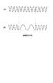
次に、連続性についてであるが、例えば、画像のある1ラインについては、一般に、図4(A)に示すような、周波数の変化が連続している(周波数が滑らかに変化する)信号波形が観察される。即ち、1ラインの周波数に注目すると、一般に、その変化の仕方は連続している。
【0044】
そこで、いま、図4(A)に示した周波数の変化が連続している信号波形の一部を、例えば、図4(B)に示すように、周波数が極端に低いものに入れ替える。
【0045】
この場合、周波数の変化が連続しているという連続性が破壊される。しかしながら、信号波形については、一般に、周波数の変化が連続しているという連続性を利用することにより、破壊された連続性を元に戻すことができる。即ち、図4(B)において、信号波形の一部の周波数が、他の部分の周波数に比較して急激に低くなっているのは、信号波形が有する本来の連続性からすれば、明らかに不自然であり、周波数の極端に低い部分は、他の部分の周波数と同様の周波数の信号波形に入れ替えるべきである。そして、そのような入れ替えを行うことで、図4(B)に示した信号波形から、図4(A)に示した信号波形、即ち、元の信号波形を復号することができる。
【0046】
ここで、図4で説明した場合においては、信号波形の一部について、周波数を大きく変化させること(周波数の大きく異なるものに入れ替えること)が、画像の符号化を行うこととなる。また、その符号化に際し、埋め込み符号化器3では、例えば、信号波形のどの部分の周波数を大きく変化させるのかや、周波数をどの程度大きく変化させるのかなどが、付加情報にしたがって決定されることになる。一方、埋め込み復号器6では、符号化後の信号、即ち、大きく異なる周波数を一部に有する信号波形を、その連続性を利用して、元の信号波形に戻すことが、その元の信号波形を復号することとなる。さらに、その復号に際し、埋め込み復号器6において、例えば、信号波形のどの部分の周波数が大きく変化していたのかや、周波数がどの程度大きく変化していたのかなどを検出することが、埋め込まれた付加情報を復号することになる。
【0047】
次に、相似性についてであるが、例えば、風景を撮影した画像などについては、その拡大画像を、フラクタル(自己相似性)を利用して生成することができることが知られている。即ち、例えば、図5(A)に示すような、海を撮影した画像を、フラクタルを利用して拡大すると、元の画像と同様の特性を有する画像(拡大画像)を得ることができ、従って、風景等を撮影した画像は、相似性を有する。
【0048】
そこで、いま、図5(A)に示した海を撮影した画像の一部を、例えば、図5(B)に示すように、森を撮影した画像の一部(図5(B)において、斜線を付してある部分)に入れ替える。
【0049】
この場合、図5(B)において、森を撮影した画像に入れ替えられた部分については、海を撮影した画像の相似性が破壊される。しかしながら、海を撮影した画像については、一般に、その、どの部分を拡大しても、海を撮影した画像と同様の特性を有する画像が得られるという相似性を利用することにより、破壊された相似性を元に戻すことができる。即ち、図5(B)において、海を撮影した画像の一部が、森を撮影した画像になっているのは、海を撮影した画像が有する本来の相似性からすれば、明らかに不自然であり、森を撮影した画像になっている部分は、その周辺の海の画像と同様の特性を有する画像に入れ替えるべきである。そして、そのような入れ替えを行うことで、図5(B)に示した画像から、図5(A)に示した海のみの画像、即ち、元の画像を復号することができる。
【0050】
ここで、図5で説明した場合においては、海の画像の一部を、森の画像に入れ替えることが、画像の符号化を行うこととなる。また、その符号化に際し、埋め込み符号化器3では、例えば、海の画像のどの部分(画面上の位置)を、森の画像に入れ替えるのかなどが、付加情報にしたがって決定されることになる。一方、埋め込み復号器6では、符号化後の信号、即ち、一部に森の画像を有する海の画像を、その相似性を利用して、元の海のみの画像に戻すことが、その元の画像を復号することとなる。さらに、その復号に際し、埋め込み復号器6において、例えば、海の画像のどの部分が、森の画像に入れ替えられていたのかなどを検出することが、埋め込まれた付加情報を復号することになる。
【0051】
以上のように、埋め込み符号化器3において、符号化対象の画像が有するエネルギの偏りを利用して復号を行うことができるように、その画像を、付加情報にしたがって符号化して、符号化データを出力する場合には、埋め込み復号器6では、その符号化データを、画像が有するエネルギの偏りを利用することにより、復号のためのオーバヘッドなしで、元の画像および付加情報に復号することができる。
【0052】
また、符号化対象の画像には、付加情報が埋め込まれることで、その画像は、元の状態と異なる状態とされることから、符号化対象の画像については、オーバヘッドなしの暗号化を実現することができる。
【0053】
さらに、完全可逆の電子透かしを実現することができる。即ち、従来の電子透かしでは、例えば、画質にあまり影響のない画素値の下位ビットが、電子透かしに対応する値に、単に変更されていたが、この場合、その下位ビットを、元の値に戻すことは困難である。従って、復号画像の画質は、電子透かしとしての下位ビットの変更により、少なからず劣化する。これに対して、符号化データを、元の画像が有するエネルギの偏りを利用して復号する場合には、元の画像および付加情報を得ることができ、従って、付加情報を電子透かしとして用いることで、電子透かしに起因して復号画像の画質が劣化することはない。
【0054】
また、埋め込まれた付加情報は、符号化データから画像を復号することで取り出すことができるので、画像の符号化結果とともに、オーバヘッドなしでサイドインフォメーションを提供することができる。言い換えれば、付加情報を取り出すためのオーバヘッドなしで、その付加情報を画像に埋め込むことができるので、その埋め込みの結果得られる符号化データは、付加情報の分だけ圧縮(埋め込み圧縮)されているということができる。従って、例えば、ある画像の半分を符号化対象とするとともに、残りの半分を付加情報とすれば、符号化対象である半分の画像に、残りの半分の画像を埋め込むことができるから、この場合、画像は、1/2に圧縮されることになる。
【0055】
さらに、符号化データは、元の画像が有するエネルギの偏りという、いわば統計量を利用して復号されるため、誤りに対する耐性の強いものとなる。即ち、ロバスト性の高い符号化であるロバスト符号化(統計的符号化)を実現することができる。
【0056】
また、符号化データは、元の画像が有するエネルギの偏りを利用して復号されるため、そのエネルギの偏りに特徴があるほど、即ち、例えば、画像については、そのアクティビティが高いほど、あるいは、冗長性が低いほど、多くの付加情報を埋め込むことができる。ここで、上述したように、付加情報の埋め込みの結果得られる符号化データは、付加情報の分だけ圧縮されているということができるが、この圧縮という観点からすれば、符号化対象の情報が有するエネルギの偏りを利用して復号を行うことができるように、その情報を、付加情報にしたがって符号化する方式(埋め込み符号化方式)によれば、画像のアクティビティが高いほど、あるいは、画像の冗長性が低いほど、圧縮率が高くなる。この点、埋め込み符号化方式は、従来の符号化方式と大きく異なる(従来の符号化方式である、例えば、MPEG(Moving Picture Experts Group)方式などでは、画像のアクティビティが高いほど、あるいは、画像の冗長性が低いほど、圧縮率は低くなる)。
【0057】
さらに、例えば、上述したように、画像を符号化対象とする一方、付加情報として、画像とは異なるメディアの、例えば、音声を用いるようにすることで、音声をキーとして、画像の提供を行うようなことが可能となる。即ち、符号化装置10側において、例えば、契約者が発話した音声「開けゴマ」など付加情報として画像に埋め込んでおき、復号装置20側では、ユーザに、音声「開けゴマ」を発話してもらい、その音声と、画像に埋め込まれた音声とを用いて話者認識を行うようにする。そして、話者認識の結果、ユーザが契約者である場合にのみ、自動的に、画像を提示するようなことが可能となる。なお、この場合、付加情報としての音声は、いわゆる特徴パラメータではなく、音声波形そのものを用いることが可能である。
【0058】
また、例えば、音声を符号化対象とする一方、付加情報として、音声とは異なるメディアの、例えば、画像を用いるようにすることで、画像をキーとして、音声の提供を行うようなこと(例えば、顔認識音声応答)が可能となる。即ち、符号化装置10側において、例えば、ユーザへの応答としての音声に、そのユーザの顔の画像を埋め込み、復号装置20側では、ユーザの顔を撮影し、その結果得られる画像とマッチングする顔画像が埋め込まれている音声を出力するようにすることで、ユーザごとに異なる音声応答を行う音声応答システムを実現することが可能となる。
【0059】
さらに、音声に、音声を埋め込んだり、画像に、画像を埋め込んだりするような、あるメディアの情報に、それと同一メディアの情報を埋め込むようなことも可能である。あるいは、また、画像に、契約者の音声と顔画像を埋め込んでおけば、ユーザの音声と顔画像とが、画像に埋め込まれているものと一致するときのみ、その画像を提示するようにする、いわば二重鍵システムなどの実現も可能となる。
【0060】
また、例えば、テレビジョン放送信号を構成する、いわば同期した画像と音声のうちのいずれか一方に、他方を埋め込むようなことも可能であり、この場合、異なるメディアの情報どうしを統合した、いわば統合符号化を実現することができる。
【0061】
さらに、埋め込み符号化方式では、上述したように、情報には、そのエネルギの偏りに特徴があるほど、多くの付加情報を埋め込むことができる。従って、例えば、ある2つの情報について、エネルギの偏りに特徴がある方を適応的に選択し、その選択した方に、他方を埋め込むようにすることで、全体のデータ量を制御することが可能となる。即ち、2つの情報どうしの間で、他方の情報量を、いわば吸収するようなことが可能となる。そして、このように全体のデータ量を制御することができる結果、伝送路の伝送帯域や使用状況、その他の伝送環境にあったデータ量による情報伝送(環境対応ネットワーク伝送)が可能となる。
【0062】
また、例えば、画像に、その画像を縮小した画像を埋め込むことで(あるいは、音声に、その音声を間引いたものを埋め込むことで)、データ量を増加することなく、いわゆる階層符号化(下位階層の情報を少なくしたものを、上位階層とする符号化)を実現することができる。
【0063】
さらに、例えば、画像に、その画像を検索するためのキーとなる画像を埋め込んでおくことで、そのキーとなる画像に基づいて、画像の検索を行うデータベースを実現することが可能となる。
【0064】
次に、図6は、画像の相関性を利用して元に戻すことができるように、画像に付加情報を埋め込む埋め込み符号化を行う場合の図1の埋め込み符号化器3のハードウェアの構成例を示している。
【0065】
画像データベース1から供給される画像(画像データ)は、画像メモリ31に入力されるようになされており、画像メモリ31は、画像データベース1からの画像を、例えば、フレーム単位で一時記憶する。また、付加情報データベース2から供給される付加情報は、付加情報メモリ32に入力されるようになされており、付加情報メモリ32は、付加情報データベース2からの付加情報を、一時記憶する。
【0066】
記録媒体33は、例えば、CD−ROM(Compact Disc Read Only Memory)や、HD(Hard Disk)などで構成され、演算処理装置34に、後述する埋め込み符号化処理を行わせるためのコンピュータプログラムや必要なデータを記憶している。そして、演算処理装置34は、記録媒体33に記憶されたプログラムを実行することで、埋め込み符号化処理を行う。即ち、演算処理装置34は、付加情報メモリ32から供給される付加情報を受信し、その付加情報を、画像メモリ31に記憶された画像に埋め込む。具体的には、演算処理装置34は、例えば、画像メモリ31に記憶されたフレームごとの画像(ディジタル画像データ)を所定のブロックにブロック化する。さらに、演算処理装置34は、図7に示すように、そのブロックを、その画素の画素値を表すビット列の各ビットごとのビットプレーンに分割し、各ブロック内のビットプレーンを、付加情報メモリ32に記憶された付加情報に基づいて並べ替えることにより、画像に付加情報を埋め込み、符号化データとして出力する。
【0067】
演算処理装置34が出力する符号化データは、出力バッファ35に供給され、出力バッファ35は、その符号化データを一時記憶して出力する。このようにして出力された符号化データは、記録媒体4に供給されて記録され、あるいは伝送媒体5を介して伝送される。
【0068】
なお、画像メモリ31は、複数のフレームを記憶することのできるように、複数バンクで構成されており、バンク切り替えを行うことで、画像メモリ31では、画像データベース1から供給される画像の記憶、および演算処理装置34による埋め込み符号化処理の対象となっている画像の記憶を、同時に行うことができるようになされている。これにより、画像データベース1から供給される画像が、動画であっても、符号化データのリアルタイム出力を行うことができるようになされている。
【0069】
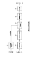
次に、図8は、図6の埋め込み符号化器3の機能的な構成例を示している。なお、この図8に示した機能的な構成は、演算処理装置34が記録媒体33に記憶されたコンピュータプログラムを実行することで実現されるようになされている。
【0070】
付加情報作成部41は、付加情報メモリ32(図6)に記憶された付加情報を読み出し、そのフォーマットを、画像に埋め込むのに適切なものに変換して、ビットプレーン変換部44に供給するようになされている。ブロック化部42は、画像メモリ31(図6)に記憶された画像を、例えば、フレーム単位で読み出し、所定のブロックに分割して、ビットプレーン化部43に供給するようになされている。
【0071】
ビットプレーン化部43は、ブロック化部42からの各ブロックを、そのブロックを構成する画素の画素値を表すビット列の各ビットごとのビットプレーンに分割し、ビットプレーン変換部44に供給するようになされている。即ち、画像を構成する各画素値に、例えば、8ビットが割り当てられているとすると、ビットプレーン化部43は、ブロック内の画素値の最下位ビット、最下位ビットから2ビット目のビット、3ビット目のビット、・・・、7ビット目のビット、最上位ビット(以下、適宜、それぞれを第1乃至第8ビットという)それぞれからなるビットプレーンを構成し、ビットプレーン変換部44に供給するようになされている。
【0072】
ビットプレーン変換部44は、付加情報作成部41から供給される付加情報にしたがって、ビットプレーン化部43からの各ブロックのビットプレーンの順番を並べ替え、これにより、画像に付加情報を埋め込み、再画像化部45に供給するようになされている。
【0073】
ここで、例えば、上述のように、画素値に8ビットが割り当てられている場合には、1のブロックからは、8のビットプレーンが得られる。そして、8のビットプレーンの並べ替え方は、8!(!は階乗を表す)通りあるから、1のブロックには、最大で、log2(8!)ビット(但し、小数点以下は切り捨て)の付加情報を埋め込むことができる。付加情報作成部41は、付加情報メモリ32に記憶された付加情報を、そのようなビット数単位のフォーマットにして、ビットプレーン交換部44に供給するようになされている。
【0074】
再画像化部45は、ビットプレーン交換部44からビットプレーンの並べ替えが行われたブロックを順次受信し、例えば、1フレーム分のブロックを受信すると、それらのブロックから1フレームの画像を再構成する。そして、再画像化部45は、その再構成した画像を符号化データとして、出力部46に出力するようになされている。出力部46は、再画像化部45からの符号化データを、所定のタイミングで出力するようになされている。
【0075】
次に、図9のフローチャートを参照して、図7の埋め込み符号化器3において行われる埋め込み符号化処理について説明する。
【0076】
まず最初に、ステップS1では、付加情報作成部41において、1フレームの画像に埋め込むことのできる分の付加情報が、付加情報メモリ32から読み出されて受信されるとともに、ブロック化部42において、1フレームの画像(ディジタル画像データ)が、画像メモリ31から読み出されて受信される。
【0077】
そして、ステップS2に進み、ブロック化部42は、1フレームの画像を所定のブロック(例えば、横×縦が4×4画素のブロック)に分割し、ビットプレーン化部43に供給する。ビットプレーン化部43では、ステップS3において、ブロック化部42からの各ブロックがビットプレーンに分割され、ビットプレーン交換部44に供給される。
【0078】
このようにビットプレーン化部43からビットプレーン変換部44に、各ブロックのビットプレーンが供給されるタイミングで、付加情報作成部41は、付加情報を、ビットプレーン変換部44に供給する。
【0079】
ビットプレーン変換部44は、ビットプレーン化部43から各ブロックのビットプレーンを受信するとともに、付加情報作成部41から付加情報を受信すると、ステップS4において、ビットプレーン化部43からの所定のブロックを注目ブロックとして、その注目ブロックのビットプレーンを、付加情報作成部41からの付加情報にしたがって並べ替え、再画像化部45に供給する。
【0080】
その後、ステップS5に進み、ビットプレーン変換部44において、1フレーム分のブロックすべてを注目ブロックとして処理(ビットプレーンを並べ替える処理)を行ったかどうかが判定され、まだ、1フレームのブロックすべてを処理していないと判定された場合、ステップS6に進み、まだ処理の対象としていないブロック(例えば、ラインスキャン順で、いま注目ブロックとなっているブロックの次のブロック)を、新たに注目ブロックとして、ステップS4に戻る。そして、付加情報作成部41からビットプレーン変換部44に対して、新たに付加情報が供給されるのを待って、ステップS4以降の処理を繰り返す。
【0081】
一方、ステップS5において、1フレームのブロックすべてを処理したと判定された場合、ステップS7に進み、再画像化部45は、ビットプレーンの並べ替えが行われた1フレーム分のブロックから、1フレームの画像を再構成し、符号化データとして、出力部46に供給する。さらに、ステップS7では、出力部46において、再画像化部45からの符号化データが出力され、処理を終了する。
【0082】
なお、以上の埋め込み符号化処理は、1フレームごとに行われる。
【0083】
以上のように、各ブロックのビットプレーンを、付加情報に対応して並べ替えることにより、各ブロックに、付加情報を埋め込む場合には、その逆の並べ替えを行うことで、元の画像を復号することができ、さらに、どのような並べ替えを行ったかということが付加情報となる。従って、画像の画質の劣化を極力なくし、かつデータ量を増加せずに、画像に付加情報を埋め込むことができる。
【0084】
即ち、画像については、ブロックを構成するビットプレーンにおけるビットどうしの相関は、基本的に、上位ビットのビットプレーンほど高い(下位ビットのビットプレーンほど低い)。従って、このような画像の相関性、即ち、ここでは、ビットプレーンを構成するビットどうしの相関を利用することにより、付加情報にしたがって並べ替えられたビットプレーンは、オーバヘッドなしで、元の順番に並べ替えることができ、さらに、その並べ替え方により、付加情報を復号ことができる。従って、その結果得られる復号画像(再生画像)には、基本的に、付加情報を埋め込むことによる画質の劣化は生じない。
【0085】
次に、図10は、図6の埋め込み符号化器3が出力する符号化データを、画像の相関性を利用して元の画像と付加情報に復号する図1の埋め込み復号器6のハードウェアの構成例を示している。
【0086】
符号化データ、即ち、付加情報が埋め込まれた画像(以下、適宜、埋め込み画像ともいう)は、入力バッファ51に供給されるようになされており、入力バッファ51は、埋め込み画像を、例えば、フレーム単位で一時記憶する。なお、入力バッファ51は、図6の画像メモリ31と同様に構成され、バンク切り替えを行うことにより、埋め込み画像が、動画であっても、そのリアルタイム処理が可能となっている。
【0087】
演算処理装置52は、記録媒体53に記憶されたプログラムを実行することで、後述するような埋め込み復号処理を行う。即ち、例えば、CD−ROMやHDでなる記録媒体53は、埋め込み復号処理を行うためのプログラムを記憶しており、演算処理装置52は、そのプログラムを実行することで、入力バッファ51に記憶された埋め込み画像を、画像の相関性を利用して元の画像と付加情報に復号する。
【0088】
具体的には、演算処理装置52は、例えば、図6の演算処理装置34と同様に、入力バッファ51に記憶されたフレームごとの埋め込み画像(ディジタル画像データ)をブロック化し、各ブロックを、そのブロックを構成する画素の画素値を表すビット列の各ビットごとのビットプレーンに分割する。さらに、演算処理装置52は、ブロックの各ビットプレーン内のビットどうしの相関を、そのビットプレーンの相関として求める。
【0089】
即ち、演算処理装置52は、例えば、図11に示すように、まず、相関を計算するビットプレーンをブロックから取り出す。そして、いま、ブロックが、例えば、上述したように、4×4画素で構成される場合、ビットプレーンも、横×縦が4×4ビットで構成されることになるが、この場合、演算処理装置52は、その4×4ビットのビットプレーンから、例えば、その中心部分の2×2ビットA,B,C,Dそれぞれを中心とした小ブロック(図11では、3×3ビットの小ブロック)を構成する。さらに、演算処理装置52は、各小ブロックについて、その中心のビットと同一の値のビットの数をカウントし、そのカウント値を、小ブロックの中心画素と、他の画素との間の相関として求める。ここで、図11においては、ビットプレーンの中心部分の2×2ビットA,B,C,Dのうちの、ビットAを中心とする小ブロックについての相関が計算されているが、ビットAは0であり、その小ブロックにおいて、ビットAと同一の値のビットは5ビット存在するから、ビットAを中心とする小ブロックについての相関は5となる。
【0090】
演算処理装置52は、他の小ブロックについても同様にして相関を求め、このようにして求めたビットA乃至Dそれぞれを中心とする小ブロックについての相関どうしを加算し、その加算値を、ビットプレーンの相関とする。
【0091】
そして、演算処理装置52は、ブロックのすべてのビットプレーンの相関を求めると、図12に示すように、相関の高いビットプレーンが最上位ビット側に位置するとともに、相関の低いビットプレーンが最下位ビット側に位置するように、即ち、相関の昇順に、ビットプレーンを並べ替えることにより、ブロックを復号する。ここで、図12では(上述の図8においても同様)、濃度の薄いビットプレーンほど、相関の高いビットプレーンを表している。
【0092】
演算処理装置52は、以上のようにして、埋め込み画像のブロックを構成するビットプレーンを昇順に並べ替えることにより元の画像のブロックを復号すると、その復号ブロックを、画像メモリ54に供給して記憶させる。さらに、演算処理装置52は、復号ブロックについて、並び替え前のビットプレーンの並びと、並び替え後のビットプレーンの並びとを比較することにより、ビットプレーンがどのように並び替えられていたかを検出し、その検出結果に基づき、ブロックのビットプレーンを並べ替えることにより埋め込まれていた付加情報を復号し、付加情報メモリ56に供給して記憶させる。
【0093】
画像メモリ54は、演算処理装置52からのブロックを受信して一時記憶し、1フレーム分のブロックを記憶すると、それを、画像処理部55に供給する。画像処理部55は、例えば、画像を表示する表示装置や、画像を記録する記録装置などでなり、画像メモリ54から供給される画像を表示し、あるいは記録等する。
【0094】
一方、付加情報メモリ56では、演算処理装置52からの付加情報が受信されて一時記憶される。そして、付加情報メモリ56に記憶された付加情報は、付加情報処理部57によって読み出され、表示その他の処理が施される。
【0095】
次に、図13は、図10の埋め込み復号器6の機能的な構成例を示している。なお、この図13に示した機能的な構成は、演算処理装置52が記録媒体53に記憶されたコンピュータプログラムを実行することで実現されるようになされている。
【0096】
入力部61は、埋め込み復号器6に供給される埋め込み画像(符号化データ)を受信し、ブロック化部62に供給するようになされている。ブロック化部62は、入力部61からの埋め込み画像を、図8のブロック化部42と同様のブロックにブロック化し、ビットプレーン化部63に供給するようになされている。ビットプレーン化部63は、ブロック化部62からのブロックを、図8のビットプレーン化部43における場合と同様にしてビットプレーンに分割し、ビットプレーン並び替え処理部64に供給するようになされている。
【0097】
ビットプレーン並び替え処理部64は、ビットプレーン化部63からのブロックを構成するビットプレーンを、その相関に基づいて並べ替えるようにことにより、元の画像のブロックを復号し、その復号ブロックを、再画像化部66に供給するようになされている。即ち、ビットプレーン並び替え処理部64は、ビットプレーン化部63からのブロックのビットプレーンを、ビットプレーン相関計算部65に供給して、例えば、図11で説明したような各ビットプレーンの相関を計算させる。さらに、ビットプレーン並び替え処理部64は、ビットプレーン相関計算部65によって求められた相関が昇順に並ぶように、ブロックのビットプレーンを並び替え、これにより、元の画像のブロックを復号する。そして、ビットプレーン並び替え処理部64は、その復号ブロックを、再画像化部66に供給するとともに、復号ブロックについての並び替え前のビットプレーンの並びと、並び替え後のビットプレーンの並びとを、付加情報取得部68に供給する。
【0098】
ビットプレーン相関計算部65は、ビットプレーン並び替え処理部64の制御にしたがい、ビットプレーンの相関を計算するようになされている。
【0099】
再画像化部66は、ビットプレーン並び替え処理部64からビットプレーンの並べ替えが行われたブロック(復号ブロック)を順次受信し、例えば、1フレーム分の復号ブロックを受信すると、それらの復号ブロックから1フレームの元の画像を再構成するようになされている。そして、再画像化部66は、その再構成した画像を復号画像として、画像出力部67に供給するようになされている。画像出力部6は、再画像化部66からの復号画像を、所定のタイミングで出力するようになされている。
【0100】
付加情報取得部68は、ビットプレーン並び替え処理部64からの、復号ブロックについての並び替え前のビットプレーンの並びと、並び替え後のビットプレーンの並びと比較することにより、ビットプレーンがどのように並び替えられていたかを検出し、その検出結果に基づき、復号ブロックのビットプレーンを並べ替えることにより埋め込まれていた付加情報を復号するようになされている。そして、復号された付加情報は、付加情報出力部69に供給されるようになされており、付加情報出力部69は、付加情報取得部68からの付加情報を、所定のタイミングで出力するようになされている。
【0101】
次に、図14のフローチャートを参照して、図13の埋め込み復号器6において行われる埋め込み復号処理について説明する。
【0102】
入力部61に、1フレームの埋め込み画像(符号化データ)が供給されると、入力部61は、ステップS11において、その1フレームの埋め込み画像を、ブロック化部62に入力する。ブロック化部62は、ステップS12において、1フレームの埋め込み画像をブロック化し、その結果得られるブロックを、ビットプレーン化部63に供給する。ビットプレーン化部63は、ステップS13において、ブロック化部62からの各ブロックをビットプレーンに分割し、ビットプレーン並び替え処理部64に供給する。
【0103】
ビットプレーン並び替え処理部64は、ステップS14において、ビットプレーン化部63からの所定のブロックを注目ブロックとして、その注目ブロックの各ビットプレーンの相関を、ビットプレーン相関計算部65に計算させる。そして、ビットプレーン並び替え処理部64は、ステップS15において、ビットプレーンの相関が昇順に並ぶように、注目ブロックのビットプレーンを並び替え、これにより、元の画像のブロックを復号する。さらに、ビットプレーン並び替え処理部64は、その復号ブロックを、再画像化部66に供給するとともに、復号ブロックについての並び替え前のビットプレーンの並び(に関する情報)と、並び替え後のビットプレーンの並び(に関する情報)とを、付加情報取得部68に供給する。
【0104】
付加情報取得部68は、ビットプレーン並び替え処理部64からの、復号ブロックについての並び替え前のビットプレーンの並びと、並び替え後のビットプレーンの並びと比較することにより、ビットプレーンがどのように並び替えられていたかを検出し、その検出結果に基づき、復号ブロックのビットプレーンを並べ替えることにより埋め込まれていた付加情報を復号し、付加情報出力部69に供給する。
【0105】
その後、ステップS16に進み、ビットプレーン並び替え処理部64において、1フレーム分のブロックすべてを注目ブロックとして処理(ビットプレーンを並べ替える処理)を行ったかどうかが判定され、まだ、1フレームのブロックすべてを処理していないと判定された場合、ステップS17に進み、図9のステップS6における場合と同様に、まだ処理の対象としていないブロックを、新たに注目ブロックとして、ステップS14に戻り、ステップS14以降の処理を繰り返す。
【0106】
一方、ステップS16において、1フレームのブロックすべてを処理したと判定された場合、ステップS18に進み、再画像化部66は、ビットプレーンの並べ替えが行われた1フレーム分の復号ブロックから、1フレームの元の画像を再構成し、復号画像として、画像出力部67に供給する。画像出力部67では、再画像化部45からの復号画像が出力され、さらに、付加情報出力部69において、付加情報取得部68からの付加情報が出力され、処理を終了する。
【0107】
なお、以上の埋め込み復号処理は、1フレームの埋め込み画像ごとに行われる。
【0108】
以上のように、付加情報が埋め込まれた画像である符号化データを、画像の相関性を利用して、元の画像と付加情報に復号するようにしたので、その復号のためのオーバヘッドがなくても、符号化データを、元の画像と付加情報に復号することができる。従って、その復号画像には、基本的に、付加情報を埋め込むことによる画質の劣化は生じない。
【0109】
次に、上述したように、画像については、ブロックを構成するビットプレーンの相関は、基本的に、上位ビットのビットプレーンほど高いが、稀にそうでないブロックがある。即ち、上位ビットのビットプレーンの相関と同一か、あるいはそれより大きい(高い)相関の下位ビットのビットプレーンが存在することがある。ここで、以下、適宜、そのような下位ビットのビットプレーンが存在するブロックを、不適合ブロックという。
【0110】
一方、埋め込み復号処理では、上述したように、埋め込み画像のブロックのビットプレーンは、相関が昇順になるように並べ替えられるから、不適合ブロックは、正しく復号することができず、また、そこに埋め込まれた付加情報も正しく復号することができない。
【0111】
そこで、埋め込み符号化処理においては、ブロックが不適合ブロックであるかどうかを判定し、ブロックが不適合ブロックである場合には、付加情報を埋め込む対象としないようにするとともに、不適合ブロックを認識するための情報(以下、適宜、ブロック情報という)を、オーバーヘッドとして、埋め込み画像に付加するようにすることができる。
【0112】
図15は、そのような埋め込み符号化処理を行う埋め込み符号化器3の機能的構成例を示している。なお、図中、図8における場合と対応する部分については、同一の符号を付してあり、以下では、その説明は、適宜省略する。即ち、図15の埋め込み符号化器3は、ブロック情報付加部47が新たに設けられている他は、図8における場合と、基本的に同様に構成されている。
【0113】
図15の実施の形態では、ビットプレーン変換部44において、注目ブロックを構成するビットプレーンの並び替えが行われる前に、その注目ブロックを構成する各ビットプレーンの相関が求められる。そして、ビットプレーン変換部44は、上位ビットのビットプレーンの相関と同一か、あるいはそれより大きい相関の下位ビットのビットプレーンが、注目ブロック内に存在するかどうかを判定し、存在しない場合、即ち、注目ブロックが不適合ブロックでない場合、図8における場合と同様に、その注目ブロックに付加情報を埋め込んで、再画像化部45に出力する。
【0114】
一方、注目ブロックが不適合ブロックである場合、ビットプレーン変換部44は、その旨を、ブロック情報付加部47に出力するとともに、不適合ブロックである注目ブロックには、付加情報を埋め込まずに、そのまま再画像化部45に出力する。
【0115】
ブロック情報付加部47は、注目ブロックが不適合ブロックである旨を、ビットプレーン変換部44から受信すると、その不適合ブロックを特定するためのブロック情報を、再画像化部45に供給し、埋め込み画像に付加させる。
【0116】
ここで、例えば、画像のブロックに、ラインスキャン順にシーケンシャルな番号を、ブロック番号として割り当ておき、ブロック情報としては、そのようなブロック番号を用いることが可能である。上述したように、ブロックが不適合ブロックである場合は稀であるから、ブロック番号をブロック情報として用いることで、埋め込み画像に付加される、オーバヘッドとしてのブロック情報は、それほど大きなデータ量にはならない。
【0117】
以上のように、埋め込み符号化器3において、埋め込み画像に、ブロック情報を付加するようにした場合には、埋め込み復号器6(図13)のビットプレーン並び替え処理部64において、ブロック情報に基づいて、注目ブロックが不適合ブロックかどうかを判定し、不適合ブロックである場合には、埋め込み復号処理の対象としないようにすることで、ブロックおよび付加情報が正しく復号されなくなることを防止することができる。
【0118】
なお、本実施の形態では、4×4画素のブロックを構成するようにしたが、ブロック情報を用いない場合においては、より多数の画素からブロックを構成する方が、画像および付加情報の復号の精度を向上させることができる。但し、ブロックを多くの画素から構成するということは、1フレームから得られるブロックの数が少なくなるから、その分、埋め込むことのできる付加情報は少なくなる。
【0119】
また、本実施の形態では、画素値を8ビットとして、ブロックを構成する8枚すべてのビットプレーンを並び替えの対象とするようにしたが、並び替えの対象とするビットプレーンは、その一部のビットプレーンだけにすることができる。例えば、最上位ビットのビットプレーンと最下位ビットのビットプレーンだけを、並び替えの対象とした場合には、最上位ビットのビットプレーンの相関が、最下位ビットのビットプレーンの相関より大きい確率は非常に高いから(最上位ビットのビットプレーンの相関が、最下位ビットのビットプレーンの相関以下であることはほとんどないから)、ブロック情報を用いなくても、画像および付加情報の復号の精度を向上させることができる。但し、並び替えの対象とするビットプレーンを少なくすると、やはり、その分、埋め込むことのできる付加情報は少なくなる。
【0120】
さらに、ビットプレーンの並び替えは、例えば、複数のビットプレーン単位で行うようにすることも可能である。即ち、本実施の形態では、ブロックは、第1ビット乃至第8ビットの8枚のビットプレーンから構成されるが、隣接する第1ビットおよび第2ビットのビットプレーン、第3ビットおよび第4ビットのビットプレーン、第5ビットおよび第6ビットのビットプレーン、第7ビットおよび第8ビットのビットプレーンの2枚のビットプレーンを1組として、その組のビットプレーン単位で並び替えを行うようにすることが可能である。この場合、各組の相関としては、その組の2枚のビットプレーンの相関の和などを用いることができる。なお、ビットプレーンの並び替えを、複数のビットプレーン単位で行う場合も、画像および付加情報の復号の精度を向上させることができるが、並び替えの場合の数が少なくなるので、やはり、その分、埋め込むことのできる付加情報は少なくなる。
【0121】
従って、ブロックの構成や、ビットプレーンの並び替えを、どのビットプレーンを対象に、どのような組み合わせで行うかは、復号の精度と、埋め込むことのできる付加情報のデータ量とのバランスを考慮して適切に決めるのが望ましい。
【0122】
また、ビットプレーンの相関の計算方法は、上述した手法に限定されるものではない。即ち、ビットプレーンの相関としては、そのビットプレーンのあるビットに注目した場合に、その注目ビットと同一の値のビットが、注目ビットのより近くにあることと、そのビット数がより多いことを反映するような値であれば、どのようなものを用いても良い。従って、0と1の数が同一の2つのビットプレーンであっても、その0と1の配置位置によって、その2つのビットプレーンの相関は異なる。即ち、2つのビットプレーンのうちの一方において、例えば、0と1とが五の目格子状に配置されており、他方において、左半分に1が配置され、残りの右半分に0が配置されている場合には、0または1それぞれの数は同一であるが、一方より、他方の方が、1または0それぞれが同一の値に近い位置にあるので、その相関は大きくなる。
【0123】
さらに、本実施の形態では、空間的に隣接する画素からブロックを構成するようにしたが、ブロックは、その他、例えば、時間的に隣接する画素から構成するようにしても良い。
【0124】
また、本実施の形態では、演算処理装置34または52に、コンピュータプログラムを実行させることで、埋め込み符号化処理または埋め込み復号処理をそれぞれ行うようにしたが、これらの処理は、それ専用のハードウェアによって行うことも可能である。
【0125】
さらに、本実施の形態では、演算処理装置34または52に実行させるコンピュータプログラムを、記録媒体33または53にそれぞれ記憶させて提供するようにしたが、このコンピュータプログラムは、その他、例えば、インターネット、地上波、衛星回線、公衆網、CATV網などの伝送媒体を介して提供するようにすることも可能である。
【0126】
また、付加情報として用いる情報は、特に限定されるものではなく、例えば、画像や、音声、テキスト、コンピュータプログラム、その他のデータを付加情報として用いることが可能である。なお、画像データベース1の画像の一部を付加情報とし、残りを、付加情報を埋め込む画像とすれば、その残りの部分に、付加情報とされた画像の一部分が埋め込まれるから、画像の圧縮が実現されることになる。
【0127】
【発明の効果】
請求項1に記載の符号化装置および請求項8に記載の符号化方法、並びに請求項16に記載の記録媒体によれば、第1のデータの少なくとも一部のデータが、所定のビット数のデータが複数集められて構成されるブロックにブロック化され、ブロックが、所定のビット数のデータを表わすビット列の各ビットごとのビットプレーンに分割される。そして、第2のデータに従って、第1のデータの少なくとも一部のデータの少なくとも1つのブロックをビットプレーン単位で入れ替えることにより、第1のデータに第2のデータに関するデータが埋め込まれて符号化される。従って、その情報が埋め込まれた画像から、画像の相関性を利用することで、元の画像と情報を復号することが可能となる。
【0128】
請求項9に記載の画像処理装置および請求項14に記載の画像処理方法、並びに請求項17に記載の提供媒体によれば、符号化データの少なくとも一部のデータが、所定のビット数のデータが複数集められて構成されるブロックにブロック化され、ブロックが、所定のビット数のデータを表わすビット列の各ビットごとのビットプレーンに分割される。そして、ブロックの各ビットプレーン内のビットどうしの相関が求められ、相関に基づいて、符号化データの少なくとも一部のデータの少なくとも1つのブロックがビットプレーン単位で入れ替えられることにより符号化データが元の第1のデータに復号されると共に、入れ替えに応じて符号化データに埋め込まれた第2のデータが復号される。
従って、画質の劣化のない画像と、元の情報を得ることが可能となる。
【0129】
請求項12に記載の画像処理システムによれば、第1のデータの少なくとも一部のデータが、所定のビット数のデータが複数集められて構成されるブロックにブロック化され、ブロックが、所定のビット数のデータを表わすビット列の各ビットごとのビットプレーンに分割される。そして、第2のデータに従って、第1のデータの少なくとも一部のデータの少なくとも1つのブロックをビットプレーン単位で入れ替えることにより、第1のデータに第2のデータに関するデータが埋め込まれて符号化される。一方、符号化データの少なくとも一部のデータが、所定のビット数のデータが複数集められて構成されるブロックにブロック化され、ブロックが、所定のビット数のデータを表わすビット列の各ビットごとのビットプレーンに分割される。そして、ブロックの各ビットプレーン内のビットどうしの相関が求められ、求められた相関に基づいて、符号化データの少なくとも一部のデータの少なくとも1つのブロックをビットプレーン単位で入れ替えることにより符号化データが元の第1のデータに復号されると共に、入れ替えに応じて符号化データに埋め込まれた第2のデータが復号される。従って、画質の劣化のない画像と、元の情報を得ることが可能となる。
【図面の簡単な説明】
【図1】本発明を適用した画像伝送システムの一実施の形態の構成例を示すブロック図である。
【図2】符号化対象の画像を示す図である。
【図3】相関性を利用した符号化/復号を説明するための図である。
【図4】連続性を利用した符号化/復号を説明するための図である。
【図5】相似性を利用した符号化/復号を説明するための図である。
【図6】図1の埋め込み符号化器3のハードウェアの構成例を示すブロック図である。
【図7】図7の演算処理装置34の処理を説明するための図である。
【図8】埋め込み符号化器3の機能的構成例を示すブロック図である。
【図9】埋め込み符号化処理を説明するためのフローチャートである。
【図10】図1の埋め込み復号器6のハードウェアの構成例を示すブロック図である。
【図11】ビットプレーンの相関の計算方法を説明するための図である。
【図12】図10の演算処理装置52の処理を説明するための図である。
【図13】埋め込み復号器6の機能的構成例を示すブロック図である。
【図14】埋め込み復号処理を説明するためのフローチャートである。
【図15】埋め込み符号化器3の他の機能的構成例を示すブロック図である。
【符号の説明】
1 画像データベース, 2 付加情報データベース, 3 埋め込み符号化器, 4 記録媒体, 5 伝送媒体, 6 埋め込み復号器, 10 符号化装置, 20 復号装置, 31 画像メモリ, 32 付加情報メモリ, 33 記録媒体, 34 演算処理装置, 35 出力バッファ, 41 付加情報作成部, 42 ブロック化部, 43 ビットプレーン化部, 44 ビットプレーン交換部, 45 再画像化部, 46 出力部, 47 ブロック情報付加部, 51 入力バッファ, 52 演算処理装置, 53 記録媒体,54 画像メモリ, 55 画像処理部, 56 付加情報メモリ, 57 付加情報処理部, 61 入力部, 62 ブロック化部, 63 ビットプレーン化部, 64 ビットプレーン並び替え部, 65 ビットプレーン相関計算部, 66 再画像化部, 67 画像出力部, 68 付加情報取得部, 69 付加情報出力部[0001]
BACKGROUND OF THE INVENTION
The present invention relates to an image processing apparatus, an image processing method, a providing medium, and an image processing system, so that information can be embedded in an image without deteriorating the image quality of a decoded image as much as possible and without increasing the amount of data. The present invention relates to an image processing apparatus, an image processing method, a providing medium, and an image processing system.
[0002]
[Prior art]
As a technique for embedding information in digital image data without increasing the amount of data, for example, the least significant bit or the lower 2 bits of a pixel value having a large value is replaced with information to be embedded. is there. This method uses the fact that the low-order bits of a pixel value with a large value do not significantly affect the image quality, and simply replaces the low-order bits with information to be embedded. Therefore, at the time of playback, the information is embedded. The image data is output as it is without restoring the lower bits. That is, it is difficult to restore the low-order bits embedded with information by simply replacing in this way, and the low-order bits of a pixel value with a large value do not significantly affect the image quality. The image data is output (displayed) in a state where information is embedded.
[0003]
[Problems to be solved by the invention]
However, with the above method, data different from the original image data is output. Therefore, the image quality of the output image has a considerable influence.
[0004]
The present invention has been made in view of such a situation, and minimizes image quality degradation and does not increase the data amount (or minimizes the increase in data amount). The information can be embedded in.
[0005]
[Means for Solving the Problems]
Claim 1The encoding device converts at least a part of the first data into a block configured by collecting a plurality of pieces of data having a predetermined number of bits.Blocking means to block and blockRepresents data with a predetermined number of bitsA dividing means for dividing the bit string into bit planes for each bit;Encoding means for embedding and encoding data relating to the second data in the first data by replacing at least one block of at least part of the first data in bit plane units according to the second data With.
[0006]
Claim8Described inIn the encoding method, at least a part of the first data is converted into a block configured by collecting a plurality of pieces of data having a predetermined number of bits.Blocking step to block, blockRepresents data with a predetermined number of bitsA division step of dividing the bit string into bit planes for each bit;An encoding step of embedding and encoding data relating to the second data in the first data by replacing at least one block of at least a part of the first data in units of bit planes according to the second data Including.
[0008]
Claim9Described inThe decoding device converts at least a part of the encoded data into a block configured by collecting a plurality of data of a predetermined number of bits.Block means to block and blockRepresents data with a predetermined number of bitsA dividing means for dividing the bit string into bit planes for each bit; a correlation calculating means for obtaining a correlation between bits in each bit plane of the block;Based on the correlation obtained by the correlation calculation means, at least one block of at least a part of the encoded data is replaced in units of bit planes, and the encoded data is decoded into the original first data and replaced. And decoding means for decoding the second data embedded in the encoded data according to.
[0009]
Claim14Described inIn the decoding method, at least a part of encoded data is converted into a block configured by collecting a plurality of data of a predetermined number of bits.Blocking step to block, blockData of a predetermined number of bitsA division step of dividing the bit sequence into bit planes for each bit of the representing bit sequence, a correlation calculation step for obtaining a correlation between bits in each bit plane of the block,Based on the correlation, at least one block of at least a part of the encoded data is replaced in units of bit planes to decode the encoded data into the original first data, and the encoded data is converted into the encoded data according to the replacement. A decoding step of decoding the embedded second data.
[0011]
Claim15Described inThe data processing system converts at least a part of the first data into a block configured by collecting a plurality of pieces of data having a predetermined number of bits.A first blocking means for blocking, and a block;Represents data with a predetermined number of bitsFirst dividing means for dividing the bit string into bit planes for each bit;According to the second data, at least one block of at least a part of the first data is replaced in units of bit planes, so that the data related to the second data is embedded in the first data and encoded.Encoding means;Encode at least a part of the encoded data into a block composed of multiple pieces of data with a predetermined number of bitsA second blocking means for blocking, and a block,Represents data with a predetermined number of bitsA second dividing means for dividing the bit string into bit planes for each bit;BlockCorrelation calculation means for obtaining a correlation between bits in each bit plane;Based on the correlation obtained by the correlation calculation means, at least one block of at least a part of the encoded data is replaced in units of bit planes, and the encoded data is decoded into the original first data and replaced. And decoding means for decoding the second data embedded in the encoded data according to.
[0012]
Claim 1In the encoding device,Blocking meansAt least a part of the first data is converted into a block configured by collecting a plurality of data of a predetermined number of bits.Blocking and dividing means, block,Represents data with a predetermined number of bitsThe bit string is divided into bit planes for each bit.The encoding means embeds data related to the second data in the first data by replacing at least one block of at least a part of the first data in units of bit planes according to the second data. It is made to become.
[0013]
Claim8Described inIn the encoding method, at least a part of the first data is converted into a block configured by collecting a plurality of pieces of data having a predetermined number of bits.Block and blockRepresents data with a predetermined number of bitsDivide the bit string into bit planes for each bit,According to the second data, at least one block of at least a part of the first data is exchanged in units of bit planes, so that the data related to the second data is embedded and encoded in the first data. ing.
[0015]
Claim9Described inIn the decryption device,Blocking meansEncode at least a part of the encoded data into a block composed of multiple pieces of data with a predetermined number of bitsBlocking and dividing means, block,Represents data with a predetermined number of bitsThe bit string is divided into bit planes for each bit. The correlation calculation means obtains the correlation between the bits in each bit plane of the block,The decoding means decodes the encoded data into the original first data by replacing at least one block of at least a part of the encoded data in units of bit planes based on the correlation obtained by the correlation calculating means. At the same time, the second data embedded in the encoded data is decoded in accordance with the replacement.
[0016]
Claim14Described inIn the decoding method, at least a part of the encoded data is converted into a block configured by collecting a plurality of data of a predetermined number of bits.Block and blockData of a predetermined number of bitsDivide into bit planes for each bit of the bit string to represent, find the correlation between the bits in each bit plane of the block,Based on the correlation, at least one block of at least a part of the encoded data is replaced in units of bit planes to decode the encoded data into the original first data, and the encoded data is converted into the encoded data according to the replacement. The embedded second data is decoded.
[0018]
Claim15In the image processing system described in
[0019]
DETAILED DESCRIPTION OF THE INVENTION
Embodiments of the present invention will be described below, but before that, in order to clarify the correspondence between the respective means of the invention described in the claims and the following embodiments, after each means, A corresponding embodiment (however, an example) is added in parentheses to describe the characteristics of the present invention, and the following is obtained.
[0020]
That is, according to claim 1The encoding device is an encoding device that encodes first data according to second data, and is configured by collecting a plurality of data of a predetermined number of bits from at least a part of the first data. BlockBlocking means for blocking (for example, the
[0021]
Claim 2The encoding deviceCorrelation calculation means (for example, bit
[0022]
Claim 4The encoding device replaces bit plane units.Block information about blocks not targetedAppend to the first data embedded with the second dataAdditional means (for example, a block
[0023]
Claim9Described inThe decoding device is a decoding device that decodes encoded data obtained by encoding first data according to second data, and at least a part of the encoded data includes a plurality of data having a predetermined number of bits. Into blocks that are assembledBlock means for blocking (for example, the
[0024]
Claim10Described inThe decryption deviceTo blockThe second data isIt further comprises determination means for determining whether or not it is embedded (for example, the bit plane
[0025]
Claim15Described inThe data processing system is a data processing system that encodes first data according to second data, and decodes the encoded data, wherein at least a part of the first data includes data having a predetermined number of bits. Multiple blocks assembledFirst blocking means for blocking (for example, the blocking unit 42 shown in FIG. 8) and the block,Represents data with a predetermined number of bitsFirst dividing means (for example, the bit plane converting unit 43 shown in FIG. 8) for dividing the bit string into bit planes for each bit;According to the second data, at least one block of at least a part of the first data is replaced in units of bit planes, so that the data related to the second data is embedded in the first data and encoded.Encoding means (for example, the bit plane exchange unit 44 shown in FIG. 8);Encode at least a part of the encoded data into a block composed of multiple pieces of data with a predetermined number of bitsThe second blocking means for blocking (for example, the blocking unit 62 shown in FIG. 13) and the block,Represents data with a predetermined number of bitsA second dividing means for dividing the bit string into bit planes for each bit (for example, the bit plane converting unit 63 shown in FIG. 13);BlockCorrelation calculation means (for example, a bit plane correlation calculation unit 65 shown in FIG. 13) for obtaining a correlation between bits in each bit plane;Based on the correlation obtained by the correlation calculation means, at least one block of at least a part of the encoded data is replaced in units of bit planes, and the encoded data is decoded into the original first data and replaced. Decoding means for decoding second data embedded in encoded data according to(For example, the bit plane
[0026]
Of course, this description does not mean that the respective means are limited to those described above.
[0027]
FIG. 1 is a diagram of an image transmission system to which the present invention is applied (a system is a logical collection of a plurality of devices, regardless of whether the devices of each configuration are in the same housing). The structural example of embodiment is shown.
[0028]
The image transmission system includes an encoding device 10 and a decoding device 20, and the encoding device 10 encodes, for example, an image as an encoding target and outputs encoded data. The decoding device 20 The encoded data is decoded into the original image.
[0029]
That is, the
[0030]
Further, the additional information database 2 stores additional information (for example, binary format digital data) as information to be embedded in the image to be encoded. The additional information stored in the additional information database 2 is read out and supplied to the embedded encoder 3.
[0031]
The embedded encoder 3 receives an image from the
[0032]
The decoding device 20 includes an embedded decoder 6 where encoded data provided via the recording medium 4 or the
[0033]
Next, the principle of encoding in the embedded encoder 3 in FIG. 1 and decoding in the embedded decoder 6 will be described.
[0034]
In general, what is called information has a bias (universality) of energy (entropy), and this bias is recognized as information (worthy information). That is, for example, an image obtained by photographing a landscape is recognized as such a landscape image because the image (pixel value of each pixel constituting the image) corresponds to the landscape. This is because the image has an energy bias, and an image having no energy bias is merely noise or the like, and is not useful as information.
[0035]
Therefore, even if some operation is performed on valuable information and the original energy bias of the information is destroyed, so to speak, some operation is performed by restoring the destroyed energy bias. Information can also be restored to the original information. That is, encoded data obtained by encoding information can be decoded into the original information by utilizing the original energy bias of the information.
[0036]
Here, examples of the energy (bias) of information include correlation, continuity, and similarity.
[0037]
Information correlation is the correlation (for example, autocorrelation between one component and another component) (for example, in the case of an image, pixels and lines constituting the image). Distance).
[0038]
That is, for example, when there is an image composed of H lines as shown in FIG. 2, the correlation between the first line from the top (first line) and other lines is generally shown in FIG. As shown in (A), the closer to the first line (the line in the upper row of the screen in FIG. 2), the larger the line, and the farther the distance from the first line (the lower line in the screen in FIG. 2). (The line of the line) becomes smaller (the correlation becomes larger as the distance from the first line is closer, and the correlation becomes smaller as the distance is farther away).
[0039]
Therefore, in the image of FIG. 2, the Mth line that is closer to the first line and the Nth line that is farther from the first line are replaced (1 <M <N ≦ H). When the correlation between a line and another line is calculated, it is as shown in FIG. 3B, for example.
[0040]
That is, in the image after replacement, the correlation with the Mth line (Nth line before replacement) close to the first line becomes small, and the correlation with the Nth line (Mth line before replacement) far from the first line. Becomes larger.
[0041]
Therefore, in FIG. 3B, the correlation bias that the correlation increases as the distance from the first line decreases and the correlation decreases as the distance from the first line decreases. However, for an image, in general, the correlation bias that the correlation increases as the distance from the first line increases, and the correlation decreases as the distance from the first line decreases, so that the broken correlation bias can be restored. That is, in FIG. 3B, the correlation with the Mth line close to the first line is small, and the correlation with the Nth line far from the first line is large because of the inherent correlation bias of the image. It is clearly unnatural (funny) and the Mth and Nth lines should be interchanged. Then, by exchanging the Mth line and the Nth line in FIG. 3B, the correlation as shown in FIG. 3A, that is, the original image can be decoded.
[0042]
Here, in the case described with reference to FIG. 2 and FIG. 3, the replacement of the line results in the encoding of the image. In the encoding, the embedded encoder 3 determines, for example, which line is to be moved and which lines are to be exchanged according to the additional information. On the other hand, in the embedded decoder 6, the encoded image, that is, the image in which the line is replaced can be restored to the original image by replacing the line with the original position using the correlation. Will be decrypted. Further, in the decoding, detecting, for example, what line has been moved or which lines have been replaced in the embedded decoder 6 will decode the additional information embedded in the image.
[0043]
Next, with regard to continuity, for example, for one line with an image, in general, as shown in FIG. 4A, a signal waveform in which a change in frequency is continuous (a frequency changes smoothly) is shown. Is observed. That is, when attention is paid to the frequency of one line, the manner of change is generally continuous.
[0044]
Therefore, a part of the signal waveform having a continuous frequency change shown in FIG. 4A is replaced with one having an extremely low frequency as shown in FIG. 4B, for example.
[0045]
In this case, the continuity that the frequency change is continuous is destroyed. However, with respect to the signal waveform, in general, the broken continuity can be restored by using the continuity that the frequency change is continuous. That is, in FIG. 4B, the frequency of a part of the signal waveform is sharply lower than the frequency of the other part, clearly from the original continuity of the signal waveform. The unnatural and extremely low frequency part should be replaced with a signal waveform having the same frequency as the frequency of other parts. Then, by performing such replacement, the signal waveform shown in FIG. 4A, that is, the original signal waveform can be decoded from the signal waveform shown in FIG. 4B.
[0046]
Here, in the case described with reference to FIG. 4, the image is encoded by changing the frequency of a part of the signal waveform greatly (by replacing the signal waveform with one having a significantly different frequency). In the encoding, the embedded encoder 3 determines, for example, which part of the signal waveform the frequency is to be changed greatly and how much the frequency is to be changed according to the additional information. Become. On the other hand, the embedded decoder 6 uses the continuity to return the encoded signal, that is, the signal waveform having a part of a significantly different frequency to the original signal waveform. Will be decrypted. Further, in the decoding, the embedded decoder 6 embedded, for example, detecting which part of the signal waveform has changed greatly, how much the frequency has changed, etc. The additional information is decoded.
[0047]
Next, regarding similarity, it is known that, for example, an enlarged image of an image obtained by photographing a landscape can be generated using fractal (self-similarity). That is, for example, when an image of the sea as shown in FIG. 5A is enlarged using a fractal, an image (enlarged image) having the same characteristics as the original image can be obtained. Images taken of landscapes and the like are similar.
[0048]
Therefore, a part of the image obtained by photographing the sea shown in FIG. 5A is a part of the image obtained by photographing the forest (see FIG. 5B), for example, as shown in FIG. Replace with (hatched part).
[0049]
In this case, in FIG. 5B, the similarity of the image obtained by photographing the sea is destroyed for the portion replaced with the image obtained by photographing the forest. However, for images taken of the sea, in general, any part of the image that has been enlarged can be destroyed by using the similarity that an image having the same characteristics as the image taken of the sea can be obtained. Sex can be restored. That is, in FIG. 5B, part of the image obtained by photographing the sea is an image obtained by photographing the forest. This is clearly unnatural in view of the original similarity of the image obtained by photographing the sea. Therefore, the part that is an image of the forest should be replaced with an image having the same characteristics as the surrounding sea image. By performing such replacement, the sea-only image shown in FIG. 5A, that is, the original image can be decoded from the image shown in FIG. 5B.
[0050]
Here, in the case described with reference to FIG. 5, replacing a part of the sea image with the forest image encodes the image. In the encoding, the embedded encoder 3 determines, for example, which part (position on the screen) of the sea image is replaced with the forest image according to the additional information. On the other hand, the embedded decoder 6 uses the similarity to restore the encoded signal, that is, the sea image having a part of the forest image, to the original sea image. Will be decoded. Further, in the decoding, detecting, for example, which part of the sea image has been replaced with the forest image in the embedded decoder 6 decodes the embedded additional information.
[0051]
As described above, the embedded encoder 3 encodes the image in accordance with the additional information so that decoding can be performed using the energy bias of the image to be encoded, and the encoded data , The embedded decoder 6 can decode the encoded data into the original image and the additional information without using overhead for decoding by using the energy bias of the image. it can.
[0052]
Further, since the additional information is embedded in the encoding target image, the image is different from the original state, and thus the encoding target image is encrypted without overhead. be able to.
[0053]
Furthermore, a completely reversible digital watermark can be realized. That is, in the conventional digital watermark, for example, the low-order bits of the pixel value that do not significantly affect the image quality are simply changed to values corresponding to the digital watermark. In this case, the low-order bits are changed to the original values. It is difficult to return. Therefore, the image quality of the decoded image deteriorates not a little due to the change of the lower bits as the digital watermark. On the other hand, when the encoded data is decoded using the energy bias of the original image, the original image and additional information can be obtained, and therefore the additional information is used as a digital watermark. Thus, the image quality of the decoded image does not deteriorate due to the digital watermark.
[0054]
Further, since the embedded additional information can be extracted by decoding the image from the encoded data, the side information can be provided without any overhead along with the image encoding result. In other words, since the additional information can be embedded in the image without the overhead for extracting the additional information, the encoded data obtained as a result of the embedding is compressed (embedded compressed) by the amount of the additional information. be able to. Therefore, for example, if half of a certain image is to be encoded and the other half is additional information, the remaining half of the image can be embedded in the half of the image to be encoded. The image will be compressed to 1/2.
[0055]
Furthermore, since the encoded data is decoded using a so-called statistic, that is, an energy bias of the original image, it is highly resistant to errors. That is, robust encoding (statistical encoding) that is highly robust encoding can be realized.
[0056]
In addition, since the encoded data is decoded using the energy bias of the original image, the more characteristic the energy bias is, that is, for example, the higher the activity of the image, or The lower the redundancy, the more additional information can be embedded. Here, as described above, the encoded data obtained as a result of embedding the additional information can be said to be compressed by the amount of the additional information. From the viewpoint of this compression, the information to be encoded is According to the method of encoding the information according to the additional information (embedded encoding method) so that decoding can be performed using the bias of energy possessed, the higher the activity of the image, or the The lower the redundancy, the higher the compression ratio. In this regard, the embedded coding method is significantly different from the conventional coding method (in the conventional coding method, for example, the MPEG (Moving Picture Experts Group) method), the higher the activity of the image, or the The lower the redundancy, the lower the compression ratio).
[0057]
Furthermore, for example, as described above, an image is to be encoded, and as additional information, for example, audio of a medium different from the image is used, and the image is provided using the audio as a key. It becomes possible. That is, on the encoding device 10 side, for example, the voice “open sesame” uttered by the contractor is embedded in the image as additional information, and on the decoding device 20 side, the user utters the speech “open sesame”. Then, speaker recognition is performed using the voice and the voice embedded in the image. As a result of speaker recognition, it is possible to automatically present an image only when the user is a contractor. In this case, the sound as the additional information can use the sound waveform itself, not so-called feature parameters.
[0058]
In addition, for example, while audio is an encoding target, audio is provided using an image as a key by using, for example, an image of a medium different from audio as additional information (for example, , Face recognition voice response). That is, on the encoding device 10 side, for example, an image of the user's face is embedded in the voice as a response to the user, and on the decoding device 20 side, the user's face is photographed and matched with the resulting image. By outputting the voice in which the face image is embedded, it is possible to realize a voice response system that performs a different voice response for each user.
[0059]
Furthermore, it is also possible to embed information of the same medium in information of a certain medium, such as embedding sound in an audio or embedding an image in an image. Alternatively, if the voice and face image of the contractor are embedded in the image, the image is presented only when the voice and face image of the user match those embedded in the image. In other words, a double key system can be realized.
[0060]
In addition, for example, it is possible to embed the other in one of the synchronized images and sounds constituting the television broadcast signal. In this case, the information of different media is integrated. Integrated coding can be realized.
[0061]
Further, in the embedded coding system, as described above, the information can be embedded with more additional information, as the information has a characteristic of energy bias. Therefore, for example, it is possible to control the total amount of data by adaptively selecting one of the two types of information that has a characteristic in energy bias and embedding the other in the selected one. It becomes. That is, it is possible to absorb the other information amount between two pieces of information. As a result of controlling the total amount of data in this way, information transmission (environmentally responsive network transmission) with a data amount suitable for the transmission band and usage status of the transmission path and other transmission environments becomes possible.
[0062]
Further, for example, by embedding a reduced image of an image in an image (or by embedding a sound obtained by thinning out the sound), so-called hierarchical encoding (lower hierarchy) is performed without increasing the amount of data. (Encoding in which information of the above is reduced is used as an upper layer).
[0063]
Furthermore, for example, by embedding an image as a key for searching for an image in the image, a database for searching for an image based on the image as the key can be realized.
[0064]
Next, FIG. 6 shows a hardware configuration of the embedded encoder 3 in FIG. 1 in the case of performing embedded encoding in which additional information is embedded in an image so that it can be restored using the correlation of the image. An example is shown.
[0065]
An image (image data) supplied from the
[0066]
The
[0067]
The encoded data output by the
[0068]
The
[0069]
Next, FIG. 8 shows a functional configuration example of the embedded encoder 3 of FIG. The functional configuration shown in FIG. 8 is realized by the
[0070]
The additional
[0071]
The bit
[0072]
The bit
[0073]
Here, for example, when 8 bits are assigned to the pixel value as described above, 8 bit planes are obtained from one block. And how to rearrange 8 bitplanes is 8! (! Represents the factorial)2Additional information of (8!) Bits (however, the fractional part is rounded down) can be embedded. The additional
[0074]
The
[0075]
Next, the embedded encoding process performed in the embedded encoder 3 of FIG. 7 will be described with reference to the flowchart of FIG.
[0076]
First, in step S1, additional information that can be embedded in an image of one frame is read from the
[0077]
In step S 2, the blocking
[0078]
In this way, the additional
[0079]
When the bit
[0080]
Thereafter, the process proceeds to step S5, where it is determined whether or not all the blocks for one frame have been processed as the target block (processing for rearranging the bit planes) in the bit
[0081]
On the other hand, if it is determined in step S5 that all the blocks of one frame have been processed, the process proceeds to step S7, where the
[0082]
The above embedded encoding process is performed for each frame.
[0083]
As described above, by rearranging the bit planes of each block corresponding to the additional information, when embedding additional information in each block, the original image is decoded by performing the reverse rearrangement. Furthermore, what sort of sort is performed becomes additional information. Therefore, it is possible to embed additional information in an image while minimizing degradation of the image quality of the image and without increasing the amount of data.
[0084]
That is, for an image, the correlation between bits in the bit planes constituting the block is basically higher for the upper bit plane (lower for the lower bit plane). Therefore, by using the correlation between the images, that is, the correlation between the bits constituting the bit plane, the bit planes rearranged according to the additional information in the original order without overhead. The additional information can be rearranged, and the additional information can be decoded by the rearrangement method. Accordingly, in the decoded image (reproduced image) obtained as a result, image quality deterioration due to embedding additional information basically does not occur.
[0085]
Next, FIG. 10 shows the hardware of the embedded decoder 6 in FIG. 1 that decodes the encoded data output from the embedded encoder 3 in FIG. 6 into the original image and additional information using the correlation of the images. The example of a structure is shown.
[0086]
The encoded data, that is, an image in which additional information is embedded (hereinafter also referred to as an embedded image as appropriate) is supplied to an
[0087]
The
[0088]
Specifically, the
[0089]
That is, for example, as shown in FIG. 11, the
[0090]
The
[0091]
Then, when the
[0092]
As described above, the
[0093]
The
[0094]
On the other hand, the
[0095]
Next, FIG. 13 shows a functional configuration example of the embedded decoder 6 of FIG. The functional configuration shown in FIG. 13 is realized when the
[0096]
The
[0097]
The bit plane
[0098]
The bit plane
[0099]
The
[0100]
The additional
[0101]
Next, the embedded decoding process performed in the embedded decoder 6 of FIG. 13 will be described with reference to the flowchart of FIG.
[0102]
When one frame of embedded image (encoded data) is supplied to the
[0103]
In step S14, the bit plane
[0104]
The additional
[0105]
Thereafter, the process proceeds to step S16, where it is determined whether or not the bit plane
[0106]
On the other hand, when it is determined in step S16 that all the blocks of one frame have been processed, the process proceeds to step S18, and the
[0107]
The above embedded decoding process is performed for each embedded image of one frame.
[0108]
As described above, encoded data, which is an image in which additional information is embedded, is decoded into the original image and additional information using the correlation between images, so there is no overhead for decoding. However, the encoded data can be decoded into the original image and additional information. Accordingly, the decoded image basically does not deteriorate in image quality due to the embedded additional information.
[0109]
Next, as described above, for an image, the correlation of bit planes constituting a block is basically higher for a bit plane of higher bits, but there are rarely blocks that are not so. That is, there may be a lower-bit bit plane having a correlation that is the same as or higher (higher) than the higher-bit bit plane. Here, hereinafter, a block in which such a lower-order bit plane exists appropriately is referred to as a non-conforming block.
[0110]
On the other hand, in the embedded decoding process, as described above, the bit planes of the blocks of the embedded image are rearranged so that the correlation is in ascending order, so that the nonconforming block cannot be correctly decoded and is embedded therein. The added information cannot be decoded correctly.
[0111]
Therefore, in the embedded coding process, it is determined whether or not the block is a nonconforming block. If the block is a nonconforming block, the additional information is not embedded and the nonconforming block is recognized. Information (hereinafter, appropriately referred to as block information) can be added to the embedded image as overhead.
[0112]
FIG. 15 shows a functional configuration example of the embedded encoder 3 that performs such embedded encoding processing. In the figure, portions corresponding to those in FIG. 8 are denoted by the same reference numerals, and description thereof will be omitted below as appropriate. That is, the embedded encoder 3 in FIG. 15 is basically configured in the same manner as in FIG. 8 except that a block
[0113]
In the embodiment of FIG. 15, the bit
[0114]
On the other hand, if the target block is a non-conforming block, the bit
[0115]
When receiving from the bit
[0116]
Here, for example, sequential numbers in the order of line scan are assigned to the blocks of the image as block numbers, and such block numbers can be used as the block information. As described above, since it is rare that the block is a nonconforming block, the block information as overhead added to the embedded image by using the block number as the block information does not have a very large data amount.
[0117]
As described above, when block information is added to the embedded image in the embedded encoder 3, the bit plane
[0118]
In this embodiment, a 4 × 4 pixel block is configured. However, when block information is not used, a block composed of a larger number of pixels is more suitable for decoding an image and additional information. Accuracy can be improved. However, if a block is composed of a large number of pixels, the number of blocks obtained from one frame is reduced, and accordingly, additional information that can be embedded is reduced.
[0119]
In this embodiment, the pixel value is set to 8 bits, and all the 8 bit planes constituting the block are to be rearranged. However, the bit planes to be rearranged are a part of them. Can only be a bit plane. For example, if only the most significant bit plane and the least significant bit plane are to be reordered, the probability that the correlation between the most significant bit plane is greater than the least significant bit plane correlation is Because it is very high (the correlation of the bit plane of the most significant bit is less than the correlation of the bit plane of the least significant bit), the accuracy of decoding the image and additional information can be improved without using block information. Can be improved. However, if the number of bit planes to be rearranged is reduced, the additional information that can be embedded is reduced accordingly.
[0120]
Further, the rearrangement of bit planes can be performed in units of a plurality of bit planes, for example. That is, in this embodiment, the block is composed of eight bit planes of the first bit to the eighth bit, but the adjacent bit planes of the first and second bits, the third bit, and the fourth bit. The bit planes of the first bit plane, the fifth bit plane, the sixth bit plane, and the seventh bit plane and the eighth bit plane are set as one set, and rearrangement is performed in units of the bit planes of the set. It is possible. In this case, as the correlation of each set, the sum of correlations of the two bit planes of the set can be used. It should be noted that even when rearrangement of bit planes is performed in units of a plurality of bit planes, the accuracy of decoding images and additional information can be improved. However, since the number of rearrangements decreases, the corresponding amount is also reduced. Less additional information can be embedded.
[0121]
Therefore, the block configuration and the bit plane rearrangement for which bit planes and in which combinations are performed take into account the balance between the accuracy of decoding and the amount of additional information that can be embedded. It is desirable to decide appropriately.
[0122]
Further, the method of calculating the correlation of the bit plane is not limited to the above-described method. In other words, as the correlation of the bit plane, when attention is paid to a bit in the bit plane, the bit having the same value as the bit of interest is closer to the bit of interest and the number of bits is larger. Any value may be used as long as it reflects the value. Therefore, even if two bit planes have the same number of 0s and 1s, the correlation between the two bit planes differs depending on the arrangement positions of the 0s and 1s. That is, in one of the two bit planes, for example, 0 and 1 are arranged in a five-lattice pattern, and on the other hand, 1 is arranged in the left half and 0 is arranged in the remaining right half. In this case, the numbers of 0 and 1 are the same, but the correlation is greater because the other is closer to the same value in the other than 1 in the other.
[0123]
Furthermore, in the present embodiment, the block is composed of spatially adjacent pixels, but the block may be composed of, for example, temporally adjacent pixels.
[0124]
In this embodiment, the
[0125]
Further, in the present embodiment, the computer program to be executed by the
[0126]
The information used as the additional information is not particularly limited, and for example, an image, sound, text, a computer program, or other data can be used as the additional information. If a part of the image in the
[0127]
【The invention's effect】
Claim 1EncoderAnd claims8Described inEncoding methodAnd claims16Described inrecoding mediaAccording toAt least a part of the first data is a block configured by collecting a plurality of data of a predetermined number of bits.Blocked, the block isRepresents data with a predetermined number of bitsThe bit string is divided into bit planes for each bit. AndAccording to the second data, at least one block of at least a part of the first data is exchanged in units of bit planes, whereby the data related to the second data is embedded in the first data and encoded.Therefore, it is possible to decode the original image and information by using the correlation of the image from the image in which the information is embedded.
[0128]
Claim9And an image processing apparatus according to claim 114And an image processing method according to claim 1.17According to the media described inAt least a part of the encoded data is a block configured by collecting a plurality of data of a predetermined number of bits.Blocked, the block isData of a predetermined number of bitsThe bit string to be represented is divided into bit planes for each bit. And the correlation between the bits in each bit plane of the block is calculated,Based on the correlation, at least one block of at least a part of the encoded data is replaced in units of bit planes so that the encoded data is decoded into the original first data and encoded according to the replacement. The second data embedded in the data is decoded.
Therefore, it is possible to obtain an image with no deterioration in image quality and original information.
[0129]
According to the image processing system of claim 12,At least a part of the first data is a block configured by collecting a plurality of data of a predetermined number of bits.Blocked, the block isRepresents data with a predetermined number of bitsThe bit string is divided into bit planes for each bit. AndAccording to the second data, at least one block of at least a part of the first data is exchanged in units of bit planes, whereby the data related to the second data is embedded in the first data and encoded.on the other hand,At least a part of the encoded data is a block configured by collecting a plurality of data of a predetermined number of bits.Blocked, the block isRepresents data with a predetermined number of bitsThe bit string is divided into bit planes for each bit. AndBlockCorrelation between bits in each bit plane is obtained,Based on the obtained correlation, the encoded data is decoded into the original first data by replacing at least one block of at least a part of the encoded data in units of bit planes. Second data embedded in encoded data is decoded. Therefore, it is possible to obtain an image with no deterioration in image quality and original information.
[Brief description of the drawings]
FIG. 1 is a block diagram illustrating a configuration example of an embodiment of an image transmission system to which the present invention is applied.
FIG. 2 is a diagram illustrating an image to be encoded.
FIG. 3 is a diagram for explaining encoding / decoding using correlation.
FIG. 4 is a diagram for explaining encoding / decoding using continuity.
FIG. 5 is a diagram for explaining encoding / decoding using similarity.
6 is a block diagram illustrating a hardware configuration example of the embedded encoder 3 in FIG. 1;
7 is a diagram for explaining processing of the
FIG. 8 is a block diagram illustrating a functional configuration example of an embedded encoder 3;
FIG. 9 is a flowchart for explaining embedded encoding processing;
10 is a block diagram showing a hardware configuration example of the embedded decoder 6 in FIG. 1. FIG.
FIG. 11 is a diagram for explaining a bit plane correlation calculation method;
12 is a diagram for explaining processing of the
13 is a block diagram illustrating a functional configuration example of an embedded decoder 6. FIG.
FIG. 14 is a flowchart for explaining embedded decoding processing;
15 is a block diagram illustrating another functional configuration example of the embedded encoder 3. FIG.
[Explanation of symbols]
DESCRIPTION OF
Claims (17)
前記第1のデータの少なくとも一部のデータを、所定のビット数のデータが複数集められて構成されるブロックにブロック化するブロック化手段と、
前記ブロックを、前記所定のビット数のデータを表わすビット列の各ビットごとのビットプレーンに分割する分割手段と、
前記第2のデータに従って、前記第1のデータの少なくとも一部のデータの少なくとも1つのブロックをビットプレーン単位で入れ替えることにより、前記第1のデータに前記第2のデータに関するデータを埋め込んで符号化する符号化手段と
を備える符号化装置。 An encoding device that encodes first data according to second data,
Blocking means for blocking at least a part of the first data into blocks configured by collecting a plurality of data of a predetermined number of bits ;
Dividing means for dividing the block into bit planes for each bit of a bit string representing the predetermined number of bits of data ;
According to the second data, at least one block of at least a part of the first data is replaced in units of bit planes, so that the data related to the second data is embedded in the first data and encoded. Encoding means to
An encoding device comprising:
前記符号化手段は、最上位ビットのビットプレーンから最下位ビットのビットプレーンの方向に、前記相関が昇順に並んでいるブロックのみを、ビットプレーン単位の入れ替えを行う対象とする
請求項1に記載の符号化装置。Correlation calculating means for obtaining a correlation between bits in each bit plane of the block;
Said encoding means, in the direction of the bit plane of the least significant bit from the bit plane of the MSB, according to claim 1, wherein the correlation is only blocks are arranged in ascending order, and subjected to the exchange of units of bit planes Encoding device.
請求項2に記載の符号化装置。 It said encoding means encoding apparatus according to the block by the correlation have the same bit plane interchanging exclude claims 2 to subjected to the bit plane units.
請求項1に記載の符号化装置。The encoding apparatus according to claim 1, further comprising an adding unit that adds block information related to a block that is not targeted for replacement in the bit plane unit to the first data in which the second data is embedded .
請求項1に記載の符号化装置。The encoding device according to claim 1.
前記符号化手段は、前記第2のデータに従って、前記第1の画像データの少なくとも1つの画像ブロックをビットプレーン単位で入れ替えることにより、前記第1の画像データに前記第2のデータに関するデータを埋め込むThe encoding unit embeds data related to the second data in the first image data by replacing at least one image block of the first image data in bit plane units according to the second data.
請求項1に記載の符号化装置。The encoding device according to claim 1.
請求項6に記載の符号化装置。The encoding device according to claim 6.
前記第1のデータの少なくとも一部のデータを、所定のビット数のデータが複数集められて構成されるブロックにブロック化するブロック化ステップと、
前記ブロックを、前記所定のビット数のデータを表わすビット列の各ビットごとのビットプレーンに分割する分割ステップと、
前記第2のデータに従って、前記第1のデータの少なくとも一部のデータの少なくとも1つのブロックをビットプレーン単位で入れ替えることにより、前記第1のデータに前記第2のデータに関するデータを埋め込んで符号化する符号化ステップと
を含む符号化方法。 An encoding method for encoding first data according to second data,
A block forming step of blocking at least a part of the first data into blocks configured by collecting a plurality of pieces of data having a predetermined number of bits ;
A division step of dividing the block into bit planes for each bit of a bit string representing the predetermined number of bits of data ;
According to the second data, at least one block of at least a part of the first data is replaced in units of bit planes, so that the data related to the second data is embedded in the first data and encoded. Encoding step to
An encoding method including:
前記符号化データの少なくとも一部のデータを、所定のビット数のデータが複数集められて構成されるブロックにブロック化するブロック手段と、
前記ブロックを、前記所定のビット数のデータを表わすビット列の各ビットごとのビットプレーンに分割する分割手段と、
前記ブロックの各ビットプレーン内のビットどうしの相関を求める相関演算手段と、
前記相関演算手段により求められた前記相関に基づいて、前記符号化データの前記少なくとも一部のデータの少なくとも1つのブロックをビットプレーン単位で入れ替えることにより前記符号化データを元の前記第1のデータに復号すると共に、前記入れ替えに応じて前記符号化データに埋め込まれた前記第2のデータを復号する復号手段と
を備える復号装置。 A decoding device that decodes encoded data in which first data is encoded according to second data,
Block means for blocking at least a part of the encoded data into a block configured by collecting a plurality of data of a predetermined number of bits ;
Dividing means for dividing the block into bit planes for each bit of a bit string representing the predetermined number of bits of data ;
Correlation calculating means for obtaining a correlation between bits in each bit plane of the block;
Based on the correlation obtained by the correlation calculation means, the encoded data is replaced with the first data by replacing at least one block of the at least some of the encoded data in units of bit planes. And decoding means for decoding the second data embedded in the encoded data in accordance with the replacement
A decoding device comprising:
前記復号手段は、前記判定手段により前記第2のデータが埋め込まれていると判定された前記ブロックを、前記ビットプレーン単位で入れ替える対象の前記ブロックとする
請求項9に記載の復号装置。Determination means for determining whether or not the second data is embedded in the block;
The decoding means sets the block determined to be embedded by the determination means as the block to be replaced in units of the bit plane.
The decoding device according to claim 9 .
請求項10に記載の復号装置。It said determining means, on the basis of the block information on whether the second data to each block is embedded, determines whether the second data in the block is embedded
The decoding device according to claim 10 .
請求項9に記載の復号装置。The decoding device according to claim 9.
請求項9に記載の復号装置。 The decoding means determines a replacement pattern of the at least one block of the encoded data in units of the bit plane, and sets a value corresponding to the replacement pattern as second data.
The decoding device according to claim 9 .
前記符号化データの少なくとも一部のデータを、所定のビット数のデータが複数集められて構成されるブロックにブロック化するブロック化ステップと、
前記ブロックを、前記所定のビット数のデータを表わすビット列の各ビットごとのビットプレーンに分割する分割ステップと、
前記ブロックの各ビットプレーン内のビットどうしの相関を求める相関演算ステップ
前記相関に基づいて、前記符号化データの前記少なくとも一部のデータの少なくとも1つのブロックをビットプレーン単位で入れ替えることにより前記符号化データを元の前記第1のデータに復号すると共に、前記入れ替えに応じて前記符号化データに埋め込まれた前記第2のデータを復号する復号ステップと
を含む復号方法。 A decoding method for decoding encoded data obtained by encoding first data according to second data,
A block forming step for blocking at least a part of the encoded data into blocks configured by collecting a plurality of pieces of data of a predetermined number of bits ;
A division step of dividing the block into bit planes for each bit of a bit string representing the predetermined number of bits of data ;
Correlation calculation step for obtaining a correlation between bits in each bit plane of the block
Based on the correlation, the encoded data is decoded into the original first data by replacing at least one block of the at least part of the encoded data in bit plane units, and the replacement is performed. And a decoding step of decoding the second data embedded in the encoded data accordingly;
A decoding method including:
前記第1のデータの少なくとも一部のデータを、所定のビット数のデータが複数集められて構成されるブロックにブロック化する第1のブロック化手段と、
前記ブロックを、前記所定のビット数のデータを表わすビット列の各ビットごとのビットプレーンに分割する第1の分割手段と、
前記第2のデータに従って、前記第1のデータの少なくとも一部のデータの少なくとも1つのブロックをビットプレーン単位で入れ替えることにより、前記第1のデータに前記第2のデータに関するデータを埋め込んで符号化する符号化手段と、
前記符号化データの少なくとも一部のデータを、所定のビット数のデータが複数集められて構成されるブロックにブロック化する第2のブロック化手段と、
前記ブロックを、前記所定のビット数のデータを表わすビット列の各ビットごとのビットプレーンに分割する第2の分割手段と、
前記ブロックの各ビットプレーン内のビットどうしの相関を求める相関演算手段と、
前記相関演算手段により求められた前記相関に基づいて、前記符号化データの前記少なくとも一部のデータの少なくとも1つのブロックをビットプレーン単位で入れ替えることにより前記符号化データを元の前記第1のデータに復号すると共に、前記入れ替えに応じて前記符号化データに埋め込まれた前記第2のデータを復号する復号手段と
を備えるデータ処理システム。 A data processing system that encodes first data according to second data and decodes the encoded data,
First blocking means for blocking at least a part of the first data into blocks configured by collecting a plurality of data of a predetermined number of bits ;
First dividing means for dividing the block into bit planes for each bit of a bit string representing the predetermined number of bits of data ;
According to the second data, at least one block of at least a part of the first data is replaced in units of bit planes, so that the data related to the second data is embedded in the first data and encoded. and encoding means for,
A second blocking means for blocking at least a part of the encoded data into blocks configured by collecting a plurality of data of a predetermined number of bits ;
Second dividing means for dividing the block into bit planes for each bit of a bit string representing the predetermined number of bits of data ;
A correlation computing means for finding correlations of bits each other of each bit in the plane of said block,
Based on the correlation obtained by the correlation calculation means, the encoded data is replaced with the first data by replacing at least one block of the at least some of the encoded data in units of bit planes. And decoding means for decoding the second data embedded in the encoded data in accordance with the replacement
A data processing system comprising:
前記第1のデータの少なくとも一部のデータを、所定のビット数のデータが複数集められて構成されるブロックにブロック化するブロック化ステップと、
前記ブロックを、前記所定のビット数のデータを表わすビット列の各ビットごとのビットプレーンに分割する分割ステップと、
前記第2のデータに従って、前記第1のデータの少なくとも一部のデータの少なくとも1つのブロックをビットプレーン単位で入れ替えることにより、前記第1のデータに前記第2のデータに関するデータを埋め込んで符号化する符号化ステップと
をコンピュータに実行させるプログラムが記録されている記録媒体。 A recording medium storing a computer-controllable program for encoding first data according to second data,
A block forming step of blocking at least a part of the first data into blocks configured by collecting a plurality of pieces of data having a predetermined number of bits ;
A division step of dividing the block into bit planes for each bit of a bit string representing the predetermined number of bits of data ;
According to the second data, at least one block of at least a part of the first data is replaced in units of bit planes, so that the data related to the second data is embedded in the first data and encoded. and the encoding step to
Recording medium which is recorded a program causing a computer to execute the.
前記符号化データの少なくとも一部のデータを、所定のビット数のデータが複数集められて構成されるブロックにブロック化するブロック化ステップと、
前記ブロックを、前記所定のビット数のデータを表わすビット列の各ビットごとのビットプレーンに分割する分割ステップと、
前記ブロックの各ビットプレーン内のビットどうしの相関を求める相関演算ステップと、
前記相関に基づいて、前記符号化データの前記少なくとも一部のデータの少なくとも1つのブロックをビットプレーン単位で入れ替えることにより前記符号化データを元の前記第1のデータに復号すると共に、前記入れ替えに応じて前記符号化データに埋め込まれた前記第2のデータを復号する復号ステップと
をコンピュータに実行させるプログラムが記録されている記録媒体。 A recording medium storing a computer-controllable program for decoding encoded data in which first data is encoded according to second data,
A block forming step for blocking at least a part of the encoded data into blocks configured by collecting a plurality of pieces of data of a predetermined number of bits ;
A division step of dividing the block into bit planes for each bit of a bit string representing the predetermined number of bits of data ;
A correlation calculation step for obtaining a correlation between bits in each bit plane of the block;
Based on the correlation, the encoded data is decoded into the original first data by replacing at least one block of the at least part of the encoded data in bit plane units, and the replacement is performed. And a decoding step of decoding the second data embedded in the encoded data accordingly;
Recording medium which is recorded a program causing a computer to execute the.
Priority Applications (4)
| Application Number | Priority Date | Filing Date | Title |
|---|---|---|---|
| JP33370098A JP3924967B2 (en) | 1998-11-25 | 1998-11-25 | Encoding apparatus and method, decoding apparatus and method, recording medium, and data processing system |
| EP19990309323 EP1005230A3 (en) | 1998-11-25 | 1999-11-23 | Coding apparatus and method, decoding apparatus and method, data processing system, and storage medium |
| US09/448,543 US6215421B1 (en) | 1998-11-25 | 1999-11-23 | Coding apparatus and method, decoding apparatus and method, data processing system, and storage medium |
| KR19990052626A KR100817732B1 (en) | 1998-11-25 | 1999-11-25 | Coding apparatus and method, decoding apparatus and method, data processing system, and storage medium |
Applications Claiming Priority (1)
| Application Number | Priority Date | Filing Date | Title |
|---|---|---|---|
| JP33370098A JP3924967B2 (en) | 1998-11-25 | 1998-11-25 | Encoding apparatus and method, decoding apparatus and method, recording medium, and data processing system |
Publications (3)
| Publication Number | Publication Date |
|---|---|
| JP2000165644A JP2000165644A (en) | 2000-06-16 |
| JP2000165644A5 JP2000165644A5 (en) | 2005-11-10 |
| JP3924967B2 true JP3924967B2 (en) | 2007-06-06 |
Family
ID=18268997
Family Applications (1)
| Application Number | Title | Priority Date | Filing Date |
|---|---|---|---|
| JP33370098A Expired - Fee Related JP3924967B2 (en) | 1998-11-25 | 1998-11-25 | Encoding apparatus and method, decoding apparatus and method, recording medium, and data processing system |
Country Status (4)
| Country | Link |
|---|---|
| US (1) | US6215421B1 (en) |
| EP (1) | EP1005230A3 (en) |
| JP (1) | JP3924967B2 (en) |
| KR (1) | KR100817732B1 (en) |
Families Citing this family (29)
| Publication number | Priority date | Publication date | Assignee | Title |
|---|---|---|---|---|
| JP4131349B2 (en) * | 1998-12-09 | 2008-08-13 | ソニー株式会社 | Data conversion apparatus, data conversion method, recording medium, and data conversion system |
| US7212677B2 (en) * | 2000-01-11 | 2007-05-01 | Minolta Co., Ltd. | Coder, coding method, program, and image forming apparatus for improving image data compression ratio |
| JP3888823B2 (en) * | 2000-02-14 | 2007-03-07 | 松下電器産業株式会社 | Semiconductor integrated circuit |
| JP3535444B2 (en) * | 2000-03-27 | 2004-06-07 | 株式会社エーエスエー・システムズ | Information concealment system using printed matter |
| JP4099951B2 (en) * | 2000-03-30 | 2008-06-11 | コニカミノルタビジネステクノロジーズ株式会社 | Image processing apparatus, image forming apparatus, information embedding method, and program for embedding additional information in image data |
| US7440584B2 (en) * | 2000-03-31 | 2008-10-21 | Intel Corporation | System and method for marking data and document distribution |
| US6985632B2 (en) * | 2000-04-17 | 2006-01-10 | Canon Kabushiki Kaisha | Image processing system, image processing apparatus, and image processing method |
| GB2366926A (en) | 2000-09-06 | 2002-03-20 | Sony Uk Ltd | Combining material and data |
| JP2002084539A (en) * | 2000-09-07 | 2002-03-22 | Asa Systems:Kk | Technique for applying bit-plane segmentation steganography to successively approximated and compressed data |
| JP4214440B2 (en) * | 2000-10-19 | 2009-01-28 | ソニー株式会社 | Data processing apparatus, data processing method, and recording medium |
| AU2002214613A1 (en) * | 2000-11-08 | 2002-05-21 | Digimarc Corporation | Content authentication and recovery using digital watermarks |
| JP3682222B2 (en) * | 2000-12-11 | 2005-08-10 | 株式会社東芝 | Digital watermark detection apparatus, digital watermark detection method, and recording medium |
| JP3587168B2 (en) * | 2001-01-23 | 2004-11-10 | 日本ビクター株式会社 | Digital watermark information embedding device, embedding method, digital watermark information reproducing device and reproducing method |
| JP4556087B2 (en) * | 2001-03-22 | 2010-10-06 | ソニー株式会社 | DATA PROCESSING DEVICE, DATA PROCESSING METHOD, PROGRAM, AND PROGRAM RECORDING MEDIUM |
| KR100440085B1 (en) * | 2001-08-21 | 2004-07-14 | 한국전자통신연구원 | Apparatus for inserting watermarks using bitplane informations and method thereof, and apparatus for detecting whether the watermarked digital data was modulated and method thereof |
| US6968072B1 (en) * | 2001-12-06 | 2005-11-22 | Pixim, Inc. | Image sensor with built-in steganographic and watermarking functions |
| AU2002357259A1 (en) * | 2001-12-13 | 2003-07-09 | Digimarc Corporation | Reversible watermarking |
| US7515730B2 (en) * | 2001-12-13 | 2009-04-07 | Digimarc Corporation | Progressive image quality control using watermarking |
| US8059815B2 (en) * | 2001-12-13 | 2011-11-15 | Digimarc Corporation | Transforming data files into logical storage units for auxiliary data through reversible watermarks |
| US7006662B2 (en) * | 2001-12-13 | 2006-02-28 | Digimarc Corporation | Reversible watermarking using expansion, rate control and iterative embedding |
| US7187780B2 (en) * | 2001-12-13 | 2007-03-06 | Digimarc Corporation | Image processing methods using reversible watermarking |
| JP3961870B2 (en) * | 2002-04-30 | 2007-08-22 | 株式会社リコー | Image processing method, image processing apparatus, and image processing program |
| US7519819B2 (en) * | 2002-05-29 | 2009-04-14 | Digimarc Corporatino | Layered security in digital watermarking |
| WO2005076985A2 (en) * | 2004-02-04 | 2005-08-25 | Digimarc Corporation | Digital watermarking image signals on-chip and photographic travel logs through digital watermarking |
| JP4576318B2 (en) * | 2005-10-26 | 2010-11-04 | 富士通株式会社 | Encoding device |
| EP2412162A4 (en) * | 2009-03-27 | 2014-06-25 | Agency Science Tech & Res | Data embedding methods, embedded data extraction methods, truncation methods, data embedding devices, embedded data extraction devices and truncation devices |
| KR101538491B1 (en) * | 2013-11-04 | 2015-07-22 | 박배억 | Method and apparatus for using image as a means of storing and moving supplementary data |
| CN104144277B (en) * | 2014-07-23 | 2017-05-10 | 西安空间无线电技术研究所 | Multi-path image lossless hidden transmission method |
| CN104891670A (en) * | 2015-05-07 | 2015-09-09 | 戴祺又 | Environment-friendly type high-efficiency house refuse covering agent and preparation method thereof |
Family Cites Families (5)
| Publication number | Priority date | Publication date | Assignee | Title |
|---|---|---|---|---|
| DE3650771D1 (en) * | 1985-12-13 | 2002-08-14 | Canon Kk | Image processing device |
| US5309526A (en) * | 1989-05-04 | 1994-05-03 | At&T Bell Laboratories | Image processing system |
| US5734752A (en) * | 1996-09-24 | 1998-03-31 | Xerox Corporation | Digital watermarking using stochastic screen patterns |
| US5915027A (en) * | 1996-11-05 | 1999-06-22 | Nec Research Institute | Digital watermarking |
| US6052205A (en) * | 1997-02-14 | 2000-04-18 | Ricoh Company, Ltd. | Image data encoding/decoding method and apparatus configured to compress both natural gray scale images and binary images |
-
1998
- 1998-11-25 JP JP33370098A patent/JP3924967B2/en not_active Expired - Fee Related
-
1999
- 1999-11-23 EP EP19990309323 patent/EP1005230A3/en not_active Withdrawn
- 1999-11-23 US US09/448,543 patent/US6215421B1/en not_active Expired - Lifetime
- 1999-11-25 KR KR19990052626A patent/KR100817732B1/en not_active IP Right Cessation
Also Published As
| Publication number | Publication date |
|---|---|
| EP1005230A2 (en) | 2000-05-31 |
| JP2000165644A (en) | 2000-06-16 |
| US6215421B1 (en) | 2001-04-10 |
| KR100817732B1 (en) | 2008-03-31 |
| EP1005230A3 (en) | 2000-06-21 |
| KR20000035679A (en) | 2000-06-26 |
Similar Documents
| Publication | Publication Date | Title |
|---|---|---|
| JP3924967B2 (en) | Encoding apparatus and method, decoding apparatus and method, recording medium, and data processing system | |
| JP4822304B2 (en) | Image processing apparatus, image processing method, and recording medium | |
| US6931156B2 (en) | Coding apparatus and method, decoding apparatus and method, data processing system, storage medium and signal | |
| US7738711B2 (en) | Coding apparatus and method, decoding apparatus and method, data processing system, storage medium, and signal | |
| JP3991249B2 (en) | Encoding apparatus and encoding method, decoding apparatus and decoding method, information processing apparatus and information processing method, and recording medium | |
| JPH1155662A (en) | Image processor | |
| JP4182603B2 (en) | Encoding apparatus and encoding method, decoding apparatus and decoding method, recording medium, and data processing apparatus | |
| US6738492B1 (en) | Coding apparatus and method, decoding apparatus and method, data processing system, storage medium, and signal | |
| JP4556147B2 (en) | Decoding device, decoding method, recording medium, and data processing device | |
| KR100777144B1 (en) | Coding apparatus and method, decoding apparatus and method, data processing system, storage medium, and recording medium | |
| JP3527454B2 (en) | Image decoding method, image decoding device, and recording medium storing image decoding program | |
| JP4099687B2 (en) | Image processing apparatus, image processing method, and medium | |
| JP4092608B2 (en) | Image processing apparatus, image processing method, and program storage medium | |
| JP4374712B2 (en) | Data processing apparatus, data processing method, and recording medium | |
| JP3464660B2 (en) | Image encoding method, image encoding device, image decoding method, and image decoding device | |
| JP4548434B2 (en) | Data processing apparatus, data processing method, and recording medium | |
| JPH11196416A (en) | Device and method for encoding, device and method for decoding and recording medium |
Legal Events
| Date | Code | Title | Description |
|---|---|---|---|
| A521 | Request for written amendment filed |
Free format text: JAPANESE INTERMEDIATE CODE: A523 Effective date: 20050817 |
|
| A621 | Written request for application examination |
Free format text: JAPANESE INTERMEDIATE CODE: A621 Effective date: 20050817 |
|
| A521 | Request for written amendment filed |
Free format text: JAPANESE INTERMEDIATE CODE: A523 Effective date: 20050916 |
|
| A977 | Report on retrieval |
Free format text: JAPANESE INTERMEDIATE CODE: A971007 Effective date: 20070201 |
|
| TRDD | Decision of grant or rejection written | ||
| A01 | Written decision to grant a patent or to grant a registration (utility model) |
Free format text: JAPANESE INTERMEDIATE CODE: A01 Effective date: 20070206 |
|
| A61 | First payment of annual fees (during grant procedure) |
Free format text: JAPANESE INTERMEDIATE CODE: A61 Effective date: 20070219 |
|
| FPAY | Renewal fee payment (event date is renewal date of database) |
Free format text: PAYMENT UNTIL: 20100309 Year of fee payment: 3 |
|
| FPAY | Renewal fee payment (event date is renewal date of database) |
Free format text: PAYMENT UNTIL: 20110309 Year of fee payment: 4 |
|
| FPAY | Renewal fee payment (event date is renewal date of database) |
Free format text: PAYMENT UNTIL: 20110309 Year of fee payment: 4 |
|
| FPAY | Renewal fee payment (event date is renewal date of database) |
Free format text: PAYMENT UNTIL: 20120309 Year of fee payment: 5 |
|
| FPAY | Renewal fee payment (event date is renewal date of database) |
Free format text: PAYMENT UNTIL: 20130309 Year of fee payment: 6 |
|
| FPAY | Renewal fee payment (event date is renewal date of database) |
Free format text: PAYMENT UNTIL: 20130309 Year of fee payment: 6 |
|
| FPAY | Renewal fee payment (event date is renewal date of database) |
Free format text: PAYMENT UNTIL: 20140309 Year of fee payment: 7 |
|
| R250 | Receipt of annual fees |
Free format text: JAPANESE INTERMEDIATE CODE: R250 |
|
| R250 | Receipt of annual fees |
Free format text: JAPANESE INTERMEDIATE CODE: R250 |
|
| LAPS | Cancellation because of no payment of annual fees |