JP3920071B2 - An apparatus that enables the position of the tape head to be aligned with the medium transfer direction by visual recognition. - Google Patents
An apparatus that enables the position of the tape head to be aligned with the medium transfer direction by visual recognition. Download PDFInfo
- Publication number
- JP3920071B2 JP3920071B2 JP2001317591A JP2001317591A JP3920071B2 JP 3920071 B2 JP3920071 B2 JP 3920071B2 JP 2001317591 A JP2001317591 A JP 2001317591A JP 2001317591 A JP2001317591 A JP 2001317591A JP 3920071 B2 JP3920071 B2 JP 3920071B2
- Authority
- JP
- Japan
- Prior art keywords
- alignment
- head
- medium
- transport direction
- write
- Prior art date
- Legal status (The legal status is an assumption and is not a legal conclusion. Google has not performed a legal analysis and makes no representation as to the accuracy of the status listed.)
- Expired - Fee Related
Links
Images


Classifications
-
- G—PHYSICS
- G11—INFORMATION STORAGE
- G11B—INFORMATION STORAGE BASED ON RELATIVE MOVEMENT BETWEEN RECORD CARRIER AND TRANSDUCER
- G11B5/00—Recording by magnetisation or demagnetisation of a record carrier; Reproducing by magnetic means; Record carriers therefor
- G11B5/008—Recording on, or reproducing or erasing from, magnetic tapes, sheets, e.g. cards, or wires
-
- G—PHYSICS
- G11—INFORMATION STORAGE
- G11B—INFORMATION STORAGE BASED ON RELATIVE MOVEMENT BETWEEN RECORD CARRIER AND TRANSDUCER
- G11B5/00—Recording by magnetisation or demagnetisation of a record carrier; Reproducing by magnetic means; Record carriers therefor
- G11B5/48—Disposition or mounting of heads or head supports relative to record carriers ; arrangements of heads, e.g. for scanning the record carrier to increase the relative speed
- G11B5/488—Disposition of heads
- G11B5/4893—Disposition of heads relative to moving tape
-
- G—PHYSICS
- G11—INFORMATION STORAGE
- G11B—INFORMATION STORAGE BASED ON RELATIVE MOVEMENT BETWEEN RECORD CARRIER AND TRANSDUCER
- G11B5/00—Recording by magnetisation or demagnetisation of a record carrier; Reproducing by magnetic means; Record carriers therefor
- G11B5/48—Disposition or mounting of heads or head supports relative to record carriers ; arrangements of heads, e.g. for scanning the record carrier to increase the relative speed
- G11B5/56—Disposition or mounting of heads or head supports relative to record carriers ; arrangements of heads, e.g. for scanning the record carrier to increase the relative speed with provision for moving the head support for the purpose of adjusting the position of the head relative to the record carrier, e.g. manual adjustment for azimuth correction or track centering
-
- G—PHYSICS
- G11—INFORMATION STORAGE
- G11B—INFORMATION STORAGE BASED ON RELATIVE MOVEMENT BETWEEN RECORD CARRIER AND TRANSDUCER
- G11B5/00—Recording by magnetisation or demagnetisation of a record carrier; Reproducing by magnetic means; Record carriers therefor
- G11B5/48—Disposition or mounting of heads or head supports relative to record carriers ; arrangements of heads, e.g. for scanning the record carrier to increase the relative speed
- G11B5/58—Disposition or mounting of heads or head supports relative to record carriers ; arrangements of heads, e.g. for scanning the record carrier to increase the relative speed with provision for moving the head for the purpose of maintaining alignment of the head relative to the record carrier during transducing operation, e.g. to compensate for surface irregularities of the latter or for track following
- G11B5/584—Disposition or mounting of heads or head supports relative to record carriers ; arrangements of heads, e.g. for scanning the record carrier to increase the relative speed with provision for moving the head for the purpose of maintaining alignment of the head relative to the record carrier during transducing operation, e.g. to compensate for surface irregularities of the latter or for track following for track following on tapes
-
- G—PHYSICS
- G11—INFORMATION STORAGE
- G11B—INFORMATION STORAGE BASED ON RELATIVE MOVEMENT BETWEEN RECORD CARRIER AND TRANSDUCER
- G11B5/00—Recording by magnetisation or demagnetisation of a record carrier; Reproducing by magnetic means; Record carriers therefor
- G11B5/008—Recording on, or reproducing or erasing from, magnetic tapes, sheets, e.g. cards, or wires
- G11B5/00813—Recording on, or reproducing or erasing from, magnetic tapes, sheets, e.g. cards, or wires magnetic tapes
- G11B5/00817—Recording on, or reproducing or erasing from, magnetic tapes, sheets, e.g. cards, or wires magnetic tapes on longitudinal tracks only, e.g. for serpentine format recording
- G11B5/00821—Recording on, or reproducing or erasing from, magnetic tapes, sheets, e.g. cards, or wires magnetic tapes on longitudinal tracks only, e.g. for serpentine format recording using stationary heads
- G11B5/00826—Recording on, or reproducing or erasing from, magnetic tapes, sheets, e.g. cards, or wires magnetic tapes on longitudinal tracks only, e.g. for serpentine format recording using stationary heads comprising a plurality of single poles or gaps or groups thereof operative at the same time
Description
【0001】
【発明の属する技術分野】
本発明は全般に、テープヘッドを、テープヘッドを横切って移送される媒体の移送方向と正確に位置合わせするための少なくとも1つの位置合わせ素子を含むテープヘッドに関する。より具体的には、本発明は、テープヘッドの書込み素子と一体に形成され、書込み素子が、テープヘッドを横切って移送される媒体の移送方向と正確に位置合わせできるようにテープヘッドの磁軸と位置合わせされる、少なくとも1つの位置合わせ素子を含むテープヘッドに関する。
【0002】
【従来の技術】
1つのパスにおいて、テープの全長に沿って1つあるいは複数の個別のサーボバンドにサーボコードを書き込むサーボライタヘッドがよく知られている。サーボコードは、サーボライタヘッド上に形成される書込み素子(磁気変換器)によってテープ上に書き込まれる。書込み素子は、たとえば、シェブロンパターンのような所定のパターンを有する。サーボバンドは、あるピッチだけ離れており、近接するサーボバンド間の領域は、たとえば、データ記憶のような用途のために確保される。典型的には、個別のサーボバンドの少なくとも2つのサーボバンド上にあるサーボコードはサーボ信号を生成するために用いられ、そのサーボ信号は、テープの長さに沿った1つあるいは複数の個別のデータバンドに対して、データの読出し、あるいは書込みを行うために読出し/書込みヘッド上のデータ素子を正確な位置に位置合わせするために用いられる。そのデータバンドは、サーボバンド間の領域に配置される。サーボコードは、テープの製造中にテープ上に予め記録され、個別のサーボバンドが、テープの幅にわたる所定の場所に配置される。それらの所定の場所は、テープのためのフォーマット仕様によって定義することができる。たとえば、フォーマット仕様は、サーボバンドの数、データバンドの数、テープの幅にわたる互いに対するその位置を決定する。
【0003】
より多くのデータがテープ上の同じ量の物理的な空間に格納されるので、より良好な基準および位置精度が必要である。格納されるデータの量を増やすために、書込みおよび読出し素子の機構サイズをミクロンあるいはサブミクロンの寸法にまで縮小し、テープの幅にわたって収容することができるデータバンドの数を増加させるようにしなければならない。テープをサーボ書込みするには、書込みおよびデータ素子の機構サイズが縮小するのに応じて、一層高い精度が要求される。サーボコードがテープに書き込まれる際に、サーボコードは書込み素子のパターンの中央に配置され、直線状にテープを走査するために、できるだけテープの移動方向に垂直でなければならない。
【0004】
理想的には、テープがサーボライタヘッド上を移送されるとき、書込み素子のためのパターンは、ヘッド上のテープの移動方向に対して正確に向けられるべきである。典型的には、その向きはテープの移動方向に垂直である。大部分の応用形態では、サーボライタヘッダは、たとえば、フィールド交換可能ユニット(以下、FRU)のような取付具あるいは治具に取り付けられる。FRUは、サーボライタヘッドを、テープに対して固定された方向に配置する。FRUは、サーボライタヘッドをテープおよび/またはテープの移動方向に対して位置合わせできるように、サーボライタヘッド、FRUあるいはその両方の位置がテープに対して調整されるように設計することができる。
【0005】
サーボライタヘッドを位置合わせすることを試みる従来の方法は、サーボライタヘッド上に視認可能な指示子を配置することを含む。典型的には、視認可能な指示子は、サーボライタヘッドの磁軸の場所を近似するように配置される。視認可能な指示子がテープの移動方向に垂直に、あるいはテープエッジのうちの一方あるいは両方に垂直になるように見えるまで、テープに対して方位角を調整することにより、サーボライタヘッドが位置合わせされる。視認可能な指示子を形成するための方法は、道具を用いてサーボライタヘッドにマークを付し、視認可能な指示子を形成することを含む。たとえば、刻み(あるいは切り込み)を入れたマークを用いて、視認可能な指示子を形成することができる。
【0006】
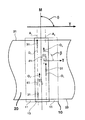
図1のaおよび図1のbを参照すると、従来技術のテープヘッド200は、テープヘッド200の磁軸250に沿って配置される1つあるいは複数の書込み変換器241を備える。相対するエッジ221および223を有するテープ220は、テープヘッド200に接触し、移送方向Dにテープヘッド200を横切って移送される。視認可能な指示子215がテープヘッド200上に形成され、テープヘッド200上の全体の基準点を規定するように機能する。典型的には、視認可能な指示子215は磁軸250の近似的な場所を規定する。テープヘッド200の位置は、視認可能な指示子215が、約90°の角度を表す角度α 1によって示されるように、移送方向Dに概ね垂直に見えるまで、テープ220に対して調整される(251)。視認可能な指示子215が抱える1つの欠点は、テープヘッド200上の指示子215の場所が全体の基準点、すなわち磁軸250の近似にしかならないことである。テープヘッド200が製造された後に、視認可能な指示子215がテープヘッド200上に形成されるので、視認可能な指示子215を磁軸と正確に位置合わせすることは、不可能ではないにしても非常に難しい。それゆえ、視認可能な指示子215を通る軸217は、磁軸250と同一直線上にはなく、その結果として、磁軸250は、移送方向Dに垂直ではない方位角a3(すなわちα 3≠90°)を有することになる。軸217は磁軸250から変位し(図1のbを参照)、磁軸250とは平行でない可能性が非常に高い。結果として、視認可能な指示子215は、書込み変換器241を移送方向Dと正確に位置合わせするために用いることができる正確な指示子とはならない。さらに、書込み変換器241がミクロンあるいはサブミクロン範囲の機構サイズを有する場合には、視認可能な指示子215によって引き起こされるわずかな位置合わせ誤差であっても、書込み変換器241と移送方向Dとの実質的な位置合わせ不良が生じるようになる。
【0007】
また、サーボライタヘッドを位置合わせするための従来の試みは、サーボライタヘッドをテープと位置合わせするために、サーボライタヘッドの相対する辺を用いることも含んでいた。このアプローチは、サーボライタヘッドの相対する辺が、その相対する辺が互いに平行に、かつサーボライタヘッドの磁軸に平行および/または垂直になるように製造されていることを想定している。しかしながら、実際には、サーボライタヘッドは、鋸歯等を用いて切断される場合がある。結果として、相対する辺は厳密には互いに平行にはならないであろう。たとえば、サーボライタヘッドは、長方形を有するのではなく、平行四辺形の形状を有するであろう。
【0008】
図2のaおよび図2のbを参照すると、従来技術のテープヘッド300は、互いに平行ではなく、かつテープヘッド300の磁軸350に平行あるいは垂直ではない相対する辺301および303を有する(すなわちテープヘッド300は、長方形ではない形状を有する)。テープヘッド300は、磁軸350に沿って配置される1つあるいは複数の書込み変換器341を備える。相対するテープエッジ321および323を有するテープ320はテープヘッド300と接触し、移送方向Dにテープヘッド300を横切って移送される。一方の辺301上の片側の軸305は、相対する辺301の一方あるいは両方が、図2のbの角度α 2によって示されるように、相対するテープエッジ(321および323)の一方あるいは両方と垂直になるように見えるまで調整される(351)。しかしながら、相対する辺301は互いに平行ではないので、角度α 2がテープエッジ(321および323)に垂直になるように見えるとき、磁軸350は移送方向Dに垂直にはならない。これは、片側の軸305が磁軸350に平行ではないことに一部起因することに留意されたい。結果として、磁軸350は、片側の軸305が角度a2であるとき、移送方向Dに垂直ではない角度a4をなす(すなわち、α 4≠90°である)。同様に、相対する辺303を用いて、相対する辺303のいずれか一方が、相対するテープエッジ321および323の一方あるいは両方に平行になるように、テープヘッド300を位置合わせする場合には、相対する辺301がテープエッジ(321および323)に平行になるように見えるとき、磁軸350は、移送方向Dに垂直にはならないであろう。それゆえ、磁軸350が移送方向Dに垂直でない場合には、書込み変換器341も移送方向Dに垂直にはならない。
【0009】
サーボライタヘッドの応用形態では、上記の位置合わせの問題の結果、製造中にテープ上に書き込まれるサーボコードの方位角に誤差が生じるようになる。たとえば、リニアテープオープン(LTO)フォーマットでは、サーボコードは、5つのバンドにおいてテープ上に書き込まれる。データヘッドのテープへの位置合わせは、近接するサーボバンド間のバンド対バンドの位置合わせを用いて達成される。その近接するサーボバンド内のサーボコードを用いて、近接するバンド内のサーボコードの平均値である位置信号を導出する。サーボライタヘッドの書込み変換器が移送方向に位置合わせされないとき、近接するサーボバンドのうちの1つのサーボコードが、別の近接するサーボバンド内のサーボコードより先にテープ上に書き込まれるであろう(すなわち、テープ上で視認されるとき、1つのサーボバンドが他のサーボバンドより先に書き込まれるように見えるであろう)。結果として、近接するサーボバンド内のサーボコードは、位置信号を導出するために用いられる平均値にスキュー(バンド間スキュー)を発生させる固有の方位角誤差を有する。バンド間スキューによって、バンドID不良が発生するようになるか、あるいはバンド間スキューによって、データヘッドを位置決めするために長い時間がかかるようになる。
【0010】
上記のように、変換器の機構サイズを縮小するには、上記の従来技術を用いて達成することができる位置合わせ精度より高い精度が要求される。たとえば、サーボコードが、テープに書き込まれる、あるいはテープから読み出されるデータより前にテープ上に予め記録される同一面サーボ(same-surface-servo application)の応用形態では、サーボバンドがテープの移動方向に平行で、かつサーボコードがテープの移動方向に垂直に位置合わせされるように、サーボコードがテープに正確に位置合わせされることが重要である。サーボコードがテープに正確に位置合わせされない場合には、サーボコードは、近接するデータバンド内のデータを占有および/または干渉するようになる。データがテープに書き込まれる前に、サーボコードがテープ上に予め記録されるので、結果的な位置合わせ不良は、テープが製造された後に補正することはできない。それゆえ、製造中に正確な位置合わせを行うことが不可欠である。
【0011】
【発明が解決しようとする課題】
それゆえ、テープヘッド上の書込み素子を、テープヘッドを横切って移送されるテープの移送方向と正確に位置合わせすることが必要とされる。さらに、バンド間スキューが著しく低減あるいは排除されるように、テープヘッド上の書込み素子を、テープヘッドを横切って移送されるテープの移送方向と正確に位置合わせすることが必要とされる。また、テープヘッドの相対する辺が平行であるか、あるいはテープヘッドに物理的にマークを付すことによらずに、書込み素子をテープの移送方向と全体的に位置合わせすることが必要とされる。
【0012】
【課題を解決するための手段】
概して、本発明は、少なくとも1つの書込み素子と、書込み素子と一体に形成される1つあるいは複数の位置合わせ素子とを含むテープヘッドにおいて具現される。位置合わせ素子および書込み素子は、テープヘッドの磁軸に対して固定された向きを有する。書込み素子および位置合わせ素子はいずれも、テープヘッドに供給される書込み電流によって誘発される磁界を生成するように機能する。書込み素子からの磁界は、移送方向においてテープヘッドを横切って移送される媒体上の書込みバンドに、複数の書込み遷移部(transition)を書き込む。同様に、各位置合わせ素子からの磁界は、媒体上の位置合わせバンドに複数の位置合わせ遷移部を書き込む。移送方向に対する書込み素子の正確な位置合わせは、個別の位置合わせバンド内の位置合わせ遷移部を観測し、その後、その観測された位置合わせ遷移部が、書込み素子が移送方向に位置合わせされたことを示すまで、磁軸と移送方向との間のヘッド対媒体角を調整することにより達成することができる。
【0013】
本発明の一実施形態では、テープヘッドは、書込み素子と一体に形成される1つの位置合わせ素子を含み、書込み素子および位置合わせ素子はいずれも、磁軸に対して固定された向きを有する。位置合わせ素子からの磁界が、媒体上の1つの位置合わせバンドに複数の位置合わせ遷移部を書き込む。移送方向に対する書込み素子の正確な位置合わせは、その1つの位置合わせバンド内の位置合わせ遷移部を観測し、その後、その観測された位置合わせ遷移部が、書込み素子が移送方向に位置合わせされたことを示すまで、磁軸と移送方向との間のヘッド対媒体角を調整することにより達成することができる。
【0014】
移送方向に対する書込み素子の位置合わせが、テープヘッドの形状には依存しないため、互いに対して平行ではないテープヘッドの辺によって引き起こされる上記の位置合わせ不良は、本発明によって解決される。それゆえ、テープヘッドの辺は、互いに対して平行である必要はない。さらに、移送方向に対する書込み素子の位置合わせが、媒体上の位置合わせ遷移部を観測することにより判定されるので、視認可能な指示子が磁軸と位置合わせされないことに起因すると考えられる位置合わせ不良も、本発明によって解決される。それゆえ、テープ上に不完全な視認可能な指示子を設けることは、実質的に必要ではなくなる。
【0015】
さらに、より高い位置合わせ精度に対する要求、およびより良好な基準および位置精度に対する要求は、本発明の位置合わせ素子によって解決される。書込み素子および位置合わせ素子はいずれも磁軸に対して固定された向きを有するので、移送方向に対する書込み素子の向きは、媒体上に書き込まれる位置合わせ遷移部の向きから判定することができる。
【0016】
バンド間スキューに関連する問題は、バンド間スキューが移送方向に対する書込み素子の位置合わせ不良によって引き起こされるので、本発明の位置合わせ素子によって排除、あるいは著しく低減することができる。結果として、サーボバンド間の方位角誤差は、書込み素子が、媒体上に書き込まれる位置合わせ遷移部によって示されるような移送方向と位置合わせされるときに、無視することができる。
【0017】
別の実施形態では、本発明は、書込み素子と一体に形成される水平および/または垂直素子を備えることができる。水平素子は、互いに平行で、かつ磁軸に垂直である。媒体の相対するエッジに対するテープヘッドの全体的な視認による位置合わせは、水平素子が、媒体の相対するエッジのいずれか一方あるいは両方に対して平行に見えるようになるまで、ヘッド対媒体角を調整することにより達成することができる。移送方向に対するテープヘッドの全体的な視認による位置合わせが、垂直素子が移送方向に垂直に、あるいは相対するエッジの一方または両方に垂直に見えるまで、ヘッド対媒体角を調整することにより達成できるように、垂直素子は磁軸と同一直線上にあり、かつ磁軸の場所を正確に指示する。水平および垂直素子は、全体的な視認による位置合わせを達成するために、個別に、あるいは組み合わせて用いることができる。
【0018】
視認可能な指示子を用いることに関する上記の問題は、本発明の垂直素子によって解決される。第一に、垂直素子が磁軸の場所の視認可能な正確な指示を与えるように、垂直素子は書込み素子と一体に形成され、かつ磁軸と同一直線上にある。それゆえ、従来技術の視認可能な指示子とは異なり、テープヘッドが製造された後に、磁軸の場所を推測あるいは近似する必要はない。第二に、垂直素子は磁軸と同一直線上にあるため、それらは磁軸に平行でもある。結果として、垂直素子が、移送方向に対して、あるいは相対するエッジの一方あるいは両方に対して視覚的に垂直である場合には、磁軸は、移送方向と全体的に垂直に位置合わせされている。同様に、水平素子は磁軸に垂直であるので、水平素子が相対するエッジあるいは移送方向に視覚的に平行である場合には、磁軸も、移送方向と全体的に垂直に位置合わせされている。
【0019】
さらに、相対するテープエッジおよび/または移送方向に対する磁軸の全体的な位置合わせが、テープヘッドの形状、あるいはテープヘッドにおける平行な辺の欠如とは無関係であるので、テープヘッドの辺が互いに平行ではない場合の上記の問題は、本発明の水平および垂直素子によって実質的に意味がなくなる。
【0020】
本発明のさらに別の実施形態では、位置合わせ素子によって生成される位置合わせ遷移部を用いて、媒体の移送方向に対するテープヘッドの位置合わせを達成する。位置合わせ遷移部からある信号が導出され、その信号を用いて、媒体の移送方向に対するテープヘッドの方位角を調整する。位置合わせ遷移部は、他に使用するために予め指定されている媒体上の領域を占有することができ、位置合わせ遷移部は、その後、テープヘッドによって上書きすることもできる。
【0021】
それゆえ、テープに対してデータの読み出しおよび/または書き込みを行うテープヘッドを、テープの移送方向と位置合わせするための要求は、本発明の位置合わせ素子によって取り扱われる。たとえば、データを記憶するために用いられることになるテープの製造中に、位置合わせ素子を含むテープヘッドを用いて、テープ上に位置合わせ遷移部を書き込むことができる。製造後、テープは、データの読出しおよび/または書込みを行うように構成されるデータヘッドを横切って移送されることができる。データヘッドは、位置合わせ遷移部を読み出す変換器を備えることができ、そこからの信号を処理し、かつ使用して、データヘッドがテープの移送方向と位置合わせされるように、データヘッドの方位角を調整することができる。位置合わせ遷移部は、テープに永続的に書き込まれることができるか、あるいはその後、データヘッドによって上書きすることができる。
【0022】
【発明の実施の形態】
本発明の他の態様および利点は、例を用いて本発明の原理を示す、添付の図面とともに取り上げられる以下の詳細な説明から明らかになるであろう。
【0023】
以下の詳細な説明およびいくつかの図面では、同様の素子は同様の参照番号で特定される。
【0024】
例示するための図面に示されるように、本発明は、テープヘッドの少なくとも1つの書込み素子を、テープヘッドを横切って移送される媒体の移送方向と正確に位置合わせするための装置において具現される。テープヘッドは少なくとも1つの位置合わせ素子を備える。位置合わせ素子は書込み素子と一体に形成され、位置合わせ素子および書込み素子はいずれも、テープヘッドの磁軸に対して第1の固定された向きを有する。さらに、位置合わせ素子は、第1の可変のピッチだけ近接する位置合わせ素子から離隔して配置されることができる。書込み素子および位置合わせ素子は、テープヘッドに供給される書込み電流によって誘発される磁界を生成する。書込み素子からの磁界は、媒体上に複数の書込み遷移部を書き込む。その書き込まれた遷移部は、媒体上の書込みバンドを画定する。同様に、位置合わせ素子からの磁界は、媒体上に複数の位置合わせ遷移部を書き込み、それにより媒体上の位置合わせバンドを画定する。位置合わせ遷移部は、移送方向に対して記録された向きを有する。位置合わせ素子は、書込み素子に対して、媒体上に書き込まれる位置合わせ遷移部が、書き込まれた遷移部と干渉せず、かつ書き込まれた遷移部を上書きしないように配置することができる。さらに、位置合わせ遷移部は、他に使用するために予め指定されている媒体上の領域を占有しないように、媒体上に配置することができる。移送方向に対する書込み素子の正確な位置合わせは、位置合わせバンド内の位置合わせ遷移部を観測し、位置合わせ遷移部の記録された向きが、書込み素子が移送方向に対して好ましい向きを有することを示すまで、テープヘッドの磁軸と媒体の移送方向との間のヘッド対媒体角を調整することにより得られる。
【0025】
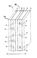
ここで、図3、図4、図5および図6が参照され、その図面では、テープヘッド10は、少なくとも1つの書込み素子41(2つの書込み素子41が示される)と、少なくとも1つの位置合わせ素子31(3つが示される)とを備える。位置合わせ素子31は、以下に説明されるように、テープヘッド10の製造中に書込み素子41と一体に形成される。位置合わせ素子31は、第1の可変のピッチ(P1、P2)だけ互いから離隔して配置される。第1の可変のピッチ(P1、P2)は、位置合わせ素子31の中央の間で測定することができる(図3に示される)か、あるいは、第1の可変のピッチ(P1、P2)を測定するために、たとえば、1つの位置合わせ素子31の上端から別の位置合わせ素子31の下端までの距離のような、いくつかの他の基準点を選択することができる。好ましい実施形態では、第1の可変のピッチ(P1、P2)は互いに等しい(すなわち、P1=P2)。しかしながら、第1の可変のピッチ(P1、P2)は等しい必要はなく、位置合わせ素子31間で変更することができる。たとえば、ピッチP1は、ピッチP2より長くすることができ、その逆にすることもできる。位置合わせ素子31および書込み素子41は、磁界(図示せず)を生成するように構成される。磁界は、テープヘッド10に供給される書込み電流(図示せず)によって誘発される。書込み電流を供給するために必要とされる原理および電子装置は、テープヘッド技術においてよく知られている。たとえば、コイルを形成するために、テープヘッド10内に形成されるアパーチャ(図示せず)を通して導体(図示せず)を引き回すことができる。導体に供給される電流が、磁界を誘発することができる。
【0026】
図4では、書込み素子41からの磁界が、媒体20上の複数の書込み遷移部43を書き込む。媒体20は、相対するエッジ21および23を備え、移送方向Tにテープヘッド10を横切って移送される。媒体20には、たとえば、データ記憶の応用形態において用いられるタイプのような磁気テープを用いることができる。書込み遷移部43は、媒体20上の書込みバンド45を画定する。同様に、位置合わせ素子31からの磁界は、媒体20上に複数の位置合わせ遷移部33を書き込む。位置合わせ遷移部33は、媒体20上の位置合わせバンド35を画定する。移送方向Tは、左から右の方向にテープヘッド10を横切って移動するように示されるが、本発明の原理は、右から左への移送方向にも同様に当てはまる。位置合わせ素子31は、媒体20に書き込まれる位置合わせ遷移部33が、書き込まれた遷移部43と干渉せず、遷移部43を上書きしないように、書込み素子41に対して配置することができる。さらに、位置合わせ遷移部33は、位置合わせ遷移部33が、他に使用するための予め指定されている媒体20上の領域A(4つが示される)を占有しないように、媒体20上に配置することができる。
【0027】
領域Aのための応用形態は、磁気テープ上のデータ記憶のためのフォーマット仕様に準拠することを含む。たとえば、フォーマット仕様は、リニアテープオープンフォーマット(LTO)、ULTRIUM(登録商標)フォーマット、TRAVAN(登録商標)フォーマット、およびMAGSTAR(登録商標)MP3570フォーマットを含むことができる。典型的な高密度テープ記憶の応用形態のためのフォーマット仕様では、領域Aは、複数のデータバンドを含むことができる。各データバンドは、データヘッドを用いて、データバンドに書き込まれるか、あるいはデータバンドから読み出されるデータを含む。書込み素子41が媒体20上にサーボコードを書き込むサーボライタヘッドの応用形態では、その技術に関して、サーボコードを含む書き込まれた遷移部43が、データバンド内のデータと干渉せず、そのデータを上書きしないことがよく知られている。したがって、媒体20上の互いに対する書込みバンド45、位置合わせバンド35および任意のデータバンドの位置は、フォーマット仕様によって規定されるであろう。
【0028】
本発明の一実施形態では、書き込まれた遷移部43は、媒体20上に予め記録されるサーボコードを含む。サーボコードは、製造プロセスの一部として予め記録することができる。サーボコードは、書込みバンド45が移送方向Tに平行である有効なサーボバンドになるように、書込みバンド45を占有する。領域Aは、位置合わせ遷移部33がサーボコードを上書きせず、かつ位置合わせ遷移部33がサーボコードと干渉しないように、サーボバンドを含むことができる。位置合わせ遷移部33がサーボコードに接近し、位置合わせ遷移部33からの磁界がサーボコードと接触する場合には、サーボコードとの干渉が生じるようになり、それによりサーボコードを上書きするか、消去するか、あるいはサーボコードに誤りを発生させる。そのフォーマット仕様は、位置合わせ遷移部33とサーボコードとの間に悪影響を及ぼすのを防ぐように設計されるべきである。
【0029】
第1の固定された向きO1は、磁軸Mと同一直線上になるようにでき、その結果、位置合わせ素子31は互いに同一直線上にあり、磁軸Mに沿って位置合わせされる(図3および図5を参照されたい)。一方、第1の固定された向きO1は、磁軸Mに平行であり、位置合わせ素子31は、図6の平行な軸A1およびA2によって示されるように、磁軸Mからオフセットされた位置を有する。平行な軸(A1およびA2)のうちの同じ軸に沿って配置される位置合わせ素子31は、互いに同一直線上にある(軸A1を参照されたい)。
【0030】
ここで図5、図6、図7のa、図7のb、図8のa、図8のbが参照され、その中では、媒体20が、移送方向Tにテープヘッド10を横切って移送される。位置合わせ素子31によって媒体20上に書き込まれる位置合わせ遷移部33を観測し(図4参照)、個別の位置合わせバンド35内の位置合わせ遷移部33の記録された向きΔ1(図7のa、図7のb、図8のaおよび図8のb参照)が、書込み素子41が移送方向Tに対して好ましい向きβを有することを示す(図5および図6参照)まで、磁軸Mと移送方向Tとの間のヘッド対媒体角θを調整することにより、書込み素子41は移送方向Tと正確に位置合わせすることができる。それゆえ、媒体20がテープヘッド10を横切って移送されるのに応じて、ヘッド対媒体角θがθ1からθ2に調整されるので、位置合わせ遷移部33の記録された向きΔ1は、図7のa、図7のbおよび図8のa、図8のbに示されるようにΔ1からΔ2に変化する。
【0031】
本発明の一実施形態では、好ましい向きβは移送方向Tに垂直であり、ヘッド対媒体角θ2は90°である。第1の固定された向きO1が磁軸Mと同一直線上にあるので、ヘッド対媒体角θ2が90°であるとき、好ましい向きβも90°である。また、ヘッド対媒体角θ2が90°であるとき、記録された向きΔ2も90°である。しかしながら、本発明は、ここに図示および記載される角度に限定されるものと解釈されるべきではない。好ましい向きβ、記録された向きΔ2、およびヘッド対媒体角θは、90°以外の角度にすることができる。さらに、その角度は互いに同じである必要はない。たとえば、ヘッド対媒体角θが90°であるとき、記録された向きΔ2は45°に、好ましい向きβは60°にすることができる。好ましい向きβ、記録された向きΔ2、およびヘッド対媒体角θの間の実際の関係は、応用形態によるであろう。
【0032】
本発明の別の実施形態では、図5および図7のbに示されるように、位置合わせ素子31が互いに同一直線上にあり、磁軸Mに沿って位置合わせされるように、第1の固定された向きO1が磁軸Mと同一直線上にある。それゆえ、記録された向きΔ2が移送方向Tに垂直である場合、磁軸Mが移送方向Tにほぼ正確に垂直に位置合わせされているとき(すなわちθ2=90°)、近接する位置合わせバンド35内の位置合わせ遷移部33は互いに同一直線上にある。
【0033】
図6および図8のbを参照すると、本発明のさらに別の実施形態では、図6の平行な軸A1およびA2によって示されるように、第1の固定された向きO1は磁軸Mに平行である。平行な軸中、同じ軸に沿って配置された位置合わせ素子31は互いに同一直線上にあり、磁軸Mに平行である(軸A1を参照)。結果として、記録された向きΔ2が移送方向Tに垂直である場合、磁軸Mが移送方向Tにほぼ完全に垂直に位置合わせされているとき(すなわちθ2=90°)、平行な軸中、同じ軸(軸A1を参照)に沿って配置される位置合わせ素子31によって書き込まれる位置合わせ遷移部33は互いに同一直線上にある。
【0034】
図9および図10では、位置合わせ素子31は、約10.0μm〜約300.0μm長の長さL2を有することができる。実際の長さL2は応用形態に依存し、媒体20上に書き込まれる位置合わせ遷移部33のための所望のサイズに依存する。具体的には、長さL2は、以下に説明されるように、位置合わせ遷移部33を読み取るための読取り変換器の能力によって決定される場合がある。位置合わせ素子31の長さL2は同じである必要はない、すなわち、図9および図10に示される2つの位置合わせ素子31は、異なる長さL2を有することができる。長さL2は、位置合わせ遷移部33がサイズおよび形状が均一となるように、全ての位置合わせ素子31が同一であることが好ましい。さらに、読取りヘッド上の読取り変換器は、以下に説明されるように、位置合わせ遷移部を読み取るために問題のないサイズにすることができる。
【0035】
位置合わせ素子31は、1.0μm未満の線幅W2(すなわち、W2<1.0μm)を有することができるか、あるいは位置合わせ素子31は、1.0μm以上の線幅W2(すなわち、W2≧1.0μm)を有することができる。
【0036】
本発明の一実施形態では、書込み素子41は、図9および図10に示されるように、第1の線幅W1と第1の長さL1とを有する。位置合わせ素子31の線幅W2は、書込み素子41の第1の線幅W1以下である(すなわち、W2≦W1)。別の実施形態では、第1の線幅W1は、1.0μm未満(すなわち、W1<1.0μm)にすることができるか、第1の線幅W1は、1.0μm以上(すなわち、W1≧1.0μm)にすることができる。書込み素子41は、約10.0μm〜約300.0μm長である第1の長さL1を有することができる。また図9および図10は、第1の可変のピッチ(P1、P2)が、1つの位置合わせ素子31の上端から別の位置合わせ素子31の下端まで測定することができることをも示す。
【0037】
位置合わせ素子31および書込み素子41は、当分野においてよく知られているフォトリソグラフィ技術を用いて、テープヘッド10上に形成することができる。たとえば、薄膜の磁気抵抗テープヘッド用の読取り変換器および書込み変換器を形成するために、フォトリソグラフィを用いることが、当分野においてよく知られている。
【0038】
位置合わせ素子31および書込み素子41を形成するためにフォトリソグラフィを用いることに対する利点は、フォトリソグラフィによる精度で、互いに、かつ磁軸Mに対して位置合わせ素子31および書込み素子41を配置することができることを含む。結果として、第1の固定された向きO1は、高精度で決定することができる。たとえば、第1の固定された向きO1は、位置合わせ素子31の場合に90°に、書込み素子41の場合に45°に設定することができる。CAD装置を用いて、パターン(すなわち形状)、サイズ(すなわち幅および高さ)を電子工学的に描き、位置合わせ素子31および書込み素子41の場所を決定することができる。たとえば、磁軸Mは、所定の線(磁軸M)に対する位置合わせ素子31および書込み素子41の位置および向きを決定するCADレイアウトにおいて、予め決められた線にすることができる。それゆえ、図9および図10では、位置合わせ素子31は、同一直線上にあるか(図9参照)、平行であるか(図10参照)、あるいは磁軸Mに対してどの角度にも向けられるように、配置することができる。
【0039】
したがって、図11のaおよび図11のbでは、テープヘッド10は、互いに平行ではない相対する辺12および14を有する多角形状を有する(すなわち、テープヘッド10は長方形ではない)。移送方向Tに垂直に見えるように辺14を位置合わせすることを試みても、この位置合わせ技術では、磁軸Mが辺14に平行であることを想定しており、ここで辺14が平行ではないので、ヘッド対媒体角θは移送方向Tに垂直にはならないであろう。同様に、媒体20の相対するエッジ21および23に平行に見えるように辺12を位置合わせすることを試みても、磁軸Mが辺12に垂直であることが想定されており、ここで磁軸Mは辺12に垂直ではないので、ヘッド対媒体角θは移送方向Tに垂直にはならないであろう。それゆえ、本発明の位置合わせ素子31は、テープヘッドの辺とその磁軸との間の想定された関係に基づく従来の技術を改善する。結果として、図11のaおよび図11のbでは、テープヘッド10の形状が不均一であることに関係なく、テープヘッド10を調整して(50)ヘッド対媒体角θが移送方向Tに垂直になるまで、位置合わせ遷移部33を観測することができる。
【0040】
さらに、磁軸Mと移送方向Tとの間の位置合わせがされていることを、位置合わせ遷移部33の記録された向きΔを観測することによって判定するので、テープヘッド10が互いに平行な辺12および14を有し、磁軸Mが辺14に平行ではなく、かつ/または辺12に垂直ではない場合でも、本発明の原理によれば、磁軸Mが移送方向Tと位置合わせされるであろう。第1の固定された向きO1は、テープヘッド10の製造中に確立されるので、位置合わせ遷移部33の記録された向きΔは、移送方向Tに対する書込み素子41の向きと、移送方向Tに対する書き込まれた遷移部43の向きとの正確な指示子になる。
【0041】
本発明の一実施形態では、位置合わせ遷移部33の記録された向きΔは、位置合わせ遷移部33が媒体20の少なくとも一部に書き込まれた後に、磁気的に反応する材料(図示せず)を媒体20に塗着することにより観測される。磁気的に反応する材料は、位置合わせ遷移部33がこの磁気的に反応する材料によって視認可能にされるように、媒体20の位置合わせ遷移部33を有する部分に塗着される。一旦、視認可能にされたなら、位置合わせ遷移部33の向きを基準点と比較することができる。たとえば、相対するテープエッジ(21、23)あるいは移送方向Tを基準点として用いることができる。媒体20の幅および位置合わせ遷移部33のサイズによっては、位置合わせ遷移部33を視認し、それを基準点に対して比較するために、拡大装置を用いることが必要とされる場合がある。たとえば、所望の記録された向きΔが相対するテープエッジ(21、23)に垂直である場合には、位置合わせ遷移部33は、そのエッジに垂直になるはずである。位置合わせ遷移部33が垂直でない場合には、ヘッド対媒体角θが、記録された向きΔが相対するエッジ(21、23)および/または移送方向Tに垂直に位置合わせされるように計算どおりに調整される。上記のプロセスは、記録された向きΔが相対するテープエッジ(21、23)に垂直になるまで繰り返すことができる。磁気的に反応する材料は、限定はしないが、たとえば、強磁性粒子および磁性流体を含む。磁性流体を用いて、媒体20の一部をコーティングし、位置合わせ遷移部33を視認可能にすることが好ましい。
【0042】
本発明の別の実施形態では、図12に示されるように、位置合わせ遷移部33は、第1の電気信号S1(破線で示される)を読み取るように構成される第1の読取り素子40(2つが示される)を有する個別の読取りヘッド60によって観測される。読取りヘッド60は媒体20と接触し(その接触は直接的であっても、非常に接近していてもよい)、第1の電気信号S1は、媒体20が移送方向Tに読取りヘッド60を横切って移送されるのに応じて、第1の読取り素子40上を通過する位置合わせ遷移部33によって生成される。ヘッド対媒体角θは、第1の電気信号S1が、記録された向きΔが移送方向Tに対して好ましい位置合わせを有することを示す所定のシグネチャ(電気的あるいは電子的)と一致するまで、調整される(50)。結果として、所定のシグネチャは、書込み素子41が移送方向Tに対する好ましい向きβを有することも指示する。第1の電気信号S1は、たとえば、読取りヘッド60と電気的に通信できるオシロスコープのような信号測定装置の画面80上で観測することができる。図12では、第1の電気信号S1は、オシロスコープ(図示せず)の画面80のチャネル1 CH1上で観測される。画面80は、x軸X上で時間を、y軸Y上で第1の電気信号S1の振幅Amp1を示す。振幅Amp1には、たとえば、第1の読取り素子40によって生成される読取り電流の測定値を用いることができる。第1の電気信号S1はローレンツの分布を有することができ、ピーク検出を用いて、第1の電気信号S1のピーク振幅PA1が所定のシグネチャと一致するか否かを判定することができる。
【0043】
本発明のさらに別の実施形態では、読取りヘッド60は、近接する位置合わせバンド35内の位置合わせ遷移部33によって生成される第2の電気信号S2(破線で示される)を読み取るように構成される少なくとも1つの第2の読取り素子40を備えることができる。ヘッド対媒体角θは、第1および第2の電気信号(S1およびS2)が所定のシグネチャと一致するまで調整される(50)。上記のように、所定のシグネチャは、書込み素子41が移送方向Tに対して好ましい向きβを有することも示す。第1および第2の電気信号(S1およびS2)は、たとえば、画面80上で観測することができる。図12では、第1の電気信号S1は、チャネル1 CH1上で観測され、第2の電気信号S2は、チャネル2 CH2上で観測される。所定のシグネチャには、第1の電気信号S1のピーク振幅PA1と、許容可能な範囲DT内に概ね時間的に同期して生じる第2の電気信号S2のピーク振幅PA2とを用いることができる。たとえば、第1および第2の電気信号(S1およびS2)は、ローレンツの分布を有することができ、ピーク検出を用いて、ピーク振幅(PA1およびPA2)が所定のシグネチャと一致するか否かを判定することができる。
【0044】
理想的には、位置合わせ遷移部33が互いに同一直線上にあり、記録された向きΔが軸Cによって示されるような移送方向Tとの好ましい位置合わせ状態(Δ=90°)を有するとき、ピーク振幅PA1およびPA2は、図12に示されるように、概ね同期して生じるであろう。しかしながら、第1および第2の電気信号(S1およびS2)のピーク振幅PA1およびPA2は、許容可能な範囲DTによって示されるような許容可能な時間窓内に生じることができる。
【0045】
一方、位置合わせ遷移部33が、Δ ≠90°のように互いに同一直線上にないとき(図7a参照)、第1および第2の電気信号(S1およびS2)のピーク振幅PA1およびPA2は、PA1がPA2の前あるいは後に生じるように、あるいはその逆になるように、互いに対して時間的にシフトされるであろう。あらゆる場合に、その時間シフトが許容可能である度合いは応用形態に依存し、許容可能な範囲DTは、所与の応用形態の場合に許容可能である時間シフトを規定する時間差である。
【0046】
好ましい位置合わせは移送方向Tに垂直である(すなわち、図12において、記録された向きΔ=90°)であるが、好ましい位置合わせは、移送方向Tに対して90°である必要はない。上記のように、記録された向きΔのための他の角度でも、好ましい位置合わせのための条件を満たすことができる。さらに、図12に示される方法以外の方法を用いて、位置合わせ遷移部33を観測できることが、当業者には理解されよう。たとえば、信号をコンピュータ(CPU)あるいはDSPによって処理できるように、信号をデジタル領域に変換する(たとえば、デジタル/アナログコンバータを用いて)ために、第1および/または第2の電気信号(S1およびS2)をシステムに接続することができる。CPU/DSP上で実行されるアルゴリズムが、第1の電気信号S1および/または第2の電気信号S2が所定のシグネチャと一致する時点を判定することができる。システムからの出力信号を用いて、所定のシグネチャと一致するまで、ヘッド対媒体角θを調整することができる(50)。テープヘッド10は、フィールド交換可能ユニット(FRU)(図示せず)等に取り付けることができる。システムからの出力信号を用いて、FRUあるいはテープヘッド10に接続され、FRUあるいはテープヘッド10の方位角を調整するように構成される精密アクチュエータを制御することができる。たとえば、精密アクチュエータには、ステッパモータ、あるいは微細機械式アクチュエータ等を用いることができる。移送方向Tに対してテープヘッド10を調整する(50)ための別の方法は、所定のシグネチャがシステムによって一致されるまで、あるいは図12に示されるような画面上で視覚的に観測されるまで、精密マイクロメータを用いて、テープヘッド10の方位角を手動で調整することであろう。さらに、第1および第2の電気信号(S1およびS2)をシステムによって処理して、移送方向Tを横切る方向Zにテープヘッド10を移動させることができる。その移動を用いて、テープヘッド10を媒体20上の中央に配置するように、かつ/または読取り素子40上に中心がくるように位置合わせバンド35を配置することができる。
【0047】
ここで図17を参照すると、テープヘッド10は、位置合わせ素子31および書込み素子41と一体に形成される少なくとも1つの読取り素子51(3つが示される)を備える。各読取り素子51は、位置合わせ素子31の選択された1つと対をなし、位置合わせされる(破線A´を参照)。位置合わせ遷移部33が媒体20(図示せず)上に書き込まれる際に、媒体20が移送方向Tにテープヘッド10を横切って移送されるのに応じて、位置合わせ遷移部33が読取り素子51上を通過するように、読取り素子51は位置合わせ素子31の下流に配置される。読取り素子51は、位置合わせ遷移部33が読取り素子51上を通過する際に、位置合わせ遷移部33に応答して読取り信号(図示せず)を生成するように構成される変換器である。読取り素子51からの読取り信号は、読取り信号の大きさが、位置合わせ遷移部33が良好に書き込まれたことを示すか否かを判定するために解析される。
【0048】
それゆえ、読取り信号を用いて、書き込まれた位置合わせ遷移部33の有効性をモニタすることができる。位置合わせ素子31に供給される書込み電流が、結果として、位置合わせ遷移部33が図12の第1および第2の読取り素子40によって容易に検出されるようにする磁界の生成には不十分である場合には、各読取り素子51からの読取り信号の大きさをモニタし、それを用いて、対をなす位置合わせ素子31に供給される書込み電流を増加することができる。たとえば、読取りヘッド60によって、位置合わせ遷移部33が容易に検出されない場合には、正確な位置合わせを達成するのが困難である場合がある。それゆえ、正確な位置合わせを容易にするために、位置合わせ遷移部33が媒体20上に良好に書き込まれるようにすることが望ましい。読取り信号の大きさは、図12を参照して先に記載されたオシロスコープを用いてモニタすることができ、書込み電流は、読取り信号が、位置合わせ遷移部33が良好に書き込まれたことを示すまで、増加させることができる。上記のようなCPUあるいはDSPを含むシステムを用いて、読取り信号をモニタし、かつ位置合わせ素子に供給される書込み電流を制御することができる。読取り信号の大きさが、位置合わせ遷移部33が良好に書き込まれたことを示さない場合には、適切なレベルまで書込み電流を増加させることができる。
【0049】
上記の実施形態では、書込み素子41を好ましい向きβに位置合わせすることに関連して、位置合わせ素子31および位置合わせ遷移部33が説明された。しかしながら、本発明の位置合わせ素子31は、テープヘッドを、テープヘッドを横切って移送される媒体の移送方向に位置合わせする必要がある状況に適用することができる。
【0050】
さらに、位置合わせ遷移部33が他に用いるために予め指定されている領域Aを占有しない上記の実施形態とは対照的に、位置合わせ素子31は、位置合わせ遷移部33が図18のbに示されるように、領域Aを占有するように配置することができる。
【0051】
ここで図18のaを参照すると、媒体20は、位置合わせバンド35内に書き込まれた位置合わせ遷移部33を有する。ヘッド対媒体角θは、記録された向きΔが移送方向Tに対して好ましく位置合わせされるまで、調整することができる(50)。図12の読取りヘッド60を用いてテープヘッド10を位置合わせするプロセス、あるいは磁気的に反応する材料の塗着を用いて、位置合わせ遷移部33が確実に好ましい位置合わせ状態を有するようにすることができる。図18のaでは、好ましい位置合わせは、記録された向きΔが90°である時点である。結果として、位置合わせ遷移部33は、好ましい位置合わせ状態で媒体20上に予め記録される。
【0052】
ここで図18のbを参照すると、図18のaの媒体20が、その後、移送方向Dにデータヘッド70を横切って移送される。移送方向Dは、図18のbに示されるように、左から右であるか、あるいはその逆にすることができる。データヘッド70は、位置合わせ遷移部33がデータ素子81上を通過するのに応答して、データ信号S1およびS2を生成するように構成される複数のデータ素子81(2つが示される)を備える。データ素子81は、磁軸M´に沿って形成される。データヘッド70には、たとえば、サーボ読取り/書込みヘッドを用いることができる。
【0053】
データヘッド70間の正確な位置合わせは、データ信号S1およびS2が、データヘッド70が移送方向Dに対して好ましい方位角を有することを示すシグネチャと一致するまで、磁軸M´と移送方向Dとの間のデータヘッド対媒体角Ψを調整する(55)ことにより得られる。好ましい方位角は、磁軸M´が移送方向Dに垂直になる(Ψ=90°)時点であることが好ましい。
【0054】
データヘッド70は、磁軸M´に沿って形成される少なくとも1つの書込み素子(図示せず)を備えることができる。データヘッド70が移送方向Dに対して好ましい方位角Ψを有するとき、書込み素子およびデータ素子81はいずれも、移送方向Dと位置合わせされる(すなわち、図5の書込み素子41の好ましい向きβと同様)。
【0055】
図12を参照して先に記載された方法を用いて、データ信号(S1およびS2)を解析し、シグネチャが一致するまで方位角を調整することができる(55)。一旦、方位角の調整が完了すれば、データ素子81は、新しいデータで位置合わせ遷移部33に上書きすることができる。サーボライタの応用形態では、書込み素子41で書き込まれた遷移部43は、データヘッド70のサーボ素子91によって読み取られ、横断方向Z´にあるデータヘッド70を移送方向Dに移動するために用いることができるサーボコードを含む。データヘッド70の移動を用いて、データ素子81を、各データバンドA上に配置することができる。データ素子81は、2つあるいはそれ以上のデータ素子が1つデータバンドA内の1つの位置合わせ遷移部33を読み取るように配置することができるか(図18のbを参照)、あるいはデータ素子81は、データ素子81が、個別のデータバンドA内の位置合わせ遷移部33を読み取るように配置することができる(図12の読取りヘッド60の場合に示された構成と同様)。いずれの場合でも、データ素子81によって、2点の測定が行われる。第1の場合には(図18のb)、データ素子81は、同じ位置合わせ遷移部33からの2点を検出する。第2の場合には(図12と同様)、データ素子81は、データヘッド70の上端および下端において、データバンドA内に配置される個別の位置合わせ遷移部33からの2点を検出する。横断方向Z´におけるデータヘッド70の移動を用いて、媒体20の幅W(図4を参照)の上下にデータヘッド70を移動させ、種々のデータバンドAからデータを読み取るために、データ素子81を配置することができる。サーボ素子91はデータ素子81と共に位置合わせされるので、移送方向Dに対するデータ素子81の位置合わせによって、サーボ素子91も移送方向Dに対して位置合わせされる。
【0056】
本発明の原理は、データヘッドを媒体の移送方向に位置合わせするためにも適用することができる。たとえば、データヘッドは、媒体からのデータを格納および検索するために用いられる媒体ドライブ内の構成要素にすることができる。媒体ドライブは、たとえば、コンピュータあるいはネットワークと接続することができる。媒体に対するデータヘッドの位置合わせは、本発明の位置合わせ遷移部33を用いて達成される。
【0057】
したがって、図18のaにも示される、本発明の別の実施形態では、位置合わせ遷移部33は、図18を参照して先に記載されたように、1つあるいは複数の位置合わせバンド35において、好ましい位置合わせ状態で媒体20上に予め記録される(この実施形態を例示するために、書込み素子41およびその対応する書込み遷移部43ならびに書込みバンド45は無視されることになる)。
【0058】
図18のbでは、媒体20は、予め記録された位置合わせ遷移部33を備えており、磁軸M´上に位置合わせされるデータ素子81(2つが示される)を含むデータヘッド70を横切って移送される。位置合わせバンド35の位置は、データあるいはサーボコード記憶のような他の目的で使用するために予め指定されている領域Aに対応することができる。データ素子81は、領域A内のデータの読出しおよび/または書込みを行うことができる。データ素子81は、位置合わせ遷移部33がデータ素子81上を通過するのに応答して、データ信号S1およびS2を生成するように構成される。データ信号(S1およびS2)の一方あるいは両方が、データヘッド70と接続される方位角制御ユニット(図示せず)によって受信される。方位角制御ユニットは、磁軸M´と移送方向Dとの間のデータヘッド対媒体角Ψを調整する(55)ように動作する。
【0059】
データヘッド70と移送方向Dとの間の正確な位置合わせは、データ信号(S1およびS2)の一方あるいは両方が、データヘッド70が移送方向Dに対する好ましい方位角を有することを示すデータシグネチャと一致するまで、データヘッド対媒体角Ψを調整する(55)ことにより得られる。好ましい方位角は、磁軸M´が移送方向Dに垂直になる時点である(Ψ=90°)ことが好ましい。方位角を良好に調整した(55)後に、位置合わせ遷移部33は、データ素子81によって上書きすることができる。たとえば、データ素子81は、データヘッド70に供給されるデータ電流に応答して磁界を生成することができる。磁界は、1つあるいは複数のデータ遷移部(図示せず)で、位置合わせ遷移部33のいくつかあるいは全てを上書きするように作用する。領域Aがサーボコードのために指定される場合には、位置合わせ遷移部33を上書きすることはオプションではなくなるであろう。代わりに、媒体20を、1回あるいは定期的な位置合わせのメンテナンスの一部として用いることができ、そのメンテナンスでは、媒体20を含むカートリッジにより、領域A内の位置合わせ遷移部33を用いてデータヘッド70を位置合わせする。位置合わせをした後、そのカートリッジは取り出され、領域A内に予め記録されたサーボコードを有する媒体20を含むカートリッジによって置き換えられる。
【0060】
さらに、データ信号(S1およびS2)を個別に、あるいは組み合わせて用いて、横断方向Z´にあるデータヘッド70を移送方向Dに移動させ、データヘッド70を媒体20上の中央に、かつ/またはデータ素子81を各バンド(領域A)上の中央に配置することができる。上記のように、データ信号(S1およびS2)を受信する制御システムを用いて、方位角を調整し(55)、横断方向Zにあるデータヘッド70を移動させることができる。
【0061】
図18のbを参照して先に記載された実施形態では、データ信号(S1およびS2)は、図12を参照して先に記載されたようなCPU/DSPを用いて処理することができる。同様に、データヘッド対媒体角Ψに対する調整および横断方向Zへのデータヘッド70の移動は、図12を参照して先に記載されたような、アクチュエータ、モータ等を用いて達成することができる。
【0062】
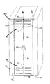
図13に示されるように、本発明の一実施形態では、テープヘッド10は、磁軸Mの第1の端部77に配置され、少なくとも1つの水平素子61(6つが示される)を含む第1の全体位置合わせパターン63と、磁軸Mの第2の端部79に配置され、少なくとも1つの水平素子61(6つが示される)を含む第2の全体位置合わせパターン65とを含む。水平素子61は位置合わせ素子31および書込み素子41と一体に形成され、各水平素子61は、磁軸Mに対する第2の固定された向きO2を有する。第2の固定された向きO2は、磁軸に垂直であることが好ましい。水平素子61は位置合わせ素子31および書込み素子41と一体に形成されるので、第2の固定された向きO2は、位置合わせ素子31および書込み素子41を参照して先に記載されたように、フォトリソグラフィによる精度で設定することができる。
【0063】
図14および図15を参照すると、媒体20が移送方向Tにテープヘッド10を横切って移送される際に、相対するエッジ21が第1の全体位置合わせパターン63に近接し、水平素子61aが、相対するエッジ21の外側で視認可能になる。同様に、相対するエッジ23が第2の全体位置合わせパターン65に近接し、水平素子61bが、相対するエッジ23の外側で視認可能になる。磁軸Mと移送方向Tとの間の全体的な視認による位置合わせは、水平素子(61a、61b)の一方あるいは両方が各相対するエッジ(21、23)に平行になるまで、ヘッド対媒体角θを調整する(50)ことにより得られる。
【0064】
図14では、水平素子(61a、61b)は、相対するエッジ(21、23)と破線67aおよび67bとの間の角度δによって示されるように、各相対するエッジ(21、23)に平行ではない。しかしながら、図15では、ヘッド対媒体角θを調整した後に(50)、水平素子(61a、61b)の両方が、破線67aおよび67bによって示されるように、相対するエッジ(21、23)に平行である。位置合わせが視認可能な位置合わせであるので、水平素子(61a、61b)と、相対するエッジ(21、23)との間の平行な関係は、全体的な関係である。好ましい向きβは移送方向Tとほぼ完全に垂直な位置合わせ状態にはなく、角度β´によって示されるように、書込み素子41が移送方向Tと概ね垂直な位置合わせ状態にある。
【0065】
水平素子61がミクロンあるいはサブミクロンの機構サイズを有する場合には、たとえば、マイクロスコープあるいはボアスコープのような光学的な拡大装置を用いて、相対するエッジ(21、23)を参照して水平素子61を観測することが必要とされる場合がある。全体的な視認による位置合わせは、機械による視認およびパターン認識を用いて全体的な視認による位置合わせを達成することを含む、手動、あるいは自動化された方法で達成することができる。ヘッド対媒体角θの調整50は、先に説明したように、テープヘッド10あるいはFRUを移動させることにより達成することができる。テープヘッド10の全体的な視認による位置合わせの後、テープヘッド10は、視認可能な水平素子を隠すために、上下に(矢印Vを参照)テープヘッド10を移動させることにより再配置することができる。上下方向への移動Vは、全体的な視認による位置合わせによって達成された相対するエッジ(21、23)に平行な関係を保持する。
【0066】
ここで図16のaおよび図16のbを参照すると、水平素子61および81が、第2の可変のピッチ(P3、P4)だけ離隔して配置される。第2の可変のピッチ(P3、P4)は、約20.0μm〜約200.0μmの範囲内にすることができる。好ましい実施形態では、第2の可変のピッチ(P3、P4)は互いに等しい(すなわちP3=P4)。しかしながら、第2の可変のピッチ(P3、P4)は、図16のbに示されるように等しい必要はなく、ピッチP3をピッチP4より大きくすることができる。水平素子61は、図16のaのように磁軸Mの両方の側に対をなすように配列することができるか、あるいは水平素子81は、図16のbのような磁軸Mに沿って対称に配列することができる。
【0067】
水平素子(61、81)は高さH1を有する。本発明の一実施形態では、高さH1は、1.0μm未満である(すなわち、H1<1.0μm)。別の実施形態では、高さH1は、1.0μm以上である(すなわち、H1≧1.0μm)。水平素子(61、81)のための高さH1は、全ての水平素子の場合に同じであることが好ましい。しかしながら、高さH1は、水平素子(61、81)の中で変更することができる。水平素子(61、81)は、全ての水平素子(61、81)の場合に同じであることができるか、水平素子(61、81)の中で変更することができる幅WHを有する。幅WHは、約50μm〜約1.0mm幅の範囲内にあることが好ましい。
【0068】
図14、図15、図16のaおよび図16のbに示されるように、本発明の一実施形態では、第1および第2の全体位置合わせパターン(63、65)は、水平素子61と一体に形成され、磁軸Mと同一直線上にある垂直素子71を備える。垂直素子71がいずれも、移送方向Tに対する磁軸Mの場所の正確な視認可能な指示子として機能するように、第1の全体位置合わせパターン63内の垂直素子71の少なくとも一部が相対するエッジ21の外側で視認可能であり、第2の全体位置合わせパターン65内の垂直素子71の少なくとも一部が相対するエッジ23の外側で視認可能である。磁軸Mと移送方向Tとの間の全体的な視認による位置合わせは、水平素子61の一方あるいは両方が各相対するエッジ(21、23)に平行であり、かつ垂直素子71の一方あるいは両方が各相対するエッジ(21、23)との好ましいエッジ向きφを有するまで、ヘッド対媒体角θを調整すること(50)により得られる。好ましいエッジ向きφは、相対するエッジ(21、23)に垂直であることが好ましい。
【0069】
図15に示されるように、本発明の別の実施形態では、相対するエッジ(21、23)の外側で視認することができる水平素子61は、テープヘッド10を視覚的に媒体20上の中央に配置するために用いられる。先に記載したように、水平素子61を用いて、テープヘッド10の全体的な視認による位置合わせを行った後、相対するエッジ(21、23)に対する平行な関係が保持されるように、テープヘッド10を上下に移動させることができ(V)、相対するエッジ21とテープヘッド10の上端との間の距離がおおむねD1になるように、かつ相対するエッジ23とテープヘッド10の下端との間の距離が概ねD2になるように、テープヘッド10を視覚的に媒体20上の中央に配置することができる。それゆえ、テープヘッド10が媒体20に対して対称的に中央に配置されることになる場合には、D1=D2である。一方、テープヘッド10が媒体20に対して対称ではない場合には、D1およびD2は、互いに概ね等しくならなくてもよく、D1およびD2の値は応用形態に依存するであろう。
【0070】
さらに、上記の実施形態が垂直素子71を含む場合には、垂直素子71を用いて、テープヘッド10の磁軸Mが確実に、各相対するエッジ(21、23)に対する好ましいエッジ向きφを有するようにすることができる。たとえば、好ましいエッジ向きφ=90°であり、水平素子(61a、61b)が相対するエッジ(21、23)に平行であるとき、テープヘッド10を上下に移動させ(V)、媒体20上の中央に配置することができる。水平素子61は、全体的な視覚による位置合わせ中に、相対するエッジ(21、23)の外側でもっぱら視認可能である必要がある。その後、テープヘッド10を上下に移動させ(V)、水平素子61を媒体20の背後に隠すことができる。
【0071】
テープヘッド10を媒体20上の中央に配置することの利点は、媒体20上に遷移部(33、43)を書き込む前に、媒体20に対する書込み素子41および位置合わせ素子31の近似的な位置がわかるように、テープヘッド10を最初に視覚的に中央に配置できることを含む。
【0072】
図16のaを参照すると、垂直素子71は、線幅WVおよび高さHVを有する。線幅WVは、約0.5μm〜約3.0μm幅にすることができる。高さHVは、約20.0μm〜約200.0μmにすることができる。本発明の一実施形態では、垂直素子71の線幅WVは、位置合わせ素子31の線幅W2以上である(図9および図10を参照)(すなわち、WV≧W2)。
【0073】
垂直素子71を用いることの1つの利点は、それらの素子が位置合わせ素子31および書込み素子41と一体に形成され、磁軸Mと同一直線上にあることである。結果として、移送方向Tに対する書込み素子の改善された全体的な位置合わせが可能となる。なぜなら、垂直素子71が、テープヘッド10と、媒体20の相対するエッジ(21、23)とに対して磁軸Mの場所のための正確な視認マーカとして機能するためである。それゆえ、本発明の全体的な視認による位置合わせは、テープヘッドの形状に依存せず、テープヘッドが製造された後にテープヘッド上に形成される不正確な視認可能な指示子より優れている。
【0074】
垂直素子71および水平素子61を個別に、あるいは組み合わせて用いて、テープヘッド10の全体的な視認による位置合わせを達成することができる。手動あるいは自動化された手段により、上記のような垂直素子71および/または水平素子61を用いて全体的な視認による位置合わせを実行することができる。
【0075】
本発明の別の実施形態では、テープヘッド10の全体的な位置合わせは、以下に記載されるように水平素子61を用いて達成される(図13、図14および図15を参照)。水平素子61は、磁軸Mのそれぞれ第1および第2の端部(77、79)に配置される第1および第2の全体位置合わせパターン(63、65)に含まれる。水平素子61は書込み素子41と一体に形成される。しかしながら、図13、図14、および図15に示されるような位置合わせ素子31は、全体的な視認による位置合わせのみが望まれているので、この実施形態には含まれない。移送方向Tに対する書込み素子41の全体的な視認による位置合わせは、先に記載されたのと同じようにして達成される。上記のような垂直素子71は、個別に、あるいは水平素子61と組み合わせて、全体的な視認による位置合わせを達成するために、この実施形態に含まれることができる。垂直素子71のための好ましいエッジ向きφは、相対するエッジ(21、23)に垂直である。図16のaおよび図16のbを参照して先に記載されたような寸法(幅、高さおよび長さ)は、上記の実施形態にも当てはまる。
【0076】
水平素子61および垂直素子71は、位置合わせ素子31および書込み素子41を参照して先に記載されたような書込み電流に応答して磁界を生成するように構成することができる。しかしながら、水平素子61によって媒体20上に書き込まれる任意の遷移部は、後続の書込み電流パルスによって入れ替えられる(すなわち、上書きされる)であろう。同様に、垂直素子71によって媒体20上に書き込まれる任意の遷移部は、水平素子61からの遷移部によって基本的には上書きされるであろう。典型的には、相対するエッジ(21、23)に近いテープヘッド10の部分は、相対するエッジ(21、23)において媒体が持ち上がるため、媒体20がテープヘッド10を横切って移送される際に、媒体20と接触しない。この持ち上がりの結果、水平素子61および垂直素子71からの磁界が著しく低減され、磁界強度が低すぎて媒体20上に遷移部を良好に書き込むことができないので、テープ上に書き込まれる遷移部が、劣悪に画定されるか、あるいはほとんど存在しないほど、媒体20はテープヘッド10から変動したある距離だけ離れて存在する。
【0077】
ここで記載されるように、位置合わせ素子31、水平素子61および81、垂直素子71は、テープヘッドの当業者に知られている技術、および書込み素子41および読取り素子51を形成するためのフォトリソグラフィを用いて形成することができる。テープヘッド10は、図3および図17に示されるようなフェライト−ガラス−フェライト積層体から形成することができ、テープヘッド10は2つのフェライト層11間に挟まれたガラス層13を備える。ガラス層13は、素子、すなわち書込み素子41、位置合わせ素子31、読取り素子51、水平素子(61、81)、および垂直素子71が一体に形成される平坦な表面を有することが好ましい。テープヘッド10は、一枚のフェライト−ガラス−フェライト材料から一括で形成することができ、その後、鋸等を用いてそのシートから各テープヘッド10を切り出すことができる。
【0078】
マイクロエレクトロニクス技術においてよく知られているフォトリソグラフィプロセスを用いて、素子のためのパターンを形成できるように、ガラス層13のための平坦な表面が望まれる。素子を形成する間隙は、空気、フォトレジスト、あるいはいくつかの他の非磁性材料から形成することができる。書込み素子41は、たとえば、ハーフシェブロンパターン、フルシェブロンパターン、ハーフダイヤモンドパターン、フルダイヤモンドパターンを含む形状を有することができる(それぞれ図3のa、図3のbおよび図3のcを参照されたい)がこれらに限定されない。書込み素子41のための形状は、ここに図示および記載される形状に限定されるものと解釈されるべきではなく、他の形状を用いることができ、応用形態、および書込み素子41によって書き込まれる遷移部を良好に読み取るための読取り変換器の能力が、書込み素子41の形状を決定する。ガラス層13に曲面を用いることができるが、曲面上に素子のための均一なパターンを形成することはさらに難しい。さらに、曲面上に均一なパターンを形成することは、平面上のパターンを形成するために必要とされるものより、複雑で、高価な装置を必要とする。本発明の素子のためのパターンを形成するために、従来のフォトリソグラフィ装置を用いることができる。
【0079】
本発明のテープヘッド10には、閉ループサーボヘッド、薄膜磁気抵抗ヘッド、薄膜磁気抵抗サーボ書込みヘッド等を用いることができる。たとえば、LTOのような応用形態の場合には、素子のための機構サイズは、ミクロンおよびサブミクロン範囲になるが、本発明の原理は、テープヘッドの変換器素子を媒体の移送方向と位置合わせすること、あるいはテープヘッド自体を媒体の移送方向に位置合わせすることが望まれる任意のテープヘッドに当てはまる。
【0080】
典型的なテープヘッド10を形成し、素子(31、41、51、61、71および81)のためのパターンを形成する方法は、2000年1月25日にBeck等に付与された「Batch Fabricated Servo Write Head Having Low Write-Gap Linewidth Variation」というタイトルの米国特許第6,018,444号に記載されており、その全体を参照により本明細書に援用する。
【0081】
本発明を、構造的と方法的特徴に関してある程度特定的な言葉で説明したが、本明細書に開示した手段は本発明を実施する好ましい形態を含むものであり、本発明はこれら図示し記載された特定の特徴に制限されないことを理解されたい。したがって、本発明は、均等の原則に従って適切に解釈される特許請求の範囲に記載された範囲内におけるいかなる形態または変更についても含むものである。
【0082】
本発明は、以下に要約される。
1.
テープヘッド(10)を横切って移送され、相対するエッジ(21、23)を有する媒体(20)の移送方向(T)に対して、前記テープヘッド(10)上に書込み素子(41)を正確に位置合わせするための装置であって、
前記書込み素子(41)と一体に形成される少なくとも1つの位置合わせ素子(31)を備え、前記書込み素子(41)および前記位置合わせ素子(31)はいずれも、前記テープヘッド(10)の磁軸(M)に対して第1の固定された向きを(O1)を有し、
前記書込み素子(41)および前記位置合わせ素子(31)は、前記テープヘッドに供給される書込み電流によって誘発される磁界を生成するように構成され、
前記書込み素子(41)が生成する前記磁界は、前記媒体(20)上に複数の書込み遷移部(43)を書込み、それにより前記媒体(20)上に書込みバンド(45)を画定し、
前記位置合わせ素子(31)が生成する前記磁界は、前記移送方向(T)に対して記録された向き(Δ)を有する複数の位置合わせ遷移部(33)を前記媒体(20)上に書込み、それにより前記媒体(20)上に位置合わせバンド(35)を画定し、
前記正確な位置合わせは、前記位置合わせバンド(35)内の前記位置合わせ遷移部(33)を観測し、前記位置合わせ遷移部(33)の前記記録された向き(Δ)が、前記書込み素子(41)が前記移送方向(T)に対して好ましい向き(β)を有することを示すまで、前記磁軸(M)と前記移送方向(T)との間のヘッド対媒体角(θ)を調整する(50)ことにより得られる、
ことを特徴とする装置。
2.
前記位置合わせ素子(31)は、前記位置合わせ遷移部(33)が前記書込み遷移部(43)と干渉せず、前記書込み遷移部(43)を上書きもせず、かつ他に使用するために予め指定されている前記媒体(20)上の領域(A)を占有しないように配置されることを特徴とする第1項に記載の装置。
3.
他に使用するために予め指定されている前記媒体(20)上の前記領域(A)はフォーマット仕様に準拠することを特徴とする第2項に記載の装置。
4.
前記書込み遷移部(43)は、前記媒体(20)上に予め記録されるサーボコードを含む第1項に記載の装置。
5.
前記好ましい向き(β)は、前記移送方向(T)に垂直であることを特徴とする第1項に記載の装置。
6.
前記ヘッド対媒体角(θ)は、前記好ましい向き(β)が前記移送方向(T)と垂直であるときに、90°であることを特徴とする第5項に記載の装置。
7.
前記位置合わせ素子(31)の前記第1の固定された方向(O1)は、前記位置合わせ素子(31)が前記磁軸(M)に沿って位置合わせされるように、前記磁軸(M)と同一直線上にあることを特徴とする第1項に記載の装置。
8.
前記位置合わせ素子(31)の前記第1の固定された向き(O1)は、前記磁軸(M)に平行(A1、A2)であり、前記位置合わせ素子(31)は、前記磁軸(M)からオフセットされた位置を有することを特徴とする第1項に記載の装置。
9.
前記位置合わせ遷移部(33)を観測するために、前記テープヘッド(10)と所定の関係で配置された個別の読取りヘッド(60)を備え、前記読取りヘッド(60)は、前記媒体(20)が前記読取りヘッド(60)を横切って移送される際に、前記位置合わせバンド(35)内に記録された前記位置合わせ遷移部(33)から第1の読取り信号(S1)を生成するように構成された第1の読取り素子(40)を備え、
前記ヘッド対媒体角(θ)は、前記第1の読取り信号(S1)が前記記録された向き(Δ)が前記移送方向(T)に対して好ましい位置合わせ状態を示す所定のシグネチャと一致し、かつ、前記所定のシグネチャが前記書込み素子(41)が前記移送方向(T)に対して好ましい向き(β)を有するまで調整される(50)、
ことを特徴とする第1項に記載の装置。
10.
前記読取りヘッド(60)はさらに、前記媒体(20)が前記読取りヘッド(60)を横切って移送される際に、近隣の位置合わせバンド(35)内に記録された前記位置合わせ遷移部(33)から第2の読取り信号(S2)を生成するように構成された第2の読取り素子(40)を備え、かつ、前記所定のシグネチャは、指定された許容範囲DT内にほぼ同時に生じる前記第1の読取り信号(S1)および前記第2の読取り信号(S2)を有することを特徴とする第9項に記載の装置。
11.
少なくとも1つの水平素子(61)を有し、前記磁軸(M)の第1の端部(77)に配置される第1の全体位置合わせパターン(63)を備え、
少なくとも1つの水平素子(61)を有し、前記磁軸(M)の第2の端部(79)に配置される第2の全体位置合わせパターン(65)を備え、
前記第1および前記第2の全体位置合わせパターン(63、65)の前記水平素子(61)は、前記書込み素子(41)および前記位置合わせ素子(31)と一体に形成され、前記各水平素子(61)は、前記磁軸(M)に対して第2の固定された向きO2を有し、
前記媒体(20)が前記テープヘッド(10)を横切って移送される際に、前記相対するエッジ(21、23)のうちの第1のエッジが前記第1の全体位置合わせパターン(63)に近接し、前記水平素子(61)が前記相対するエッジ(21、23)のうちの前記第1のエッジの外側で視認され、また前記相対するエッジ(21、23)のうちの第2のエッジが前記第2の全体位置合わせパターン(65)に近接し、その前記水平素子(61)が前記相対するエッジ(21、23)のうちの前記第2の端部の外側で視認され、
前記磁軸(M)と前記移送方向(T)との間の全体視認位置合わせは、前記水平素子(61)が前記第1のエッジおよび前記第2のエッジで構成される前記相対するエッジ(21、23)のうちの一方あるいは両方と平行になるまで、前記ヘッド対媒体角(θ)を調整することにより得られ、前記全体視認位置合わせの後に、前記テープヘッド(10)は、前記視認可能な水平素子(61)が隠れるように再配置される、
ことを特徴とする第1項に記載の装置。
12.
前記各相対するエッジ(21、23)の外側で視認可能な前記第1および前記第2の全体位置合わせパターン(63、65)内の前記水平素子(61)は、前記媒体(20)に対して前記テープヘッド(10)を視覚的に中央に配置するように、前記テープヘッド(10)を調整するために用いられることを特徴とする第11項に記載の装置。
13.
前記第1および前記第2の全体位置合わせパターン(63、65)は、
前記磁軸(M)と同一直線上にあり、前記水平素子(61)と一体に形成された垂直素子(71)を備え、
前記第1および前記第2の全体位置合わせパターン(63、65)内の前記垂直素子(71)の少なくとも一部は、両方の前記垂直素子(71)が、前記移送方向(T)に対する前記磁軸(M)の場所の正確な視認可能な指示子として機能するように前記各相対するエッジ(21、23)の外側で視認することができ、かつ、前記磁軸(M)と前記移送方向(T)との間の前記全体視認位置合わせは、前記垂直素子(71)の一方あるいは両方が、前記第1のエッジ(21)あるいは前記第2のエッジ(23)に対して好ましいエッジ向き(φ)を有するまで、前記ヘッド対媒体角(θ)を調整することにより得られる、
ことを特徴とする第11項に記載の装置。
14.
前記好ましいエッジ方向(φ)は、前記相対するエッジ(21、23)に垂直であることを特徴とする第13項に記載の装置。
15.
前記書込み素子(41)および前記位置合わせ素子(31)と一体に形成される少なくとも1つの読取り素子(51)をさらに備え、前記読取り素子(51)は、前記媒体(20)が前記移送方向(T)に前記テープヘッド(10)を横切って移送される際に、前記位置合わせ遷移部(33)が前記読取り素子(51)上を通過するように、前記位置合わせ素子(31)と位置合わせされ(A´)、
前記読取り素子(51)は、前記位置合わせ遷移部(33)に応答して読取り信号を生成するように構成され、
前記読取り信号は、前記読取り信号の大きさが、前記位置合わせ遷移部(33)が良好に書き込まれたことを示すか否かを判定するために解析される、
ことを特徴とする第1項に記載の装置。
16.
前記位置合わせ素子(31)に対する前記書込み電流は、前記読取り信号の大きさが前記位置合わせ遷移部(33)が良好に書き込まれたことを示さないときに、増加することを特徴とする第15項に記載の装置。
17.
前記位置合わせ素子(31)は、前記位置合わせ遷移部(33)が他に使用するためにあらかじめ指定されている前記媒体(20)上の領域(A)を占有するように配置されることを特徴とする第1項に記載の装置。
18.
前記媒体(20)は移送方向Dに個別のデータヘッド(70)を横切って移送され、前記データヘッド(70)は、前記データヘッド(70)の磁軸(M´)に沿って形成される複数のデータ素子(81)を備え、前記データ素子(81)はそれぞれ、前記位置合わせ遷移部(33)が前記データ素子(81)上を通過するのに応答して、データ信号を生成するように構成され、前記位置合わせ遷移部(33)は前記媒体(20)上に予め記録され、前記移送方向(D)に対して好ましい位置合わせ状態を有し、
前記データヘッド(70)と前記移送方向(T)との間の前記正確な位置合わせは、前記データ素子(81)のうちの少なくとも2つからの前記データ信号を解析し、前記データ信号が、前記データヘッド(70)が前記移送方向(D)に対して好ましい方位角を有することを示すシグネチャと一致するまで、前記磁軸(M´)と前記移送方向(D)との間のデータヘッド対媒体角(Ψ)を調整する(55)ことにより得られる、
ことを特徴とする第17項に記載の装置。
19.
前記データヘッド(70)はさらに、前記磁軸(M´)に沿って形成される少なくとも1つの書込み素子(91)を備え、前記書込み素子(91)および前記データ素子(81)はいずれも、前記データヘッド(70)が前記移送方向(D)に対して前記好ましい方位角を有するときに、前記移送方向(D)と位置合わせされることを特徴とする第18項に記載の装置。
20.
テープヘッド(10)を横切って移送され、相対するエッジ(21、23)を有する媒体(20)の移送方向(T)に対して、前記テープヘッド(10)の書込み素子(41)を全体的に視認により位置合わせするための装置であって、
前記テープヘッド(10)の磁軸(M)の第1の端部(77)に配置され、少なくとも1つの水平素子(61)を有する第1の全体位置合わせパターン(63)を備え、
前記磁軸(M)の第2の端部(79)に配置され、少なくとも1つの水平素子(61)を有する第2の全体位置合わせパターン(65)を備え、
前記第1および前記第2の全体位置合わせパターン(63、65)の前記水平素子(61)は前記書込み素子(41)と一体に形成され、前記各水平素子(61)は前記磁軸(M)に対して第2の固定された向き(O2)を有し、
前記書き込み素子(41)は、前記テープヘッド(10)に供給される書込み電流によって誘発される磁界を生成するように構成され、前記磁界は、前記媒体(20)上に複数の書込み遷移部(43)を書込み、それにより前記媒体(20)上に書込みバンド(45)を画定し、
前記媒体(20)が前記テープヘッド(10)を横切って移送される際に、前記相対するエッジ(21、23)のうちの第1のエッジが、前記第1の全体位置合わせパターン(63)に近接し、その前記水平素子(61)は前記相対するエッジ(21、23)のうちの前記第1のエッジの外側で視認可能であり、かつ、前記相対するエッジ(21、23)のうちの第2のエッジが、前記第2の全体位置合わせパターン(65)に近接し、その前記水平素子(61)は前記相対するエッジ(21、23)のうちの前記第2のエッジの外側で視認可能であり、
前記移送方向(T)に対する前記書込み素子(41)の前記全体視認位置合わせは、前記水平素子(61)の一方あるいは両方が前記相対するエッジ(21、23)のうちの前記各第1あるいは第2のエッジに平行になるまで、前記磁軸(M)と前記移送方向(T)との間のヘッド対媒体角(θ)を調整する(50)ことにより得られる、
ことを特徴とする装置。
21.
前記第1および前記第2の全体位置合わせパターン(63、65)はさらに、第2の可変のピッチ(P3、P4)だけ離隔して配置された複数の水平素子(61)を備えることを特徴とする第20項に記載の装置。
22.
前記各相対するエッジ(21、23)の外側で視認することができる前記第1および前記第2の全体位置合わせパターン(63、65)内の前記水平素子(61)は、前記媒体(20)に対して前記テープヘッド(10)を視覚的に中央に配置するように前記テープヘッド(10)を調整するために用いられることを特徴とする第20項記載の装置。
23.
前記第1および前記第2の全体位置合わせパターン(63、65)はさらに、
前記磁軸(M)と同一直線上にあり、前記水平素子(61)と一体に形成される垂直素子(71)を備え、
前記第1および前記第2の全体位置合わせパターン(63、65)内の前記垂直素子(71)の少なくとも一部は、双方の前記垂直素子(71)が前記移送方向(T)に対する前記磁軸(M)の場所の正確な視認可能な指示子として機能するように、それぞれの前記相対するエッジ(21、23)の外側で視認可能であり、
前記移送方向(T)に対する前記書込み素子(41)の前記全体視認位置合わせは、前記垂直素子(71)の一方あるいは両方が、前記各第1および第2のテープエッジ(21、23)に対して好ましいエッジ向き(φ)を有するまで、前記ヘッド対媒体角(θ)を調整することにより得られる、
ことを特徴とする第20項に記載の装置。
24.
前記好ましいエッジ向き(φ)は、前記相対するエッジ(21、23)に対して垂直であることを特徴とする第23項に記載の装置。
25.
データヘッド(70)を横切って移送される媒体(20)の移送方向(D)に対して前記データヘッド(70)を正確に位置合わせするために、前記データヘッド(70)の少なくとも1つのデータ素子(81)を用いるための装置であって、
前記移送方向(D)に対して好ましい位置合わせ(Δ)を有する位置合わせバンド(35)内の前記媒体(20)上に予め記録される複数の位置合わせ遷移部(33)を有し、
前記データ素子(81)は、前記媒体(20)が前記移送方向(D)に前記データヘッド(70)を横切って移送される際に、前記位置合わせ遷移部(33)が前記データ素子(81)上を通過するのに応答して、データ信号を生成するように構成され、
前記データヘッド(70)と前記移送方向(D)との間の方位角を調整する(55)ための方位角制御ユニットを備え、前記方位角制御ユニットは前記データ信号を受信し、前記データヘッド(70)に接続され、
前記正確な位置合わせは、前記データ信号を解析し、前記データ信号が、前記データヘッド(70)が前記移送方向(D)に対して好ましい方位角を有することを示すシグネチャと一致するまで、前記データヘッド(70)と前記移送方向(D)との間のデータヘッド対媒体角(Ψ)を調整することにより得られる、
ことを特徴とする装置。
26.
前記好ましい方位角は、前記移送方向(D)に垂直であることを特徴とする第25項に記載の装置。
27.
前記データ素子(81)は、前記データヘッド(70)に供給されるデータ電流に応答して磁界を生成するように構成され、前記磁界は、前記位置合わせ遷移部(33)の少なくとも一部を複数のデータ遷移部で上書きすることを特徴とする第25項に記載の装置。
【図面の簡単な説明】
【図1】 aは従来技術の視認可能な指示子を用いるテープヘッド位置合わせの位置合わせ前を表した図である。bはその位置合わせ後を表す図である。
【図2】 aはテープの縁を用いた従来技術によるテープヘッド位置合わせの位置合わせ前を表す図である。bはその位置合わせ後の図である。
【図3】 aないしcは、本発明による書込み素子の形状を表す図である。dは本発明による位置合わせ素子を含むテープヘッドの外形図である。
【図4】 本発明による、媒体上への位置合わせ遷移部および書込み遷移部の書込み位置の例を表す図である。
【図5】 本発明による第1の固定された向きを示す図である。
【図6】 本発明による好ましい向きを示す図である。
【図7】 本発明による位置合わせ前後の記録された向きを示す図である。
【図8】 本発明による位置合わせ前後の記録された向きを示す図である。
【図9】 本発明による位置合わせ素子および書込み素子の長さおよび線幅を示す図である。
【図10】 本発明による位置合わせ素子および書込み素子の長さおよび線幅を示す図である。
【図11】 a、bはそれぞれ本発明による互いに平行ではない辺を有するテープヘッドの位置合わせを示す図である。
【図12】 本発明による位置合わせ遷移部を観測するための読取りヘッドおよび読み取りヘッドで生成された位置合わせ遷移部に応答するデータ信号を表した図である。
【図13】 本発明による、全体の位置合わせのための水平素子および垂直素子を有するテープヘッドを示す図である。
【図14】 本発明による全体的な視認による位置合わせ前の垂直素子および水平素子を有するテープヘッドを示す図である。
【図15】 本発明による全体的な視認による位置合わせ後の垂直素子および水平素子を有するテープヘッドを示す図である。
【図16】 本発明による水平素子および垂直素子の長さ、幅、および高さを示す図である。
【図17】 本発明による位置合わせ素子と対をなす読取り素子が一体となったテープヘッドの平面図である。
【図18】 aは、本発明による、媒体に位置合わせ遷移部を書き込み、その後にその媒体を使用し、ヘッド対媒体角を調整することで媒体の移送方向にデータヘッドを正確に位置合わせするテープヘッドを表した図である。bは、さらにテープ進行方向に対し縦方向にテープヘッド位置を調整できるテープヘッドを表した図である。
【符号の説明】
10 テープヘッド
20 媒体
21、23 相対するエッジ
31 位置合わせ素子
33 位置合わせ遷移部
35 位置合わせバンド
40 読取り素子
41 書込み素子
43 書込み遷移部
45 書込みバンド
51 読取り素子
60 読取りヘッド
61 水平素子
63 第1の全体位置合わせパターン
65 第2の全体位置合わせパターン
70 データヘッド
71 垂直素子
77 第1の端部
79 第2の端部
81 データ素子(水平素子)
91 書込み素子[0001]
BACKGROUND OF THE INVENTION
The present invention generally relates to a tape head that includes at least one alignment element for accurately aligning the tape head with the transport direction of a medium transported across the tape head. More specifically, the present invention is formed integrally with the write element of the tape head, and the magnetic axis of the tape head is such that the write element can be accurately aligned with the transport direction of the medium being transported across the tape head. And a tape head including at least one alignment element.
[0002]
[Prior art]
Servo writer heads that write servo codes to one or more individual servo bands along the entire length of the tape in one pass are well known. The servo code is written on the tape by a writing element (magnetic transducer) formed on the servo writer head. The writing element has a predetermined pattern such as a chevron pattern. Servo band is separated by a certain pitchWaitThus, the area between adjacent servo bands is reserved for applications such as data storage, for example. Typically, servo codes on at least two servo bands of individual servo bands are used to generate a servo signal, which servo signal is one or more individual along the length of the tape. It is used to align the data elements on the read / write head to the correct position in order to read or write data to the data band. The data band is arranged in a region between servo bands. Servo codes are pre-recorded on the tape during tape manufacture and individual servo bands are placed at predetermined locations across the width of the tape. Those predetermined locations can be defined by the format specification for the tape. For example, the format specification determines the number of servo bands, the number of data bands, and their position relative to each other across the width of the tape.
[0003]
Because more data is stored in the same amount of physical space on the tape, better reference and location accuracy is required. In order to increase the amount of data stored, the write and read element features must be reduced to micron or sub-micron dimensions to increase the number of data bands that can be accommodated across the width of the tape. Don't be. To servo-write a tape, higher accuracy is required as the write and data element mechanism size decreases. When the servo code is written on the tape, the servo code is placed at the center of the pattern of write elements and must be as perpendicular as possible to the direction of tape movement in order to scan the tape in a straight line.
[0004]
Ideally, when the tape is transported over the servo writer head, the pattern for the write element should be accurately oriented relative to the direction of movement of the tape on the head. Typically, the orientation is perpendicular to the direction of tape movement. In most applications, the servo writer header is attached to a fixture or jig such as, for example, a field replaceable unit (hereinafter FRU). FRU is a servo writerHePlace the card in a fixed direction relative to the tape. The FRU can be designed such that the position of the servo writer head, FRU, or both are adjusted relative to the tape so that the servo writer head can be aligned with the tape and / or the direction of tape movement.
[0005]
Conventional methods that attempt to align the servo writer head include placing a visible indicator on the servo writer head. Typically, the visible indicator is arranged to approximate the location of the magnetic axis of the servo writer head. The servo writer head is aligned by adjusting the azimuth angle with respect to the tape until the visible indicator appears to be perpendicular to the direction of tape movement or to one or both of the tape edges. Is done. A method for forming a visible indicator includes marking a servo writer head with a tool to form a visible indicator. For example, a visually recognizable indicator can be formed using a notched (or notched) mark.
[0006]
FIG.ofa and FIG.ofReferring to b, the prior
[0007]
Prior attempts to align the servo writer head have also included using opposite sides of the servo writer head to align the servo writer head with the tape. This approach assumes that the opposing sides of the servo writer head are manufactured such that the opposing sides are parallel to each other and parallel and / or perpendicular to the magnetic axis of the servo writer head. However, in practice, the servo writer head may be cut using a saw blade or the like. As a result, the opposing sides will not be strictly parallel to each other. For example, the servo writer head will not have a rectangular shape, but a parallelogram shape.
[0008]
FIG.ofa and FIG.ofReferring to b, the prior
[0009]
In the application form of the servo writer head, an error occurs in the azimuth angle of the servo code written on the tape during manufacture as a result of the above-mentioned alignment problem. For example, in the linear tape open (LTO) format, servo codes are written on the tape in five bands. The alignment of the data head to the tape is accomplished using band-to-band alignment between adjacent servo bands. Using the servo codes in the adjacent servo bands, a position signal that is an average value of the servo codes in the adjacent bands is derived. When the servo writer head write transducer is not aligned in the transport direction, one servo code in one adjacent servo band will be written on the tape prior to a servo code in another adjacent servo band. (Ie, when viewed on tape, one servo band will appear to be written before the other servo band). As a result, servo codes in adjacent servo bands have inherent azimuth errors that cause skew (interband skew) in the average value used to derive the position signal. A band ID failure occurs due to the band-to-band skew, or it takes a long time to position the data head due to the band-to-band skew.
[0010]
As described above, reducing the mechanism size of the transducer requires higher accuracy than the alignment accuracy that can be achieved using the prior art described above. For example, the same-surface servo (same-surface-) where the servo code is pre-recorded on the tape before the data is written to or read from the tape.servoFor application applications, it is important that the servo code is accurately aligned with the tape so that the servo band is parallel to the tape movement direction and the servo code is aligned perpendicular to the tape movement direction. It is. If the servo code is not accurately aligned to the tape, the servo code will occupy and / or interfere with data in the adjacent data band. Since servo codes are pre-recorded on the tape before the data is written to the tape, the resulting misalignment cannot be corrected after the tape is manufactured. Therefore, it is essential to perform accurate alignment during manufacturing.
[0011]
[Problems to be solved by the invention]
Therefore, it is necessary to accurately align the write element on the tape head with the transport direction of the tape being transported across the tape head. In addition, it is necessary to accurately align the write elements on the tape head with the transport direction of the tape being transported across the tape head so that band-to-band skew is significantly reduced or eliminated. Also, it is necessary to align the writing element with the tape transport direction as a whole without the opposing sides of the tape head being parallel or physically marking the tape head. .
[0012]
[Means for Solving the Problems]
In general, the present invention is embodied in a tape head that includes at least one write element and one or more alignment elements formed integrally with the write element. The alignment element and the writing element have a fixed orientation with respect to the magnetic axis of the tape head. Both the write element and the alignment element function to generate a magnetic field induced by a write current supplied to the tape head. The magnetic field from the write element writes a plurality of write transitions in a write band on the media that is transported across the tape head in the transport direction. Similarly, the magnetic field from each alignment element writes a plurality of alignment transitions to the alignment band on the medium. Accurate alignment of the write element with respect to the transport direction is observed by observing the alignment transitions within the individual alignment bands, after which the observed alignment transition has been aligned with the transfer element. Can be achieved by adjusting the head-to-medium angle between the magnetic axis and the transport direction.
[0013]
In one embodiment of the invention, the tape head includes a single alignment element formed integrally with the write element, both the write element and the alignment element having a fixed orientation with respect to the magnetic axis. A magnetic field from the alignment element writes a plurality of alignment transitions in one alignment band on the medium. Accurate alignment of the write element with respect to the transport direction is observed by the alignment transition within that one alignment band, after which the observed alignment transition is aligned with the write element in the transport direction. This can be achieved by adjusting the head-to-medium angle between the magnetic axis and the transport direction.
[0014]
Since the alignment of the writing element relative to the transport direction is independent of the shape of the tape head, the above-mentioned misalignment caused by the sides of the tape heads not parallel to each other is solved by the present invention. Therefore, the sides of the tape head need not be parallel to each other. Further, since the alignment of the writing element with respect to the transfer direction is determined by observing the alignment transition portion on the medium, the alignment failure that is considered to be caused by the fact that the visible indicator is not aligned with the magnetic axis. Is also solved by the present invention. Therefore, it is substantially unnecessary to provide an incompletely visible indicator on the tape.
[0015]
Furthermore, the need for higher alignment accuracy and better reference and position accuracy is solved by the alignment element of the present invention. Since both the write element and the alignment element have a fixed direction with respect to the magnetic axis, the direction of the write element with respect to the transport direction can be determined from the direction of the alignment transition portion written on the medium.
[0016]
Problems associated with band-to-band skew can be eliminated or significantly reduced by the alignment elements of the present invention because the band-to-band skew is caused by misalignment of the write element with respect to the transport direction. As a result, the azimuth error between servo bands can be ignored when the writing element is aligned with the transport direction as indicated by the alignment transition written on the media.
[0017]
In another embodiment, the present invention may comprise horizontal and / or vertical elements that are integrally formed with the writing element. The horizontal elements are parallel to each other and perpendicular to the magnetic axis. The overall visual alignment of the tape head to the opposite edges of the media adjusts the head-to-media angle until the horizontal element appears parallel to either or both of the opposite edges of the media. This can be achieved. The overall visual alignment of the tape head with respect to the transport direction can be achieved by adjusting the head-to-media angle until the vertical element appears perpendicular to the transport direction or to one or both of the opposite edges. In addition, the vertical element is collinear with the magnetic axis and accurately indicates the location of the magnetic axis. The horizontal and vertical elements can be used individually or in combination to achieve overall visual alignment.
[0018]
The above problems associated with using a visible indicator are solved by the vertical element of the present invention. First, the vertical element is integrally formed with the write element and is collinear with the magnetic axis so that the vertical element provides a visually accurate indication of the location of the magnetic axis. Therefore, unlike prior art visible indicators, there is no need to guess or approximate the location of the magnetic axis after the tape head has been manufactured. Second, since the vertical elements are collinear with the magnetic axis, they are also parallel to the magnetic axis. As a result, if the vertical element is visually perpendicular to the transport direction or to one or both of the opposing edges, the magnetic axis is aligned generally perpendicular to the transport direction. Yes. Similarly, since the horizontal element is perpendicular to the magnetic axis, if the horizontal element is visually parallel to the opposite edge or transport direction, the magnetic axis is also aligned generally perpendicular to the transport direction. Yes.
[0019]
Furthermore, the tape head sides are parallel to each other because the overall alignment of the magnetic axes relative to the opposing tape edges and / or transport direction is independent of the shape of the tape head or the lack of parallel sides in the tape head. If not, the above problems are substantially meaningless with the horizontal and vertical elements of the present invention.
[0020]
In yet another embodiment of the invention, alignment transitions generated by alignment elements are used to achieve alignment of the tape head with respect to the media transport direction. A signal is derived from the alignment transition and is used to adjust the azimuth of the tape head relative to the media transport direction. The alignment transition can occupy a pre-designated area on the media for other use, and the alignment transition can then be overwritten by the tape head.
[0021]
Therefore, the requirement to align the tape head that reads and / or writes data to the tape with the tape transport direction is handled by the alignment element of the present invention. For example, during the manufacture of a tape that will be used to store data, a tape transition that includes alignment elements can be used to write alignment transitions on the tape. After manufacture, the tape can be transported across a data head that is configured to read and / or write data. The data head can include a transducer that reads the alignment transition, processes the signal therefrom, and uses it to align the data head so that the data head is aligned with the tape transport direction. The corner can be adjusted. The alignment transition can be permanently written to the tape, or can be overwritten by the data head thereafter.
[0022]
DETAILED DESCRIPTION OF THE INVENTION
Other aspects and advantages of the present invention will become apparent from the following detailed description, taken in conjunction with the accompanying drawings, illustrating by way of example the principles of the invention.
[0023]
In the following detailed description and in the several drawings, like elements are identified with like reference numerals.
[0024]
As shown in the drawings for purposes of illustration, the present invention is embodied in an apparatus for accurately aligning at least one write element of a tape head with the transport direction of a medium transported across the tape head. . The tape head includes at least one alignment element. The alignment element is formed integrally with the write element, and both the alignment element and the write element have a first fixed orientation with respect to the magnetic axis of the tape head. Further, the alignment elements can be spaced apart from the alignment elements proximate to the first variable pitch. The write element and alignment element generate a magnetic field induced by a write current supplied to the tape head. The magnetic field from the write element writes a plurality of write transitions on the medium. The written transition defines a write band on the medium. Similarly, the magnetic field from the alignment element writes a plurality of alignment transitions on the medium, thereby defining an alignment band on the medium. The alignment transition has a recorded orientation relative to the transport direction. The alignment element can be arranged relative to the writing element such that the alignment transition written on the medium does not interfere with the written transition and does not overwrite the written transition. Furthermore, the alignment transition unit can be arranged on the medium so as not to occupy an area on the medium that is designated in advance for other use. Accurate alignment of the writing element with respect to the transport direction is achieved by observing the alignment transition within the alignment band and confirming that the recorded orientation of the alignment transition has a preferred orientation with respect to the transport direction. Until shown, it is obtained by adjusting the head-to-medium angle between the magnetic axis of the tape head and the media transport direction.
[0025]
Reference is now made to FIGS. 3, 4, 5, and 6, in which the
[0026]
In FIG. 4, the magnetic field from the
[0027]
Applications for area A include conforming to a format specification for data storage on magnetic tape. For example, the format specifications can include Linear Tape Open Format (LTO), ULTRIUM® format, TRAVAN® format, and MAGSTAR® MP3570 format. In a format specification for a typical high density tape storage application, region A can include multiple data bands. Each data band includes data that is written to or read from the data band using a data head. In the application form of the servo writer head in which the
[0028]
In one embodiment of the present invention, the written
[0029]
First fixed orientation O1Can be collinear with the magnetic axis M so that the
[0030]
Here, FIG. 5, FIG. 6, FIG.ofa, FIG.ofb, FIG.ofa, FIG.ofb is referred to, in which the medium 20 is transported across the
[0031]
In one embodiment of the invention, the preferred orientation β is perpendicular to the transport direction T and the head to media angle θ2Is 90 °. First fixed orientation O1Is collinear with the magnetic axis M, so the head-to-medium angle θ2Is 90 °, the preferred orientation β is also 90 °. Also, the head-to-medium angle θ2Is 90 °, the recorded orientation Δ2Is also 90 °. However, the present invention should not be construed as limited to the angles shown and described herein. Preferred orientation β, recorded orientation Δ2, And the head-to-medium angle θ can be other than 90 °. Furthermore, the angles need not be the same as each other. For example, when the head-to-medium angle θ is 90 °, the recorded orientation Δ2Can be 45 ° and the preferred orientation β can be 60 °. Preferred orientation β, recorded orientation Δ2And the actual relationship between the head to media angle θ will depend on the application.
[0032]
In another embodiment of the present invention, FIGS.ofb, the first fixed orientation O so that the
[0033]
6 and 8ofReferring to b, in yet another embodiment of the present invention, the parallel axis A of FIG.1And A2As shown by the first fixed orientation O1Is parallel to the magnetic axis M.Same axis in parallel
[0034]
9 and 10, the
[0035]
The
[0036]
In one embodiment of the present invention, the
[0037]
The
[0038]
The advantage over using photolithography to form the
[0039]
Therefore, FIG.ofa and FIG.ofIn b, the
[0040]
Furthermore, the alignment between the magnetic axis M and the transfer direction T isIs determined by observing the recorded orientation Δ of the alignment transition unit 33.Even if the
[0041]
In one embodiment of the present invention, the recorded orientation Δ of the
[0042]
In another embodiment of the present invention, as shown in FIG. 12, the
[0043]
In yet another embodiment of the present invention, the
[0044]
Ideally, when the alignment transitions 33 are collinear with each other and the recorded orientation Δ has a preferred alignment state (Δ = 90 °) with the transport direction T as indicated by the axis C, Peak amplitude PA1And PA2Will occur approximately synchronously as shown in FIG. However, the first and second electrical signals (S1And S2) Peak amplitude PA1And PA2Is the allowable range DTCan occur within an acceptable time window as indicated by.
[0045]
On the other hand, when the
[0046]
The preferred alignment is perpendicular to the transport direction T (ie, the recorded orientation Δ = 90 ° in FIG. 12), but the preferred alignment need not be 90 ° with respect to the transport direction T. As noted above, other angles for the recorded orientation Δ can also satisfy the preferred alignment conditions. Furthermore, those skilled in the art will appreciate that the
[0047]
Referring now to FIG. 17, the
[0048]
Therefore, the effectiveness of the written
[0049]
In the above embodiment, the
[0050]
Further, in contrast to the above embodiment where the
[0051]
Here, FIG.ofReferring to a, the medium 20 has an
[0052]
Here, FIG.ofReferring to b, FIG.ofThe medium a is then transported across the data head 70 in the transport direction D. The transfer direction D is shown in FIG.ofAs shown in b, it can be left to right or vice versa. In response to the
[0053]
Accurate alignment between the data heads 70 depends on the data signal S1And S2Adjusts the data head-to-medium angle Ψ between the magnetic axis M ′ and the transport direction D until it coincides with a signature indicating that the
[0054]
The data head 70 can include at least one write element (not shown) formed along the magnetic axis M ′. When the
[0055]
Using the method described above with reference to FIG. 12, the data signal (S1And S2) And the azimuth can be adjusted until the signatures match (55). Once the adjustment of the azimuth is completed, the
[0056]
The principle of the present invention is that the data headIn the directionIt can also be applied to align. For example, the data head can be a component in a media drive that is used to store and retrieve data from the media. The media drive can be connected to, for example, a computer or a network. The alignment of the data head with respect to the medium is achieved using the
[0057]
Therefore, FIG.ofIn another embodiment of the present invention, also shown in a, the
[0058]
FIG.ofIn b, the medium 20 has a
[0059]
The exact alignment between the
[0060]
Furthermore, the data signal (S1And S2) Individually or in combination, the data head 70 in the transverse direction Z ′ is moved in the transport direction D, the
[0061]
FIG.ofIn the embodiment described above with reference to b, the data signal (S1And S2) Can be processed using a CPU / DSP as described above with reference to FIG. Similarly, adjustment and transverse direction for data head vs. media angle ΨDe to ZThe movement of the
[0062]
As shown in FIG. 13, in one embodiment of the present invention, the
[0063]
Referring to FIGS. 14 and 15, when the medium 20 is transported across the
[0064]
In FIG. 14, the horizontal elements (61a, 61b) are not parallel to each opposing edge (21, 23), as indicated by the angle δ between the opposing edges (21, 23) and the dashed
[0065]
When the
[0066]
Here, FIG.ofa and FIG.ofReferring to b, the
[0067]
Horizontal elements (61, 81) are at height H1Have In one embodiment of the present invention, the height H1Is less than 1.0 μm (ie, H1<1.0 μm). In another embodiment, the height H1Is 1.0 μm or more (ie, H1≧ 1.0 μm). Height H for horizontal elements (61, 81)1Is preferably the same for all horizontal elements. However, the height H1Can be changed in the horizontal elements (61, 81). The horizontal elements (61, 81) can be the same for all horizontal elements (61, 81) or can be changed within the horizontal elements (61, 81).HHave Width WHIs preferably in the range of about 50 μm to about 1.0 mm wide.
[0068]
14, 15 and 16ofa and FIG.ofAs shown in b, in one embodiment of the present invention, the first and second overall alignment patterns (63, 65) are formed integrally with the
[0069]
As shown in FIG. 15, in another embodiment of the present invention, the
[0070]
Further, when the above embodiment includes the
[0071]
The advantage of centering the
[0072]
FIG.ofReferring to a, the
[0073]
One advantage of using the
[0074]
The
[0075]
In another embodiment of the present invention, the overall alignment of the
[0076]
The
[0077]
As described herein,
[0078]
A flat surface for the
[0079]
The
[0080]
The method of forming a
[0081]
Although the present invention has been described in certain terms with regard to structural and methodological features, the means disclosed herein include preferred forms of practicing the invention, and the invention is illustrated and described. It should be understood that the invention is not limited to specific features. Accordingly, the present invention includes any forms or modifications within the scope of the claims as appropriately interpreted in accordance with the principle of equality.
[0082]
The present invention is summarized below.
1.
The writing element (41) is accurately placed on the tape head (10) with respect to the transport direction (T) of the medium (20) transported across the tape head (10) and having opposite edges (21, 23). A device for aligning with
At least one alignment element (31) formed integrally with the write element (41) is provided, and both the write element (41) and the alignment element (31) are magnetic elements of the tape head (10). The first fixed orientation relative to the axis (M) is (O1)
The write element (41) and the alignment element (31) are configured to generate a magnetic field induced by a write current supplied to the tape head;
The magnetic field generated by the write element (41) writes a plurality of write transitions (43) on the medium (20), thereby defining a write band (45) on the medium (20);
The magnetic field generated by the alignment element (31) writes a plurality of alignment transitions (33) on the medium (20) having a recorded orientation (Δ) relative to the transport direction (T). Thereby defining an alignment band (35) on the medium (20);
The accurate alignment is performed by observing the alignment transition section (33) in the alignment band (35), and the recorded orientation (Δ) of the alignment transition section (33) is determined by the writing element. The head-to-medium angle (θ) between the magnetic axis (M) and the transfer direction (T) until (41) indicates that it has a preferred orientation (β) with respect to the transfer direction (T). Obtained by adjusting (50),
A device characterized by that.
2.
The alignment element (31) is pre-configured so that the alignment transition (33) does not interfere with the write transition (43), does not overwrite the write transition (43), and is used for other purposes. 2. The apparatus according to
3.
The apparatus according to
4).
The write transition unit (43) includes a servo code recorded in advance on the medium (20).First1TermThe device described in 1.
5.
The apparatus according to
6).
The apparatus according to claim 5, wherein the head-to-medium angle (θ) is 90 ° when the preferred orientation (β) is perpendicular to the transport direction (T).
7).
The first fixed direction (O1) Is collinear with the magnetic axis (M) so that the alignment element (31) is aligned along the magnetic axis (M). apparatus.
8).
The first fixed orientation (O1) Is parallel to the magnetic axis (M) (A1, A2And the alignment element (31) has a position offset from the magnetic axis (M).
9.
In order to observe the alignment transition (33), it comprises an individual read head (60) arranged in a predetermined relationship with the tape head (10), the read head (60) comprising the medium (20). ) Is transported across the read head (60), the first read signal (S) from the alignment transition (33) recorded in the alignment band (35).1) Comprises a first read element (40) configured to generate
The head-to-medium angle (θ) is determined by the first read signal (S1) Coincides with a predetermined signature in which the recorded orientation (Δ) indicates a preferred alignment state with respect to the transport direction (T), and the predetermined signature indicates that the write element (41) is in the transport direction. Adjusted (50) until it has a preferred orientation (β) relative to (T),
2. The apparatus according to
10.
The read head (60) further includes the alignment transition (33) recorded in a neighboring alignment band (35) as the medium (20) is transported across the read head (60). ) To the second read signal (S2), And the predetermined signature has a specified tolerance DTIn the first read signal (S1) And the second read signal (
11.
A first overall alignment pattern (63) having at least one horizontal element (61) and disposed at a first end (77) of the magnetic axis (M);
A second global alignment pattern (65) having at least one horizontal element (61) and disposed at a second end (79) of the magnetic axis (M);
The horizontal elements (61) of the first and second overall alignment patterns (63, 65) are formed integrally with the writing elements (41) and the alignment elements (31), and the horizontal elements (61) is a second fixed orientation O with respect to the magnetic axis (M).2Have
When the medium (20) is transported across the tape head (10), a first edge of the opposing edges (21, 23) becomes the first overall alignment pattern (63). Close, the horizontal element (61) is visible outside the first edge of the opposing edges (21, 23) and the second edge of the opposing edges (21, 23) Is close to the second overall alignment pattern (65), and the horizontal element (61) is visible outside the second end of the opposing edges (21, 23),
In the overall visual alignment between the magnetic axis (M) and the transfer direction (T), the horizontal elements (61) are the opposite edges (the opposite edges (the second edge)). 21, 23) until it is parallel to one or both of the head angle and the medium angle (θ), and after the overall visual alignment, the tape head (10) Repositioned to hide possible horizontal elements (61),
2. The apparatus according to
12
The horizontal elements (61) in the first and second overall alignment patterns (63, 65) that are visible on the outside of the opposing edges (21, 23) are in relation to the medium (20). 12. The apparatus of
13.
The first and second overall alignment patterns (63, 65) are:
A vertical element (71) which is collinear with the magnetic axis (M) and formed integrally with the horizontal element (61);
At least some of the vertical elements (71) in the first and second overall alignment patterns (63, 65) are such that both of the vertical elements (71) have the magnetic field with respect to the transport direction (T). It can be seen outside the respective opposing edges (21, 23) so as to function as an accurately visible indicator of the location of the axis (M), and the magnetic axis (M) and the transfer direction (T), the one or both of the vertical elements (71) has a preferable edge orientation with respect to the first edge (21) or the second edge (23). obtained by adjusting the head-to-medium angle (θ) until it has φ),
The apparatus according to
14
14. Apparatus according to
15.
The reading element (51) further includes at least one reading element (51) formed integrally with the writing element (41) and the alignment element (31), and the reading element (51) has the medium (20) in the transport direction ( T) is aligned with the alignment element (31) so that the alignment transition (33) passes over the read element (51) when transported across the tape head (10). (A '),
The read element (51) is configured to generate a read signal in response to the alignment transition (33);
The read signal is analyzed to determine whether the magnitude of the read signal indicates that the alignment transition (33) has been successfully written.
2. The apparatus according to
16.
The write current to the alignment element (31) increases when the magnitude of the read signal does not indicate that the alignment transition (33) has been successfully written. The device according to item.
17.
The alignment element (31) is arranged to occupy the area (A) on the medium (20) designated in advance for other use by the alignment transition unit (33). The apparatus of
18.
The medium (20) is transported across individual data heads (70) in the transport direction D, the data head (70) being formed along the magnetic axis (M ') of the data head (70). A plurality of data elements (81), each of the data elements (81) generating a data signal in response to the alignment transition (33) passing over the data element (81); The alignment transition part (33) is pre-recorded on the medium (20) and has a preferable alignment state with respect to the transfer direction (D),
The exact alignment between the data head (70) and the transport direction (T) is to analyze the data signal from at least two of the data elements (81), the data signal being Data head between the magnetic axis (M ′) and the transfer direction (D) until the data head (70) coincides with a signature indicating that it has a preferred azimuth angle with respect to the transfer direction (D) Obtained by adjusting (55) the angle to medium (Ψ),
Item 18. The device according to Item 17,
19.
The data head (70) further includes at least one write element (91) formed along the magnetic axis (M ′), and the write element (91) and the data element (81) are both 19. Apparatus according to claim 18, characterized in that the data head (70) is aligned with the transport direction (D) when having the preferred azimuth angle with respect to the transport direction (D).
20.
With respect to the transport direction (T) of the medium (20) transported across the tape head (10) and having opposite edges (21, 23), the writing element (41) of the tape head (10) is totally It is a device for aligning by visual recognition,
A first overall alignment pattern (63) disposed at a first end (77) of the magnetic axis (M) of the tape head (10) and having at least one horizontal element (61);
A second overall alignment pattern (65) disposed at the second end (79) of the magnetic axis (M) and having at least one horizontal element (61);
The horizontal elements (61) of the first and second overall alignment patterns (63, 65) are formed integrally with the write element (41), and each horizontal element (61) is formed with the magnetic axis (M). ) In a second fixed orientation (O2)
The write element (41) is configured to generate a magnetic field induced by a write current supplied to the tape head (10), the magnetic field on the medium (20) having a plurality of write transitions ( 43), thereby defining a write band (45) on the medium (20),
When the medium (20) is transported across the tape head (10), the first of the opposing edges (21, 23) is the first global alignment pattern (63). The horizontal element (61) is visible outside the first edge of the opposed edges (21, 23) and of the opposed edges (21, 23) A second edge of the horizontal alignment pattern (65) close to the second overall alignment pattern (65), and the horizontal element (61) is outside the second edge of the opposing edges (21, 23). Visible,
The overall visual alignment of the writing element (41) with respect to the transfer direction (T) is determined by the first or the second of the opposing edges (21, 23) of one or both of the horizontal elements (61). Obtained by adjusting (50) the head-to-medium angle (θ) between the magnetic axis (M) and the transfer direction (T) until it is parallel to the edge of 2.
A device characterized by that.
21.
The first and second overall alignment patterns (63, 65) further include a second variable pitch (PThree, PFourThe device according to
22.
The horizontal elements (61) in the first and second overall alignment patterns (63, 65) that can be seen outside the respective opposing edges (21, 23) are the media (20). 21. The apparatus according to
23.
The first and second overall alignment patterns (63, 65) further include
A vertical element (71) which is collinear with the magnetic axis (M) and formed integrally with the horizontal element (61);
At least some of the vertical elements (71) in the first and second overall alignment patterns (63, 65) are such that both the vertical elements (71) are in the magnetic axis with respect to the transfer direction (T). Visible on the outside of each said opposite edge (21, 23) so as to function as an accurately visible indicator of the location of (M),
The overall visual alignment of the writing element (41) relative to the transport direction (T) is such that one or both of the vertical elements (71) are relative to the first and second tape edges (21, 23). Obtained by adjusting the head-to-medium angle (θ) until it has a preferred edge orientation (φ),
24.
24. Device according to
25.
In order to accurately align the data head (70) with respect to the transport direction (D) of the medium (20) transported across the data head (70), at least one data of the data head (70) An apparatus for using the element (81),
A plurality of alignment transitions (33) pre-recorded on the medium (20) in an alignment band (35) having a preferred alignment (Δ) relative to the transport direction (D);
When the medium (20) is transferred across the data head (70) in the transfer direction (D), the data transition element (81) is moved by the alignment transition (33) to the data element (81). ) Configured to generate a data signal in response to passing over,
An azimuth angle control unit for adjusting (55) an azimuth angle between the data head (70) and the transfer direction (D), the azimuth angle control unit receiving the data signal, and the data head Connected to (70),
The exact alignment analyzes the data signal until the data signal matches a signature indicating that the data head (70) has a preferred azimuth with respect to the transport direction (D). Obtained by adjusting the data head to medium angle (Ψ) between the data head (70) and the transport direction (D),
A device characterized by that.
26.
26. Apparatus according to item 25, characterized in that the preferred azimuth angle is perpendicular to the transport direction (D).
27.
The data element (81) is configured to generate a magnetic field in response to a data current supplied to the data head (70), and the magnetic field forms at least a part of the alignment transition (33). 26. The apparatus according to item 25, wherein the data is overwritten by a plurality of data transition units.
[Brief description of the drawings]
BRIEF DESCRIPTION OF DRAWINGS FIG. 1 is a diagram illustrating a position before alignment of a tape head using a visually recognizable indicator in the prior art. b is a diagram illustrating the position after the alignment.
FIG. 2A is a diagram showing a state before alignment of a tape head alignment according to a conventional technique using an edge of a tape. b is a view after the alignment.
FIGS. 3a to 3c are diagrams showing the shape of a writing element according to the present invention. FIGS. d is an external view of a tape head including an alignment element according to the present invention.
FIG. 4 is a diagram illustrating an example of write positions of an alignment transition unit and a write transition unit on a medium according to the present invention.
FIG. 5 shows a first fixed orientation according to the invention.
FIG. 6 shows a preferred orientation according to the present invention.
FIG. 7 is a diagram showing recorded orientations before and after alignment according to the present invention.
FIG. 8 is a diagram showing recorded orientations before and after alignment according to the present invention.
FIG. 9 is a diagram showing the length and line width of an alignment element and a writing element according to the present invention.
FIG. 10 is a diagram showing the length and line width of an alignment element and a writing element according to the present invention.
FIGS. 11a and 11b are diagrams showing alignment of a tape head having sides that are not parallel to each other according to the present invention. FIGS.
FIG. 12 is a diagram illustrating a read head for observing an alignment transition according to the present invention and a data signal in response to the alignment transition generated by the read head.
FIG. 13 shows a tape head with horizontal and vertical elements for overall alignment according to the present invention.
FIG. 14 shows a tape head having vertical and horizontal elements before alignment by overall viewing according to the present invention.
FIG. 15 shows a tape head having vertical and horizontal elements after alignment by overall viewing according to the present invention.
FIG. 16 shows the length, width and height of horizontal and vertical elements according to the present invention.
FIG. 17 is a plan view of a tape head in which a reading element paired with an alignment element according to the present invention is integrated;
FIG. 18a accurately aligns a data head in the direction of media transport by writing an alignment transition to the media and then using the media and adjusting the head-to-medium angle according to the present invention. It is a figure showing a tape head. b is a view showing a tape head capable of further adjusting the tape head position in the longitudinal direction with respect to the tape traveling direction.
[Explanation of symbols]
10 Tape head
20 medium
21, 23 Opposite edges
31 Alignment element
33 Alignment transition part
35 alignment band
40 Reading element
41 Writing element
43 Write transition part
45 writing band
51 Reading element
60 read head
61 Horizontal element
63 First overall alignment pattern
65 Second overall alignment pattern
70 Data head
71 Vertical element
77 First end
79 Second end
81 Data element (horizontal element)
91 Writing element
Claims (22)
前記テープヘッドを前記媒体の移送方向に対して位置決めする際の基準として定められる位置決め基準線に対し、前記位置合わせ素子はその長手方向が前記位置決め基準線と平行となるように、前記書込み素子はその長手方向が前記位置決め基準線に対して所定の傾斜角度を有するように、それぞれ配列され、
前記書込み素子および前記位置合わせ素子は、前記テープヘッドに供給される書込み電流によって誘発される磁界を生成するように構成され、
前記書込み素子が生成する前記磁界は、前記媒体上に複数の書込み遷移部を書込み、それにより前記媒体上に書込みバンドを画定し、
前記位置合わせ素子が生成する前記磁界は、前記移送方向に対して記録された向きを有する複数の前記位置合わせ遷移部を前記媒体上に書込み、それにより前記媒体上に位置合わせバンドを画定し、
前記位置合わせバンド内の前記位置合わせ遷移部は、前記位置合わせ遷移部を観測して前記位置合わせ遷移部の前記記録された向きを求め、前記位置決め基準線が前記媒体の移送方向に対して好ましい向きを有することを前記位置合わせ遷移部の前記記録された向きが示すまで、前記位置決め基準線と前記移送方向との間の角度を調整することを可能とするように構成されることを特徴とする装置。An alignment transition for confirming whether or not a writing element provided on the tape head is accurately aligned with respect to a transfer direction of a medium transferred across the tape head and having an opposing edge; An apparatus for enabling visual alignment of a write element of a tape head, wherein at least one alignment element recordable on a medium is formed integrally with the write element ,
The writing element is arranged so that the longitudinal direction of the alignment element is parallel to the positioning reference line with respect to a positioning reference line determined as a reference for positioning the tape head with respect to the transport direction of the medium. Each of the longitudinal directions is arranged so as to have a predetermined inclination angle with respect to the positioning reference line,
The write element and the alignment element are configured to generate a magnetic field induced by a write current supplied to the tape head;
The magnetic field generated by the write element writes a plurality of write transitions on the medium, thereby defining a write band on the medium;
The magnetic field generated by the alignment element writes a plurality of alignment transitions having a recorded orientation relative to the transport direction on the medium, thereby defining alignment bands on the medium;
The alignment transition section in the alignment band observes the alignment transition section to determine the recorded orientation of the alignment transition section, and the positioning reference line is preferably with respect to the transport direction of the medium Configured to allow adjustment of an angle between the positioning reference line and the transport direction until the recorded orientation of the alignment transition portion indicates having an orientation. Device to do.
前記読取りヘッドは、前記媒体が前記読取りヘッドを横切って移送される際に、前記位置合わせバンド内に記録された前記位置合わせ遷移部から第1の読取り信号を生成するように構成された第1の読取り素子を備え、The read head is configured to generate a first read signal from the alignment transition recorded in the alignment band as the medium is transported across the read head. Read element
それにより、Thereby,
(a) 前記第1の読取り信号が、前記記録された向きが前記移送方向に対して好ましい位置合わせ状態にあることを示す所定のシグネチャと一致し、かつ、(A) the first read signal coincides with a predetermined signature indicating that the recorded orientation is in a preferred alignment with respect to the transport direction; and
(b) 前記所定のシグネチャが、前記書込み素子が前記移送方向に対して好ましい向きを有することを示すようになるまで、(B) until the predetermined signature indicates that the writing element has a preferred orientation relative to the transport direction;
前記位置決め基準線と前記移送方向との間の角度を調整することが可能となるように構成されることを特徴とする請求項1に記載の装置。The apparatus according to claim 1, wherein the apparatus is configured to be capable of adjusting an angle between the positioning reference line and the transfer direction.
前記所定のシグネチャは、前記第1の読取り信号および前記第2の読取り信号が指定された許容範囲の時間内にほぼ同時に生じていることを示すことを特徴とする請求項7に記載の装置。8. The apparatus of claim 7, wherein the predetermined signature indicates that the first read signal and the second read signal are occurring substantially simultaneously within a specified tolerance time.
少なくとも1つの水平素子を有する第2の近似的な位置合わせパターンであって、前記位置決め基準線の第2の端部に配置される、第2の近似的な位置合わせパターンをさらに有し、A second approximate alignment pattern having at least one horizontal element, the second approximate alignment pattern disposed at a second end of the positioning reference line;
前記第1および前記第2の近似的な位置合わせパターンの前記水平素子は、前記書込み素子および前記位置合わせ素子と一体に形成され、前記水平素子のそれぞれは、その長手方向が前記位置決め基準線に対して所定の固定された向きに沿って延在するように向きが定められ、The horizontal elements of the first and second approximate alignment patterns are formed integrally with the writing element and the alignment element, and each of the horizontal elements has a longitudinal direction at the positioning reference line. Oriented to extend along a predetermined fixed orientation,
前記媒体が前記テープヘッドを横切って移送される際に、前記相対するエッジのうちの第1のエッジが前記第1の近似的な位置合わせパターンに近接し、前記第1の近似的な位置合わせパターン内の前記水平素子が前記相対するエッジのうちの前記第1のエッジの外側で視認することが可能となるように構成され、また前記相対するエッジのうちの第2のエッジが前記第2の近似的な位置合わせパターンに近接し、前記第2の近似的な位置合わせパターン内の前記水平素子が前記相対するエッジのうちの前記第2のエッジの外側で視認することが可能となるように構成され、As the media is transported across the tape head, a first of the opposing edges is proximate to the first approximate alignment pattern and the first approximate alignment. The horizontal element in the pattern is configured to be visible outside the first edge of the opposing edges, and the second edge of the opposing edges is the second edge. So that the horizontal element in the second approximate alignment pattern can be visually recognized outside the second edge of the opposite edges. Composed of
前記第1および第2の近似的な位置合わせパターン内の前記水平素子のいずれか一方または両方が、前記相対するエッジのうちの対応する前記第1のエッジ、前記第2のエッジと平行になるまで前記ヘッド対媒体角を調整することにより、前記位置決め基準線と前記移送方向との間の視認による近似的な位置合わせを行うことが可能に構成され、One or both of the horizontal elements in the first and second approximate alignment patterns are parallel to the corresponding first edge or second edge of the opposing edges. By adjusting the head-to-medium angle until, it is possible to perform approximate alignment by visual recognition between the positioning reference line and the transfer direction,
前記近似的な視認位置合わせの後に、前記テープヘッドは、前記視認可能な水平素子が隠れるように再配置されることが可能となるように構成される、After the approximate visual alignment, the tape head is configured to be able to be repositioned such that the visible horizontal element is hidden.
ことを特徴とする請求項1に記載の装置。The apparatus according to claim 1.
垂直素子であって、その長手方向が前記位置決め基準線に沿って延在するようにして前記位置決め基準線上に配設され、かつ前記水平素子と一体に形成された、垂直素子を備え、A vertical element, the vertical element being disposed on the positioning reference line so that its longitudinal direction extends along the positioning reference line, and formed integrally with the horizontal element;
前記第1および前記第2の近似的な位置合わせパターン内の前記垂直素子の少なくとも一部は前記各相対するエッジの外側で視認することができ、それにより両方の前記垂直素子が前記移送方向に対する前記位置決め基準線の向きを正確に視認することが可能な指示子として機能し、当該の機能を用いて、At least a portion of the vertical elements in the first and second approximate alignment patterns are visible outside the respective opposing edges, so that both the vertical elements are relative to the transport direction. It functions as an indicator capable of accurately recognizing the orientation of the positioning reference line, and using this function,
前記第1および前記第2の近似的な位置合わせパターン内の前記垂直素子の一方あるいは両方が、前記第1のエッジあるいは前記第2のエッジに対して好ましい対エッジ方向をOne or both of the vertical elements in the first and second approximate alignment patterns have a preferred edge direction relative to the first edge or the second edge. 有するまで前記ヘッド対媒体角を調整することにより、前記位置決め基準線と前記移送方向との間の前記視認による近似的な位置合わせを行うことが可能となるように構成される、By adjusting the head-to-medium angle until it has, it is configured to be able to perform approximate alignment by visual recognition between the positioning reference line and the transfer direction.
ことを特徴とする請求項9に記載の装置。The apparatus according to claim 9.
前記媒体が前記テープヘッドを横切って前記移送方向に移送される際に、前記位置合わせ遷移部が前記読取り素子上を通過するように、前記読取り素子及び前記位置合わせ素子は位置合わせされて一体に形成されており、The read element and the alignment element are aligned and integrated so that the alignment transition passes over the read element as the medium is transported across the tape head in the transport direction. Formed,
前記読取り素子は、前記位置合わせ遷移部に応答して読取り信号を生成するように構成され、The read element is configured to generate a read signal in response to the alignment transition;
前記読取り信号は、前記読取り信号の大きさが、前記位置合わせ遷移部が良好に書き込まれたことを示す程度であるか否かを判定するために解析されるように構成される、The read signal is configured to be analyzed to determine whether the magnitude of the read signal is sufficient to indicate that the alignment transition has been successfully written.
ことを特徴とする請求項1に記載の装置。The apparatus according to claim 1.
前記データ素子のうちの少なくとも2つから出力される前記データ信号を解析し、前記データ信号が、前記データヘッドが前記移送方向に対して好ましい方位角を有していることを示すシグネチャと一致するまで、前記データヘッド位置決め基準線と前記移送方向との間のデータヘッド対媒体角を調整することにより、前記データヘッドと前記移送方向との間の前記正確な位置合わせが得られるように構成される、Analyzing the data signal output from at least two of the data elements, the data signal matches a signature indicating that the data head has a preferred azimuth angle with respect to the transport direction. The accurate alignment between the data head and the transport direction is obtained by adjusting the data head-medium angle between the data head positioning reference line and the transport direction. The
ことを特徴とする請求項15に記載の装置。The apparatus of claim 15.
前記テープヘッドを前記媒体の移送方向に対して位置決めする際の基準として定められる位置決め基準線の第1の端部に配置され、少なくとも1つの水平素子を有する第1の近似的な位置合わせパターンを備え、A first approximate alignment pattern that is disposed at a first end of a positioning reference line that is defined as a reference for positioning the tape head with respect to the transport direction of the medium and that has at least one horizontal element. Prepared,
前記位置決め基準線の第2の端部に配置され、少なくとも1つの水平素子を有する第2の近似的な位置合わせパターンを備え、A second approximate alignment pattern disposed at a second end of the positioning reference line and having at least one horizontal element;
前記第1および前記第2の近似的な位置合わせパターン内の前記水平素子は、前記書込み素子と一体に形成され、前記の各水平素子は、その長手方向が前記位置決め基準線に対して所定の固定された向きに沿って延在するように向きが定められ、The horizontal elements in the first and second approximate alignment patterns are formed integrally with the writing element, and each of the horizontal elements has a predetermined longitudinal direction with respect to the positioning reference line. Oriented to extend along a fixed orientation,
前記書込み素子は、前記テープヘッドに供給される書込み電流によって誘発される磁界を生成するように構成され、前記磁界は、前記媒体上に複数の書込み遷移部を書込み、それにより前記媒体上に書込みバンドを画定し、The write element is configured to generate a magnetic field induced by a write current supplied to the tape head, the magnetic field writing a plurality of write transitions on the medium, thereby writing on the medium. Define the band,
前記媒体が前記テープヘッドを横切って移送される際に、前記相対するエッジのうちの第1のエッジが、前記第1の近似的な位置合わせパターンに近接し、前記第1の近似的な位置合わせパターン内の前記水平素子は前記相対するエッジのうちの前記第1のエッジの外側で視認可能となるように構成され、かつ、前記相対するエッジのうちの第2のエッジが、前記第2の近似的な位置合わせパターンに近接し、前記第2の近似的な位置合わせパターンの前記水平素子は前記相対するエッジのうちの前記第2のエッジの外側で視認可能となるように構成され、As the medium is transported across the tape head, a first of the opposing edges is proximate to the first approximate alignment pattern and the first approximate position. The horizontal element in the alignment pattern is configured to be visible outside the first edge of the opposing edges, and the second edge of the opposing edges is the second edge. The horizontal element of the second approximate alignment pattern is configured to be visible outside the second edge of the opposing edges, in proximity to the approximate alignment pattern of
前記第1および第2の近似的な位置合わせパターン内の前記水平素子のいずれか一方または両方が、前記相対するエッジのうちの対応する前記第1のエッジ、前記第2のエッジと平行になるまで前記位置決め基準線と前記移送方向との間のヘッド対媒体角を調整することにより、前記移送方向に対する前記書込み素子を前記視認により近似的に位置合わせすることが可能となるように構成される、One or both of the horizontal elements in the first and second approximate alignment patterns are parallel to the corresponding first edge or second edge of the opposing edges. By adjusting the head-to-medium angle between the positioning reference line and the transfer direction, the write element with respect to the transfer direction can be approximately aligned with the visual recognition. ,
ことを特徴とする装置。A device characterized by that.
垂直素子であって、その長手方向が前記位置決め基準線に沿って延在するようにして前記位置決め基準線上に配設され、かつ前記水平素子と一体に形成された、垂直素子をそれぞれ備え、A vertical element, the vertical element being arranged on the positioning reference line so that its longitudinal direction extends along the positioning reference line, and formed integrally with the horizontal element, respectively.
前記第1および前記第2の近似的な位置合わせパターン内の前記垂直素子の少なくとも一部は、双方の前記垂直素子が前記移送方向に対する前記位置決め基準線の場所の正確な視認可能な指示子として機能するように、それぞれの前記相対するエッジの外側で視認可能となるように構成され、At least some of the vertical elements in the first and second approximate alignment patterns are used as an accurately visible indicator of the location of the positioning reference line relative to the transport direction by both the vertical elements. Configured to be visible on the outside of each said opposite edge to function,
前記第1および前記第2の近似的な位置合わせパターン内の前記垂直素子の一方あるいは両方が、前記各第1および第2のエッジに対して好ましいエッジ向きを有するまで、前記ヘッド対媒体角を調整することにより、前記移送方向に対する前記書込み素子の、前記視認による近似的な位置合わせを行うことが可能となるように構成される、The head to media angle is adjusted until one or both of the vertical elements in the first and second approximate alignment patterns have a preferred edge orientation relative to the first and second edges. By adjusting, the writing element with respect to the transfer direction is configured to be able to perform approximate alignment by the visual recognition,
ことを特徴とする請求項18に記載の装置。The apparatus according to claim 18.
Applications Claiming Priority (2)
| Application Number | Priority Date | Filing Date | Title |
|---|---|---|---|
| US09/691646 | 2000-10-17 | ||
| US09/691,646 US6700729B1 (en) | 2000-10-17 | 2000-10-17 | Alignment marks for tape head positioning |
Publications (3)
| Publication Number | Publication Date |
|---|---|
| JP2002183923A JP2002183923A (en) | 2002-06-28 |
| JP2002183923A5 JP2002183923A5 (en) | 2005-06-30 |
| JP3920071B2 true JP3920071B2 (en) | 2007-05-30 |
Family
ID=24777371
Family Applications (1)
| Application Number | Title | Priority Date | Filing Date |
|---|---|---|---|
| JP2001317591A Expired - Fee Related JP3920071B2 (en) | 2000-10-17 | 2001-10-16 | An apparatus that enables the position of the tape head to be aligned with the medium transfer direction by visual recognition. |
Country Status (7)
| Country | Link |
|---|---|
| US (2) | US6700729B1 (en) |
| EP (1) | EP1204096B1 (en) |
| JP (1) | JP3920071B2 (en) |
| KR (1) | KR100830794B1 (en) |
| CN (1) | CN1294558C (en) |
| DE (1) | DE60134301D1 (en) |
| HK (1) | HK1046982A1 (en) |
Families Citing this family (76)
| Publication number | Priority date | Publication date | Assignee | Title |
|---|---|---|---|---|
| US6269533B2 (en) * | 1999-02-23 | 2001-08-07 | Advanced Research Corporation | Method of making a patterned magnetic recording head |
| US7773340B2 (en) * | 1999-02-23 | 2010-08-10 | Advanced Research Corporation | Patterned magnetic recording head having a gap pattern with substantially elliptical or substantially diamond-shaped termination pattern |
| US6496328B1 (en) * | 1999-12-30 | 2002-12-17 | Advanced Research Corporation | Low inductance, ferrite sub-gap substrate structure for surface film magnetic recording heads |
| US6781778B1 (en) * | 2001-07-16 | 2004-08-24 | Imation Corp. | Time-based sectored servo data format |
| JP2003157634A (en) * | 2001-11-19 | 2003-05-30 | Fuji Photo Film Co Ltd | Servo signal writing system |
| US6873487B2 (en) * | 2001-11-26 | 2005-03-29 | Imation Corp. | Hybrid servopositioning systems |
| US6950269B1 (en) * | 2002-01-18 | 2005-09-27 | Imation Corp. | System and methods for using servopositioning signals |
| US6879457B2 (en) * | 2002-02-13 | 2005-04-12 | International Business Machines Corporation | Timing based servo with fixed distances between transitions |
| US6934115B1 (en) * | 2002-04-25 | 2005-08-23 | Storage Technology Corporation | Band identification using a single C-core servo write head for timing based servo patterns |
| JP2003323705A (en) * | 2002-05-02 | 2003-11-14 | Fuji Photo Film Co Ltd | Servo writer |
| JP2004145949A (en) * | 2002-10-23 | 2004-05-20 | Fuji Photo Film Co Ltd | Servo signal-testing device |
| JP2004178746A (en) * | 2002-11-28 | 2004-06-24 | Alps Electric Co Ltd | Magnetic head and tape medium recording and reproducing apparatus |
| JP2004185765A (en) | 2002-12-06 | 2004-07-02 | Fuji Photo Film Co Ltd | Inspection method of magnetic tape drive, and manufacturing method of inspection tape used for inspection method |
| US6943979B2 (en) * | 2002-12-19 | 2005-09-13 | Certance, Llc | Method and apparatus for written-in tracking error composition for linear tape drives |
| JP2004318977A (en) * | 2003-04-15 | 2004-11-11 | Fuji Photo Film Co Ltd | Magnetic tape and its manufacturing method, and servo writer |
| US7002763B2 (en) * | 2003-08-08 | 2006-02-21 | International Business Machines Corporation | Identification of laterally positioned servo bands employing differentiating characteristics of servo patterns |
| JP2005063623A (en) * | 2003-08-20 | 2005-03-10 | Fuji Photo Film Co Ltd | Servo writer and servo writing method |
| JP4095513B2 (en) * | 2003-09-05 | 2008-06-04 | 富士フイルム株式会社 | Servo writer and servo write method |
| US7116514B2 (en) * | 2003-10-20 | 2006-10-03 | Quantum Corporation | Methods and systems for magnetic recording |
| US7149050B2 (en) * | 2003-10-20 | 2006-12-12 | Quantum Corporation | Diffractive position sensors and control systems |
| US7136255B2 (en) * | 2003-10-20 | 2006-11-14 | Quantum Corporation | Servo methods and systems using masked medium edge position sensors |
| US7139152B2 (en) * | 2003-10-20 | 2006-11-21 | Quantum Corporation | Servo methods and systems using existing data structures and optical masks |
| US7085095B2 (en) * | 2003-10-20 | 2006-08-01 | Quantum Corporation | Electromagnetic void-sensing probes and position control systems |
| US7102845B2 (en) * | 2003-10-20 | 2006-09-05 | Quantum Corporation | Servo methods and systems using existing data structures and medium edge position |
| JP2005166193A (en) * | 2003-12-04 | 2005-06-23 | Fuji Photo Film Co Ltd | Composite magnetic head and manufacturing method thereof |
| US8144424B2 (en) | 2003-12-19 | 2012-03-27 | Dugas Matthew P | Timing-based servo verify head and magnetic media made therewith |
| US7283317B2 (en) * | 2004-01-30 | 2007-10-16 | Advanced Research Corporation | Apparatuses and methods for pre-erasing during manufacture of magnetic tape |
| US7511907B2 (en) | 2004-02-17 | 2009-03-31 | Advanced Research Corporation | Stepped time based servo pattern and head |
| US7301716B2 (en) * | 2004-02-17 | 2007-11-27 | Advanced Research Corporation | Stepped time based servo pattern and head |
| US20100321824A1 (en) * | 2004-02-18 | 2010-12-23 | Dugas Matthew P | Magnetic recording head having secondary sub-gaps |
| US7199957B2 (en) * | 2004-03-30 | 2007-04-03 | Imation Corp. | Write head alignment for full amplitude time-based servo |
| US7450341B2 (en) * | 2004-05-04 | 2008-11-11 | Advanced Research Corporation | Intergrated thin film subgap subpole structure for arbitrary gap pattern magnetic recording heads and method of making the same |
| US7206170B2 (en) * | 2004-05-19 | 2007-04-17 | Imetion Corp. | Thin film servo head apparatus with canted servo gaps |
| US7184233B2 (en) * | 2004-06-04 | 2007-02-27 | Quantum Corporation | Dual source tracking servo systems and associated methods |
| US20060103968A1 (en) * | 2004-11-12 | 2006-05-18 | Jurneke Joe K | Dynamic skew compensation systems and associated methods |
| US7499235B2 (en) | 2005-03-18 | 2009-03-03 | Quantum Corporation | Auto-servo tape system and associated recording head |
| US7352525B1 (en) * | 2005-06-07 | 2008-04-01 | Maxtor Corporation | Hard disk drive fly height adjust method and apparatus during error recovery |
| JP4541237B2 (en) * | 2005-06-29 | 2010-09-08 | リンテック株式会社 | Semiconductor wafer processing tape winding body, semiconductor wafer processing tape sticking apparatus using the same, and semiconductor wafer processing apparatus |
| US7394657B2 (en) * | 2006-02-21 | 2008-07-01 | International Business Machines Corporation | Method of obtaining enhanced localized thermal interface regions by particle stacking |
| US7436621B2 (en) * | 2006-06-08 | 2008-10-14 | Quantum Corporation | Azimuth compensation using combination bump pes detection |
| US7411759B2 (en) * | 2006-10-31 | 2008-08-12 | Sun Microsystems, Inc. | Detection and measurement of position error signal linearity in timing based servo patterns using differential nonlinearity |
| US20080144211A1 (en) * | 2006-12-18 | 2008-06-19 | Weber Mark P | Servo techniques that mitigate an effect of read and write velocity variations on position error signal calculations |
| US7746596B2 (en) * | 2007-01-03 | 2010-06-29 | Oracle America, Inc. | Linear tape drive module for a linear tape drive system |
| US7495859B2 (en) * | 2007-02-20 | 2009-02-24 | Imation Corp. | Interleaved servo pattern |
| US7826169B2 (en) * | 2007-04-25 | 2010-11-02 | Quantum Corporation | Servo error detection and compensation utilizing virtual data tracking servo methods |
| US7773333B2 (en) * | 2007-08-10 | 2010-08-10 | International Business Machines Corporation | Recording data simultaneously at two depths of a tilted magnetic medium |
| US7538966B2 (en) * | 2007-10-12 | 2009-05-26 | Quantum Corporation | Read/write head azimuth determination via servo band signal information |
| WO2009094516A1 (en) * | 2008-01-23 | 2009-07-30 | Advanced Research Corporation | Recording heads with embedded tape guides and magnetic media made by such recording heads |
| US8068301B2 (en) * | 2008-03-28 | 2011-11-29 | Advanced Research Corporation | Magnetic media formed by a thin film planar arbitrary gap pattern magnetic head |
| US7864487B2 (en) | 2008-05-09 | 2011-01-04 | International Business Machines Corporation | Head design for writing servo patterns on magnetic tape |
| US8913340B2 (en) * | 2008-06-18 | 2014-12-16 | International Business Machines Corporation | Systems and methods for writing servo patterns |
| US8310784B2 (en) * | 2008-06-18 | 2012-11-13 | International Business Machines Corporation | Tandem magnetic writer with independently addressable coils |
| US7948706B2 (en) * | 2009-06-10 | 2011-05-24 | International Business Machines Corporation | Apparatus and method to adjust the orientation of a read head to correct for dynamic skew |
| US8000056B2 (en) * | 2009-06-10 | 2011-08-16 | International Business Machines Corporation | Apparatus and method to rotate a read/write head |
| US8767331B2 (en) * | 2009-07-31 | 2014-07-01 | Advanced Research Corporation | Erase drive system and methods of erasure for tape data cartridge |
| US7961421B1 (en) * | 2010-03-02 | 2011-06-14 | International Business Machines Corporation | Servo band identification and initial skew estimation in drives having flangeless rollers and systems thereof |
| US9916860B2 (en) | 2013-03-13 | 2018-03-13 | Oracle International Corporation | Azimuth actuated dual device set positioning |
| JP6465182B2 (en) * | 2013-03-15 | 2019-02-06 | ソニー株式会社 | Magnetic recording medium, servo signal recording apparatus, and method of manufacturing magnetic recording medium |
| JP6206252B2 (en) * | 2013-03-15 | 2017-10-04 | ソニー株式会社 | Magnetic recording medium, servo signal recording apparatus, and method of manufacturing magnetic recording medium |
| US9208809B2 (en) | 2013-05-01 | 2015-12-08 | International Business Machines Corporation | Magnetic head and system having offset arrays |
| US9449628B2 (en) | 2013-05-01 | 2016-09-20 | International Business Machines Corporation | Quasi-statically oriented, bi-directional tape recording head |
| US9129614B2 (en) | 2013-05-01 | 2015-09-08 | International Business Machines Corporation | Magnetic head having canted arrays |
| US8797682B1 (en) | 2013-08-21 | 2014-08-05 | International Business Machines Corporation | Quasi-statically tilted magnetic tape head having backward compatibility |
| US8810957B1 (en) | 2013-09-05 | 2014-08-19 | International Business Machines Corporation | Quasi-statically tilted head having dilated transducer pitch |
| US9214164B2 (en) | 2013-09-16 | 2015-12-15 | International Business Machines Corporation | Miniskirt tape head having quasi-statically tilted transducer arrays |
| US9218838B2 (en) | 2013-12-12 | 2015-12-22 | International Business Machines Corporation | Quasi-statically tilted head having offset reader/writer transducer pairs |
| US9007712B1 (en) | 2013-12-16 | 2015-04-14 | International Business Machines Corporation | Backward compatible head for quasi-static tilted reading and/or recording |
| US8937786B1 (en) | 2013-12-18 | 2015-01-20 | International Business Machines Corporation | Tape servo track write compensation |
| JP6248727B2 (en) * | 2014-03-18 | 2017-12-20 | 富士通株式会社 | Magnetic tape control device, control program, and control method |
| US9117470B1 (en) | 2014-07-17 | 2015-08-25 | International Business Machines Corporation | Write delay to de-skew data in read while write function for tape storage devices |
| US10762924B2 (en) | 2018-12-07 | 2020-09-01 | Western Digital Technologies, Inc. | Electrostrictive control for the width of a tape-head-array |
| CN109772731A (en) * | 2019-03-12 | 2019-05-21 | 哈工大机器人(山东)智能装备研究院 | 18650 type lithium batteries sort magnetorheological fluid machine barcode scanning device and working method |
| US11682423B2 (en) | 2020-10-01 | 2023-06-20 | International Business Machines Corporation | Servo pattern for skew based tape dimensional stability compensation |
| US11145323B1 (en) | 2020-11-30 | 2021-10-12 | International Business Machines Corporation | Accurate skew determination for magnetic tapes experiencing the effects of tape dimensional instability |
| US11783857B2 (en) | 2020-12-08 | 2023-10-10 | International Business Machines Corporation | Data storage system and magnetic tape recording media with features for correcting the combined effects of tape skew and tape dimensional stability |
| US11170810B1 (en) | 2021-02-08 | 2021-11-09 | International Business Machines Corporation | Determining in-plane bow of a tape drive head module |
Family Cites Families (21)
| Publication number | Priority date | Publication date | Assignee | Title |
|---|---|---|---|---|
| US2938962A (en) | 1955-07-12 | 1960-05-31 | Konins | Azimuth seeking reproducing head |
| DE4027194C2 (en) * | 1990-08-28 | 1995-03-09 | Tandberg Data | Method and arrangement for positioning a magnetic head of a magnetic layer memory |
| US5371638A (en) | 1992-06-24 | 1994-12-06 | Digital Equipment Corporation | Servo method and apparatus for very high track density magnetic recording by adjusting head position based on servo information read from adjacent track |
| US5600505A (en) * | 1994-06-10 | 1997-02-04 | Exabyte Corporation | Skew correction in a multi-track tape recorder/player |
| US5689384A (en) | 1994-06-30 | 1997-11-18 | International Business Machines Corporation | Timing based servo system for magnetic tape systems |
| US5572392A (en) * | 1994-11-17 | 1996-11-05 | International Business Machines Corporation | Arbitrary pattern write head assembly for writing timing-based servo patterns on magnetic storage media |
| US5963389A (en) | 1995-10-23 | 1999-10-05 | Storage Technology Corporation | Tape transport system using variable tape speed to achieve constant data speed and advance detection and correction of tracking errors to reduce data loss errors |
| US5796537A (en) | 1995-11-13 | 1998-08-18 | Seagate Technology, Inc. | Method and arrangement for servoing and formatting magnetic recording tape |
| US5852535A (en) | 1996-02-29 | 1998-12-22 | Hewlett-Packard Company | Accurate measurement of preformatted track servo patterns by a magnetic data tape drive |
| US5946159A (en) | 1996-11-27 | 1999-08-31 | International Business Machines Corporation | Servo edge correction using edge samples taken by independently positioned servo elements |
| US6018434A (en) | 1997-01-14 | 2000-01-25 | Quantum Corporation | Tape cartridge having written-in-defect servo patterns for rapid head position calibration |
| US5999359A (en) | 1997-05-09 | 1999-12-07 | Hewlett-Packard Co. | Head positioning system with photosensor |
| US6108159A (en) | 1997-07-14 | 2000-08-22 | Quantum Corporation | Data track edge follower servo method and apparatus |
| US6031682A (en) * | 1997-07-14 | 2000-02-29 | Iomega Corporation | Track trimming and orthogonal recording for cartridge tape |
| US6018444A (en) | 1997-10-28 | 2000-01-25 | Hewlett-Packard Company | Batch fabricated servo write head having low write-gap linewidth variation |
| US6222698B1 (en) | 1998-05-22 | 2001-04-24 | Hewlett-Packard Company | Magnetic tape dimensional instability compensation by varying recording head azimuth angle |
| US6236525B1 (en) * | 1998-08-14 | 2001-05-22 | Storage Technology Corporation | Tape head with pattern timing for servo writing application |
| US6188532B1 (en) * | 1998-09-08 | 2001-02-13 | Quantum Corporation | Backward compatible head and head positioning assembly for a linear digital tape drive |
| US6362934B1 (en) * | 1999-03-24 | 2002-03-26 | Storage Technology Corporation | Highly aligned thin film tape head and method of making same |
| DE10084806T1 (en) * | 1999-07-09 | 2002-08-29 | Design And Test Technology Inc | Servo write head |
| US6430008B1 (en) * | 2000-03-30 | 2002-08-06 | Storage Technology Corporation | Measurement of tape position error |
-
2000
- 2000-10-17 US US09/691,646 patent/US6700729B1/en not_active Expired - Lifetime
-
2001
- 2001-08-17 CN CNB011339594A patent/CN1294558C/en not_active Expired - Fee Related
- 2001-10-15 EP EP01308762A patent/EP1204096B1/en not_active Expired - Lifetime
- 2001-10-15 DE DE60134301T patent/DE60134301D1/en not_active Expired - Lifetime
- 2001-10-16 KR KR1020010063792A patent/KR100830794B1/en not_active IP Right Cessation
- 2001-10-16 JP JP2001317591A patent/JP3920071B2/en not_active Expired - Fee Related
-
2002
- 2002-11-26 HK HK02108547.9A patent/HK1046982A1/en unknown
-
2003
- 2003-11-26 US US10/723,757 patent/US6898045B2/en not_active Expired - Lifetime
Also Published As
| Publication number | Publication date |
|---|---|
| DE60134301D1 (en) | 2008-07-17 |
| CN1357879A (en) | 2002-07-10 |
| JP2002183923A (en) | 2002-06-28 |
| US20040109257A1 (en) | 2004-06-10 |
| US6700729B1 (en) | 2004-03-02 |
| EP1204096A2 (en) | 2002-05-08 |
| HK1046982A1 (en) | 2003-01-30 |
| CN1294558C (en) | 2007-01-10 |
| EP1204096A3 (en) | 2003-05-28 |
| KR20020030722A (en) | 2002-04-25 |
| KR100830794B1 (en) | 2008-05-20 |
| US6898045B2 (en) | 2005-05-24 |
| EP1204096B1 (en) | 2008-06-04 |
Similar Documents
| Publication | Publication Date | Title |
|---|---|---|
| JP3920071B2 (en) | An apparatus that enables the position of the tape head to be aligned with the medium transfer direction by visual recognition. | |
| US7206170B2 (en) | Thin film servo head apparatus with canted servo gaps | |
| JP4138777B2 (en) | Lapping guide system and magnetic recording / reproducing head array polishing method | |
| US7218476B2 (en) | Magnetic media having a servo track written with a patterned magnetic recording head | |
| US4979051A (en) | Bimodal multi-track magnetic head | |
| US7119976B2 (en) | Planar servo format verifier head | |
| US5963400A (en) | Thin film tape head including split top pole | |
| US7215502B2 (en) | Magnetic recording and reproducing apparatus with trapeziodal write pole tip to avoid overwriting adjacent tracks | |
| US20060213053A1 (en) | Double layer patterning and technique for milling patterns for a servo recording head | |
| US20050195525A1 (en) | Stepped time based servo pattern and head | |
| US20010009484A1 (en) | Methods and systems for self-servowriting including maintaining a reference level within a usable dynamic range | |
| US6885513B1 (en) | Magnetic printing system for thin recording media | |
| US20050180040A1 (en) | Stepped time based servo pattern and head | |
| US5390420A (en) | MR element-to-contact alignment test structure | |
| US20070256292A1 (en) | Method of fabrication of magnetic head having annealed embedded read sensor | |
| US11226194B1 (en) | Apparatus and method for measuring distance between fiducial features, such as magnetic transducers, to an accuracy of within one nanometer | |
| WO1999050834A1 (en) | Thin film tape head including split top pole | |
| US7832085B2 (en) | Method of manufacturing magnetic head and method of manufacturing magnetic head substructure | |
| US6792670B2 (en) | Method of manufacturing a magnetoresistive element substructure | |
| EP0512617A1 (en) | Method of manufacturing a thinfilm magnetic head, and magnetic head manufactured by means of said method | |
| JP4209580B2 (en) | Head slider processing method | |
| JP2005251235A (en) | Method for specifying magnetic flux concentrating part of perpendicular magnetic recording head | |
| US20080222878A1 (en) | Method of manufacturing magnetic head |
Legal Events
| Date | Code | Title | Description |
|---|---|---|---|
| A521 | Written amendment |
Free format text: JAPANESE INTERMEDIATE CODE: A523 Effective date: 20041013 |
|
| A621 | Written request for application examination |
Free format text: JAPANESE INTERMEDIATE CODE: A621 Effective date: 20041013 |
|
| A977 | Report on retrieval |
Free format text: JAPANESE INTERMEDIATE CODE: A971007 Effective date: 20060913 |
|
| A131 | Notification of reasons for refusal |
Free format text: JAPANESE INTERMEDIATE CODE: A131 Effective date: 20060926 |
|
| A521 | Written amendment |
Free format text: JAPANESE INTERMEDIATE CODE: A523 Effective date: 20061225 |
|
| TRDD | Decision of grant or rejection written | ||
| A01 | Written decision to grant a patent or to grant a registration (utility model) |
Free format text: JAPANESE INTERMEDIATE CODE: A01 Effective date: 20070123 |
|
| A61 | First payment of annual fees (during grant procedure) |
Free format text: JAPANESE INTERMEDIATE CODE: A61 Effective date: 20070214 |
|
| R150 | Certificate of patent or registration of utility model |
Free format text: JAPANESE INTERMEDIATE CODE: R150 |
|
| FPAY | Renewal fee payment (event date is renewal date of database) |
Free format text: PAYMENT UNTIL: 20100223 Year of fee payment: 3 |
|
| FPAY | Renewal fee payment (event date is renewal date of database) |
Free format text: PAYMENT UNTIL: 20110223 Year of fee payment: 4 |
|
| FPAY | Renewal fee payment (event date is renewal date of database) |
Free format text: PAYMENT UNTIL: 20120223 Year of fee payment: 5 |
|
| LAPS | Cancellation because of no payment of annual fees |