JP3917373B2 - Asymmetric intraocular lens injection cartridge - Google Patents
Asymmetric intraocular lens injection cartridge Download PDFInfo
- Publication number
- JP3917373B2 JP3917373B2 JP2000611850A JP2000611850A JP3917373B2 JP 3917373 B2 JP3917373 B2 JP 3917373B2 JP 2000611850 A JP2000611850 A JP 2000611850A JP 2000611850 A JP2000611850 A JP 2000611850A JP 3917373 B2 JP3917373 B2 JP 3917373B2
- Authority
- JP
- Japan
- Prior art keywords
- lumen
- present
- intraocular lens
- cartridge
- view
- Prior art date
- Legal status (The legal status is an assumption and is not a legal conclusion. Google has not performed a legal analysis and makes no representation as to the accuracy of the status listed.)
- Expired - Lifetime
Links
Images


Classifications
-
- A—HUMAN NECESSITIES
- A61—MEDICAL OR VETERINARY SCIENCE; HYGIENE
- A61F—FILTERS IMPLANTABLE INTO BLOOD VESSELS; PROSTHESES; DEVICES PROVIDING PATENCY TO, OR PREVENTING COLLAPSING OF, TUBULAR STRUCTURES OF THE BODY, e.g. STENTS; ORTHOPAEDIC, NURSING OR CONTRACEPTIVE DEVICES; FOMENTATION; TREATMENT OR PROTECTION OF EYES OR EARS; BANDAGES, DRESSINGS OR ABSORBENT PADS; FIRST-AID KITS
- A61F9/00—Methods or devices for treatment of the eyes; Devices for putting-in contact lenses; Devices to correct squinting; Apparatus to guide the blind; Protective devices for the eyes, carried on the body or in the hand
-
- A—HUMAN NECESSITIES
- A61—MEDICAL OR VETERINARY SCIENCE; HYGIENE
- A61F—FILTERS IMPLANTABLE INTO BLOOD VESSELS; PROSTHESES; DEVICES PROVIDING PATENCY TO, OR PREVENTING COLLAPSING OF, TUBULAR STRUCTURES OF THE BODY, e.g. STENTS; ORTHOPAEDIC, NURSING OR CONTRACEPTIVE DEVICES; FOMENTATION; TREATMENT OR PROTECTION OF EYES OR EARS; BANDAGES, DRESSINGS OR ABSORBENT PADS; FIRST-AID KITS
- A61F2/00—Filters implantable into blood vessels; Prostheses, i.e. artificial substitutes or replacements for parts of the body; Appliances for connecting them with the body; Devices providing patency to, or preventing collapsing of, tubular structures of the body, e.g. stents
- A61F2/02—Prostheses implantable into the body
- A61F2/14—Eye parts, e.g. lenses, corneal implants; Implanting instruments specially adapted therefor; Artificial eyes
- A61F2/16—Intraocular lenses
- A61F2/1662—Instruments for inserting intraocular lenses into the eye
- A61F2/1664—Instruments for inserting intraocular lenses into the eye for manual insertion during surgery, e.g. forceps-like instruments
Abstract
Description
【0001】
本発明は眼内レンズ(IOL)に関する。より詳細には、眼へのIOLの挿入に使用するカートリッジに関する。
【0002】
本発明の背景
人間の眼の機能は、簡単に言えば、角膜と称する外側の透明な部分を介して光を透過、屈折させ、眼の後部において、網膜上に水晶体によって像の焦点を合わせ、視力をもたらすことである。焦点の合った像の質は、眼の大きさ、形、長さ、及び角膜と水晶体の形や透明性を含む多くの要因に依存する。
【0003】
損傷、加齢、病気により水晶体の透明性が低下すると、網膜へ透過する光が減少するため視力が低下する。眼の水晶体のこの欠陥は、医学的に白内障として知られている。この病気に対する治療法は、手術で水晶体を除去し、人工水晶体又はIOLを移植することである。
【0004】
初期のIOLは、例えばポリメタクリル酸メチル(PMMA)等の硬質プラスチック製であったが、シリコーン製、柔軟なアクリル樹脂類製及びヒドロゲル類製の柔軟で、折畳み可能なIOLが次第に普及してきており、それはこれら柔軟なレンズが折畳むこと、又は丸めることが可能で、より幅の小さい切開で挿入可能なためである。レンズを丸める、又は折畳む複数の方法が利用されている。一般的な方法の一つは、インジェクターカートリッジを用いることであり、インジェクターカートリッジは、レンズを折畳むと共に、普通、柔軟な先端部のプランジャーによって、レンズを眼の中へ押し入れるための比較的小さな直径の管腔(lumen)を提供するものである。最も一般的に使用されているインジェクターカートリッジの構成は、言及によってその全内容が本明細書の一部をなすものとする米国特許第4681102号(バーテル(Bartell))に開示されており、分割縦ヒンジ式カートリッジ(a split, longitudinally hinged cartridge)を含んでいる。又、同様の構成が米国特許第5494484号、同5499987号(フェインゴールド(Feingold))、並びに米国特許第5616148号、同5620450号(エガールスら(Egales, et al.))に開示されており、これらの文献の全内容は言及によって本明細書の一部をなすものとする。米国特許第4681102号の請求の範囲を避ける企図で、例えば言及によってそれらの全内容が本明細書の一部をなすものとする米国特許5275604号(レイニッシュら(Rheinish, et al.))、同5653715号(レイチら(Reich, et al.))に見られるように複数の非分割型(solid)のカートリッジが研究されている。
【0005】
上記従来技術のカートリッジは全て、長手方向の軸について対称である滑らかな、円形又は長円形の断面の内腔を有している。滑らかで円形の断面の内腔は、例えばシリコーン類やヒドロゲルの様な弾性材料については適切に作用するが、例えば柔軟なアクリル樹脂類の様な粘弾性材料は、容易に丸めたり、折畳むことができず、これらのレンズについては、より少しずつ丸めたり、折畳んだりして、光学部(optic) 及び/又はハプティックス(haptic)への損傷を避けるようにすることが好ましい。
【0006】
従って、IOLを緩やかに折畳むIOLインジェクターカートリッジが必要とされている。
【0007】
本発明の概要
本発明は、非対称の断面の内腔(asymmetric bore)を有するカートリッジを提供することにより、従来技術のインジェクターカートリッジを改良するものである。非対称の断面の内腔は片側だけでレンズを折畳み始め、レンズに付与するエネルギー量とレンズを損傷させる可能性を低減する。レンズを緩やかに折畳むことは又、ハプティックスの内腔での移送姿勢を定めるのに役立ち、ハプティックスへの損傷の可能性を低減する。
【0008】
従って、本発明の目的は非対称の断面の内腔を有するレンズインジェクターカートリッジを提供することである。
【0009】
本発明の他の目的は、レンズを緩やかに折畳むレンズインジェクターカートリッジを提供することである。
【0010】
本発明の他の目的は、レンズの光学部及び/又はハプティックスへの損傷の可能性を最小化するレンズインジェクターカートリッジを提供することである。
【0011】
本発明の他の目的、特徴及び利点は、図面、並びに以下の図面の説明及び特許請求の範囲を参照することで明らかになるであろう。
【0012】
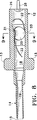
図1、4、12、18、20及び21において最もよくわかるように、本発明の眼内レンズインジェクターカートリッジ10、110、210及び310は、一般に、管状本体12、112、212、及び312と、インジェクションノズル14、114、214及び314とを有している。カートリッジ10、110、210及び310は、好ましくは、例えばポリプロピレンのような適切な熱可塑性物質で一体成形され、該熱可塑性物質は、例えば、言及によってその全内容が本明細書の一部をなすものとする米国特許第5716364号に開示されているような潤滑性促進物質(lubricity enhancing agent)を含んでいても良い。あるいは、カートリッジ10、110、210及び310は、ステンレス鋼、又は、チタンで製造されても良い。ノズル14、114、214及び314は、好ましくは、断面が円形、卵形又は長円形であり、約1.5〜6.5mm2 の断面積を有している。ノズル14、114、214及び314の末端の先端部15、115、215及び315は、好ましくは内外面とも丸められている。
【0013】
図4、12、18、19及び21において最もよくわかるように、好ましくは本体12、112、212及び312は、カートリッジ10、110、210及び310の操作を容易にすると共に、カートリッジ10、110、210及び310のインジェクションハンドピース(図示無し)への固定機構を提供するグリップ13、113、213及び313を含んでいる。図4において最もよくわかるように、本体12は、内腔18に連通している開口部16を含んでいても良い。開口部16により、IOL20がノズル14へ入った時、IOL20とハプティックス22を目視することが可能になる。あるいは、図12に示した第2の実施形態で示されるように、本体112が一体(solid)で開口部を有していなくても良く、又、図18に示した第3の実施形態で示されるように、本体212が、内腔218内のIOLの目視を可能にする一体(solid)の透明な窓224を含んでいても良い。更に、窓224はカートリッジ210内のIOLの正しい姿勢(correct orientation) を示すIOLの外形線226を備えていても良い。図1、4及び12で示された実施形態では、本体12及び112の近位端(proximal end)26及び126はそれぞれ、突起部(peg)28及び128を備えていても良く、図10に示すようにハプティックス22を前記突起部28及び128のまわりに巻きつけても良い。ハプティックス22をこのように方向決めすることにより、ハプティックス22が、IOL20を内腔18又は118内で移動させる機構によって捕捉されることを防止する。
【0014】
図5から図17及び図19において最もよくわかるように、内腔18、118及び218は横断面において非対称であって、断面の片側の面30、130及び230は円弧状に、他側の面32、132及び232は近位端26、126及び226の近くでは斜面になって(ramped)おり、ノズル14、114及び214の近くでは卵型又は円形断面へと変化する先細形状になっている。図6から図11で最もよくわかるように、IOL20が内腔18内を押されて移動する時、斜面側32がIOL20の縁部33を比較的平坦に保つ一方、内腔18の円弧側30は、IOL20の縁部31を丸める、又は折畳む。図6及び7に示すように、ノズル14の近くで斜面側32を徐々に丸くすることにより、縁部31が丸められた後で、斜面側32が縁部33を丸める、又は折畳むことが可能になる。このような非対称の構造は、一度にIOL20の片側をゆっくり折畳むので、IOLが例えば柔軟なアクリル樹脂等の粘弾性物質製の場合には、このように緩やかに折畳むことによって材料を折畳む際にIOL20を損傷する可能性を低減可能であるため、特に有効である。更に、本発明の非対称の折畳み作用は、ハプティックス22が内腔18の内部でIOL20によって妨げられ又は押さえつけられて損傷を受けることを防止する。
【0015】
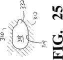
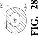
あるいは、図21から31でわかるように、内腔318は一方の側332で斜面であってもよいが、平坦なレッジ(ledge)又は棚部(shelf)334を備えていてもよい。棚部334は内腔318に沿って部分的にだけ延在し、装填(loading)の際にIOL20の適切な配置を確実にすることを補助する。
【0016】
内腔18、118、218及び318内のIOL20の移動をより円滑にするために、内腔18、118、218及び318の内部表面19、119、219及び319は、例えば言及によってそれらの全内容が本明細書の一部をなすものとする米国特許第4487865号、同4500676号、同4663233号、同4801475号、同4959074号、同5023114号及び同5037677号に記載されているような潤滑コーティング(lubricous coating)でコーティングされても良い。内腔18、118、218及び318は又、他の市販されている医用の粘弾性材、例えば、テキサス州フォートワースのアルコンラボラトリーズ社(Alcon Laboratories, Inc.)の粘弾性材VISCOAT(登録商標)等でコーティングされても良い。発明者は又、内部表面19、119、219及び319に綾(texture)を形成することにより、内部表面19、119、219、319とIOL20との間の表面接触量が最小化されると共に内部表面19、119、219、319とIOL20との間に粘弾性剤が保持されるようになるため、内腔18、118、218及び318内のIOL20の移動が補助されることを見出した。例えば、0.45ミクロンRMSより大きい表面粗さが使用され得る。刈り込み又は高平部効果(cropped or plateau effect)を得るために、このような仕上げ面は、最初にサンドブラスト又は酸腐食によってランダムなパターンの綾(texture)を設け、それに続いて、内腔18、118、218又は318の長手方向の軸に沿って特定方向に研磨する2段階の方法により生成される。
【0017】
本発明の幾つかの実施形態が上述されたが、これらの説明は例示及び説明の目的のために与えられたものである。上で開示された装置および方法からの変形、変更、改変及び新発展は、本発明の範囲と精神から逸脱することなく採用され得る。
【図面の簡単な説明】
【図1】 図1は、本発明の眼内レンズインジェクションカートリッジの第1実施形態の側面図である。
【図2】 図2は、本発明の眼内レンズインジェクションカートリッジの第1実施形態の正面図である。
【図3】 図3は、本発明の眼内レンズインジェクションカートリッジの第1実施形態の背面図である。
【図4】 図4は、本発明の眼内レンズインジェクションカートリッジの第1実施形態の平面図である。
【図5】 図5は、図1の線5−5に沿って取った本発明の眼内レンズインジェクションカートリッジの第1実施形態の縦断面図である。
【図6】 図6は、部分的に折畳まれた眼内レンズを示している図5と同様の本発明の眼内レンズインジェクションカートリッジの第1実施形態の縦断面図である。
【図7】 図7は、図6の線7−7に沿って取った本発明の眼内レンズインジェクションカートリッジの第1実施形態の横断面図である。
【図8】 図8は、眼内レンズの一方の側の初期の折畳みを示している図5及び図6と同様の本発明の眼内レンズインジェクションカートリッジの第1実施形態の縦断面図である。
【図9】 図9は、図7と同様であるが図8の線9−9に沿って取った本発明の眼内レンズインジェクションカートリッジの第1実施形態の横断面図である。
【図10】 図10は、内腔(bore)内における眼内レンズの初期位置を示している図5、図6及び図8と同様の本発明の眼内レンズインジェクションカートリッジの第1実施形態の縦断面図である。
【図11】 図11は、図3と同様であるが内腔内における眼内レンズの初期位置を示している本発明の眼内レンズインジェクションカートリッジの第1実施形態の背面図である。
【図12】 図12は、点線(shadow line)で内腔を示している本発明の眼内レンズインジェクションカートリッジの第2実施形態の斜視図である。
【図13】 図13は、図12の線13−13に沿って取った本発明で使用され得る内腔の横断面図である。
【図14】 図14は、図12の線14−14に沿って取った本発明で使用され得る内腔の横断面図である。
【図15】 図15は、図12の線15−15に沿って取った本発明で使用され得る内腔の横断面図である。
【図16】 図16は、図12の線16−16に沿って取った本発明で使用され得る内腔の横断面図である。
【図17】 図17は、図12の線17−17に沿って取った本発明で使用され得る内腔の横断面図である。
【図18】 図18は、本発明の眼内レンズインジェクションカートリッジの第3実施形態の平面図である。
【図19】 図19は、図18に示された本発明の眼内レンズインジェクションカートリッジの第3実施形態の背面図である。
【図20】 図20は、本発明の眼内レンズインジェクションカートリッジの第3実施形態の側面図である。
【図21】 図21は、本発明の眼内レンズインジェクションカートリッジの第4実施形態の平面縦断面図である。
【図22】 図22は、本発明の眼内レンズインジェクションカートリッジの第4実施形態の側面縦断面図である。
【図23】 図23は、図21の線23−23に沿って取った本発明で使用され得る内腔の横断面図である。
【図24】 図24は、図21の線24−24に沿って取った本発明で使用され得る内腔の横断面図である。
【図25】 図25は、図21の線25−25に沿って取った本発明で使用され得る内腔の横断面図である。
【図26】 図26は、図21の線26−26に沿って取った本発明で使用され得る内腔の横断面図である。
【図27】 図27は、図21の線27−27に沿って取った本発明で使用され得る内腔の横断面図である。
【図28】 図28は、図21の線28−28に沿って取った本発明で使用され得る内腔の横断面図である。
【図29】 図29は、図21の線29−29に沿って取った本発明で使用され得る内腔の横断面図である。
【図30】 図30は、図21の線30−30に沿って取った本発明で使用され得る内腔の横断面図である。
【図31】 図31は、図21の線31−31に沿って取った本発明で使用され得る内腔の横断面図である。[0001]
The present invention relates to an intraocular lens (IOL). More particularly, the present invention relates to a cartridge used for inserting an IOL into the eye.
[0002]
Background of the Invention The function of the human eye, simply put, is to transmit and refract light through an outer transparent part called the cornea, and focus the image with a lens on the retina at the back of the eye, To bring vision. The quality of the focused image depends on many factors, including the size, shape, and length of the eye, and the shape and transparency of the cornea and lens.
[0003]
When the transparency of the lens decreases due to damage, aging, or illness, the light that passes through the retina decreases, which reduces vision. This defect in the eye lens is medically known as cataract. The cure for this disease is to surgically remove the lens and implant an artificial lens or IOL.
[0004]
Early IOLs were made of hard plastics such as polymethyl methacrylate (PMMA), but flexible, foldable IOLs made of silicone, flexible acrylics and hydrogels are becoming increasingly popular. This is because these flexible lenses can be folded or rolled and inserted with a narrower incision. Several methods of rounding or folding the lens are used. One common method is to use an injector cartridge that folds the lens and is typically a relatively flexible plunger for pushing the lens into the eye with a plunger at the tip. It provides a small diameter lumen. The most commonly used injector cartridge configuration is disclosed in US Pat. No. 4,681,102 (Bartell), the entire contents of which are hereby incorporated by reference. Includes a split, longitudinally hinged cartridge. Similar configurations are disclosed in US Pat. Nos. 5,494,484 and 5,499,987 (Feingold) and US Pat. Nos. 5,616,148 and 5,620,450 (Egales, et al.). The entire contents of these documents are hereby incorporated by reference. US Pat. No. 5,275,604 (Rheinish, et al.), Which is intended to avoid the claims of US Pat. No. 4,681,102, the entire contents of which are hereby incorporated by reference, for example. A number of solid cartridges have been studied as seen in US Pat. No. 5,653,715 (Reich, et al.).
[0005]
All of the above prior art cartridges have a smooth, circular or oval cross-sectional lumen that is symmetric about a longitudinal axis. A smooth circular cross-section lumen works well for elastic materials such as silicones and hydrogels, but viscoelastic materials such as flexible acrylics can be easily rolled or folded For these lenses, it is preferable to round or fold them little by little to avoid damage to the optic and / or haptics.
[0006]
Therefore, there is a need for an IOL injector cartridge that gently folds the IOL.
[0007]
SUMMARY OF THE INVENTION The present invention improves upon prior art injector cartridges by providing a cartridge having an asymmetric bore. The asymmetric cross-sectional lumen begins to fold the lens on only one side, reducing the amount of energy imparted to the lens and the possibility of damaging the lens. Gently folding the lens also helps to define the transfer posture in the lumen of the haptic and reduces the possibility of damage to the haptic.
[0008]
Accordingly, it is an object of the present invention to provide a lens injector cartridge having an asymmetric cross-sectional lumen.
[0009]
Another object of the present invention is to provide a lens injector cartridge that gently folds a lens.
[0010]
Another object of the present invention is to provide a lens injector cartridge that minimizes the possibility of damage to the optics and / or haptics of the lens.
[0011]
Other objects, features and advantages of the present invention will become apparent with reference to the drawings, and the following description of the drawings and claims.
[0012]
As best seen in FIGS. 1, 4, 12, 18, 20, and 21, the intraocular
[0013]
As best seen in FIGS. 4, 12, 18, 19 and 21, preferably the
[0014]
As best seen in FIGS. 5 to 17 and 19, the
[0015]
Alternatively, as can be seen in FIGS. 21-31, the
[0016]
In order to make the movement of the
[0017]
While several embodiments of the present invention have been described above, these descriptions are given for purposes of illustration and description. Variations, changes, modifications and new developments from the apparatus and methods disclosed above may be employed without departing from the scope and spirit of the present invention.
[Brief description of the drawings]
FIG. 1 is a side view of a first embodiment of an intraocular lens injection cartridge of the present invention.
FIG. 2 is a front view of a first embodiment of an intraocular lens injection cartridge of the present invention.
FIG. 3 is a rear view of the first embodiment of the intraocular lens injection cartridge of the present invention.
FIG. 4 is a plan view of a first embodiment of an intraocular lens injection cartridge of the present invention.
FIG. 5 is a longitudinal sectional view of a first embodiment of the intraocular lens injection cartridge of the present invention taken along line 5-5 of FIG.
FIG. 6 is a longitudinal sectional view of a first embodiment of an intraocular lens injection cartridge of the present invention similar to FIG. 5 showing a partially folded intraocular lens.
7 is a cross-sectional view of the first embodiment of the intraocular lens injection cartridge of the present invention taken along line 7-7 of FIG. 6. FIG.
FIG. 8 is a longitudinal cross-sectional view of a first embodiment of an intraocular lens injection cartridge of the present invention similar to FIGS. 5 and 6 showing the initial folding of one side of the intraocular lens. .
FIG. 9 is a cross-sectional view of a first embodiment of the intraocular lens injection cartridge of the present invention, similar to FIG. 7, but taken along line 9-9 of FIG.
FIG. 10 is a view of the first embodiment of the intraocular lens injection cartridge of the present invention similar to FIGS. 5, 6 and 8 showing the initial position of the intraocular lens within the bore. It is a longitudinal cross-sectional view.
FIG. 11 is a rear view of the first embodiment of the intraocular lens injection cartridge of the present invention similar to FIG. 3 but showing the initial position of the intraocular lens within the lumen.
FIG. 12 is a perspective view of a second embodiment of the intraocular lens injection cartridge of the present invention showing the lumen with a dotted line.
13 is a cross-sectional view of a lumen that may be used with the present invention taken along line 13-13 of FIG. 12. FIG.
FIG. 14 is a cross-sectional view of a lumen that can be used in the present invention taken along line 14-14 of FIG.
FIG. 15 is a cross-sectional view of a lumen that can be used in the present invention taken along line 15-15 of FIG.
FIG. 16 is a cross-sectional view of a lumen that may be used with the present invention taken along line 16-16 of FIG.
FIG. 17 is a cross-sectional view of a lumen that may be used with the present invention taken along line 17-17 of FIG.
FIG. 18 is a plan view of a third embodiment of the intraocular lens injection cartridge of the present invention.
FIG. 19 is a rear view of the third embodiment of the intraocular lens injection cartridge of the present invention shown in FIG. 18;
FIG. 20 is a side view of a third embodiment of the intraocular lens injection cartridge of the present invention.
FIG. 21 is a plan longitudinal sectional view of a fourth embodiment of the intraocular lens injection cartridge of the present invention.
FIG. 22 is a side longitudinal sectional view of a fourth embodiment of the intraocular lens injection cartridge of the present invention.
FIG. 23 is a cross-sectional view of a lumen that can be used in the present invention taken along line 23-23 of FIG.
FIG. 24 is a cross-sectional view of a lumen that can be used in the present invention taken along line 24-24 of FIG.
FIG. 25 is a cross-sectional view of a lumen that may be used with the present invention taken along line 25-25 of FIG.
FIG. 26 is a cross-sectional view of a lumen that can be used with the present invention taken along line 26-26 of FIG.
FIG. 27 is a cross-sectional view of a lumen that can be used with the present invention taken along line 27-27 of FIG.
FIG. 28 is a cross-sectional view of a lumen that can be used with the present invention taken along line 28-28 of FIG.
FIG. 29 is a cross-sectional view of a lumen that can be used with the present invention taken along line 29-29 of FIG.
FIG. 30 is a cross-sectional view of a lumen that can be used in the present invention taken along line 30-30 of FIG.
FIG. 31 is a cross-sectional view of a lumen that can be used with the present invention taken along line 31-31 of FIG.
Claims (4)
a)内腔を有する本体であって、該内腔が横断面において非対称であって、一方の側で傾斜面と半径方向外側に膨出した曲面とを有し、前記傾斜面の反対の他方の側において棚部と半径方向外側に膨出した曲面とを備えている、本体と、
b)前記本体と一体に構成されたインジェクションノズルであって、前記本体の前記内腔と連通する内腔を有するノズルと、
を有する眼内レンズインジェクターカートリッジ。An intraocular lens injector cartridge,
a body having a a) lumen, be asymmetric lumen is in the transverse plane, and a curved surface that bulges to the inclined surfaces and a radially outwardly on one side, opposite the other of the inclined surfaces A main body comprising a shelf and a curved surface bulging radially outward on the side of
b) an injection nozzle configured integrally with the main body, the nozzle having a lumen communicating with the lumen of the main body;
An intraocular lens injector cartridge.
Applications Claiming Priority (5)
| Application Number | Priority Date | Filing Date | Title |
|---|---|---|---|
| US09/294,643 US6083231A (en) | 1998-06-02 | 1999-04-19 | Asymmetric intraocular lens injection cartridge |
| US09/294,643 | 1999-04-19 | ||
| US09/411,420 US6143001A (en) | 1998-06-02 | 1999-10-01 | Asymmetric intraocular lens injection cartridge |
| US09/411,420 | 1999-10-01 | ||
| PCT/US2000/007770 WO2000062712A1 (en) | 1999-04-19 | 2000-03-23 | Asymmetric intraocular lens injection cartridge |
Publications (3)
| Publication Number | Publication Date |
|---|---|
| JP2002541912A JP2002541912A (en) | 2002-12-10 |
| JP2002541912A5 JP2002541912A5 (en) | 2005-11-17 |
| JP3917373B2 true JP3917373B2 (en) | 2007-05-23 |
Family
ID=26968636
Family Applications (1)
| Application Number | Title | Priority Date | Filing Date |
|---|---|---|---|
| JP2000611850A Expired - Lifetime JP3917373B2 (en) | 1999-04-19 | 2000-03-23 | Asymmetric intraocular lens injection cartridge |
Country Status (12)
| Country | Link |
|---|---|
| US (1) | US6143001A (en) |
| EP (1) | EP1171058B1 (en) |
| JP (1) | JP3917373B2 (en) |
| AT (1) | ATE245954T1 (en) |
| AU (1) | AU768258B2 (en) |
| BR (2) | BR0009842A (en) |
| CA (1) | CA2362307C (en) |
| DE (1) | DE60004190T2 (en) |
| DK (1) | DK1171058T3 (en) |
| ES (1) | ES2203441T3 (en) |
| PT (1) | PT1171058E (en) |
| WO (1) | WO2000062712A1 (en) |
Families Citing this family (85)
| Publication number | Priority date | Publication date | Assignee | Title |
|---|---|---|---|---|
| SE9904338D0 (en) * | 1999-11-30 | 1999-11-30 | Pharmacia & Upjohn Ab | Intraocular lens implants |
| US8668735B2 (en) | 2000-09-12 | 2014-03-11 | Revision Optics, Inc. | Corneal implant storage and delivery devices |
| CA2421948C (en) | 2000-09-12 | 2009-12-22 | Anamed, Inc. | System for packaging and handling an implant and method of use |
| US6398789B1 (en) | 2000-10-19 | 2002-06-04 | Alcon Universal, Ltd. | Intraocular lens injector cartridge |
| US6554839B2 (en) | 2001-01-26 | 2003-04-29 | Advanced Medical Optics, Inc. | Stepped IOL insertion cartridge for inserting an intraocular lens in an eye |
| JP2002355268A (en) * | 2001-06-01 | 2002-12-10 | Nidek Co Ltd | Intraocular lens inserter |
| US6395028B1 (en) | 2001-07-18 | 2002-05-28 | Alcon Universal Ltd. | Anterior chamber phakic lens |
| US6537283B2 (en) | 2001-08-17 | 2003-03-25 | Alcon, Inc. | Intraocular lens shipping case and injection cartridge |
| US20030199978A1 (en) * | 2002-04-17 | 2003-10-23 | Lindsey Raymie H. | Stable anterior chamber phakic lens |
| US7476229B2 (en) | 2003-04-07 | 2009-01-13 | Anton Meyer & Co. Ag | Cartridge for an intraocular lens |
| JP4590505B2 (en) * | 2003-10-01 | 2010-12-01 | スター・ジャパン株式会社 | Intraocular lens insertion device |
| US10835371B2 (en) | 2004-04-30 | 2020-11-17 | Rvo 2.0, Inc. | Small diameter corneal inlay methods |
| US7776086B2 (en) | 2004-04-30 | 2010-08-17 | Revision Optics, Inc. | Aspherical corneal implant |
| US8057541B2 (en) | 2006-02-24 | 2011-11-15 | Revision Optics, Inc. | Method of using small diameter intracorneal inlays to treat visual impairment |
| WO2006006213A1 (en) * | 2004-07-09 | 2006-01-19 | Hoya Healthcare Corporation | Intraocular lens implanting instrument |
| US20060085013A1 (en) * | 2004-10-20 | 2006-04-20 | Vaclav Dusek | Intraocular lens inserter |
| ES2367787T3 (en) * | 2004-11-30 | 2011-11-08 | BAUSCH & LOMB INCORPORATED | TWO-PHASE ENVIRONMENT FOR INTRAOCULAR LENS INJECTOR. |
| EP1832247B1 (en) | 2004-12-27 | 2015-06-24 | Hoya Corporation | Intraocular lens implanting device |
| US20060167466A1 (en) * | 2005-01-21 | 2006-07-27 | Vaclav Dusek | Intraocular lens inserter system components |
| WO2006080191A1 (en) | 2005-01-26 | 2006-08-03 | Hoya Corporation | Intraocular lens insertion device |
| JP4836046B2 (en) | 2005-02-24 | 2011-12-14 | Hoya株式会社 | Intraocular lens insertion device |
| US20060235430A1 (en) * | 2005-04-15 | 2006-10-19 | Intralens Vision, Inc. | Corneal implant injector assembly and methods of use |
| US8574239B2 (en) | 2005-09-28 | 2013-11-05 | Hoya Corporation | Intraocular lens insertion device |
| JP4877643B2 (en) | 2005-12-08 | 2012-02-15 | Hoya株式会社 | Intraocular lens insertion device |
| US10555805B2 (en) | 2006-02-24 | 2020-02-11 | Rvo 2.0, Inc. | Anterior corneal shapes and methods of providing the shapes |
| JP4727497B2 (en) * | 2006-05-17 | 2011-07-20 | スター・ジャパン株式会社 | Lens insertion device for intraocular insertion |
| JP4927473B2 (en) | 2006-08-11 | 2012-05-09 | 興和株式会社 | Intraocular lens insertion device |
| US9730787B2 (en) | 2006-10-04 | 2017-08-15 | Hoya Corporation | Soft intraocular lens |
| US8900249B2 (en) * | 2006-10-23 | 2014-12-02 | Novartis Ag | Method of delivering temperature controlled intraocular lens |
| US9681947B2 (en) * | 2006-10-23 | 2017-06-20 | Novartis Ag | Intraocular lens delivery system with temperature control |
| EP2111820A1 (en) | 2007-01-17 | 2009-10-28 | Ajl, S.a. | Container for an intraocular lens and method for applying an intraocular lens |
| JP5470854B2 (en) * | 2007-02-08 | 2014-04-16 | 株式会社カネカ | Ophthalmic injector |
| US9271828B2 (en) | 2007-03-28 | 2016-03-01 | Revision Optics, Inc. | Corneal implant retaining devices and methods of use |
| US8162953B2 (en) | 2007-03-28 | 2012-04-24 | Revision Optics, Inc. | Insertion system for corneal implants |
| US9549848B2 (en) | 2007-03-28 | 2017-01-24 | Revision Optics, Inc. | Corneal implant inserters and methods of use |
| JP4517402B2 (en) * | 2007-04-26 | 2010-08-04 | Hoya株式会社 | Intraocular lens insertion cartridge |
| JP5236638B2 (en) | 2007-05-30 | 2013-07-17 | Hoya株式会社 | Intraocular lens insertion device |
| CN101677853B (en) | 2007-05-30 | 2012-04-18 | Hoya株式会社 | Intraocular lens inserting tool |
| JP5086713B2 (en) | 2007-07-11 | 2012-11-28 | Hoya株式会社 | Intraocular lens insertion device |
| US8668734B2 (en) | 2010-07-09 | 2014-03-11 | Powervision, Inc. | Intraocular lens delivery devices and methods of use |
| US8968396B2 (en) | 2007-07-23 | 2015-03-03 | Powervision, Inc. | Intraocular lens delivery systems and methods of use |
| JP5426547B2 (en) | 2007-07-23 | 2014-02-26 | パワーヴィジョン・インコーポレーテッド | Lens delivery system |
| US9610155B2 (en) | 2008-07-23 | 2017-04-04 | Powervision, Inc. | Intraocular lens loading systems and methods of use |
| US9849027B2 (en) | 2007-11-08 | 2017-12-26 | Alimera Sciences, Inc. | Ocular implantation device |
| BRPI0907725B8 (en) * | 2008-02-07 | 2023-04-04 | Alcon Inc | lens distribution system cartridge |
| US9539143B2 (en) | 2008-04-04 | 2017-01-10 | Revision Optics, Inc. | Methods of correcting vision |
| JP2011516180A (en) | 2008-04-04 | 2011-05-26 | レヴィジオン・オプティックス・インコーポレーテッド | Corneal inlay design and method for correcting vision |
| JP5254669B2 (en) | 2008-06-05 | 2013-08-07 | Hoya株式会社 | Intraocular lens insertion device and cartridge |
| JP5470753B2 (en) | 2008-06-17 | 2014-04-16 | Hoya株式会社 | Intraocular lens insertion device |
| US8273122B2 (en) | 2008-06-23 | 2012-09-25 | Abbott Medical Optics Inc. | Pre-loaded IOL insertion system |
| JP5323420B2 (en) | 2008-08-21 | 2013-10-23 | Hoya株式会社 | Intraocular lens insertion device |
| JP5416379B2 (en) | 2008-09-04 | 2014-02-12 | Hoya株式会社 | Intraocular lens insertion device |
| US8808308B2 (en) | 2008-10-13 | 2014-08-19 | Alcon Research, Ltd. | Automated intraocular lens injector device |
| US8801780B2 (en) | 2008-10-13 | 2014-08-12 | Alcon Research, Ltd. | Plunger tip coupling device for intraocular lens injector |
| US8308736B2 (en) | 2008-10-13 | 2012-11-13 | Alcon Research, Ltd. | Automated intraocular lens injector device |
| US20120226286A1 (en) * | 2008-10-16 | 2012-09-06 | Philip Douglas Weston | System and method for preparing a lenticular or corneal implant |
| US20100125278A1 (en) * | 2008-11-19 | 2010-05-20 | Wagner Christopher E | Hard and Soft Tip Intraocular Lens Injector System and Method |
| JP5415452B2 (en) * | 2008-12-01 | 2014-02-12 | 興和株式会社 | Intraocular lens insertion device |
| US8603103B2 (en) | 2009-01-07 | 2013-12-10 | Hoya Corporation | Intraocular lens insertion device |
| US9421092B2 (en) * | 2009-02-11 | 2016-08-23 | Alcon Research, Ltd. | Automated intraocular lens injector device |
| TWI513459B (en) | 2009-05-29 | 2015-12-21 | Alcon Res Ltd | Intraocular lens delivery system with a disposable plunger segment and method of use therefor |
| SG184032A1 (en) | 2010-04-08 | 2012-10-30 | Hoya Corp | Ocular implant insertion apparatus and methods |
| US8308799B2 (en) | 2010-04-20 | 2012-11-13 | Alcon Research, Ltd. | Modular intraocular lens injector device |
| JP5511530B2 (en) | 2010-06-10 | 2014-06-04 | Hoya株式会社 | Intraocular lens insertion device |
| WO2012018547A1 (en) | 2010-07-25 | 2012-02-09 | Alcon Research, Ltd. | Dual mode automated intraocular lens injector device |
| US8469948B2 (en) | 2010-08-23 | 2013-06-25 | Revision Optics, Inc. | Methods and devices for forming corneal channels |
| EP2608738B1 (en) | 2010-08-24 | 2015-09-16 | Abbott Medical Optics Inc. | Protective cap for an insertion device |
| BR112013015465A2 (en) | 2010-12-20 | 2016-09-27 | Novartis Ag | intraocular lens transfer case |
| EP2567674B1 (en) | 2011-09-07 | 2015-05-06 | SDI Surgical Device International GmbH | Modular intraocular lens injector |
| US8690941B2 (en) | 2011-10-04 | 2014-04-08 | Novartis Ag | Intraocular lens surgical system and method |
| KR101762932B1 (en) | 2011-10-21 | 2017-08-04 | 리비젼 옵틱스, 인크. | Corneal implant storage and delivery devices |
| US8657835B2 (en) | 2012-01-27 | 2014-02-25 | Alcon Research, Ltd. | Automated intraocular lens injector device |
| ES2834479T3 (en) | 2013-03-15 | 2021-06-17 | Alcon Inc | Method of reconfiguring an intraocular lens for delivery to a delivery device |
| JP6436287B2 (en) * | 2014-07-14 | 2018-12-12 | 株式会社ニデック | Intraocular lens insertion device |
| US10588780B2 (en) | 2015-03-04 | 2020-03-17 | Alcon Inc. | Intraocular lens injector |
| WO2016144404A1 (en) | 2015-03-12 | 2016-09-15 | Revision Optics, Inc. | Methods of correcting vision |
| AU2016324545A1 (en) | 2015-09-16 | 2018-04-12 | Hoya Corporation | Intraocular lens insertion tool |
| JP6646987B2 (en) | 2015-09-16 | 2020-02-14 | Hoya株式会社 | Intraocular lens insertion device |
| US10470875B2 (en) | 2016-06-23 | 2019-11-12 | Novartis Ag | IOL delivery systems |
| US10555807B2 (en) | 2016-06-24 | 2020-02-11 | Novartis Ag | Intraocular lens delivery device with telescoping plunger |
| CN109414344B (en) | 2016-06-28 | 2021-09-28 | Hoya株式会社 | Intraocular lens inserter |
| US10568735B2 (en) | 2017-01-13 | 2020-02-25 | Alcon Inc. | Intraocular lens injector |
| US11000367B2 (en) | 2017-01-13 | 2021-05-11 | Alcon Inc. | Intraocular lens injector |
| EP3863566A1 (en) | 2018-12-20 | 2021-08-18 | Alcon Inc. | Haptic optic management system utilizing edge rollers |
| US20230225857A1 (en) * | 2022-01-19 | 2023-07-20 | Johnson & Johnson Surgical Vision, Inc. | Insertion cartridges with reduced iol stress |
Family Cites Families (28)
| Publication number | Priority date | Publication date | Assignee | Title |
|---|---|---|---|---|
| US4573998A (en) * | 1982-02-05 | 1986-03-04 | Staar Surgical Co. | Methods for implantation of deformable intraocular lenses |
| US4487865A (en) | 1983-12-15 | 1984-12-11 | Biomatrix, Inc. | Polymeric articles modified with hyaluronate |
| US4681102A (en) * | 1985-09-11 | 1987-07-21 | Bartell Michael T | Apparatus and method for insertion of an intra-ocular lens |
| US4919130A (en) * | 1986-11-07 | 1990-04-24 | Nestle S.A. | Tool for inserting compressible intraocular lenses into the eye and method |
| US4747404A (en) * | 1986-11-10 | 1988-05-31 | Kresge Eye Institute Of Wayne State University | Foldable intraocular lens inserter |
| US4834094A (en) * | 1987-10-07 | 1989-05-30 | Patton Medical Technologies, Inc. | "Canoe" apparatus for inserting intra-ocular lens into the eye |
| AU623934B2 (en) * | 1988-10-07 | 1992-05-28 | Ioptex Research Inc | Intraocular lens insertion instrument |
| US5007913A (en) * | 1989-09-19 | 1991-04-16 | Alcon Surgical, Inc. | Apparatus and method for implantation of intraocular lenses |
| US5190552A (en) * | 1992-02-04 | 1993-03-02 | Kelman Charles D | Slotted tube injector for an intraocular lens |
| US5304182A (en) * | 1992-09-23 | 1994-04-19 | Kabi Pharmacia Ophthalmics, Inc. | Apparatus and method for curling and inserting flexible intraocular lenses |
| WO1994007436A1 (en) * | 1992-09-30 | 1994-04-14 | Vladimir Feingold | Intraocular lens insertion system |
| US5728102A (en) * | 1992-09-30 | 1998-03-17 | Staar Surgical Company, Inc. | Disposable intraocular lens insertion system |
| US5616148A (en) * | 1992-09-30 | 1997-04-01 | Staar Surgical Company, Inc. | Transverse hinged deformable intraocular lens injecting apparatus |
| US5620450A (en) * | 1992-09-30 | 1997-04-15 | Staar Surgical Company, Inc. | Transverse hinged deformable intraocular lens injecting apparatus |
| US5499987A (en) * | 1992-09-30 | 1996-03-19 | Staar Surgical Company | Deformable intraocular lens cartridge |
| US5275604A (en) * | 1992-12-03 | 1994-01-04 | Kabi Pharmacia Ophthalmics, Inc. | Contoured duct apparatus and method for insertion of flexible intraocular lens |
| DE4301573A1 (en) * | 1993-01-21 | 1994-07-28 | Marko Dr Med Obermaier | Folded lens insertion instrument in lens capsule of eye |
| US5653715A (en) * | 1993-03-09 | 1997-08-05 | Chiron Vision Corporation | Apparatus for preparing an intraocular lens for insertion |
| US5702402A (en) * | 1994-04-29 | 1997-12-30 | Allergal | Method and apparatus for folding of intraocular lens |
| US5803925A (en) * | 1995-01-17 | 1998-09-08 | Allergan | IOL insertion apparatus with covalently bonded lubricant |
| WO1996029956A1 (en) * | 1995-03-31 | 1996-10-03 | Aziz Yehia Anis | Intraocular lens implant and tool for implanting |
| DE19512640C2 (en) * | 1995-04-05 | 1997-01-30 | Winter & Ibe Olympus | Surgical endoscope instrument with HF working electrode |
| US5735858A (en) * | 1996-01-26 | 1998-04-07 | Allergan | IOL insertion apparatus and method for using same |
| US5716364A (en) * | 1996-07-10 | 1998-02-10 | Allergan | IOL insertion apparatus and method for making and using same |
| US5876406A (en) * | 1996-08-02 | 1999-03-02 | Staar Surgical Company, Inc. | Deformable intraocular lens injecting apparatus with transverse hinged lens cartridge |
| US5944725A (en) * | 1996-09-26 | 1999-08-31 | Bausch & Lomb Surgical, Inc. | Method and apparatus for inserting a flexible membrane into an eye |
| US5810834A (en) * | 1996-10-07 | 1998-09-22 | Chiron Vision Corporation | Tip formation for inserting a flexible membrane into an eye |
| US5947976A (en) * | 1998-06-02 | 1999-09-07 | Alcon Laboratories, Inc. | Asymmetric intraocular lens injection cartridge |
-
1999
- 1999-10-01 US US09/411,420 patent/US6143001A/en not_active Expired - Lifetime
-
2000
- 2000-03-23 PT PT00916639T patent/PT1171058E/en unknown
- 2000-03-23 ES ES00916639T patent/ES2203441T3/en not_active Expired - Lifetime
- 2000-03-23 BR BR0009842-6A patent/BR0009842A/en active IP Right Grant
- 2000-03-23 JP JP2000611850A patent/JP3917373B2/en not_active Expired - Lifetime
- 2000-03-23 DK DK00916639T patent/DK1171058T3/en active
- 2000-03-23 DE DE60004190T patent/DE60004190T2/en not_active Expired - Lifetime
- 2000-03-23 BR BRMU8003215-0U patent/BR8003215Y1/en not_active IP Right Cessation
- 2000-03-23 CA CA002362307A patent/CA2362307C/en not_active Expired - Lifetime
- 2000-03-23 EP EP00916639A patent/EP1171058B1/en not_active Expired - Lifetime
- 2000-03-23 AT AT00916639T patent/ATE245954T1/en active
- 2000-03-23 AU AU37713/00A patent/AU768258B2/en not_active Expired
- 2000-03-23 WO PCT/US2000/007770 patent/WO2000062712A1/en active IP Right Grant
Also Published As
| Publication number | Publication date |
|---|---|
| BR8003215Y1 (en) | 2009-08-11 |
| US6143001A (en) | 2000-11-07 |
| DE60004190T2 (en) | 2004-04-22 |
| CA2362307C (en) | 2008-07-22 |
| JP2002541912A (en) | 2002-12-10 |
| EP1171058B1 (en) | 2003-07-30 |
| PT1171058E (en) | 2003-11-28 |
| ATE245954T1 (en) | 2003-08-15 |
| DE60004190D1 (en) | 2003-09-04 |
| ES2203441T3 (en) | 2004-04-16 |
| AU3771300A (en) | 2000-11-02 |
| BR0009842A (en) | 2002-01-08 |
| AU768258B2 (en) | 2003-12-04 |
| EP1171058A1 (en) | 2002-01-16 |
| CA2362307A1 (en) | 2000-10-26 |
| DK1171058T3 (en) | 2003-11-24 |
| WO2000062712A1 (en) | 2000-10-26 |
Similar Documents
| Publication | Publication Date | Title |
|---|---|---|
| JP3917373B2 (en) | Asymmetric intraocular lens injection cartridge | |
| JP3553823B2 (en) | Intraocular lens injector cartridge and intraocular lens folding method | |
| US6537283B2 (en) | Intraocular lens shipping case and injection cartridge | |
| JP3655549B2 (en) | Improved plunger | |
| US6398789B1 (en) | Intraocular lens injector cartridge | |
| US6733507B2 (en) | Intraocular lens insertion apparatus | |
| CA2623752C (en) | Lens delivery system cartridge and method of manufacture | |
| CA2623906C (en) | Intraocular lens | |
| EP1967162A2 (en) | Lens delivery system cartridge | |
| JP2008212689A (en) | Lens delivery system | |
| WO2007087104A1 (en) | Improved plunger tip | |
| KR20060122930A (en) | Intraocular lens injector | |
| US20070265636A1 (en) | Lens delivery system | |
| MXPA01008678A (en) | Asymmetric intraocular lens injection cartridge | |
| WO2003043547A1 (en) | Method of tipping an intraocular lens injector cartridge |
Legal Events
| Date | Code | Title | Description |
|---|---|---|---|
| A521 | Request for written amendment filed |
Free format text: JAPANESE INTERMEDIATE CODE: A523 Effective date: 20040415 |
|
| A621 | Written request for application examination |
Free format text: JAPANESE INTERMEDIATE CODE: A621 Effective date: 20040415 |
|
| A131 | Notification of reasons for refusal |
Free format text: JAPANESE INTERMEDIATE CODE: A131 Effective date: 20060829 |
|
| A521 | Request for written amendment filed |
Free format text: JAPANESE INTERMEDIATE CODE: A523 Effective date: 20061121 |
|
| TRDD | Decision of grant or rejection written | ||
| A01 | Written decision to grant a patent or to grant a registration (utility model) |
Free format text: JAPANESE INTERMEDIATE CODE: A01 Effective date: 20070109 |
|
| A61 | First payment of annual fees (during grant procedure) |
Free format text: JAPANESE INTERMEDIATE CODE: A61 Effective date: 20070208 |
|
| R150 | Certificate of patent or registration of utility model |
Free format text: JAPANESE INTERMEDIATE CODE: R150 Ref document number: 3917373 Country of ref document: JP Free format text: JAPANESE INTERMEDIATE CODE: R150 |
|
| FPAY | Renewal fee payment (event date is renewal date of database) |
Free format text: PAYMENT UNTIL: 20100216 Year of fee payment: 3 |
|
| FPAY | Renewal fee payment (event date is renewal date of database) |
Free format text: PAYMENT UNTIL: 20110216 Year of fee payment: 4 |
|
| R250 | Receipt of annual fees |
Free format text: JAPANESE INTERMEDIATE CODE: R250 |
|
| FPAY | Renewal fee payment (event date is renewal date of database) |
Free format text: PAYMENT UNTIL: 20120216 Year of fee payment: 5 |
|
| R250 | Receipt of annual fees |
Free format text: JAPANESE INTERMEDIATE CODE: R250 |
|
| FPAY | Renewal fee payment (event date is renewal date of database) |
Free format text: PAYMENT UNTIL: 20130216 Year of fee payment: 6 |
|
| R250 | Receipt of annual fees |
Free format text: JAPANESE INTERMEDIATE CODE: R250 |
|
| FPAY | Renewal fee payment (event date is renewal date of database) |
Free format text: PAYMENT UNTIL: 20130216 Year of fee payment: 6 |
|
| FPAY | Renewal fee payment (event date is renewal date of database) |
Free format text: PAYMENT UNTIL: 20140216 Year of fee payment: 7 |
|
| R250 | Receipt of annual fees |
Free format text: JAPANESE INTERMEDIATE CODE: R250 |
|
| R250 | Receipt of annual fees |
Free format text: JAPANESE INTERMEDIATE CODE: R250 |
|
| R250 | Receipt of annual fees |
Free format text: JAPANESE INTERMEDIATE CODE: R250 |
|
| R250 | Receipt of annual fees |
Free format text: JAPANESE INTERMEDIATE CODE: R250 |
|
| R250 | Receipt of annual fees |
Free format text: JAPANESE INTERMEDIATE CODE: R250 |
|
| R250 | Receipt of annual fees |
Free format text: JAPANESE INTERMEDIATE CODE: R250 |
|
| R250 | Receipt of annual fees |
Free format text: JAPANESE INTERMEDIATE CODE: R250 |
|
| S111 | Request for change of ownership or part of ownership |
Free format text: JAPANESE INTERMEDIATE CODE: R313111 Free format text: JAPANESE INTERMEDIATE CODE: R313113 |
|
| R350 | Written notification of registration of transfer |
Free format text: JAPANESE INTERMEDIATE CODE: R350 |
|
| R250 | Receipt of annual fees |
Free format text: JAPANESE INTERMEDIATE CODE: R250 |
|
| R350 | Written notification of registration of transfer |
Free format text: JAPANESE INTERMEDIATE CODE: R350 |
|
| EXPY | Cancellation because of completion of term |