JP3911525B2 - Heat dissipation mechanism and electronic device having the heat dissipation mechanism - Google Patents
Heat dissipation mechanism and electronic device having the heat dissipation mechanism Download PDFInfo
- Publication number
- JP3911525B2 JP3911525B2 JP2003289348A JP2003289348A JP3911525B2 JP 3911525 B2 JP3911525 B2 JP 3911525B2 JP 2003289348 A JP2003289348 A JP 2003289348A JP 2003289348 A JP2003289348 A JP 2003289348A JP 3911525 B2 JP3911525 B2 JP 3911525B2
- Authority
- JP
- Japan
- Prior art keywords
- heat
- cooling fan
- heat sink
- electronic device
- housing
- Prior art date
- Legal status (The legal status is an assumption and is not a legal conclusion. Google has not performed a legal analysis and makes no representation as to the accuracy of the status listed.)
- Expired - Fee Related
Links
Images


Classifications
-
- H—ELECTRICITY
- H05—ELECTRIC TECHNIQUES NOT OTHERWISE PROVIDED FOR
- H05K—PRINTED CIRCUITS; CASINGS OR CONSTRUCTIONAL DETAILS OF ELECTRIC APPARATUS; MANUFACTURE OF ASSEMBLAGES OF ELECTRICAL COMPONENTS
- H05K1/00—Printed circuits
- H05K1/02—Details
- H05K1/0272—Adaptations for fluid transport, e.g. channels, holes
Landscapes
- Engineering & Computer Science (AREA)
- Microelectronics & Electronic Packaging (AREA)
- Cooling Or The Like Of Electrical Apparatus (AREA)
- Structure Of Printed Boards (AREA)
Description
本発明は、一般に放熱機構に係り、特に、電子機器に搭載された発熱性回路素子(発熱素子)から発生する熱を放出する冷却ファンを有する放熱機構に関する。本発明は、例えば、ノート型パーソナルコンピュータ(PC)のマザーボードに実装される各種回路素子の冷却ファンの取付方法に好適である。 The present invention generally relates to a heat dissipation mechanism, and more particularly to a heat dissipation mechanism having a cooling fan that releases heat generated from a heat-generating circuit element (heat-generating element) mounted on an electronic device. The present invention is suitable for, for example, a method of mounting a cooling fan for various circuit elements mounted on a motherboard of a notebook personal computer (PC).
ノート型PCのマザーボード(又はメインボード)は、CPUソケットや様々なメモリ(ソケット)、チップセット、拡張スロット及びBIOSROMなどの回路素子を実装し、PCの性能や機能を直接的に左右する。 A notebook PC motherboard (or main board) is mounted with circuit elements such as a CPU socket, various memories (sockets), a chip set, an expansion slot, and a BIOSROM, and directly affects the performance and functions of the PC.
近年のノート型PCは、マザーボードに搭載される各種回路素子の高速化と高機能化に伴って、発熱素子の数が増加すると共にかかる回路素子からの発熱量が増加する傾向にある。そこで、マザーボードに直接に又はソケット等を介して実装される発熱素子及びその他の回路素子を熱的に保護するためにマザーボードにはヒートシンクと呼ばれる冷却装置が設けられている。 In recent years, notebook PCs tend to increase the number of heat generating elements and the amount of heat generated from such circuit elements as the various circuit elements mounted on a motherboard increase in speed and functionality. Therefore, a cooling device called a heat sink is provided on the mother board in order to thermally protect the heat generating elements and other circuit elements mounted on the mother board directly or via a socket or the like.
ヒートシンクは典型的に多数の高伝熱性材料からなる冷却(又は放熱)フィンを有し、自然空冷によって発熱素子を冷却する。しかし、近年の発熱素子の発熱量は自然空冷では対応できなくなる傾向にある。そこで、ヒートシンクの冷却効果を高めるために冷却ファンを更に有するファン付ヒートシンクが提案されている。ファン付ヒートシンクはファンが発生する空気流によってヒートシンクを強制的に冷却する。従来のファン付ヒートシンクは、CPUからの発熱量が最も大きいために、典型的に、マザーボードのCPUの上部に設けられていた。 The heat sink typically has cooling (or heat radiation) fins made of a large number of highly heat-conductive materials, and cools the heating element by natural air cooling. However, the amount of heat generated by the heating elements in recent years tends not to be able to cope with natural air cooling. Therefore, a heat sink with a fan that further includes a cooling fan has been proposed in order to enhance the cooling effect of the heat sink. The heat sink with fan forcibly cools the heat sink by the air flow generated by the fan. Conventional heat sinks with fans have the largest amount of heat generated from the CPU, and are typically provided above the CPU of the motherboard.
冷却ファンは、マザーボードの一面に対して垂直に配向する横型と、平行に配向する縦型とに分類することができる。しかし、ある程度の厚さを必要とする縦型よりも横型の方が薄型化(ロープロフィール化)が要請されている近年のノート型PCに適している。 The cooling fan can be classified into a horizontal type oriented perpendicular to one surface of the motherboard and a vertical type oriented parallel. However, the horizontal type is more suitable for recent notebook PCs that are required to be thinner (low profile) than the vertical type that requires a certain thickness.
しかし、マザーボードのヒートシンク設置面の裏面にも発熱素子は設置される。従来はこれらの発熱量は無視できる程度であったが、近年の高速化及び高機能化から発熱量は無視できなくなり、当該発熱素子及びその他の回路素子の熱破壊、熱劣化及び誤動作、マザーボードを収納する筐体の熱変形や低温火傷等の影響も大きくなってきた。このため、近年ではマザーボードの両面(表裏面)を冷却する必要が生じてきた。 However, a heating element is also installed on the back side of the heat sink installation surface of the motherboard. Conventionally, these calorific values were negligible, but with the recent increase in speed and functionality, the calorific values can no longer be neglected, causing thermal destruction, thermal degradation and malfunction of the heating elements and other circuit elements, The effects of thermal deformation, low temperature burns, etc. on the housing to be accommodated have also increased. For this reason, in recent years, it has become necessary to cool both surfaces (front and back surfaces) of the motherboard.
これに対して、両面に冷却ファンを設けることが考えられるが、かかる方法は、製造コストの増加、冷却ファンを駆動するための電力消費の増加、及び、冷却ファンの駆動に伴う雑音の増大を伴う。 On the other hand, it is conceivable to provide cooling fans on both sides, but such a method increases the manufacturing cost, increases the power consumption for driving the cooling fan, and increases the noise accompanying the driving of the cooling fan. Accompany.
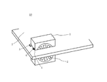
そこで、マザーボードの両面を一の冷却ファンにより冷却する放熱機構が公開実用新案公報平成6年第13364号によって提案されている。かかる放熱機構10は、図7に示すように、外枠1、冷却ファン2、固定舌片3、コネクタ4、マザーボード5及びコネクタ6を有する。ここで、図7は、従来の放熱機構10の概略斜視図である。外枠1は、その両側に設けられた固定部品3及び図示しないネジを介してマザーボード5に設けられた貫通孔に固定される。この結果、コネクタ4及び6が電気的に接続し、冷却ファン2はマザーボード5と電気的に接続する。
Therefore, a heat radiation mechanism for cooling both sides of the motherboard with a single cooling fan is proposed in Japanese Utility Model Publication No. 13364. As shown in FIG. 7, the
図7に示す冷却ファン2は、外枠1をマザーボード5に埋め込むため、マザーボード5の両面を同時に冷却することができる。また、外枠1に付けられた固定部品3の取付位置を任意の個所に上下移動すれば、外枠1のマザーボード5に対する取付高さが変化するため、より発熱量の多い面を効果的に冷却することもできる。
Since the
しかし、冷却ファン2は縦型であるため、上述したように、ロープロファイルなノート型PCには不向きである。このため、マザーボードの両面を効率よく冷却することができ、かつ、ノート型PCの薄型化を妨げない放熱機構が要請されていた。
However, since the
そこで、本発明は、このような従来の課題を解決する新規かつ有用な放熱機構及びかかる放熱機構を有する電子機器を提供することを本発明の概括的目的とする。 SUMMARY OF THE INVENTION Accordingly, it is a general object of the present invention to provide a new and useful heat dissipation mechanism that solves such conventional problems and an electronic apparatus having such a heat dissipation mechanism.
より特定的には、本発明は、発熱素子及びその他の電子部品の熱破壊、熱劣化及び誤動作やそれらを収納する筐体の熱変形及び低温火傷を防止しつつ、プリント基板を有する電子機器の薄型化を妨げない放熱機構及びかかる放熱機構を有する電子機器を提供することを例示的目的とする。 More specifically, the present invention relates to an electronic device having a printed circuit board while preventing thermal destruction, thermal deterioration and malfunction of a heating element and other electronic components and thermal deformation and low-temperature burn of a housing for housing them. It is an exemplary object to provide a heat dissipation mechanism that does not hinder thinning and an electronic device having such a heat dissipation mechanism.
上記目的を達成するために、本発明の例示的一態様としての放熱機構は、発熱性部品を実装するための基板であり、貫通孔を有する基板と、前記基板の一面に対して垂直に配向する冷却ファンとを有し、前記冷却ファンは前記一面の放熱が可能であり、前記貫通孔は、前記冷却ファンに当該貫通孔を通じて前記一面の裏面の放熱を可能とする。かかる放熱機構は横型冷却ファンを有するため、縦型冷却ファンを使用する場合よりも当該プリント基板を収納する電子機器の筐体の薄型化を妨げない。冷却ファンはそれが設置されている面の放熱には貫通孔を使用しない。また、貫通孔は冷却ファンに裏面の冷却を可能にする寸法を有する。この結果、一の冷却ファンにより裏面の放熱も簡易に行うことができる。冷却ファンは典型的には基板に設けられるが、基板を収納する筐体側に設けられてもよい。 In order to achieve the above object, a heat dissipation mechanism as an exemplary embodiment of the present invention is a substrate for mounting a heat-generating component, and is oriented perpendicularly to a substrate having a through hole and one surface of the substrate. The cooling fan can dissipate heat on the one surface, and the through hole allows heat radiation on the back surface of the one surface through the through hole to the cooling fan. Since such a heat dissipation mechanism has a horizontal cooling fan, it does not hinder a reduction in the thickness of the casing of the electronic device that houses the printed circuit board as compared with the case where the vertical cooling fan is used. The cooling fan does not use a through hole for heat dissipation of the surface on which it is installed. The through hole has a dimension that allows the cooling fan to cool the back surface. As a result, heat radiation on the back surface can be easily performed by one cooling fan. The cooling fan is typically provided on the substrate, but may be provided on the housing side that accommodates the substrate.
前記放熱機構はヒートシンクを有し、前記冷却ファンは前記ヒートシンクに設けられてもよい。この場合、ファン付ヒートシンクは冷却機能を高めると共に冷却フィンと冷却ファンとが同一平面上にあるので放熱機構の薄型化に寄与する。また、前記発熱性部品は、例えば、プロセッサであり、前記基板は、例えば、マザーボードであり、前記冷却ファンは、例えば、前記マザーボードの前記プロセッサと同一面側に設けられる。プロセッサはCPUを包括し得る概念である。かかる場合には、放熱機構は従来から通常設けられるCPU用のファン付ヒートシンクの冷却ファンを本発明の放熱機構の冷却ファンにそのまま利用することができ、多機能化を図ることができる。 The heat dissipation mechanism may include a heat sink, and the cooling fan may be provided on the heat sink. In this case, the heat sink with a fan enhances the cooling function and contributes to the thinning of the heat dissipation mechanism because the cooling fin and the cooling fan are on the same plane. The exothermic component is, for example, a processor, the substrate is, for example, a motherboard, and the cooling fan is provided on the same side as the processor of the motherboard, for example. A processor is a concept that can include a CPU. In such a case, the heat dissipating mechanism can use the cooling fan of the heat sink with fan for CPU, which is normally provided conventionally, as it is for the cooling fan of the heat dissipating mechanism of the present invention, and can be multi-functionalized.
前記放熱機構はヒートパイプを有し、前記冷却ファンは前記ヒートパイプにより伝えられる熱を冷却してもよい。また、前記ヒートパイプと前記ヒートシンクは熱的に接続されている。前記ヒートパイプは、前記貫通孔を通じて、前記一面と前記一面の裏面間に配置されていてもよい。この場合、放熱機構は前記ヒートパイプを特定の発熱源(発熱性部材)と連結すれば、その部分を効率的又は集中的に冷却することができる。 The heat dissipation mechanism may include a heat pipe, and the cooling fan may cool the heat transmitted by the heat pipe. The heat pipe and the heat sink are thermally connected. The heat pipe may be disposed between the one surface and the back surface of the one surface through the through hole. In this case, if the heat radiating mechanism connects the heat pipe to a specific heat source (heat generating member), the portion can be efficiently or intensively cooled.
前記冷却ファンは、前記貫通孔と連通する吸気口を有することができる。かかる場合には、冷却ファンは吸気口及び貫通孔を介して裏面の放熱を行うことができる。なお、前記吸気口は前記冷却ファンを収納する筐体を貫通してもよい。 The cooling fan may have an air inlet that communicates with the through hole. In such a case, the cooling fan can dissipate heat on the back surface through the air inlet and the through hole. The intake port may pass through a housing that houses the cooling fan.
本発明の例示的一態様としての電子機器は、第1及び第2の面と、当該第1及び第2の面を貫通する貫通孔とを有する基板と、当該基板の前記第1及び第2の面に実装される発熱性部品と、前記第1の面に垂直に配向して前記第1の面を放熱すると共に、前記貫通孔を介して前記第2の面を放熱する冷却ファンと、前記基板と前記冷却ファンを収納する筐体とを有する。かかる電子機器は上述の放熱機構を有するために筐体の薄型化を維持しつつ基板の両面を効率的に冷却することができる。かかる電子機器は、ノート型PC、ワードプロセッサ、パーソナル・ディジタル・アシスタンツ(PDA)その他の携帯型電子機器(携帯型ゲーム装置、各種ドライブなど)に好適である。 An electronic apparatus as an exemplary aspect of the present invention includes a substrate having first and second surfaces, a through-hole penetrating the first and second surfaces, and the first and second surfaces of the substrate. A heat-generating component mounted on the surface, a cooling fan that is oriented perpendicularly to the first surface and dissipates the first surface, and dissipates the second surface through the through hole, A housing for housing the substrate and the cooling fan; Since such an electronic apparatus has the above-described heat dissipation mechanism, both surfaces of the substrate can be efficiently cooled while maintaining a thin casing. Such electronic devices are suitable for notebook PCs, word processors, personal digital assistants (PDAs) and other portable electronic devices (portable game devices, various drives, etc.).
前記電子機器は多数の冷却フィンを有するヒートシンクを更に有し、前記冷却ファンと前記ヒートシンクはファン付ヒートシンクを構成し、前記冷却ファンと前記冷却フィンは同一平面上に配置されてもよい。この場合、ファン付ヒートシンクは冷却機能を高めると共に冷却フィンと冷却ファンとが同一平面上にあるのでファン付ヒートシンク自体の薄型化に寄与する。また、前記発熱性部品は、例えば、プロセッサであり、前記基板は、例えば、マザーボードであり、前記冷却ファンは、例えば、前記マザーボードの前記プロセッサと同一面側に設けられる。プロセッサはCPUを包括し得る概念である。かかる場合には、前記電子機器はノート型PCであれば放熱効果の高いロープロフィールのノート型PCを提供することができる。また、電子機器は従来から通常ノート型PCに設けられるCPU用のファン付ヒートシンクの冷却ファンを本発明の電子機器の冷却ファンにそのまま利用することができ、多機能化を図ることができる。 The electronic device may further include a heat sink having a plurality of cooling fins, the cooling fan and the heat sink may constitute a heat sink with a fan, and the cooling fan and the cooling fin may be disposed on the same plane. In this case, the heat sink with fan enhances the cooling function, and the cooling fin and the cooling fan are on the same plane, which contributes to a reduction in thickness of the heat sink with fan itself. The exothermic component is, for example, a processor, the substrate is, for example, a motherboard, and the cooling fan is provided on the same side as the processor of the motherboard, for example. A processor is a concept that can include a CPU. In such a case, if the electronic device is a notebook PC, a low profile notebook PC having a high heat dissipation effect can be provided. In addition, the electronic device can conventionally use the cooling fan of the heat sink with a fan for CPU normally provided in the notebook type PC as the cooling fan of the electronic device of the present invention, and can be multifunctional.
前記電子機器はヒートパイプを有し、前記冷却ファンは前記ヒートパイプにより伝えられる熱を冷却してもよい。この場合、電子機器は前記ヒートパイプを特定の発熱源(発熱性部材)と連結すれば、その部分を効率的又は集中的に冷却することができる。 The electronic apparatus may include a heat pipe, and the cooling fan may cool the heat transmitted by the heat pipe. In this case, the electronic device can cool the portion efficiently or intensively by connecting the heat pipe to a specific heat source (heat generating member).
前記冷却ファンは、前記貫通孔と連通する吸気口を有することができる。かかる場合には、冷却ファンは吸気口及び貫通孔を介して裏面の放熱を行うことができる。なお、前記吸気口は前記冷却ファンを収納する筐体を貫通してもよい。 The cooling fan may have an air inlet that communicates with the through hole. In such a case, the cooling fan can dissipate heat on the back surface through the air inlet and the through hole. The intake port may pass through a housing that houses the cooling fan.
本発明の他の目的と更なる特徴は、以下、添付図面を参照して説明される実施例において明らかになるであろう。 Other objects and further features of the present invention will become apparent from the embodiments described below with reference to the accompanying drawings.
本発明の放熱機構及び電子機器によれば、横型冷却ファンが縦型冷却ファンを使用する場合よりもプリント基板を収納する電子機器の筐体の薄型化を妨げない。また、一の冷却ファンにより裏面の放熱も簡易に行うことができ、プリント基板上の回路素子の熱破壊、熱劣化及び誤動作を防止することができる。 According to the heat dissipation mechanism and the electronic device of the present invention, it is possible to prevent the casing of the electronic device that houses the printed circuit board from being thinner than the case where the horizontal cooling fan uses the vertical cooling fan. In addition, heat radiation on the back surface can be easily performed by one cooling fan, and thermal destruction, thermal deterioration, and malfunction of the circuit elements on the printed circuit board can be prevented.
以下、図1乃至図4を参照して、本発明の例示的一態様としての放熱機構100を説明する。本発明の放熱機構は少なくとも横型冷却ファンを含むが、本実施例はファン付ヒートシンク110の冷却ファン130を利用している。本実施例の放熱機構100は、ファン付ヒートシンク110と貫通孔166を有するマザーボード160によって構成される。ここで、図1は、本発明の例示的一態様としての放熱機構100の分解斜視図である。また、図2は、放熱機構100のマザーボード160の裏面を示す斜視図である。図3は、図1に示すファン付ヒートシンク110を示す概略拡大斜視図である。図4は、図3のファン付ヒートシンク110の内部を示す斜視図である。
Hereinafter, a heat dissipation mechanism 100 as an exemplary embodiment of the present invention will be described with reference to FIGS. 1 to 4. Although the heat dissipation mechanism of the present invention includes at least a horizontal cooling fan, this embodiment uses the cooling
本実施例の放熱機構100は、図1に点線で示すCPU150(又は、MPUとも称する。広義では、プロセッサを意味するものであって、以下、本出願では、同様に扱うものとする。)を冷却するためにCPU150上に熱的に接触して設けられるファン付ヒートシンク110を利用している。ファン付ヒートシンク110は、筐体120と、冷却ファン130と、複数の冷却フィン140(図4)とを有している。
The heat dissipation mechanism 100 of the present embodiment is a CPU 150 (also referred to as MPU, which is indicated by a dotted line in FIG. 1, which means a processor in a broad sense, and will be treated similarly in the present application hereinafter). A
筐体120は、例えば、アルミニウム、銅、窒化アルミニウム、人工ダイヤモンド、プラスチック等の高熱導電性材料から構成されるほぼ直方体形状フレームであり、上面122と、取付孔123aと、取付溝123bと、下面124と、吸気口125と、端面126と、排気口127と、収納部128とを有する。ヒートシンク110は板金加工、アルミダイキャストその他の方法によって製造される。筐体120は、プラスチック製であれば、例えば、射出成形によって形成されてもよい。筐体120の一部(例えば、冷却ファン130と冷却フィン140)は分割可能であってもよい。
The
ここで、吸気口125は、筐体120の上面側122と下面側124の両方に設けられている。図3に示すように、吸気口125は、上面122と下面124を貫通している。よりわかり易くは、図4で示すように、下面側124にも吸気口125が設けられているのが判る。このファン付きヒートシンク110(図1、図3)は、ヒートシンク110の上下面122及び124の両面から吸気が可能である。
Here, the
冷却ファン130及び/又は冷却フィン140の交換又は保守の便宜のために、筐体120の上面122は、図4に示すように、蓋部として、下面124を含む本体部から取り外し可能に構成されることが好ましい。代替的に、図1に示すヒートシンク110の代わりに図4に示す蓋部のないヒートシンクを使用することもできるが、冷却ファン130の回転に伴う騒音を低減するために蓋部が設けられることが好ましい。
For convenience of replacement or maintenance of the cooling
筐体120は、冷却ファン130と冷却フィン140とを収納部128に収納している。収納部128は冷却ファン130を収納する半円部と冷却フィン140を収納する直方部とを有する。収納部128は、冷却ファン130が発生する空気流が通過する風洞空間としても機能する。筐体120もその表面から放熱を行うことができるので、必要があれば、上下面122及び124その他の面を突起状にして表面積を増大させて放熱効果を高めてもよい。
The
図1において、取付孔123a及び取付溝123bは上下面122及び124を貫通してビス170と係合する。ビス170を中空にして、マザーボード160に設けられたCPU150を設置用のソケット151を貫通するピン172と係合可能に構成してもよい。ソケット151はCPU150を交換可能にする。代替的に、ビス170はマザーボード160の図示しない孔を貫通してマザーボード160に、必要があれば、図示しないナットなどを介して固定される。この結果、筐体120は、取付孔123a及び取付溝123bとビス170を介して、マザーボード160に固定される。もっとも、筐体120とCPU150を熱的に接続する手段は問わない。例えば、両者を熱伝導性接着剤や半だ付け(クリーム半だとリフロー炉を利用するなど)によって接着したり、先端にスリット付頭部を有する取付ピンをマザーボード160の後述する面164から挿入して取付孔123a及び取付溝123bから突出した部分にコイルばねを掛けて固定したりしてもよい。
In FIG. 1, the mounting
図1、図3及び図4において、吸気口125は、上下面122及び124を貫通して冷却ファン130を外部に連通させる。また、吸気口125はマザーボード160の後述する貫通孔166に連通している。端面126には排気口127が設けられており、冷却ファン130及び冷却フィン140に連通している。吸気口125は、CPU150からの発熱と共に、広くマザーボード160に実装されている発熱素子からの暖気を筐体120内に導入する機能を有する。
In FIG. 1, FIG. 3 and FIG. 4, the
この結果、吸気口125は、上下面122及び124においてマザーボード160の後述する面162側の暖気を筐体120内に導入することができ、下面124において貫通孔166を介してマザーボード160の後述する面164からの暖気を筐体120内に導入することができる。即ち、冷却ファン130の両側(122及び124側)から、筐体120内に導入できる。導入された暖気は冷却ファン130によって後述する冷却フィン140に供給されて熱交換を経た後で排気口127から排気される。導入された暖気はかかる熱交換により冷却される。排気口127は、後述するノート型PC200の側部225に内蔵されている図示しない放熱用板金又は側部225に設けられた排気口付近に連通している。また、上述したように、暖気の熱は筐体120の表面からも放出される。
As a result, the
吸気口125は、本実施例では、冷却ファン130の全部が外部に露出する程度の大きさを有するが、その大きさは任意に設定することができ、また、必要があれば、複数の孔(例えば、メッシュ構造)から構成されてもよい。
In this embodiment, the
必要があれば、筐体120は、例えば、下面124を有する底部を中空にして冷却水(水その他の冷媒(例えば、フレオン、アルコール、アンモニア、ガルデン、フロン等))を収容してヒートパイプ板を構成してもよい。また、中空部にメッシュ(又はウイック)を挿入して毛細管現象により冷却水を還流させると更に効果的である。また、筐体120は、必要があれば、外部のヒートパイプなどと接続されてもよい。ここで、ヒートパイプは、アルミニウム、ステンレス、銅などで形成された高低差のあるパイプを有する。パイプは、その内側にガラス繊維や網状の細い銅線などで形成したウイック材を張り、内部を減圧にして水などの冷却水を収納する。低位置にある発熱体から熱を得ると冷却水が気化して高位置に移動し、高位置において自然又は強制冷却されて再び液化して低位置に戻るサイクルを繰り返して発熱体を冷却する。前記ヒートパイプを特定の発熱源と連結すれば、その部分を効率的又は集中的に冷却が可能となる。
If necessary, the
また、他の実施の形態として、貫通孔166を利用して、ファン付きヒートシンク110に接続されたヒートパイプ61をマザーボード160の裏面164に延伸させることが可能である。この実施の形態を図6に示す。図6のファン付きヒートシンク1100の側面にヒートパイプ61が連結されている。ヒートパイプ61は、マザーボード160の上面162から貫通孔166を通じてマザーボード160の裏面164に延伸する。図6中のヒートパイプ61の点線部で、吸気口125の下に位置する部分がマザーボード160の貫通孔166を通過する。なお、図6では、マザーボード160の図は省略している。ヒートパイプ61は、裏面164側で発熱性の電子部品などと図中の62の位置で連結して、その熱をファン付きヒートシンク1100に移動させる。従って、ヒートパイプ61により伝えられる熱が冷却ファン130により放熱される。この構成により、貫通孔166の裏面164からの吸気とヒートパイプの配置に兼用が可能となる。なお、図6のファン付きヒートシンク1100の構造は、図1、図3及び図4のファン付きヒートシンク110と、ヒートパイプ61が連結されている以外は、同じである。従って、図6では、冷却ファン130などの図は省略する。
As another embodiment, the
冷却ファン130は回転して空気流を発生することによって冷却フィン140を強制的に冷却する。冷却ファン130は、動力部132と、動力部132に固定されるプロペラ部134とを有する。動力部132は、典型的に、回転軸と、回転軸の周りに設けられたベアリングと、ベアリングハウスと、モータを構成する磁石とを有するが、動力部132は当業界で周知のいかなる構造も使用することができるので、ここでは詳細な説明は省略する。もっとも、ベアリングハウスへの電熱を防止するためにベアリングハウスの内周壁面に断熱部が形成されることが好ましい。断熱部は、例えば、フッ素系樹脂、シリコン系樹脂などの低伝熱性材料を薄膜上にして形成される。
The cooling
プロペラ部134は所望の角度に形成された所望の数の回転翼を有する。回転翼は等角的又は非等角的に配置され、所望の寸法を有する。冷却ファン130は、動力部132とプロペラ部134とは分割可能でも分割不能でもよい。なお、冷却ファン130に接続される配線は図示が省略されている。前述した通り、冷却ファン130は、吸気口125が筐体120の両側(122及び124側)に設けられているので、両側から吸気することができる。
The
本実施例の冷却ファン130は、マザーボード160の一面(表面162)に対して垂直に配向しているために横型である。このため、後述するノート型PC200に収納された場合にそのベース220をロープロフィールに維持することができる。また、冷却ファン130は以下に説明する冷却フィン140と同一平面上に配置されており、かかる構造も後述するノート型PC200のベース220の薄型化に寄与する。上述したように、冷却ファン130の下部にはマザーボード160の貫通孔166が位置している。
The cooling
冷却フィン140は整列した多数の板状フィン142から構成されている。冷却フィン140は凸形状を有して表面積を増加させているので放熱効果が増加している。もっともフィン142の形状は板状に限定されず、ピン状、湾曲形状など任意の配置形状を採用することができる。また、フィン142は、一定間隔で横に整列する必要はなく、放射状に配置されたり、下面124に対して傾斜して配置されたりしてもよい。また、フィン142は冷却ファン130の周りに配置されてもよい。フィン142の数も任意に設定することができる。フィン142はアルミニウム、銅、窒化アルミニウム、人工ダイヤモンド、プラスチックなどの高熱伝導性材料で形成されることが好ましい。フィン142は、金型成形、圧入、ロウ付け、溶接、射出成形などによって形成される。
The cooling
収納部128のうち冷却フィン140を載置する部分の真下にCPU150が配置される。換言すれば、取付孔123a及び取付溝123bで囲まれた部分の収納部に冷却フィン140は形成される。冷却フィン140とCPU150とは熱的に接続しており、この結果、CPU150からの熱は効率的に冷却フィン140に熱伝達される。また、冷却フィン140は冷却ファン130からの送風を受けて効率よく放熱を行うことができる。
The
本実施例のファン付ヒートシンク110は、冷却ファン130が冷却フィン140の上部に配置される構造よりも放熱効率が一般に高い。これは、(1)冷却ファンが冷却フィンの上部にあると、動力部の真下にある冷却フィンの部分にプロペラ部からの送風量が少なくなり効果的な冷却が行えないこと、及び、(2)CPUの発熱源はその中央部に集中していること、などによる。しかし、本実施例の冷却フィン140は、動力部132による送風の妨害を受けないので高い放熱効率を有する。
The heat sink with
選択的に、冷却フィン140と上面122とをその間に熱伝導弾性体(例えば、シリコンゴムなど)を介在させることにより熱伝導させて法熱効果を高めてもよい。かかる構造は、冷却フィン140が冷却ファン130の回転に伴う振動及び振動に伴う雑音の除去にも寄与する。熱伝導弾性体が冷却ファン130の回転に伴う振動を吸収することによりビス170の緩みも防止することができる。
Alternatively, the thermal fin effect may be enhanced by thermally conducting the cooling
本実施例は、上述したように、ファン付ヒートシンクを利用している。通常、CPU150の冷却用にヒートシンクが設けられているため、かかるヒートシンクがファン付ヒートシンクである場合に、本発明の放熱機構100は新たな冷却ファンを必要とせずにファン付ヒートシンク内の冷却ファンを多機能化している。これによって、新たな冷却ファンを設ける場合の製造コストの増加、消費電力の増大、冷却ファンの回転に伴う雑音の増大を抑えることができる。
In this embodiment, as described above, a heat sink with a fan is used. Usually, since a heat sink is provided for cooling the
また、冷却ファンが冷却フィンの上部に配置されるファン付ヒートシンクを使用する代わりに冷却ファンが冷却フィンと同一平面上に配置されたファン付ヒートシンク110を利用している。かかる構造は冷却ファン130とマザーボード160の貫通孔166との連通を容易にする。もっとも、冷却ファン130とマザーボード160の貫通孔166との連通が確保される限り、冷却ファン130と冷却フィン140とは同一平面上に配置される必要はないことが理解されるであろう。
Further, instead of using a heat sink with a fan in which the cooling fan is disposed on the top of the cooling fin, a heat sink with
本発明の放熱機構100に使用される冷却ファン130は必ずしもファン付ヒートシンクの一部である必要はない。例えば、CPU150の冷却装置を単に冷却フィン140のみを有するヒートシンクとして、冷却ファン130を冷却フィン140とは無関係に配置してもよい。例えば、冷却ファン130は、図1においてマザーボード160の右側(即ち、冷却フィン140と反対側)に設けてもよいし、マザーボード160の面164側に設けてもよい。また、冷却ファン130はマザーボード160に実装されることは必ずしも必要ではなく、マザーボード160を収納するノート型PC200のベース220や放熱用板金その他の部材に取り付けてもよい。換言すると、本発明の放熱機構100に使用される冷却ファン130は貫通孔166を介してマザーボード160の両面162及び164の暖気を引き込んで放熱を行える限り、更に、冷却フィン140の強制冷却を行うかどうかは選択的である。例えば、冷却ファン130は、マザーボード160の両面162及び164の暖気をベース220に設けられた図示しないメッシュ状の排気口から換気するだけでも足りる。
The cooling
マザーボード160はCPUソケット151や様々なメモリ(ソケット)、チップセット、拡張スロット及びBIOSROMなどの回路素子を実装するプリント基板であり、表面162、裏面164及び両面162及び164を貫通する貫通孔166を有する。図1及び図2においては、マザーボード160に実装されるその他の各種回路素子は省略されている。
The
CPUソケット151の近傍には図示しないメモリ(SRAMなど)とCPU用チップセットが配置されている。CPU用チップセットは、CPU150とメモリを相互に接続してその間のデータフローを制御する機能を有し、典型的に、CPU150とメモリとの間に配置される。メモリもCPU用チップセットも発熱素子である。貫通孔166はメモリやCPU用チップセットの配置を妨げないように設けられる。
In the vicinity of the
貫通孔166は、裏面164の換気のために、少なくとも約8mm以上、好ましくは、約10mm以上の直径を有する。「約8mm」とは、マザーボード160上に典型的に設けられているネジ孔や検査用孔は含まない趣旨である。これらのネジ孔等は裏面164の換気には小さすぎるからである。本実施例において、貫通孔164の形状は円形であったが、これに限らず、楕円、多角形など任意の形状を有することができる。換言すれば、貫通孔166は、少なくとも約16πmm2以上、好ましくは、約25πmm2以上の面積を有する。貫通孔166は、冷却ファン130に連通する必要がある。「連通」とは、冷却ファン130が貫通孔166を介して裏面164を換気することができるという意味である。
The through
貫通孔166は一つの孔が上述の面積を有してもよいが、複数の孔に分割されてそれらの孔の総面積が上述の面積の要件を満足すれば足りる。この場合には、複数の孔は近接して配置されることが好ましい。近接の程度は、各孔と冷却ファン130との連通を確保するのに十分な程度である。例えば、貫通孔166はマザーボード166に設けられたメッシュ孔であってもよい。また、各孔の形状や大きさは同一であってもよいし、異なってもよい。
One through
放熱機構110の動作は、図5を参照して以下に説明する放熱機構100を適用可能なノート型PC200の動作において説明する。ここで、図5は、本発明のノート型PC200の概略斜視図である。図5に示すように、ノート型パソコン200は、ヒンジ202によって接続された液晶ディスプレイ(LCD)ベゼルフレーム210とベース220とを有している。LCDベゼルフレーム210にはLCD画面212が配置されている。典型的に、ベース220はプラスチック材料からなり、厚さ約50mm以下で、好ましくは、厚さ約20乃至30mmを有する。本発明の放熱機構100は横型冷却ファン130を利用し、かつ、冷却ファン130を冷却フィン140の上部に配置せずに同一平面上に配置しているので、ロープロフィールベース220を維持することができる。LCDベゼルフレーム210は、LCD画面212を保持する実質的に矩形状を有する。
The operation of the
ベース220は、情報タイプ用のキーボードセクション222を含んでいるが、キーボードの種類及びキーボード配列は種類を問わない。キーボードの種類は、101、106、109、エルゴノミックなどを問わず、キーボード配列もQWERTY配列、DVORAK配列、JIS配列、新JIS配列、日本語入力コンソーシアム基準配列(NICOLA:Nihongo Nyuryoku COnthotium Layout)などを問わない。
The
ベース220は、マウス機能の一部をエミュレートするポインティングデバイス224も含んでいる。図5に示す構造に関わらず、ポインティングデバイス224はマウス、トラックボール、トラックパッド、タブレット、ディジタイザー、ジョイスティック、ジョイパッド、タッチパネル、スタイラスペンなどを含む。
The base 220 also includes a
また、ベース220は、側部225において内部に図示しない放熱用板金及び/又は排気口を有する。かかる放熱用板金及び/又は排気口は排気口127に連通している。即ち、排気口127近傍の下面124は放熱用板金に接続されたり、排気口127から放出される空気は放熱用板金に吹き付けられたり、側部225の排気口から外部に放出可能に構成されている。放熱用板金に接続されるとファン付ヒートシンク110の温度は恒常的にほぼ一定に(例えば、室温に)維持される。
Further, the
動作において、ノート型PC200のユーザはキーボード222又はポインティングデバイス224を操作してベース220に収納された図示しないハードディスクに格納されたプログラムを実行する。このとき、CPU150はハードディスク及び図示しないROMから必要なデータを図示しないメモリにダウンロードする。この際、CPU150から発生する熱は、熱結合されたファン付ヒートシンク110の筐体120及び筐体120の下面124を介して冷却フィン140に熱伝達する。この結果、冷却フィン140及び筐体120の表面から当該熱は自然空冷される。また、冷却ファン130からの送風は冷却フィン140を強制冷却する。
In operation, the user of the
マザーボード160の表面162に実装されているメモリやCPU用チップセットその他の発熱素子からの暖気は、冷却ファン130によって貫通孔166を介さずに吸気口125から筐体120の内部に導入される。導入された暖気は冷却ファン130によって収納部(風洞空間)128から排気口127へ排気される。暖気は収納部128を通過する間に冷却フィン140及び筐体120との熱交換により冷却される。冷却フィン140が冷却ファン130による強制冷却を受けることは上述のとおりである。また、排気口127から排出された空気は放熱用板金に吹き付けられて更に冷却されるか、側部225に設けられる排気口から外部に排出される。
Warm air from the memory, CPU chip set, and other heating elements mounted on the
マザーボード160の裏面164に実装されている発熱素子からの暖気は、冷却ファン130によって貫通孔166を介して吸気口125から筐体120の内部に導入される。導入された暖気は冷却ファン130によって収納部(風洞空間)128から排気口127へ排気される。暖気は収納部128を通過する間に冷却フィン140及び筐体120との熱交換により冷却される。冷却フィン140が冷却ファン130による強制冷却を受けることは上述の通りである。また、排気口127から排出された空気は放熱用板金に吹き付けられて更に冷却されるか、側部225に設けられる排気口から外部に排出される。
Warm air from the heating element mounted on the
この結果、CPU150及びその他の回路素子は、マザーボード160の表面162にあると裏面164にあるとを問わず、熱的に保護される。この結果、ノート型PC200の回路素子は熱破壊、熱劣化及び誤動作を受けることなく、ユーザは所期の処理を行うことができる。また、プラスチック材料からなるベース220も発熱により熱変形や低温火傷を招くことがない。
As a result, the
また、本実施例の形態は、ファン付きヒートシンク110がマザーボード160の上下両面から吸気し、排気口127から排気する場合を例示的に説明したが、空気の流れがこの逆であってもよい。この場合には、排気口127を吸気口として利用して、ファン付きヒートシンク110がマザーボード160の上下両面を排気する構成となる。かかる構成でも、放熱の効果はあり、本発明の請求項はこの構成を除くものではない。
Moreover, although the form of a present Example demonstrated as an example the case where the
以上、本発明の好ましい実施例について説明したが、本発明はこれらの実施例に限定されないことはいうまでもなく、その要旨の範囲内で種々の変形及び変更が可能である。例えば、本発明の放熱機構が適用可能な電子機器はノート型パソコンに限定されず、デスクトップ型PC、ワードプロセッサ、パーソナル・ディジタル・アシスタンツ(PDA)その他の携帯型電子機器(携帯型ゲーム装置、各種ドライブなど)に広く適用することができる。
本出願はさらに以下の事項も開示する。
(付記1) 発熱性部品を実装するための基板であり、貫通孔を有する基板と、前記基板の一面に対して垂直に配向する冷却ファンとを有し、前記冷却ファンは前記一面の放熱が可能であり、前記貫通孔は、前記冷却ファンに当該貫通孔を通じて前記一面の裏面の放熱を可能とする放熱機構。
(付記2) 前記放熱機構はヒートシンクを有し、前記冷却ファンは前記ヒートシンクに設けられていることを特徴とする付記1記載の放熱機構。
(付記3) 前記ヒートシンクは複数の冷却フィンを有し、前記冷却ファンと前記冷却フィンは、同一平面上に配置される付記2記載の放熱機構。
(付記4) 前記発熱性部品はプロセッサであり、前記基板はマザーボードであり、前記冷却ファンは前記マザーボードの前記プロセッサが配置される面と同一面側に設けられることを特徴とする付記1記載の放熱機構。
(付記5) 前記放熱機構はヒートパイプを有し、前記冷却ファンは前記ヒートパイプにより伝えられる熱を冷却することを特徴とする付記1記載の放熱機構。
(付記6) 前記ヒートパイプと前記ヒートシンクは熱的に接続されていることを特徴とする付記2記載の放熱機構。
(付記7) 前記ヒートパイプは、前記貫通孔を通じて、前記一面と前記一面の裏面間に配置されていることを特徴とする付記5記載の放熱機構。
(付記8) 前記冷却ファンは、前記貫通孔と連通する吸気口を有することを特徴とする付記1記載の放熱機構。
(付記9) 第1及び第2の面と、当該第1及び第2の面を貫通する貫通孔とを有する基板と、当該基板の前記第1及び第2の面に実装される発熱性部品と、
前記第1の面に垂直に配向して前記第1の面を放熱すると共に、前記貫通孔を介して前記第2の面を放熱する冷却ファンと、前記基板と前記冷却ファンを収納する筐体とを有する電子機器。
(付記10) 前記電子機器はヒートシンクを有し、前記冷却ファンは前記ヒートシンクに設けられていることを特徴とする付記9記載の電子機器。
(付記11) 前記ヒートシンクは複数の冷却フィンを有し、前記冷却ファンと前記冷却フィンは、同一平面上に配置される付記10記載の電子機器。
(付記12) 前記発熱性部品はプロセッサであり、前記基板はマザーボードであり、前記冷却ファンは前記マザーボードの前記プロセッサが配置される面と同一面側に設けられることを特徴とする付記9記載の電子機器。
(付記13) 前記電子機器は、ヒートパイプを有し、前記冷却ファンは前記ヒートパイプにより伝えられる熱を冷却することを特徴とする付記9記載の電子機器。
(付記14) 前記冷却ファンは、前記貫通孔と連通する吸気口を有することを特徴とする付記9記載の電子機器。
The preferred embodiments of the present invention have been described above, but the present invention is not limited to these embodiments, and various modifications and changes can be made within the scope of the gist. For example, an electronic device to which the heat dissipation mechanism of the present invention can be applied is not limited to a notebook personal computer, but a desktop PC, a word processor, a personal digital assistant (PDA), and other portable electronic devices (a portable game device, various drives). Etc.) can be widely applied.
The present application further discloses the following matters.
(Additional remark 1) It is a board | substrate for mounting a heat-emitting component, It has a board | substrate which has a through-hole, and a cooling fan orientated perpendicularly | vertically with respect to the one surface of the said board | substrate, The said cooling fan is the heat radiation of the said one surface. The through hole is a heat dissipation mechanism that allows the cooling fan to dissipate heat on the back surface of the one surface through the through hole.
(Additional remark 2) The said heat dissipation mechanism has a heat sink, The said cooling fan is provided in the said heat sink, The heat dissipation mechanism of Additional remark 1 characterized by the above-mentioned.
(Additional remark 3) The said heat sink has a some cooling fin, The said cooling fan and the said cooling fin are heat dissipation mechanisms of
(Additional remark 4) The said exothermic component is a processor, the said board | substrate is a motherboard, The said cooling fan is provided in the same surface side as the surface where the said processor of the said motherboard is arrange | positioned, The additional description 1 characterized by the above-mentioned. Heat dissipation mechanism.
(Additional remark 5) The said heat dissipation mechanism has a heat pipe, The said cooling fan cools the heat transmitted by the said heat pipe, The heat dissipation mechanism of Additional remark 1 characterized by the above-mentioned.
(Supplementary note 6) The heat dissipation mechanism according to
(Additional remark 7) The said heat pipe is arrange | positioned between the said one surface and the back surface of the said one surface through the said through-hole, The heat dissipation mechanism of Additional remark 5 characterized by the above-mentioned.
(Supplementary note 8) The heat dissipation mechanism according to supplementary note 1, wherein the cooling fan has an air inlet communicating with the through hole.
(Additional remark 9) The board | substrate which has the 1st and 2nd surface and the through-hole which penetrates the said 1st and 2nd surface, and the heat-emitting component mounted in the said 1st and 2nd surface of the said board | substrate When,
A cooling fan that is oriented perpendicular to the first surface to dissipate heat from the first surface and dissipates heat from the second surface through the through hole, and a housing that houses the substrate and the cooling fan And electronic equipment.
(Additional remark 10) The said electronic device has a heat sink, The said cooling fan is provided in the said heat sink, The electronic device of Additional remark 9 characterized by the above-mentioned.
(Additional remark 11) The said heat sink has a some cooling fin, The said cooling fan and the said cooling fin are electronic devices of
(Additional remark 12) The said exothermic component is a processor, the said board | substrate is a motherboard, The said cooling fan is provided in the same surface side as the surface where the said processor of the said motherboard is arrange | positioned, The additional description 9 characterized by the above-mentioned. Electronics.
(Additional remark 13) The said electronic device has a heat pipe, The said cooling fan cools the heat transmitted by the said heat pipe, The electronic device of Additional remark 9 characterized by the above-mentioned.
(Additional remark 14) The said cooling fan has an inlet port connected with the said through-hole, The electronic device of Additional remark 9 characterized by the above-mentioned.
100 放熱機構
110 ファン付ヒートシンク
120 筐体
125 吸気口
127 排気口
128 収納部
130 冷却ファン
140 冷却フィン
142 フィン
150 CPU
160 マザーボード
166 貫通孔
200 ノート型パーソナルコンピュータ
210 LCDベゼルフレーム
220 ベース
DESCRIPTION OF SYMBOLS 100
160
Claims (16)
回転軸線を前記基板の一面に対して垂直に配向する冷却ファンとを有し、
前記冷却ファンは前記基板の一面から吸気を行うと共に、前記貫通孔を通じて前記基板の裏面から吸気を行う放熱機構。 A heat-generating component is mounted on one surface and the back surface thereof, and a substrate having a through hole penetrating the one surface and the back surface ;
A cooling fan that orients the axis of rotation perpendicular to one surface of the substrate;
The cooling fan radiator mechanism for intake from the back surface of the substrate with, through the through-hole performs suction from the one surface of the substrate.
当該基板の前記第1及び第2の面に実装される発熱性部品と、
回転軸線を前記第1の面に垂直に配向して前記第1の面から吸気すると共に、前記貫通孔を介して前記第2の面から吸気する冷却ファンと、
前記基板と前記冷却ファンを収納する筐体とを有する電子機器。 A substrate having first and second surfaces and a through-hole penetrating the first and second surfaces;
Exothermic components mounted on the first and second surfaces of the substrate;
The rotational axis oriented perpendicular to said first plane while intake from the first surface, and a cooling fan for sucking from said second face through the through hole,
An electronic device having the substrate and a housing for housing the cooling fan.
Priority Applications (1)
| Application Number | Priority Date | Filing Date | Title |
|---|---|---|---|
| JP2003289348A JP3911525B2 (en) | 2003-08-07 | 2003-08-07 | Heat dissipation mechanism and electronic device having the heat dissipation mechanism |
Applications Claiming Priority (1)
| Application Number | Priority Date | Filing Date | Title |
|---|---|---|---|
| JP2003289348A JP3911525B2 (en) | 2003-08-07 | 2003-08-07 | Heat dissipation mechanism and electronic device having the heat dissipation mechanism |
Related Parent Applications (1)
| Application Number | Title | Priority Date | Filing Date |
|---|---|---|---|
| JP2000097564A Division JP4386219B2 (en) | 2000-03-31 | 2000-03-31 | Heat dissipation mechanism and electronic device having the heat dissipation mechanism |
Publications (2)
| Publication Number | Publication Date |
|---|---|
| JP2004040125A JP2004040125A (en) | 2004-02-05 |
| JP3911525B2 true JP3911525B2 (en) | 2007-05-09 |
Family
ID=31712597
Family Applications (1)
| Application Number | Title | Priority Date | Filing Date |
|---|---|---|---|
| JP2003289348A Expired - Fee Related JP3911525B2 (en) | 2003-08-07 | 2003-08-07 | Heat dissipation mechanism and electronic device having the heat dissipation mechanism |
Country Status (1)
| Country | Link |
|---|---|
| JP (1) | JP3911525B2 (en) |
Families Citing this family (9)
| Publication number | Priority date | Publication date | Assignee | Title |
|---|---|---|---|---|
| JP4696469B2 (en) * | 2004-04-30 | 2011-06-08 | ソニー株式会社 | Backlight device |
| JP4628164B2 (en) * | 2005-04-12 | 2011-02-09 | シャープ株式会社 | Flat screen television |
| JP5417274B2 (en) * | 2010-07-20 | 2014-02-12 | 株式会社東芝 | Heat dissipation structure of electronic equipment |
| JP2016151229A (en) * | 2015-02-18 | 2016-08-22 | レノボ・シンガポール・プライベート・リミテッド | Method for inhibiting vibration of centrifugal fan unit, centrifugal fan unit, and portable computer |
| KR101625096B1 (en) * | 2015-03-10 | 2016-05-30 | 쉐도우시스템즈(주) | High performance computing system |
| CN105652992A (en) * | 2016-03-16 | 2016-06-08 | 合肥联宝信息技术有限公司 | Heat-dissipating grid, heat-dissipating device and laptop computer using same |
| CN113885679B (en) * | 2021-10-26 | 2023-09-19 | 深圳微步信息股份有限公司 | Radiating assembly and notebook computer with same |
| CN120641855A (en) * | 2023-02-21 | 2025-09-12 | 索尼互动娱乐股份有限公司 | electronic devices |
| CN119053007B (en) * | 2024-07-17 | 2025-10-03 | 江门崇达电路技术有限公司 | Diamond copper block and method for milling grooves of diamond copper block in circuit board |
-
2003
- 2003-08-07 JP JP2003289348A patent/JP3911525B2/en not_active Expired - Fee Related
Also Published As
| Publication number | Publication date |
|---|---|
| JP2004040125A (en) | 2004-02-05 |
Similar Documents
| Publication | Publication Date | Title |
|---|---|---|
| JP4386219B2 (en) | Heat dissipation mechanism and electronic device having the heat dissipation mechanism | |
| US6765794B1 (en) | Heat sink, manufacturing method thereof, and electronic apparatus having the heat sink | |
| US6826047B1 (en) | Cool air-supplying device for a computer system | |
| JPH11186769A (en) | Heat dissipation device and computer system | |
| JP2008027374A (en) | Heat receiver and liquid cooling unit for liquid cooling unit and electronic device | |
| JP5148079B2 (en) | Heat exchanger for liquid cooling unit, liquid cooling unit and electronic equipment | |
| US7701715B2 (en) | Electronic apparatus | |
| JP2008027370A (en) | Electronics | |
| JP4562770B2 (en) | Heat sink, circuit board, electronic equipment | |
| JP5283836B2 (en) | Heat receiver and liquid cooling unit for liquid cooling unit and electronic device | |
| US7688590B2 (en) | Thermal module and electronic apparatus using the same | |
| US20050094371A1 (en) | Electronic device and heat-dissipating module thereof | |
| JP4842040B2 (en) | Electronics | |
| WO2002054490A1 (en) | Heat sink and electronic device with heat sink | |
| JP2004040125A (en) | Heat dissipation mechanism and electronic device having the heat dissipation mechanism | |
| JP4549659B2 (en) | Heat sink, housing and cooling fan, and electronic device having heat sink | |
| US20090237879A1 (en) | Electronic device having a heat dissipating mechanism | |
| KR100313310B1 (en) | Portable computer with the dissipating apparatus of electronic system | |
| JP2008027371A (en) | Heat exchanger for liquid cooling unit, liquid cooling unit and electronic equipment | |
| JP4588741B2 (en) | Printed circuit board unit with cooling device and electronic device | |
| TWM644665U (en) | Heat dissipating structure | |
| KR100913338B1 (en) | Heat sink, circuit board and electronic device | |
| CN113568489A (en) | Computer heat abstractor and integral type computer | |
| KR20030007346A (en) | a process of computer cooling and electronic wave shield by Aluminum case | |
| TWM463484U (en) | Electronic apparatus |
Legal Events
| Date | Code | Title | Description |
|---|---|---|---|
| A977 | Report on retrieval |
Free format text: JAPANESE INTERMEDIATE CODE: A971007 Effective date: 20060512 |
|
| A131 | Notification of reasons for refusal |
Free format text: JAPANESE INTERMEDIATE CODE: A131 Effective date: 20060523 |
|
| A521 | Written amendment |
Free format text: JAPANESE INTERMEDIATE CODE: A523 Effective date: 20060724 |
|
| TRDD | Decision of grant or rejection written | ||
| A01 | Written decision to grant a patent or to grant a registration (utility model) |
Free format text: JAPANESE INTERMEDIATE CODE: A01 Effective date: 20061205 |
|
| A61 | First payment of annual fees (during grant procedure) |
Free format text: JAPANESE INTERMEDIATE CODE: A61 Effective date: 20061211 |
|
| R150 | Certificate of patent or registration of utility model |
Ref document number: 3911525 Country of ref document: JP Free format text: JAPANESE INTERMEDIATE CODE: R150 Free format text: JAPANESE INTERMEDIATE CODE: R150 |
|
| FPAY | Renewal fee payment (event date is renewal date of database) |
Free format text: PAYMENT UNTIL: 20110209 Year of fee payment: 4 |
|
| FPAY | Renewal fee payment (event date is renewal date of database) |
Free format text: PAYMENT UNTIL: 20110209 Year of fee payment: 4 |
|
| FPAY | Renewal fee payment (event date is renewal date of database) |
Free format text: PAYMENT UNTIL: 20120209 Year of fee payment: 5 |
|
| FPAY | Renewal fee payment (event date is renewal date of database) |
Free format text: PAYMENT UNTIL: 20130209 Year of fee payment: 6 |
|
| FPAY | Renewal fee payment (event date is renewal date of database) |
Free format text: PAYMENT UNTIL: 20140209 Year of fee payment: 7 |
|
| S111 | Request for change of ownership or part of ownership |
Free format text: JAPANESE INTERMEDIATE CODE: R313113 |
|
| R350 | Written notification of registration of transfer |
Free format text: JAPANESE INTERMEDIATE CODE: R350 |
|
| LAPS | Cancellation because of no payment of annual fees |