JP3890174B2 - Image processing method, image processing apparatus, and computer-readable medium - Google Patents
Image processing method, image processing apparatus, and computer-readable medium Download PDFInfo
- Publication number
- JP3890174B2 JP3890174B2 JP36176499A JP36176499A JP3890174B2 JP 3890174 B2 JP3890174 B2 JP 3890174B2 JP 36176499 A JP36176499 A JP 36176499A JP 36176499 A JP36176499 A JP 36176499A JP 3890174 B2 JP3890174 B2 JP 3890174B2
- Authority
- JP
- Japan
- Prior art keywords
- kernel
- discrete sample
- sample values
- azimuth
- value
- Prior art date
- Legal status (The legal status is an assumption and is not a legal conclusion. Google has not performed a legal analysis and makes no representation as to the accuracy of the status listed.)
- Expired - Fee Related
Links
- 238000003672 processing method Methods 0.000 title claims description 29
- 238000012545 processing Methods 0.000 title claims description 28
- 238000000034 method Methods 0.000 claims description 40
- 230000008569 process Effects 0.000 claims description 7
- 230000000694 effects Effects 0.000 description 12
- 230000006870 function Effects 0.000 description 11
- 230000004044 response Effects 0.000 description 8
- 238000010586 diagram Methods 0.000 description 6
- 230000008901 benefit Effects 0.000 description 5
- 238000004590 computer program Methods 0.000 description 5
- 238000012952 Resampling Methods 0.000 description 4
- 238000010187 selection method Methods 0.000 description 4
- 238000003860 storage Methods 0.000 description 4
- 238000004891 communication Methods 0.000 description 3
- 238000012432 intermediate storage Methods 0.000 description 3
- 239000011159 matrix material Substances 0.000 description 3
- 230000005540 biological transmission Effects 0.000 description 2
- 238000006243 chemical reaction Methods 0.000 description 2
- 230000003044 adaptive effect Effects 0.000 description 1
- 238000004458 analytical method Methods 0.000 description 1
- 239000003086 colorant Substances 0.000 description 1
- 238000013461 design Methods 0.000 description 1
- 238000012986 modification Methods 0.000 description 1
- 230000004048 modification Effects 0.000 description 1
- 238000005070 sampling Methods 0.000 description 1
- 239000004065 semiconductor Substances 0.000 description 1
- 230000007704 transition Effects 0.000 description 1
Images


Classifications
-
- G—PHYSICS
- G06—COMPUTING; CALCULATING OR COUNTING
- G06T—IMAGE DATA PROCESSING OR GENERATION, IN GENERAL
- G06T3/00—Geometric image transformation in the plane of the image
- G06T3/40—Scaling the whole image or part thereof
- G06T3/403—Edge-driven scaling
Description
【0001】
【発明の属する技術分野】
本発明は、多次元画像データおよび特にデジタル画像データにおける解像度を変換する画像処理方法および装置に関する。また本発明は、多次元画像データおよび特にデジタル画像データにおける解像度変換のための、コンピュータ・プログラムを記録したコンピュータ可読媒体を含むコンピュータ・プログラムにも関する。
【0002】
【従来の技術】
従来における、デジタルデータの解像度変換を行うための連続カーネルは、最近隣カーネル(nearest neighbour kernel;以降、NNカーネル)、1次、2次カーネル、および3次カーネルを含む。
【0003】
NNカーネルは、最も簡単な補間法であり、必要な値に空間的に最も近いピクセル値を使って単に画像を補間するだけである。この方法は、倍率が初期データの整数倍であり、新たな値、すなわち新たなカラーを発生させることなく、鮮鋭なエッジを残す場合に非常に有効である。ただし、それ以外の倍率の場合は、出力画像、特にテキストまたは細線のディテールを含む画像に明らかなゆがみを生じさせることが多く、エッジ位置のずれという欠点がある。
【0004】
他方、1次補間法は、サブピクセル位置にエッジを配置する際に効果的に使用される新たなグレーレベル(またはカラー)の発生を可能にする。これにはエッジ位置のずれによって生じる影響を少なくするという利点があるが、今度は鮮鋭なエッジがかすれて見えてしまう可能性がある。2次補間法および3次補間法はこれよりも急勾配のステップ応答を提供するため、エッジのかすれは少ないが、応答が急勾配なため、エッジのいずれかの側にオーバシュートが発生する。これらのオーバシュートにより、本来の画像にあるエッジはより鮮鋭に見えることがあるが、テキスト、細線、または他のコンピュータ生成グラフィックス上では、これらのオーバシュートが明らかに見えてしまうため、知覚される画像の品質およびテキストの読みやすさを損なう。
【0005】
従来のシステムにおいては、最近隣(NN)カーネル、1次カーネル、2次カーネル、3次カーネルなどのカーネルは、分離可能実装(separable implementation)として知られるように第1に画像の行に適用し、続いて列に適用するか、または2次元カーネルを形成して画像データで直接たたみ込むかのいずれかによって使用されることが多い。これらは双1次実装および双3次実装と呼ばれる。
【0006】
【発明が解決しようとする課題】
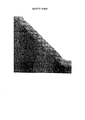
従来の補間カーネルの欠点は、主にピクセル値を使用して、補間ピクセルに対して水平および垂直方向から補間する点である。したがって、傾斜エッジを補間する場合は、そのエッジに沿ったピクセルではなく、主にそのエッジのどちらかの側にあるピクセル値が使用される。これにより、補間エッジはもはや滑らかではなく、ぎざぎざに表示される。これらの加工物は一般にジャギー(jaggy)と呼ばれる。図1では、(b),(c),(d)のそれぞれに、NN,双1次,および双3次の各補間カーネルについて示してあり、(a)に示す初期傾斜エッジに対してその拡大因数は8倍である。ジャギーは、NN補間法の場合が最も顕著であり、双1次補間法、双3次補間法の順に気にならなくなるのがわかる。ただし、双3次補間法の場合でも依然としてジャギーは顕著であり、ジャギー効果を減らすほどエッジのかすれ(特に双1次補間法で顕著な効果)は増大することがわかる。
【0007】
本発明の一目的は、以上のような1つまたは複数の従来技術の欠点を改善することであり、即ち、画像のエッジを補間する際に、ジャギーおよびかすれの両方を抑制することを目的とする。
【0008】
【課題を解決するための手段】
本発明の一態様によって提供される画像データを表示する画像処理方法は、以下の工程を備える。
【0009】
即ち、画像データを表示する画像処理方法であって、前記画像データの複数の離散サンプル値にアクセスする第1のステップと、前記離散サンプル値の方位角を決定する第2のステップと、前記離散サンプル値の方位角に応じて、複数の第1カーネルの1つを使用して前記それぞれの離散サンプル値についてカーネル値を計算する第3のステップと、前記画像データを表示するために、前記カーネル値を前記離散サンプル値でたたみ込む第4のステップと、を有し、前記第1カーネルは、第2カーネルを第1の方位角から第2の方位角まで回転させることによって構築されることを特徴とする。
【0010】
例えば、前記第1カーネルは下記形式からなり、
【0011】
【数19】

【0012】
また例えば、前記第1カーネルは下記形式からなり、
【0013】
【数20】
【0014】
また、本発明の別の態様によって提供される画像処理方法は、以下の工程を備える。
【0015】
即ち、第1のサンプルレートを有する画像の第1組の離散サンプル値を、第2のサンプルレートを有する前記画像の第2組の離散サンプル値に変換する画像処理方法であって、前記第1組の離散サンプル値にアクセスする第1のステップと、前記第1組の離散サンプル値に基づいて前記第2組の離散サンプル値のそれぞれを得る第2のステップと、を有し、該第2のステップは前記第2組の離散サンプル値毎に、前記第1組の離散サンプル値毎に方位角を決定するステップと、前記第1組の離散サンプル値毎に、その方位角に応じた複数の第1カーネルの1つに基づいてカーネル値を計算するステップと、前記カーネル値を前記第1組の前記離散サンプル値でたたみ込むステップと、を有し、前記第1カーネルは、第2カーネルを第1の方位角から第2の方位角まで回転させることによって構築されることを特徴とする。
【0016】
また、本発明の別の態様によって提供される画像処理方法は、以下の工程を備える。
【0017】
即ち、画像処理用の操向可能カーネルを生成する画像処理方法であって、画像処理のためにカーネルにアクセスする第1のステップと、操向可能カーネルを形成するために、前記カーネルを第1の方位角から第2の方位角まで回転する第2のステップと、該回転されたカーネルを記憶する第3のステップと、を有することを特徴とする。
【0018】
【発明の実施の形態】
本発明の実施形態では、特に傾斜エッジ上で、エッジのジャギー効果(jaggy effect)およびかすれ効果(blurring effect)の両方を減らす方法を開示する。
【0019】
以下、1つまたは複数の図面で、同じ参照番号が付けられたステップおよび/または特徴を参照している場合、これらのステップおよび/または特徴は、反対のものが示されない限り同じものを示す記述であるとする。
【0020】
1つの画像のエッジ領域内で補間を行う場合、エッジを横切るのではなくエッジに沿って滑らかに行うことが重要である。この方法によれば、エッジの輪郭は滑らかに保たれ、エッジの遷移は鮮鋭に保たれる。本発明の好適な実施形態では、かすれの程度を最小限に抑え、エッジを横切って環状になる一方で、エッジの長さに沿って高度な滑らかさを提供する2次元の補間カーネルを作成する方法を開示する。
【0021】
第1に、1次元の連続カーネルたたみ込みについて記載する。f(kΔt)(k=...−2,−1,0,1,2...)を連続関数f(t)のサンプルとし、ここでΔtはサンプル・レートである。連続カーネルを使用する補間法はf(t)の近似値である連続関数g(t)を与え、下記数式(1)に示す有限たたみ込み和によって得られる。
【0022】
【数21】
【0023】
【数22】
【0024】
従来の3次カーネルから2次元への拡張は、分割可能な拡張である。すなわち、たたみ込みカーネルを、以下に示す2つの方法のいずれか1つで画像データに適用することができる。
【0025】
(i)1次元たたみ込みカーネルを画像の行に適用し、次いでこれらの補間された値を使用して、画像の列に沿って補間する(あるいはその逆を行う)方法。たとえば、従来の3次カーネルには4つの係数があり、行および列の両方についても、最近隣の4つのサンプルが必要である。ただしこの技法には、補間された値の中間記憶装置が必要であるため、たとえばハードウェアの実装には不向きな場合があるという欠点がある。
【0026】
(ii)2次元カーネルを生成し、次いで画像データを使ってこれを直接たたみ込む方法。2次元カーネルは、行および列について別々に計算された係数値の行列乗法を使って生成される。たとえば、従来の双3次カーネルには16(4×4)の係数があり、双1次カーネルには4つ(2×2)の係数がある。次いでこれらの係数の2次元ブロックは、補間されるサンプル周辺にある最近隣初期画像ピクセルの同じサイズのブロックを使って、直接たたみ込みされる。この方法には、中間記憶装置がいっさい必要ないという利点があるが、より多くの乗法演算が必要である。さらにこの方法には、行および列で別々に実装されることのない、非分離可能カーネルを実装できるという利点もある。
【0027】
図2は、パラメータb=0、c=−0.5を使用した、従来の2次元3次カーネルのための輪郭プロットを示した図である。カーネルは第1に、補間されるピクセル(カーネルの中央になるはずである)に対して水平および垂直方向からピクセル値を使用することがわかる。言い換えれば、カーネルの任意の対角線からの係数値はほぼゼロであるため、この領域内にあるピクセル値は、数式(1)のたたみ込み和にほとんど影響を与えない。その結果、すでに論じた、図1に示されているジャギーおよびかすれの効果が得られる。
【0028】
特に明記しない限り、以下では、パラメータb=0を使用した3次カーネルの補間について説明する。水平エッジまたは垂直エッジの場合、cパラメータの様々な値を選択することで、それぞれの方向の様々な3次カーネルが効果的に使用される。たとえば、垂直エッジの補間に適したカーネルは、水平方向で値cx=0を、垂直方向で値cy=−0.5を使用した場合に得られる。このカーネルは、幅が2係数、高さが4係数であって、図4(c)に示す、方位=π/2(90°)のカーネルを有する。水平エッジの補間に適したカーネルは図4(a)に示されており、値cx=−0.5およびcy=0を使用して得られる。
【0029】
本発明の第1の実施形態は、水平(0)エッジおよび垂直(π/2)エッジだけでなく、45°(π/4)および135°(3π/4)の角度に向けることもできるエッジにも、補間カーネル(interpolation kernel)を利用する方法である。本発明の第2の実施形態は、エッジと同じ方位に、すなわち0からπまでの間の任意の角度で、正確に位置合わせができる、操向可能補間カーネル(steerable interpolation kernel)を開示する。πと2πの間のエッジ角度は、0とπの間の角度からπを減じた角度に等しく(たとえば、5π/4=5π/4−π=π/4)、あるいは0と−πの間のエッジ角度は、0とπの間の角度にπを加えた角度に等しい(たとえば、−π/4=−π/4+π=3π/4)。
【0030】
本発明の第1の実施形態(角度0,π/4,π/2,および3π/4にのみ操向可能)は第2の実施形態(完全に操向可能なカーネル)のサブセットであるが、第1の実施形態は十分な柔軟性をしばしば与えることが可能であり、完全に操向可能な方式に勝る利点がある。
【0031】
<第1実施形態>
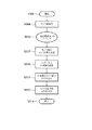
図3は、本発明の好適な実施形態による画像データの再サンプリング方法を示す流れ図である。この方法は、ステップS302から始まり、任意の必要なプロセスおよびパラメータが初期設定される。次のステップS304では、処理のためにf(kΔx,kΔy)(k=n...−2,−1,0,1,2,...n)の形式でサンプル値が取り出されるが、ここでΔxおよびΔyはそれぞれ水平および垂直のサンプリングレートである。プロセスはステップS306へ続き、ここでそれぞれの必要出力サンプル点(x,y)について、ステップS307〜S312が以下のように実行される。ステップS307では、補間されるエッジの強さおよび方位(θ)が決定される。次のステップS308では、好適な実施形態のカーネルに基づいて、カーネル値h(X−kΔx,Y−kΔy)が計算されるが、ここでh(sx,sy)は下記の数式(3)〜(6)によって得られる。
【0032】
【数23】
【0033】
【数24】
【0034】
以下に、好適な実施形態によるカーネルの詳細な説明について説明する。
【0035】
方位0およびπ/2は、従来の3次カーネルの分離可能拡張(separable extension)を使用して得られるが、パラメータ値はcx=0.5,cy=0およびcx=0.5,cy=0.5がそれぞれ使用される。方位π/4および3π/4は、2つの1次元3次カーネルをこれらの斜角方位で有効に計算し、次いで2次元カーネルを得るために行列乗法を使用することで得られる。したがって、水平および垂直方向の再サンプリング距離をそれぞれsxおよびsyで示す場合、それぞれ(sx+sy)/2および(sx−sy)/2を使用して、π/4および3π/4に垂直な1次平面に沿って係数値を計算することができる。追加の制約は、この係数の合計が1でなければならず(単位利得を与え直流リプルを発生させない)、フィルタは(エッジのかすれを最小限に抑えるために)エッジを横切ってほぼ2係数幅、すなわちエッジおよびゼロに対して反対角線の3係数である。したがって、方位π/4のカーネルを得るためには、入力距離(c=0.5)として(sx+sy)/2を使用して第1の3次カーネルを計算し、入力距離(c=0)として(sx−sy)/√2を使用して第2の3次カーネルを計算する。エッジを横切って補間する第2カーネルの場合のスケーリング差は、その幅をほぼ2係数に制限されているため、エッジのかすれが最小限に抑えられる。係数の合計を約1にするために、係数はそれぞれが掛け合わされた後に、1/√2でスケーリングされる。方位3π/4のカーネルを得るために、3次カーネルは、入力距離として(sx−sy)/2(c=0.5)および(sx+sy)/√2(c=0)を使用して計算され、再度1/√2でスケーリングされる。4つのカーネルはすべて、上記に定義されたとおりである。
【0036】
好適な実施形態のカーネルのメッシュプロットおよび輪郭プロットは、それぞれ図4および図5に示されている。図4および図5に示されているカーネルの方位は、カーネルの方位に垂直なエッジを補間するために使用されること、たとえば方位π/4のカーネルは、方位3π/4のエッジを補間するために使用されることに留意されたい。図1に示された初期傾斜エッジの拡大因数が8倍である場合の、開示された補間カーネルによる効果は、図6に実証される。図6では、エッジのジャギーおよびかすれの両方が著しく減じられることがわかる。
【0037】
第1の実施形態では、図7に示すように、回転するプレビット演算子(Prewitt operators)を使用してエッジの強さおよび方位が計算される。次いで、図7に示されたそれぞれのフィルタは、画像データおよび記憶された応答の大きさを使ってたたみ込まれる(係数が複数の方向に共通であることから、有効な方法で実行できる)。各ピクセルでのエッジ応答を使用して、それぞれの新しいサンプル点でどの補間カーネルを使用するかを決定する。すべてのエッジ検出器の応答の大きさが、あらかじめ設定されたしきい値よりも小さい場合、滑らかな部分になると考えられ、従来の3次カーネルが使用される。応答の大きさがあらかじめ設定されたしきい値よりも大きい場合、最大応答のエッジ方向を使用して、どの操向可能3次カーネルを使用するかを選択する。図11に、第1の実施形態のカーネル選択方法を定義する疑似コードを示す。
【0038】
いくつかのエッジ検出器を使用して、ロバーツまたはソーベル演算子(Roberts or Sobel operators)などの情報を得ることができる。さらに、ボルテラ・フィルタ(Volterra filter)またはローカル・ピクセル近傍で方向の同次性を測定する差異ベースのエッジ検出器など、いくつかの非線形エッジ検出器を使用することもできる。
【0039】
<第2実施形態>
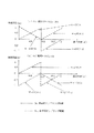
本発明の第2の実施形態は、操向可能カーネルを0からπの範囲で任意の角度まで拡張する方法を開示する。これは、操向角度θによって変わる再サンプリング距離、sxおよびsyの1次結合を利用して実行される。この場合、エッジに沿ったカーネルとエッジを横切るカーネルの2つの垂直カーネルに対して、sxおよびsyの両方について加重因数を計算する。図9は、本発明の第2の実施形態に使用される1次加重関数を示す図である。sxおよびsyの重さの絶対値の合計は1になるように制約されており、操向角0,π/4,π/2,および3π/4の場合にこれらの関数を使用して計算された加重因数は、第1の実施形態で使用される対応する加重因数に等しいことに留意されたい。本発明の第2の実施形態は、2つの垂直平面に沿って効果的に係数値を計算するが、1つはエッジ方向に沿ったいわゆるエッジ横付けカーネルを生成し、1つはエッジ方向に垂直のエッジ横断カーネルを生成する。第2の実施形態に追加された利点は、これらの平面が、0からπまでの範囲の任意の角度に向けることが可能であり、0からπまでの範囲の任意の角度で操向可能補間カーネルを生成するのに使用できるという点である。したがって、補間カーネルは、エッジがほぼローカルに線形である限り、すなわち、極端にカーブしていないかまたは2つのエッジの交差部分(コーナー)にある限り、エッジを任意の角度に適合させる。極端にカーブしているエッジやコーナーエッジが検出されると、両方の3次カーネルcxおよびcyのパラメータが0に等しくなるように、カーネルを変更することができる。この場合カーネルは、両方向でエッジ横断カーネルの形をとり、コーナーは保存される。このカーネルのメッシュプロットは図10に示してある。図12に、第2の実施形態のカーネル選択方法を定義する疑似コードを示す。
【0040】
第1の実施形態でも使用された残りのカーネルの設計制約は、エッジ横断カーネルが2係数幅になるということである。この制約に合致させるために、下記の数式(8),(9)に示すように、完全操向可能カーネル(fully steerable kernels)の定義において更に加重関数w(θ)が使用される。
【0041】
【数25】
エッジ横断加重因数w(θ)は、θ=0、π/2、およびπの場合には1を通過し、θ=π/4および3π/4の場合には√2を通過するように制約された、滑らかな関数である。この関数は、好適な実施形態で下記の数式(10)のように使用される。
【0043】
【数26】
数式(3),(4),(5),および(6)に開示された操向可能カーネルは、数式(8),(9),および(10)に開示された完全操向可能カーネルのサブセットであることがわかる。
【0045】
完全操向可能補間カーネルを適用するためには、入力画像の各ピクセル位置で、エッジの強さ(大きさ)およびエッジの角度の両方を計算する必要がある。これを実行するにはいくつかの周知の方法があるが、第2の実施形態では回転に相当する方向導関数カーネルが使用されるので最適である。これらのカーネルに関する詳細は、Hany Farid およびEero P Simoncelli共著「Optimally Rotation-equivalent Directional Derivative Kernels」(Proceedings of the 7th international Conference on Computer Analysis of Images and Patterns, Kiel, Germany, 1997年9月)を参照されたい。第2の実施形態で使用される係数は、下記のとおりである。
【0046】
【表1】
従来の技術で周知のように、これらの係数は別々に画像に適用され、垂直方向に次いで水平方向の順にエッジ強さを検出する。次に垂直方向および水平方向の応答の大きさを使用してエッジの強さを計算し、その割合の逆正接を使用してエッジ方位を計算する。
【0048】
操向可能3次曲線の第1の実施形態および第2の実施形態の両方で開示された式を使用すると、カーネルの直流利得はほぼ1になるだけであり、これはこのカーネルを使用して滑らかな領域を補間すると、明らかなリプル加工物が生じるということである。ただし、
1.開示された適応システムでは、π/4カーネルおよび3π/4カーネルは傾斜エッジの補間にのみ使用され、滑らかな領域には使用されないことと、
2.傾斜エッジを補間すると発生するどんなリプル効果もエッジによって効果的にマスクされるため、知覚される可視性は減少すること、
という理由から、問題にはならない。
【0049】
あるいは、係数を算出した後、単位利得を有するように正規化する、すなわち各係数に4×4ブロック内にある係数の和の逆数を掛けることができる。
【0050】
<装置の好適な実施形態>
本発明の好適な方法は、図8に示されているシステム800のような従来の汎用コンピュータシステムを使用して実行されることが好ましく、ここで図3から図7のプロセスはコンピュータ上でソフトウェアを実行しながら実装することができる。特に、この方法の各ステップは、コンピュータによって実行されるソフトウェア内の命令によって行われる。ソフトウェアは2つの別々の部分に分けることが可能であって、その1つは好適な実施形態の方法を実行し、もう1つは後者とユーザとの間のユーザインタフェースを管理する。ソフトウェアは、たとえば下記に記載された記憶デバイスを含む、コンピュータ可読媒体に格納することができる。ソフトウェアは、このコンピュータ可読媒体からコンピュータにロードされ、次いでコンピュータによって実行される。このようなソフトウェアを有するコンピュータ可読媒体またはその上に記録されたコンピュータプログラムが、コンピュータプログラム製品である。コンピュータ内でこのコンピュータプログラム製品を使用すると、本発明の実施形態により、エッジのジャギーやかすれの効果を減らすための有利な装置が実行される。
【0051】
コンピュータシステム800は、コンピュータモジュール802,ビデオディスプレイ816,および入力デバイス818,820を有する。さらにコンピュータシステム800は、ラインプリンタ,レーザプリンタ,プロッタ,ならびにコンピュータモジュール802に接続されたその他の再生デバイスを含む、任意数の他の出力デバイスを備えることができる。コンピュータシステム800は、モデム通信経路,コンピュータネットワーク等の適切な通信チャネル830を使用し、通信インターフェース808cを介して1つまたは複数の他のコンピュータに接続することができる。コンピュータネットワークは、ローカルエリアネットワーク(LAN),ワイドエリアネットワーク(WAN),イントラネット、および/またはインターネットを含むことができる。
【0052】
コンピュータモジュール802は、中央処理装置(以後簡単にプロセッサと呼ぶ)804,ランダムアクセスメモリ(RAM)およびリードオンリメモリ(ROM)を含むことのできるメモリ806,入出力(I/O)インタフェース808,ビデオインタフェース810,ならびに図8では一般にブロック812で表されている1つまたは複数の記憶デバイスを有する。記憶デバイス812は、当業者であれば周知の、フロッピィディスク,ハードディスクドライブ,磁気光学ディスクドライブ,CD−ROM,磁気テープ,あるいはその他任意数の不揮発性記憶デバイスの中から、1つまたは複数を含むことができる。一般に構成要素804から812までは、バス814を介してそれぞれ1つまたは複数の他のデバイスに接続され、さらにこれがデータバス,アドレスバス、およびコントロールバスを有する。
【0053】
ビデオインタフェース810はビデオディスプレイ816に接続され、コンピュータ802からのビデオ信号をビデオディスプレイ816上で表示するために提供する。コンピュータ802を動作させるためのユーザ入力は、1つまたは複数の入力デバイス808によって提供することができる。たとえばオペレータは、キーボード818および/またはマウス820などのポインティングデバイスを使用して、入力をコンピュータ802に提供することができる。
【0054】
システム800は単に例示のために示したものであり、本発明の範囲および精神を逸脱することがなければ、他の構成を使用することもできる。この実施形態を実施できる例示的コンピュータは、IBM−PCまたはその互換機,Macintosh(TM)のPC群のいずれか1つ,Sun Sparcstation(TM),及びそれらから発展した装置などを含む。以上、本発明の実施形態を実行するのに使用できるコンピュータの種類を、単に例示的に述べた。一般に、下記に記載する実施形態のプロセスは、コンピュータ可読媒体のようなハードディスクドライブ(図8では一般にブロック812として示す)上に記録されたソフトウェアまたはプログラムとして常駐しており、プロセッサ804を使用して読み取り、制御する。プログラムならびにピクセルデータおよびネットワークから取り込んだ任意のデータの中間記憶デバイスは、半導体メモリ806を使用し、おそらくはハードディスクドライブ812と組み合わせて実施することができる。
【0055】
場合によっては、プログラムをCD−ROMまたはフロッピィディスク(どちらも一般にブロック812で示す)上に符号化してユーザに供給することができるか、またはたとえば、コンピュータに接続されたモデムを介してユーザがネットワークから読み取ることができる。さらにまた、磁気テープ,ROMまたは集積回路,磁気光学ディスク,コンピュータと別の装置との間の無線または赤外線伝送チャネル,PCMCIAカードなどのコンピュータ読取り可能カード、ならびにEメール伝送およびウェブサイト上などに記録された情報を含むインターネットおよびイントラネットを含む、他のコンピュータ読み取り可能媒体から、コンピュータシステム800にソフトウェアをロードすることもできる。以上は、関連するコンピュータ可読媒体を例示的に示しただけである。本発明の範囲および精神を逸脱することがなければ、他のコンピュータ可読媒体を実施することができる。
【0056】
本発明の好適な方法は、この方法の各ステップの関数または副関数を実行する1つまたは複数の集積回路などの専用ハードウェアで実装することもできる。このような専用のハードウェアは、グラフィックプロセッサ,デジタル信号プロセッサ,または1つまたは複数のマイクロプロセッサおよび関連付けられたメモリを含むことができる。
【0057】
以上、本発明の一実施形態についてのみ記載したが、当業者であれば、本発明の範囲および精神を逸脱することなく、修正および/または変更を行うことができる。
【0058】
【発明の効果】
以上説明したように本発明によれば、画像のエッジを補間する場合に、ジャギーおよびかすれの両方を抑制することができる。
【図面の簡単な説明】
【図1】様々な補間カーネルを使用した際の、補間エッジ上のシャギー効果を示す図である。
【図2】パラメータb=0およびc=0.5で、従来の2次元カーネルを輪郭プロットした図である。
【図3】本発明の好適な実施形態によって、デジタルデータを補間する方法の流れ図である。
【図4】,第1の実施形態により、カーネルをメッシュ・プロットした図である。
【図5】第1の実施形態により、カーネルを輪郭プロットした図である。
【図6】図1と同じ入力で使用される、第1の実施形態の補間カーネルによる効果を示す図である。
【図7】好適な実施形態により、エッジの強さおよび向きを計算するために使用される、回転したプレビット演算子を示す図である。
【図8】好適な実施形態の方法が実施できる汎用コンピュータを示す図である。
【図9】本発明の第2の実施形態による、1次加重補間カーネルを示す図である。
【図10】図9のカーネルをメッシュ・プロットした図である。
【図11】本発明の第1の実施形態のカーネル選択方法を定義付ける、疑似コードを示す図である。
【図12】本発明の第2の実施形態のカーネル選択方法を定義付ける、疑似コードを示す図である。[0001]
BACKGROUND OF THE INVENTION
The present invention relates to an image processing method and apparatus for converting resolution in multidimensional image data and particularly digital image data. The invention also relates to a computer program comprising a computer readable medium having recorded thereon a computer program for resolution conversion in multidimensional image data and in particular digital image data.
[0002]
[Prior art]
Conventional continuous kernels for performing resolution conversion of digital data include a nearest neighbor kernel (hereinafter referred to as NN kernel), a primary, a secondary kernel, and a tertiary kernel.
[0003]
The NN kernel is the simplest interpolation method and simply interpolates the image using the pixel value spatially closest to the required value. This method is very effective when the magnification is an integral multiple of the initial data and a sharp edge is left without generating a new value, that is, a new color. However, other magnifications often cause obvious distortion in the output image, particularly images containing text or fine line details, and have the disadvantage of misalignment of the edge position.
[0004]
On the other hand, linear interpolation allows for the generation of new gray levels (or colors) that are effectively used in placing edges at sub-pixel locations. This has the advantage of reducing the effects caused by the shift of the edge position, but this time there is a possibility that a sharp edge will appear faint. Since the quadratic interpolation method and the cubic interpolation method provide a steeper step response than this, there is less blurring of the edge, but the response is steep so that overshoot occurs on either side of the edge. These overshoots may make the edges in the original image appear sharper, but are perceived because they are clearly visible in text, fine lines, or other computer-generated graphics. Impairs image quality and text readability.
[0005]
In conventional systems, kernels such as the nearest neighbor (NN) kernel, primary kernel, secondary kernel, tertiary kernel, etc. are first applied to the rows of the image, known as a separable implementation. This is often used either by subsequently applying to the column or by forming a two-dimensional kernel and convolving directly with the image data. These are called biprimary and bicubic implementations.
[0006]
[Problems to be solved by the invention]
A drawback of conventional interpolation kernels is that they interpolate horizontally and vertically with respect to the interpolated pixels, primarily using pixel values. Thus, when interpolating a slanted edge, pixel values that are primarily on either side of the edge are used, not the pixels along that edge. As a result, the interpolation edge is no longer smooth and is displayed in a jagged manner. These workpieces are commonly referred to as jaggy. In FIG. 1, (b), (c), and (d) show the NN, bilinear, and bicubic interpolation kernels, respectively, with respect to the initial slope edge shown in (a). The expansion factor is 8 times. Jaggy is most noticeable in the case of the NN interpolation method, and it can be seen that the jaggedness does not matter in the order of the bilinear interpolation method and the bicubic interpolation method. However, even in the case of the bicubic interpolation method, the jaggies are still remarkable, and it can be seen that the blurring of the edge (especially the effect of the bilinear interpolation method) increases as the jaggy effect is reduced.
[0007]
One object of the present invention is to ameliorate one or more of the disadvantages of the prior art, i.e., to suppress both jaggy and blurring when interpolating image edges. To do.
[0008]
[Means for Solving the Problems]
An image processing method for displaying image data provided by an aspect of the present invention includes the following steps.
[0009]
That is, an image processing method for displaying image data, the first step of accessing a plurality of discrete sample values of the image data, the second step of determining the azimuth angle of the discrete sample values, and the discrete A third step of calculating a kernel value for each of the discrete sample values using one of a plurality of first kernels depending on the azimuth of the sample value; and for displaying the image data, the kernel A fourth step of convolving a value with the discrete sample value, wherein the first kernel is constructed by rotating the second kernel from a first azimuth angle to a second azimuth angle. Features.
[0010]
For example, the first kernel has the following format:
[0011]
[Equation 19]
[0012]
For example, the first kernel has the following format:
[0013]
[Expression 20]
[0014]
An image processing method provided by another aspect of the present invention includes the following steps.
[0015]
That is, an image processing method for converting a first set of discrete sample values of an image having a first sample rate into a second set of discrete sample values of the image having a second sample rate, wherein the first set A first step of accessing a set of discrete sample values; and a second step of obtaining each of the second set of discrete sample values based on the first set of discrete sample values, the second step The step of determining an azimuth angle for each of the second set of discrete sample values and for each of the first set of discrete sample values, and a plurality of steps corresponding to the azimuth angle for each of the first set of discrete sample values. Computing a kernel value based on one of the first kernels, and convolving the kernel value with the first set of discrete sample values, wherein the first kernel is a second kernel The first orientation Characterized in that it is constructed by rotating the to the second azimuthal angle.
[0016]
An image processing method provided by another aspect of the present invention includes the following steps.
[0017]
That is, an image processing method for generating a steerable kernel for image processing, the first step of accessing the kernel for image processing, and the first kernel for forming a steerable kernel. A second step of rotating from the azimuth angle to a second azimuth angle, and a third step of storing the rotated kernel.
[0018]
DETAILED DESCRIPTION OF THE INVENTION
Embodiments of the present invention disclose a method for reducing both the jaggy and blurring effects of edges, particularly on sloping edges.
[0019]
Hereinafter, where one or more drawings refer to steps and / or features with the same reference number, these steps and / or features will be described to indicate the same unless the opposite is indicated. Suppose that
[0020]
When interpolation is performed within the edge region of one image, it is important that the interpolation is performed smoothly along the edge, not across the edge. According to this method, the edge contour is kept smooth, and the edge transition is kept sharp. The preferred embodiment of the present invention creates a two-dimensional interpolation kernel that minimizes the degree of blur and circularizes across the edge while providing a high degree of smoothness along the length of the edge. A method is disclosed.
[0021]
First, a one-dimensional continuous kernel convolution is described. Let f (kΔt) (k =... -2, −1, 0, 1, 2...) be a sample of the continuous function f (t), where Δt is the sample rate. An interpolation method using a continuous kernel gives a continuous function g (t) that is an approximate value of f (t), and is obtained by a finite convolution sum shown in the following equation (1).
[0022]
[Expression 21]
[0023]
[Expression 22]
[0024]
The conventional extension from the cubic kernel to the two dimensions is a divisible extension. That is, the convolution kernel can be applied to the image data by one of the following two methods.
[0025]
(I) A method of applying a one-dimensional convolution kernel to the rows of the image and then interpolating along the columns of the image using these interpolated values (or vice versa). For example, a conventional cubic kernel has four coefficients, and requires the nearest four samples for both rows and columns. However, this technique has the disadvantage that it requires an intermediate storage of interpolated values and may be unsuitable for hardware implementations, for example.
[0026]
(Ii) A method of generating a two-dimensional kernel and then convolving it directly with image data. Two-dimensional kernels are generated using matrix multiplication of coefficient values calculated separately for rows and columns. For example, a conventional bicubic kernel has 16 (4 × 4) coefficients, and a bilinear kernel has four (2 × 2) coefficients. The two-dimensional blocks of these coefficients are then convolved directly using the same size block of nearest-neighbor initial image pixels around the sample to be interpolated. This method has the advantage of not requiring any intermediate storage, but requires more multiplicative operations. This method also has the advantage of being able to implement a non-separable kernel that is not implemented separately in rows and columns.
[0027]
FIG. 2 shows a contour plot for a conventional two-dimensional cubic kernel using parameters b = 0 and c = −0.5. It can be seen that the kernel first uses pixel values from the horizontal and vertical directions for the interpolated pixel (which should be in the middle of the kernel). In other words, the coefficient values from any diagonal of the kernel are almost zero, so pixel values within this region have little effect on the convolution sum of equation (1). The result is the jaggy and blurring effect already discussed and shown in FIG.
[0028]
Unless specified otherwise, the following describes cubic kernel interpolation using the parameter b = 0. For horizontal or vertical edges, choosing different values of the c parameter effectively uses different cubic kernels in each direction. For example, a suitable kernel for vertical edge interpolation is the value c in the horizontal direction. x = 0, value c in the vertical direction y Obtained when = −0.5 is used. This kernel has a width of 2 coefficients, a height of 4 coefficients, and a kernel of orientation = π / 2 (90 °) shown in FIG. 4C. A suitable kernel for horizontal edge interpolation is shown in FIG. x = -0.5 and c y = 0.
[0029]
The first embodiment of the present invention is not only a horizontal (0) edge and a vertical (π / 2) edge, but also an edge that can be directed to 45 ° (π / 4) and 135 ° (3π / 4) angles Alternatively, an interpolation kernel is used. The second embodiment of the present invention discloses a steerable interpolation kernel that can be accurately aligned in the same orientation as the edges, ie, at any angle between 0 and π. The edge angle between π and 2π is equal to the angle between 0 and π minus π (eg, 5π / 4 = 5π / 4−π = π / 4), or between 0 and −π Is equal to the angle between 0 and π plus π (eg, −π / 4 = −π / 4 + π = 3π / 4).
[0030]
While the first embodiment of the present invention (which can be steered only at
[0031]
<First Embodiment>
FIG. 3 is a flowchart illustrating a method of resampling image data according to a preferred embodiment of the present invention. The method begins at step S302, where any necessary processes and parameters are initialized. In the next step S304, sample values are extracted in the form of f (kΔx, kΔy) (k = n... -2, −1, 0, 1, 2,... N) for processing. Here, Δx and Δy are horizontal and vertical sampling rates, respectively. The process continues to step S306 where steps S307-S312 are performed for each required output sample point (x, y) as follows. In step S307, the strength and direction (θ) of the edge to be interpolated are determined. In the next step S308, a kernel value h (X−kΔx, Y−kΔy) is calculated based on the kernel of the preferred embodiment, where h (sx, sy) Obtained by (6).
[0032]
[Expression 23]
[0033]
[Expression 24]
[0034]
In the following, a detailed description of the kernel according to the preferred embodiment will be described.
[0035]
The
[0036]
The kernel mesh and contour plots of the preferred embodiment are shown in FIGS. 4 and 5, respectively. The kernel orientation shown in FIGS. 4 and 5 is used to interpolate an edge perpendicular to the kernel orientation, eg, a kernel with orientation π / 4 interpolates an edge with orientation 3π / 4 Note that it is used for: The effect of the disclosed interpolation kernel when the initial slope edge expansion factor shown in FIG. 1 is 8 times is demonstrated in FIG. In FIG. 6, it can be seen that both edge jaggy and blurring are significantly reduced.
[0037]
In the first embodiment, as shown in FIG. 7, the strength and orientation of edges are calculated using rotating Prebitt operators. Each filter shown in FIG. 7 is then convolved with the image data and the stored response magnitude (can be performed in an effective manner since the coefficients are common to multiple directions). The edge response at each pixel is used to determine which interpolation kernel to use at each new sample point. If the magnitude of all edge detector responses is less than a preset threshold, a smooth portion is considered and a conventional cubic kernel is used. If the response magnitude is greater than a preset threshold, the edge direction of the maximum response is used to select which steerable cubic kernel to use. FIG. 11 shows pseudo code defining the kernel selection method of the first embodiment.
[0038]
Several edge detectors can be used to obtain information such as Roberts or Sobel operators. In addition, several non-linear edge detectors can be used, such as a Volterra filter or a difference-based edge detector that measures directional homogeneity near local pixels.
[0039]
Second Embodiment
The second embodiment of the present invention discloses a method for extending a steerable kernel to any angle in the range of 0 to π. This is the resampling distance that changes with the steering angle θ, s x And s y This is performed using a linear combination of In this case, for two vertical kernels, one along the edge and one across the edge, s x And s y Calculate weighted factors for both. FIG. 9 is a diagram showing a primary weighting function used in the second embodiment of the present invention. s x And s y The sum of the absolute values of the weights is constrained to be 1, and the weights calculated using these functions for steering
[0040]
The remaining kernel design constraint also used in the first embodiment is that the edge traversal kernel is two coefficient wide. To meet this constraint, a weighting function w (θ) is further used in the definition of fully steerable kernels, as shown in equations (8) and (9) below.
[0041]
[Expression 25]
The edge-to-edge weighting factor w (θ) is constrained to pass 1 when θ = 0, π / 2, and π, and to pass √2 when θ = π / 4 and 3π / 4. Is a smooth function. This function is used in the preferred embodiment as equation (10) below.
[0043]
[Equation 26]
The steerable kernel disclosed in equations (3), (4), (5), and (6) is the same as the fully steerable kernel disclosed in equations (8), (9), and (10). It turns out that it is a subset.
[0045]
To apply a fully steerable interpolation kernel, it is necessary to calculate both the edge strength (size) and the edge angle at each pixel location of the input image. There are several well-known ways to do this, but the second embodiment is optimal because a directional derivative kernel corresponding to rotation is used. For more details on these kernels, see "Optimally Rotation-equivalent Directional Derivative Kernels" by Hany Farid and Eero P Simoncelli (Proceedings of the 7th international Conference on Computer Analysis of Images and Patterns, Kiel, Germany, September 1997). I want. The coefficients used in the second embodiment are as follows.
[0046]
[Table 1]
As is well known in the prior art, these coefficients are applied separately to the image to detect edge strength in the order of vertical then horizontal. The magnitude of the response in the vertical and horizontal directions is then used to calculate the edge strength, and the arc tangent of that percentage is used to calculate the edge orientation.
[0048]
Using the equations disclosed in both the first and second embodiments of the steerable cubic curve, the dc gain of the kernel is only approximately 1, which is Interpolating a smooth area means that a clear ripple work is produced. However,
1. In the disclosed adaptive system, the π / 4 and 3π / 4 kernels are only used for slope edge interpolation, not for smooth regions;
2. Any ripple effect that occurs when interpolating a slanted edge is effectively masked by the edge, reducing the perceived visibility,
This is not a problem.
[0049]
Alternatively, after calculating the coefficients, they can be normalized to have unity gain, ie, each coefficient can be multiplied by the inverse of the sum of the coefficients in the 4 × 4 block.
[0050]
<Preferred Embodiment of Apparatus>
The preferred method of the present invention is preferably performed using a conventional general purpose computer system, such as the
[0051]
The
[0052]
The
[0053]
[0054]
[0055]
In some cases, the program can be provided to the user encoded on a CD-ROM or floppy disk (both generally indicated by block 812) or the user can network via a modem connected to a computer, for example. Can be read from. In addition, magnetic tape, ROM or integrated circuits, magneto-optical disks, wireless or infrared transmission channels between computers and other devices, computer readable cards such as PCMCIA cards, and e-mail transmission and recording on websites, etc. Software can also be loaded into
[0056]
The preferred method of the present invention can also be implemented in dedicated hardware such as one or more integrated circuits that perform the function or subfunction of each step of the method. Such dedicated hardware may include a graphics processor, digital signal processor, or one or more microprocessors and associated memory.
[0057]
Although only one embodiment of the present invention has been described above, those skilled in the art can make modifications and / or changes without departing from the scope and spirit of the present invention.
[0058]
【The invention's effect】
As described above, according to the present invention, it is possible to suppress both jaggy and blurring when interpolating the edge of an image.
[Brief description of the drawings]
FIG. 1 illustrates the shaggy effect on an interpolation edge when using various interpolation kernels.
FIG. 2 is a contour plot of a conventional two-dimensional kernel with parameters b = 0 and c = 0.5.
FIG. 3 is a flow diagram of a method for interpolating digital data according to a preferred embodiment of the present invention.
FIG. 4 is a diagram obtained by mesh plotting a kernel according to the first embodiment.
FIG. 5 is a contour plot of a kernel according to the first embodiment.
FIG. 6 is a diagram illustrating the effect of the interpolation kernel of the first embodiment, used with the same inputs as FIG. 1;
FIG. 7 illustrates a rotated prebit operator used to calculate edge strength and orientation, according to a preferred embodiment.
FIG. 8 illustrates a general purpose computer capable of implementing the method of the preferred embodiment.
FIG. 9 shows a primary weighted interpolation kernel according to a second embodiment of the present invention.
10 is a mesh plot of the kernel of FIG.
FIG. 11 is a diagram illustrating pseudo code defining a kernel selection method according to the first embodiment of this invention;
FIG. 12 is a diagram illustrating pseudo code defining a kernel selection method according to the second embodiment of this invention;
Claims (48)
前記画像データの複数の離散サンプル値にアクセスする第1のステップと、
前記離散サンプル値の方位角を決定する第2のステップと、
前記離散サンプル値の方位角に応じて、複数の第1カーネルの1つを使用して前記それぞれの離散サンプル値についてカーネル値を計算する第3のステップと、
前記画像データを表示するために、前記カーネル値を前記離散サンプル値でたたみ込む第4のステップと、
を有し、前記第1カーネルは、第2カーネルを第1の方位角から第2の方位角まで回転させることによって構築されることを特徴とする画像処理方法。An image processing method for displaying image data,
A first step of accessing a plurality of discrete sample values of the image data;
A second step of determining an azimuth angle of the discrete sample value;
A third step of calculating a kernel value for each discrete sample value using one of a plurality of first kernels, depending on the azimuth of the discrete sample value;
A fourth step of convolving the kernel values with the discrete sample values to display the image data;
And the first kernel is constructed by rotating the second kernel from a first azimuth angle to a second azimuth angle.
を有することを特徴とする請求項1記載の画像処理方法。And convolving each of the filtered sample values with at least one other kernel to generate a second set of filtered sample values;
The image processing method according to claim 1, further comprising:
前記画像データの複数の離散サンプル値にアクセスするアクセス手段と、
前記離散サンプル値の方位角を決定する方位角決定手段と、
前記離散サンプル値の方位角に応じて、複数の第1カーネルの1つを使用して前記それぞれの離散サンプル値についてカーネル値を計算する計算手段と、
前記画像データを表示するために、前記カーネル値を前記離散サンプル値でたたみ込むたたみ込み手段と、
を有し、前記第1カーネルは、第2カーネルを第1の方位角から第2の方位角まで回転させることによって構築されることを特徴とする画像処理装置。An image processing apparatus for displaying image data,
Access means for accessing a plurality of discrete sample values of the image data;
Azimuth angle determining means for determining an azimuth angle of the discrete sample value;
Calculating means for calculating a kernel value for each discrete sample value using one of a plurality of first kernels according to the azimuth of the discrete sample value;
Convolution means for convolving the kernel values with the discrete sample values to display the image data;
And the first kernel is constructed by rotating the second kernel from a first azimuth angle to a second azimuth angle.
前記画像データの複数の離散サンプル値にアクセスするコードと、
前記離散サンプル値の方位角を決定するコードと、
前記離散サンプル値の方位角に応じて、複数の第1カーネルの1つを使用して前記それぞれの離散サンプル値についてカーネル値を計算するコードと、
前記画像データを表示するために、前記カーネル値を前記離散サンプル値でたたみ込むコードと、
を有し、前記第1カーネルは、第2カーネルを第1の方位角から第2の方位角まで回転させることによって構築されることを特徴とするコンピュータ可読媒体。A computer-readable medium storing a program executed by an apparatus that performs data processing including a display method of image data, the program comprising:
A code for accessing a plurality of discrete sample values of the image data;
A code for determining an azimuth angle of the discrete sample value;
Code for calculating a kernel value for each discrete sample value using one of a plurality of first kernels, depending on the azimuth of the discrete sample value;
A code for convolving the kernel value with the discrete sample value to display the image data;
And the first kernel is constructed by rotating the second kernel from a first azimuth angle to a second azimuth angle.
前記画像データの複数の離散サンプル値にアクセスする第1のステップと、
前記離散サンプル値の方位角を決定する第2のステップと、
前記離散サンプル値の方位角に応じて、複数の第1カーネルの1つを使用して前記それぞれの離散サンプル値についてカーネル値を計算する第3のステップと、
前記画像データを表示するために、前記カーネル値を前記離散サンプル値でたたみ込む第4のステップと、
を有し、前記第1カーネルは、第2カーネルを第1の方位角から第2の方位角まで回転させることによって下記形式で構築され、
A first step of accessing a plurality of discrete sample values of the image data;
A second step of determining an azimuth angle of the discrete sample value;
A third step of calculating a kernel value for each discrete sample value using one of a plurality of first kernels, depending on the azimuth of the discrete sample value;
A fourth step of convolving the kernel values with the discrete sample values to display the image data;
And the first kernel is constructed in the following form by rotating the second kernel from a first azimuth to a second azimuth:
前記画像データの複数の離散サンプル値にアクセスするアクセス手段と、
前記離散サンプル値の方位角を決定する方位角決定手段と、
前記離散サンプル値の方位角に応じて、複数の第1カーネルの1つを使用して前記それぞれの離散サンプル値についてカーネル値を計算する計算手段と、
前記画像データを表示するために、前記カーネル値を前記離散サンプル値でたたみ込むたたみ込み手段と、
を有し、前記第1カーネルは、第2カーネルを第1の方位角から第2の方位角まで回転させることによって下記形式で構築され、
Access means for accessing a plurality of discrete sample values of the image data;
Azimuth angle determining means for determining an azimuth angle of the discrete sample value;
Calculating means for calculating a kernel value for each discrete sample value using one of a plurality of first kernels according to the azimuth of the discrete sample value;
Convolution means for convolving the kernel values with the discrete sample values to display the image data;
And the first kernel is constructed in the following form by rotating the second kernel from a first azimuth to a second azimuth:
前記画像データの複数の離散サンプル値にアクセスするコードと、
前記離散サンプル値の方位角を決定するコードと、
前記離散サンプル値の方位角に応じて、複数の第1カーネルの1つを使用して前記それぞれの離散サンプル値についてカーネル値を計算するコードと、
前記画像データを表示するために、前記カーネル値を前記離散サンプル値でたたみ込むコードと、
を有し、前記第1カーネルは、第2カーネルを第1の方位角から第2の方位角まで回転させることによって下記形式で構築され、
A code for accessing a plurality of discrete sample values of the image data;
A code for determining an azimuth angle of the discrete sample value;
Code for calculating a kernel value for each discrete sample value using one of a plurality of first kernels, depending on the azimuth of the discrete sample value;
A code for convolving the kernel value with the discrete sample value to display the image data;
And the first kernel is constructed in the following form by rotating the second kernel from a first azimuth to a second azimuth:
前記第1組の離散サンプル値にアクセスする第1のステップと、
前記第1組の離散サンプル値に基づいて前記第2組の離散サンプル値のそれぞれを得る第2のステップと、
を有し、該第2のステップは前記第2組の離散サンプル値毎に、前記第1組の離散サンプル値毎に方位角を決定するステップと、
前記第1組の離散サンプル値毎に、その方位角に応じた複数の第1カーネルの1つに基づいてカーネル値を計算するステップと、
前記カーネル値を前記第1組の前記離散サンプル値でたたみ込むステップと、
を有し、前記第1カーネルは、第2カーネルを第1の方位角から第2の方位角まで回転させることによって構築されることを特徴とする画像処理方法。An image processing method for converting a first set of discrete sample values of an image having a first sample rate into a second set of discrete sample values of the image having a second sample rate, comprising:
A first step of accessing the first set of discrete sample values;
A second step of obtaining each of the second set of discrete sample values based on the first set of discrete sample values;
The second step includes determining an azimuth for each of the second set of discrete sample values and for each of the first set of discrete sample values;
For each of the first set of discrete sample values, calculating a kernel value based on one of a plurality of first kernels corresponding to the azimuth angle;
Convolving the kernel value with the first set of discrete sample values;
And the first kernel is constructed by rotating the second kernel from a first azimuth angle to a second azimuth angle.
前記第1組の離散サンプル値にアクセスするアクセス手段と、
前記第1組の離散サンプル値に基づいて前記第2組の離散サンプル値のそれぞれを得る処理手段と、
を有し、
該処理手段は前記第2組の離散サンプル値毎に、前記第1組の離散サンプル値毎に方位角を決定する処理と、
前記第1組の離散サンプル値毎に、その方位角に応じた複数の第1カーネルの1つに基づいてカーネル値を計算する処理と、
前記カーネル値を前記第1組の前記離散サンプル値でたたみ込む処理と、
を実行し、前記第1カーネルは、第2カーネルを第1の方位角から第2の方位角まで回転させることによって構築されることを特徴とする画像処理装置。An image processing device for converting a first set of discrete sample values of an image having a first sample rate into a second set of discrete sample values of the image having a second sample rate,
Access means for accessing the first set of discrete sample values;
Processing means for obtaining each of the second set of discrete sample values based on the first set of discrete sample values;
Have
The processing means determines the azimuth for each of the second set of discrete sample values and for each of the first set of discrete sample values;
Calculating a kernel value based on one of a plurality of first kernels corresponding to the azimuth angle for each of the first set of discrete sample values;
A process of convolving the kernel value with the first set of discrete sample values;
And the first kernel is constructed by rotating the second kernel from a first azimuth angle to a second azimuth angle.
前記第1組の離散サンプル値にアクセスする第1のコードと、
前記第1組の離散サンプル値に基づいて前記第2組の離散サンプル値のそれぞれを得る第2のコードと、
を有し、該第2のコードは前記第2組の離散サンプル値毎に、前記第1組の離散サンプル値毎に方位角を決定するコードと、
前記第1組の離散サンプル値毎に、その方位角に応じた複数の第1カーネルの1つに基づいてカーネル値を計算するコードと、
前記カーネル値を前記第1組の前記離散サンプル値でたたみ込むコードと、
を有し、前記第1カーネルは、第2カーネルを第1の方位角から第2の方位角まで回転させることによって構築されることを特徴とするコンピュータ可読媒体。Executed in an apparatus for performing data processing including image processing for converting a first set of discrete sample values of an image having a first sample rate into a second set of discrete sample values of the image having a second sample rate. A computer readable medium storing a program, the program comprising:
A first code for accessing the first set of discrete sample values;
A second code for obtaining each of the second set of discrete sample values based on the first set of discrete sample values;
The second code for each of the second set of discrete sample values, a code for determining an azimuth for each of the first set of discrete sample values;
A code for calculating a kernel value based on one of a plurality of first kernels corresponding to the azimuth for each of the first set of discrete sample values;
Code for convolving the kernel value with the first set of discrete sample values;
And the first kernel is constructed by rotating the second kernel from a first azimuth angle to a second azimuth angle.
画像処理のためにカーネルにアクセスする第1のステップと、
操向可能カーネルを形成するために、前記カーネルを第1の方位角から第2の方位角まで回転する第2のステップと、
該回転されたカーネルを記憶する第3のステップと、
を有することを特徴とする画像処理方法。An image processing method for generating a steerable kernel for image processing,
A first step of accessing the kernel for image processing;
Rotating the kernel from a first azimuth angle to a second azimuth angle to form a steerable kernel;
A third step of storing the rotated kernel;
An image processing method comprising:
Applications Claiming Priority (2)
| Application Number | Priority Date | Filing Date | Title |
|---|---|---|---|
| AU7802 | 1997-07-09 | ||
| AUPP7802A AUPP780298A0 (en) | 1998-12-18 | 1998-12-18 | A steerable kernel for image interpolation |
Publications (3)
| Publication Number | Publication Date |
|---|---|
| JP2000182039A JP2000182039A (en) | 2000-06-30 |
| JP2000182039A5 JP2000182039A5 (en) | 2005-07-21 |
| JP3890174B2 true JP3890174B2 (en) | 2007-03-07 |
Family
ID=3812006
Family Applications (1)
| Application Number | Title | Priority Date | Filing Date |
|---|---|---|---|
| JP36176499A Expired - Fee Related JP3890174B2 (en) | 1998-12-18 | 1999-12-20 | Image processing method, image processing apparatus, and computer-readable medium |
Country Status (3)
| Country | Link |
|---|---|
| US (1) | US6748120B1 (en) |
| JP (1) | JP3890174B2 (en) |
| AU (1) | AUPP780298A0 (en) |
Families Citing this family (15)
| Publication number | Priority date | Publication date | Assignee | Title |
|---|---|---|---|---|
| US6816622B2 (en) * | 2001-10-18 | 2004-11-09 | Microsoft Corporation | Generating resized images using ripple free image filtering |
| FR2841487B1 (en) * | 2002-06-26 | 2004-08-20 | Solystic | METHOD FOR DETECTING SINGLE PLIERS AND MULTIPLE PLUG PLUGS IN A POSTAL SORTING FACILITY |
| US7409056B2 (en) * | 2002-12-16 | 2008-08-05 | Broadcom Corporation | Switchboard for dual-rate single-band communication system |
| US7525526B2 (en) * | 2003-10-28 | 2009-04-28 | Samsung Electronics Co., Ltd. | System and method for performing image reconstruction and subpixel rendering to effect scaling for multi-mode display |
| KR100562937B1 (en) * | 2004-08-11 | 2006-03-22 | 엘지전자 주식회사 | Method and Apparatus for Processing Image of Display Device |
| US7636489B2 (en) * | 2004-04-16 | 2009-12-22 | Apple Inc. | Blur computation algorithm |
| US20060013504A1 (en) * | 2004-07-15 | 2006-01-19 | Edge Medical Devices Ltd. | Multi-resolution image enhancement |
| CN100585620C (en) * | 2004-08-20 | 2010-01-27 | 奥普提克斯晶硅有限公司 | Edge adaptive image expansion and enhancement system and method |
| KR100643305B1 (en) * | 2005-02-14 | 2006-11-10 | 삼성전자주식회사 | Method and apparatus for processing line pattern using convolution kernel |
| JP2006238188A (en) * | 2005-02-25 | 2006-09-07 | Matsushita Electric Ind Co Ltd | Interpolation filter and video signal processing device |
| US7519235B1 (en) | 2005-10-24 | 2009-04-14 | Adobe Systems Incorporated | Using nonlinear filtering while resizing an image to preserve sharp image detail |
| JP4539886B2 (en) * | 2007-08-20 | 2010-09-08 | セイコーエプソン株式会社 | Image processing system, projector, program, and information storage medium |
| CN101639932B (en) * | 2008-07-28 | 2011-10-12 | 汉王科技股份有限公司 | Method and system for enhancing digital image resolution |
| JP5617426B2 (en) * | 2010-08-16 | 2014-11-05 | 大日本印刷株式会社 | Jaggy mitigation processing apparatus and jaggy mitigation processing method |
| CN104574277A (en) * | 2015-01-30 | 2015-04-29 | 京东方科技集团股份有限公司 | Image interpolation method and image interpolation device |
Family Cites Families (2)
| Publication number | Priority date | Publication date | Assignee | Title |
|---|---|---|---|---|
| US5054100A (en) * | 1989-11-16 | 1991-10-01 | Eastman Kodak Company | Pixel interpolator with edge sharpening |
| US5131057A (en) * | 1990-02-12 | 1992-07-14 | Wright State University | Method for video-to-printing image resolution conversion |
-
1998
- 1998-12-18 AU AUPP7802A patent/AUPP780298A0/en not_active Abandoned
-
1999
- 1999-12-15 US US09/461,054 patent/US6748120B1/en not_active Expired - Fee Related
- 1999-12-20 JP JP36176499A patent/JP3890174B2/en not_active Expired - Fee Related
Also Published As
| Publication number | Publication date |
|---|---|
| US6748120B1 (en) | 2004-06-08 |
| JP2000182039A (en) | 2000-06-30 |
| AUPP780298A0 (en) | 1999-01-21 |
Similar Documents
| Publication | Publication Date | Title |
|---|---|---|
| JP3890175B2 (en) | Image processing method and apparatus | |
| JP3890174B2 (en) | Image processing method, image processing apparatus, and computer-readable medium | |
| US6407747B1 (en) | Computer screen image magnification system and method | |
| US6411305B1 (en) | Image magnification and selective image sharpening system and method | |
| US7149369B2 (en) | Method and system for image scaling | |
| EP2239705B1 (en) | Resizing images of an image sequence | |
| Wei et al. | Contrast-guided image interpolation | |
| US7043091B2 (en) | Method and apparatus for increasing spatial resolution of an image | |
| US6381375B1 (en) | Methods and apparatus for generating a projection of an image | |
| US7817871B2 (en) | Scaling of raster images without blurring of edges | |
| US6727908B1 (en) | Non-linear interpolation scaling system for a graphics processing system and method for use thereof | |
| US20040086201A1 (en) | Fast edge directed polynomial interpolation | |
| US6714210B1 (en) | Continuous kernel image interpolation | |
| JP2008263465A (en) | Image processing system and image processing program | |
| EP0814429A2 (en) | An image processing system | |
| WO2000075865A1 (en) | Image processing method | |
| US6687417B1 (en) | Modified kernel for image interpolation | |
| US7428346B2 (en) | Image processing method and image processing device | |
| AU745082B2 (en) | A steerable kernel for image interpolation | |
| AU745562B2 (en) | A method of kernel selection for image interpolation | |
| AU2007249113A1 (en) | Orientation adapted aliasing cancellation | |
| Joshi et al. | Fast edge-filtered image upsampling | |
| AU730522B1 (en) | Continuous kernel image interpolation | |
| AU736359B2 (en) | Image interpolation with a continuous 2-dimensional kernel | |
| AU729482B2 (en) | Image interpolation with a continuous two-dimensional kernel |
Legal Events
| Date | Code | Title | Description |
|---|---|---|---|
| A521 | Request for written amendment filed |
Free format text: JAPANESE INTERMEDIATE CODE: A523 Effective date: 20041208 |
|
| A621 | Written request for application examination |
Free format text: JAPANESE INTERMEDIATE CODE: A621 Effective date: 20041208 |
|
| RD01 | Notification of change of attorney |
Free format text: JAPANESE INTERMEDIATE CODE: A7426 Effective date: 20041208 |
|
| RD03 | Notification of appointment of power of attorney |
Free format text: JAPANESE INTERMEDIATE CODE: A7423 Effective date: 20041208 |
|
| TRDD | Decision of grant or rejection written | ||
| A01 | Written decision to grant a patent or to grant a registration (utility model) |
Free format text: JAPANESE INTERMEDIATE CODE: A01 Effective date: 20061120 |
|
| A61 | First payment of annual fees (during grant procedure) |
Free format text: JAPANESE INTERMEDIATE CODE: A61 Effective date: 20061204 |
|
| R150 | Certificate of patent or registration of utility model |
Free format text: JAPANESE INTERMEDIATE CODE: R150 |
|
| FPAY | Renewal fee payment (event date is renewal date of database) |
Free format text: PAYMENT UNTIL: 20091208 Year of fee payment: 3 |
|
| FPAY | Renewal fee payment (event date is renewal date of database) |
Free format text: PAYMENT UNTIL: 20101208 Year of fee payment: 4 |
|
| FPAY | Renewal fee payment (event date is renewal date of database) |
Free format text: PAYMENT UNTIL: 20111208 Year of fee payment: 5 |
|
| FPAY | Renewal fee payment (event date is renewal date of database) |
Free format text: PAYMENT UNTIL: 20121208 Year of fee payment: 6 |
|
| FPAY | Renewal fee payment (event date is renewal date of database) |
Free format text: PAYMENT UNTIL: 20131208 Year of fee payment: 7 |
|
| S802 | Written request for registration of partial abandonment of right |
Free format text: JAPANESE INTERMEDIATE CODE: R311802 |
|
| R350 | Written notification of registration of transfer |
Free format text: JAPANESE INTERMEDIATE CODE: R350 |
|
| LAPS | Cancellation because of no payment of annual fees |