JP3887635B2 - Independent power system - Google Patents
Independent power system Download PDFInfo
- Publication number
- JP3887635B2 JP3887635B2 JP2004262833A JP2004262833A JP3887635B2 JP 3887635 B2 JP3887635 B2 JP 3887635B2 JP 2004262833 A JP2004262833 A JP 2004262833A JP 2004262833 A JP2004262833 A JP 2004262833A JP 3887635 B2 JP3887635 B2 JP 3887635B2
- Authority
- JP
- Japan
- Prior art keywords
- storage battery
- power supply
- supply system
- voltage
- independent power
- Prior art date
- Legal status (The legal status is an assumption and is not a legal conclusion. Google has not performed a legal analysis and makes no representation as to the accuracy of the status listed.)
- Expired - Fee Related
Links
- 238000003860 storage Methods 0.000 claims description 259
- 230000004044 response Effects 0.000 claims description 12
- 238000007599 discharging Methods 0.000 claims description 11
- 238000006243 chemical reaction Methods 0.000 claims description 2
- 238000001514 detection method Methods 0.000 claims description 2
- 229910052987 metal hydride Inorganic materials 0.000 claims description 2
- 239000003990 capacitor Substances 0.000 description 16
- 238000010586 diagram Methods 0.000 description 10
- 230000002457 bidirectional effect Effects 0.000 description 4
- 238000010248 power generation Methods 0.000 description 4
- 230000019635 sulfation Effects 0.000 description 3
- 238000005670 sulfation reaction Methods 0.000 description 3
- CURLTUGMZLYLDI-UHFFFAOYSA-N Carbon dioxide Chemical compound O=C=O CURLTUGMZLYLDI-UHFFFAOYSA-N 0.000 description 2
- 230000004913 activation Effects 0.000 description 2
- 229910021417 amorphous silicon Inorganic materials 0.000 description 2
- 239000000446 fuel Substances 0.000 description 2
- PIJPYDMVFNTHIP-UHFFFAOYSA-L lead sulfate Chemical compound [PbH4+2].[O-]S([O-])(=O)=O PIJPYDMVFNTHIP-UHFFFAOYSA-L 0.000 description 2
- 238000000034 method Methods 0.000 description 2
- 230000002265 prevention Effects 0.000 description 2
- HBBGRARXTFLTSG-UHFFFAOYSA-N Lithium ion Chemical compound [Li+] HBBGRARXTFLTSG-UHFFFAOYSA-N 0.000 description 1
- 238000009825 accumulation Methods 0.000 description 1
- 229910002092 carbon dioxide Inorganic materials 0.000 description 1
- 239000001569 carbon dioxide Substances 0.000 description 1
- 230000008859 change Effects 0.000 description 1
- 230000000295 complement effect Effects 0.000 description 1
- 150000001875 compounds Chemical class 0.000 description 1
- 229910021419 crystalline silicon Inorganic materials 0.000 description 1
- 230000007423 decrease Effects 0.000 description 1
- 230000007613 environmental effect Effects 0.000 description 1
- 238000009434 installation Methods 0.000 description 1
- 229910001416 lithium ion Inorganic materials 0.000 description 1
- 238000004519 manufacturing process Methods 0.000 description 1
- 230000004048 modification Effects 0.000 description 1
- 238000012986 modification Methods 0.000 description 1
- 229910052759 nickel Inorganic materials 0.000 description 1
- PXHVJJICTQNCMI-UHFFFAOYSA-N nickel Substances [Ni] PXHVJJICTQNCMI-UHFFFAOYSA-N 0.000 description 1
- -1 nickel metal hydride Chemical class 0.000 description 1
- 230000008569 process Effects 0.000 description 1
- 239000004065 semiconductor Substances 0.000 description 1
- 238000004904 shortening Methods 0.000 description 1
- 239000000758 substrate Substances 0.000 description 1
- 239000010409 thin film Substances 0.000 description 1
- 238000010792 warming Methods 0.000 description 1
Images


Classifications
-
- H—ELECTRICITY
- H02—GENERATION; CONVERSION OR DISTRIBUTION OF ELECTRIC POWER
- H02J—CIRCUIT ARRANGEMENTS OR SYSTEMS FOR SUPPLYING OR DISTRIBUTING ELECTRIC POWER; SYSTEMS FOR STORING ELECTRIC ENERGY
- H02J7/00—Circuit arrangements for charging or depolarising batteries or for supplying loads from batteries
- H02J7/0013—Circuit arrangements for charging or depolarising batteries or for supplying loads from batteries acting upon several batteries simultaneously or sequentially
- H02J7/0014—Circuits for equalisation of charge between batteries
- H02J7/0019—Circuits for equalisation of charge between batteries using switched or multiplexed charge circuits
-
- H—ELECTRICITY
- H02—GENERATION; CONVERSION OR DISTRIBUTION OF ELECTRIC POWER
- H02J—CIRCUIT ARRANGEMENTS OR SYSTEMS FOR SUPPLYING OR DISTRIBUTING ELECTRIC POWER; SYSTEMS FOR STORING ELECTRIC ENERGY
- H02J7/00—Circuit arrangements for charging or depolarising batteries or for supplying loads from batteries
- H02J7/0013—Circuit arrangements for charging or depolarising batteries or for supplying loads from batteries acting upon several batteries simultaneously or sequentially
- H02J7/0025—Sequential battery discharge in systems with a plurality of batteries
-
- H—ELECTRICITY
- H02—GENERATION; CONVERSION OR DISTRIBUTION OF ELECTRIC POWER
- H02J—CIRCUIT ARRANGEMENTS OR SYSTEMS FOR SUPPLYING OR DISTRIBUTING ELECTRIC POWER; SYSTEMS FOR STORING ELECTRIC ENERGY
- H02J7/00—Circuit arrangements for charging or depolarising batteries or for supplying loads from batteries
- H02J7/34—Parallel operation in networks using both storage and other dc sources, e.g. providing buffering
- H02J7/35—Parallel operation in networks using both storage and other dc sources, e.g. providing buffering with light sensitive cells
-
- H—ELECTRICITY
- H02—GENERATION; CONVERSION OR DISTRIBUTION OF ELECTRIC POWER
- H02J—CIRCUIT ARRANGEMENTS OR SYSTEMS FOR SUPPLYING OR DISTRIBUTING ELECTRIC POWER; SYSTEMS FOR STORING ELECTRIC ENERGY
- H02J2207/00—Indexing scheme relating to details of circuit arrangements for charging or depolarising batteries or for supplying loads from batteries
- H02J2207/20—Charging or discharging characterised by the power electronics converter
-
- Y—GENERAL TAGGING OF NEW TECHNOLOGICAL DEVELOPMENTS; GENERAL TAGGING OF CROSS-SECTIONAL TECHNOLOGIES SPANNING OVER SEVERAL SECTIONS OF THE IPC; TECHNICAL SUBJECTS COVERED BY FORMER USPC CROSS-REFERENCE ART COLLECTIONS [XRACs] AND DIGESTS
- Y02—TECHNOLOGIES OR APPLICATIONS FOR MITIGATION OR ADAPTATION AGAINST CLIMATE CHANGE
- Y02E—REDUCTION OF GREENHOUSE GAS [GHG] EMISSIONS, RELATED TO ENERGY GENERATION, TRANSMISSION OR DISTRIBUTION
- Y02E10/00—Energy generation through renewable energy sources
- Y02E10/50—Photovoltaic [PV] energy
- Y02E10/56—Power conversion systems, e.g. maximum power point trackers
Description
この発明は、独立電源システムに関し、より特定的には、電気機器に電力を供給する小規模独立電源システムに関する。 The present invention relates to an independent power supply system, and more particularly, to a small-scale independent power supply system that supplies electric power to an electrical device.
太陽電池は、太陽光エネルギーを直接電気エネルギーに変換するものであり、近年の地球環境問題に対する意識の高まりを背景に、地球温暖化の原因とされる二酸化炭素を排出しないクリーンな発電装置として注目されている。 Solar cells convert solar energy directly into electrical energy, and are attracting attention as a clean power generator that does not emit carbon dioxide, which is a cause of global warming, against the background of increasing awareness of global environmental issues in recent years. Has been.
しかしながら、太陽電池は、出力する電力が照度に依存して一定ではないことから、電力を安定供給するために、太陽電池と蓄電池とを組み合わせて、蓄電池に太陽電池の発電電力を蓄える構成とした独立電源システムが広く用いられている。 However, since the output power of the solar battery is not constant depending on the illuminance, the solar battery and the storage battery are combined to store the generated power of the solar battery in the storage battery in order to stably supply the power. Independent power supply systems are widely used.
従来の独立電源システムは、図示は省略するが、太陽電池と、太陽電池から出力される直流電力を蓄積する蓄電池と、蓄電池から出力される直流電力を交流電力に変換するインバータユニットとを備える。 Although not shown, the conventional independent power supply system includes a solar cell, a storage battery that stores DC power output from the solar battery, and an inverter unit that converts DC power output from the storage battery into AC power.
本構成において、太陽電池で発生した電流は、蓄電池あるいは負荷へと流れる。蓄電池は、負荷が変動して太陽電池の出力で賄いきれないとき、あるいは夜間のように太陽電池が発電していないときには放電し、逆に負荷が小さく、太陽電池の出力に余裕ができたときには充電するというように、負荷に対する調整を行なうものである。なお、蓄電池には、消耗したときに容易に交換できるように、汎用の鉛蓄電池が用いられる。 In this configuration, the current generated in the solar cell flows to the storage battery or the load. A storage battery discharges when the load fluctuates and cannot be covered by the output of the solar cell, or when the solar cell is not generating power, such as at night, and conversely, when the load is small and there is room in the output of the solar cell Adjustment is made for the load such as charging. In addition, a general-purpose lead storage battery is used for the storage battery so that it can be easily replaced when exhausted.
インバータユニットには、交流電気負荷が並列に結合される。交流電気負荷は、インバータユニットの出力する交流電力により動作する。 An AC electric load is coupled in parallel to the inverter unit. The AC electric load is operated by AC power output from the inverter unit.
このような構成とすることにより、従来の独立電源システムは、照度の変化に関わらず、負荷に対して安定的に電力を供給することができる。一方、システムに搭載される鉛蓄電池においては、天候不良による充電不足状態が続いたときなどに、負極板に不活性な硫酸鉛が蓄積する、いわゆるサルフェーションが発生し、容量が低下して寿命が短くなってしまうという問題が生じていた。 With such a configuration, the conventional independent power supply system can stably supply power to the load regardless of the change in illuminance. On the other hand, in lead storage batteries installed in the system, so-called sulfation, in which inactive lead sulfate accumulates on the negative electrode plate, occurs when the battery is undercharged due to bad weather, etc. There was a problem of shortening.
そこで、最近では、かかる問題を解決し、蓄電池の長寿命化を図った独立電源システムが多数提案されている(例えば、特許文献1〜3参照)。 Therefore, recently, a number of independent power supply systems that solve such problems and extend the life of storage batteries have been proposed (see, for example, Patent Documents 1 to 3).
図7は、特許文献1に記載される独立電源システムの構成を示す構成ブロック図である。 FIG. 7 is a configuration block diagram showing the configuration of the independent power supply system described in Patent Document 1.
図7を参照して、独立電源システムは、太陽電池100と、鉛蓄電池110と、鉛蓄電池110の補助充電手段としての電気2重層コンデンサ140と、鉛蓄電池110と電気2重層コンデンサ140との間に配される双方向コンバータ130と、充放電制御回路120とを備える。
Referring to FIG. 7, the independent power supply system includes a
充放電制御回路120は、図7に示すように、太陽電池100と鉛蓄電池110とを電気的に結合/分離する充電制御スイッチ回路SW10と、鉛蓄電池110と負荷150とを電気的に結合/分離する放電制御スイッチ回路SW20とを含む。充放電制御回路120は、昼間は、充電制御スイッチ回路SW10をオンして太陽電池100により鉛蓄電池110を充電する。鉛蓄電池110が満充電になると、充電制御スイッチ回路SW10をオフして充電を停止する。また、夜間は、充放電制御回路120は、太陽電池100の発電停止を検知すると、放電制御スイッチ回路SW20をオンして鉛蓄電池110から負荷150への電力供給を開始する。なお、鉛蓄電池110の放電量が予め設定された値を超えたときには、放電制御スイッチ回路SW20をオフして鉛蓄電池110の放電を停止し、鉛蓄電池110が過放電となるのを防止する。
As shown in FIG. 7, the charge /
ここで、前述の鉛蓄電池におけるサルフェーションの発生を抑える手段としては、適当なタイミングで鉛蓄電池を過充電することにより硫酸鉛の蓄積を防止することが有効である。一方、自然エネルギーを利用する独立電源システムにおいて、過充電したいときに必ず必要な電力が得られるという保証はない。 Here, as a means for suppressing the occurrence of sulfation in the aforementioned lead storage battery, it is effective to prevent the accumulation of lead sulfate by overcharging the lead storage battery at an appropriate timing. On the other hand, in an independent power supply system using natural energy, there is no guarantee that the necessary power can be obtained when overcharging is desired.
そこで、図7の独立電源システムでは、鉛蓄電池110に補助充電を行なうための電気2重層コンデンサ140を設け、双方向コンバータ130に配した充電制御手段によって、適当な時期に鉛蓄電池110の充電量が所定の充電量よりも多くなる補助充電を行なうこととする。
Therefore, in the independent power supply system of FIG. 7, an electric
さらに、電気2重層コンデンサ140を常時満充電状態とするために、双方向コンバータ130を運転して電気2重層コンデンサ140を補充電しておくことで、電気2重層コンデンサ140の蓄電容量を小さく抑えることができる。
Further, in order to keep the electric
このような構成とすることにより、鉛蓄電池110は、定期的に補助充電されてサルフェーションの発生が抑えられることから、鉛蓄電池110の長寿命化を図ることができる。
上記のように、従来の独立電源システムによれば、商用電力系統が発達していない地域においても、一般の電気機器の安定した利用が可能となる。 As described above, according to the conventional independent power supply system, it is possible to stably use a general electric device even in an area where a commercial power system is not developed.
しかしながら、従来の独立電源システムに搭載される蓄電池においては、照度が不安定なときであっても負荷を安定的に駆動させることができるだけの容量を持つことが必要とされる。例えば携帯用テレビやラジオのような放送受信機器であれば、負荷が小さいことから、蓄電池に求められる容量も比較的小さいもので足りる。一方、パーソナルコンピュータ(パソコン)のように負荷が大きいものを長時間安定的に駆動させるためには、蓄電池はさらに大容量のものが求められる。例えば、30Wの負荷を5時間安定的に駆動させる場合では、12Ah程度の容量を持つ蓄電池が必要とされる。 However, a storage battery mounted in a conventional independent power supply system needs to have a capacity that can drive a load stably even when illuminance is unstable. For example, in the case of a broadcast receiving device such as a portable television or radio, since the load is small, the capacity required for the storage battery may be relatively small. On the other hand, in order to stably drive a heavy load such as a personal computer (personal computer) for a long time, the storage battery is required to have a larger capacity. For example, when a 30 W load is stably driven for 5 hours, a storage battery having a capacity of about 12 Ah is required.
このため、1つの独立電源システムで、電気機器の有する様々な負荷に対する電力供給をカバーしようとすれば、蓄電池は必然的に大型かつ重くならざるを得ず、独立電源システムの携帯化を阻む要因となっていた。 For this reason, if one independent power supply system is intended to cover the power supply for various loads of electrical equipment, the storage battery will inevitably be large and heavy, and this will hinder the porting of the independent power supply system. It was.
例えば、独立電源システムに対して、携帯用テレビを使用したいユーザは、携帯性を求める一方で、パソコンを使用したいユーザは、携帯できなくとも長時間安定して駆動できるだけの電力供給能力を求めることが予想される。しかしながら、現状では、ユーザのこのような要求に十分対応するには至っていない。 For example, a user who wants to use a portable TV for an independent power supply system wants portability, while a user who wants to use a personal computer needs to have a power supply capability that can be driven stably for a long time even if he can not carry it Is expected. However, under the present circumstances, it has not yet fully responded to such a user's request.
それゆえ、この発明の目的は、多様な電気機器に対応でき、かつユーザの選択に応じて携帯可能な独立電源システムを提供することである。 SUMMARY OF THE INVENTION Therefore, an object of the present invention is to provide an independent power supply system that can be applied to various electric devices and can be carried according to a user's selection.
この発明のある局面によれば、自然エネルギーを受けて発電した電力で負荷を駆動する独立電源システムであって、発電した直流電圧を出力する直流電源と、直流電源に第1の開閉手段を介して接続され、直流電圧により充電される一方で、第1の直流電力を放電する第1の蓄電池と、独立電源システムに着脱可能に構成された第2の蓄電池が装着された状態において、第2の蓄電池と独立電源システムとの電気的接続を確保するための接続部と、独立電源システムに装着された状態の第2の蓄電池を、直流電源に対して第1の蓄電池と並列に接続するための第2の開閉手段と、第1の蓄電池に第3の開閉手段を介して接続され、第1の直流電力を負荷に供給する電力供給部と、独立電源システムに装着された状態の第2の蓄電池を、電力供給部に対して第1の蓄電池と並列に接続するための第4の開閉手段と、第2の蓄電池の装着が検出されたことに応じて、第1および第2の蓄電池の充放電動作を制御する制御部とを備える。制御部は、充電に係わる第1および第2の開閉手段のうち、第1の開閉手段のみを閉状態として直流電圧により第1の蓄電池を充電するとともに、第1の蓄電池の充電完了後において、第2の開閉手段のみを閉状態として直流電圧により第2の蓄電池を充電する充電制御手段と、放電に係わる第3および第4の開閉手段のうち、第4の開閉手段のみを閉状態として第2の蓄電池から第2の直流電力を放電するとともに、第2の蓄電池の放電完了後において、第3の開閉手段のみを閉状態として第1の蓄電池から第1の直流電力を放電する放電制御手段とを含む。 According to an aspect of the present invention, there is provided an independent power supply system that drives a load with electric power generated by receiving natural energy, a direct current power source that outputs the generated direct current voltage, and a first open / close means connected to the direct current power source. connected Te, while at that will be charged by the DC voltage, a first battery which discharges the first DC power, in a state where the second battery which is detachably attached to the independent power system is installed, the second To connect the second storage battery mounted in the independent power supply system in parallel with the first storage battery with respect to the DC power supply, in order to ensure electrical connection between the storage battery and the independent power supply system The second opening / closing means , a power supply unit connected to the first storage battery via the third opening / closing means and supplying the first DC power to the load, and the second attached in the independent power supply system Power storage battery The charging / discharging operation of the first and second storage batteries is controlled in response to the detection of the installation of the second storage battery and the fourth opening / closing means for connecting the first storage battery in parallel with the first storage battery A control unit. The control unit charges the first storage battery with a DC voltage by closing only the first opening / closing means among the first and second opening / closing means related to charging, and after the charging of the first storage battery is completed, Of the charging control means for charging the second storage battery with a DC voltage with only the second opening / closing means closed , and the third and fourth opening / closing means for discharging, only the fourth opening / closing means is closed. Discharge control means for discharging the second DC power from the second storage battery and discharging the first DC power from the first storage battery by closing only the third opening / closing means after the second storage battery is completely discharged. Including .
好ましくは、電力供給部は、第1の蓄電池からの第1の直流電力および第2の蓄電池からの第2の直流電力のいずれか一方を交流電力に変換して負荷に供給する電力変換部を含む。 Preferably, the power supply unit is a power conversion unit that converts one of the first DC power from the first storage battery and the second DC power from the second storage battery into AC power and supplies the AC power to the load. Including.
好ましくは、制御部は、第1および第2の蓄電池の端子間電圧を検出する検出手段と、検出した端子間電圧に基づいて、対応する蓄電池が充電可能か否かを判定する第1の判定手段とをさらに含む。充電制御手段は、第1の蓄電池が充電可能であるという判定結果に応じて、第1の開閉手段のみを閉状態とする一方で、第1の蓄電池が充電不可能であるという判定結果を受けて第2の蓄電池が充電可能か否かを判定し、第2の蓄電池が充電可能であるという判定結果に応じて、第2の開閉手段のみを閉状態とする。 Preferably, the control unit detects a voltage between terminals of the first and second storage batteries, and a first determination that determines whether the corresponding storage battery is chargeable based on the detected voltage between terminals. further including a means. The charging control means receives the determination result that the first storage battery cannot be charged while only the first opening / closing means is closed according to the determination result that the first storage battery is chargeable. Whether or not the second storage battery can be charged is determined, and only the second opening / closing means is closed according to the determination result that the second storage battery can be charged.
より好ましくは、制御部は、検出した端子間電圧に基づいて、対応する蓄電池が放電可能か否かを判定する第2の判定手段をさらに含む。放電制御手段は、第2の蓄電池が放電可能であるという判定結果に応じて、第4の開閉手段のみを閉状態とする一方で、第2の蓄電池が放電不可能であるという判定結果を受けて第1の蓄電池が放電可能か否かを判定し、第1の蓄電池が放電可能であるという判定結果に応じて、第3の開閉手段のみを閉状態とする。 More preferably, the controller, on the basis of the voltage between the detected terminal, the corresponding storage battery further including a second judging means for judging whether it is possible to discharge. In response to the determination result that the second storage battery can be discharged, the discharge control means receives only the determination result that the second storage battery cannot be discharged while only the fourth opening / closing means is closed. Whether or not the first storage battery can be discharged is determined, and only the third opening / closing means is closed according to the determination result that the first storage battery can be discharged.
好ましくは、第1の蓄電池は、第2の蓄電池よりも容量が小さいとする。 Preferably, the first storage battery has a smaller capacity than the second storage battery.
好ましくは、第1の蓄電池は、ニッケル水素蓄電池を含み、第2の蓄電池は、鉛蓄電池を含む。 Preferably, the first storage battery includes a nickel metal hydride storage battery, and the second storage battery includes a lead storage battery.
この発明によれば、外部蓄電池を着脱自在とすることにより、様々な負荷を持つ電気機器に対して電力を安定的に供給でき、かつユーザの用途に応じて携帯可能な独立電源システムを実現することができる。 According to this invention, by making the external storage battery detachable, it is possible to stably supply power to an electric device having various loads, and realize an independent power supply system that can be carried according to the user's application. be able to.
さらに、内蔵蓄電池および外部蓄電池の充放電動作において、内蔵蓄電池の電力をできる限り保存させることにより、携帯型電源システムとして使用できる状態を維持し、ユーザの指定する任意のタイミングに対応することができる。 Furthermore, in the charge / discharge operation of the internal storage battery and the external storage battery, the power of the internal storage battery is stored as much as possible, so that the state where it can be used as a portable power supply system can be maintained and any timing specified by the user can be handled. .
以下、この発明の実施の形態を図面を参照して詳しく説明する。なお、図中同一または相当部分には同一符号を付してその説明は繰り返さない。 Hereinafter, embodiments of the present invention will be described in detail with reference to the drawings. In the drawings, the same or corresponding parts are denoted by the same reference numerals and description thereof will not be repeated.
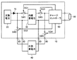
図1は、この発明の実施の形態に従う独立電源システムの構成を示すブロック図である。 FIG. 1 is a block diagram showing a configuration of an independent power supply system according to the embodiment of the present invention.
図1を参照して、独立電源システム10は、太陽電池20と、システム内部に配される小型低容量の蓄電池(以下、内蔵蓄電池とも称する)30と、システム外部に配される大容量の蓄電池(以下、外部蓄電池とも称する)40と、各蓄電池から出力される直流電力を電気負荷60に供給するチャージコントローラ50と、逆流防止ダイオード70とを備える。
Referring to FIG. 1, an independent
太陽電池20は、複数セルの太陽電池素子が直列に結合されたモジュール構造であり、定格電圧および定格電力をそれぞれ25V,55Wとする。本実施の形態では、携帯用テレビなどの民生機器を用途とすることを考慮して、例えば、薄膜基板上に形成される集積型アモルファスシリコン太陽電池が用いられる。
内蔵蓄電池30は、太陽電池20と並列に結合され、太陽電池20の発電する直流電力を蓄積する。内蔵蓄電池30は、例えば容量が5.4Ahであり、エネルギー密度が高く、軽量のリチウムイオン電池が用いられる。内蔵蓄電池30の容量は、従来の独立電源システムに搭載される一般的な鉛蓄電池の容量の約1/5に相当する。したがって、本実施の形態の独立電源システムは、蓄電池が飛躍的に小形軽量化されることから、携帯することが可能となる。
The built-in
外部蓄電池40は、太陽電池20と並列に結合され、太陽電池20の発電する直流電力を蓄積する。外部蓄電池40は、図1に示すように、独立電源システム10の外部に配置され、コネクタ80により、独立電源システム10に自在に着脱することができる。外部蓄電池40は、例えば容量を12Ahとし、コスト面を鑑みて、比較的安価な鉛蓄電池が用いられる。なお、本実施の形態の外部蓄電池40は、従来の独立電源システムに搭載される蓄電池の容量とほぼ同等の容量を有し、内蔵蓄電池30に対して体積、重量ともに著しく大きい。
The
内蔵蓄電池30および外部蓄電池40は、図1に示すスイッチ回路SW1,SW2をオン/オフすることにより、それぞれ個別に、太陽電池20と電気的に結合/分離される。スイッチ回路SW1,SW2は、相補的にオンすることから、2つの蓄電池のいずれか一方が太陽電池20に選択的に結合される。かかるスイッチング動作の制御については、後に詳述する。
Built-in
表1に、本実施の形態で使用する内蔵蓄電池30および外部蓄電池40の性能の一例を示す。
Table 1 shows an example of the performance of the
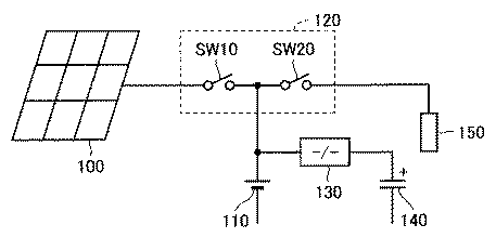
表1を参照して、内蔵蓄電池30は、充電特性として、充電の可否の判定基準となる電圧値を14.4Vとし、端子間電圧がこの電圧値を下回ったことに応じて充電動作を開始する。以下において、該電圧値を充電可能電圧とも称する。
Referring to Table 1, the built-in
さらに、内蔵蓄電池30の充電が進んで満充電状態となると、端子間電圧15.0Vが検出される。以下において、該電圧値を充電停止の判定基準とし、充電停止電圧とも称する。
Furthermore, when the built-in
外部蓄電池40の充電特性についても同様に、表1に示すように、端子間電圧14.2Vを充電可能電圧とし、端子間電圧14.8Vを充電停止電圧とする。
Similarly, as shown in Table 1, the charging characteristics of the
一方、放電特性に関しては、内蔵蓄電池30は、放電の可否の判定基準となる電圧値を12.4Vとし、端子間電圧がこの電圧値を上回るときに放電動作を可能とする。以下において、該電圧値を放電開始電圧とも称する。
On the other hand, with respect to the discharge characteristics, the built-in
さらに、内蔵蓄電池30の放電が進み、過放電状態となると、端子間電圧10.0Vが検出される。以下において、該電圧値を放電停止の判定基準とし、放電停止電圧とも称する。
Further, when the built-in
外部蓄電池40についても同様に、端子間電圧12.4Vを放電開始電圧とし、端子間電圧10.0Vを放電停止電圧とする。
Similarly, with respect to the
ここで、前述のように、ユーザは、コネクタ80によって、外部蓄電池40を独立電源システム10から自在に着脱することができる。したがって、外部蓄電池40が取り外された状態において、独立電源システム10は、小型軽量化されて携帯可能となる。
Here, as described above, the user can freely attach and detach the
詳細には、使用する電気機器の電気負荷60が小さいときには、太陽電池20と内蔵蓄電池30とによって十分な電力を供給できることから、外部蓄電池40を独立電源システム10から取り外した状態とする。これによって、独立電源システム10は、携帯することができる。独立電源システム10は、携帯可能な状態において、例えば、屋外で用いられる携帯用テレビやラジオなどの放送受信機器の電源として、テープレコーダやミニディスクなどの携帯音響機器の電源として、あるいは携帯電話機の充電器として利用されうる。
Specifically, when the
一方、独立電源システム10で、携帯型パソコンのように電気負荷60が大きいものを駆動させたいときには、太陽電池20と内蔵蓄電池30とのみでは十分な電力を賄うことができない。したがって、この場合、ユーザは、コネクタ80を介して容量の大きい外部蓄電池40を独立電源システム10に装着する。これにより、太陽電池20と外部蓄電池40と内蔵蓄電池30とによって、電気負荷60を十分に駆動させることができる。
On the other hand, when it is desired to drive the independent
さらに、電気負荷60の大小に関わらず、気象条件が不良であって十分な照度を安定して得られないときには、太陽電池20の発電能力が衰えることから、外部蓄電池40を装着することで、安定した電力供給を維持することが可能となる。
Furthermore, regardless of the magnitude of the
このような構成とすることにより、様々な負荷を持つ電気機器に対して安定した電力供給を保証するとともに、ユーザの用途に合わせて携帯可能な独立電源システムを構築することができる。 With such a configuration, it is possible to guarantee a stable power supply to an electric device having various loads, and to build an independent power supply system that can be carried in accordance with a user's application.
ここで、独立電源システム10を、ユーザによって指定される任意のタイミングにおいて携帯した状態での使用を可能とするためには、内蔵蓄電池30が、負荷を駆動するのに最低限必要とされる所定の電力量を常に蓄えた状態であることが求められる。
Here, in order to enable use of the independent
そこで、本実施の形態では、以下に示す蓄電池の充放電動作の制御によって内蔵蓄電池の蓄える直流電力をできる限り保持することにより、携帯性に優れた独立電源システムを提案する。 Therefore, in the present embodiment, an independent power supply system excellent in portability is proposed by maintaining DC power stored in the built-in storage battery as much as possible by controlling the charge / discharge operation of the storage battery described below.
図1を参照して、独立電源システム10は、太陽電池20から各蓄電池に対する充電動作と各蓄電池から電気負荷60に対する放電動作とを制御する部位として、スイッチ回路SW1〜SW4と、チャージコントローラ50の内部に配される制御部(図示せず)とをさらに備える。
Referring to FIG. 1, independent
スイッチ回路SW1は、チャージコントローラ50の制御部からの駆動信号SG1に応じてオン/オフし、太陽電池20と内蔵蓄電池30とを電気的に結合/分離する。スイッチ回路SW2は、チャージコントローラ50からの駆動信号SG2に応じてオン/オフし、太陽電池20と外部蓄電池40とを電気的に結合/分離する。スイッチ回路SW3は、チャージコントローラ50からの駆動信号SG3に応じてオン/オフし、内蔵蓄電池30とチャージコントローラ50とを電気的に結合/分離する。スイッチ回路SW4は、チャージコントローラ50からの駆動信号SG4に応じてオン/オフし、外部蓄電池40とチャージコントローラ50とを電気的に結合/分離する。
The switch circuit SW1 is turned on / off according to the drive signal SG1 from the control unit of the
本構成において、スイッチ回路SW1とスイッチ回路SW2とは、充電動作時に相補的にオン/オフし、内蔵蓄電池30および外部蓄電池40のいずれか一方と太陽電池20とを選択的に結合する。また、スイッチ回路SW3とスイッチ回路SW4とは、放電動作時に相補的にオン/オフし、内蔵蓄電池30および外部蓄電池40のいずれか一方とチャージコントローラ50とを選択的に結合する。これらのスイッチ回路SW1〜SW4のオン/オフ制御は、チャージコントローラ50内の制御部の発生する駆動信号SG1〜SG4に応答して行なわれる。以下に、かかる充放電動作の制御について詳細に説明する。
In this configuration, the switch circuit SW1 and the switch circuit SW2 are turned on / off complementarily during the charging operation, and selectively connect either the built-in
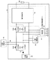
図2は、図1の独立電源システム10の詳細を説明するための回路構成図である。
FIG. 2 is a circuit configuration diagram for explaining details of the independent
図2を参照して、太陽電池20の陽極と内蔵蓄電池30の陽極との間には、図1のスイッチ回路SW1として、NチャネルトランジスタTr1が結合される。同様に、太陽電池20の陽極と外部蓄電池40の陽極との間には、図1のスイッチ回路SW2として、NチャネルトランジスタTr2が結合される。これらのNチャネルトランジスタTr1,Tr2は、駆動信号SG1,SG2の活性化(「H(論理ハイ)」レベル)に応答してそれぞれオンし、対応する蓄電池と太陽電池20とを電気的に結合する。
Referring to FIG. 2, between the anode of the anode and the built-in
さらに、内部蓄電池30の陽極とチャージコントローラ50内の電力供給部51との間には、図1のスイッチ回路SW3として、NチャネルトランジスタTr3が結合される。同様に、外部蓄電池40の陽極と電力供給部51との間には、図1のスイッチ回路SW4として、NチャネルトランジスタTr4が結合される。これらのNチャネルトランジスタTr3,Tr4は、駆動信号SG3,SG4の活性化(「H」レベル)に応じてそれぞれオンし、対応する蓄電池と電力供給部51とを電気的に結合する。
Further, an N-channel transistor Tr3 is coupled between the anode of the
なお、スイッチ回路SW1〜SW4は、本実施の形態で例示するNチャネルトランジスタに特定されず、電気的信号に応答して開閉するその他のスイッチング素子が適用可能である。 Note that the switching circuits SW1 to SW4 are not limited to the N-channel transistors exemplified in this embodiment, and other switching elements that open and close in response to electrical signals are applicable.
チャージコントローラ50は、図2に示すように、放電状態にある蓄電池から出力される直流電力を電気負荷60に供給する電力供給部51と、駆動信号SG1〜SG4を発生して前述の充放電動作を制御する制御部52とを含む。
As shown in FIG. 2, the
電力供給部51は、一例として、図3に示すように、蓄電池から出力される直流電力を交流電力に変換して電気負荷60に供給するインバータ部51Aで構成される。
As an example, the
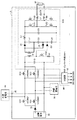
図3は、図2の独立電源システム10の一例を説明するための回路構成図である。なお、図3は、図2のチャージコントローラ50における電力供給部51を、インバータ部51Aに変更したものである。
FIG. 3 is a circuit configuration diagram for explaining an example of the independent
図3を参照して、インバータ部51Aは、蓄電池の出力直流電圧を昇圧させるための昇圧トランスT1と、整流回路と、フィルタ回路と、自励式インバータと、出力フィルタ回路とに大別される。
Referring to FIG. 3,
昇圧トランスT1は、NチャネルトランジスタTr50のオン/オフ制御によって直流から交流に変換された電力を1次側に入力し、ピーク電圧が約135Vになるように昇圧された交流電力が2次側に出力される。 The step-up transformer T1 inputs, to the primary side, power converted from direct current to alternating current by on / off control of the N-channel transistor Tr50, and the AC power boosted so that the peak voltage becomes about 135V is input to the secondary side. Is output.
昇圧トランスT1にて生成された交流電力は、整流回路に入力される。整流回路は、変圧器T1の2次側のコイルに対して互いに逆方向に接続されたダイオードD1,D2と、ダイオードD1のカソードとダイオードD2のアノードとの間に直列接続されたコンデンサC2,C3とを含む。 The AC power generated by the step-up transformer T1 is input to the rectifier circuit. The rectifier circuit includes diodes D1, D2 connected in opposite directions to the secondary coil of the transformer T1, and capacitors C2, C3 connected in series between the cathode of the diode D1 and the anode of the diode D2. Including.
整流回路は、全波形であり、コンデンサC2,C3がそれぞれ交流電圧のピーク値にまで充電されることにより、入力される交流電圧のピーク値の約2倍に相当する約270Vの出力電圧が得られる。 The rectifier circuit has a full waveform, and when the capacitors C2 and C3 are charged to the peak value of the AC voltage, respectively, an output voltage of about 270 V corresponding to about twice the peak value of the input AC voltage is obtained. It is done.
さらに、コンデンサC2,C3と直列に接続されるコンデンサC4は、ダイオードD3を介して蓄電池の端子間電圧に充電される。したがって、コンデンサC2〜C4の端子間に出力される直流電圧は、約284Vとなる。 Furthermore, the capacitor C4 connected in series with the capacitors C2 and C3 is charged to the voltage between the terminals of the storage battery via the diode D3. Therefore, the DC voltage output between the terminals of the capacitors C2 to C4 is about 284V.
フィルタ回路は、インダクタL1とコンデンサC5とを含み、得られた直流電圧から高周波成分を除去して、後段の自励式インバータに伝達する。 The filter circuit includes an inductor L1 and a capacitor C5, removes a high frequency component from the obtained DC voltage, and transmits it to the subsequent self-excited inverter.
自励式インバータは、NチャネルトランジスタTr51,Tr54からなるスイッチ回路の組とNチャネルトランジスタTr52,Tr53からなるスイッチ回路の組とを交互に導通させることによって、入力される直流電力を周波数60Hzの交流電力に変換する。なお、スイッチ回路の開閉は、制御部52からの制御信号によって制御される。得られた交流電力は、出力フィルタ回路を通して電気負荷60に供給される。出力フィルタ回路は、チョークコイルL2と、コンデンサC6とから構成される。なお、直流電力を交流電力に変換する方式として、PWM(パルス幅変調)制御を用いることもできる。
The self-excited inverter alternately turns on a set of switch circuits consisting of N-channel transistors Tr51 and Tr54 and a set of switch circuits consisting of N-channel transistors Tr52 and Tr53 to convert the input DC power to AC power with a frequency of 60 Hz. Convert to The opening / closing of the switch circuit is controlled by a control signal from the
また、図3において、図2の電力供給部51をインバータ部51Aで構成する例について説明したが、他の一例として、電力供給部51を、蓄電池の出力する直流電力を電力変換せずに電気負荷60に供給する構成としてもよい。
3, the example in which the
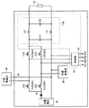
図4は、図2の独立電源システム10の他の例を説明するための回路構成図である。なお、図4は、図2のチャージコントローラ50における電力供給部51を、電力供給部51Bに変更したものである。
FIG. 4 is a circuit configuration diagram for explaining another example of the independent
図4を参照して、電力供給部51Bは、インダクタL3,L4とコンデンサC7,C8とからなるフィルタ回路を含む。 Referring to FIG. 4, power supply unit 51B includes a filter circuit including inductors L3 and L4 and capacitors C7 and C8.
フィルタ回路は、放電状態にある蓄電池から得られた直流電力を、高周波成分を除去して電気負荷60へ出力する。このとき、図示は省略するが、電力供給部51Bにおいて、さらに昇圧回路または降圧回路を設けることによって、直流電力の電圧を所望の電圧レベルに昇圧または降圧して電気負荷60に供給する構成とすることができる。
The filter circuit removes high-frequency components from the DC power obtained from the storage battery in a discharged state and outputs the DC power to the
また、電力供給部51を、電気負荷60に対して、交流電力と直流電力とのいずれ一方を選択的に供給できる構成とすれば、接続される電気負荷60に適した電力を供給することが可能となる。
Moreover, if the
次に、チャージコントローラ50の制御部52が行なう各蓄電池の充放電制御について説明する。なお、以下の制御は、図2〜図4に示す独立電源システム10のいずれの制御部52においても共通して行なわれるものである。
Next, charge / discharge control of each storage battery performed by the
図2を参照して、制御部52は、内蔵蓄電池30および外部蓄電池40の端子間電圧を常時検出し、各蓄電池に対して充放電を実行/停止させるための駆動信号SG1〜SG4を出力する。
Referring to FIG. 2,
詳細には、制御部52は、内蔵蓄電池30の端子間電圧を検出し、内蔵蓄電池30が充電可能な状態にあるか否かを判定する。端子間電圧が表1に示す充電可能電圧14.4V以下であるときには、内蔵蓄電池30が充電可能であると判定し、制御部52は、活性化(「H」レベル)した駆動信号SG1を出力する。その後、充電停止電圧15.0Vに達して満充電状態であることを検出したときには、充電不可能であると判定して、非活性化(「L(論理ロー)」レベル)した駆動信号SG1を出力する。
In detail, the
制御部52は、外部蓄電池40についても同様に、端子間電圧を検出し、外部蓄電池40が充電可能な状態にあるか否かを判定する。詳細には、制御部52は、外部蓄電池40の端子間電圧を検出し、外部蓄電池40が充電可能な状態にあるか否かを判定する。端子間電圧が表1に示す充電可能電圧14.2V以下であるときには、外部蓄電池40が充電可能であると判定し、制御部52は、活性化(「H」レベル)した駆動信号SG2を出力する。その後、端子間電圧が充電停止電圧14.8Vに達して満充電状態であることを検出したときには、充電不可能であると判定して、非活性化(「L」レベル)した駆動信号SG2を出力する。なお、外部蓄電池40が独立電源システム10に装着されていないときには、駆動信号SG2は「L」レベルに固定される。
Similarly, the
ここで、かかる内蔵蓄電池30と外部蓄電池40との充電動作は、同時に行なわれるものではなく、内蔵蓄電池30が優先的に実行される。詳細には、制御部52は、内蔵蓄電池30が充電可能であると判定したときには、駆動信号SG1を活性化するとともに、相補的に駆動信号SG2を非活性化する。これにより、内蔵蓄電池30は、太陽電池20と結合されて充電動作が開始される一方で、外部蓄電池40は、その充電状態に関わらず強制的に分離される。
Here, the charging operation of the
さらに、制御部52は、内蔵蓄電池30が充電完了したことを検出すると、駆動信号SG1を非活性化するとともに、外部蓄電池40の端子間電圧を検出し、充電可能であれば相補的に駆動信号SG2を活性化する。これにより、内蔵蓄電池30は、太陽電池20と分離される一方で、外部蓄電池40は、太陽電池20と結合されて充電動作が開始される。
Further, when the
図5は、図1の独立電源システム10における充電動作を説明するためのフロー図である。
FIG. 5 is a flowchart for explaining the charging operation in the independent
なお、以下に述べる充電動作の前提として、独立電源システム10のユーザは、電気負荷60の大きさ、使用時間および気象条件などに基づいて、外部蓄電池40を装着するか否かを判断する。ユーザが外部蓄電池40の装着が必要であると判断したときには、コネクタ80を介して外部蓄電池40が装着される。一方、ユーザが外部蓄電池40が不要であると判断したときには、独立電源システム10は、外部蓄電池40が装着されず、携帯可能な状態となる。
As a premise of the charging operation described below, the user of the independent
最初に、内蔵蓄電池30が充電可能か否かが判断される(ステップS02)。詳細には、チャージコントローラ50内の制御部52は、内蔵蓄電池30の端子間電圧を検出し、検出値が充電可能電圧14.4Vよりも低いか否かを判定する。
First, it is determined whether or not the
ステップS03において、内蔵蓄電池30の端子間電圧が充電可能電圧よりも低いときには、制御部52は、活性化した駆動信号SG1と非活性化した駆動信号SG2とを出力する。各駆動信号に応じてスイッチ回路SW1がオンし、スイッチ回路SW2がオフすることにより、内蔵蓄電池30は、太陽電池20と選択的に結合され、外部蓄電池40に優先して太陽電池20の発電した直流電力を蓄える(ステップS03)。
In step S03, when the voltage between the terminals of the
かかる内蔵蓄電池30の充電動作が完了すると、外部蓄電池40の充電に移行する。詳細には、ステップS04において外部蓄電池40が装着されているときには、制御部52は、外部蓄電池40の端子間電圧を検出し、検出値が充電可能電圧14.2Vよりも低いか否かを判定する(ステップS05)。
When the charging operation of the
ステップS05において、外部蓄電池40の端子間電圧が充電可能電圧よりも低いときには、制御部52は、活性化した駆動信号SG2と非活性化した駆動信号SG1とを出力する。各駆動信号に応じてスイッチ回路SW2がオンし、スイッチ回路SW1がオフすることにより、外部蓄電池40は太陽電池20と選択的に結合され、発電した直流電力を蓄える(ステップS06)。
In step S05, when the voltage between the terminals of the
外部蓄電池40の充電は、端子間電圧が充電停止電圧14.8Vに達するまで実行される。最後に、ステップS05において、外部蓄電池40の充電が完了したことが検出されると、制御部52は、駆動信号SG1,SG2をともに非活性化する。これにより、スイッチ回路SW1,SW2はいずれもオフし、各蓄電池と太陽電池20とが分離される(ステップS07)。
The
以上のように、独立電源システム10の充電動作においては、内蔵蓄電池30が外部蓄電池40よりも優先して充電され、内蔵蓄電池30の充電が完了した後に外部蓄電池40の充電に切換えられる。これにより、独立電源システム10は、内蔵蓄電池30に直流電力が早急に蓄えられ、携帯可能な状態に移行することができる
再び図2を参照して、制御部52は、前述の充電動作に並行して、内蔵蓄電池30の端子間電圧を検出し、内蔵蓄電池30が放電可能な状態にあるか否かを判定する。制御部52は、端子間電圧が表1に示す放電開始電圧12.4V以上であるときには、内蔵蓄電池30が放電可能であると判定し、活性化(「H」レベル)した駆動信号SG3を出力する。一方、端子間電圧が放電停止電圧10.0Vに達して過放電状態にあるときには、放電不可能であると判定して、非活性化(「L」レベル)した駆動信号SG3を出力する。
As described above, in the charging operation of the independent
制御部52は、外部蓄電池40についても同様に、端子間電圧を検出し、外部蓄電池40が放電可能な状態にあるか否かを判定する。詳細には、端子間電圧が表1に示す放電開始電圧12.4V以上であるときには、制御部52は、外部蓄電池40が放電可能であると判定し、活性化(「H」レベル)した駆動信号SG4を出力する。一方、端子間電圧が放電停止電圧10.0Vに達して過放電状態にあるときには、放電不可能であると判定して、非活性化(「L」レベル)した駆動信号SG4を出力する。なお、外部蓄電池40が装着されていないときには、駆動信号SG4は「L」レベルに固定される。
Similarly, the
かかる内蔵蓄電池30と外部蓄電池40との放電動作は、先述の充電動作とは対照的に外部蓄電池40が優先的に実行される。詳細には、制御部52は、外部蓄電池40が放電可能であると判定したときには、駆動信号SG4を活性化するとともに、相補的に駆動信号SG3を非活性化する。これにより、外部蓄電池40は、チャージコントローラ50の電力供給部51と結合されて放電動作が開始される一方で、内蔵蓄電池30は、強制的に分離される。
The discharge operation of the
さらに、制御部52は、外部蓄電池40が過放電状態となったことを検出すると、駆動信号SG4を非活性化するとともに、内部蓄電池30の端子間電圧を検出し、放電可能であれば相補的に駆動信号SG3を活性化する。これにより、外部蓄電池40は、チャージコントローラ50と分離される一方で、内蔵蓄電池30は、チャージコントローラ50と結合されて放電動作が開始される。
Furthermore, when the
図6は、図1の独立電源システム10における放電動作を説明するためのフロー図である。
FIG. 6 is a flowchart for explaining the discharge operation in the independent
放電動作の前提として、独立電源システム10のユーザは、電気負荷60の大きさ、使用時間および気象条件などに基づいて、外部蓄電池40の要/不要を判断する。ユーザが外部蓄電池40の装着が必要であると判断したときには、コネクタ80を介して外部蓄電池40が装着される。一方、ユーザが外部蓄電池40が不要であると判断したときには、独立電源システム10は、外部蓄電池40が装着されず、携帯可能な状態となる。
As a premise of the discharge operation, the user of the independent
最初に、独立電源システム10に外部蓄電池40が装着されているか否かが確認される(ステップS12)。
First, it is confirmed whether or not the
ステップS12において、外部蓄電池40が装着されていることが確認されると、外部蓄電池40が放電可能か否かが判断される(ステップS13)。詳細には、チャージコントローラ50内の制御部52は、外部蓄電池40の端子間電圧を検出し、検出値が放電開始電圧12.4Vよりも高いか否かを判定する。
If it is confirmed in step S12 that the
ステップS13において、外部蓄電池40の端子間電圧が放電開始電圧よりも高いときには、制御部52は、活性化した駆動信号SG4と非活性化した駆動信号SG3とを出力する。スイッチ回路SW4がオンするとともに、スイッチ回路SW3がオフすることにより、外部蓄電池40は、チャージコントローラ50と選択的に結合され、内蔵蓄電池30に優先して電気負荷60に電力を供給する(ステップS14)。
In step S13, when the voltage between the terminals of the
一方、外部蓄電池40が過放電状態となり、放電停止電圧10.0Vに達したときには、内蔵蓄電池30の放電動作に移行する。制御部52は、内蔵蓄電池30の端子間電圧を検出し、検出値が放電開始電圧12.4Vよりも高いか否かを判定する(ステップS15)。
On the other hand, when the
ステップS15において、内蔵蓄電池30の端子間電圧が放電開始電圧よりも高いときには、制御部52は、活性化した駆動信号SG3と非活性化した駆動信号SG4とを出力する。スイッチ回路SW3がオンするとともに、スイッチ回路SW4がオフされることにより、内蔵蓄電池30は、チャージコントローラ50と選択的に結合され、電気負荷60に電力を供給する(ステップS16)。
In step S15, when the inter-terminal voltage of the built-in
最後に、ステップS16において、内蔵蓄電池30の過放電状態が検出されると、制御部52は、駆動信号SG3,SG4をともに非活性化する。これにより、スイッチ回路SW3,SW4はいずれもオフし、各蓄電池とチャージコントローラ50とが分離される(ステップS17)。
Finally, in step S16, when the overdischarge state of the
以上のように、独立電源システム10の放電動作においては、外部蓄電池40が内蔵蓄電池30よりも優先して放電され、外部蓄電池40の放電完了後に内蔵蓄電池30の放電に切換えられる。これにより、独立電源システム10は、内蔵蓄電池30の蓄える直流電力が可能な限り保持されることから、携帯可能な状態に素早く対応することができる。
As described above, in the discharge operation of the independent
なお、本実施の形態に従う独立電源システムにおいて、太陽電池は、例示したアモルファスシリコン太陽電池に特定されず、結晶シリコン、または化合物半導体型など任意の太陽電池にも適用することができる。さらには、太陽電池に限らず、燃料電池等の発電装置においても実現可能である。 In the independent power supply system according to the present embodiment, the solar cell is not limited to the exemplified amorphous silicon solar cell, and can be applied to any solar cell such as crystalline silicon or a compound semiconductor type. Furthermore, the present invention is not limited to solar cells, and can be realized in power generation devices such as fuel cells.
以上のように、この発明の実施の形態によれば、外部蓄電池を着脱自在とすることにより、様々な負荷を持つ電気機器に対して電力を安定的に供給でき、かつユーザの用途に応じて携帯可能な独立電源システムを実現することができる。 As described above, according to the embodiment of the present invention, by making the external storage battery detachable, it is possible to stably supply power to electric devices having various loads, and according to the user's application. A portable independent power supply system can be realized.
さらに、内蔵蓄電池および外部蓄電池の充放電動作において、内蔵蓄電池の蓄える直流電力をできる限り保持させることにより、携帯型電源システムとして使用できる状態を維持し、ユーザの指定する任意のタイミングに対応することができる。 Furthermore, in the charge / discharge operation of the internal storage battery and the external storage battery, by maintaining the DC power stored in the internal storage battery as much as possible, the state where it can be used as a portable power supply system is maintained, and any timing specified by the user is supported. Can do.
また、発電手段として太陽電池を利用することから、電力を発生するための燃料を携帯する必要がなく、携帯性がさらに向上する。 Further, since a solar cell is used as the power generation means, it is not necessary to carry fuel for generating electric power, and portability is further improved.
今回開示された実施の形態はすべての点で例示であって制限的なものではないと考えられるべきである。本発明の範囲は上記した説明ではなくて特許請求の範囲によって示され、特許請求の範囲と均等の意味および範囲内でのすべての変更が含まれることが意図される。 The embodiment disclosed this time should be considered as illustrative in all points and not restrictive. The scope of the present invention is defined by the terms of the claims, rather than the description above, and is intended to include any modifications within the scope and meaning equivalent to the terms of the claims.
10 独立電源システム、20,100 太陽電池、30 内蔵蓄電池、40 外部蓄電池、50 チャージコントローラ、51,51B 電力供給部、51A インバータ部、52 制御部、60 電気負荷、70 逆流防止ダイオード、80 コネクタ、110 鉛蓄電池、120 充放電制御回路、130 双方向コンバータ、140 電気2重層コンデンサ、150 負荷、SW1〜SW4,SW10,SW20 スイッチ回路、Tr1〜Tr4,Tr50〜Tr54 Nチャネルトランジスタ、T1 変圧器、D1〜D3 ダイオード、C1〜C8 コンデンサ、L1,L3,L4 インダクタ、L2 チョークコイル、R1 抵抗。 10 independent power system, 20,100 solar cell, 30 built-in storage battery, 40 external storage battery, 50 charge controller, 51, 51B power supply unit, 51A inverter unit, 52 control unit, 60 electrical load, 70 backflow prevention diode, 80 connector, 110 lead storage battery, 120 charge / discharge control circuit, 130 bidirectional converter, 140 electric double layer capacitor, 150 load, SW1-SW4, SW10, SW20 switch circuit, Tr1-Tr4, Tr50-Tr54 N-channel transistor, T1 transformer, D1 ~ D3 diode, C1-C8 capacitor, L1, L3, L4 inductor, L2 choke coil, R1 resistor.
Claims (6)
発電した直流電圧を出力する直流電源と、
前記直流電源に第1の開閉手段を介して接続され、前記直流電圧により充電される一方で、第1の直流電力を放電する第1の蓄電池と、
前記独立電源システムに着脱可能に構成された第2の蓄電池が装着された状態において、前記第2の蓄電池と前記独立電源システムとの電気的接続を確保するための接続部と、
前記独立電源システムに装着された状態の前記第2の蓄電池を、前記直流電源に対して前記第1の蓄電池と並列に接続するための第2の開閉手段と、
前記第1の蓄電池に第3の開閉手段を介して接続され、前記第1の直流電力を前記負荷に供給する電力供給部と、
前記独立電源システムに装着された状態の前記第2の蓄電池を、前記電力供給部に対して前記第1の蓄電池と並列に接続するための第4の開閉手段と、
前記第2の蓄電池の装着が検出されたことに応じて、前記第1および第2の蓄電池の充放電動作を制御する制御部とを備え、
前記制御部は、
充電に係わる前記第1および第2の開閉手段のうち、前記第1の開閉手段のみを閉状態として前記直流電圧により前記第1の蓄電池を充電するとともに、前記第1の蓄電池の充電完了後において、前記第2の開閉手段のみを閉状態として前記直流電圧により前記第2の蓄電池を充電する充電制御手段と、
放電に係わる前記第3および第4の開閉手段のうち、前記第4の開閉手段のみを閉状態として前記第2の蓄電池から第2の直流電力を放電するとともに、前記第2の蓄電池の放電完了後において、前記第3の開閉手段のみを閉状態として前記第1の蓄電池から前記第1の直流電力を放電する放電制御手段とを含む、独立電源システム。 An independent power supply system that drives a load with power generated by receiving natural energy,
A DC power supply that outputs the generated DC voltage;
The DC power source is connected via a first switching means, while that will be charged by the DC voltage, a first battery which discharges the first DC power,
In a state in which the second storage battery configured to be detachable from the independent power supply system is mounted, a connection unit for ensuring electrical connection between the second storage battery and the independent power supply system ;
A second opening / closing means for connecting the second storage battery mounted in the independent power supply system in parallel with the first storage battery to the DC power supply ;
A power supply unit connected to the first storage battery via third switching means, and supplying the first DC power to the load ;
A fourth opening / closing means for connecting the second storage battery mounted in the independent power supply system in parallel with the first storage battery to the power supply unit;
A controller that controls charging / discharging operations of the first and second storage batteries in response to detection of attachment of the second storage battery ,
The controller is
Among the first and second opening / closing means related to charging, only the first opening / closing means is closed to charge the first storage battery with the DC voltage, and after the charging of the first storage battery is completed Charging control means for charging the second storage battery with the DC voltage with only the second opening / closing means closed ;
Of the third and fourth opening / closing means related to the discharge, only the fourth opening / closing means is closed to discharge the second DC power from the second storage battery, and the second storage battery is completely discharged. And a discharge control means for discharging the first DC power from the first storage battery with only the third opening / closing means closed .
前記第1および第2の蓄電池の端子間電圧を検出する検出手段と、
検出した前記端子間電圧に基づいて、対応する蓄電池が充電可能か否かを判定する第1の判定手段とをさらに含み、
前記充電制御手段は、前記第1の蓄電池が充電可能であるという判定結果に応じて、前記第1の開閉手段のみを閉状態とする一方で、前記第1の蓄電池が充電不可能であるという判定結果を受けて前記第2の蓄電池が充電可能か否かを判定し、前記第2の蓄電池が充電可能であるという判定結果に応じて、前記第2の開閉手段のみを閉状態とする、請求項2に記載の独立電源システム。 The controller is
Detecting means for detecting a voltage between terminals of the first and second storage batteries;
Based on the detected terminal voltage, wherein the corresponding storage battery further and first determining means for determining whether rechargeable
According to the determination result that the first storage battery is chargeable, the charge control means closes only the first opening / closing means while the first storage battery is not chargeable. In response to the determination result, it is determined whether or not the second storage battery can be charged, and only the second opening / closing means is closed according to the determination result that the second storage battery is chargeable. The independent power supply system according to claim 2.
前記放電制御手段は、前記第2の蓄電池が放電可能であるという判定結果に応じて、前記第4の開閉手段のみを閉状態とする一方で、前記第2の蓄電池が放電不可能であるという判定結果を受けて前記第1の蓄電池が放電可能か否かを判定し、前記第1の蓄電池が放電可能であるという判定結果に応じて、前記第3の開閉手段のみを閉状態とする、請求項3に記載の独立電源システム。 The control unit further includes second determination means for determining whether or not the corresponding storage battery can be discharged based on the detected inter-terminal voltage,
According to the determination result that the second storage battery can be discharged, the discharge control means closes only the fourth opening / closing means, while the second storage battery cannot be discharged. In response to the determination result, it is determined whether or not the first storage battery can be discharged, and only the third opening / closing means is closed according to the determination result that the first storage battery can be discharged. The independent power supply system according to claim 3.
Priority Applications (4)
| Application Number | Priority Date | Filing Date | Title |
|---|---|---|---|
| JP2004262833A JP3887635B2 (en) | 2003-10-30 | 2004-09-09 | Independent power system |
| US10/974,918 US20050093514A1 (en) | 2003-10-30 | 2004-10-28 | Portable independent source system |
| EP04025772A EP1528652B1 (en) | 2003-10-30 | 2004-10-29 | Portable independent electric power source |
| ES04025772T ES2383891T3 (en) | 2003-10-30 | 2004-10-29 | Portable stand-alone power source |
Applications Claiming Priority (2)
| Application Number | Priority Date | Filing Date | Title |
|---|---|---|---|
| JP2003370005 | 2003-10-30 | ||
| JP2004262833A JP3887635B2 (en) | 2003-10-30 | 2004-09-09 | Independent power system |
Publications (2)
| Publication Number | Publication Date |
|---|---|
| JP2005160290A JP2005160290A (en) | 2005-06-16 |
| JP3887635B2 true JP3887635B2 (en) | 2007-02-28 |
Family
ID=34425408
Family Applications (1)
| Application Number | Title | Priority Date | Filing Date |
|---|---|---|---|
| JP2004262833A Expired - Fee Related JP3887635B2 (en) | 2003-10-30 | 2004-09-09 | Independent power system |
Country Status (4)
| Country | Link |
|---|---|
| US (1) | US20050093514A1 (en) |
| EP (1) | EP1528652B1 (en) |
| JP (1) | JP3887635B2 (en) |
| ES (1) | ES2383891T3 (en) |
Families Citing this family (43)
| Publication number | Priority date | Publication date | Assignee | Title |
|---|---|---|---|---|
| CN100421488C (en) * | 2005-05-10 | 2008-09-24 | 英华达(上海)电子有限公司 | Cell phone with solar power supply function |
| JP4111215B2 (en) * | 2005-09-26 | 2008-07-02 | 松下電工株式会社 | Power supply |
| JP4974593B2 (en) * | 2006-06-23 | 2012-07-11 | 三洋電機株式会社 | Power supply for vehicle |
| US7705560B2 (en) * | 2006-08-15 | 2010-04-27 | N. P. Johnson Family Limited Partnership | Voltage controller |
| JP2008228558A (en) * | 2006-11-30 | 2008-09-25 | Beijing Hi-Tech Wealth Investment & Development Co Ltd | Method, arrangement, and system of power supply using photoelectric cell |
| ITBS20060216A1 (en) * | 2006-12-12 | 2008-06-13 | Salvatore Agosta | CONTROLLED SOLAR PANEL SYSTEM |
| TW200830687A (en) * | 2007-01-15 | 2008-07-16 | zhen-yue Fan | Control apparatus of solar power system |
| JP2009033892A (en) * | 2007-07-27 | 2009-02-12 | Panasonic Corp | Independent power supply system |
| JP2010098874A (en) * | 2008-10-17 | 2010-04-30 | Willcom Inc | Mobile communication terminal |
| US8427098B2 (en) * | 2009-04-01 | 2013-04-23 | Eaglepicher Technologies, Llc | Hybrid energy storage system, renewable energy system including the storage system, and method of using same |
| US8004232B2 (en) * | 2009-05-27 | 2011-08-23 | Miasole | Method of battery charging and power control in conjunction with maximum power point tracking |
| US8853995B2 (en) | 2009-06-12 | 2014-10-07 | Qualcomm Incorporated | Devices for conveying wireless power and methods of operation thereof |
| DE102009030319A1 (en) * | 2009-06-24 | 2011-02-03 | Enocean Gmbh | Supply energy arrangement and method for providing a supply energy |
| ITPA20090016A1 (en) * | 2009-07-13 | 2011-01-14 | Ludovico Ingoglia | RECHARGING CONTROL SYSTEM FOR ELECTRIC VEHICLE BATTERIES. |
| JP2011036081A (en) * | 2009-08-04 | 2011-02-17 | Sanyo Electric Co Ltd | Charging system |
| US8547057B2 (en) | 2009-11-17 | 2013-10-01 | Qualcomm Incorporated | Systems and methods for selective wireless power transfer |
| KR101570809B1 (en) * | 2010-10-18 | 2015-11-20 | 한국전자통신연구원 | Method and Apparatus for Tracking Maximum Power Point |
| EP2600488A3 (en) | 2011-01-26 | 2015-03-11 | Mohamed Papa Talla Fall | Energy converting apparatus and method |
| JP5775324B2 (en) * | 2011-02-23 | 2015-09-09 | 大和ハウス工業株式会社 | Battery system |
| TWI460963B (en) * | 2011-09-05 | 2014-11-11 | Delta Electronics Inc | Photovoltaic powered system with adaptive power control and method of operating the same |
| JP2013135533A (en) * | 2011-12-26 | 2013-07-08 | Sanyo Electric Co Ltd | Power storage system and power supply method therefor |
| CN102595274A (en) * | 2012-01-19 | 2012-07-18 | 宁波日兴电子有限公司 | High-fidelity (Hi-fi) plastic shell sound box system with storage battery |
| JP2015084607A (en) * | 2012-02-08 | 2015-04-30 | 新神戸電機株式会社 | Power storage system |
| JP5868254B2 (en) * | 2012-04-25 | 2016-02-24 | 大阪瓦斯株式会社 | Power supply system |
| CN202918218U (en) * | 2012-08-16 | 2013-05-01 | 中兴通讯股份有限公司 | Energy conservation and environmental protection apparatus of communication system equipment |
| IN2015DN01550A (en) * | 2012-09-03 | 2015-07-03 | Robert Bosch Sea Pte Ltd | |
| DE102013005974B8 (en) * | 2013-04-09 | 2015-03-12 | Florian Ilmberger | Battery storage system and method for operating a battery storage system |
| EP3089315A4 (en) * | 2013-12-27 | 2017-10-04 | Fujikura Ltd. | Electricity storage system and electricity storage method |
| US10910681B2 (en) | 2014-02-24 | 2021-02-02 | Ravensafe, LLC | Portable renewable energy power system |
| US9865903B1 (en) | 2014-02-24 | 2018-01-09 | Unlimited Power, LTD. | Portable renewable energy power system |
| JP2015231281A (en) * | 2014-06-04 | 2015-12-21 | 東芝ライテック株式会社 | Illuminating device |
| JP2016032379A (en) * | 2014-07-30 | 2016-03-07 | 株式会社イーエフイー | Power supply system |
| JP5857119B1 (en) * | 2014-12-18 | 2016-02-10 | 株式会社フジクラ | Power storage system and power storage method |
| EP3238325A2 (en) * | 2014-12-24 | 2017-11-01 | Passive Eye Limited | Tracking device and power module |
| CN104796503A (en) * | 2015-04-16 | 2015-07-22 | 杭州华鼎太阳能科技有限公司 | Novel mobile phone with solar charge function |
| JP2017011845A (en) * | 2015-06-19 | 2017-01-12 | カシオ計算機株式会社 | Charger, electric apparatus and charging method |
| JP2017158265A (en) * | 2016-02-29 | 2017-09-07 | パナソニックIpマネジメント株式会社 | Electric power supply system and electric power conversion system |
| US9966771B2 (en) * | 2016-03-18 | 2018-05-08 | Goplug Bags, Inc. | Power bank system |
| JP7052326B2 (en) * | 2017-12-05 | 2022-04-12 | 富士通株式会社 | Power supply and communication equipment |
| CN111971812A (en) | 2018-03-26 | 2020-11-20 | 米沃奇电动工具公司 | High power battery powered portable power supply |
| US11271415B2 (en) | 2018-05-18 | 2022-03-08 | Milwaukee Electric Tool Corporation | Portable power source |
| US11716050B2 (en) | 2018-11-07 | 2023-08-01 | Ravensafe, LLC | Modular power array |
| USD933010S1 (en) | 2019-05-29 | 2021-10-12 | Milwaukee Electric Tool Corporation | Portable power source |
Family Cites Families (7)
| Publication number | Priority date | Publication date | Assignee | Title |
|---|---|---|---|---|
| JPH0946926A (en) * | 1995-08-01 | 1997-02-14 | Japan Storage Battery Co Ltd | Distributed power unit |
| JPH09121461A (en) * | 1995-10-23 | 1997-05-06 | Hitachi Ltd | Self-charging battery and electric apparatus employing it |
| US6034506A (en) * | 1998-01-16 | 2000-03-07 | Space Systems/Loral, Inc. | Lithium ion satellite battery charge control circuit |
| US6034560A (en) * | 1998-04-29 | 2000-03-07 | Trw Inc. | Digital pulse generator |
| JP2000341875A (en) * | 1999-05-24 | 2000-12-08 | Kyocera Corp | Solar generator |
| KR100595718B1 (en) * | 2000-07-28 | 2006-07-03 | 엘지전자 주식회사 | Secondary smart battery connection apparatus and method of portable computer system |
| JP2002058175A (en) * | 2000-08-07 | 2002-02-22 | Japan Storage Battery Co Ltd | Independent power supply system |
-
2004
- 2004-09-09 JP JP2004262833A patent/JP3887635B2/en not_active Expired - Fee Related
- 2004-10-28 US US10/974,918 patent/US20050093514A1/en not_active Abandoned
- 2004-10-29 EP EP04025772A patent/EP1528652B1/en not_active Expired - Fee Related
- 2004-10-29 ES ES04025772T patent/ES2383891T3/en active Active
Also Published As
| Publication number | Publication date |
|---|---|
| ES2383891T3 (en) | 2012-06-27 |
| EP1528652B1 (en) | 2012-04-25 |
| US20050093514A1 (en) | 2005-05-05 |
| EP1528652A2 (en) | 2005-05-04 |
| JP2005160290A (en) | 2005-06-16 |
| EP1528652A3 (en) | 2005-10-12 |
Similar Documents
| Publication | Publication Date | Title |
|---|---|---|
| JP3887635B2 (en) | Independent power system | |
| JP3826929B2 (en) | Battery pack | |
| US7049711B2 (en) | Uninterruptible power system | |
| KR102290478B1 (en) | Battery management circuits, charging standby equipment and power management methods | |
| Chen et al. | Design of a reflex-based bidirectional converter with the energy recovery function | |
| US20050242772A1 (en) | Electronic device | |
| US20050057215A1 (en) | Systems and methods for charging a battery | |
| CN101425749A (en) | Bidirectional power converters | |
| CN101237152A (en) | Electronic device and system for DC voltage conversion | |
| JP2005137054A (en) | Power source circuit | |
| CN101120618A (en) | A power supply | |
| JPH09121461A (en) | Self-charging battery and electric apparatus employing it | |
| JP4564940B2 (en) | Electronic device and battery pack and load device used in the electronic device | |
| CN1402901A (en) | Battery pack | |
| US8384356B2 (en) | Self contained power source | |
| US20070229022A1 (en) | Power-Supply Unit | |
| JP2004336974A (en) | Power supply | |
| JP2004320982A (en) | Electronic equipment | |
| WO2002099947A1 (en) | Power unit and method for power supply of power unit | |
| JP2003339127A (en) | Uninterruptible power supply | |
| CN217693117U (en) | Starting circuit, voltage conversion circuit and electronic equipment | |
| JP4186218B2 (en) | Secondary battery pack | |
| JP4495138B2 (en) | Power supply system, power supply system control method, and power supply system control program | |
| JP2012050184A (en) | Power unit | |
| JPH08308113A (en) | Method and device for charging secondary battery |
Legal Events
| Date | Code | Title | Description |
|---|---|---|---|
| A977 | Report on retrieval |
Free format text: JAPANESE INTERMEDIATE CODE: A971007 Effective date: 20060607 |
|
| A131 | Notification of reasons for refusal |
Free format text: JAPANESE INTERMEDIATE CODE: A131 Effective date: 20060613 |
|
| A521 | Request for written amendment filed |
Free format text: JAPANESE INTERMEDIATE CODE: A523 Effective date: 20060809 |
|
| TRDD | Decision of grant or rejection written | ||
| A01 | Written decision to grant a patent or to grant a registration (utility model) |
Free format text: JAPANESE INTERMEDIATE CODE: A01 Effective date: 20061121 |
|
| A61 | First payment of annual fees (during grant procedure) |
Free format text: JAPANESE INTERMEDIATE CODE: A61 Effective date: 20061127 |
|
| R150 | Certificate of patent or registration of utility model |
Free format text: JAPANESE INTERMEDIATE CODE: R150 |
|
| LAPS | Cancellation because of no payment of annual fees |