JP3886826B2 - Building unit and construction method - Google Patents
Building unit and construction method Download PDFInfo
- Publication number
- JP3886826B2 JP3886826B2 JP2002062518A JP2002062518A JP3886826B2 JP 3886826 B2 JP3886826 B2 JP 3886826B2 JP 2002062518 A JP2002062518 A JP 2002062518A JP 2002062518 A JP2002062518 A JP 2002062518A JP 3886826 B2 JP3886826 B2 JP 3886826B2
- Authority
- JP
- Japan
- Prior art keywords
- column
- columns
- jig
- building unit
- temporary
- Prior art date
- Legal status (The legal status is an assumption and is not a legal conclusion. Google has not performed a legal analysis and makes no representation as to the accuracy of the status listed.)
- Expired - Fee Related
Links
Images


Description
【0001】
【発明の属する技術分野】
本発明は、建物ユニットおよび建物ユニットを用いた建物の施工方法に関する。
【0002】
【背景の技術】
近年、工場で生産された複数の建物ユニットを組み合わせて建てられるユニット建物が、施工期間が短いなどの利点を備えるため広く採用されるようになってきた。
このユニット建物を構成する建物ユニットは、鉄骨製の柱、梁を用いて直方体状に組み立てたフレームに、床面材や壁面材を貼り付けたもので、より具体的には、四隅に鉄骨製の柱が配置され、これらの柱の上端部どうしおよび下端部どうしに鉄骨製の梁が掛け渡されたものである。
【0003】
そして、従来より工業化生産される建物ユニットとしては、たとえば、特公平8−16350号公報に示すように、複数の柱のうち少なくとも一本の柱を上梁部および下梁部から取り外し可能な仮柱で構成した建物ユニットが知られている。
この技術の建物ユニットによれば、複数の建物ユニットをその仮柱を互いに隣接するように配置し、次いでこれら仮柱を取り外すことにより、仮柱が存在していた個所に空間を形成することができ、間取りの自由度を増すことができる等の利点がある。
【0004】
【発明が解決しようとする課題】
ところで、前記建物ユニットに備えられている仮柱は、上梁部と下梁部との間に架設されて他の柱と同様に上梁部を支持しているので、仮柱から上梁部および下梁部に抗力が作用している。
したがって、仮柱を取り外すに際して仮柱と上梁部および下梁部との間に摩擦力が生じるため、この摩擦力に抗して仮柱を動かさなければならず、よって仮柱が取り外しにくいといった課題があった。
そして、このような課題を解決するため、本発明者等は、鋭意研究した結果、たとえば特願2000−368724号(発明の名称「建物ユニットおよび建物の施工方法」)等を発明した。
ところが、このような技術においては、次のような解決すべき課題が残されている。
すなわち、仮柱が他の柱と違ってほぼ同等の断面積であるため、仮柱が4本重なるような場所では、仮柱の着脱(ボルトの取り外しなど)の作業スペースが十分でなく作業性に問題があることである。
【0005】
本発明は、このような従来の課題を解決し、仮柱を取り外す際の作業性を向上させることのできる建物ユニットおよび建物の施工方法を提供することにある。
【0006】
【課題を解決するための手段】
請求項1記載の発明の建物ユニットは、複数の柱と、当該柱の上端部どうしを連結する複数の上梁と、前記柱の下端部どうしを連結する複数の下梁とを備え、複数の前記柱のうち少なくとも一本が前記上梁および下梁から取り外し可能な仮柱となっている建物ユニットにおいて、前記仮柱は、上下に分割可能な治具柱と、上部治具柱の上端に備えられ上梁に固定される上部固定板と、下部治具柱の下端に備えられ下梁に固定される下部固定板とからなり、上下の治具柱は、建物ユニットの他の柱よりも外寸を小さくして形成されるとともに、前記各固定板の内側隅部に位置して設けられていることを特徴としている。
【0007】
請求項1記載の発明にかかる建物ユニットによれば、仮柱が上下に分割可能な治具柱とされ、上部治具柱の上端には建物ユニットの上梁に固定される上部固定板が、また下部時具柱の下端には建物ユニットの下梁に固定される下部固定板がそれぞれ形成されているため、各固定板の固定を建物ユニットの梁から解除し、上部と下部の治具柱の連結を解除すれば、仮柱が上下に分割されて容易に取り外すことができる。
しかも、この取り外しに当り、治具柱は、建物ユニットの他の柱よりも外寸を小さくして形成されるとともに、各固定板の内側隅部に位置して設けられたので、治具柱が4本集中するような場所においても、作業スペースを確保することができ、仮柱を取り外す際の作業性を向上させる。
【0009】
さらに、請求項2記載の発明にかかる建物ユニットでは、仮柱を構成する上下の治具柱のうちの上部治具柱を、下部治具柱よりも短く形成しているため、上下の治具柱の着脱にあたり、ほぼ作業者が立った位置のままで着脱作業ができ、作業性を良くすることができる。
【0010】
請求項3記載の発明にかかる建物ユニットは、四隅に柱が配置され、これらの柱の上端部どうしおよび下端部どうしに梁が掛け渡された箱状のラーメン構造とされた建物ユニットであって、前記柱の少なくとも一つを着脱自在とされた仮柱とし、前記仮柱は、建物ユニットの他の柱よりも外寸を小さくして形成された治具柱と、治具柱の上端に備えられ上梁に固定される上部固定板と、治具柱の下端に備えられ下梁に固定される下部固定板とからなり、前記治具柱は前記各固定板の内側隅部に位置して設けられているので、治具柱が4本集中するような場所においては、仮柱が建物の内側に入り込む形態となり、仮柱の取り外しに当り、作業スペースを確保することができ、仮柱を取り外す際の作業性を向上させることができる。
【0012】
そして、請求項4に記載の建物の施工方法は、四隅に柱が配置され、これらの柱の上端部どうしおよび下端部どうしに梁が掛け渡された箱状のラーメン構造とされた建物ユニットを、水平方向ならびに垂直方法に複数並べて施工する建物の施工方法であって、これら複数の建物ユニットのうち少なくともひとつの建物ユニットを、柱の少なくとも一つが着脱自在とされた仮柱付建物ユニットとし、しかもこの仮柱付建物ユニットの仮柱を、建物ユニットの他の柱の外寸よりも小さくした治具柱と、治具柱の上端を上梁に固定する上部固定板と、治具柱の下端を下梁に固定する下部固定板とから形成し、前記治具柱を前記各固定板の内側隅部に位置して設けることを特徴としている。
そして請求項4に記載の施工方法によれば、仮柱付建物ユニットの仮柱を、建物ユニットの他の柱の外寸よりも小さくした治具柱と、治具柱の上端を上梁に固定する上部固定板と、治具柱の下端を下梁に固定する下部固定板とから形成し、前記治具柱を前記各固定板の内側隅部に位置して設けることとしたので、仮柱付建物ユニットを据え付けるだけで、仮柱周囲の作業空間を広くとることができ、仮柱付建物ユニットの仮柱の取り外し作業を、容易にすることができる。
【0013】
【発明の実施の形態】
以下、本発明にかかる建物ユニットおよび建物ユニットの施工方法の実施例を、図面に基づいて説明する。
【0014】
建物ユニット1は、建物の天井部を構成する上梁部2と、建物の床部を構成する下梁部5と、上梁部2と下梁部5との間に架設されている3本の柱8および仮柱10とを備えている。
【0015】
上梁部2は、上梁(長辺上梁)3、3と上梁(短辺上梁)4、4とで組み立てられた矩形状の枠に、図示しない複数の天井根太を一方の長辺上梁3から他方の短辺上梁3にわたって互いに平行にかつ等間隔に架設したものである。
そして、3本の柱8の上端部と仮柱10の上端部とを上梁3、3、4、4が連結している。
【0016】
下梁部5は、下梁(長辺下梁)6、6と下梁(短辺下梁)7、7とで組み立てられた矩形状の枠に、図示しない複数の床根太を一方の長辺下梁6から他方の長辺下梁6にわたって互いに平行にかつ等間隔に架設したものである。
そして、3本の柱8の下端部と仮柱10の下端部とを下梁6、6、7、7が連結している。
【0017】
仮柱10は、上梁部2および下梁部5に取り外し可能に接合されている部材であって、実施例では、仮柱10は、自身の長さ方向に2つの治具柱11、12に分けられており、上部治具柱11と下部治具柱12とがクリアランスをもって連結部材20により連結されている(図3参照)。なお、クリアランス10の長さ(高さ)としては約10mmに設定されている。
治具柱11、12は中空部を有する断面矩形状の長尺部材であり、上部治具柱11は上梁部2に接合され、下部治具柱12は下梁部5に接合されている。
【0018】
また、上部治具柱11の上端には、上梁に固定される上部固定板24が設けられ、下部治具柱12の下端には下梁に固定される下部固定板25が設けられ、各固定板24、25にはそれぞれ梁に固定するためのボルトの挿通孔24a、25aが形成されている。
なお、上下の治具柱11、12は、建物ユニット1の他の柱8よりも外寸を小さくして形成されており、また、建物ユニット1の内側になるような位置に配置されている。
実施例では、図5および図6に示すように、治具柱11、12の隣接する2つの側面に位置するように固定板24、25が取り付けられ、これにより、治具柱が建物ユニット1の各固定板の内側隅部に位置して設けられる形態とされ、仮柱を建物ユニット1に配置した際に、治具柱11,12が建物ユニット1の内側に配置される構造となっている。
【0019】
なお、仮柱10を構成する上下の治具柱11、12のうち上部治具柱11は、下部治具柱12よりも短く形成され、上下の治具柱11、12を連結した際に、これらの接続部がほぼ作業者の立ち位置となるように配慮されている。
図5および図6中符号26、27はそれぞれ各固定板24、25を補強する補強板であり、固定板と治具柱との間に亘って取り付けられている。
【0020】
上部治具柱11と下部治具柱12との接合構造は、図3および図4に示すような構造となっている。すなわち、図3に示すように上部治具柱11の下部側面11a、11bには、治具柱11の内部に貫通するねじ付の柱側係合孔14がそれぞれ2つ形成され、下部治具柱12の上部側面12a、12bには、内部に貫通するねじ付の柱側係合孔15がそれぞれ2つ形成されている。
【0021】
また、上部治具柱11と下部治具柱12とは、L字型に形成された連結部材20により連結されるようになっており、具体的には、連結部材20の2つの当接面20a、20bを上下の治具柱11、12の間を連結部材20が覆うように沿わせて当てがい、連結部材20に形成された上下の係合孔21、22と、治具柱11、12の係合孔14、15とを合わせて外側からボルト23を差し込んで固定するものである。
【0022】
次に、以上のように構成された建物ユニット1を用いて建物を施工する方法を説明する。なお、本実施例では、建物ユニット1を4つ用いて建物ユニット4つ分の広さを有する大空間を形成する方法について説明する(図7参照)。
【0023】
この建物ユニット1を用いて建物を、図7に示すように施工するには、4つの建物ユニット1を、仮柱10が互いに隣接するようにして設置し、隣合う上梁3、4どうしおよび下梁6、7どうしを接合すれば良い。
建物ユニット1には、工場等において、他の柱の外寸よりも小さくした仮柱10を固定しておき、建物ユニット1の内側に寄せるように配置しておくことは勿論である。
そして、このようにすることによって、仮柱10が集中する部分は、外寸が小さい仮柱10が、建物ユニットの内側によるような配置形態となって、仮柱周囲の作業空間が広くなり、以下に説明するように、仮柱付建物ユニットの仮柱の取り外し作業を、容易にすることができるものである。
【0024】
すなわち、図7に示すように設置した建物ユニット1から仮柱10を取り外すには、まず、連結部材20を固定しているボルト23を取り外し、仮柱10を構成する上下の治具柱11、12の連結を解除する。
次いで、上下の治具柱11、12を梁に固定している固定板24、25のボルトを取れば、治具柱11、12は固定が外れて、建物ユニット1から取り外される事となる。
この際、外寸の小さい仮柱10の間には、ボルトを取り外すための作業空間が十分に確保され、固定板24、25の間分の作業空間が建物ユニット1間に確保されるため、治具柱が4本集中するような場所においても、作業スペースを確保することができ、仮柱を取り外す際の作業性を向上させることができる。
【0025】
また、実施例では、仮柱10を構成する上下の治具柱11、12のうちの上部治具柱11を、下部治具柱12よりも短く形成し、上下の治具柱11、12の連結部分を作業者の立ち位置となるよう設定しているために、下の治具柱の着脱にあたり、ほぼ作業者が立った位置のままで着脱作業ができ、作業性を良くすることができるといった利点もある。
【0026】
なお、実施例では、治具柱11と治具柱12との間に適当なクリアランスが形成されているため、上下の治具柱11、12の連結を解除した際に、このクリアランスによって、治具柱11、12を容易に取り外すことができる利点もある。
【0027】
なお、この発明は、上記の実施例に限定されるものではなく、当業者が容易に思いつくような設計変更等も含むものである。例えば、この実施例では上下に2つに仮柱10を分割するようにしたが3分割、4分割することであっても良いことは勿論である。
【0028】
【発明の効果】
以上説明したように、本発明によれば、仮柱が上下に分割可能な治具柱とされ、上部治具柱の上端には建物ユニットの上梁に固定される上部固定板が、また下部時具柱の下端には建物ユニットの下梁に固定される下部固定板がそれぞれ形成されているため、各固定板の固定を建物ユニットの梁から解除し、上部と下部の治具柱の連結を解除すれば、仮柱が上下に分割されて容易に取り外すことができる。
しかも、この取り外しに当り、治具柱は、建物ユニットの他の柱よりも外寸を小さくして形成されているので、治具柱が4本集中するような場所においても、作業スペースを確保することができ、仮柱を取り外す際の作業性を向上させる。また、本発明にかかる建物の施工方法によれば、仮柱付建物ユニットの仮柱を、建物ユニットの他の柱の外寸よりも小さくして各固定板の内側隅部に位置して設けることとしたので、仮柱付建物ユニットを据え付けるだけで、仮柱周囲の作業空間を広くとることができ、仮柱付建物ユニットの仮柱の取り外し作業を、容易にすることができる。
【図面の簡単な説明】
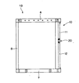
【図1】本発明を適用した一実施例の建物ユニットの構成を示す斜視図である。
【図2】本発明を適用した一実施例の建物ユニットの構成を示す側面図である。
【図3】本発明を適用した一実施例の建物ユニットの仮柱の連結部を示す斜視図である。
【図4】本発明を適用した一実施例の建物ユニットの仮柱の連結部を示す斜視図である。
【図5】本発明を適用した一実施例の上部治具柱示す平面図である。
【図6】本発明を適用した一実施例の下部治具柱示す平面図である。
【図7】本発明を適用した一実施例の施工方法を説明する建物ユニットの平面図である。
【符号の説明】
1 建物ユニット
2 上梁部
3、4 上梁
5 下梁部
6,7 下梁
10 仮柱
11 上部治具柱
12 下部治具柱
20 連結部材
24 上部固定板
25 下部固定板
26、27補強板[0001]
BACKGROUND OF THE INVENTION
The present invention relates to a building unit and a building construction method using the building unit.
[0002]
[Background technology]
In recent years, unit buildings constructed by combining a plurality of building units produced in factories have come to be widely adopted because they have advantages such as a short construction period.
The building unit that composes this unit building is a frame assembled with a rectangular parallelepiped shape using steel columns and beams, and floor materials and wall materials are pasted. More specifically, it is made of steel frames at the four corners. These columns are arranged, and steel beams are spanned between upper end portions and lower end portions of these columns.
[0003]
As a building unit that is industrially produced from the past, for example, as shown in Japanese Patent Publication No. 8-16350, at least one of the plurality of columns can be removed from the upper beam portion and the lower beam portion. Building units composed of pillars are known.
According to the building unit of this technology, a plurality of building units are arranged so that the temporary pillars are adjacent to each other, and then, by removing these temporary pillars, a space can be formed at the place where the temporary pillars existed. There is an advantage that the degree of freedom of the layout can be increased.
[0004]
[Problems to be solved by the invention]
By the way, the temporary column provided in the building unit is constructed between the upper beam portion and the lower beam portion and supports the upper beam portion like the other columns. And drag acts on the lower beam part.
Accordingly, when removing the temporary column, a frictional force is generated between the temporary column and the upper beam portion and the lower beam portion. Therefore, the temporary column must be moved against this frictional force, and thus the temporary column is difficult to remove. There was a problem.
And in order to solve such a subject, as a result of earnest research, the present inventors invented Japanese Patent Application No. 2000-368724 (invention name “building unit and construction method”).
However, in such a technique, the following problems to be solved remain.
In other words, unlike the other columns, the temporary columns have almost the same cross-sectional area, so in places where four temporary columns overlap, the work space for mounting and removing the temporary columns (such as bolt removal) is not sufficient and workability is improved. There is a problem.
[0005]
An object of the present invention is to provide a building unit and a building construction method capable of solving such a conventional problem and improving workability when removing a temporary column.
[0006]
[Means for Solving the Problems]
The building unit of the invention according to claim 1 includes a plurality of columns, a plurality of upper beams that connect the upper ends of the columns, and a plurality of lower beams that connect the lower ends of the columns. In the building unit in which at least one of the columns is a temporary column that can be removed from the upper beam and the lower beam, the temporary column is arranged on the upper end of the upper and lower jig columns. The upper fixing plate is fixed to the upper beam and the lower fixing plate is fixed to the lower beam and is fixed to the lower beam. Rutotomoni formed by reducing the outer dimension, and wherein are provided located inside corners of the fixing plate.
[0007]
According to the building unit according to the invention of claim 1, the temporary column is a jig column that can be divided vertically, and the upper fixing plate fixed to the upper beam of the building unit at the upper end of the upper jig column, In addition, the lower fixture plate has a lower fixing plate that is fixed to the lower beam of the building unit. Therefore, the fixing plate is released from the beam of the building unit, and the upper and lower jig columns are fixed. If the connection is released, the temporary pillar is divided into upper and lower parts and can be easily removed.
Moreover, per this removal, Chiguhashira is formed by reducing the outer dimensions than the other columns of the building unit Rutotomoni so provided located inside corners of the fixing plate, Chiguhashira Even in a place where the four are concentrated, a work space can be secured and workability when removing the temporary column is improved.
[0009]
Furthermore, in the building unit according to the second aspect of the invention, the upper jig column of the upper and lower jig columns constituting the temporary column is formed shorter than the lower jig column. In attaching and detaching the pillar, the attaching and detaching work can be performed with the worker almost standing, and the workability can be improved.
[0010]
The building unit according to the invention described in
[0012]
The building construction method according to
And according to the construction method of
[0013]
DETAILED DESCRIPTION OF THE INVENTION
Embodiments of a building unit and a building unit construction method according to the present invention will be described below with reference to the drawings.
[0014]
The building unit 1 includes three
[0015]
The
The
[0016]
The
The
[0017]
The
The
[0018]
Further, an
Note that the upper and
In the embodiment, as shown in FIGS. 5 and 6, the fixing
[0019]
Of the upper and
[0020]
The joining structure of the
[0021]
Further, the
[0022]
Next, a method for constructing a building using the building unit 1 configured as described above will be described. In addition, a present Example demonstrates the method of forming the large space which has the area for four building units using four building units 1 (refer FIG. 7).
[0023]
In order to construct a building using the building unit 1 as shown in FIG. 7, the four building units 1 are installed so that the
Of course, in the factory or the like, the
And by doing in this way, the part where the
[0024]
That is, in order to remove the
Next, if the bolts of the fixing
At this time, a work space for removing the bolt is sufficiently secured between the
[0025]
In the embodiment, the
[0026]
In the embodiment, an appropriate clearance is formed between the
[0027]
The present invention is not limited to the above-described embodiments, but includes design changes and the like that a person skilled in the art can easily conceive. For example, in this embodiment, the
[0028]
【The invention's effect】
As described above, according to the present invention, the temporary column is a jig column that can be divided into upper and lower parts, and an upper fixing plate that is fixed to the upper beam of the building unit is provided at the upper end of the upper jig column. Since the lower fixing plate fixed to the lower beam of the building unit is formed at the lower end of the tool post, the fixing plate is released from the beam of the building unit and the upper and lower jig columns are connected. Is released, the temporary pillar is divided into upper and lower parts and can be easily removed.
In addition, the jig pillar is formed with a smaller outside dimension than the other pillars of the building unit for this removal, ensuring work space even in locations where four jig pillars are concentrated. This improves the workability when removing the temporary pillar. Moreover, according to the construction method of the building concerning this invention, the temporary column of a building unit with a temporary column is made smaller than the outer dimension of the other column of a building unit, and is located in the inner corner of each fixed plate. Therefore, the work space around the temporary column can be widened only by installing the building unit with temporary columns, and the removal work of the temporary column of the building units with temporary columns can be facilitated.
[Brief description of the drawings]
FIG. 1 is a perspective view showing a configuration of a building unit according to an embodiment to which the present invention is applied.
FIG. 2 is a side view showing a configuration of a building unit according to an embodiment to which the present invention is applied.
FIG. 3 is a perspective view showing a connecting portion of temporary columns of a building unit according to an embodiment to which the present invention is applied.
FIG. 4 is a perspective view showing a connecting portion of temporary columns of a building unit according to an embodiment to which the present invention is applied.
FIG. 5 is a plan view showing an upper jig column of one embodiment to which the present invention is applied.
FIG. 6 is a plan view showing a lower jig column of one embodiment to which the present invention is applied.
FIG. 7 is a plan view of a building unit for explaining a construction method according to an embodiment to which the present invention is applied.
[Explanation of symbols]
DESCRIPTION OF SYMBOLS 1
Claims (4)
複数の前記柱のうち少なくとも一本が前記上梁および下梁から取り外し可能な仮柱となっている建物ユニットにおいて、
前記仮柱は、上下に分割可能な治具柱と、上部治具柱の上端に備えられ上梁に固定される上部固定板と、下部治具柱の下端に備えられ下梁に固定される下部固定板とからなり、上下の治具柱は、建物ユニットの他の柱よりも外寸を小さくして形成されるとともに、前記各固定板の内側隅部に位置して設けられていることを特徴とする建物ユニット。A plurality of columns, a plurality of upper beams that connect the upper ends of the columns, and a plurality of lower beams that connect the lower ends of the columns,
In the building unit in which at least one of the plurality of columns is a temporary column removable from the upper beam and the lower beam,
The temporary column is divided into upper and lower jig columns, an upper fixing plate provided at the upper end of the upper jig column and fixed to the upper beam, and provided at the lower end of the lower jig column and fixed to the lower beam. composed of a lower fixed plate, the upper and lower jigs pillar Rutotomoni formed by reducing the outer dimensions than the other columns of the building unit, said can is provided located inside corners of the fixed plate A building unit characterized by
前記柱の少なくとも一つが着脱自在とされた仮柱とされ、
前記仮柱は、建物ユニットの他の柱よりも外寸を小さくして形成された治具柱と、治具柱の上端に備えられ上梁に固定される上部固定板と、治具柱の下端に備えられ下梁に固定される下部固定板とからなり、前記治具柱は前記各固定板の内側隅部に位置して設けられていることを特徴とする建物ユニット。It is a building unit having a box-shaped ramen structure in which pillars are arranged at four corners, and beams are spanned between upper ends and lower ends of these pillars,
At least one of the pillars is a detachable temporary pillar,
The temporary column includes a jig column formed with a smaller outside dimension than the other columns of the building unit, an upper fixing plate provided at the upper end of the jig column and fixed to the upper beam, A building unit comprising a lower fixing plate provided at a lower end and fixed to a lower beam, wherein the jig column is provided at an inner corner of each fixing plate .
これら複数の建物ユニットのうち少なくともひとつの建物ユニットを、柱の少なくとも一つが着脱自在とされた仮柱付建物ユニットとし、
しかもこの仮柱付建物ユニットの仮柱を、建物ユニットの他の柱よりも外寸を小さくした治具柱と、治具柱の上端を上梁に固定する上部固定板と、治具柱の下端を下梁に固定する下部固定板とから形成し、前記治具柱を前記各固定板の内側隅部に位置して設けることで、隣接する建物ユニットの柱との間に作業空間を形成することを特徴とする建物の施工方法。Construction of a building in which pillars are arranged at the four corners and a plurality of building units with a box-like ramen structure in which beams are spanned between the upper and lower ends of these pillars are arranged side by side in the horizontal and vertical directions. A method,
At least one of the plurality of building units is a building unit with a temporary column in which at least one of the columns is detachable,
Moreover, the temporary column of the building unit with temporary columns is a jig column whose outer dimensions are smaller than the other columns of the building unit, an upper fixing plate that fixes the upper end of the jig column to the upper beam, and a jig column. A lower fixed plate that fixes the lower end of the fixed plate to the lower beam, and the jig column is provided at the inner corner of each fixed plate, thereby providing a work space between the columns of adjacent building units. A building construction method characterized by forming.
Priority Applications (1)
| Application Number | Priority Date | Filing Date | Title |
|---|---|---|---|
| JP2002062518A JP3886826B2 (en) | 2002-03-07 | 2002-03-07 | Building unit and construction method |
Applications Claiming Priority (1)
| Application Number | Priority Date | Filing Date | Title |
|---|---|---|---|
| JP2002062518A JP3886826B2 (en) | 2002-03-07 | 2002-03-07 | Building unit and construction method |
Publications (2)
| Publication Number | Publication Date |
|---|---|
| JP2003261984A JP2003261984A (en) | 2003-09-19 |
| JP3886826B2 true JP3886826B2 (en) | 2007-02-28 |
Family
ID=29196253
Family Applications (1)
| Application Number | Title | Priority Date | Filing Date |
|---|---|---|---|
| JP2002062518A Expired - Fee Related JP3886826B2 (en) | 2002-03-07 | 2002-03-07 | Building unit and construction method |
Country Status (1)
| Country | Link |
|---|---|
| JP (1) | JP3886826B2 (en) |
-
2002
- 2002-03-07 JP JP2002062518A patent/JP3886826B2/en not_active Expired - Fee Related
Also Published As
| Publication number | Publication date |
|---|---|
| JP2003261984A (en) | 2003-09-19 |
Similar Documents
| Publication | Publication Date | Title |
|---|---|---|
| JP2006152557A (en) | Steel house structure and steel house construction method | |
| JP5478864B2 (en) | Connection structure, unit type building, construction method | |
| JP4503982B2 (en) | Reinforced beams and unit buildings with the reinforced beams | |
| JP5400283B2 (en) | Building unit connection structure and unit building | |
| JP2002097722A (en) | Unit type building and corner reinforcing material therefor | |
| JP3886826B2 (en) | Building unit and construction method | |
| JP3787348B2 (en) | Steel house panel structure and panel construction method | |
| JP4328455B2 (en) | Unit building | |
| JPH1061025A (en) | Unit building and construction method thereof | |
| JP2001164658A (en) | Beam joining structure and unit building | |
| JP7032051B2 (en) | Floor structure construction method and floor structure reuse method | |
| JP4717245B2 (en) | Unit buildings and corner reinforcements for unit buildings | |
| JPH06185122A (en) | Building unit, and unit building using the same | |
| JP4044676B2 (en) | Unit building | |
| JP3887233B2 (en) | Unit building | |
| JP2018115491A (en) | Building structure | |
| JP4700178B2 (en) | Unit building | |
| JP4449891B2 (en) | Unit building | |
| JP5010406B2 (en) | Building unit and unit building | |
| JP4381631B2 (en) | Unit building shed structure | |
| JP3359417B2 (en) | Building unit, unit building and construction method of unit building | |
| JP2000265568A (en) | Unit building | |
| JPH1061020A (en) | Unit building and construction method thereof | |
| JPH1061022A (en) | Unit building and construction method thereof | |
| JP2004092313A (en) | Metal joint for building units |
Legal Events
| Date | Code | Title | Description |
|---|---|---|---|
| A621 | Written request for application examination |
Free format text: JAPANESE INTERMEDIATE CODE: A621 Effective date: 20050303 |
|
| A131 | Notification of reasons for refusal |
Free format text: JAPANESE INTERMEDIATE CODE: A131 Effective date: 20060808 |
|
| A521 | Request for written amendment filed |
Free format text: JAPANESE INTERMEDIATE CODE: A523 Effective date: 20061010 |
|
| TRDD | Decision of grant or rejection written | ||
| A01 | Written decision to grant a patent or to grant a registration (utility model) |
Free format text: JAPANESE INTERMEDIATE CODE: A01 Effective date: 20061121 |
|
| A61 | First payment of annual fees (during grant procedure) |
Free format text: JAPANESE INTERMEDIATE CODE: A61 Effective date: 20061122 |
|
| R150 | Certificate of patent or registration of utility model |
Free format text: JAPANESE INTERMEDIATE CODE: R150 Ref document number: 3886826 Country of ref document: JP Free format text: JAPANESE INTERMEDIATE CODE: R150 |
|
| FPAY | Renewal fee payment (event date is renewal date of database) |
Free format text: PAYMENT UNTIL: 20091201 Year of fee payment: 3 |
|
| S111 | Request for change of ownership or part of ownership |
Free format text: JAPANESE INTERMEDIATE CODE: R313111 |
|
| FPAY | Renewal fee payment (event date is renewal date of database) |
Free format text: PAYMENT UNTIL: 20091201 Year of fee payment: 3 |
|
| R350 | Written notification of registration of transfer |
Free format text: JAPANESE INTERMEDIATE CODE: R350 |
|
| FPAY | Renewal fee payment (event date is renewal date of database) |
Free format text: PAYMENT UNTIL: 20091201 Year of fee payment: 3 |
|
| FPAY | Renewal fee payment (event date is renewal date of database) |
Free format text: PAYMENT UNTIL: 20101201 Year of fee payment: 4 |
|
| FPAY | Renewal fee payment (event date is renewal date of database) |
Free format text: PAYMENT UNTIL: 20101201 Year of fee payment: 4 |
|
| FPAY | Renewal fee payment (event date is renewal date of database) |
Free format text: PAYMENT UNTIL: 20111201 Year of fee payment: 5 |
|
| FPAY | Renewal fee payment (event date is renewal date of database) |
Free format text: PAYMENT UNTIL: 20121201 Year of fee payment: 6 |
|
| FPAY | Renewal fee payment (event date is renewal date of database) |
Free format text: PAYMENT UNTIL: 20131201 Year of fee payment: 7 |
|
| LAPS | Cancellation because of no payment of annual fees |