JP3881518B2 - Fluid oscillator - Google Patents
Fluid oscillator Download PDFInfo
- Publication number
- JP3881518B2 JP3881518B2 JP2000576965A JP2000576965A JP3881518B2 JP 3881518 B2 JP3881518 B2 JP 3881518B2 JP 2000576965 A JP2000576965 A JP 2000576965A JP 2000576965 A JP2000576965 A JP 2000576965A JP 3881518 B2 JP3881518 B2 JP 3881518B2
- Authority
- JP
- Japan
- Prior art keywords
- fluid
- oscillation chamber
- pair
- outlet
- power
- Prior art date
- Legal status (The legal status is an assumption and is not a legal conclusion. Google has not performed a legal analysis and makes no representation as to the accuracy of the status listed.)
- Expired - Lifetime
Links
Images


Classifications
-
- B—PERFORMING OPERATIONS; TRANSPORTING
- B05—SPRAYING OR ATOMISING IN GENERAL; APPLYING FLUENT MATERIALS TO SURFACES, IN GENERAL
- B05B—SPRAYING APPARATUS; ATOMISING APPARATUS; NOZZLES
- B05B1/00—Nozzles, spray heads or other outlets, with or without auxiliary devices such as valves, heating means
- B05B1/02—Nozzles, spray heads or other outlets, with or without auxiliary devices such as valves, heating means designed to produce a jet, spray, or other discharge of particular shape or nature, e.g. in single drops, or having an outlet of particular shape
- B05B1/08—Nozzles, spray heads or other outlets, with or without auxiliary devices such as valves, heating means designed to produce a jet, spray, or other discharge of particular shape or nature, e.g. in single drops, or having an outlet of particular shape of pulsating nature, e.g. delivering liquid in successive separate quantities ; Fluidic oscillators
-
- F—MECHANICAL ENGINEERING; LIGHTING; HEATING; WEAPONS; BLASTING
- F15—FLUID-PRESSURE ACTUATORS; HYDRAULICS OR PNEUMATICS IN GENERAL
- F15C—FLUID-CIRCUIT ELEMENTS PREDOMINANTLY USED FOR COMPUTING OR CONTROL PURPOSES
- F15C1/00—Circuit elements having no moving parts
- F15C1/22—Oscillators
-
- Y—GENERAL TAGGING OF NEW TECHNOLOGICAL DEVELOPMENTS; GENERAL TAGGING OF CROSS-SECTIONAL TECHNOLOGIES SPANNING OVER SEVERAL SECTIONS OF THE IPC; TECHNICAL SUBJECTS COVERED BY FORMER USPC CROSS-REFERENCE ART COLLECTIONS [XRACs] AND DIGESTS
- Y10—TECHNICAL SUBJECTS COVERED BY FORMER USPC
- Y10T—TECHNICAL SUBJECTS COVERED BY FORMER US CLASSIFICATION
- Y10T137/00—Fluid handling
- Y10T137/0318—Processes
- Y10T137/0396—Involving pressure control
-
- Y—GENERAL TAGGING OF NEW TECHNOLOGICAL DEVELOPMENTS; GENERAL TAGGING OF CROSS-SECTIONAL TECHNOLOGIES SPANNING OVER SEVERAL SECTIONS OF THE IPC; TECHNICAL SUBJECTS COVERED BY FORMER USPC CROSS-REFERENCE ART COLLECTIONS [XRACs] AND DIGESTS
- Y10—TECHNICAL SUBJECTS COVERED BY FORMER USPC
- Y10T—TECHNICAL SUBJECTS COVERED BY FORMER US CLASSIFICATION
- Y10T137/00—Fluid handling
- Y10T137/206—Flow affected by fluid contact, energy field or coanda effect [e.g., pure fluid device or system]
- Y10T137/2087—Means to cause rotational flow of fluid [e.g., vortex generator]
- Y10T137/2093—Plural vortex generators
-
- Y—GENERAL TAGGING OF NEW TECHNOLOGICAL DEVELOPMENTS; GENERAL TAGGING OF CROSS-SECTIONAL TECHNOLOGIES SPANNING OVER SEVERAL SECTIONS OF THE IPC; TECHNICAL SUBJECTS COVERED BY FORMER USPC CROSS-REFERENCE ART COLLECTIONS [XRACs] AND DIGESTS
- Y10—TECHNICAL SUBJECTS COVERED BY FORMER USPC
- Y10T—TECHNICAL SUBJECTS COVERED BY FORMER US CLASSIFICATION
- Y10T137/00—Fluid handling
- Y10T137/206—Flow affected by fluid contact, energy field or coanda effect [e.g., pure fluid device or system]
- Y10T137/2087—Means to cause rotational flow of fluid [e.g., vortex generator]
- Y10T137/2098—Vortex generator as control for system
-
- Y—GENERAL TAGGING OF NEW TECHNOLOGICAL DEVELOPMENTS; GENERAL TAGGING OF CROSS-SECTIONAL TECHNOLOGIES SPANNING OVER SEVERAL SECTIONS OF THE IPC; TECHNICAL SUBJECTS COVERED BY FORMER USPC CROSS-REFERENCE ART COLLECTIONS [XRACs] AND DIGESTS
- Y10—TECHNICAL SUBJECTS COVERED BY FORMER USPC
- Y10T—TECHNICAL SUBJECTS COVERED BY FORMER US CLASSIFICATION
- Y10T137/00—Fluid handling
- Y10T137/206—Flow affected by fluid contact, energy field or coanda effect [e.g., pure fluid device or system]
- Y10T137/2087—Means to cause rotational flow of fluid [e.g., vortex generator]
- Y10T137/2104—Vortex generator in interaction chamber of device
-
- Y—GENERAL TAGGING OF NEW TECHNOLOGICAL DEVELOPMENTS; GENERAL TAGGING OF CROSS-SECTIONAL TECHNOLOGIES SPANNING OVER SEVERAL SECTIONS OF THE IPC; TECHNICAL SUBJECTS COVERED BY FORMER USPC CROSS-REFERENCE ART COLLECTIONS [XRACs] AND DIGESTS
- Y10—TECHNICAL SUBJECTS COVERED BY FORMER USPC
- Y10T—TECHNICAL SUBJECTS COVERED BY FORMER US CLASSIFICATION
- Y10T137/00—Fluid handling
- Y10T137/206—Flow affected by fluid contact, energy field or coanda effect [e.g., pure fluid device or system]
- Y10T137/2087—Means to cause rotational flow of fluid [e.g., vortex generator]
- Y10T137/2109—By tangential input to axial output [e.g., vortex amplifier]
- Y10T137/2115—With means to vary input or output of device
-
- Y—GENERAL TAGGING OF NEW TECHNOLOGICAL DEVELOPMENTS; GENERAL TAGGING OF CROSS-SECTIONAL TECHNOLOGIES SPANNING OVER SEVERAL SECTIONS OF THE IPC; TECHNICAL SUBJECTS COVERED BY FORMER USPC CROSS-REFERENCE ART COLLECTIONS [XRACs] AND DIGESTS
- Y10—TECHNICAL SUBJECTS COVERED BY FORMER USPC
- Y10T—TECHNICAL SUBJECTS COVERED BY FORMER US CLASSIFICATION
- Y10T137/00—Fluid handling
- Y10T137/206—Flow affected by fluid contact, energy field or coanda effect [e.g., pure fluid device or system]
- Y10T137/218—Means to regulate or vary operation of device
- Y10T137/2185—To vary frequency of pulses or oscillations
-
- Y—GENERAL TAGGING OF NEW TECHNOLOGICAL DEVELOPMENTS; GENERAL TAGGING OF CROSS-SECTIONAL TECHNOLOGIES SPANNING OVER SEVERAL SECTIONS OF THE IPC; TECHNICAL SUBJECTS COVERED BY FORMER USPC CROSS-REFERENCE ART COLLECTIONS [XRACs] AND DIGESTS
- Y10—TECHNICAL SUBJECTS COVERED BY FORMER USPC
- Y10T—TECHNICAL SUBJECTS COVERED BY FORMER US CLASSIFICATION
- Y10T137/00—Fluid handling
- Y10T137/206—Flow affected by fluid contact, energy field or coanda effect [e.g., pure fluid device or system]
- Y10T137/2224—Structure of body of device
-
- Y—GENERAL TAGGING OF NEW TECHNOLOGICAL DEVELOPMENTS; GENERAL TAGGING OF CROSS-SECTIONAL TECHNOLOGIES SPANNING OVER SEVERAL SECTIONS OF THE IPC; TECHNICAL SUBJECTS COVERED BY FORMER USPC CROSS-REFERENCE ART COLLECTIONS [XRACs] AND DIGESTS
- Y10—TECHNICAL SUBJECTS COVERED BY FORMER USPC
- Y10T—TECHNICAL SUBJECTS COVERED BY FORMER US CLASSIFICATION
- Y10T137/00—Fluid handling
- Y10T137/206—Flow affected by fluid contact, energy field or coanda effect [e.g., pure fluid device or system]
- Y10T137/2229—Device including passages having V over T configuration
- Y10T137/2234—And feedback passage[s] or path[s]
Abstract
Description
【0001】
【発明の属する技術分野】
本発明は、流体発振器に関する。
【0002】
【従来の技術】
流体発振器は公知であり、側壁付着効果を有し、または有しないフィードバック通路を使用するものは公知である(側壁付着効果を使用する流体発振器については米国特許第4,463,904号参照。また、側壁付着効果に依存しないまたは使用しない流体発振器については米国特許第4,508,267号参照)。フィードバック通路を使用しない、または備えていない、大気にスプレイを放出する流体発振器がある(発振出力を発生するためにアイランドを使用するStoufferに付与された米国特許第4,151,955参照、反転室型発振器である、Bauerに付与された米国特許第4,184,636号参照)。Stoufferに付与された米国特許第5,213,270号及び米国特許第5,213,269号において、フィードバックまたは制御通路のない他の型式の発振器が開示されており、この発振器において、発振室は、その幅より大きい長さを有し、一対の補完的な形状の対向する側壁を有し、この側壁は、出口で発振するために流れの両側で交互に振動するキャビテーションのない渦を形成する。
【0003】
【課題を解決するための手段】
本発明は、フィードバックまたは制御通路のないタイプの流体発振器に関し、この発振器は、少なくとも1つの出口を有する成形された発振室と、発振室内で互いに所定の角度の向きを有する一対の液体噴流を形成する少なくとも一対のパワーノズルとを有し、一対の噴流は相互に作用し発振室内に複数の渦を発生する。複数の渦は、液体噴流の対の方向を周期的に変化させ、出口で液体の掃引(振動)噴流を生じるように組み合わされる。好ましい実施形態において、発振室は、ドーム形またはマッシュルーム形の内面を有し、パワーノズルに接続されるマニフォルド及び大気への出口は、ドーム形またはマッシュルーム形の内面と反対側の壁にある。
【0004】
動作的には、本装置は、キャビティ内の2つの液体噴流の内部不安定性に基づいている。2つの噴流は、相互作用(発振)室において適当な大きさ及び向きを有し、結果として生じる流れパターンは、本来的に不安定な渦を生成し、2つの噴流の方向を周期的に変化させる。これは、室の出口で掃引噴流を提供する。出口即ち開口は、或る領域をカバーする発振シートか、または平坦な扇形タイプのスプレーのいずれかを生じる構成とすることができる。パワーノズルは、発振室の中心軸線に対して対称的に配向する必要はない。さらに、出口及び出口スロートは、偏揺れ角が変化する掃引噴流を放出するようにすることができる。
【0005】
【発明が解決しようとする課題】
したがって、本発明の目的は、改良された流体発振器、さらに詳細には、流体または液体の掃引(振動)噴流を放出する流体発振器を提供することに関する。
【0006】
【発明の実施の形態】
以下、本発明の一実施形態を図面を参照して詳細に説明する。
本発明の流体発振器は、キャビティの2つの液体または流体の噴流の内部不安定性に基づいている。2つの液体噴流または流れは、相互作用領域(発振室とも呼ばれる)の中で適当なサイズと方向を有し、結果として生じる流れパターンは、本来的に不安定な2つの噴流の方向を周期的に変化させる渦装置である。これは、発振室の出口即ち出力部で掃引噴流を生成する。出口即ち出力部EXの形状、寸法は、領域をカバーする発振シートか、または扇形の平坦なスプレイのいずれかを生成するように構成されている。
【0007】
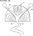
基本的な形状は、図1に示されており、複数のパワーノズルPN1及びPN2を有する相互作用室(発振室)ICを有する。相互作用室の流れは、本来的に不安定な4つの渦をつくる(図2参照)。これは、図2に示すように出口即ち出口開口で掃引噴流SJを生じる。
【0008】
図3においては、相互作用室ICは、図示したように直線的とされ、図4においては、相互作用室IC″は長円形に変形されている。
図5及び図6においては、単一の供給マニフォルドSFが、内部通路とともに使用される(すなわち、複数の内部通路が流れを2つの噴流に分割する)。
【0009】
図7においては、2つのパワーノズル7PN1、7PN2は、それぞれ噴流J1及びJ2を噴出し、これは、ドーム形発振室に向かって傾斜して配置され、偏向器D1、D2が、要求された条件で発振流をつくるように出口EX7に流れを向けるように付加されている。
【0010】
図8は、図7に示す実施例の変形例であり、内部通路とともに使用する単一の供給マニフォルドSFMを備えている。
図7及び図8に示す実施例は、図1−図6及び図10A−図10Eに示す流体発振器より著しく低い振動数を有する。その結果、振動の波長は、著しく長く、複数のパワーノズルを有する比較可能な発振器より約5倍長い。この構成においては、複数の入力パワーノズルPN1″及びPN2″は、出口EX7の反対側で発振室に衝突して出力噴流の振動を生じる。
【0011】
すべての出口形状は、全体または領域をカバーするか、扇形スプレーを得るために変形することができる。この装置は、広範囲な大きさの構造において作動する。また、噴流の場所と向きまたは噴流の寸法のずれかにおいてわずかに非対称とすることによってスプレイは、種々の偏揺れ角度を有するように構成することができる。
【0012】
図9に示す発振器の実施形態は、単一の供給源9CSから流体が供給される複数のパワーノズル9PN1、9PN2を有する。マッシュルーム形の発振室9OCは、複数の出口ポート9OP1、9OP2を有する。
【0013】
この装置は、9OP−1、9OP−2の各々において、互いに位相のずれた脈動性の流れを生じる。寸法、角度Θ1,Θ2及び長さ「1」を変化させることによって、2つの出口において種々の出力流を得ることができる。例示として、2つの出口ポートとの間に異なる質量流量比で脈動流を得るために装置を作動することができる。
【0014】
図面に示すように、回路は、種々の長さ及び幅を有することができる。いくつかの場合において、パワーノズルの長さは、流体回路の他の部分と比較して非常に小さくすることができる。回路の最大幅は、パワーノズルの幅Wを単位として測定され、例えば約15Wの幅である。パワーノズルのマニフォルドの形状は、相互作用室または発振室の一方の壁を形成するものである。いくいつかの回路において、長さは、既存のハウジングに適合するように合わせることができる。図11A及び図11Bにおいては、回路は、パワーノズルのマニフォルドに続く「供給入口ノズル」11FNと称されるものを有する。
【0015】
いくつかの実施形態において、パワーノズルの幅は、異なる幅及び形状とすることができる(図10B)。一対のパワーノズルは、互いにくい違いを有し(図10C参照)、このくい違いは、扇形角度の偏揺れ角度を所望の方向に依存して左または右に偏向させる。いくつかの実施形態において、出口スロートは、スプレーの左側または右側の偏揺れ角度を移動させるために対称中心軸線からわずかに偏っている。いくつかの実施形態において、スロートは、所望のように左または右に所定の偏揺れ角度を生じるために長手軸線方向で少し喰違っている(図10E)。したがって、上述した技術の組み合わせを使用して大部分の用途に適合する偏揺回路を設計することができる。
【0016】
通常、流体回路または輪郭は、射出成形プラスチック製のチップからなり、このプラスチック製チップは、Merkeらへ付与された米国特許第5,845,845号またはBauerに付与された米国特許第4,185,777号に開示されるような流体入力突起部FCCBを有する成形ハウジングに押し込まれる。図12は、面12Fを有し、図示した輪郭または回路の一つが成形された流体回路チップFCCを示しており、このチップには、加圧流体源へ接続されるホース又は他の接続部材を受ける入力突起部FCCBを有するハウジングFCCHに挿入される。これは種々のフィルタ及びチェック弁等(図示せず)を含むこともできる。装置の通常の用途は、流動性材料、液体及びガスのスプレー及び放出を含む。1つの特に有利な用途は、ウインドシールド、自動車のリヤウインドウ、自動車のヘッドランプのようなガラス表面へのウオッシャ液のスプレーである。
【0017】
本発明の好ましい実施形態を図示し説明したが、当業者には本発明の他の実施形態、用途が容易に明らかになるであろう。
【図面の簡単な説明】
【図1】 本発明の基本的な構成を示す図である。
【図2】 図2A、2B及び図2Cは、図1に示す流体発振器の出口での掃引噴流を示す図である。
【図3】 発振室のコーナが直線になっている本発明の他の実施形態を示す図である。
【図4】 発振室が長円形になっている本発明の他の実施形態を示す図である。
【図5】 図5Aは、単一の供給源からの流れを二つの噴流に分割される実施形態を示す図であり、図5Bは、図5Aの斜視図である。
【図6】 単一の供給源からの流れを二つの噴流に分割する実施形態を示す図である。
【図7】 ドーム形の壁の方向へ傾斜して向いている噴流の場所と、振動流を生じるために必要な条件で出口に向かうように流れを向けるために追加された偏向器とを示す図である。
【図8】 図7に示す実施例の変形例を示す図である。
【図9】 本発明による複数の出口を有する複数のパワーノズルを示す図である。
【図10】 図10Aは、本発明の他の実施形態を示す図である。
図10Bは、一方のパワーノズルがスプレイの大気への出力の偏揺れ角度を調整するために他方のパワーノズルより広い幅を備えた複数パワーノズルの発振器を示す図である。
図10Cは、各パワーノズルの軸線が異なる位置で発振器の中心軸線と交差する発振器を示す図である。
図10Dは、出口スロートが右に偏っている同様の発振器を示す図である。
図10Eは、スロートの両側の対向部分が長手方向中心軸線方向に喰違ったスロートを示す図である。
【図11】 図11Aは、単一のパワーノズル供給口を備えた複数のパワーノズル用のマニフォルドを示す図である。図11Bは、図11Aの斜視図である。
【図12】 成形流体回路または輪郭チップ、ハウジング及び流体源の通常の組立工程を示す図である。[0001]
BACKGROUND OF THE INVENTION
The present invention relates to a fluid oscillator.
[0002]
[Prior art]
Fluid oscillators are known, and those using a feedback path with or without sidewall adhesion effects are known (see US Pat. No. 4,463,904 for fluid oscillators using sidewall adhesion effects. Also, sidewall adhesion effects. (See U.S. Pat. No. 4,508,267 for fluid oscillators that do not depend on or are not used). There is a fluid oscillator that emits spray to the atmosphere with or without a feedback path (see US Pat. No. 4,151,955 to Stouffer using islands to generate oscillating output, inverted chamber oscillator U.S. Pat. No. 4,184,636 to Bauer). In U.S. Pat.Nos. 5,213,270 and 5,213,269 to Stouffer, other types of oscillators without feedback or control paths are disclosed, in which the oscillation chamber has a length greater than its width. And having a pair of complementary shaped opposing side walls that form cavitation-free vortices that oscillate alternately on both sides of the flow to oscillate at the outlet.
[0003]
[Means for Solving the Problems]
The present invention relates to a fluid oscillator of the type without a feedback or control passage, the oscillator forming a shaped oscillation chamber having at least one outlet and a pair of liquid jets having a predetermined angular orientation relative to each other in the oscillation chamber The pair of jets interact with each other to generate a plurality of vortices in the oscillation chamber. The vortices are combined to periodically change the direction of the pair of liquid jets to produce a swept (vibrating) jet of liquid at the outlet. In a preferred embodiment, the oscillation chamber has a dome-shaped or mushroom-shaped inner surface, and the manifold connected to the power nozzle and the outlet to the atmosphere are on the wall opposite the dome-shaped or mushroom-shaped inner surface.
[0004]
In operation, the device is based on the internal instability of the two liquid jets in the cavity. The two jets have the right size and orientation in the interaction (oscillation) chamber, and the resulting flow pattern creates an inherently unstable vortex and periodically changes the direction of the two jets Let This provides a swept jet at the chamber exit. The outlet or opening can be configured to produce either an oscillating sheet covering an area or a flat fan-type spray. The power nozzle need not be oriented symmetrically with respect to the central axis of the oscillation chamber. In addition, the outlet and outlet throat can emit a swept jet with varying yaw angle.
[0005]
[Problems to be solved by the invention]
Accordingly, it is an object of the present invention to provide an improved fluid oscillator, and more particularly, a fluid oscillator that emits a swept (vibrating) jet of fluid or liquid.
[0006]
DETAILED DESCRIPTION OF THE INVENTION
Hereinafter, an embodiment of the present invention will be described in detail with reference to the drawings.
The fluid oscillator of the present invention is based on the internal instability of two liquid or fluid jets of cavities. The two liquid jets or flows have the appropriate size and direction within the interaction region (also called the oscillation chamber), and the resulting flow pattern is periodic in the direction of the two inherently unstable jets. It is a vortex device that changes into This produces a swept jet at the exit or output of the oscillation chamber. The shape or size of the outlet or output part EX is configured to generate either an oscillating sheet covering the area or a fan-shaped flat spray.
[0007]
The basic shape is shown in FIG. 1 and includes an interaction chamber (oscillation chamber) IC having a plurality of power nozzles PN1 and PN2. The flow in the interaction chamber creates four vortices that are inherently unstable (see FIG. 2). This produces a swept jet SJ at the exit or exit opening as shown in FIG.
[0008]
In FIG. 3, the interaction chamber IC is linear as shown, and in FIG. 4, the interaction chamber IC ″ is deformed into an oval shape.
5 and 6, a single supply manifold SF is used with an internal passage (ie, multiple internal passages divide the flow into two jets).
[0009]
In FIG. 7, the two power nozzles 7PN1 and 7PN2 eject jets J1 and J2, respectively, which are arranged inclined toward the dome-shaped oscillation chamber, and the deflectors D1 and D2 have the required conditions. Is added to direct the flow to the outlet EX7 so as to create an oscillating flow.
[0010]
FIG. 8 is a variation of the embodiment shown in FIG. 7 and includes a single supply manifold SFM for use with an internal passage.
The embodiment shown in FIGS. 7 and 8 has a significantly lower frequency than the fluid oscillator shown in FIGS. 1-6 and 10A-10E. As a result, the wavelength of vibration is significantly longer, about 5 times longer than comparable oscillators with multiple power nozzles. In this configuration, the plurality of input power nozzles PN1 ″ and PN2 ″ collide with the oscillation chamber on the opposite side of the outlet EX7 and generate vibration of the output jet.
[0011]
All outlet shapes can be deformed to cover the whole or area or to obtain a fan spray. This device operates in a wide range of sizes. In addition, the spray can be configured to have various yaw angles by being slightly asymmetric in the location and orientation of the jet or the dimensional deviation of the jet.
[0012]
The embodiment of the oscillator shown in FIG. 9 has a plurality of power nozzles 9PN1, 9PN2 that are supplied with fluid from a single source 9CS. The mushroom-shaped oscillation chamber 9OC has a plurality of outlet ports 9OP1 and 9OP2.
[0013]
This device produces pulsatile flows out of phase with each other in 9OP-1 and 9OP-2. By varying the dimensions, angles Θ1, Θ2, and length “1”, different output streams can be obtained at the two outlets. By way of example, the device can be operated to obtain a pulsating flow with different mass flow ratios between the two outlet ports.
[0014]
As shown in the drawings, the circuit can have various lengths and widths. In some cases, the length of the power nozzle can be very small compared to other parts of the fluid circuit. The maximum width of the circuit is measured in units of the width W of the power nozzle, and is, for example, about 15 W. The shape of the manifold of the power nozzle forms one wall of the interaction chamber or the oscillation chamber. In some circuits, the length can be tailored to fit an existing housing. In FIGS. 11A and 11B, the circuit has what is referred to as a “supply inlet nozzle” 11FN following the manifold of the power nozzle.
[0015]
In some embodiments, the width of the power nozzle can be different widths and shapes (FIG. 10B). The pair of power nozzles has a difficult difference from each other (see FIG. 10C), which deflects the sector angle yaw angle to the left or right depending on the desired direction. In some embodiments, the outlet throat is slightly offset from the central axis of symmetry to move the yaw angle on the left or right side of the spray. In some embodiments, the throat is slightly misaligned in the longitudinal direction to produce a predetermined yaw angle to the left or right as desired (FIG. 10E). Thus, a combination of the techniques described above can be used to design a yaw circuit that fits most applications.
[0016]
Typically, the fluid circuit or contour consists of an injection molded plastic chip, such as disclosed in US Pat. No. 5,845,845 to Merke et al. Or US Pat. No. 4,185,777 to Bauer. Is pushed into a molding housing having a fluid input projection FCCB. FIG. 12 shows a fluid circuit chip FCC having a face 12F and molded with one of the contours or circuits shown, which has a hose or other connection member connected to a source of pressurized fluid. It is inserted into a housing FCCH having an input projection FCCB for receiving. This can also include various filters, check valves, etc. (not shown). Typical applications for the device include spraying and releasing fluid materials, liquids and gases. One particularly advantageous application is the spraying of washer fluid onto glass surfaces such as windshields, automotive rear windows, automotive headlamps.
[0017]
While the preferred embodiment of the invention has been illustrated and described, other embodiments and applications of the invention will be readily apparent to those skilled in the art.
[Brief description of the drawings]
FIG. 1 is a diagram showing a basic configuration of the present invention.
2A, 2B and 2C are diagrams showing a swept jet at the outlet of the fluid oscillator shown in FIG.
FIG. 3 is a diagram showing another embodiment of the present invention in which the corner of the oscillation chamber is a straight line.
FIG. 4 is a diagram showing another embodiment of the present invention in which the oscillation chamber is oval.
FIG. 5A shows an embodiment in which the flow from a single source is divided into two jets, and FIG. 5B is a perspective view of FIG. 5A.
FIG. 6 illustrates an embodiment in which the flow from a single source is divided into two jets.
FIG. 7 shows the location of a jet that is inclined towards the dome-shaped wall and a deflector added to direct the flow towards the outlet at the conditions necessary to produce an oscillating flow. FIG.
FIG. 8 is a diagram showing a modification of the embodiment shown in FIG.
FIG. 9 illustrates a plurality of power nozzles having a plurality of outlets according to the present invention.
FIG. 10A is a diagram showing another embodiment of the present invention.
FIG. 10B is a diagram showing a multiple power nozzle oscillator with one power nozzle having a wider width than the other power nozzle to adjust the yaw angle of the spray output to the atmosphere.
FIG. 10C is a diagram illustrating an oscillator in which the axis of each power nozzle intersects the central axis of the oscillator at a different position.
FIG. 10D shows a similar oscillator with the outlet throat biased to the right.
FIG. 10E is a diagram showing a throat in which opposing portions on both sides of the throat are different in the longitudinal central axis direction.
FIG. 11A is a diagram showing a manifold for a plurality of power nozzles having a single power nozzle supply port. FIG. 11B is a perspective view of FIG. 11A.
FIG. 12 shows the normal assembly process of a molded fluid circuit or contour chip, housing and fluid source.
Claims (23)
一対の無振動の流体噴流を前記発振室に噴出するために加圧流体源に接続される一対のパワーノズルと、
流体の振動噴流を当該振動噴流を使用する場所に放出するために前記発振室に形成された少なくとも1つの出口と、を有する流体発振器。An oscillation chamber;
The power nozzle of a pair that will be connected to a pressurized fluid source to eject the pair of vibration-free fluid jet to the oscillator chamber,
A fluid oscillator having at least one outlet formed in the oscillation chamber for discharging a vibrating jet of fluid to a place where the vibrating jet is used.
b)一対の無振動のパワー液体噴流を前記中心軸線に対して選択された角度で前記発振室に噴出させ、前記発振室に発振渦を発生させることと、
c)前記発振室から1つまたは複数の振動噴流を放出することと、を有する液体噴流を発振する方法。a) forming an oscillation chamber having a central axis and an outlet;
and that b) is ejected free vibration power liquid jets in a pair in the oscillation chamber at a selected angle relative to the central axis, to generate an oscillating vortex to the oscillation chamber,
c) emitting one or more oscillating jets from the oscillation chamber, and oscillating a liquid jet.
Applications Claiming Priority (5)
| Application Number | Priority Date | Filing Date | Title |
|---|---|---|---|
| US10451198P | 1998-10-16 | 1998-10-16 | |
| US60/104,511 | 1998-10-16 | ||
| US09/417,899 | 1999-10-14 | ||
| US09/417,899 US6253782B1 (en) | 1998-10-16 | 1999-10-14 | Feedback-free fluidic oscillator and method |
| PCT/US1999/021463 WO2000023197A1 (en) | 1998-10-16 | 1999-10-15 | Feedback-free fluidic oscillator and method |
Publications (3)
| Publication Number | Publication Date |
|---|---|
| JP2002527235A JP2002527235A (en) | 2002-08-27 |
| JP2002527235A5 JP2002527235A5 (en) | 2006-07-20 |
| JP3881518B2 true JP3881518B2 (en) | 2007-02-14 |
Family
ID=26801638
Family Applications (1)
| Application Number | Title | Priority Date | Filing Date |
|---|---|---|---|
| JP2000576965A Expired - Lifetime JP3881518B2 (en) | 1998-10-16 | 1999-10-15 | Fluid oscillator |
Country Status (10)
| Country | Link |
|---|---|
| US (1) | US6253782B1 (en) |
| EP (1) | EP1121201B1 (en) |
| JP (1) | JP3881518B2 (en) |
| KR (1) | KR20010080195A (en) |
| AT (1) | ATE268646T1 (en) |
| AU (1) | AU1093000A (en) |
| BR (1) | BR9914598A (en) |
| CA (1) | CA2344570A1 (en) |
| DE (1) | DE69917918T2 (en) |
| WO (1) | WO2000023197A1 (en) |
Families Citing this family (51)
| Publication number | Priority date | Publication date | Assignee | Title |
|---|---|---|---|---|
| US7293722B1 (en) | 1999-10-14 | 2007-11-13 | Bowles Fluidics Corporation | Method and apparatus for generation of low impact sprays |
| DE10100373B4 (en) | 2001-01-05 | 2004-03-25 | Dr.Ing.H.C. F. Porsche Ag | Water pump for conveying coolant in an internal combustion engine |
| US7014131B2 (en) | 2002-06-20 | 2006-03-21 | Bowles Fluidics Corporation | Multiple spray devices for automotive and other applications |
| CN1254314C (en) * | 2002-08-22 | 2006-05-03 | 阿斯莫株式会社 | Washer nozzle and washer apparatus |
| GB2395758B (en) | 2002-11-26 | 2007-04-11 | Flow Systems Design Ltd | Display fountain system array and wind detector |
| US7302731B2 (en) * | 2002-12-11 | 2007-12-04 | Asmo Co., Ltd. | Washer equipment |
| US6935688B2 (en) | 2003-03-25 | 2005-08-30 | La-Z-Boy Incorporated | Fluidic control mounting system |
| US7677480B2 (en) * | 2003-09-29 | 2010-03-16 | Bowles Fluidics Corporation | Enclosures for fluidic oscillators |
| US20070295840A1 (en) * | 2003-09-29 | 2007-12-27 | Bowles Fluidics Corporation | Fluidic oscillators and enclosures with split throats |
| US7651036B2 (en) * | 2003-10-28 | 2010-01-26 | Bowles Fluidics Corporation | Three jet island fluidic oscillator |
| US7354008B2 (en) * | 2004-09-24 | 2008-04-08 | Bowles Fluidics Corporation | Fluidic nozzle for trigger spray applications |
| CN101094723B (en) | 2004-11-01 | 2013-02-06 | 鲍尔斯应用流体力学公司 | Improved cold-performance fluidic oscillator |
| US7267290B2 (en) * | 2004-11-01 | 2007-09-11 | Bowles Fluidics Corporation | Cold-performance fluidic oscillator |
| US8662421B2 (en) * | 2005-04-07 | 2014-03-04 | Bowles Fluidics Corporation | Adjustable fluidic sprayer |
| US7478764B2 (en) | 2005-09-20 | 2009-01-20 | Bowles Fluidics Corporation | Fluidic oscillator for thick/three-dimensional spray applications |
| US8205812B2 (en) | 2005-10-06 | 2012-06-26 | Bowles Fluidics Corporation | Enclosures for multiple fluidic oscillators |
| US8172162B2 (en) * | 2005-10-06 | 2012-05-08 | Bowles Fluidics Corp. | High efficiency, multiple throat fluidic oscillator |
| US8387171B2 (en) * | 2006-04-14 | 2013-03-05 | Bowles Fluidics Corporation | Microflush urinal with oscillating nozzle |
| US7775456B2 (en) * | 2006-06-16 | 2010-08-17 | Bowles Fluidics Corporation | Fluidic device yielding three-dimensional spray patterns |
| JP2008018847A (en) * | 2006-07-13 | 2008-01-31 | Tada Seisakusho:Kk | Vehicular washer nozzle |
| US8524410B2 (en) * | 2006-08-21 | 2013-09-03 | Michigan Technological University | Water removal from gas flow channels of fuel cells |
| GB0717104D0 (en) | 2007-09-04 | 2007-10-10 | Reckitt Benckiser Inc | Liquid spray dispenser |
| EP2222408B1 (en) | 2007-12-07 | 2018-02-14 | dlhBowles Inc. | Irrigation nozzle assembly |
| US8382043B1 (en) | 2009-08-17 | 2013-02-26 | Surya Raghu | Method and apparatus for aerodynamic flow control using compact high-frequency fluidic actuator arrays |
| US8457907B2 (en) * | 2010-10-08 | 2013-06-04 | Shindonga Electronics Co., Ltd | Compensation device for fluidic oscillation flow meter and compensation method using the same |
| US10350647B2 (en) | 2011-03-10 | 2019-07-16 | Dlhbowles, Inc. | Integrated automotive system, nozzle assembly and remote control method for cleaning an image sensor's exterior or objective lens surface |
| WO2012138455A1 (en) * | 2011-03-10 | 2012-10-11 | Bowles Fluidics Corporation | Integrated automotive system, nozzle assembly and remote control method for cleaning an image sensor's lens |
| EP3628551A1 (en) | 2012-02-23 | 2020-04-01 | dlhBOWLES, Inc. | Adaptive, multi-mode washer system |
| US10092913B2 (en) | 2012-12-12 | 2018-10-09 | Dlhbowles, Inc. | Fluidic nozzle and improved moving vortex generating fluidic oscillator |
| CN105121025B (en) * | 2012-12-12 | 2018-09-11 | 鲍尔斯应用流体力学公司 | Jet nozzle and oscillator circuits |
| CZ2013871A3 (en) | 2013-11-11 | 2015-08-19 | Ăšstav geoniky AV ÄŚR, v. v. i. | Tool and hydrodynamic nozzle for generation of a high-pressure pulsating jet of liquid without cavitation and saturated vapors |
| CN106660525B (en) * | 2014-04-11 | 2020-06-02 | Dlh鲍尔斯公司 | Compact low-profile nozzle assembly and remotely controlled image sensor cleaning system |
| EP3131785B1 (en) | 2014-04-16 | 2019-02-13 | dlhBowles Inc. | Integrated multi image sensor and lens washing nozzle assembly and method for simultaneously cleaning multiple image sensors |
| EP3169441B1 (en) | 2014-07-15 | 2020-11-04 | dlhBowles Inc. | Improved three-jet island fluidic oscillator circuit, method and nozzle assembly |
| CN106660059B (en) * | 2014-08-15 | 2020-03-13 | Dlh鲍尔斯公司 | Compact split shear washer nozzle |
| CN107073489B (en) | 2014-10-15 | 2020-06-30 | 伊利诺斯工具制品有限公司 | Fluid sheet of nozzle |
| US10507906B2 (en) * | 2015-04-28 | 2019-12-17 | The Boeing Company | Aerodynamic surface assembly defining a fluidic actuation orifice |
| US9943863B2 (en) | 2015-04-29 | 2018-04-17 | Delta Faucet Company | Showerhead with scanner nozzles |
| DE112017002334T5 (en) | 2016-05-03 | 2019-02-14 | dlhBowles Inc. | Fluidic sampling nozzle and spray nozzle applying the same |
| US10429138B2 (en) * | 2016-08-22 | 2019-10-01 | The Boeing Company | Methods and apparatus to generate oscillating fluid flows in heat exchangers |
| WO2018053012A1 (en) | 2016-09-13 | 2018-03-22 | Spectrum Brands, Inc. | Swirl pot shower head engine |
| US11305297B2 (en) * | 2017-06-05 | 2022-04-19 | Dlhbowles, Inc. | Compact low flow rate fluidic nozzle for spraying and cleaning applications having a reverse mushroom insert geometry |
| US11124290B2 (en) * | 2017-06-21 | 2021-09-21 | Advanced Fluidics LLC | Integrated aerodynamic flow control system with air source |
| DE112018005051T5 (en) | 2017-10-27 | 2020-10-01 | Dlhbowles, Inc. | GAPED SCAN NOZZLE ARRANGEMENT AND PROCEDURE |
| EP4353363A2 (en) * | 2017-11-28 | 2024-04-17 | Ohio State Innovation Foundation | Variable characteristics fluidic oscillator and fluidic oscillator with three dimensional output jet and associated methods |
| JP7307730B2 (en) | 2017-12-30 | 2023-07-12 | ディエルエイチ・ボウルズ・インコーポレイテッド | Washing and drying system for the surface of image sensors in automobiles |
| EP3976975A4 (en) | 2019-05-29 | 2023-06-21 | Ohio State Innovation Foundation | Out-of-plane curved fluidic oscillator |
| US11872574B2 (en) * | 2019-10-18 | 2024-01-16 | Dlhbowles, Inc. | Fluidic oscillator for a nozzle assembly for enhanced cold performance |
| KR20220097481A (en) * | 2019-11-07 | 2022-07-07 | 디엘에이치보울스, 아이엔씨. | Uniform Low Temperature Performance Reversal Mushroom |
| US11347204B2 (en) | 2020-01-20 | 2022-05-31 | The Boeing Company | Adjustable fluidic oscillators |
| CN113446721B (en) * | 2020-03-25 | 2023-04-07 | 约克广州空调冷冻设备有限公司 | Air diffuser |
Family Cites Families (18)
| Publication number | Priority date | Publication date | Assignee | Title |
|---|---|---|---|---|
| DE1550510A1 (en) * | 1957-01-19 | 1970-03-05 | Siemens Ag | Device for carrying out the process for influencing the quantities that determine the sound |
| US3158166A (en) * | 1962-08-07 | 1964-11-24 | Raymond W Warren | Negative feedback oscillator |
| US3208462A (en) * | 1962-09-14 | 1965-09-28 | Sperry Rand Corp | Fluid control apparatus |
| NL300109A (en) * | 1962-11-08 | 1900-01-01 | ||
| US3452772A (en) * | 1966-09-29 | 1969-07-01 | Martin Marietta Corp | Pressure operated vortex controlled fluid analog amplifier |
| US4122845A (en) * | 1975-09-30 | 1978-10-31 | Bowles Fluidics Corporation | Personal care spray device |
| US4151955A (en) | 1977-10-25 | 1979-05-01 | Bowles Fluidics Corporation | Oscillating spray device |
| US4184636A (en) | 1977-12-09 | 1980-01-22 | Peter Bauer | Fluidic oscillator and spray-forming output chamber |
| US4463904A (en) | 1978-11-08 | 1984-08-07 | Bowles Fluidics Corporation | Cold weather fluidic fan spray devices and method |
| US4508267A (en) | 1980-01-14 | 1985-04-02 | Bowles Fluidics Corporation | Liquid oscillator device |
| US4596364A (en) * | 1984-01-11 | 1986-06-24 | Peter Bauer | High-flow oscillator |
| DE3867720D1 (en) * | 1987-06-16 | 1992-02-27 | Osaka Gas Co Ltd | LIQUID FLOW METER. |
| US4905909A (en) * | 1987-09-02 | 1990-03-06 | Spectra Technologies, Inc. | Fluidic oscillating nozzle |
| GB8728468D0 (en) * | 1987-12-04 | 1988-01-13 | Sonceboz Sa | Fluidic flowmeter |
| US5213270A (en) | 1991-09-13 | 1993-05-25 | Bowles Fluidics Corporation | Low cost, low pressure fluidic oscillator which is free of feedback |
| US5213269A (en) | 1991-09-13 | 1993-05-25 | Bowles Fluidics Corporation | Low cost, low pressure, feedback passage-free fluidic oscillator with interconnect |
| US5396808A (en) * | 1992-04-29 | 1995-03-14 | Schlumberger Industries, S.A. | Fluidic oscillator |
| FR2707705B1 (en) * | 1993-07-13 | 1995-09-15 | Schlumberger Ind Sa | Fluidic oscillator with a wide range of flow rates and fluid meter comprising such an oscillator. |
-
1999
- 1999-10-14 US US09/417,899 patent/US6253782B1/en not_active Expired - Lifetime
- 1999-10-15 WO PCT/US1999/021463 patent/WO2000023197A1/en not_active Application Discontinuation
- 1999-10-15 KR KR1020017004798A patent/KR20010080195A/en not_active Application Discontinuation
- 1999-10-15 AU AU10930/00A patent/AU1093000A/en not_active Abandoned
- 1999-10-15 DE DE1999617918 patent/DE69917918T2/en not_active Expired - Lifetime
- 1999-10-15 EP EP99954624A patent/EP1121201B1/en not_active Expired - Lifetime
- 1999-10-15 AT AT99954624T patent/ATE268646T1/en not_active IP Right Cessation
- 1999-10-15 JP JP2000576965A patent/JP3881518B2/en not_active Expired - Lifetime
- 1999-10-15 BR BR9914598A patent/BR9914598A/en not_active Application Discontinuation
- 1999-10-15 CA CA 2344570 patent/CA2344570A1/en not_active Abandoned
Also Published As
| Publication number | Publication date |
|---|---|
| AU1093000A (en) | 2000-05-08 |
| BR9914598A (en) | 2001-06-26 |
| WO2000023197A1 (en) | 2000-04-27 |
| ATE268646T1 (en) | 2004-06-15 |
| EP1121201A1 (en) | 2001-08-08 |
| CA2344570A1 (en) | 2000-04-27 |
| JP2002527235A (en) | 2002-08-27 |
| US6253782B1 (en) | 2001-07-03 |
| KR20010080195A (en) | 2001-08-22 |
| EP1121201A4 (en) | 2002-10-16 |
| EP1121201B1 (en) | 2004-06-09 |
| DE69917918T2 (en) | 2005-06-23 |
| DE69917918D1 (en) | 2004-07-15 |
Similar Documents
| Publication | Publication Date | Title |
|---|---|---|
| JP3881518B2 (en) | Fluid oscillator | |
| US5213269A (en) | Low cost, low pressure, feedback passage-free fluidic oscillator with interconnect | |
| US5906317A (en) | Method and apparatus for improving improved fluidic oscillator and method for windshield washers | |
| US6240945B1 (en) | Method and apparatus for yawing the sprays issued from fluidic oscillators | |
| US4562867A (en) | Fluid oscillator | |
| US7472848B2 (en) | Cold-performance fluidic oscillator | |
| US7354008B2 (en) | Fluidic nozzle for trigger spray applications | |
| CA1151073A (en) | Fluidic oscillator with resonant inertance and dynamic compliance circuit | |
| US7651036B2 (en) | Three jet island fluidic oscillator | |
| US7775456B2 (en) | Fluidic device yielding three-dimensional spray patterns | |
| CN106999960B (en) | Improved three jet island fluidic oscillator circuit, method and nozzle assembly | |
| US5181660A (en) | Low cost, low pressure, feedback passage-free fluidic oscillator with stabilizer | |
| EP1827703B1 (en) | Improved cold-performance fluidic oscillator | |
| US5213270A (en) | Low cost, low pressure fluidic oscillator which is free of feedback | |
| AU723232B2 (en) | Low pressure, full coverage fluidic spray device | |
| EP1675686A1 (en) | Fluidic oscillator comprising three power inlet nozzles and an obstruction creating vortices | |
| EP4058203B1 (en) | Fluidic oscillator device with atomized output | |
| JP2022552615A (en) | Fluid Oscillator for Nozzle Assembly for Enhanced Low Temperature Performance | |
| MXPA01003320A (en) | Feedback-free fluidic oscillator and method | |
| EP1124643A1 (en) | Reversing chamber oscillator | |
| JPS63152703A (en) | Fluid oscillating element | |
| JPH0377660A (en) | Self-vibrating spray nozzle with its outflow efficiency enhanced by changing shape of output port | |
| JPS63152704A (en) | Fluid oscillating element |
Legal Events
| Date | Code | Title | Description |
|---|---|---|---|
| A131 | Notification of reasons for refusal |
Free format text: JAPANESE INTERMEDIATE CODE: A131 Effective date: 20051206 |
|
| A601 | Written request for extension of time |
Free format text: JAPANESE INTERMEDIATE CODE: A601 Effective date: 20060303 |
|
| A602 | Written permission of extension of time |
Free format text: JAPANESE INTERMEDIATE CODE: A602 Effective date: 20060310 |
|
| A521 | Request for written amendment filed |
Free format text: JAPANESE INTERMEDIATE CODE: A523 Effective date: 20060523 |
|
| A524 | Written submission of copy of amendment under article 19 pct |
Free format text: JAPANESE INTERMEDIATE CODE: A524 Effective date: 20060523 |
|
| A521 | Request for written amendment filed |
Free format text: JAPANESE INTERMEDIATE CODE: A821 Effective date: 20060523 |
|
| A131 | Notification of reasons for refusal |
Free format text: JAPANESE INTERMEDIATE CODE: A131 Effective date: 20060831 |
|
| A521 | Request for written amendment filed |
Free format text: JAPANESE INTERMEDIATE CODE: A523 Effective date: 20060904 |
|
| TRDD | Decision of grant or rejection written | ||
| A01 | Written decision to grant a patent or to grant a registration (utility model) |
Free format text: JAPANESE INTERMEDIATE CODE: A01 Effective date: 20061026 |
|
| A61 | First payment of annual fees (during grant procedure) |
Free format text: JAPANESE INTERMEDIATE CODE: A61 Effective date: 20061110 |
|
| R150 | Certificate of patent or registration of utility model |
Free format text: JAPANESE INTERMEDIATE CODE: R150 Ref document number: 3881518 Country of ref document: JP Free format text: JAPANESE INTERMEDIATE CODE: R150 |
|
| FPAY | Renewal fee payment (event date is renewal date of database) |
Free format text: PAYMENT UNTIL: 20091117 Year of fee payment: 3 |
|
| FPAY | Renewal fee payment (event date is renewal date of database) |
Free format text: PAYMENT UNTIL: 20101117 Year of fee payment: 4 |
|
| R250 | Receipt of annual fees |
Free format text: JAPANESE INTERMEDIATE CODE: R250 |
|
| FPAY | Renewal fee payment (event date is renewal date of database) |
Free format text: PAYMENT UNTIL: 20101117 Year of fee payment: 4 |
|
| FPAY | Renewal fee payment (event date is renewal date of database) |
Free format text: PAYMENT UNTIL: 20111117 Year of fee payment: 5 |
|
| R250 | Receipt of annual fees |
Free format text: JAPANESE INTERMEDIATE CODE: R250 |
|
| FPAY | Renewal fee payment (event date is renewal date of database) |
Free format text: PAYMENT UNTIL: 20121117 Year of fee payment: 6 |
|
| R250 | Receipt of annual fees |
Free format text: JAPANESE INTERMEDIATE CODE: R250 |
|
| FPAY | Renewal fee payment (event date is renewal date of database) |
Free format text: PAYMENT UNTIL: 20131117 Year of fee payment: 7 |
|
| R250 | Receipt of annual fees |
Free format text: JAPANESE INTERMEDIATE CODE: R250 |
|
| R250 | Receipt of annual fees |
Free format text: JAPANESE INTERMEDIATE CODE: R250 |
|
| R250 | Receipt of annual fees |
Free format text: JAPANESE INTERMEDIATE CODE: R250 |
|
| R250 | Receipt of annual fees |
Free format text: JAPANESE INTERMEDIATE CODE: R250 |
|
| R250 | Receipt of annual fees |
Free format text: JAPANESE INTERMEDIATE CODE: R250 |
|
| R250 | Receipt of annual fees |
Free format text: JAPANESE INTERMEDIATE CODE: R250 |
|
| R250 | Receipt of annual fees |
Free format text: JAPANESE INTERMEDIATE CODE: R250 |
|
| EXPY | Cancellation because of completion of term |