JP3873089B2 - Reduces accumulated time delay when synchronizing data transfer between two asynchronous buses - Google Patents
Reduces accumulated time delay when synchronizing data transfer between two asynchronous buses Download PDFInfo
- Publication number
- JP3873089B2 JP3873089B2 JP50112297A JP50112297A JP3873089B2 JP 3873089 B2 JP3873089 B2 JP 3873089B2 JP 50112297 A JP50112297 A JP 50112297A JP 50112297 A JP50112297 A JP 50112297A JP 3873089 B2 JP3873089 B2 JP 3873089B2
- Authority
- JP
- Japan
- Prior art keywords
- data
- bus
- flag
- state machine
- buffer
- Prior art date
- Legal status (The legal status is an assumption and is not a legal conclusion. Google has not performed a legal analysis and makes no representation as to the accuracy of the status listed.)
- Expired - Lifetime
Links
Images


Classifications
-
- G—PHYSICS
- G06—COMPUTING; CALCULATING OR COUNTING
- G06F—ELECTRIC DIGITAL DATA PROCESSING
- G06F13/00—Interconnection of, or transfer of information or other signals between, memories, input/output devices or central processing units
-
- G—PHYSICS
- G06—COMPUTING; CALCULATING OR COUNTING
- G06F—ELECTRIC DIGITAL DATA PROCESSING
- G06F13/00—Interconnection of, or transfer of information or other signals between, memories, input/output devices or central processing units
- G06F13/38—Information transfer, e.g. on bus
- G06F13/40—Bus structure
- G06F13/4004—Coupling between buses
- G06F13/4027—Coupling between buses using bus bridges
- G06F13/405—Coupling between buses using bus bridges where the bridge performs a synchronising function
- G06F13/4059—Coupling between buses using bus bridges where the bridge performs a synchronising function where the synchronisation uses buffers, e.g. for speed matching between buses
-
- G—PHYSICS
- G06—COMPUTING; CALCULATING OR COUNTING
- G06F—ELECTRIC DIGITAL DATA PROCESSING
- G06F13/00—Interconnection of, or transfer of information or other signals between, memories, input/output devices or central processing units
- G06F13/38—Information transfer, e.g. on bus
- G06F13/40—Bus structure
- G06F13/4004—Coupling between buses
- G06F13/4027—Coupling between buses using bus bridges
- G06F13/405—Coupling between buses using bus bridges where the bridge performs a synchronising function
Description
本発明の背景
発明の技術分野
本発明は、一般的なコンピューターシステムに関するものであり、詳細には互いに非同期である一方の同期データバスから別の同期バスへのデータの転送を制御するデジタルサブシステムに関する。
関連技術の開示
最も最新のコンピューターシステムは、異なるデータ速度で動作する複数の異なるデータバスを保持している。システムのいくつかでは、異なるデータバスが互いに同期して動作するように異なるデータ速度を共通のクロックの一つに関連させることが可能である。しかし、多くのシステムでは、異なるデータバスは互いに非同期で動作する。つまり、異なるデータバスは異なるクロックで制御され、異なるクロックの周波数と位相には一定の関係はない。従って、ソースバスのデータは、データが転送される格納バスの制御信号に関して不規則に変換される。レジスタや別の貯蔵装置のようなデジタル装置の保持時間と最小セットアップ時間を満たすことが必要であり、2つのバス間でデータ転送の同期を必要とするからである。このことは、同期回路で達成される。例えば、ソースバスはデータストローブ信号を発生させ、ソースバスのデータが転送される準備がされたことを示す。通常データストローブ信号は、格納バスを直接制御することに用いられることができない。むしろ、格納バスを制御するクロックにデータストローブ信号をクロッキングすることで、最初データストローブ信号は格納バスに結合された制御回路に保持される。その後保持されたデータストローブ信号は、格納バスの貯蔵装置(例えばレジスタ、ラッチ)を制御するのに利用される。格納バスにデータストローブ信号(又は制御信号)が同期されることで、ソースからのデータが格納バスに対して安定されて、転送されたことを保証することができる。
データを損失させることなく、互いに非同期の2つのバス間でデータ転送を保証するデータストローブ信号の同期は発生させられるが、同期に関する手続き時間が存在する。特に、同期を実行するには格納バスのクロック周期2つ分と同じ時間を要する可能性がある。時々データ転送することには、同期の手続き時間は容易に容認することが可能であるが、多重転送(例えばバースト転送)によって多量のデータが転送される場合、累積された手続き時間は、コンピューターシステムの全能力を低減させる可能性が十分にある。従って、互いに非同期の2つのバス間のデータのバースト転送に関する同期手続き時間を低減させる必要が存在する。
本発明の要約
本発明の様相の一つは、互いに非同期で動作する第1と第2のバス間のインターフェイス回路である。第1のバスは、第1のバスクロックに同期されたインターフェイス回路にデータを提供し、かつ第2のバスは第2のバスクロックに同期されたインターフィス回路からのデータを受ける。装置は、第1のバスからのデータが第1のバスクロックに同期され格納される第1及び第2のバッファー部を少なくとも保持する入出力バッファーを含む。少なくとも第1と第2のデータ確認表示器は、それぞれ第1と第2のバッファー部である。データが第1のバッファー部に格納された場合、第1のデータ表示器は第1のバスクロックに同期して、セットされる。データが第2のバッファー部に格納された場合、第2のデータ表示器は、第2のバスクロックに同期してセットされる。データ確認表示器のセレクターは、データ確認表示器の出力として第1と第2のデータ確認表示器の一つを選択する。バス状態機械は第2のバスクロックに同期し、入出力バッファーから第2のバスにデータを転送する。第2のバスに転送されるデータのソースとして、バス状態機械は第1と第2のバッファー部の一つを選択する。バス状態機械はデータ確認表示器のセレクターを制御し、データ確認表示器出力として第1と第2のデータ確認表示器のそれぞれ一つを選択する。バス状態機械はデータ確認表示器出力をモニターし、第1のバスからのデータをいつ選択された第1又は第2のバッファー部に格納するかを決定する。第1の同期回路は第1のデータ確認表示器を受け、それを第2のバスクロックに同期し、データ確認表示器のセレクターの入力として同期された第1のデータ確認表示器を提供する。第2の同期回路は第2のデータ確認表示器を受け、それを第2のバスクロックに同期し、データ確認表示器のセレクターの入力として同期された第2のデータ確認表示器を提供する。
本発明の別の様相は、互いに非同期で動作する第1と第2のバス間でデータを転送する装置である。装置は、データを格納する複数のデータ格納部を含む。第1のバスインターフェイス状態機械は第1のデータバスに接続されている。第1のバス状態機械は、第1のバスから複数のデータ格納部の選択された一つにデータを転送する。第2のバスインターフェイス状態機械は第2のデータバスに接続されている。第2のバス状態機械は、複数のデータ格納部の選択された一つから第2のデータバスにデータを転送する。各複数のデータ格納部用の表示器を保持する現行のデータバッファーが含まれる。表示器の一つは、複数のデータ部の選択された一つにデータを転送する第1のバス表示器に応じてセットされ、複数のデータ域の選択された一つから第2のバスにデータを転送する第2のバス状態機械に応じて消去される。選択された表示器がセットされた場合のみ、第2のバスインターフェイス状態機械は、複数のデータ格納部の選択された一つからデータを転送する。現行のデータバッファーと第2のバスインターフェイス状態機械との間に各々遅延回路のセットが接続されていて、表示器を遅延させるので、バスインターフェイス機械がデータを選択されたデータ格納部に転送した後に所定の時間が経過する前には、第2のバスインターフェイス状態機械は、複数のデータ格納部の一つから転送されなくてもよい。
本発明の別の様相は、第1のバスと第2のバスでデータを転送する装置である。第1と第2のデータバスは互いに非同期で動作する。装置は、データを格納する第1と第2のデータ格納部を保持するバッファーを含む。第1のバス状態機械は第1のデータバスに接続され、第1のデータバスから第1のバスクロック信号に関する第1と第2のデータ格納部から選択された一つへのデータの転送を制御する。第2のバスインターフェイス状態機械は第2のデータバスに接続され、バッファーから第1のバスクロック信号と非同期で動作する第2のバスクロック信号に関する第2のデータバスへのデータの転送を制御する。第1と第2のフラグバッファーは、各々が第1と第2のインターフェイス状態機械の両方に接続された第1と第2のフラグ出力を有する。第1のフラグバッファーは、データが第1のデータバスから第1のデータ格納部に転送された場合に第1のバスクロック信号と同期してセットされ、データが第1のデータ格納部から第2のデータバスに転送された場合第2のバスクロック信号と同期して消去される。第2のフラグバッファーは、データが第1のデータバスから第2のデータ格納部に転送された場合に第1のバスクロック信号と同期してセットされ、データが第2のデータ格納部から第2のデータバスに転送された場合第2のバスクロック信号と同期して消去される。第1の同期器は、第1のフラグバッファーと第2のバスインターフェイス機械との間に接続される。第2の同期器は、第2のフラグバッファーと第2のバスインターフェイス機械との間に接続される。第1の同期器は、第1のフラグ出力を第2のバスクロック信号に同期させるので、第1のフラグ出力が変化した後で第1のフラグ出力が第2のバスインターフェイス状態機械によって受け入れられることが可能になる前に、第1のフラグ出力は少なくとも所定の時間遅延する。第2の同期器は第2のフラグ出力を第2のバスクロック信号に同期させるので、第2のフラグ出力が変化した後で第1のフラグ出力が第1のバスインターフェイス状態機械によって受け入れることができる前に、第2のフラグ出力は少なくとも所定の時間遅延する。
【図面の簡単な説明】
本発明は、添付図面に関して以下で説明される。
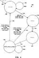
図1は、非同期バス間のインターフェイスの例を図示したものである。
図2は、図1のインターフェイスで用いられるデータ確認フラグバッファーの好ましい実施例を図示したものである。
図3は、図1の2つの同期バス間のインターフェイスであって、本発明に係る改良された同期回路に組み込まれたものを図示するものである。
図4は、図1のインターフェイス状態機械のバス2の直接関係ある部分の状態図の例を図示するものである。
図5は、図3のインターフェイス状態機械のバス2の直接関係ある部分の状態図の例を図示するものである。
好ましい実施例の詳細な説明
図1は、既知のシステムに係る互いに非同期のバス間のインターフェイス100の例を図示するものである。図1では、インターフェイスは第1のバス(バス1)110に接続されている。ここで記載された実施例では、第1のバス110は、PCI(Peripheral Component Interconnect)バスであるのが好ましい。インテル系列のマイクロプロセッサー(例えばインテル80486、インテルペンティアム、インテルP6、及びこれらに類するもの)をベースにするコンピューターのような、マイクロプロセッサーをベースとするコンピューターで利用されるPCIバス用に設立された規格に従って、PCIが動作する。基本的に第1のバス110は、第1のバスでデータを転送する複数のデータ線(バス1 データで示される)、第1のバス110で転送されたデータ用のソース又は格納先のアドレスを提供する複数のアドレス線(図示せず)、及び第1のバスでデータの転送を制御する制御信号を通信する複数の制御線(制御114で示される)を保持する32ビットデータバスである。第1のバス110は、アドレス、データ、第1のバス110の制御信号を同期するクロック信号を保持する第1のバスクロック線(バス1CLK)116も含む。例えばバス1CLK線116のクロック信号は、33MHzで動作するのが都合よい。第1のバスの動作は当業者にとって既知のものであるから、本明細書では詳細に説明しないだろう。例えば第1のバス110へのデータのソースであることが可能な周辺部の制御装置のような、コンピューターシステムの別の機器にも第1のバス110は接続される。
インターフェイスは、本明細書の実施例では例えばP6バスのような高速プロセッサーバスであるのが好ましい第2のバス120にも接続されている。好ましい実施例では、第2のバス120は、インテルP6マイクロプロセッサーと通信し、第1のバス110に関して非同期で動作する64ビットバスである。例えば、第2のバス120は、50Hz、60Hz、又は第2のバス120に接続されたP6マイクロプロセッサーのクロック周波数に関する別の周波数のいくつかで動作するのが都合がよい。本明細書では第2のバス120に関するもの記載されているが、第1のバス110に関して非同期に動作する別のプロセッサーバスが用いられてもよい。第2のバス120の特定の特性は、第2のバスのデータ転送が第1のバスのデータ転送に関して非同期を発生させることよりも、本発明に直接的に関係しない。第2のバス120は、複数のデータ線122、複数のアドレス線(図示せず)、複数の制御線124及びバス2CLK線126を含む
第1のバス110と第2のバス120との間の非同期関係が原因で、インターフィス100は、第1のバスからデータ線112を経由し、通信線114の第1のバス制御信号とバス1CLK線116のクロック信号の制御下でデータを受けるバッファー130をさらに含んでいる。データバッファー130はデータをバッファーし、さらに第2のバスからの制御線124の制御信号の制御下でバッファーされたデータをバス120へ提供し、バス2CLK線126のクロック信号に同期する。
データバッファー130は複数の格納部132を含んでいる。図1の実施例では、データバッファー0、データバッファー1、データバッファー2、データバッファー3で分類された4つの格納部132のみが示されている。以下の記載から、2つのバス間でデータの追加格納を提供するように追加格納部が含まれることが可能であることを理解すべきである。例えば特定の好ましい実施例の一つでは、8つの格納部が含まれている。示された4つの格納部のおかげで、本発明は容易に理解される。各格納部132は64のデータ信号を格納する。通常格納部132の入力は、バス1データ線112に接続されている。格納部132の出力は、64ビット4:1ワイドマルチプレクサ(MUX)134の入力として提供される。追加格納部(例えば8つ)が提供された場合、マルチプレクサは拡張され、その入力に従う追加セットを提供する(例えば、このような実施例ではマルチプレクサ134は8:1のマルチプレクサであるだろう)。マルチプレクサ134は、一対の選択線142を介してバス2インターフェイス状態機械140で制御される。特に、バス2インターフェイス状態機械140は、前もってデータが第2のバス120に転送された格納部に続いて、次に大きな番号が付けられた格納部を指示する出力ポインターを維持する。出力ポインターがデータバッファー3格納部に続いてデータバッファー0格納部を指示するように出力ポインターは、0、1、2、3、0とカウントするモジュロ4出力ポインターであることを理解すべきである。
選択線142の出力指示値に応じて、マルチプレクサ134は、出力データのソースとして4つの格納部132の1つからデータを選択し、第2のバス120と通信し、以下で検討するように選択された格納部132のデータが確認されたと想定する。選択されたデータは、通信線126のバス2CLK信号でクロックされる64ビットのワイドレジスター150に記録されるので、データは第2のバス120に同期される。さらにレジスタ150はイネーブル信号線152のイネーブル入力信号で制御される。イネーブル信号線152が非活性の場合、レジスタ150に記憶されたデータに関わらず、レジスタ150の出力は不活性である。イネーブル信号が活性である場合、レジスタ150は、複数のバス2データ線122を経由して第2のバス120に記録されたデータを出力する。バス2インターフェイス状態機械140でイネーブル線152は制御され、インターフェイス100が選択された場合のみ、レジスタ150はデータを第2のバス120に転送することが可能になる。
バス1インターフェイス状態機械160の制御下で、データは第1のバス110からデータバッファー130に格納される。バス1インターフェイス状態機械160は、第1のバス110から制御線114とバス1CLK線116とを経由する制御信号とバス1CLK信号とを受ける。バス1インターフェイス状態機械は、制御線114で通信されるデータ制御準備信号の各々に応答して、8つのデータストローブ線164の一つを経由してデータ格納部132に選択されたデータストローブを発生させる(好ましい実施の形態では、第1のバス110から各データ格納部132のそれぞれの上部及び下部に32ビットのデータをストローブするために、各データ格納部132に対して2つのデータストローブ線が設けられている)。バス1データ線112のデータが、活性されたデータストローブ線164の一つに対応するデータ格納部132の選択された一つに格納されるように、データ格納部132へのクロック信号として、データストローブ線は動作する。従来の手段でバス1インターフェイス状態機械160は動作し、環状FIFO(ファーストイン/ファーストアウト)バッファーとしてデータバッファー130を制御する。つまり、バス1インターフェイスは、データバッファー130の次に利用可能な空き格納部である入力域132の現在使用中の1つである入力ポインターを継続する。データが選択された格納部132に書き込まれた場合、入力ポインターは次に大きな番号にインクリメントする。入力ポインターが数値3からインクリメントする場合入力ポインターは0に変化するように、入力ポインターはモジュロー4ポインターである(記載された実施例では、4つの格納部を有する)。ここでは、データバッファー130は、データバッファ3に近接したデータバッファー0を備えた環状バッファーであるとみなすことができる。
バス1インターフェイス状態機械160は、複数(例えば4つ)のデータ確認フラグバッファー部を含んでいて、フラグバッファー170の各セット入力(S)への入力として提供される制御線166のセットの複数のフラグセット信号を出力する。以下の図2で詳細に記載されたように、フラグセット信号は、フラグバッファー170の各フラグ格納セルの各第1のクロック入力として提供される信号線16のバス1CLK信号と同期する。フラグバッファー170は、データバッファー130の各バッファー部(データバッファー0...データバッファー3)に対応する確認されたデータを1つ有する4つのデータフラグ(フラグ0、フラグ1、フラグ2、フラグ3)を格納する。非活性のデータ確認バッファーは、対応するバッファー部132が空きであること、かつデータがデータバッファー130に格納可能なことを示すものである。バス2インターフェイス状態機械(以下で検討するもの)に対して、活性データ確認バッファーは、対応するバッファー部のデータが第2のバス120に転送される準備がされていることも示す。データが各データバッファー部に格納された場合、データ確認フラグがセットされる。データが各データバッファー部から第2にバス120に転送された場合、データ確認フラグは消去される。
フラグバッファー170のデータ確認フラグは、データ確認フラグ線172のセットを経由して第1の4:1フラグマルチプレクサ(MUX)180に提供される。第1のフラグマルチプレクサ180は、バス1インターフェイス状態機械160からの一対のバス1選択線182で制御される。バス1インターフェイス160は一対のバス1選択線182を制御し、入力ポインターの現在値をエンコードする。このように、第1のフラグマルチプレクサ180は、入力ポインタが現在指示しているデータ格納部に対応するデータ確認フラグを選択するので、マルチプレクサ180の出力は、現在の入力部のデータが既に確認されたか否かを示すデータ確認フラグである。即ち、選択されたデータ確認フラグは、選択されたバッファー部の先に格納されたデータが既に第2のバス120に転送されたかどうか(データ確認フラグは未確認であるだろう)、選択されたデータバッファー部の先に格納されたデータは、未だ第2のバス120に転送されていないか(データ確認フラグは確認されているだろう)を示す。
フラグバッファー170のデータ確認フラグは、通信線174のシステムリセット信号を介して既知の状態(例えば全データ確認フラグが非活性である状態)にリセットされることが可能である。システムリセット信号は、コンピューターシステムの電源オンされた場合、又はコンピューターシステムがユーザーによってリセットされた場合、又はこれに類することがされた場合に発生する通常のリセット信号である。
第1のフラグマルチプレクサ180は、バス1同期フィリップフロップ192を含むデータ同期器190の入力として提供される。第1バス同期フィリップフロップ192のデータ出力は、第2のバス1同期フィリップフロップ194の入力として提供される。2つのバス1同期フィリップフロップ192、194は、クロック線116のバス1CLK信号でクロックされる。第2のバス1同期フィリップフロップの出力データは、データ確認1データ線196を経由して、バス1インターフェイス状態機械160の入力として提供される。このように、選択された確認フラグは、状態機械の入力ポインターで選択された現在のデータ格納部が新しいデータ用に利用可能であるか、又は新しいデータは受け入れられないかを示すフィードバックを提供する。別の種類の同期されたデータも利用可能であることを理解すべきである。
フラグバッファー170のデータ確認フラグは、データ確認線172のセットを経由して第2のフラグマルチプレクサ(MUX)200の入力として提供される。第2のフラグマルチプレクサ200は、バス2インターフェイス状態機械140からの一対のバス2選択線202で制御される。データバッファー130のデータ格納部132を第2のバス120に出力されるデータのソースとして選択する出力ポインター線142に対応して、バス2選択線202は制御される。従って、第2のフラグマルチプレクサ200の出力は、現在選択されたデータ格納部が確認されたデータを有するか、又はその領域のデータが既に転送されていて、もはや確認されたものでないかを示すものである。
第2のフラグマルチプレクサ200の出力は、第1のバス2同期フリップフロップ212を含むデータ確認同期器210の入力として提供される。バス2同期フリップフロップ212のデータ出力は、第2のバス2同期フリップフロップ214のデータ入力として提供される。このように現在出力ポインターが指示しているデータ格納部のデータの確認のようなフィードバックを備えている、バス2インターフェイス状態機械140が提供される。
フラグバッファー170のデータ確認バッファー部(例えばフラグ0、フラグ1、フラグ2、フラグ3)は、バス2インターフェイス状態機械140で発生させられる4つのフラグ消去線220で消去される。各フラグ消去線220は、信号線126でバス2CLKに同期するデータ確認バッファー部の各フラグ消去入力(C)として提供される。データバッファー130の各格納部からのデータが第2のバスに転送された場合、各フラグ消去線が活性される。例えば、バス2インターフェイス状態機械140が、データバッファー130のデータバッファー2格納部のデータを第2のバス120への出力データとして選択した場合、バス2インターフェイス状態機械140は、フラグ2データ確認バッファー部の消去入力(C)として提供されるフラグ消去線220に対応するものの一つを活性化させる。信号線126のバス2CLKに同期して、フラグ2データ確認バッファー部は消去される。
図2は、図1のデータ確認格納部170の好ましい実施例の一つを図示するものである。特に、図2はフラグ0データ確認格納部170Aを図示するものである。フラグ1、フラグ2及びフラグ3用の別の3つのデータ確認格納部は、フラグ0データ確認格納部と同一であるのが好ましい。記載されているように、データ確認格納部170は第1のトグルフリップフリップ300と第2のトグルフリップフロップ302とを含んでいる。
第1のトグルフリップフロップ300は、信号線116のバス1CLK信号を受けるクロック入力310を保持する。第1のトグルフリップフロップ300は、2入力の第1の論理積ゲート314の出力を受け入れるトグルイネーブル(TE)入力312を保持する。第1の論理積ゲート314は、信号線166A(図1のデータ確認フラグ線166のセットの一つであるもの)でバス1インターフェイス状態機械160からのセット確認0信号を受ける、ハイで活性する第1の入力を保持する。第1の論理積ゲート314は、信号172A(図1の信号線172の一つであるもの)からのフィードバックとして、フラグ0データ確認フラグを受ける、ローで活性する第2の入力を保持する。第1のトグルフリップフロップ300は、好ましい実施例でバス1のCLKのロー−ハイ遷移の状態を変化させる(例えば、ロー論理レベルからハイ論理レベルへ、又はハイ論理レベルからロー論理レベルへ)Q出力316を保持する。フラグ0データ確認フラグが非活性であるのと同時に、信号線166Aのセット確認0信号が活性である場合のみ、第1のトグルフリップフロップ300のQ出力信号は変化する。セット確認0信号が活性され、かつフラグ0データ確認フラグが不活性の場合、論理積ゲート314の出力は活性であり、さらに第1のトグルフリップフロップ300のQ出力は、バス1CLK信号が各ロー−ハイ遷移する時間で、ハイ状態からロー状態へ、又はロー状態からハイ状態へ変化する。セット確認0信号が不活性である、フラグ0データ確認フラグが活性であるのどちらか一方である場合、第1のトグルフリップフロップ300のQ出力は、バス1CLK信号の変化によって変化しないであろう。
第2のトグルフリップフロップ302は、信号線126のバス2CLK信号を受けるクロック入力330を保持する。第2のトグルフリップフロップ302は、2入力の第2の論理積ゲート334の出力を受けるトグルイネーブル(TE)入力332を保持する。第2の論理積ゲート334は、バス2インターフェイス状態機械140からの信号線220A(図1のデータ確認フラグ消去線220一つであるもの)で消去確認0信号を受ける、ハイで活性する第1の入力を保持する。第2の論理積ゲート334は、信号172Aのフィードバックとして、フラグ0データ確認フラグを受ける、ハイで活性する第2の入力を保持する。第2のトグルフリップフロップ302は、好ましい実施例でバス2のCLKのロー−ハイ遷移の状態(例えば、ロー論理レベルからハイ論理レベルへ、又はハイ論理レベルからロー論理レベルへ)を変化させるQ出力336を保持する。フラグ0出力信号が活性であるのと同時に、信号線220Aの消去確認0信号が活性である場合のみ、第2のトグルフリップフロップ302のQ出力信号は変化する。消去確認0信号が活性で、かつフラグ0データ確認フラグが活性の場合、論理積ゲート334の出力は活性であり、さらに第1のトグルフリップフロップ302のQ出力は、バス2CLK信号が各ロー−ハイ遷移する時間で、ハイ状態からロー状態へ、又はロー状態からハイ状態へ変化する。消去確認0信号が不活性である、フラグ0データ確認フラグが活性であるのどちらか一方である場合、バス2CLK信号の変化に関わらず、第2のトグルフリップフロップ302のQ出力は変化しないであろう。
第1のトグルフリップフロップ300はリセット(RST)入力340を保持し、さらに第2のトグルフリップフロップ302はリセット(RST)入力342を保持する。RST入力340、342は、信号線340でシステムリセット信号を受ける。システムリセット信号が活性の場合、2つのトグルフリップフロップ300、302はリセットされ、各Q出力は消去されて非活性ロー状態になる。
第1及び第2のトグルフリップフロップ300、302のQ出力は、それぞれ排他的論理和ゲート350の第1の入力、第2の入力として提供される。排他的論理和ゲート350の出力は、フラグ0データ確認格納部の出力である通信線172Aにフラグ0データ確認フラグを提供する。先に検討したように、通信線172Aのフラグ0データ確認フラグは、各論理積ゲート314、334を経由する2つのトグルフリップフロップ300、302のフィードバックとしても提供される。出力Qが互いに異なる場合(例えば一方のQ出力がハイ活性で、別のQ出力がロー活性である場合)、排他的論理和ゲート350は、2つの入力に応答して動作して、通信線172Aに活性フラグ0データ確認フラグを提供し、さらに2つのQ出力が同じ場合(例えば両Q出力がハイ活性の場合、又は両Q出力がロー活性である場合)には、通信線172Aに不活性フラグ0データ確認フラグが提供される。先に検討したように、排他的論理和ゲート350の出力が、第2のトグルフリップフロップ302のQ出力が第1のトグルフリップフロップ300の出力Qと異なることを示すハイ活性である場合のみ、消去確認0信号線220Aが活性である場合に第2のトグルフリップフロップ302が使用可能であるように、第2の論理積ゲート334が潜在的に使用可能になる。第2のトグルフリップフロップ302は、信号線126のバス2CLK信号の次のロー−ハイ遷移をトグルする。このことで、第2のトグルフリップフロップ302の出力Qが第1のトグルフリップフロップ300の出力Qと同じになり、排他的論理和ゲート350の出力が非活性になる。排他的論理和ゲート350の非活性状態は、フラグ0が消去されたこと(例えばデータが非活性であること)を示す。さらには、第2のトグルフリップフロップ302はトグルが不可能であり、またバス1インターフェイス状態機械160によってセット確認0シグナル線166Aが活性される場合、第1のトグルフリップフロップ300はトグル可能である。フラグ0データ確認フラグは、バス1CLK信号と同時にセットされ、かつバス2CLK信号と同時に消去される。
米国特許第5,083,049号を例とする格納部に基づくトグルフリップフロップに関する追加情報は先に説明され、本発明の応用に割り当てられ、本明細書に参照として組み込まれている。当業者は、本発明に関してもう一つのデータ確認格納部が用いられることを認識するだろう。
再度図1を参照にする。バス1データ確認同期器190とバス2データ確認同期器210との目的は、2つの状態機械を制御する各クロックと同期して、データ確認フラグの遷移がバス1インターフェイス状態機械160とバス2インターフェイス状態機械140とに提供されることを保証することであることが理解できる。特に先に検討したように、データ確認フラグはバス1CLK信号と同期してセットされ、バス2CLK信号と同期して消去される。このように、データ確認フラグは、バス1CLK信号に同期して非活性状態から活性状態に変化するであろう、さらにバス2CLK信号に同期して活性状態から非活性状態に変化するだろう。バス1CLK信号は、バス2CLK信号に非同期であるから、バス1インターフェイス状態機械160は、内部的な状態変化に対する非同期のデータ確認フラグの活性ー非活性変化を受け入れる。このように、バス1インターフェイス状態機械が安定させ変化させないデータ確認フラグの状態を要求する一方で、遷移が発生する可能性がある。バス1同期器190は、データ確認フラグのロー−ハイ遷移をバス1CLKに同期し、バス1インターフェイス状態機械160の内部遷移状態を同期する。同様にバス2同期器210は、データ確認フラグのロー−ハイ遷移をバス2CLKに同期し、こうしてバス2インターフェイス状態機械140の内部遷移状態に同期する。データが現在選択された入力部に書き込まれるように各データ確認フラグがセットされるので、データ確認フラグの遷移はバス2CLKに同期することが特に重要である。現在選択された入力部が、現在選択された出力部でもある場合(例えば、バス2インターフェイス状態機械140が前述の全格納データを保持する場合)、バス2インターフェイス状態機械140は、データ確認フラグが活性され第2のバス120へのデータを出力することを即座に感知する。しかしながら、特にデータが各データ格納部に格納され、マルチプレクサ134とレジスタとを介して伝搬される前に、データ確認フラグが非活性から活性へ遷移する場合、このポテンシャルがバス2インターフェイス状態機械140内部の準安定状態を引き起こす。バス2同期器は、バス2インターフェイス状態機械140が第2のバス120にデータを出力する前にデータが安定することを保証する。
図1のバス1からバス2へのインターフェイス100は、所望の目的用に優れて動作する。しかしながら、バーストモードにおいてデータがインターフェイス100から転送される、又はインターフェイス100に転送される場合、インターフェイス100は、インターフェイス100の全データ速度を低減するバス1同期器190とバス2同期器210で発生する同期遅延を含む。データバッファー130の全4つのデータバッファー部(データバッファー0...データバッファー3)が満たされ、かつ対応するデータ確認フラグ(フラグ0...フラグ3)がセットされている場合のバス2インターフェイス状態機械140の動作を考慮することで、この問題が理解されることができる。バス2インターフェイス状態機械140が第1のデータ格納部(例えばデータバッファー0)からデータを転送した後、バス2インターフェイス機械140は、マルチプレクサ134を経由して次のバッファー部(例えばデータバッファー1)を選択し、さらに第2のフラグマルチプレクサ200への選択線202を経由してデータ確認フラグ(例えばフラグ1)も選択する。第2のバッファー部(データバッファー1)のデータが多量のクロック周期に安定しているが、バス2インターフェイス状態機械140が第2のバス120にデータを出力するまで、バス2インターフェイス状態機械140はバス2同期器210に同期されるデータ確認フラグを待たなければならない。このように、バス2CLK信号の不必要な2つのサイクルは同期されたデータ確認フラグに割り込む。
バス1インターフェイス状態機械が入力ポインターを次の部分にインクリメントする場合、同様の不必要な遅延が割り込む。バス1インターフェイス状態機械が第1のフラグマルチプレクサ180への選択線182を遷移させる場合、次のデータ格納部がクロック周期に対して空きであってもよいが、バス1インターフェイス状態機械が、データ確認フラグが消去されること、及びデータ格納部が利用可能であることを決定する前に、バス1インターフェイス状態機械がバス1同期器180に同期される選択されたフラグ用の2つのクロック周期を待たなければならない。
データ確認フラグをバス2フラグマルチプル200に適用される前に、データ確認フラグを同期することで、不必要な遅延が除去することが可能なことを応用例は発見した。改良されたインターフェイスは図3に図示されていて、ここでは先に記載された図1と同じ参照番号は同じ要素を示す。バス2インターフェイス状態機械140が改造され、図3のバス2インターフェイス状態機械404として示される。同様に、バス1インターフェイス状態機械160が改造され、図3のバス1インターフェイス状態機械406として示される。
図3で示されたように、図1の第1のフラグマルチプル180の出力の1つのバス1同期器190は、4つのバス1同期器410、412、414及び416を備えて再設置される。各バス1同期器410、412、414及び416は、4つのデータ確認フラグバッファー部170のそれぞれ一つに接続された各入力と、第1のフラグマルチプレクサ180の入力に接続された各出力とを保持する。第1のバス1同期器410にさらに図示されているように、各同期器は、タンデムで接続され、信号線116のバス1CLK信号でクロックされる一対のフリップフロップ420と422を含む。
同様に、一つのバス2同期器210は、4つのバス1同期器430、432、434及び436を備えて再設置される。各バス2同期器430、432、434及び436は、4つのデータ確認フラグバッファー部170のそれぞれ一つに接続された各入力と、第2のフラグマルチプレクサ200の入力に接続された各出力とを保持する。第1のバス2同期器430にさらに図示されているように、各同期器は、タンデムで接続され、信号線126のバス2CLK信号でクロックされる一対のフリップフロップ440と442とを含む。
データ確認フラグが、バス1インターフェイス機械406とバス2インターフェイス機械404とに適切に同期されることを保証することで、改良されたインターフェイス400が図1のインターフェイスの目的を達成する。例えば、バス2インターフェイス状態機械404は、データバッファー130の全データ出力を保持し、格納部132に格納される次のデータを待つ場合、入力ポインター及び出力ポインターは同じ格納部132を指示するだろう。バス1インターフェイス状態機械がデータ確認フラグ(例えばフラグ0)をセットした場合、フラグ0フラグバッファー170A(図2)の出力は遷移され活性状態になり、第1のバス2同期器430を経由して伝達され、出力がバス2インターフェイス状態機械404の活性された入力として適用させる前にバス2インターフェイス状態機械404に同期させられるだろう。フラグ0フラグバッファー170Aの活性出力はバス2クロックを同期するのに必要であり、このようにバス2インターフェイス状態機械404に同期される。フラグ0フラグバッファー170Aの活性された出力は遅延され、データバッファー0データ格納部132に格納させ、安定されることを可能にする必須時間を提供する。他方、バス2インターフェイス状態機械がデータバッファー130から集中的にデータも出力していて、さらに次に選択されるべきバッファー部132が多数のクロック周期のために格納されたデータを有する場合、データ確認フラグは各バス2同期器(例えば第2のバス2同期器432)を経由して伝達され、第2のフラグマルチプレクサ200の入力で活性されるだろう。従って、バス2インターフェイス状態機械は選択線202を変更してフラグ1データ確認バッファーを選択する場合、フラグの活性状態は、遅延なく、即座にバス2インターフェイス状態機械404に提供される。
図3の改良されたインターフェイスをさらに理解することを補助するため、図4は図1のバス2インターフェイス状態機械140に直接関係する部分の例的な状態図500を示し、図5は図3のバス2インターフェイス状態機械404に直接関係する部分の例的な状態図510を示すものである。各状態機械140、404は、本発明に直接関係する部分でなく、ここでは説明されていない、図4と5に示されない付加的な機能を含んでいる。図4と5においては、状態機械の適切な内部状態は、状態名を有する円によって従来の手段で示される。円をつなぐ線は、一つの状態から別の状態へ、又は図1と2のバス2CLK信号126に同期する状態からそれ自身へ戻る遷移状態を示すものである。
遷移状態を発生させる為にアンパサンドで結合された全条件が満たされなくてはならないことを意味するANDを示すアンパサンド(”&”)を有する各遷移状態に隣接して配置されたパラメータと遷移状態に先立つ条件は同一である。条件の上のラインは条件が不活性でなくてはならないことを示す。遷移状態に隣接する”1”は、バス2CLK信号の次の周期の発生時、一つの状態から次の状態への遷移が無制限を発生することを示すものである。遷移状態の横の”ELSE”は、遷移状態が、与えられた状態から別の遷移への条件が満足されない場合に発生するデフォルト遷移であることを示す。特定の遷移の発生時にバス2インターフェイス状態機械140が適切な動作を実行する場合の各動作は動作名が続いているスラッシュ(”/”)されたパラメータとの同一である
図4で示されたように、状態図500は、アイドル状態520、マスク1状態522、DATA_XFR_IN_PROG(データ転送進行)状態526を含む。状態図500は、データバッファー132から第2のバスへのデータの多重カッド語の遷移の進行を示す。アイドル状態520は、バス2状態機械140の通常状態であり、リセット遷移状態530で図示されたように、コンピューターシステムがリセットされた場合に入る状態である。以下で検討するように、データ転送が完了した場合、バス2インターフェイス状態機械140はアイドル状態520に戻る。
第2のバス120の制御信号と、いつ新しい読み込み周期が開始されるかを決定する条件とをモニターするバス2インターフェイス状態機械140の別の部分によって新しい周期が開始されない限り、バス2インターフェイス状態機械140はアイドル状態520に維持される。新しい読み出し周期が開始されるまで、アイドル状態に維持されたバス2インターフェイス状態機械140の動作は、ELSE遷移状態532で示されたバス2状態機械140のこの部分がバス2状態機械140の別の部分をモニターし、いつ新しい読み出しサイクルが開始されるかを決定する。特に、バス2インターフェイス状態機械140はアイドル状態520に維持される一方、内部のNEW_RD信号は非活性である。
バス2インターフェイス状態機械によって新しい読み出しサイクルが開始され(NEW_RDが活性である)、かつバス2インターフェイス状態機械がバスインターフェイス100に割り当てられた(BUS_RD_TIMEで示された信号が活性である)場合、バス2インタフェイス状態機械140は、マスク状態522への遷移状態540をつくる。遷移状態パラメーターの”/LOAD_QW_CNT”部でさらに記載されているように、バス2インターフェイス状態機械はカッド語カウントをロードし、遷移状態が発生した場合のカッド語カウンター(図示せず)に至る。カッド語カウントは、第1のバス110から第2のバス120へ多数の与えれたデータの転送を発生させなくてならない転送数を示す。
マスク1状態522とマスク2状態524とは遅延状態であり、バス2インターフェイス状態機械140が選択されたデータ確認フラグの状態を確認する前に、選択されたデータ確認フラグは、バス2フラグマルチプル200からバス2同期器210を経由して伝達されるのに十分な時間を保持する。従って、マスク1からマスク2への遷移542は、条件を発生しないように記載されている(近接するパラメーター1で示されている。同様に、マスク2状態からDATA_XFR_IN_PROGへの遷移544も条件を発生しない)。
DATA_XFR_IN_PROG状態526では、バス2インターフェイス状態140は、DATA_VALID_2フラグを確認し、それが活性でない場合、バス2インターフェイス状態機械は,ELSE遷移550によって、DATA_XFR_IN_PROG状態526に維持される。別の方法では、DATA_VALID_2フラグが活性でかつBUS_RD_TIMEが活性である場合、バス2インターフェイス状態機械140は、それぞれが遷移552又は遷移554を経由して、アイドル状態520又はマスク1状態522のいずれかに遷移し、現在選択されているバッファー部132の一つにデータを出力するだろう。このことは、遷移552と554の両方で/OUT_DATAパラメータで図示されている。データを出力することに加えて、バス2インターフェイス状態機械がフラグバッファー170の一つに対応するCLR_VALID信号を活性させる。
遷移552又は遷移554を選択することは、DONEパラメータの状態に依存する。DONEパラメータは、カッド語カウンターのQW_CNT出力の状態を示すものである。QW_CNTがゼロでない数値を保持する場合、DONEは非活性である
![]()
![]()
選択されたデータバッファー部132に格納される出力バッファー部の新しく選択されたデータの大きさ、及び対応する活性されたデータ確認フラグの大きさに関わらずに、この遅延は割り込むであろう。
図1で記載されたようなマルチプル200の後に記載された一つのバス同期器210のみを保持するよりもむしろ、図3で記載されたようにバス2フラグマルチプレクサ200の入力とフラグバッファー170の出力との間にマルチプルバス2同期器430、432、434及び436が設置されていることが原因で、図4の状態図500とは対照的に、図5の状態図510は、より少ない状態とより効果的な動作を必要とする。特に、図5の状態図510は、アイドル状態600とDATA_XFR_IN_PROG状態610のみを含む。先に検討したようにアイドル状態600にはリセット遷移620で入る。DATA_XFR_IN_PROG状態610への遷移62に隣接するパラメータで記載されたような一定の条件を満たすまで、ELSE遷移で記載されたように図3のバス2インターフェイス状態機械404は、アイドル状態600に維持されるであろう。特にNEW_RDが開始され、かつBUS_RD_TIME条件が活性になるまで、バス2インターフェイス状態機械404はアイドル状態に維持されるであろう、バス2インターフェイス状態機械404は、遷移状態624を経由してDATA_XFR_IN_PROG状態610に遷移し、/LOAD_QW_CNTパラメータで示されるようにカッド語の数を転送するカッド語カウンターをロードするだろう。
DATA_XFR_IN_PROG状態610では、バス2インターフェイス状態機械404は、DATA_VALID_2信号の状態をモニターする。DATA_VALID_2信号が活性でかつ、BUS_RD_TIMEが活性を維持する場合、バス2インターフェイス状態機械404は、DONE状態に関する2つの遷移状態630と632の一つのを実行するだろう。DONE状態が非活性の場合、バス2インターフェイス状態機械404は、遷移状態630で記載されたようなDATA_XFR_PROG状態に維持され、/OUT_DATAパラメータで記載されているように現在選択されているデータバッファー部132の中身を出力する。バス2インターフェイス状態機械404は、現行のバッファー数(/INC_BUF_NUM)をインクリメントし、カッド語カウンター(/DEC_QW_CNT)をデクリメントする。DONE状態が活性である場合、バス2インターフェイス状態機械404は、遷移状態632を経由してアイドル状態600に戻る一方、最後のカッド語(/OUT_DATA)を出力し、バッファー番号(INC_BUF_NUM)をインクリメントする。DATA_VALID_2信号が活性でない場合、又はBUS_RD_TIME状態が合致しない(例えば、第2のバス120が現行で利用できない場合)場合、バス2インターフェイス状態機械404は、ELSE遷移634で記載されたようにDATA_XFR_IN_PROG状態610に維持される。
状態図510で記載されたように、図3と5に関するバス2インターフェイス状態機械404は、図1と4のバス2インターフェイス状態機械140の固有の時間遅延を保持しない。特に、バス2インターフェイス状態機械404が遷移状態630でバッファー番号をインクリメントするやいなや、バス2インターフェイス状態機械404はDATA_XFR_IN_PROG状態610にとどまり、即座にDATA_VALID_2信号を確認し、新しく選択されたバッファー部132からデータが出力が可能か否かを決定する。対応するデータ確認フラグ(フラグ0、フラグ1、フラグ2又はフラグ3)が各バス2同期器430、432、434又は436を経由して伝達され、フラグマルチプレクサ200の次の入力が選択されると直ぐに、フラグマルチプレクサ200への入力が可能となるので、上記のことが発生することができる。このように、第2のバス120がバス2インターフェイス状態機械404に割り当てられて維持されることが保証され、第1のバスがデータバッファー部132で満たされることが保証されるので、データは、各出力間に2つのクロック周期遅延を割り込ませなくてはならないことよりもむしろ、連続する各クロック周期のバッファー部132から出力されることが可能になる。
本発明の特定の実施例に関して先に記載されているが、実施例の記載は本発明の例示であり、制限を目的とするものではないことを理解すべきである。添付の請求項で定義された本発明の真の範囲と思想から離れることなく、当業者によって様々な変形と応用が思い起こされていてもよい。Background of the invention
TECHNICAL FIELD OF THE INVENTION
The present invention relates to general computer systems, and more particularly to a digital subsystem that controls the transfer of data from one synchronous data bus to another synchronous bus that are asynchronous with each other.
Disclosure of related technology
Most modern computer systems maintain multiple different data buses that operate at different data rates. In some systems, different data rates can be associated with one of the common clocks so that the different data buses operate synchronously with each other. However, in many systems, the different data buses operate asynchronously with respect to each other. That is, different data buses are controlled by different clocks, and there is no fixed relationship between the frequency and phase of different clocks. Accordingly, the data on the source bus is irregularly converted with respect to the control signal of the storage bus to which the data is transferred. This is because the holding time and minimum setup time of a digital device such as a register or another storage device must be met, and data transfer synchronization between the two buses is required. This is achieved with a synchronous circuit. For example, the source bus generates a data strobe signal to indicate that the source bus data is ready to be transferred. The normal data strobe signal cannot be used to directly control the storage bus. Rather, by clocking the data strobe signal to the clock that controls the storage bus, the data strobe signal is initially held in a control circuit coupled to the storage bus. The retained data strobe signal is then used to control the storage device (eg, register, latch) of the storage bus. By synchronizing the data strobe signal (or control signal) to the storage bus, it can be ensured that the data from the source is stabilized and transferred to the storage bus.
Although data strobe signals that guarantee data transfer between two asynchronous buses can be generated without losing data, there is a procedure time for synchronization. In particular, synchronization may take as much time as two storage bus clock cycles. For occasional data transfer, the synchronization procedure time can easily be tolerated, but when a large amount of data is transferred by multiple transfer (eg burst transfer), the accumulated procedure time is the computer system There is plenty of potential to reduce the overall capacity of the. Therefore, there is a need to reduce the synchronization procedure time for burst transfer of data between two asynchronous buses.
Summary of the invention
One aspect of the present invention is an interface circuit between the first and second buses operating asynchronously with each other. The first bus provides data to the interface circuit synchronized to the first bus clock, and the second bus receives data from the interface circuit synchronized to the second bus clock. The apparatus includes an input / output buffer that holds at least first and second buffer units in which data from the first bus is stored in synchronization with the first bus clock. At least the first and second data confirmation indicators are first and second buffer units, respectively. When data is stored in the first buffer unit, the first data display is set in synchronization with the first bus clock. When the data is stored in the second buffer unit, the second data display is set in synchronization with the second bus clock. The selector of the data confirmation indicator selects one of the first and second data confirmation indicators as the output of the data confirmation indicator. The bus state machine transfers data from the I / O buffer to the second bus in synchronization with the second bus clock. As a source of data transferred to the second bus, the bus state machine selects one of the first and second buffer sections. The bus state machine controls the selector of the data confirmation indicator and selects one each of the first and second data confirmation indicators as the data confirmation indicator output. The bus state machine monitors the data confirmation indicator output to determine when to store the data from the first bus in the selected first or second buffer section. The first synchronization circuit receives the first data confirmation indicator, synchronizes it to the second bus clock, and provides a first data confirmation indicator synchronized as the input of the selector of the data confirmation indicator. The second synchronization circuit receives the second data confirmation indicator, synchronizes it to the second bus clock, and provides a second data confirmation indicator synchronized as the input of the selector of the data confirmation indicator.
Another aspect of the present invention is an apparatus for transferring data between first and second buses operating asynchronously with each other. The apparatus includes a plurality of data storage units that store data. The first bus interface state machine is connected to the first data bus. The first bus state machine transfers data from the first bus to a selected one of the plurality of data stores. The second bus interface state machine is connected to the second data bus. The second bus state machine transfers data from the selected one of the plurality of data storage units to the second data bus. A current data buffer holding a display for each of the plurality of data stores is included. One of the indicators is set in response to a first bus indicator that transfers data to a selected one of a plurality of data portions, and from a selected one of a plurality of data areas to a second bus. Erased in response to the second bus state machine transferring the data. Only when the selected indicator is set, the second bus interface state machine transfers data from the selected one of the plurality of data stores. Each set of delay circuits is connected between the current data buffer and the second bus interface state machine to delay the display so that after the bus interface machine transfers the data to the selected data store The second bus interface state machine may not be transferred from one of the plurality of data stores before the predetermined time has elapsed.
Another aspect of the present invention is an apparatus for transferring data on a first bus and a second bus. The first and second data buses operate asynchronously with each other. The apparatus includes a buffer that holds first and second data storage units for storing data. The first bus state machine is connected to the first data bus and transfers data from the first data bus to the selected one of the first and second data stores for the first bus clock signal. Control. The second bus interface state machine is connected to the second data bus and controls the transfer of data from the buffer to the second data bus with respect to the second bus clock signal operating asynchronously with the first bus clock signal. . The first and second flag buffers have first and second flag outputs each connected to both the first and second interface state machines. The first flag buffer is set in synchronization with the first bus clock signal when data is transferred from the first data bus to the first data storage unit, and the data is transferred from the first data storage unit to the first data buffer. When it is transferred to the second data bus, it is erased in synchronization with the second bus clock signal. The second flag buffer is set in synchronization with the first bus clock signal when data is transferred from the first data bus to the second data storage unit, and the data is transferred from the second data storage unit to the second data buffer. When it is transferred to the second data bus, it is erased in synchronization with the second bus clock signal. The first synchronizer is connected between the first flag buffer and the second bus interface machine. The second synchronizer is connected between the second flag buffer and the second bus interface machine. The first synchronizer synchronizes the first flag output to the second bus clock signal so that the first flag output is accepted by the second bus interface state machine after the first flag output changes. Before it becomes possible, the first flag output is delayed for at least a predetermined time. The second synchronizer synchronizes the second flag output to the second bus clock signal so that the first flag output is accepted by the first bus interface state machine after the second flag output changes. Before it can, the second flag output is delayed for at least a predetermined time.
[Brief description of the drawings]
The present invention is described below with reference to the accompanying drawings.
FIG. 1 illustrates an example of an interface between asynchronous buses.
FIG. 2 illustrates a preferred embodiment of the data confirmation flag buffer used in the interface of FIG.
FIG. 3 illustrates the interface between the two synchronization buses of FIG. 1 that is incorporated into the improved synchronization circuit of the present invention.
FIG. 4 illustrates an example state diagram of the directly related portion of the
FIG. 5 illustrates an example state diagram of the directly related portion of the
Detailed Description of the Preferred Embodiment
FIG. 1 illustrates an
The interface is also connected to a
Due to the asynchronous relationship between the
The
Depending on the output indication value on
Under control of the
The
The data confirmation flag in the
The data confirmation flag in the
A
The data confirmation flag in the
The output of the
The data confirmation buffer portion of flag buffer 170 (eg, flag 0,
FIG. 2 illustrates one preferred embodiment of the
The first toggle flip-
The second toggle flip-
The first toggle flip-
The Q outputs of the first and second toggle flip-
Additional information regarding toggle flip-flops based on storage, taking US Pat. No. 5,083,049 as an example, has been previously described, assigned to the application of the present invention and incorporated herein by reference. One skilled in the art will recognize that another data validation store is used in connection with the present invention.
Please refer to FIG. 1 again. The purpose of the
The
A similar unnecessary delay interrupts when the
Application examples have found that unnecessary delays can be eliminated by synchronizing the data confirmation flags before they are applied to the
As shown in FIG. 3, one
Similarly, one
By ensuring that the data confirmation flag is properly synchronized to the
To assist in further understanding the improved interface of FIG. 3, FIG. 4 shows an exemplary state diagram 500 of the portion directly related to the
Parameters and transition states placed adjacent to each transition state with an ampersand ("&") indicating AND, which means that all conditions joined by the ampersand must be met to generate the transition state The conditions prior to are the same. The line above the condition indicates that the condition must be inert. “1” adjacent to the transition state indicates that an unlimited transition from one state to the next occurs when the next period of the bus 2CLK signal occurs. “ELSE” next to the transition state indicates that the transition state is a default transition that occurs when a condition from a given state to another transition is not satisfied. When the
As shown in FIG. 4, the state diagram 500 includes an
Unless the new cycle is initiated by another part of the
If a new read cycle is initiated by the
In the
Selecting
![]()
![]()
This delay will interrupt regardless of the size of the newly selected data in the output buffer portion stored in the selected
Rather than holding only one
In the DATA_XFR_IN_PROG state 610, the
As described in state diagram 510,
Although described above with respect to particular embodiments of the present invention, it should be understood that the description of the embodiments is illustrative of the invention and is not intended to be limiting. Various modifications and applications may occur to those skilled in the art without departing from the true scope and spirit of the invention as defined in the appended claims.
Claims (6)
上記第1のバスクロックに同期して、上記第1のバスからのデータを格納する第1と第2のバッファー部とを少なくとも有する入出力バッファーと、
上記入出力バッファーから第2のバスにデータを転送し、上記第2のバスクロックと同期して動作するバス状態機械と、
上記第1と第2のバッファー部のそれぞれに関連して、データ格納を表示するための第1と第2のデータ確認表示器と、
データ確認表示出力として、上記第1と第2のデータ確認表示器から一つを選択するデータ確認表示器セレクターと、
上記第1のデータ確認表示器の出力を受けて、該出力を上記第2のバスクロックに同期させ、上記データ確認表示器セレクターの入力として第1の同期したデータ確認表示器を提供する第1の同期回路と、
上記第2のデータ確認表示器の出力を受けて、該出力を上記第2のバスクロックに同期させ、上記データ確認表示器セレクターの入力として第2の同期したデータ確認表示器を提供する第2の同期回路とを備え、
上記第1のデータ確認表示器は、上記第1のバッファー部にデータが格納された場合に上記第1のバスクロックに同期してセットされ、
上記第2のデータ確認表示器は、上記第2のバッファー部にデータが格納された場合に上記第1のバスクロックに同期してセットされ、
上記バス状態機械は、データ確認表示出力に基づいて上記第2のバスに転送されるデータのソースとして上記第1と第2のバッファー部のうち一つを選択し、データ確認表示出力として上記第1と第2のデータ確認表示器の各1つを選択するように上記データ確認表示器セレクターを制御し、上記第1のバスからのデータが上記第1と第2のバッファー部のうち選択した一つに格納されたか否かを示す上記データ確認表示器出力をモニターするものであり、
各第1および第2の同期回路は、個々のデータ確認表示器出力がデータ確認表示器セレクターへ入力される前は個々の同期を実行するようにし、データ確認表示器セレクターが第1および第2のデータ確認表示器出力の間の選択を変化させた後、変化したデータ確認表示器出力がバス状態機械に提供されるまでは、更なる同期を要しないように構成されており、
第1および第2の同期回路は、互いに並列に配置され、個々の同期は、第1および第2の同期回路によって実質的に同時にそれぞれ実行されるようにしたインターフェイス回路。An interface circuit between a first bus and a second bus that operate asynchronously with each other, wherein the first bus provides data to the interface circuit in synchronization with a first bus clock, and in 2 of the bus interface circuit to accept said data from said interface circuit in synchronism with the second bus clock,
An input / output buffer having at least first and second buffer units for storing data from the first bus in synchronization with the first bus clock;
A bus state machine that transfers data from the I / O buffer to a second bus and operates in synchronization with the second bus clock;
First and second data confirmation indicators for displaying data storage in relation to each of the first and second buffer sections;
As a data confirmation display output, a data confirmation display selector for selecting one of the first and second data confirmation displays;
Receiving an output of said first data confirmation indicator, the output is synchronized with the second bus clock, the providing a first synchronized data confirmed indicator as an input of the data confirmation indicator selector 1 synchronization circuit ;
Receives the output of the second data confirmation indicator, the output is synchronized with the second bus clock, the providing a second synchronized data confirmed indicator as an input of the data confirmation indicator selector Two synchronization circuits ,
The first data confirmation indicator is set in synchronization with the first bus clock when data is stored in the first buffer unit,
The second data confirmation indicator is set in synchronization with the first bus clock when data is stored in the second buffer unit.
The bus state machine selects one of the first and second buffer units as a source of data to be transferred to the second bus based on a data confirmation display output, and uses the first as a data confirmation display output. Controlling the data confirmation indicator selector to select one of each of the first and second data confirmation indicators, and the data from the first bus selected from the first and second buffer units; The data confirmation indicator output indicating whether or not it is stored in one is monitored,
Each of the first and second synchronization circuits performs an individual synchronization before the individual data confirmation indicator output is input to the data confirmation indicator selector, and the data confirmation indicator selector has the first and second data confirmation indicators. After changing the choice between the data validation indicator outputs, it is configured to require no further synchronization until the altered data validation indicator output is provided to the bus state machine,
An interface circuit in which the first and second synchronization circuits are arranged in parallel to each other, and the individual synchronizations are performed substantially simultaneously by the first and second synchronization circuits, respectively.
データを格納する複数のデータ格納部を備えるデータ保持装置と、
上記第1のデータバスに接続され、上記第1のデータバスから上記複数のデータ格納部のうち選択された一つにデータを転送する第1のバスインターフェイス状態機械と、
上記第2のデータバスに接続され、上記複数のデータ格納部のうち選択された一つから上記第2のデータバスにデータを転送する第2のバスインターフェイス状態機械と、
上記複数のデータ格納部用に個々の表示器を有するデータ存在バッファーと、
上記データ存在バッファーと上記第2のバスインターフェイス状能機械との間に接続され、上記表示器を遅延させるための各遅延回路のセットと、
上記表示器の一つを選択し、選択した表示器が第2のバスインターフェイス状態機械に提供されるようにした各遅延回路の出力に接続された表示器セレクターとを備え、
データ存在バッファーにおける上記表示器の一つは、上記複数のデータ格納部の上記一つにデータを転送する上記第1のバス状態機械に応答してセットされ、かつ上記複数のデータ格納部から上記第2のデータバスへデータを転送する上記第2のバス状態機械に応答して消去され、上記表示器の上記一つがセットされた場合のみ、上記第2のバスインターフェイス状態機械が上記複数のデータ格納部の上記一つからデータを転送するものであり、
各遅延回路のセットは、上記第1のバスインターフェイス機械が上記複数のデータ格納部の上記一つにデータを転送した後で所定の時間が経過するまでは、上記第2のバスインターフェイス状態機械が上記複数のデータ格納部の上記一つからデータを転送しないようにするものであり、
各遅延回路のセットは、第1および第2の同期回路を備えており、
各第1および第2の同期回路は、個々の表示器が表示器セレクターへ入力される前は個々の同期を実行するようにし、表示器セレクターが1つの表示器から他の表示器までの選択を変化させた後、変化した表示器が第2のバス状態機械に提供されるまでは、更なる同期を要しないように構成されており、
第1および第2の同期回路は、互いに並列に配置され、個々の同期は、第1および第2の同期回路によって実質的に同時にそれぞれ実行されるようにした装置。An apparatus for transferring data between a first bus and a second bus that operate asynchronously with each other,
A data holding device comprising a plurality of data storage units for storing data;
Connected to said first data bus, the first bus interface state machine to transfer data to the selected one of said plurality of data storage unit from the first data bus,
Connected to said second data bus, a second bus interface state machine transferring data from a selected one of said plurality of data storage unit to the second data bus,
A data presence buffer having individual indicators for the plurality of data storage units ;
A set of delay circuits connected between the data presence buffer and the second bus interface state machine for delaying the display ;
An indicator selector connected to the output of each delay circuit for selecting one of the indicators and causing the selected indicator to be provided to a second bus interface state machine;
One of the indicators in the data presence buffer is set in response to the first bus state machine transferring data to the one of the plurality of data storage units, and from the plurality of data storage units to Only when the one of the indicators is set is erased in response to the second bus state machine transferring data to a second data bus, the second bus interface state machine is the plurality of data Transferring data from one of the storage units,
Each set of delay circuits is configured so that the second bus interface state machine has a predetermined time after the first bus interface machine transfers data to the one of the plurality of data storage units. The data is not transferred from the one of the plurality of data storage units,
Each delay circuit set includes first and second synchronization circuits;
Each first and second synchronization circuit allows individual synchronization to be performed before each individual display is input to the display selector, and the display selector selects from one display to the other display. Is changed so that no further synchronization is required until the changed indicator is provided to the second bus state machine,
An apparatus in which the first and second synchronization circuits are arranged in parallel with each other and the individual synchronizations are performed substantially simultaneously by the first and second synchronization circuits, respectively.
上記装置は、さらに、上記バスインターフェイス状態機械に対して上記表示器を遅延させる上記データ存在バッファーと上記第1のインターフェイス状態機械との間に接続された遅延回路の第2のセットを含んでおり、
上記第2のバスインターフェイス機械は、上記複数のデータ格納部の上記一つから上記第2のデータバスにデータを転送した後で第2の所定の時間が経過するまでは、上記第1のバスインターフェイス状態機械が、上記複数のデータ格納部の一つにデータを転送しないようにした請求項2記載の装置。A first set of said set of delay circuits delay circuit, the predetermined time is a first predetermined time,
The apparatus further includes a second set of connected delay circuits between the data present buffer and said first interface state machine to delay the indicators with respect to the bus interface state machine ,
It said second bus interface machine, to a second predetermined time after transmitting the data to the second data bus from said one of said plurality of data storage unit has elapsed, the first bus 3. The apparatus of claim 2, wherein the interface state machine does not transfer data to one of the plurality of data stores.
データを格納する第1と第2のデータ格納部を備えるバッファーと、
上記第1のデータバスと上記バッファーとの間に接続され、第1のバスクロック信号に従って、上記第1のデータバスから上記第1と第2のデータ格納部から選択された一つへのデータ転送を制御する第1のバスインターフェイス状態機械と、
上記第2のデータバスと上記バッファーとの間に接続され、上記第1のバスクロック信号に対して非同期で動作する第2のバスクロック信号に従って、上記バッファーから上記第2のデータバスへのデータ転送を制御する第2のバスインターフェイス状態機械と、
上記第1と第2のバスインターフェイス状態機械の両方に接続された各第1と第2のフラグ出力を有する第1と第2のフラグバッファーと、
上記第1のフラグバッファーと上記第2のバスインターフェイス状態機械との間に接続された第1の同期器と、
上記第2のフラグバッファーと上記第2のインターフェイス状態機械との間に接続された第2の同期器と、
第1および第2のフラグ出力の一つを選択し、選択したフラグ出力が第2のバスインターフェイス状態機械に提供されるようにした各第1および第2の同期器の出力に接続されたセレクターとを備え、
上記第1のフラグバッファーの出力は、上記第1のデータバスから上記第1のデータ格納部にデータが転送される場合に、上記第1のバスクロック信号に同期してセットされ、上記第1のデータ格納部から上記第2のデータバスにデータが転送された場合に、第2バスクロック信号に同期して消去されるものであり、
上記第2のフラグバッファーの出力は、上記第1のデータバスから上記第2のデータ格納部にデータが転送される場合に、上記第1のバスクロック信号に同期してセットされ、上記第2のデータ格納部から上記第2のデータバスにデータが転送された場合に、第2のバスクロック信号に同期して消去されるものであり、
上記第1の同期器は、上記第1のフラグ出力を上記第2のバスクロック信号に同期させ、上記第1のフラグ出力が変化した後で上記第2のバスインターフェイス状態機械が上記第1のフラグ出力を受け入れ可能になる前の少なくとも所定の時間、上記第1のフラグ出力を遅延させるものであり、
上記第2の同期器は、上記第2のフラグ出力を上記第2のバスクロック信号に同期させ、上記第2のフラグ出力が変化した後で上記第2のバスインターフェイス状態機械が上記第2のフラグ出力を受け入れ可能になる前の少なくとも上記所定の時間、上記第2のフラグ出力を遅延させるものであり、
各第1および第2の同期器は、個々のフラグ出力がセレクターへ入力される前は個々の同期を実行するようにし、セレクターが第1のフラグ出力と第2のフラグ出力との間の選択を変化させた後、変化したフラグ出力が第2のバスインターフェイス状態機械に提供されるまでは、更なる同期を要しないように構成されており、
第1および第2の同期器は、互いに並列に配置され、個々の同期は、第1および第2の同期器によって実質的に同時にそれぞれ実行されるようにした装置。An apparatus for transferring data between a first bus and a second bus that operate asynchronously with each other,
A buffer comprising a first and second data storage for storing data,
Said connected between the first data bus and the buffer, thus the first bus clock signal, from said first data bus to one selected from the first and second data storage unit A first bus interface state machine that controls data transfer;
Connected between said second data bus and said buffer, said thus to the first of the second bus clock signal operating asynchronously with respect to the bus clock signal, from said buffer to said second data bus A second bus interface state machine for controlling data transfer;
First and second flag buffers having respective first and second flag outputs connected to both the first and second bus interface state machines ;
A first synchronizer connected between the first flag buffer and the second bus interface state machine ;
A second synchronizer connected between the second flag buffer and the second interface state machine ;
A selector that selects one of the first and second flag outputs and that is connected to the output of each first and second synchronizer such that the selected flag output is provided to the second bus interface state machine equipped with a door,
The output of the first flag buffer is set in synchronization with the first bus clock signal when data is transferred from the first data bus to the first data storage unit. When data is transferred from the data storage unit to the second data bus, the data is erased in synchronization with the second bus clock signal.
The output of the second flag buffer is set in synchronization with the first bus clock signal when data is transferred from the first data bus to the second data storage unit. When data is transferred from the data storage unit to the second data bus, the data is erased in synchronization with the second bus clock signal.
The first synchronizer synchronizes the first flag output with the second bus clock signal, and the second bus interface state machine causes the first flag output to change after the first flag output changes. Delaying the first flag output for at least a predetermined time before the flag output can be accepted;
The second synchronizer synchronizes the second flag output with the second bus clock signal, and the second bus interface state machine causes the second flag output to change after the second flag output changes. Delaying the second flag output for at least the predetermined time before the flag output can be accepted;
Each first and second synchronizer causes individual synchronization to be performed before the individual flag outputs are input to the selector, and the selector selects between the first flag output and the second flag output. Is configured to require no further synchronization until the changed flag output is provided to the second bus interface state machine.
A device in which the first and second synchronizers are arranged in parallel with each other and the individual synchronizations are performed substantially simultaneously by the first and second synchronizers, respectively.
Applications Claiming Priority (5)
| Application Number | Priority Date | Filing Date | Title |
|---|---|---|---|
| US48350595A | 1995-06-07 | 1995-06-07 | |
| US08/483,505 | 1995-06-07 | ||
| US51054595A | 1995-08-02 | 1995-08-02 | |
| US08/510,545 | 1995-08-02 | ||
| PCT/US1996/008575 WO1996041268A1 (en) | 1995-06-07 | 1996-06-06 | Reducing cumulative time delay in synchronizing transfer of data between two mutually asynchronous buses |
Related Child Applications (1)
| Application Number | Title | Priority Date | Filing Date |
|---|---|---|---|
| JP2006045594A Division JP4237769B2 (en) | 1995-06-07 | 2006-02-22 | Reduce cumulative time delay when synchronizing data transfer between two asynchronous buses |
Publications (2)
| Publication Number | Publication Date |
|---|---|
| JPH11506851A JPH11506851A (en) | 1999-06-15 |
| JP3873089B2 true JP3873089B2 (en) | 2007-01-24 |
Family
ID=27047672
Family Applications (2)
| Application Number | Title | Priority Date | Filing Date |
|---|---|---|---|
| JP50112297A Expired - Lifetime JP3873089B2 (en) | 1995-06-07 | 1996-06-06 | Reduces accumulated time delay when synchronizing data transfer between two asynchronous buses |
| JP2006045594A Expired - Lifetime JP4237769B2 (en) | 1995-06-07 | 2006-02-22 | Reduce cumulative time delay when synchronizing data transfer between two asynchronous buses |
Family Applications After (1)
| Application Number | Title | Priority Date | Filing Date |
|---|---|---|---|
| JP2006045594A Expired - Lifetime JP4237769B2 (en) | 1995-06-07 | 2006-02-22 | Reduce cumulative time delay when synchronizing data transfer between two asynchronous buses |
Country Status (11)
| Country | Link |
|---|---|
| US (1) | US5764966A (en) |
| EP (1) | EP0834134B1 (en) |
| JP (2) | JP3873089B2 (en) |
| KR (1) | KR100258986B1 (en) |
| CN (1) | CN1093963C (en) |
| AU (1) | AU6035296A (en) |
| DE (1) | DE69634358T2 (en) |
| IL (1) | IL122260A (en) |
| RU (1) | RU2176814C2 (en) |
| TW (1) | TW303438B (en) |
| WO (2) | WO1996041268A1 (en) |
Families Citing this family (41)
| Publication number | Priority date | Publication date | Assignee | Title |
|---|---|---|---|---|
| US5898889A (en) * | 1996-04-30 | 1999-04-27 | 3Com Corporation | Qualified burst cache for transfer of data between disparate clock domains |
| US6119190A (en) | 1996-11-06 | 2000-09-12 | Intel Corporation | Method to reduce system bus load due to USB bandwidth reclamation |
| JPH10269775A (en) | 1997-03-27 | 1998-10-09 | Mitsubishi Electric Corp | Semiconductor integrated circuit and phase-locked loop circuit |
| JP4484359B2 (en) | 1997-10-10 | 2010-06-16 | ラムバス・インコーポレーテッド | Method and apparatus for minimal latency and failsafe resynchronization |
| US6055597A (en) * | 1997-10-30 | 2000-04-25 | Micron Electronics, Inc. | Bi-directional synchronizing buffer system |
| US6076160A (en) * | 1997-11-20 | 2000-06-13 | Advanced Micro Devices, Inc. | Hardware-based system for enabling data transfers between a CPU and chip set logic of a computer system on both edges of bus clock signal |
| US6279065B1 (en) * | 1998-06-03 | 2001-08-21 | Compaq Computer Corporation | Computer system with improved memory access |
| US6366989B1 (en) * | 1998-09-17 | 2002-04-02 | Sun Microsystems, Inc. | Programmable memory controller |
| US6418494B1 (en) | 1998-10-30 | 2002-07-09 | Cybex Computer Products Corporation | Split computer architecture to separate user and processor while retaining original user interface |
| DE69932252T2 (en) * | 1998-10-30 | 2007-06-06 | Avocent Huntsville Corp., Huntsville | DIVIDED COMPUTER |
| US6560652B1 (en) * | 1998-11-20 | 2003-05-06 | Legerity, Inc. | Method and apparatus for accessing variable sized blocks of data |
| EP1226493B1 (en) * | 1999-11-05 | 2006-05-03 | Analog Devices, Inc. | Bus architecture and shared bus arbitration method for a communication processor |
| EP1150467A1 (en) * | 2000-04-28 | 2001-10-31 | STMicroelectronics S.r.l. | Encoder architecture for parallel busses |
| US6782486B1 (en) * | 2000-08-11 | 2004-08-24 | Advanced Micro Devices, Inc. | Apparatus for stopping and starting a clock in a clock forwarded I/O system depending on the presence of valid data in a receive buffer |
| JP2003157228A (en) * | 2001-11-20 | 2003-05-30 | Fujitsu Ltd | Circuit for transferring data |
| GB0204144D0 (en) * | 2002-02-22 | 2002-04-10 | Koninkl Philips Electronics Nv | Transferring data between differently clocked busses |
| US7321623B2 (en) | 2002-10-01 | 2008-01-22 | Avocent Corporation | Video compression system |
| US20040111563A1 (en) * | 2002-12-10 | 2004-06-10 | Edirisooriya Samantha J. | Method and apparatus for cache coherency between heterogeneous agents and limiting data transfers among symmetric processors |
| CN100370415C (en) * | 2003-04-26 | 2008-02-20 | 华为技术有限公司 | Threading metod for processing data packets based on FIFO queue and device of |
| CN1323529C (en) * | 2003-04-28 | 2007-06-27 | 华为技术有限公司 | A method of inner data transmission for digital signal processor |
| US7269783B2 (en) | 2003-04-30 | 2007-09-11 | Lucent Technologies Inc. | Method and apparatus for dedicated hardware and software split implementation of rate matching and de-matching |
| US9560371B2 (en) * | 2003-07-30 | 2017-01-31 | Avocent Corporation | Video compression system |
| KR100546403B1 (en) * | 2004-02-19 | 2006-01-26 | 삼성전자주식회사 | Serial flash memory controller having reduced possession time of memory bus |
| US7457461B2 (en) * | 2004-06-25 | 2008-11-25 | Avocent Corporation | Video compression noise immunity |
| JP2006113689A (en) * | 2004-10-12 | 2006-04-27 | Fujitsu Ltd | Bus bridge device and data transfer method |
| AU2004325175B2 (en) * | 2004-11-25 | 2010-08-26 | Telecom Italia S.P.A. | Joint IC card and wireless transceiver module for mobile communication equipment |
| JP4786262B2 (en) * | 2005-09-06 | 2011-10-05 | ルネサスエレクトロニクス株式会社 | Interface circuit |
| TWI310501B (en) * | 2005-10-06 | 2009-06-01 | Via Tech Inc | Bus controller and data buffer allocation method |
| US7519754B2 (en) * | 2005-12-28 | 2009-04-14 | Silicon Storage Technology, Inc. | Hard disk drive cache memory and playback device |
| US20070147115A1 (en) * | 2005-12-28 | 2007-06-28 | Fong-Long Lin | Unified memory and controller |
| US7783820B2 (en) * | 2005-12-30 | 2010-08-24 | Avocent Corporation | Packet-switched split computer having disassociated peripheral controller and plural data buses |
| WO2007077497A1 (en) | 2006-01-05 | 2007-07-12 | Freescale Semiconductor, Inc. | Method for synchronizing a transmission of information and a device having synchronizing capabilities |
| EP2016767A4 (en) * | 2006-04-28 | 2014-08-13 | Avocent Corp | Dvc delta commands |
| CN100405343C (en) * | 2006-06-21 | 2008-07-23 | 北京中星微电子有限公司 | Asynchronous data buffer storage |
| US8040389B2 (en) | 2006-07-25 | 2011-10-18 | Nikon Corporation | Image processing method, image processing program and image processing apparatus for detecting object of an image |
| WO2009069094A1 (en) * | 2007-11-30 | 2009-06-04 | Nxp B.V. | Method and device for routing data between components |
| US8363766B2 (en) * | 2008-06-06 | 2013-01-29 | Freescale Semiconductor, Inc. | Device and method of synchronizing signals |
| CN101944075B (en) * | 2010-07-21 | 2012-06-27 | 北京星网锐捷网络技术有限公司 | Bus system and method and device for reading and writing low-speed bus device |
| CN103440219B (en) * | 2013-08-23 | 2016-06-08 | 上海航天测控通信研究所 | A kind of versabus Bridge IP kernel |
| US9910818B2 (en) * | 2013-10-02 | 2018-03-06 | Lattice Semiconductor Corporation | Serdes interface architecture for multi-processor systems |
| US20160173134A1 (en) * | 2014-12-15 | 2016-06-16 | Intel Corporation | Enhanced Data Bus Invert Encoding for OR Chained Buses |
Family Cites Families (5)
| Publication number | Priority date | Publication date | Assignee | Title |
|---|---|---|---|---|
| JPS63255760A (en) * | 1987-04-14 | 1988-10-24 | Mitsubishi Electric Corp | Control system |
| US5117486A (en) * | 1989-04-21 | 1992-05-26 | International Business Machines Corp. | Buffer for packetizing block of data with different sizes and rates received from first processor before transferring to second processor |
| EP0433520B1 (en) * | 1989-12-22 | 1996-02-14 | International Business Machines Corporation | Elastic configurable buffer for buffering asynchronous data |
| US5274763A (en) * | 1990-12-28 | 1993-12-28 | Apple Computer, Inc. | Data path apparatus for IO adapter |
| US5535341A (en) * | 1994-02-24 | 1996-07-09 | Intel Corporation | Apparatus and method for determining the status of data buffers in a bridge between two buses during a flush operation |
-
1996
- 1996-06-06 TW TW085106884A patent/TW303438B/zh not_active IP Right Cessation
- 1996-06-06 DE DE69634358T patent/DE69634358T2/en not_active Expired - Lifetime
- 1996-06-06 KR KR1019970708819A patent/KR100258986B1/en not_active IP Right Cessation
- 1996-06-06 CN CN96195861A patent/CN1093963C/en not_active Expired - Lifetime
- 1996-06-06 IL IL12226096A patent/IL122260A/en not_active IP Right Cessation
- 1996-06-06 WO PCT/US1996/008575 patent/WO1996041268A1/en active IP Right Grant
- 1996-06-06 EP EP96917981A patent/EP0834134B1/en not_active Expired - Lifetime
- 1996-06-06 WO PCT/US1996/008573 patent/WO1996041267A1/en active IP Right Grant
- 1996-06-06 RU RU98100412/09A patent/RU2176814C2/en active
- 1996-06-06 AU AU60352/96A patent/AU6035296A/en not_active Abandoned
- 1996-06-06 JP JP50112297A patent/JP3873089B2/en not_active Expired - Lifetime
-
1997
- 1997-06-18 US US08/878,230 patent/US5764966A/en not_active Expired - Lifetime
-
2006
- 2006-02-22 JP JP2006045594A patent/JP4237769B2/en not_active Expired - Lifetime
Also Published As
| Publication number | Publication date |
|---|---|
| EP0834134B1 (en) | 2005-02-16 |
| DE69634358D1 (en) | 2005-03-24 |
| WO1996041267A1 (en) | 1996-12-19 |
| EP0834134A4 (en) | 2002-05-08 |
| EP0834134A1 (en) | 1998-04-08 |
| JPH11506851A (en) | 1999-06-15 |
| KR100258986B1 (en) | 2000-06-15 |
| TW303438B (en) | 1997-04-21 |
| DE69634358T2 (en) | 2005-12-29 |
| WO1996041268A1 (en) | 1996-12-19 |
| CN1093963C (en) | 2002-11-06 |
| KR19990022339A (en) | 1999-03-25 |
| JP4237769B2 (en) | 2009-03-11 |
| IL122260A0 (en) | 1998-04-05 |
| IL122260A (en) | 2001-01-11 |
| RU2176814C2 (en) | 2001-12-10 |
| CN1192282A (en) | 1998-09-02 |
| JP2006202313A (en) | 2006-08-03 |
| AU6035296A (en) | 1996-12-30 |
| US5764966A (en) | 1998-06-09 |
Similar Documents
| Publication | Publication Date | Title |
|---|---|---|
| JP3873089B2 (en) | Reduces accumulated time delay when synchronizing data transfer between two asynchronous buses | |
| US5434996A (en) | Synchronous/asynchronous clock net with autosense | |
| US5392422A (en) | Source synchronized metastable free bus | |
| US5557750A (en) | Prefetch/prestore mechanism for peripheral controllers with shared internal bus | |
| US5444858A (en) | Computer systems and methods for pipelined transfer of data between modules | |
| JP4598270B2 (en) | Data transfer with source synchronous and common clock protocol | |
| JP3171741B2 (en) | Circuits for matching data transfer rates | |
| US5941960A (en) | Host initiated PCI burst writes utilizing posted write buffers | |
| JPH11167514A (en) | Computer system provided with memory control function capable of dealing with dram different in operation speed | |
| EP1019838B1 (en) | Fast 16-bit, split transaction i/o bus | |
| JPH0827705B2 (en) | adapter | |
| EP1010085B1 (en) | System and method of flow control for a high speed bus | |
| EP1032880A1 (en) | Method and apparatus for switching between source-synchronous and common clock data transfer modes in a multiple agent processing system | |
| EP0463775B1 (en) | Multiple speed expansion card | |
| JPH04350754A (en) | Workstation including interface for data channel or similar data processing system | |
| US5745731A (en) | Dual channel FIFO circuit with a single ported SRAM | |
| US7107371B1 (en) | Method and apparatus for providing and embedding control information in a bus system | |
| JP3698324B2 (en) | Workstation with direct memory access controller and interface device to data channel | |
| JPH03108182A (en) | Memory control system and method | |
| JP4124579B2 (en) | Bus control system | |
| WO1998052127A1 (en) | Dynamic retry implementation for the pci bus based on posted transactions on the pci bus | |
| WO2003014948A1 (en) | System architecture of a high bit rate switch module between functional units in a system on a chip | |
| JPH0869434A (en) | Transfer control circuit | |
| JPH0713924A (en) | Bus driver/receiver integrated circuit |
Legal Events
| Date | Code | Title | Description |
|---|---|---|---|
| A131 | Notification of reasons for refusal |
Free format text: JAPANESE INTERMEDIATE CODE: A131 Effective date: 20040413 |
|
| A601 | Written request for extension of time |
Free format text: JAPANESE INTERMEDIATE CODE: A601 Effective date: 20040713 |
|
| A602 | Written permission of extension of time |
Free format text: JAPANESE INTERMEDIATE CODE: A602 Effective date: 20040830 |
|
| A02 | Decision of refusal |
Free format text: JAPANESE INTERMEDIATE CODE: A02 Effective date: 20051025 |
|
| A521 | Request for written amendment filed |
Free format text: JAPANESE INTERMEDIATE CODE: A523 Effective date: 20060222 |
|
| A911 | Transfer to examiner for re-examination before appeal (zenchi) |
Free format text: JAPANESE INTERMEDIATE CODE: A911 Effective date: 20060309 |
|
| A131 | Notification of reasons for refusal |
Free format text: JAPANESE INTERMEDIATE CODE: A131 Effective date: 20060725 |
|
| A521 | Request for written amendment filed |
Free format text: JAPANESE INTERMEDIATE CODE: A523 Effective date: 20060801 |
|
| TRDD | Decision of grant or rejection written | ||
| A01 | Written decision to grant a patent or to grant a registration (utility model) |
Free format text: JAPANESE INTERMEDIATE CODE: A01 Effective date: 20060829 |
|
| A61 | First payment of annual fees (during grant procedure) |
Free format text: JAPANESE INTERMEDIATE CODE: A61 Effective date: 20060907 |
|
| R150 | Certificate of patent or registration of utility model |
Free format text: JAPANESE INTERMEDIATE CODE: R150 |
|
| FPAY | Renewal fee payment (event date is renewal date of database) |
Free format text: PAYMENT UNTIL: 20101102 Year of fee payment: 4 |
|
| FPAY | Renewal fee payment (event date is renewal date of database) |
Free format text: PAYMENT UNTIL: 20111102 Year of fee payment: 5 |
|
| FPAY | Renewal fee payment (event date is renewal date of database) |
Free format text: PAYMENT UNTIL: 20121102 Year of fee payment: 6 |
|
| FPAY | Renewal fee payment (event date is renewal date of database) |
Free format text: PAYMENT UNTIL: 20131102 Year of fee payment: 7 |
|
| R250 | Receipt of annual fees |
Free format text: JAPANESE INTERMEDIATE CODE: R250 |
|
| R250 | Receipt of annual fees |
Free format text: JAPANESE INTERMEDIATE CODE: R250 |
|
| EXPY | Cancellation because of completion of term |