JP3857701B2 - Method and apparatus for forming a multi-part printed product unit - Google Patents
Method and apparatus for forming a multi-part printed product unit Download PDFInfo
- Publication number
- JP3857701B2 JP3857701B2 JP2004211656A JP2004211656A JP3857701B2 JP 3857701 B2 JP3857701 B2 JP 3857701B2 JP 2004211656 A JP2004211656 A JP 2004211656A JP 2004211656 A JP2004211656 A JP 2004211656A JP 3857701 B2 JP3857701 B2 JP 3857701B2
- Authority
- JP
- Japan
- Prior art keywords
- outer part
- pieces
- product unit
- printed matter
- fold
- Prior art date
- Legal status (The legal status is an assumption and is not a legal conclusion. Google has not performed a legal analysis and makes no representation as to the accuracy of the status listed.)
- Expired - Lifetime
Links
Images


Classifications
-
- B—PERFORMING OPERATIONS; TRANSPORTING
- B65—CONVEYING; PACKING; STORING; HANDLING THIN OR FILAMENTARY MATERIAL
- B65H—HANDLING THIN OR FILAMENTARY MATERIAL, e.g. SHEETS, WEBS, CABLES
- B65H35/00—Delivering articles from cutting or line-perforating machines; Article or web delivery apparatus incorporating cutting or line-perforating devices, e.g. adhesive tape dispensers
- B65H35/0006—Article or web delivery apparatus incorporating cutting or line-perforating devices
- B65H35/0013—Article or web delivery apparatus incorporating cutting or line-perforating devices and applying the article or the web by adhesive to a surface
-
- B—PERFORMING OPERATIONS; TRANSPORTING
- B42—BOOKBINDING; ALBUMS; FILES; SPECIAL PRINTED MATTER
- B42C—BOOKBINDING
- B42C9/00—Applying glue or adhesive peculiar to bookbinding
- B42C9/0056—Applying glue or adhesive peculiar to bookbinding applying tape or covers precoated with adhesive to a stack of sheets
- B42C9/0062—Applying glue or adhesive peculiar to bookbinding applying tape or covers precoated with adhesive to a stack of sheets the tape being fed from a roller
- B42C9/0075—Applying glue or adhesive peculiar to bookbinding applying tape or covers precoated with adhesive to a stack of sheets the tape being fed from a roller with a continuous flow of stacks of sheets
-
- B—PERFORMING OPERATIONS; TRANSPORTING
- B42—BOOKBINDING; ALBUMS; FILES; SPECIAL PRINTED MATTER
- B42D—BOOKS; BOOK COVERS; LOOSE LEAVES; PRINTED MATTER CHARACTERISED BY IDENTIFICATION OR SECURITY FEATURES; PRINTED MATTER OF SPECIAL FORMAT OR STYLE NOT OTHERWISE PROVIDED FOR; DEVICES FOR USE THEREWITH AND NOT OTHERWISE PROVIDED FOR; MOVABLE-STRIP WRITING OR READING APPARATUS
- B42D7/00—Newspapers or the like
-
- B—PERFORMING OPERATIONS; TRANSPORTING
- B65—CONVEYING; PACKING; STORING; HANDLING THIN OR FILAMENTARY MATERIAL
- B65H—HANDLING THIN OR FILAMENTARY MATERIAL, e.g. SHEETS, WEBS, CABLES
- B65H2701/00—Handled material; Storage means
- B65H2701/10—Handled articles or webs
- B65H2701/13—Parts concerned of the handled material
- B65H2701/132—Side portions
- B65H2701/1321—Side portions of folded article or web
- B65H2701/13214—Side opposite to spine portion of folded article
Abstract
Description
本発明は請求項1および4に記載されたいくつかの部分からなる製品ユニットを形成する方法と装置に加えて、請求項6に記載されたいくつかの部分からなる製品ユニットに関するものである。
In addition to the method and apparatus for forming a multi-part product unit as set forth in
新聞には雑誌、パンフレット、定期刊行物などがしばしば添付されている。この添付物はそれぞれ折り畳んだ新聞の両片の間にルーズに配置されている。こうした新聞を取り扱う際には、添付物がずれたり、さらには新聞から抜け落ちたりする危険がある。この問題は特に添付物が非常に重い場合、あるいは添付物がたくさんある場合に生じる。添付物は多数回つや出しされた滑らかな表面を有する高品質の紙からなることが多い。それによって添付物が新聞の中で滑りやすくなる。さらにこの種の添付物を有する新聞を、特に発送室内で処理する場合に、添付物がその慣性によって新聞内でずれるという問題があり、これが折り目に向かう方向に起きると、新聞が膨らんでしまう。 Magazines, brochures, and periodicals are often attached to newspapers. Each attachment is loosely placed between the two folded newspaper pieces. When handling such newspapers, there is a risk that the attachments will slip and even fall out of the newspaper. This problem occurs especially when the attachment is very heavy or there are many attachments. Attachments often consist of high quality paper with a smooth surface that has been polished many times. This makes the attachment slippery in the newspaper. Furthermore, when a newspaper having this type of attachment is processed, particularly in a delivery room, there is a problem that the attachment is displaced in the newspaper due to its inertia, and if this occurs in the direction toward the fold, the newspaper will swell.
従って本発明の課題は、外側部分に配置された印刷物(新聞、雑誌、これらの部分並びに添付物)のずれおよび抜け落ちが阻止され、あるいは妨害されるような印刷物ユニットを形成する方法と装置を提供することである。 Accordingly, it is an object of the present invention to provide a method and apparatus for forming a printed unit in which printed matter (newspapers, magazines, these parts and attachments) arranged on the outer portion is prevented or prevented from slipping out. It is to be.
この課題は、請求項1および4に記載の特徴を有する方法および装置並びに請求項6に記載の製品ユニットによって解決される。
This problem is solved by a method and device having the features of
本発明によれば、その間に印刷物が配置されている折り畳んだ外側部分の片が、その間に配置された印刷物を介して間接的にまたは直接的に相互に結合されている。また、折り畳んだ外側部分の片と、その間に配置された印刷物との結合によって、印刷物の滑りまたは抜け落ちを妨げたり防止したりすることができる安定したユニットが形成される。この場合における外側部分の片の結合が、挿入された印刷物に対して行われることにより、印刷物は相互に、かつ片に対して安定化される。 According to the invention, the pieces of the folded outer part, between which the printed material is arranged , are connected to one another indirectly or directly via the printed material arranged between them. In addition, the unit between the folded outer portion piece and the printed material disposed therebetween forms a stable unit that can prevent or prevent the printed material from slipping or falling off. In this case, the joining of the strips of the outer part is performed on the inserted prints, so that the prints are stabilized against each other and to the strips.
本発明の方法においては、片とその間にある印刷物は滑り止め手段によって相互に結合される。印刷物および/または外側部分の片上に部分的に塗布された滑り止め手段は印刷物間、並びに印刷物と外側部分間の摩擦を増大させる。折り畳んだ外側部分の開放と印刷物の取り出しは、印刷物または外側部分の損傷を伴わないで行われる。結合を接着(粘着)手段によって形成することもできる。そのために好ましくは、外側部分の開放と印刷物の取り出しを損傷なしで可能にする接着(粘着)手段が使用される。 In the method of the invention, the strips and the printed material between them are joined together by anti-slip means. Non-slip means partially applied on the print and / or the outer part piece increases the friction between the print and between the print and the outer part. The opening of the folded outer part and the removal of the printed matter are carried out without damage to the printed matter or the outer part. Bonds can also be formed by adhesive (adhesive) means. For this purpose, preferably adhesive means are used which allow the opening of the outer part and the removal of the printed matter without damage.
本発明による方法の他の好ましい実施態様が請求項2に記載されている。滑り止め手段ないしは接着手段の塗布は簡単な方法で行われる。 Another preferred embodiment of the method according to the invention is described in claim 2. The application of the non-slip means or the adhesion means is performed in a simple manner.
請求項4は製品ユニットを形成する装置を定義しており、この装置においてはその間に印刷物が配置されている外側部分の片の開放端縁および/または開放側が相互に結合されている。
請求項4に示す装置の特に好ましい実施態様が従属請求項5に記載されている。
A particularly preferred embodiment of the device according to
請求項1から3のいずれか1項に記載の方法に従って形成される製品ユニットが請求項6から9に詳細に記載されている。 Product units formed according to the method of any one of claims 1 to 3 are described in detail in claims 6 to 9 .
以上の説明から明らかなように、本発明によれば、折り畳まれた新聞のような外側部分の各片がそれらの間に配置される印刷物に結合されると共に、外側部分の各片が印刷物を介して間接的に相互に結合されているので、それらの片の間に配置される印刷物が、折り畳まれた外側部分の片と結合して印刷物の滑りまたは抜け落ちが妨げられ、或いは防止されて、安定したユニットが形成される。 As is apparent from the above description, according to the present invention, each piece of the outer portion, such as a folded newspaper, is joined to the printed material placed between them, and each piece of the outer portion contains the printed material. The prints arranged between the pieces are joined with the pieces of the folded outer part to prevent or prevent the prints from slipping or falling off, A stable unit is formed.
以下、図面を用いて本発明を詳細に説明する。図は概略的なものである。 Hereinafter, the present invention will be described in detail with reference to the drawings. The figure is schematic.
図1に示された印刷物ユニットは、横方向に延びる折り目14に沿って折り畳まれた多数枚の印刷物すなわち新聞10を示している。
The printed product unit shown in FIG. 1 shows a number of printed products or
以下の説明においてはいずれの場合にも、新聞10の折り目14の一方側の部分を「片18」と呼ぶことにする。
In the following description, in either case, the portion on one side of the
片18の間に雑誌、パンフレット、定期刊行物などの形の2つの添付物20が配置されている。折り目14とは反対側の開放端縁22、いわゆる新聞10の小口(ブルーム)は接着(粘着)テープ部分24によって把持され、接着テープ部分の両端部領域24’が両方の片18の外側26に貼り付いている。
Between the
図2には新聞10が示されており、その一方の片18は他方の片を越えて突出している。突出しているオーバーフォールドと呼ばれる部分は符号28によって示されている。新聞10の両方の片18の間にはここでも多数枚の添付物20が2つ配置されている。その端部領域24’が片18の外側に貼り付いている接着テープ部分24によって開放端部22がつながれている。
FIG. 2 shows a
図1および2に示す製品ユニットにおいては、添付物20はルーズに新聞10内に挿入される。接着テープ部分24が2つの片18を相互に結合するので、添付物20の新聞10からの抜け落ちが防止される。接着テープ部分24が破壊されない限り、新聞10の開放または膨らみは防止される。好ましくは接着テープ部分24の支持体は手で引き裂くことができる材料、例えば紙状の材料から形成される。接着テープ部分24に、例えば剥すことによって接着テープ部分24の新聞10からの剥離を可能にする接着剤を施すことも可能である。
In the product unit shown in FIGS. 1 and 2, the
また、オーバーフォールド28を折り返すことも考えられ、それによってオーバーフォールドが両方の片18間の間隙と、それに伴って添付物20の上を覆うことになる。
It is also conceivable to fold overfold 28 so that the overfold covers the gap between both
端縁22に設ける接着テープ部分24に加えて、端縁22に対して直角に延びる側端縁29にも接着テープ部分を取り付けることができ、それによって添付物20の側方への抜け落ちも防止される。この種の側方の接着テープ部分は、図1および2では破線で示されており、符号224が付されている。この接着テープ部分224の端部領域224’が片18の外側26に貼り付く。
In addition to the
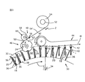
図3は、折り畳んだ新聞10内に添付物20を差し込むのに適したドラム形状の加工装置の一部を断面として示している。この種の加工装置は、例えばスイス特願第584153号および欧州特願第0341423号またはそれに対応する米国特許公報第3,951,399号並びに第4,981,291号に開示されている。加工装置の構造と機能についてはこれらの公報が参照される。
FIG. 3 shows a cross section of a part of a drum-shaped processing device suitable for inserting the
加工装置30はポケット状の収容部分32を有し、この収容部分は共通の回転軸34を中心に配置されて回転軸の方向に延びていると共に、半径方向外側が開放している。収容部分32は壁36によって、そして半径方向内側は底38によって区画されている。この加工装置30において前述の公報に記載された方法により新聞10と挿入される添付物20からなる最終製品が形成される。
The
図3には加工装置30の最後の部分のみが図示されており、その部分から移送装置44の把持部材42によって新聞10がその中に配置された添付物20と共に取り出されて、移送方向Wに移送される。加工装置30のこの部分には、回転方向Uに見て移送装置44の前段に、接着テープ部分24を取り付ける装置46が配置されている。この装置は接着テープ部分供給ユニット48と伝達輪50を有し、伝達輪は接着テープ部分供給ユニット48から供給された接着テープ部分24を、収容部分32内に配置され、かつその中へ移送された新聞10へ送ると共に、接着テープ部分24を新聞10に取り付けるように定められている。
FIG. 3 shows only the last part of the
接着テープ供給ユニット48は軸受シャフト52を有し、その軸受シャフトに接着テープストックロール54が軸承されており、接着テープロールから1対の移送ローラ56によって歩進的に接着テープ54’が引き出されて、その接着テープから回転駆動可能な切断ドラム60のカッター58によって接着テープ部分24が切断される。
The adhesive
特に図4から明らかなように、ほぼ円形の伝達輪50には周面に分配された凹部62が設けられており、この凹部の周方向に測定した中心距離は加工装置30の壁36の距離にほぼ相当する。伝達輪50は回転軸34に対して平行な回転軸64を中心に、周方向Uとは反対の矢印方向Vに回転駆動される。伝達輪50の周速度は壁36の周速度にほぼ相当し、かつ伝達輪50は、それぞれ新聞10の開放端縁22が凹部62内に来るように、加工装置30と同期化されており、これは特に図3に示されている。
As is clear from FIG. 4 in particular, the substantially
伝達輪50の外表面66のそれぞれ各凹部62の根の部分並びに凹部62間の円筒状の部分の、それぞれ矢印方向Vに見て各凹部62の先行の端部に隣接して吸引開口部68ないし68’が形成されている。吸引開口部68,68’は半径方向の吸引通路70を介して弁装置72と接続されており、それによって吸引開口部68,68’は図示しない負圧源と一時的に接続される。弁装置72には半径方向外側が開放した制御溝76を備えた制御ディスク74が設けられており、制御溝は周方向に所定の領域にわたって延びている。この制御溝76は制御導管78を介して負圧源と接続されると共に、伝達輪50が制御ディスク74を中心として回転する際に吸引通路70の内側端部が制御溝76の領域に来ると、それぞれ吸引通路70によって吸引開口部68,68’と接続される。
The suction opening 68 adjacent to the leading end of each
特に図4から明らかなように、接着テープ54’の一部が移送ローラの対56を越えて突出しており、その伝達輪50側の接着剤のついていない平坦な側が伝達輪の外表面66に接している。吸引開口部68が接着テープ54’のこの部分の領域に来ると、この吸引開口部58が弁装置72によって負圧源と接続され、同時に移送ローラの対56が送り方向Zに駆動される。それによって接着テープ54’の先行の端部領域が外表面66に接して保持されて、後続の部分が凹部62内へ挿入される。そのために移送ローラの対56の送り速度が伝達輪50の周速度よりも一時的に大きくなる。そして接着テープ54’を凹部62内に保持するために、吸引開口部68’も負圧源と接続される。同様に駆動される切断ドラム60によって接着テープ54’が切断され、それによって接着テープ部分24が分離される。その場合に2つの凹部62間の外表面66の部分がカッター58と共働する載置面として用いられる。従って回転する際に伝達輪50のそれぞれの凹部62が接着テープ部分24を支持し、その接着テープ部分の端部は凹部62を越えて延びている。
In particular, as is apparent from FIG. 4, a part of the
加工装置30と伝達輪50の回転の途中で、それぞれ新聞10の開放端縁22が凹部62内に挿入される。その場合に回転軸64と新聞10との距離は、接着テープ部分24の伝達輪50に関して半径方向外側の接着剤シートが新聞の開放端縁22の領域に接して、軽く押圧されるように調節される。吸引開口部68および68’に通気することによって接着テープ部分24が解放され、直ちに新聞10に貼り付く。加工装置30がさらに回転する途中で、移送装置44の把持部材42がそれぞれ上方から新聞10をその内部に配置された添付物20と共に上方から把持し、かつ把持部材の口が閉鎖する際に、開放端縁22を越えて突出している接着テープ部分24の端部領域24’を片18に押圧して、製品ユニットを固定して移送する。
During the rotation of the
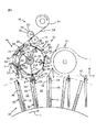
図5は伝達輪50についての他の可能な実施例を、図3と同様に図示するものである。伝達輪は回転軸64を中心に矢印V方向に回転駆動される支持ディスク80を有し、この支持ディスクには周方向に分配して伝達ピンチ82が配置されている。伝達ピンチ82のピンチ顎84の端部には吸引ヘッド86が設けられており、この吸引ヘッドも図4に関連して説明したのと同様に吸引通路70を介して弁装置72と接続されている。ピンチ顎84は、ばね部材88によって開放位置へ付勢されていると共に、ピンチレバー94に設けられた滑りシュー92と共働するリンク90により、支持ディスク80の回転位置に従って閉鎖位置へ移動することができる。
FIG. 5 illustrates another possible embodiment of the
開放された伝達ピンチ82の回転方向Vに見て先行の吸引ヘッド86が接着テープ部分供給ユニット48を通過すると、移送ローラの対56が作動されて、吸引ヘッド86が負圧源と接続される。この伝達ピンチ82の後続の吸引ヘッド86も接着テープ部分供給ユニット48を通過すると、吸引ヘッドが接着テープ54’を吸引して、本実施例においては切断工具としても形成されている移送ローラの対56が伝達ピンチ82に保持されている接着テープ部分24を接着テープ54’から切断する。さらに回転する途中で伝達ピンチ82は徐々に閉鎖されるが、これが矢印Sによって示されている。それによって接着テープ部分24はU字状に湾曲され、ピンチ顎84の移動路が開放端縁22の移動路を横切ると、新聞10の開放端縁を把持する。次に伝達ピンチ82は完全に閉鎖され、それによって接着テープ部分24を片18の外側26に押圧する。その後、該当する伝達ピンチ82の2つの吸引ヘッド86が通気されて、ピンチ顎84は再び開放位置へ移動する(矢印S’)。
When the preceding
ここでも新聞10はその中に配置されている添付物20と共に、既に説明した図3に示すように、加工装置30の収容部分32内に配置されている。ここでも形成された製品ユニットは移送装置44によって捕捉されて、さらに加工するために移送される。伝達ピンチ82と移送装置44の把持部材42が新聞10に接することができるように、加工装置30の壁36には凹部96が形成されている(図3も参照)。
Here again, the
図6に示す装置においては新聞10はその中に配置された添付物20と共に把持コンベヤ98によって垂直の懸架位置で移送される。その場合に把持コンベヤ98のクランプ100が新聞10を把持してそれを保持する。新聞10の上方にある折り目14は移送方向Fに対して直角に延びており、下方に位置する開放端縁22は下方から自由に接近することができる。
In the apparatus shown in FIG. 6, the
把持コンベヤ98の下方には、それぞれの接着テープ部分24を新聞10に取り付ける装置46が設けられており、接着テープ部分が開放端縁をつなぐ。この装置46は図5に示すものと全く同様な設計となっており、また、回転方向Vに駆動される支持ディスク80に配置されたピンチ顎84を備えている。ピンチ顎が接着テープ部分供給ユニット48からそれぞれ接着テープ部分24を引き取って、それを開放端縁22をつなぐように新聞10に当接させる。
Below the gripping
図7には図1および2と同様に、内部に配置された2つの添付物20を有する折り畳んだ新聞10が図示されている。添付物20と場合によっては新聞10の片18の所定領域に滑り止め手段102、例えば透明なシリコンシートが設けられている。その場合にそれぞれ少なくとも1つのこの種の領域が添付物20が相互に接触する接触面と、添付物20が新聞10の片18と接触する各接触面に設けられている。それによって添付物20は片18に関して、かつ相互に移動することを防止される。
FIG. 7 illustrates a folded
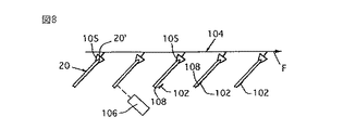
図8には滑り止め手段102を添付物20の外側に取り付ける装置が図示されている。添付物20は把持コンベヤ104によって個々に、水平の移送方向Fに関して斜め下方へ傾いた位置で移送され、その場合に把持部材105は添付物20の移送方向Fにおいて先行する折り目20’を保持する。把持コンベヤ104の下方にはスプレイ装置106が配置されており、このスプレイ装置はそばを通過する各添付物20の折り目20’から離れた所定の領域108に滑り止め手段102を塗布する。
FIG. 8 shows a device for attaching the anti-slip means 102 to the outside of the
図9に示す実施例においては、添付物20は同様に把持コンベヤ104によって移送方向Fに関して斜め下方に傾いた懸架位置で移送される。把持コンベヤ104の下方には配転駆動される支持ベルト110が配置されており、その上方の支持を行うベルトが把持コンベヤ104に対して平行に延びていると共に、把持コンベヤ104と同一の速度で駆動されている。支持ベルト110には把持手段から離れて保持カム112が設けられており、この保持カムは支持ベルト110と共に添付物20の開放端縁22の領域を捕捉するように定められている。支持ベルト110の下方の軸受シャフト52’にはストックスプール114が配置されており、このストックスプールから自己接着する滑り止めテープが2つの転向ローラ118を回って案内されて巻取りスプール120へ延びている。図10から明らかなように、滑り止めテープ116においてパーフォレーション122がラベル状のテープ部分124を区画している。2つの転向ローラ118間には、例えばシリンダピストンユニットによって駆動されるタペット126が配置されており、このタペットは滑り止めテープ116からパーフォレーションを切断してそれぞれ自己接着するテープ部分124を分離し、添付物20の下方に位置する平坦側に取り付ける。その場合に、保持カム112が押え手段として用いられる。完全を期するために、滑り止めテープ116は把持コンベヤ104のクロックによって駆動されているので、各添付物20についてそれぞれ1つのテープ部分124が供給されることに注意すべきである。
In the embodiment shown in FIG. 9, the
もちろん、図8または9と同様な装置を用いることによって添付物20の他方の側にも滑り止め手段102を設けることができる。
Of course, the anti-slip means 102 can be provided on the other side of the
滑り止め手段102を有する添付物20は、例えば図3に示すように、加工装置30へ供給される。そこで添付物20は新聞10内へ差し込まれる。このようにして形成された製品ユニットはその後に移送装置44によって移送される。
The
また、新聞10の2つの片18の多数の箇所を相互に結合することも考えられる。
It is also conceivable to connect a number of locations of the two
図示の実施例においては、添付物20は折り畳んだ新聞10の中央に配置されている。しかし、添付物20を新聞10の色々な部分の間に配置することもまた可能である。その場合には「片」という概念は、新聞10の添付物20の両側に配置された部分と考えることができる。
In the illustrated embodiment, the
また、新聞10の代わりに他の種類の印刷物、例えば雑誌を使用することも可能である。
It is also possible to use other types of printed matter, such as magazines, instead of the
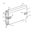
図11には製品ユニットが図示されており、この製品ユニットにおいては図1に示す製品ユニットの場合と同様に、折り目14に沿って折り畳んだ新聞または雑誌10の片18間に3つの添付物20が配置されている。図1に示す実施例とは異なり、新聞10の回りに開放端縁22が同様に開放したカバー128が当てられている。カバー128は開放端縁22の領域で接着テープ部分24によって纏められており、接着テープ部分の端部領域24’がカバー128の外側130に付着している。この接着テープ部分24の他に製品ユニットの側端縁29の領域には、図11に破線で示され、かつ図1および2を用いて既に説明したように他の接着テープ部分224が取り付けられている。
FIG. 11 shows a product unit in which three
図12に示す製品ユニットにおいては、端縁214に沿って折り畳んだ、相互に隣り合う2つの印刷物132,134がジャケット136によって包囲されている。その場合にジャケット136の一方の側部分138は印刷物132,134の開放端縁222を、ジャケット136の他方の側部分138’に固定された閉鎖フラップ140によって覆っている。製品ユニットの開放側142には図1および2に示す実施例の場合と同様に接着テープ部分224が設けられており、この接着テープ部分の端部領域224’がジャケット136の側部分138,138’の外側に付着している。接着テープ部分224は印刷物132,134が側方に滑り落ちるのを防止する。
In the product unit shown in FIG. 12, two
印刷物132,134は新聞、雑誌またはそれらの一部、例えば添付物とすることができる。
The printed
カバー128とジャケット136は、まず、印刷物10,20,132,134のパックまたは束をまとめて保護するために用いられると共に、例えば紙またはプラスチックから形成される。
The
また、図11および12に示す製品ユニットにおいて、接着テープ部分24,224の代わりに、またはそれに加えて、図7ないし10を参照して説明したように、印刷物10,20,132,134の外側に滑り止めを施設けることも考えられる。
In addition, in the product unit shown in FIGS. 11 and 12, instead of or in addition to the
さらに、図11に示す製品ユニットにおいて、個々の印刷物10,20を図12に図示したものと同様に相互に並べて配置することも可能であることを指摘しておきたい。同様に図12に示す製品ユニットにおいて、図11に示すのと同様に印刷物132,134を相互に入り組ませることも可能である。
Furthermore, it should be pointed out that in the product unit shown in FIG. 11, the individual printed
10 新聞(印刷物ユニット)
14 折り目
18 片
20 添付物(雑誌、パンフレット、定期刊行物等)
22 開放端縁
24 接着(粘着)テープ部分
24’ 端部領域
26 片の外側
28 オーバーフォールドの部分
29 側端縁
30 加工装置
32 収容部分
44 移送装置
46 接着テープ部分を取り付ける装置
48 接着テープ部分供給ユニット
50 伝達輪
70 吸引通路
72 弁装置
82 伝達ピンチ
84 ピンチ顎
98 把持コンベヤ
100 クランプ
102 滑り止め手段
104 把持コンベヤ
106 スプレイ装置
116 滑り止めテープ
124 テープ部分
128 カバー
130 カバーの外側
132,134 印刷物
136 ジャケット
138,138’ ジャケットの側部分
140 閉鎖フラップ
142 製品ユニットの開放側
222 印刷物の開放端縁
224 側方接着テープ部分
224’ 側方接着テープ部分の端部領域
10 Newspaper (printed product unit)
14
22
Claims (9)
内側を有する片(18,138,138’)と、折り目(14)及び開放端縁(22)とが形成され、かつ該開放端縁(22)が該折り目(14)の反対側に位置するように折られている外側部分(10,128,136)を供給する段階と、
外側を有する各々の印刷物(20,132,134)を供給する段階と、
該外側部分(10,128,136)の片(18,138,138’)の間に該印刷物(20,132,134)を配置する段階と、及び
該外側部分(10,128,136)の該片(18,138,138’)の内側と、該片の間に置かれた該印刷物(20,132,134)との間で分離可能な結合をもたらすために、該外側部分(10,128,136)の該片(18,138,138’)の1つの内側に面している該印刷物(20,132,134)の各外側上の所定の領域(108)内、かつ/または該外側部分(10,128,136)の該片(18,138,138’)の該内側上の該所定の領域(108)内に結合手段(102,124)を適用し、かつ該外側部分(10,128,136)の該片(18,138,138’)が、該片の間に置かれた該印刷物(20,132,134)を介して間接的に分離可能に結合するように、該開放端縁(22)であって該外側部分(10,128,136)の該折れ目(14)から遠く離れている該所定の領域(108)内で結合手段(102,124)によって互いに該印刷物(20,132,134)を分離可能に結合する段階と、
を備えているところのいくつかの部分からなる製品ユニットを形成する方法。 A method for forming a product unit consisting of several parts comprises the following steps:
A piece (18, 138, 138 ′) having an inner side, a fold (14) and an open edge (22) are formed, and the open edge (22) is located on the opposite side of the fold (14). Supplying outer portions (10, 128, 136) that are folded like
Providing each print (20, 132, 134) having an outer side;
Placing the print (20, 132, 134) between pieces (18, 138, 138 ′) of the outer portion (10, 128, 136); and
Separable coupling between the inside of the piece (18, 138, 138 ') of the outer part (10, 128, 136) and the printed matter (20, 132, 134) placed between the pieces Pre-determined on each outer side of the print (20, 132, 134) facing inward of one of the pieces (18, 138, 138 ′) of the outer part (10, 128, 136). Coupling means (102, 108) and / or within the predetermined region (108) on the inside of the piece (18, 138, 138 ′) of the outer portion (10, 128, 136). 124) and the pieces (18, 138, 138 ′) of the outer part (10, 128, 136) are passed through the printed matter (20, 132, 134) placed between the pieces. The open edge (22) so as to be indirectly separable The prints (20, 132, 134) are separated from each other by a coupling means (102, 124) within the predetermined region (108) remote from the fold (14) of the side portion (10, 128, 136). A possible coupling stage;
A method of forming a product unit consisting of several parts of the place and a.
移送装置(104)と、塗布装置(106,126)と、加工手段(30)及び搬出コンベア(44)とによって特徴づけられており、
該移送装置(104)は、該塗布装置(106,126)を通過した該印刷物(20,132,134)を個々に移送するようになっていて、
該加工手段(30)は、該移送装置(104)から解放され、該外側部分(10,128,136)と一緒に結合手段(102,124)が設けられている該印刷物(20,132,134)を運ぶようになっており、
該塗布装置(106,116)は、該外側部分(10,128,136)の該片(18,138,138’)の内側と、該片の間に置かれた該印刷物(20,132,134)との間を分離可能に結合させるために、該外側部分(10,128,136)の該片(18,138,138’)の1つの内側に面している該印刷物(20,132,134)の各外側上の所定の領域(108)に結合手段(102,124)を付与するようになっていて、かつ該外側部分と該印刷物とを互いに分離可能に結合するために、該開放端縁(22)であって該外側部分(10,128,138)の該折り目(14)が離れている、該印刷物(20,132,134)上の該所定の領域(108)に結合手段(102,124)を付与するようになっており、かつ
該搬出コンベア(44)が、該加工手段(30)から離れた、いくつかの部分からなる製品ユニットを移送し、かつ該所定の領域(108)で該外側部分(10,128,136)の該片(18,138,138’)を相互に押し付けるようになっていることを特徴とするいくつかの部分からなる製品ユニットを形成する装置。 The outer part (10, 128) folded to form a piece (18, 138, 138 ') having an inner side and a fold (14) and an open end (22) opposite the fold (14). 136) and a print (20, 132, 134) disposed between the pieces (18, 138, 138 ′) of the outer part (10, 128, 136). An apparatus for forming a product unit comprising:
Characterized by a transfer device (104), a coating device (106, 126), a processing means (30) and a carry-out conveyor (44);
The transfer device (104) is configured to individually transfer the printed matter (20, 132, 134) that has passed through the coating device (106, 126).
The processing means (30) is released from the transfer device (104) and the printed matter (20, 132,) provided with coupling means (102, 124) together with the outer part (10, 128, 136). 134)
The applicator (106, 116) is arranged on the inside of the piece (18, 138, 138 ′) of the outer part (10, 128, 136) and the printed matter (20, 132, 136) placed between the pieces. 134) and the print (20, 132) facing the inside of one of the pieces (18, 138, 138 ′) of the outer portion (10, 128, 136). , 134) is provided with a coupling means (102, 124) in a predetermined area (108) on each outer side of the outer side and in order to detachably couple the outer part and the printed matter to each other. Bonded to the predetermined region (108) on the printed product (20, 132, 134), which is the open edge (22) and the fold (14) of the outer portion (10, 128, 138) is separated Means (102, 124) And
The unloading conveyor (44) transports several parts of the product unit away from the processing means (30) and in the predetermined area (108) of the outer part (10, 128, 136). An apparatus for forming a product unit consisting of several parts, characterized in that the pieces (18, 138, 138 ') are pressed against each other .
折り畳んだ外側部分(10,128,136)と印刷物(20,132,134)を備えており、
該折り畳んだ外側部分は、片(18,138,138’);折り目(14)及び開放端縁(22)が形成されるように折り畳まれていて、該開放端縁(22)は該折り目(14)の反対側に位置しており、また
該印刷物(20,132,134)が、該外側部分(10,128,136)の該片(18,138,138’)の間に配置されているものにおいて、
該外側部分(10,128,136)の該片(18,138,138’)が、それらの間に置かれた該印刷物(20,132,134)を介して間接的に互いに分離可能に結合されていて、この分離可能の結合が、所定の領域(108)内で該外側部分(10,128,136)の該片(18,138,138’)と該印刷物(20,132,134)との間、及び該所定の領域(108)内での該印刷物(20,132,134)の間に置かれる結合手段(102,124)によって行われており、該所定の領域(108)が該開放端縁(22)で該外側部分(10,128,136)の該折り目(14)から遠く離れていることを特徴とする、いくつかの部品からなる製品ユニット。 A product unit consisting of several parts, formed by the method according to claim 1, wherein the product unit consisting of several parts is
It has a folded outer part (10, 128, 136) and printed matter (20, 132, 134),
The folded outer portion is folded to form a piece (18, 138, 138 ′); a fold (14) and an open edge (22), the open edge (22) being the fold ( 14) on the opposite side of
In the printed matter (20, 132, 134) disposed between the pieces (18, 138, 138 ′) of the outer portion (10, 128, 136),
The pieces (18, 138, 138 ′) of the outer part (10, 128, 136) are indirectly separable from each other via the printed matter (20, 132, 134) placed between them. This separable connection is made within the predetermined area (108) by the strip (18, 138, 138 ') of the outer portion (10, 128, 136) and the printed product (20, 132, 134). And by means of coupling (102, 124) placed between the printed matter (20, 132, 134) in the predetermined area (108), the predetermined area (108) Product unit consisting of several parts, characterized in that the open edge (22) is remote from the fold (14) of the outer part (10, 128, 136) .
Applications Claiming Priority (1)
| Application Number | Priority Date | Filing Date | Title |
|---|---|---|---|
| CH32194 | 1994-02-04 |
Related Parent Applications (1)
| Application Number | Title | Priority Date | Filing Date |
|---|---|---|---|
| JP7015773A Division JPH07285515A (en) | 1994-02-04 | 1995-02-02 | Method and device to form print unit consisting of several parts |
Related Child Applications (1)
| Application Number | Title | Priority Date | Filing Date |
|---|---|---|---|
| JP2006140632A Division JP2006298496A (en) | 1994-02-04 | 2006-05-19 | Device for forming printed product unit comprising several sections |
Publications (2)
| Publication Number | Publication Date |
|---|---|
| JP2004345741A JP2004345741A (en) | 2004-12-09 |
| JP3857701B2 true JP3857701B2 (en) | 2006-12-13 |
Family
ID=4184360
Family Applications (3)
| Application Number | Title | Priority Date | Filing Date |
|---|---|---|---|
| JP7015773A Withdrawn JPH07285515A (en) | 1994-02-04 | 1995-02-02 | Method and device to form print unit consisting of several parts |
| JP2004211656A Expired - Lifetime JP3857701B2 (en) | 1994-02-04 | 2004-07-20 | Method and apparatus for forming a multi-part printed product unit |
| JP2006140632A Pending JP2006298496A (en) | 1994-02-04 | 2006-05-19 | Device for forming printed product unit comprising several sections |
Family Applications Before (1)
| Application Number | Title | Priority Date | Filing Date |
|---|---|---|---|
| JP7015773A Withdrawn JPH07285515A (en) | 1994-02-04 | 1995-02-02 | Method and device to form print unit consisting of several parts |
Family Applications After (1)
| Application Number | Title | Priority Date | Filing Date |
|---|---|---|---|
| JP2006140632A Pending JP2006298496A (en) | 1994-02-04 | 2006-05-19 | Device for forming printed product unit comprising several sections |
Country Status (7)
| Country | Link |
|---|---|
| US (1) | US5632476A (en) |
| EP (1) | EP0666186B1 (en) |
| JP (3) | JPH07285515A (en) |
| AT (1) | ATE170465T1 (en) |
| CA (1) | CA2141639C (en) |
| DE (1) | DE59406831D1 (en) |
| ES (1) | ES2119953T3 (en) |
Families Citing this family (21)
| Publication number | Priority date | Publication date | Assignee | Title |
|---|---|---|---|---|
| IT1301916B1 (en) * | 1998-08-10 | 2000-07-07 | Gianattilio Meratti | METHOD FOR PACKAGING BOOKS STARTING FROM A STACKING OF THE SEGNATURETRA THEIR SEWS. |
| FR2785568B1 (en) * | 1998-11-06 | 2000-12-15 | Hachette Livre | BOOKSHOP AND / OR STATIONERY ARTICLE SUCH AS, IN PARTICULAR, BOOK, NOTEBOOK, BROCHURE OR THE LIKE, DESTINED TO BE POSTAL WITHOUT ENVELOPE |
| DK1112861T3 (en) * | 1999-12-28 | 2004-02-23 | Ferag Ag | Method and apparatus for connecting supplementary products with printing products |
| ATE276959T1 (en) | 2001-07-10 | 2004-10-15 | Ferag Ag | DEVICE FOR ATTACHING SUPPLEMENTARY PRODUCTS TO PRINTED PRODUCTS |
| EP1281650B1 (en) * | 2001-07-30 | 2005-08-17 | Ferag AG | Method and device for grouping and further transporting flat articles |
| EP1516839B1 (en) * | 2003-09-18 | 2007-03-21 | Ferag AG | Device and method for attaching supplements to printed products |
| ATE394332T1 (en) * | 2003-12-22 | 2008-05-15 | Ferag Ag | METHOD AND DEVICE FOR STABILIZING AND POSITIONING FLAT OBJECTS |
| CA2622931A1 (en) * | 2005-09-19 | 2007-03-29 | Ferag Ag | Covering sheet for a printed product and method for packaging newspapers or magazines by means of said covering sheet |
| US7611135B2 (en) * | 2005-12-05 | 2009-11-03 | Goss International Americas, Inc. | Inserter with closure device |
| US8608149B2 (en) * | 2007-10-26 | 2013-12-17 | Goss International Americas, Inc. | Sectioned tabloid printing press and method |
| CH705651B1 (en) * | 2007-12-07 | 2013-04-30 | Ferag Ag | A method of sealing a flat product, and device for carrying out the method. |
| WO2010033588A1 (en) * | 2008-09-16 | 2010-03-25 | Goss International Americas, Inc | Offset folded newspaper stabilization method and product |
| ATE530481T1 (en) * | 2009-04-23 | 2011-11-15 | Mueller Martini Holding Ag | METHOD FOR TURNING PRINTED PRODUCTS TRANSPORTED ON A CONVEYOR IN A CONVEYOR STREAM |
| US8474503B2 (en) | 2010-09-09 | 2013-07-02 | Kirk-Rudy, Inc. | Systems and methods for sealing the trailing edge of a printed article |
| EP2655078B1 (en) | 2010-12-20 | 2016-11-23 | Ferag AG | Method for applying at least one embracing element to a flat product composition, and embracing element applying device for carrying out the method |
| CH704243A1 (en) | 2010-12-20 | 2012-06-29 | Ferag Ag | Stack or collection of essentially flat intermediate products as well as methods for producing such a stack or such a collection. |
| CH704241A1 (en) | 2010-12-20 | 2012-06-29 | Ferag Ag | A method for assembling a stack or a collection of loosely-single- or multilayer precursors, an assortment of precursors and an applicator for preparing such compositions. |
| ITMI20110275U1 (en) * | 2011-08-10 | 2013-02-11 | Sitma Machinery S P A | PRESS RELEASE, A NEWSPAPER, A NEWSPAPER, A MAGAZINE OR A PERIODIC, CONTAINING REMOVABLE INSERTS |
| CH705360A1 (en) * | 2011-08-15 | 2013-02-15 | Ferag Ag | Method and device for collecting flat objects. |
| US20180170091A1 (en) * | 2016-12-21 | 2018-06-21 | Kabushiki Kaisha Toshiba | Sheet processing device and sheet processing method field |
| CH717452A1 (en) * | 2020-05-25 | 2021-11-30 | Ferag Ag | Device and method for applying a flat application element to the outside of a conveyor unit. |
Family Cites Families (17)
| Publication number | Priority date | Publication date | Assignee | Title |
|---|---|---|---|---|
| CH540816A (en) * | 1972-05-08 | 1973-08-31 | Grapha Holding Ag | Method of packaging a brochure or magazine |
| CH584153A5 (en) * | 1973-10-10 | 1977-01-31 | Ferag Ag | |
| US4004962A (en) * | 1975-06-09 | 1977-01-25 | Pitney-Bowes, Inc. | Sealing machine |
| US4160687A (en) * | 1978-06-26 | 1979-07-10 | Avery International Corporation | Magazine page labeling apparatus |
| SE426754B (en) * | 1979-05-22 | 1983-02-07 | Torsten Ivefjell | CLOSING DEVICE FOR Journals and Similar, INTENDED TO BE USED FOR DISTRIBUTION AND SALES HALLING |
| DE3006322A1 (en) * | 1980-02-20 | 1981-08-27 | Focke & Co, 2810 Verden | DEVICE FOR APPLYING BANDEROLS TO SQUARE CIGARETTE PACKS |
| US4647333A (en) * | 1984-10-02 | 1987-03-03 | New Jersey Machine Inc. | Combination labeling and literature applying machine |
| DE58900823D1 (en) * | 1988-05-11 | 1992-03-26 | Ferag Ag | FACILITIES FOR GATHERING, INSERTING AND COLLECTING PRINT PRODUCTS. |
| SE464757B (en) * | 1989-10-06 | 1991-06-10 | Wamac Ab | PROCEDURE AND DEVICE FOR PAGE OF ANNEXES IN MAGAZINES |
| US5096176A (en) * | 1990-12-24 | 1992-03-17 | Pitney Bowes Inc. | Sheet set separation using folded strips |
| US5159798A (en) * | 1991-08-29 | 1992-11-03 | Stepper, Inc. | Method and apparatus for taping closed the open edge of an assembled newspaper having loose contents |
| US5188349A (en) * | 1991-10-07 | 1993-02-23 | Ferag Ag | Method and apparatus for inserting printed products in a folded main product |
| IT1253216B (en) * | 1991-10-21 | 1995-07-11 | Gd Spa | DEVICE FOR THE APPLICATION OF ADHESIVE BANDS TO PACKAGES |
| DE69214614T2 (en) * | 1991-12-16 | 1997-03-20 | Xerox Corp | Removable holding system for sets of copy sheets |
| DE4220791A1 (en) * | 1992-06-25 | 1994-01-05 | Roland Man Druckmasch | Gluing mechanism using double-sided adhesive tape - has parting knife cutting through tape from side to be glued to material. |
| DE4220792C2 (en) * | 1992-06-25 | 1995-10-05 | Roland Man Druckmasch | Gluing device |
| US5468325A (en) * | 1992-10-26 | 1995-11-21 | Windmoller & Holscher | Process for applying an adhesive band having one adhesive side |
-
1994
- 1994-12-15 DE DE59406831T patent/DE59406831D1/en not_active Expired - Lifetime
- 1994-12-15 EP EP94119800A patent/EP0666186B1/en not_active Expired - Lifetime
- 1994-12-15 ES ES94119800T patent/ES2119953T3/en not_active Expired - Lifetime
- 1994-12-15 AT AT94119800T patent/ATE170465T1/en active
-
1995
- 1995-01-27 US US08/378,980 patent/US5632476A/en not_active Expired - Lifetime
- 1995-02-01 CA CA002141639A patent/CA2141639C/en not_active Expired - Fee Related
- 1995-02-02 JP JP7015773A patent/JPH07285515A/en not_active Withdrawn
-
2004
- 2004-07-20 JP JP2004211656A patent/JP3857701B2/en not_active Expired - Lifetime
-
2006
- 2006-05-19 JP JP2006140632A patent/JP2006298496A/en active Pending
Also Published As
| Publication number | Publication date |
|---|---|
| EP0666186A1 (en) | 1995-08-09 |
| DE59406831D1 (en) | 1998-10-08 |
| JP2006298496A (en) | 2006-11-02 |
| CA2141639A1 (en) | 1995-08-05 |
| ATE170465T1 (en) | 1998-09-15 |
| JPH07285515A (en) | 1995-10-31 |
| JP2004345741A (en) | 2004-12-09 |
| ES2119953T3 (en) | 1998-10-16 |
| US5632476A (en) | 1997-05-27 |
| CA2141639C (en) | 2007-04-10 |
| EP0666186B1 (en) | 1998-09-02 |
Similar Documents
| Publication | Publication Date | Title |
|---|---|---|
| JP3857701B2 (en) | Method and apparatus for forming a multi-part printed product unit | |
| JP2567562B2 (en) | Non-peeling paper label processing apparatus and processing method thereof | |
| US9650177B2 (en) | Linerless packing and shipping label system | |
| JPH11505495A (en) | How to attach labels to containers | |
| JPH10503455A (en) | Adhesive tape application device | |
| JPH09506053A (en) | Linerless label printer and transport system | |
| WO2005091950A3 (en) | Transfer tape and method for cutting and spooling a paper web | |
| AU705398B2 (en) | Apparatus for printing labels and a self-releasing print roller therefor | |
| MX2010008203A (en) | Method and apparatus for applying pressure sensitive adhesive labels to containers. | |
| US20060185798A1 (en) | Flexible laminae handling apparatus | |
| AU2003205538B2 (en) | A device for dispensing two sided adhesive tape pieces and a refill roll for the device | |
| JP3067413B2 (en) | Roll Labeler | |
| JPS62142677A (en) | Paper-discharging device for rotary stencil duplicator | |
| JPH11505480A (en) | Working with printing blankets | |
| JP3365795B2 (en) | Apparatus for attaching web sections or labels to goods | |
| JP5223158B2 (en) | Coupon positioning and rotating wheel | |
| JP4493764B2 (en) | Labeling machine | |
| JPH07121735B2 (en) | Label transfer and sticking device | |
| JPS5831786A (en) | Transfer type heat-sensitive recorder | |
| JP4493768B2 (en) | Label transfer device and label transfer method for label sticking machine | |
| JP2542277B2 (en) | Label sticking method and device | |
| JP3860464B2 (en) | Label automatic peeling device | |
| JP3685519B2 (en) | Pasting device | |
| JPS5974042A (en) | Device for removing defective label of labeller | |
| JPH0223418B2 (en) |
Legal Events
| Date | Code | Title | Description |
|---|---|---|---|
| A977 | Report on retrieval |
Free format text: JAPANESE INTERMEDIATE CODE: A971007 Effective date: 20051114 |
|
| A131 | Notification of reasons for refusal |
Free format text: JAPANESE INTERMEDIATE CODE: A131 Effective date: 20051122 |
|
| A601 | Written request for extension of time |
Free format text: JAPANESE INTERMEDIATE CODE: A601 Effective date: 20060221 |
|
| A602 | Written permission of extension of time |
Free format text: JAPANESE INTERMEDIATE CODE: A602 Effective date: 20060224 |
|
| A521 | Request for written amendment filed |
Free format text: JAPANESE INTERMEDIATE CODE: A523 Effective date: 20060519 |
|
| TRDD | Decision of grant or rejection written | ||
| A01 | Written decision to grant a patent or to grant a registration (utility model) |
Free format text: JAPANESE INTERMEDIATE CODE: A01 Effective date: 20060815 |
|
| A61 | First payment of annual fees (during grant procedure) |
Free format text: JAPANESE INTERMEDIATE CODE: A61 Effective date: 20060914 |
|
| R150 | Certificate of patent or registration of utility model |
Free format text: JAPANESE INTERMEDIATE CODE: R150 |
|
| FPAY | Renewal fee payment (event date is renewal date of database) |
Free format text: PAYMENT UNTIL: 20100922 Year of fee payment: 4 |
|
| FPAY | Renewal fee payment (event date is renewal date of database) |
Free format text: PAYMENT UNTIL: 20110922 Year of fee payment: 5 |
|
| FPAY | Renewal fee payment (event date is renewal date of database) |
Free format text: PAYMENT UNTIL: 20120922 Year of fee payment: 6 |