JP3854633B2 - Turbocharger for internal combustion engine - Google Patents
Turbocharger for internal combustion engine Download PDFInfo
- Publication number
- JP3854633B2 JP3854633B2 JP51369495A JP51369495A JP3854633B2 JP 3854633 B2 JP3854633 B2 JP 3854633B2 JP 51369495 A JP51369495 A JP 51369495A JP 51369495 A JP51369495 A JP 51369495A JP 3854633 B2 JP3854633 B2 JP 3854633B2
- Authority
- JP
- Japan
- Prior art keywords
- turbocharger
- motor
- control device
- gas flow
- flow control
- Prior art date
- Legal status (The legal status is an assumption and is not a legal conclusion. Google has not performed a legal analysis and makes no representation as to the accuracy of the status listed.)
- Expired - Lifetime
Links
Images


Classifications
-
- F—MECHANICAL ENGINEERING; LIGHTING; HEATING; WEAPONS; BLASTING
- F02—COMBUSTION ENGINES; HOT-GAS OR COMBUSTION-PRODUCT ENGINE PLANTS
- F02B—INTERNAL-COMBUSTION PISTON ENGINES; COMBUSTION ENGINES IN GENERAL
- F02B37/00—Engines characterised by provision of pumps driven at least for part of the time by exhaust
- F02B37/12—Control of the pumps
- F02B37/18—Control of the pumps by bypassing exhaust from the inlet to the outlet of turbine or to the atmosphere
- F02B37/183—Arrangements of bypass valves or actuators therefor
-
- F—MECHANICAL ENGINEERING; LIGHTING; HEATING; WEAPONS; BLASTING
- F02—COMBUSTION ENGINES; HOT-GAS OR COMBUSTION-PRODUCT ENGINE PLANTS
- F02B—INTERNAL-COMBUSTION PISTON ENGINES; COMBUSTION ENGINES IN GENERAL
- F02B37/00—Engines characterised by provision of pumps driven at least for part of the time by exhaust
- F02B37/12—Control of the pumps
- F02B37/18—Control of the pumps by bypassing exhaust from the inlet to the outlet of turbine or to the atmosphere
- F02B37/183—Arrangements of bypass valves or actuators therefor
- F02B37/186—Arrangements of actuators or linkage for bypass valves
-
- Y—GENERAL TAGGING OF NEW TECHNOLOGICAL DEVELOPMENTS; GENERAL TAGGING OF CROSS-SECTIONAL TECHNOLOGIES SPANNING OVER SEVERAL SECTIONS OF THE IPC; TECHNICAL SUBJECTS COVERED BY FORMER USPC CROSS-REFERENCE ART COLLECTIONS [XRACs] AND DIGESTS
- Y02—TECHNOLOGIES OR APPLICATIONS FOR MITIGATION OR ADAPTATION AGAINST CLIMATE CHANGE
- Y02T—CLIMATE CHANGE MITIGATION TECHNOLOGIES RELATED TO TRANSPORTATION
- Y02T10/00—Road transport of goods or passengers
- Y02T10/10—Internal combustion engine [ICE] based vehicles
- Y02T10/12—Improving ICE efficiencies
Abstract
Description
この発明は内燃機関用ターボチャージャに関するものであり、さらに特にターボチャージャの排気ガス駆動タービンの制御に関するものである。
特に乗用車や商業用軽量車両における圧縮点火機関の人気の増大に伴って、そのようなエンジンが出力を高めるために小さいターボチャージャを提供する動機が存在する。うまく設計されたターボチャージャを付ければ、圧縮点火機関はより大きな容量のエンジンに類似する出力を発生することができる。さらに、環境浄化や燃料消費量がガソリン・エンジンに比べて改善されることそえあり得る。またその一方で、ガソリン・エンジンに使用されるターボチャージャはその出力を非常に増大させることができる。
典型的な排気ガス駆動ターボチャージャは、回転軸を支える軸受ハウジング組立品を含んでおり、その回転軸の一端は圧縮機ハウジングによって囲まれた空気圧縮機ホイールを支え、他端はターボチャージャに囲まれたタービン・ホイールを支え、そしてその回転軸は圧縮機を駆動すべき排気ガス流れにさらされている。そのようなターボチャージャがエンジンの空気導入マニホールドにおいて発生させ得るブースト圧力を抑制するために、制御可能な排気ガス・バイパス弁を含むいわゆる「ウェーストゲート」を設けることが提案されてきた。典型的には、そのようなウェーストゲート弁は、弁開方向に、ターボチャージャ圧縮機の出力から引き出された制御圧力に対する圧力応答ダイアフラム主体に接続された弁軸を有するばねで片寄せられたポペット弁で構成されてきた。そのようなウェーストゲート弁を提供することによって、ターボチャージャの過剰ブーストを防止し、そして有利にターボチャージャの操作をエンジンの要求にマッチさせることを改良することが可能である。しかしながら、そのシステムは空気操作式であり、ブースト圧力のみならず、ばね片寄せの弁、有効制御面積及び弁に作用する排気ガス圧力に依存している。実際には、そのような制御は、過剰ブーストによるエンジンへの可能な損傷を防止する一方で、適度なエンジン性能を与えることに合致する妥協に過ぎない。
ターボチャージャ制御についてはまた、ターボチャージャの駆動タービンの入力ノズル形状が可変であるという代案が提供されている。そのような可変入力ノズルの一形式は1993年11月24日に広告された欧州特許EP−A−0571205において述べられており、その開示は参照の方法で組み込まれている。そのような提案において、ターボチャージャのタービン・ハウジングはエンジンからの排気ガスを受けるための入力ノズルを有し、タービン・ホイールの羽根の上流端に衝突すべきそのようなガスを案内する形状に作られている。そのノズルはタービン・ホイールの前記上流端の回りに伸びる、軸方向に間隔を有する側壁を有し、軸方向に伸びた一定間隔の、そして傾斜した羽根が側壁と側壁の間に仕切られた空間を横切り、一側壁によって支えられ、そして他側壁の溝の中に受け入れられることができるようになっている。一側壁はタービン・ホイールのハウジング下流の穴の中に滑動可能に支えられている軸方向移動可能なスリーブの一端によって形成され、そして、そのスリーブを動かしてターボチャージャ圧縮機の出力から引き出された空気圧力に応答して前記ノズルの形状を変化させる手段が与えられている。再び、ウェーストゲート式ターボチャージャの場合のように、可変ノズル形状の空気圧制御は不変及び可変のパラメータに依存し、これらはエンジンの全運転条件に対する理想値より小さくてよい。
本発明の目的はそれぞれの内燃機関の要求によりよく順応する改良された制御機構を備えた内燃機構用ターボチャージャを提供することである。
本発明の一局面に従えば、ハウジング内の軸受装置に支持された駆動軸を含むターボチャージャが提供され、その駆動軸は排気ガス駆動タービン・ホイールを圧縮機のインペラに駆動的に接続し、ガス流制御装置がそのタービン・ホィールの上流側に設けられてターボチャージャの操作性能を調整するために操作可能であり、そしてまた、そのターボチャージャには、少なくとも圧縮機の吐出圧力に依存する電気信号に応答して連結装置を介してガス流制御装置の操作を調整するための電気的駆動可能なアクチュエータ・モータが含まれ、その連結装置は雄ねじ付きリード・スクリューとそれに対応して噛み合う雌ねじスクリュー部材から成っている。
好ましい配列においては、雌ねじスクリュー部材と雄ねじリード・スクリューのうちの一方は、連結装置の長手方向の範囲を変えるために、アクチュエータ・モータによって駆動される時、前記スクリュー部材と前記リード・スクリューのうちの他方の回転運動に対して一般に直線的に運動するように配列されている。好ましくは、リード・スクリューがアクチュエータ・モータの駆動によって回転し、スクリュー部材は一般に直線的に運動する。リード・スクリューはマルチスタートねじを備えていると有利となる。
本発明の別の局面に従えば、ハウジング内の軸受装置に支持された駆動軸を含む提案されたターボチャージャにおいて、その駆動軸は排気ガス駆動タービン・ホイールを圧縮機のインペラに駆動的に接続し、ガス流制御装置がそのタービン・ホイールの上流側に設けられてターボチャージャの操作性能を調整するために操作可能であり、そしてまた、そのターボチャージャには、少なくとも圧縮機の吐出圧力に依存する電気信号に応答して連結装置を介してガス流制御装置の操作を調整するための電気的駆動可能なアクチュエータ・モータが含まれ、その連結装置は固定長さの連結材から成り、モータ出力クランク・アームがその連結材に回転可能に接続され、別のクランク・アームが前記モータ出力クランク・アームと異なる位置においてその連結材に回転可能に接続されている。
初期の調節に備えて、固定長さの連結材の長さは調整可能とすることができる。好ましい配列においては、2個のクランク・アームは一般に互いに平行に設けられている。
本発明の両局面において、ガス流制御装置はタービン・ホイールの上流からのタービン・ホイール排気ガスの回りのバイパスへ操作可能なウェーストゲート弁を含むことができる。ガス流制御装置はまた、タービン・ホイールへの排気ガス入力において可変形状のノズルとすることができる。
本発明がより明確に理解され、容易に実施に移すことができるように、下記の添付図面を参照して、例示の方法で、より詳細に述べる。
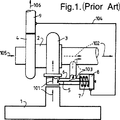
第1図はウェーストゲート式ターボチャージャの典型的な既知の形状を部分断面で示した概念図である。
第2a図及び第2b図は、それぞれ本発明によるターボチャージャのウェーストゲート弁と作動機構の一実施例を線図的に示した平面図及び側面図である。
第3a図、第3b図及び第3c図は、それぞれ本発明によるターボチャージャの実用的実施例を示した側面図、正面図及び背面図であり、この場合、ガス流制御装置はウェーストゲート弁である。
第4図は、本発明によるターボチャージャの別の実用的実施例を示した側面図であり、この場合、ガス流制御装置はウェーストゲート弁である。
第5図は、本発明によるターボチャージャの実施例を線図で示したもので、ガス流制御装置用制御手段を含んでいる。
第6図は、本発明によるターボチャージャを取り付けたエンジンについて行ったテストにより応答マップであり、この場合、リード・スクリュー連結装置を有するアクチュエータ・モータがウェーストゲート弁の位置を制御するために使用された。
第7図は、本発明による可変形状タービン入口ノズル式ターボチャージャの一実施例を示す断面図である。
第1図を見れば、既知のウェーストゲート式ターボチャージャは内燃機関の排気マニホールド1に接続されているように図示されている。ターボチャージャは軸受ハウジング2を含んでおり、軸受ハウジング2の内側では、軸(図示せず)が一端においてタービン・ケーシング3内でタービン・ホイールを支え、他端において圧縮機ケーシング4内で空気圧縮機インペラを支えている。ケーシング3内外への排気ガスの流入及び流出は矢印101及び102で示され、ウェーストゲート弁5が側流またはバイパス通路6の中に設けられている。ウェーストゲート弁5が開いた時、矢印103で示されたガスは、タービン・ケーシング3内を通過することなく、弁5及び通路6を経由して車両の主排気管へ流れることができる。ウェーストゲート弁5は、圧力応答アクチュエータ8を有する空気圧式アクチュエータのばね7により弁開時には片寄せられ、アクチュエータ8は弁開時にはターボチャージャ圧縮機ケーシング4の空気出口に直接接続されているエンジン空気入口9内に存在する吐出圧力にさらされている。圧縮機ケーシング4の流入及び流出はそれぞれ矢印105及び106で示されている。序文で述べたように、ウェーストゲート弁付きの第1図に示すターボチャージャは構造上かなり簡単である一方で操作条件の幅広い範囲に関連した欠点を有する。
第2a図及び第2b図を見れば、示された一般的配置において、ガス流制御装置はウェーストゲート弁の形式となっている。ウェーストゲート弁の弁部材10は、タービン入口ダクト(図示せず)の側面において形成されたボスの中のピボット軸受13においてシャフト12を介して回転可能に支持された湾曲クランク・アーム11によって支持されているポペット弁である。シャフト12の外側端部は弁のクランク・アーム19を介してねじ付き連結材に接続されている。この連結材は、例えば鋼またはその他の適当な材料で作ることができ、マルチスタート雄ねじ15と噛み合うマルチスタート雌ねじを有する雌ねじナット14を含んでいる。黄銅またはプラスチック材料で有利に作ることができる回転リード・スクリュー15は12V直流モータ17によって駆動される歯車減速機16の出力軸として形成されている。歯車減速機16は例えば9:1の減速比を有する。モータは出力20を有する関連する位置エンコーダまたはポテンショメータ18を有する。図示した実施例におけるように、モータが歯車減速機16を備えている場所では、エンコーダまたはポテンショメータ18は好ましくは歯車減速機出力軸の位置を検知する。エンコーダまたはポテンショメータは好都合にも直線式または回転式ポテンショメータとすることができ、構成物を風雨や汚染物等から絶縁するために、モータ17や歯車減速機16とともに、例えば第2a図において破線で示すように、防水ケーシング110の中に一体的に封じ込めることができる。防水ケーシングは典型的にはプラスチック材料及び/または金属で作ることができる。モータ17は少なくともエンコーダまたはポテンショメータ及び圧縮機吐出側から引き出された圧力信号に対して計算論理(図示せず)を経由して応答する。
一般化された操作においては、電子制御ユニット(図示せず)へ送信された時、圧縮機出口における過剰吐出空気圧力に向かう傾向の場合には、信号圧力はモータ入力21において供給され、直流モータ17により歯車減速機16を経由して与えられたシャフト15の回転はリード・スクリュー15とナット14により形成される連結材の長さの増大を生じさせ、それにより、タービン自身を経由することなく、タービンの出口に直接排気ガス流をバイパスさせるために弁部材10を弁座から離れさせる。したがって、このシステムは或意味で過剰吐出空気圧力及び全ての付随する圧縮機サージを防ぐために作動する。
モータの運転中、連結材(ナット14)の部分は、ナット14とシャフト15がモータ出力軸の回転運動を一般にナット14の直線運動に変換することにより、一般に直線方向に運動すると理解される。
第3a図、第3b図及び第3c図を見れば、そこに示された三つの図は、第2a図及び第2b図において要求されるように、ガス流制御装置を制御するために直流モータ29を含む本発明によるターボチャージャの実際例を示している。ターボチャージャはターボチャージャ・シャフトを支える軸受ハウジング20を有し、そのターボチャージャ・シャフトの一端は従来のタービン・ホイール(図示せず)を支えるために付属するタービン・ハウジング21の中に突出し、他端は圧縮機ハウジング22の中に突出してシャフトを経由して駆動される従来の圧縮機インペラ(図示せず)を支えている。ターボチャージャはタービン・ハウジングの入口フランジ23によって支えられるように設計され、タービン・ハウジングの出口24はエンジン排気ガス系に接続される。
圧縮機ハウジング20は、空気入口フィルタに接続するために一般に軸方向の空気入口ポート25と、エンジン空気導入系に接続するために圧縮機空気吐出ポート26を有する。ポート26はまた、真空ブースト圧力入口27を備えており、その入口を経由して圧縮機吐出側に属する圧力に関する信号を引き出すことができる。たとえそれが本発明の部分を形成しくとも、圧縮機ハウジングはまた、絞りか開度を検知し、サージングを減少させるためにバイパス通路を変化させるため、真空入口31a付き循環弁31を支えている。圧縮機ハウジングはまた、通常ターボチャージャのクーラ端部であるため、それに付属する圧延鋼ブランケット28を有する。このブランケット28は、参照番号29で示された直流モータとリード・スクリュー装置33、34を経由してウェーストゲート・クランク・アーム32を作動させるための関連歯車減速機30を支えている。モータ29の回転軸は、自動車エンジン・ベイにおけるターボチャージャ装置の一体封じ込めを助けるために、ターボチャージャの軸に対して平行であるが、偏心している。第3c図に見られるように、クランク・アーム32はタービン入口ダクトの側壁に形成されるボス36を回転可能に貫通するシャフト35に取り付けられており、シャフト35は、弁座に対して閉鎖する時、第2a図及び第2b図を参照して前記したようにウェーストゲート通路を閉鎖するウェーストゲート・ポペット弁要素39を支えている。
第4図は第3a図、第3b図及び第3c図に示された機構の一変形を示す。一般に類似のターボチャージャ本体400の要素はタービン入口401、タービン出口402及び圧縮機入口403を含んでいる。第4図において示された実施例においては、モータは12V直流モータであり、歯車減速機と位置検知ポテンショメータに連結されており、これら三つの構成要素は二部分から成る防水ハウジング404a、404bの内側に隠れて見えず、このハウジングはターボチャージャのクーラ圧縮機側面に取り付けられている。この配置は、歯車減速機出力によって回転駆動されるのは雌ねじナットであり、リード・スクリューではないという点で、第2a図及び第2b図において概要的に示したものと異なる。第4図に示された配置においては、雄ねじリード・スクリュー/雌ねじナットの配置は直線的に運動可能なリード・スクリュー405の抹消部のみがハウジング404a、404bの外側に見えるように、ハウジング404bの右側半分内に大部分含まれている。リード・スクリュー405はハウジング404bの右半分に備えられたゴム・ゲートル406を貫通する。この配置は、水、ごみ等による汚染から保護するハウジング404に内蔵さ連結装置の雌ねじナット(図示せず)のねじの利点を有する。リード・スクリュー405の抹消部の抹消端はねじ延長部407の中にねじ込まれていき、ロック・ナット408によりそこにロックされる。延長部407はクランク・アーム406に回転可能に接続されている。連結装置の長手方向の範囲は、ロック・ナットを緩め、ターボチャージャの最初の姿勢を助けながら、延長部407に対してリード・スクリューをねじ込むことにより調整することができる。クランク・アーム406のその反対側端部407回りの回転は前記と類似の方法でウェーストゲート弁(図示せず)を開閉する。
さらに別の代案において、本発明によるターボチャージャにおけるガス流制御機構のよりコストのかかる図示されない形状ではあるが、リード・スクリュー装置は省略して、ラックとピニオンの結合または他の装置を用いてもよい。ピニオンは歯車減速機の出力軸によって支持し、これと噛み合う長手方向に移動可能なラックが例えば第3c図の32のように一端において操作レバーに接続させてもよい。
本発明によるターボチャージャにおけるガス流制御装置のさらにまた別の代案の構造において、前記の例において使用された直流モータはステップ・モータに置き換えられ、そのようなモータはまた、例えば第3図の32のように制御レバーを作動させるために固定長さの連結材を経由して直接作用することのできるクランクを支える歯車減速機を経由して作用するためのECU及びデコーダを経由して容易に制御される。本当は、ここに述べたように代案の特徴の他の組み合わせは機械的駆動機構と連結材に精通した人々には容易に明らかとなろう。ブラシまたはブラシ無しタイプ、及びステップ・モータの直流モータに加えて、スイッチ・リラクタンス技術が代わりに使用されることができる。
第2図から第4図までを参照しての前記のターボチャージャのより詳細な操作を考慮すれば、電子制御ユニット(ECU)41を含むシステムを線図的に示す第5図を参照することができる。自動車への応用においてはECUはまた点火のタイミングを有利に取り扱うことができ、燃料噴射のようなものは或意味で業界ではよく知られている。第5図においては、ターボチャージャは23においてエンジン・マニホールドからの排気ガスによって駆動される圧縮機のポート25及び26においてそれぞれ空気導入及びブースト空気圧力をもたらしつつ、20、21、22で再び線図的に示されている。より詳細に前記されたウェーストゲート弁39は電動アクチュエータ・モータ45、減速機46及びリード・スクリュー連結装置14、15を経由して作動する。電動アクチュエータ・モータの運転はECU41からの電気信号によって制御され、ECUはブースト圧力変換器48、エンジン・スピード変換器49及びモータ/歯車減速機位置エンコーダまたはポテンショメータ107から引き出された電気入力信号に対して応答する。電気的接続は破線で示されている。ECUは特殊エンジンに取り付けられた電子マッピング要素49によって作動する。与えられたエンジンの適用に対して適当であるウェーストゲート・ガス流の制御を達成するために、エンジン・マッピングは典型的にはエンジン・スピードに対する必要空気圧力ブーストの全ての組合わせに対する必要なウェーストゲート・アクチュエータ・セッティングについて創成される。必要ブースト圧力自身は絞りのセッティング、タービン入口温度及び空気質量流量の順に依存している。したがって、ECUはまた好ましくはそのような値を与える変換器の入力アナログ信号を供給され、エンジン・マッピング47は必要なエンジン適用のために使用するのに必要な制御表を含んでいる。
第6図は本発明によるターボチャージャを備えたエンジンについてのテスト中に得られた応答マップである。マップのトップ・トレース500は時間(横軸)に対するウェーストゲートの位置(縦軸)を図示している。トレースが高いほど、ウェーストゲートの閉度は大きくなる。マップの下方の2/3は実際の圧縮機吐出(ブースト)圧力505、希望のブースト圧力510及びパルス幅が変調されたアクチュエータ・モータ駆動信号515の時間一致のトレースである。この下方のプロットにおいて言及しなかった他のトレースは無視してよい。
プロット・テストは、一定のエンジン・スピード、約3500rpmで行われた。
トレースの中心において、垂線520の丁度右側に、希望のブースト圧力510が鋭く飛び上がる時、モータ駆動信号515は、希望値510に対する実際のブースト圧力505を増大させつつ、徐々にウェーストゲート(トレース500)を閉じていくことが見られる。ウェーストゲートは、実際のブースト圧力505が希望のブースト圧力510に達して再開される前にしばらく(525で)閉じたままである。
ウェーストゲート及び/または可変形状のタービン入力ノズルの作動は電気モータによって行うことができることはターボチャージャ組立品において特に実際的に重要である。なぜなら、軽構造で低摩擦のそのようなモータは、ECUの制御信号によって反映される時、エンジン運転パラメータを変化させるために早い応答を与えることができるからである。運転の円滑と、定常状態の時にそれによって伝達される反力がほとんどまたは全然ないことの利点のために、駆動機構に歯車減速機とマルチスタート・リード・スクリュー装置を含ませることはまた、好ましいということが分かっている。適当なマルチスタートねじは典型的には10または12のスタートと1回転当たり約10mmのリード・スクリュー匂配を有することができる。このような装置は耐久的な、低摩擦で低コストの作動機構に寄与することができる。特にモータが単純な直流モータである時、どのタイプのモータが高い静荷重を有するのか、そのような機構は、作動が必要な時通電することだけを必要とし、それで動力消費量はエンジンの運転時間の多くに対してゼロである。このことはまた、長いサービス寿命を達成するのを助ける。
直流モータ、またはステップ・モータ、または類似品を使用するガス流制御機構は、前述のとおり、本発明の適用の代案的実施例において代案的にまたは付加的に、例えば前記EP−A−0571205において述べたような可変形状の入力ノズル付きのターボチャージャにおいて使用することができるということは、前記のことから容易に明らかとなろう。第7図は明細書での開示が参照の方法で行われているEP−A−0571205からの図面の一つを変形したものである。第7図はタービン・ホイール700を示しているターボチャージャのタービン出口で切った軸方向断面図である。ターボチャージャはエンジン・マニホールド取付けフランジ740、圧縮機出口745及びタービン入口ノズル(図示せず)の形状を変化させるためにターボチャージャの駆動シャフトの方向に軸方向に可動な、一般的に円筒状のスリーブ部材710を有する。この滑動を達成させるために、制御ヨーク715が備えられている。ピン720が長穴725を介してスリーブ部材710の中に制御ヨーク715から半径方向に内側に突出している。ヨーク715の一部はピボット・ピン730を備えており、そのピボット・ピンの回りにヨークが傾斜することができる。EP−A−0571205に示された装置において、ヨーク715の傾斜は空気圧式アクチュエータを使用して達成される。第7図において、EP−A−0571205に示された装置の空気圧式アクチュエータは電動アクチュリエータ・モータ735及び前記種類の連結装置によって置換されるものとして考えることができる。このアクチュエータ・モータはこうしてタービンへの入力ノズルの形状を変化させるために使用することができる。アクチュエータ・モータ駆動をヨーク715に伝達するための連結装置の精密な構造が第7図から明らかでないけれども、この目的のために備えられた連結装置は前記の形式のうちのどれでもよい。
第7図の実施例において、ガス流制御は、タービン入ロノズルの形状がターボチャージャの駆動シャフトの方向に軸方向に可動であることを意味する。可変形状のタービン入口ノズルの代案的構造において、駆動の代案的形式を与えることが必要かもしれない。例えば、タービン入口ノズルにおけるそうでない固定の羽根の位置を変化させるために、例えば羽根を開閉するために、回転駆動を与えることが望まれるかもしれない。 The present invention relates to a turbocharger for an internal combustion engine, and more particularly to control of an exhaust gas driven turbine of a turbocharger.
With the increasing popularity of compression ignition engines, particularly in passenger cars and commercial light vehicles, there is a motivation for such engines to provide a small turbocharger to increase power. With a well-designed turbocharger, a compression ignition engine can produce an output similar to a larger capacity engine. Furthermore, environmental cleanup and fuel consumption can be improved compared to gasoline engines. On the other hand, turbochargers used in gasoline engines can greatly increase their output.
A typical exhaust gas driven turbocharger includes a bearing housing assembly that supports a rotating shaft, one end of the rotating shaft supporting an air compressor wheel surrounded by a compressor housing and the other end surrounded by a turbocharger. The turbine wheel is supported and its axis of rotation is exposed to the exhaust gas stream that should drive the compressor. In order to suppress the boost pressure that such turbochargers can generate in the engine air inlet manifold, it has been proposed to provide a so-called “waste gate” that includes a controllable exhaust gas bypass valve. Typically, such a wastegate valve is biased in the valve opening direction with a spring having a valve shaft connected to the pressure-responsive diaphragm main body for the control pressure drawn from the output of the turbocharger compressor. It has been composed of poppet valves. By providing such a wastegate valve, it is possible to prevent overcharging of the turbocharger and advantageously improve the matching of the operation of the turbocharger to the requirements of the engine. However, the system is pneumatically operated and relies not only on boost pressure, but also on spring biased valves, effective control area and exhaust gas pressure acting on the valves. In practice, such control is only a compromise consistent with providing reasonable engine performance while preventing possible damage to the engine due to over-boost.
For turbocharger control, an alternative is also provided that the input nozzle shape of the turbocharger drive turbine is variable. One type of such variable input nozzle is described in European Patent EP-A-0571205, advertised November 24, 1993, the disclosure of which is incorporated by reference. In such a proposal, the turbocharger turbine housing has an input nozzle for receiving exhaust gas from the engine and is configured to guide such gas to impinge on the upstream end of the turbine wheel blades. It has been. The nozzle has axially spaced sidewalls extending about the upstream end of the turbine wheel, and a space in which axially spaced, regularly spaced and inclined vanes are partitioned between the sidewalls. And is supported by one side wall and can be received in a groove on the other side wall. One side wall is formed by one end of an axially movable sleeve that is slidably supported in a bore downstream of the turbine wheel housing and is moved out of the turbocharger compressor output by moving the sleeve Means are provided for changing the shape of the nozzle in response to air pressure. Again, as in the case of a wastegate turbocharger, the pneumatic control of the variable nozzle shape depends on invariant and variable parameters, which may be less than ideal for all engine operating conditions.
An object of the present invention is to provide a turbocharger for an internal combustion mechanism with an improved control mechanism that better adapts to the requirements of each internal combustion engine.
According to one aspect of the present invention, a turbocharger is provided that includes a drive shaft supported by a bearing device in a housing, the drive shaft drivingly connecting an exhaust gas driven turbine wheel to an impeller of a compressor, A gas flow control device is provided upstream of the turbine wheel and is operable to adjust the operating performance of the turbocharger, and the turbocharger also has an electric power that depends at least on the discharge pressure of the compressor. An electrically drivable actuator motor for adjusting the operation of the gas flow control device via the coupling device in response to the signal is included, the coupling device comprising a male threaded lead screw and a correspondingly engaged female screw screw It consists of members.
In a preferred arrangement, one of the female screw member and the male lead screw is one of the screw member and the lead screw when driven by an actuator motor to change the longitudinal extent of the coupling device. Are arranged so as to generally move linearly with respect to the other rotational movement of the two. Preferably, the lead screw is rotated by the drive of the actuator motor and the screw member moves generally linearly. The lead screw is advantageously provided with a multi-start screw.
According to another aspect of the present invention, in a proposed turbocharger including a drive shaft supported by a bearing device in a housing, the drive shaft drivingly connects an exhaust gas driven turbine wheel to a compressor impeller. And a gas flow control device is provided upstream of the turbine wheel and is operable to adjust the operating performance of the turbocharger, and the turbocharger is at least dependent on the discharge pressure of the compressor Includes an electrically drivable actuator motor for adjusting the operation of the gas flow control device via the coupling device in response to the electrical signal, the coupling device comprising a fixed length coupling material and a motor output A crank arm is rotatably connected to the connecting member, and another crank arm is in a different position from the motor output crank arm. It is rotatably connected to the connecting member of.
In preparation for the initial adjustment, the length of the fixed length connecting material can be adjustable. In a preferred arrangement, the two crank arms are generally provided parallel to each other.
In both aspects of the present invention, the gas flow control device can include a wastegate valve operable to a bypass around the turbine wheel exhaust gas from upstream of the turbine wheel. The gas flow control device can also be a variable shaped nozzle at the exhaust gas input to the turbine wheel.
In order that the present invention may be more clearly understood and readily put into practice, it will be described in more detail by way of example with reference to the accompanying drawings in which:
FIG. 1 is a conceptual diagram showing a typical known shape of a wastegate turbocharger in partial cross section.
FIGS. 2a and 2b are a plan view and a side view, respectively, schematically showing an embodiment of a wastegate valve and an operating mechanism of a turbocharger according to the present invention.
FIGS. 3a, 3b and 3c are respectively a side view, a front view and a rear view showing a practical embodiment of a turbocharger according to the present invention. In this case, the gas flow control device is a waste gate valve. It is.
FIG. 4 is a side view showing another practical embodiment of the turbocharger according to the present invention, in which the gas flow control device is a wastegate valve.
FIG. 5 is a diagrammatic illustration of an embodiment of a turbocharger according to the invention, which includes control means for a gas flow control device.
FIG. 6 is a response map from tests performed on an engine equipped with a turbocharger according to the present invention, in which an actuator motor with a lead screw coupling is used to control the position of the wastegate valve. It was done.
FIG. 7 is a sectional view showing an embodiment of a variable shape turbine inlet nozzle type turbocharger according to the present invention.
Referring to FIG. 1, a known wastegate turbocharger is illustrated as being connected to an exhaust manifold 1 of an internal combustion engine. The turbocharger includes a bearing housing 2 inside which a shaft (not shown) supports the turbine wheel in the turbine casing 3 at one end and air compression in the compressor casing 4 at the other end. The machine impeller is supported. Inflow and outflow of exhaust gas into and out of the casing 3 are indicated by
Referring to FIGS. 2a and 2b, in the general arrangement shown, the gas flow control device is in the form of a wastegate valve. The
In generalized operation, when transmitted to an electronic control unit (not shown), signal pressure is supplied at the
It is understood that during operation of the motor, the portion of the connecting material (nut 14) moves in a generally linear direction, with the
Referring to FIGS. 3a, 3b and 3c, the three views shown therein are DC motors for controlling the gas flow control device as required in FIGS. 2a and 2b. 29 shows an actual example of a turbocharger according to the invention including 29. The turbocharger has a bearing
The
FIG. 4 shows a variation of the mechanism shown in FIGS. 3a, 3b and 3c. Generally
In yet another alternative, the lead screw device may be omitted and a rack and pinion combination or other device may be used, although the more expensive configuration of the gas flow control mechanism in the turbocharger according to the present invention is not shown. Good. The pinion is supported by the output shaft of the gear reducer, and a longitudinally movable rack that meshes with the pinion may be connected to the operation lever at one end, for example, as shown in 32 of FIG. 3c.
In yet another alternative construction of a gas flow control device in a turbocharger according to the invention, the direct current motor used in the above example is replaced by a stepper motor, such a motor is also for example shown in FIG. Easy control via ECU and decoder for acting via a gear reducer that supports a crank that can act directly via a fixed length coupling to actuate the control lever Is done. In fact, as noted here, other combinations of alternative features will be readily apparent to those familiar with mechanical drives and couplings . In addition to brush or brushless types and stepper motor DC motors, switch reluctance technology can be used instead.
Considering the more detailed operation of the turbocharger with reference to FIGS. 2 to 4, please refer to FIG. 5, which schematically shows a system including an electronic control unit (ECU) 41. Can do. In automotive applications, the ECU can also advantageously handle ignition timing, and fuel injection is well known in the industry in some ways. In FIG. 5, the turbocharger is again plotted at 20, 21, 22 while providing air introduction and boost air pressure at 23, respectively, at the
FIG. 6 is a response map obtained during a test on an engine equipped with a turbocharger according to the invention. The
The plot test was performed at a constant engine speed, approximately 3500 rpm.
When the desired
It is particularly practical in turbocharger assemblies that the operation of the wastegate and / or the variable shape turbine input nozzle can be performed by an electric motor. This is because such a motor with low construction and low friction can give a quick response to change engine operating parameters when reflected by the control signal of the ECU. It is also preferable to include a gear reducer and a multi-start lead screw device in the drive mechanism due to the smoothness of operation and the advantage that little or no reaction force is transmitted by it in steady state. I know that. A suitable multi-start screw can typically have 10 or 12 starts and a lead screw scent of about 10 mm per revolution. Such a device can contribute to a durable, low friction and low cost actuation mechanism. Especially when the motor is a simple DC motor, what type of motor has a high static load, such a mechanism only needs to be energized when it is needed to operate, so the power consumption is the engine operation Zero for much of the time. This also helps to achieve a long service life.
A gas flow control mechanism using a DC motor, or stepper motor, or the like, as described above, may alternatively or additionally in alternative embodiments of the application of the present invention, for example in EP-A-0571205. It will be readily apparent from the foregoing that it can be used in a turbocharger with a variable shape input nozzle as described. FIG. 7 is a modification of one of the drawings from EP-A-0571205, the disclosure of which is made in the manner of reference. FIG. 7 is an axial cross-sectional view taken at the turbine outlet of the turbocharger showing the
In the embodiment of FIG. 7, gas flow control means that the shape of the turbine inlet nozzle is movable axially in the direction of the turbocharger drive shaft. In an alternative configuration of a variable shape turbine inlet nozzle, it may be necessary to provide an alternative form of drive. For example, it may be desirable to provide rotational drive to change the position of otherwise stationary blades at the turbine inlet nozzle, for example to open and close the blades.
Claims (20)
前記連結装置は、マルチスタートネジを有する雄ねじリード・スクリューとこれに対応して噛み合う雌ねじスクリュー部材により構成され、前記雌ねじスクリュー部材と前記雄ねじリード・スクリューのうちの一方が、前記スクリュー部材と前記リード・スクリューのうちの他方の回転運動に対して実質的にターボチャージャ駆動シャフトの軸に対して平行で直線的な運動をするように配置されて、前記回転運動をガス流制御装置の動作に変換することを特徴とするターボチャージャ。A drive shaft mounted in a bearing device in the housing and operably connecting an exhaust gas driven turbine wheel to a compressor impeller, and mounted upstream of the turbine wheel to adjust the operating performance of the turbocharger In response to an electrical signal that depends on the discharge pressure by the compressor for adjusting the operation of the gas flow control device and at least the gas flow control device. It is a turbocharger composed of an electric actuator / motor for moving the control device ,
The coupling device includes a male screw lead screw having a multi-start screw and a female screw member meshing with the male screw lead screw, and one of the female screw member and the male screw lead screw is the screw member and the lead. -Arranged to move substantially parallel and linear to the axis of the turbocharger drive shaft with respect to the other rotary movement of the screw , converting said rotary movement into the operation of the gas flow control device A turbocharger characterized by
Applications Claiming Priority (3)
| Application Number | Priority Date | Filing Date | Title |
|---|---|---|---|
| GB939323340A GB9323340D0 (en) | 1993-11-11 | 1993-11-11 | Turbochargers for internal combustion engines |
| GB9323340.1 | 1993-11-11 | ||
| PCT/GB1994/002482 WO1995013462A1 (en) | 1993-11-11 | 1994-11-11 | Turbochargers for internal combustion engines |
Publications (2)
| Publication Number | Publication Date |
|---|---|
| JPH08507347A JPH08507347A (en) | 1996-08-06 |
| JP3854633B2 true JP3854633B2 (en) | 2006-12-06 |
Family
ID=10745053
Family Applications (1)
| Application Number | Title | Priority Date | Filing Date |
|---|---|---|---|
| JP51369495A Expired - Lifetime JP3854633B2 (en) | 1993-11-11 | 1994-11-11 | Turbocharger for internal combustion engine |
Country Status (7)
| Country | Link |
|---|---|
| US (1) | US5701741A (en) |
| EP (1) | EP0683852B1 (en) |
| JP (1) | JP3854633B2 (en) |
| AT (1) | ATE156241T1 (en) |
| DE (1) | DE69404630T2 (en) |
| GB (1) | GB9323340D0 (en) |
| WO (1) | WO1995013462A1 (en) |
Families Citing this family (48)
| Publication number | Priority date | Publication date | Assignee | Title |
|---|---|---|---|---|
| US6079210A (en) * | 1998-07-16 | 2000-06-27 | Woodward Governor Company | Continuously variable electrically actuated flow control valve for high temperature applications |
| JP3771765B2 (en) * | 2000-01-24 | 2006-04-26 | 三菱重工業株式会社 | Variable turbocharger |
| US6382195B1 (en) | 2000-02-18 | 2002-05-07 | Borgwarner Inc. | Exhaust gas recirculation system for an internal combustion engine having an integrated valve position sensor |
| DE10106724B4 (en) | 2001-02-14 | 2007-12-13 | Robert Bosch Gmbh | Device for decoupling an actuator from a transmission |
| JP3735262B2 (en) * | 2001-02-27 | 2006-01-18 | 三菱重工業株式会社 | Variable nozzle mechanism for variable capacity turbine and manufacturing method thereof |
| US6422014B1 (en) | 2001-09-06 | 2002-07-23 | Caterpillar Inc. | Turbocharger with controllable flow geometry for two stage turbine |
| JP3670618B2 (en) * | 2002-03-27 | 2005-07-13 | 株式会社日立製作所 | Electronic control actuator |
| EP1400658A1 (en) * | 2002-09-20 | 2004-03-24 | BorgWarner Inc. | Turbocharger |
| GB0228237D0 (en) * | 2002-12-04 | 2003-01-08 | Holset Engineering Co | Variable geometry turbine |
| JP4023306B2 (en) * | 2002-12-05 | 2007-12-19 | 株式会社日立製作所 | Method and apparatus for position control by motor drive |
| DE10258848A1 (en) * | 2002-12-17 | 2004-07-08 | Robert Bosch Gmbh | Device for actuating adjustment components in the motor vehicle |
| US6779344B2 (en) * | 2002-12-20 | 2004-08-24 | Deere & Company | Control system and method for turbocharged throttled engine |
| JP2004251203A (en) * | 2003-02-20 | 2004-09-09 | Jidosha Denki Kogyo Co Ltd | Nozzle vane driving control device for variable nozzle type turbo charger |
| DE102004005001A1 (en) * | 2004-01-30 | 2005-08-18 | Robert Bosch Gmbh | Actuating element for a charging device on internal combustion engines |
| US20070033939A1 (en) * | 2004-06-17 | 2007-02-15 | Lin-Shu Wang | Turbocharged intercooled engine utilizing the turbo-cool principle and method for operating the same |
| DE102004031230A1 (en) * | 2004-06-29 | 2006-01-19 | Audi Ag | Load pressure control device for internal combustion engines with superchargers has mechanical rule member connected to electric motor and arranged in exhaust bypass line |
| US7214029B2 (en) * | 2004-07-01 | 2007-05-08 | Richter Donald L | Laminar air turbine |
| JP4179263B2 (en) | 2004-10-08 | 2008-11-12 | トヨタ自動車株式会社 | Internal combustion engine with a supercharger |
| JP4729437B2 (en) * | 2006-05-31 | 2011-07-20 | トヨタ自動車株式会社 | Automotive actuator |
| DE102006033976A1 (en) * | 2006-07-22 | 2008-01-31 | Dr.Ing.H.C. F. Porsche Ag | Exhaust gas turbocharger for an internal combustion engine |
| DE102006040667B3 (en) * | 2006-08-30 | 2008-01-10 | Siemens Ag | Waste gate actuator, for an exhaust turbocharger, has a sensor to register the rotary speed of a turbocharger component through variations in a magnetic field |
| DE102007017825A1 (en) * | 2007-04-16 | 2008-10-23 | Continental Automotive Gmbh | Compressor housing and turbocharger |
| GB0710670D0 (en) * | 2007-06-05 | 2007-07-11 | Cummins Turbo Tech Ltd | Turbocharger |
| FR2923543B1 (en) * | 2007-11-13 | 2009-12-18 | Snecma | ATTACHING A BEARING SUPPORTING A ROTOR ON A TURBOMACHINE |
| DE102008004689A1 (en) * | 2008-01-16 | 2009-07-23 | Continental Automotive Gmbh | Electronic actuator for actuating a valve in a turbocharger for a motor vehicle |
| DE102008004688A1 (en) * | 2008-01-16 | 2009-07-23 | Continental Automotive Gmbh | Electronic actuator for actuating a valve in a turbocharger for a motor vehicle |
| DE102008014609A1 (en) * | 2008-03-17 | 2009-09-24 | Continental Automotive Gmbh | Actuator for switching element of an internal combustion engine |
| GB0811228D0 (en) * | 2008-06-19 | 2008-07-30 | Cummins Turbo Tech Ltd | Variable geometric turbine |
| DE102009029881A1 (en) | 2009-06-22 | 2010-12-30 | Continental Automotive Gmbh | Radial compressor for use in exhaust gas turbocharger utilized for passenger car, has compressor wheel arranged in housing, where wheel includes compressor blades for compression of intake air and turbine blades for expansion of air |
| DE102009041964A1 (en) * | 2009-09-17 | 2011-06-09 | Mahle International Gmbh | locking device |
| DE102010020617A1 (en) * | 2010-05-14 | 2011-11-17 | Hella Kgaa Hueck & Co. | Actuator for a closure member of a pressure channel |
| WO2012017476A1 (en) * | 2010-08-03 | 2012-02-09 | 三菱電機株式会社 | Electrically-controlled actuator, and turbo wastegate actuator |
| EP2418373A1 (en) | 2010-08-12 | 2012-02-15 | Cooper-Standard Automotive (Deutschland) GmbH | Actuator and waste gas reclaiming valve, wastegate or variable turbine geometry with an actuator |
| ES2411920T3 (en) * | 2010-08-12 | 2013-07-09 | Cooper-Standard Automotive (Deutschland) Gmbh | Actuator for a discharge valve or variable turbine geometry |
| GB2488593B (en) * | 2011-03-04 | 2017-01-11 | Cummins Ltd | Turbocharger assembly |
| DE102011084853A1 (en) * | 2011-10-20 | 2013-04-25 | Schaeffler Technologies AG & Co. KG | Adjustable coolant pump |
| US9562537B2 (en) | 2012-04-27 | 2017-02-07 | Borgwarner Inc. | Exhaust-gas turbocharger |
| US20140251267A1 (en) * | 2013-03-07 | 2014-09-11 | Ford Global Technologies, Llc | Method and system for improving engine starting |
| US9622401B2 (en) * | 2014-01-27 | 2017-04-18 | Kinze Manufacturing, Inc. | Meter for dispensing a granular product |
| WO2015116788A1 (en) * | 2014-01-31 | 2015-08-06 | Borgwarner Inc. | Method of retaining a noise attenuation device in a compressor cover |
| US20160010540A1 (en) * | 2014-07-09 | 2016-01-14 | Electro-Motive Diesel, Inc. | Exhaust system having remote multi-valve wastegate |
| JP6320627B2 (en) * | 2015-04-06 | 2018-05-09 | 三菱電機株式会社 | Wastegate actuator and wastegate valve drive device |
| US10526958B2 (en) * | 2016-03-23 | 2020-01-07 | Borgwarner Inc. | Reverse offset wastegate valve assembly for improved catalyst light-off performance |
| WO2018003085A1 (en) * | 2016-06-30 | 2018-01-04 | 三菱電機株式会社 | Vehicle-mounted actuator |
| CN106246337A (en) * | 2016-08-25 | 2016-12-21 | 奇瑞商用车(安徽)有限公司 | A kind of supercharger performs control structure and control method thereof |
| DE102017219399A1 (en) * | 2017-10-27 | 2019-05-02 | Mahle International Gmbh | Electric adjusting device |
| DE102018221554A1 (en) * | 2018-12-12 | 2020-06-18 | BMTS Technology GmbH & Co. KG | Exhaust gas turbocharger |
| CN110529235A (en) * | 2019-07-31 | 2019-12-03 | 湖南天雁机械有限责任公司 | A kind of rectilinear path electronic actuators formula turbocharger |
Family Cites Families (11)
| Publication number | Priority date | Publication date | Assignee | Title |
|---|---|---|---|---|
| US2477668A (en) * | 1943-02-22 | 1949-08-02 | Honeywell Regulator Co | Control apparatus |
| US2354573A (en) * | 1943-04-21 | 1944-07-25 | William C Brock | Fuel tank |
| US4097786A (en) * | 1976-06-16 | 1978-06-27 | E-Systems, Inc. | Limit control apparatus |
| US4174617A (en) * | 1977-08-08 | 1979-11-20 | Jalali Karchay Mir Javid | Turbocharger control system |
| IL55233A0 (en) * | 1977-08-16 | 1978-09-29 | Niemand C W P | Improvements to fluid valves |
| DE3005108A1 (en) * | 1980-02-12 | 1981-08-20 | Audi Nsu Auto Union Ag, 7107 Neckarsulm | Exhaust gas driven turbocharger for IC engine - has motor operated exhaust gas by=pass valve with automatic controller |
| JPS60173315A (en) * | 1984-02-20 | 1985-09-06 | Yoichi Yamazaki | Engine provided with turbocharger |
| JPS6293428A (en) * | 1985-10-21 | 1987-04-28 | Mitsubishi Heavy Ind Ltd | Variable nozzle driving apparatus |
| US4656834A (en) * | 1985-12-24 | 1987-04-14 | The Garrett Corporation | Electronic turbocharger control |
| DE4025901C1 (en) * | 1990-08-16 | 1992-01-30 | Mercedes-Benz Aktiengesellschaft, 7000 Stuttgart, De | |
| ZA928107B (en) * | 1991-10-23 | 1993-05-07 | Transcom Gas Tech | Boost pressure control. |
-
1993
- 1993-11-11 GB GB939323340A patent/GB9323340D0/en active Pending
-
1994
- 1994-11-11 EP EP95900826A patent/EP0683852B1/en not_active Expired - Lifetime
- 1994-11-11 JP JP51369495A patent/JP3854633B2/en not_active Expired - Lifetime
- 1994-11-11 AT AT95900826T patent/ATE156241T1/en active
- 1994-11-11 WO PCT/GB1994/002482 patent/WO1995013462A1/en active IP Right Grant
- 1994-11-11 DE DE69404630T patent/DE69404630T2/en not_active Expired - Lifetime
- 1994-11-11 US US08/481,406 patent/US5701741A/en not_active Expired - Lifetime
Also Published As
| Publication number | Publication date |
|---|---|
| DE69404630D1 (en) | 1997-09-04 |
| GB9323340D0 (en) | 1994-01-05 |
| ATE156241T1 (en) | 1997-08-15 |
| DE69404630T2 (en) | 1997-11-27 |
| JPH08507347A (en) | 1996-08-06 |
| WO1995013462A1 (en) | 1995-05-18 |
| EP0683852A1 (en) | 1995-11-29 |
| EP0683852B1 (en) | 1997-07-30 |
| US5701741A (en) | 1997-12-30 |
Similar Documents
| Publication | Publication Date | Title |
|---|---|---|
| JP3854633B2 (en) | Turbocharger for internal combustion engine | |
| US7353811B2 (en) | Exhaust gas recirculation device | |
| US4656834A (en) | Electronic turbocharger control | |
| US8485498B2 (en) | Valve control apparatus | |
| JP4886705B2 (en) | Fresh gas supply system for turbocharged piston internal combustion engine | |
| JP4924741B2 (en) | Valve drive device | |
| EP1512857A3 (en) | A throttle valve control device for an internal combustion engine | |
| JP2003065060A (en) | Total pressure exhaust gas recycling duct | |
| JP5652505B2 (en) | Valve drive device | |
| KR20080027934A (en) | Device for producing partial vacuum in a motor vehicle | |
| JP2007504383A (en) | Internal combustion engine having an engine brake mechanism | |
| US20120260651A1 (en) | Waste gate arrangement for a turbine, turbine for an exhaust gas turbocharger, exhaust gas turbocharger, motor vehicle, and method for operating an exhaust gas turbocharger | |
| FR2526873A1 (en) | DEVICE FOR RECYCLING EXHAUST GAS IN AN INTERNAL COMBUSTION ENGINE WITH EXHAUST GAS TURBOCHARGER | |
| CN1203249C (en) | Turbine booster with waste air valve | |
| JP2007002845A (en) | Actuator used for actuating mechanism | |
| US5065718A (en) | Engine idle control valve | |
| JP5152261B2 (en) | Valve control device | |
| US4424781A (en) | Modified control linkage for supercharged inlet air to internal combustion engine | |
| JP5454358B2 (en) | Valve drive device | |
| US20140318510A1 (en) | Valve drive apparatus and supercharger having the same | |
| WO2003033950A1 (en) | Valve and motor arrangement | |
| KR200167182Y1 (en) | Air cleaner system for regulating intake air | |
| KR100514826B1 (en) | turbocharger assembly of vehicle | |
| SU891986A1 (en) | Apparatus for supercharging i.c. engine | |
| KR200196353Y1 (en) | Tubo-charger with bypassing valve for controlling of exhaust gas |
Legal Events
| Date | Code | Title | Description |
|---|---|---|---|
| A131 | Notification of reasons for refusal |
Free format text: JAPANESE INTERMEDIATE CODE: A131 Effective date: 20041026 |
|
| A601 | Written request for extension of time |
Free format text: JAPANESE INTERMEDIATE CODE: A601 Effective date: 20050126 |
|
| A602 | Written permission of extension of time |
Free format text: JAPANESE INTERMEDIATE CODE: A602 Effective date: 20050328 |
|
| A521 | Request for written amendment filed |
Free format text: JAPANESE INTERMEDIATE CODE: A523 Effective date: 20050426 |
|
| A131 | Notification of reasons for refusal |
Free format text: JAPANESE INTERMEDIATE CODE: A131 Effective date: 20060328 |
|
| TRDD | Decision of grant or rejection written | ||
| A01 | Written decision to grant a patent or to grant a registration (utility model) |
Free format text: JAPANESE INTERMEDIATE CODE: A01 Effective date: 20060815 |
|
| A61 | First payment of annual fees (during grant procedure) |
Free format text: JAPANESE INTERMEDIATE CODE: A61 Effective date: 20060911 |
|
| R150 | Certificate of patent or registration of utility model |
Free format text: JAPANESE INTERMEDIATE CODE: R150 |
|
| FPAY | Renewal fee payment (event date is renewal date of database) |
Free format text: PAYMENT UNTIL: 20090915 Year of fee payment: 3 |
|
| FPAY | Renewal fee payment (event date is renewal date of database) |
Free format text: PAYMENT UNTIL: 20100915 Year of fee payment: 4 |
|
| FPAY | Renewal fee payment (event date is renewal date of database) |
Free format text: PAYMENT UNTIL: 20110915 Year of fee payment: 5 |
|
| FPAY | Renewal fee payment (event date is renewal date of database) |
Free format text: PAYMENT UNTIL: 20110915 Year of fee payment: 5 |
|
| FPAY | Renewal fee payment (event date is renewal date of database) |
Free format text: PAYMENT UNTIL: 20120915 Year of fee payment: 6 |
|
| FPAY | Renewal fee payment (event date is renewal date of database) |
Free format text: PAYMENT UNTIL: 20120915 Year of fee payment: 6 |
|
| FPAY | Renewal fee payment (event date is renewal date of database) |
Free format text: PAYMENT UNTIL: 20130915 Year of fee payment: 7 |
|
| R250 | Receipt of annual fees |
Free format text: JAPANESE INTERMEDIATE CODE: R250 |
|
| R250 | Receipt of annual fees |
Free format text: JAPANESE INTERMEDIATE CODE: R250 |
|
| EXPY | Cancellation because of completion of term |