JP3852414B2 - Hybrid car - Google Patents
Hybrid car Download PDFInfo
- Publication number
- JP3852414B2 JP3852414B2 JP2003044831A JP2003044831A JP3852414B2 JP 3852414 B2 JP3852414 B2 JP 3852414B2 JP 2003044831 A JP2003044831 A JP 2003044831A JP 2003044831 A JP2003044831 A JP 2003044831A JP 3852414 B2 JP3852414 B2 JP 3852414B2
- Authority
- JP
- Japan
- Prior art keywords
- rotation
- engine
- motor
- output
- electric motor
- Prior art date
- Legal status (The legal status is an assumption and is not a legal conclusion. Google has not performed a legal analysis and makes no representation as to the accuracy of the status listed.)
- Expired - Fee Related
Links
- 230000007246 mechanism Effects 0.000 claims abstract description 111
- 230000005540 biological transmission Effects 0.000 claims abstract description 94
- 238000002485 combustion reaction Methods 0.000 claims abstract description 26
- 230000001105 regulatory effect Effects 0.000 claims abstract 4
- 230000005611 electricity Effects 0.000 claims description 2
- 230000001172 regenerating effect Effects 0.000 abstract description 12
- 238000010248 power generation Methods 0.000 description 14
- 238000010586 diagram Methods 0.000 description 10
- 239000010720 hydraulic oil Substances 0.000 description 5
- 230000020169 heat generation Effects 0.000 description 4
- 239000000446 fuel Substances 0.000 description 3
- 230000009471 action Effects 0.000 description 2
- 230000008901 benefit Effects 0.000 description 2
- 230000003247 decreasing effect Effects 0.000 description 2
- 230000006872 improvement Effects 0.000 description 2
- 230000009467 reduction Effects 0.000 description 2
- 230000002411 adverse Effects 0.000 description 1
- 238000006243 chemical reaction Methods 0.000 description 1
- 230000000694 effects Effects 0.000 description 1
- WABPQHHGFIMREM-UHFFFAOYSA-N lead(0) Chemical compound [Pb] WABPQHHGFIMREM-UHFFFAOYSA-N 0.000 description 1
- 230000004048 modification Effects 0.000 description 1
- 238000012986 modification Methods 0.000 description 1
Images


Classifications
-
- Y—GENERAL TAGGING OF NEW TECHNOLOGICAL DEVELOPMENTS; GENERAL TAGGING OF CROSS-SECTIONAL TECHNOLOGIES SPANNING OVER SEVERAL SECTIONS OF THE IPC; TECHNICAL SUBJECTS COVERED BY FORMER USPC CROSS-REFERENCE ART COLLECTIONS [XRACs] AND DIGESTS
- Y02—TECHNOLOGIES OR APPLICATIONS FOR MITIGATION OR ADAPTATION AGAINST CLIMATE CHANGE
- Y02T—CLIMATE CHANGE MITIGATION TECHNOLOGIES RELATED TO TRANSPORTATION
- Y02T10/00—Road transport of goods or passengers
- Y02T10/60—Other road transportation technologies with climate change mitigation effect
- Y02T10/62—Hybrid vehicles
-
- Y—GENERAL TAGGING OF NEW TECHNOLOGICAL DEVELOPMENTS; GENERAL TAGGING OF CROSS-SECTIONAL TECHNOLOGIES SPANNING OVER SEVERAL SECTIONS OF THE IPC; TECHNICAL SUBJECTS COVERED BY FORMER USPC CROSS-REFERENCE ART COLLECTIONS [XRACs] AND DIGESTS
- Y02—TECHNOLOGIES OR APPLICATIONS FOR MITIGATION OR ADAPTATION AGAINST CLIMATE CHANGE
- Y02T—CLIMATE CHANGE MITIGATION TECHNOLOGIES RELATED TO TRANSPORTATION
- Y02T10/00—Road transport of goods or passengers
- Y02T10/60—Other road transportation technologies with climate change mitigation effect
- Y02T10/7072—Electromobility specific charging systems or methods for batteries, ultracapacitors, supercapacitors or double-layer capacitors
Abstract
Description
【0001】
【発明の属する技術分野】
本発明は、車両を駆動するために内燃機関と電動機とを共に装備したハイブリッド車に関する。
【0002】
【従来の技術】
近年、車両を駆動するために内燃機関(以下、エンジンという)と電動機(以下、電動モータ又は単にモータという)とを共に装備したハイブリッド車の開発が進められている(例えば、特許文献1参照)。
特許文献1は、トランスミッションの全長,重量,コスト等を増大させることなく、モータ単独やエンジン単独やエンジンと電気モータとの併用といった種々の駆動状況でも前進,後退を達成でき、また、減速時のエネルギ回生をできるようにしたハイブリッド車であり、図5に示すように構成されている。
【0003】
つまり、図5に示すように、このハイブリッド車は、エンジン3とモータ4とトランスミッション(変速機)を含む動力伝達機構1とを組み合わせて構成されており、動力伝達機構1のケーシング11はエンジン3のシリンダブロックに一体に固設されている。また、モータ4は、エンジン3の出力軸3aと同軸に設けられ、ロータ41と同軸一体に設けられたモータ4の出力軸43内を、エンジン3の出力軸3aが貫通している。また、モータ4のステータ42は、ケーシング11に固定されている。
【0004】
そして、エンジン3,モータ4と動力伝達機構1の無段変速機(CVT:Continuously Variable Transmission)6との間には、回転方向切替機構12が配設され、また、エンジン3と回転方向切替機構12との間には、トルクコンバータ13が介装されている。したがって、エンジン3,モータ4からそれぞれ入力される回転は、回転方向切替機構12を介して無段変速機構6に入力され、このうち、エンジン3から入力される回転はトルクコンバータ13,回転方向切替機構12を介して無段変速機構6に入力されるようになっている。
【0005】
回転方向切替機構12としては、プラネタリギヤユニットが採用されており、そのサンギヤ12aには、エンジン3の出力軸3aが連結され、ピニオンギヤ12bを支持するキャリア12cには、モータ4のロータ41に同軸一体に固設された出力軸43が連結されている。したがって、エンジン3の回転はサンギヤ12aから入力され、モータ4の回転はキャリア12cから入力されるようになっている。なお、ピニオンギヤ12bは、互いに噛合するインナピニオン12baとアウタピニオン12bbとからなるダブルピニオンギヤであり、インナピニオン12baはサンギヤ12aと噛合し、アウタピニオン12bbはリングギヤ12dと噛合している。
【0006】
回転方向切替機構12から無段変速機6への回転の出力は、キャリア12cから行なわれるようになっている。つまり、キャリア12cの無段変速機6側には、無段変速機6のプライマリプーリ62と同軸一体の入力軸61が連結されており、サンギヤ12a,キャリア12cにそれぞれ入力されたエンジン3,モータ4の回転をキャリア12cから入力軸61に出力するようになっている。
【0007】
また、リングギヤ12dにはリバースブレーキ14が設けられている。このリバースブレーキ14はケーシング11に固定されているので、リバースブレーキ14を接続(オン)することによってリングギヤ12dの回転を拘束できるようになっている。一方、リバースブレーキ14が解除(オフ)されたときには、リングギヤ12dは回転自在となり、ピニオンギヤ12bの自転,公転に応じて回転するようになっている。
【0008】
また、無段変速機6の入力軸61の内側には、クラッチ15が配設されている。このクラッチ15は、サンギヤ12aから無段変速機6側に延設されたシャフト16と、入力軸61とを連結切り離しするように設けられており、クラッチ15を接続(オン)することによって、シャフト16と一体のサンギヤ12aと、入力軸61と一体のキャリア12cとは互いに拘束されて一体に回転するようになっている。
【0009】
無段変速機6は、プライマリプーリ62とセカンダリプーリ64とベルト63とから構成されており、回転方向切替機構12から入力軸61に入力された回転は、入力軸61と同軸一体のプライマリプーリ62からベルト63を介してセカンダリプーリ64へ入力されるようになっている。
プライマリプーリ62,セカンダリプーリ64はそれぞれ固定シーブ62a,64aと可動シーブ62b,64bとをそなえ、セカンダリプーリ64に結合された出力軸65の回転が、出力軸65に固設されたギヤ66及びカウンタシャフト7に固設されたカウンタギヤ71からカウンタギヤ72を介してリングギヤ81からデファレンシャルギヤ8に伝達され、これにより、デファレンシャルギヤ8を介して左右の車輪軸(車輪駆動軸)9L,9Rが回転駆動されるようになっている。
【0010】
また、エンジン及びモータと変速機との間にエンジンやモータの回転を吸収しうるプラネタリギヤ機構を介装してトルクコンバータを省略することでトランスミッション部分の全長を短縮できるようにしたものが開発されている(例えば、特許文献2参照)。
図6は特許文献2に開示された従来技術のハイブリッド車の駆動系(主としてトランスミッション)を示すスケルトン図である。図6に示すように、トランスミッション1の入口部分にはプラネタリギヤ機構2がそなえられている。このプラネタリギヤ機構2は、ダブルピニオンタイプに構成され、サンギヤ21と、サンギヤ21と噛合するインナピニオン22及びインナピニオン22と噛合するアウタピニオン23と、ピニオン22,23を支持するキャリア24と、アウタピニオン23と噛合するリングギヤ25とをそなえている。
【0011】
サンギヤ21はエンジンの回転軸3に接続され、キャリア24に電動モータ4のロータ(回転子)41が接続されている。また、この一方で、キャリア24はキャリアクラッチ51を介して、リングギヤ25はリングギヤクラッチ52を介して、CVT6の入力軸61に接続可能になっている。また、トランスミッションケーシング11とリングギヤ25との間にはリングギヤブレーキ53が介装されている。さらに、トランスミッションケーシング11には、ロータ41と対向するように電動モータ4のステ−タ42が設けられている。
【0012】
CVT6は、入力軸61に連結されたプライマリプーリ62と、プライマリプーリ62にベルト63を介して接続されたセカンダリプーリ64とをそなえ、セカンダリプーリ64にCVT6の出力軸65が連結されている。なお、プライマリプーリ62及びセカンダリプーリ64は、可動シーブ62a,64a及び固定シーブ62b,64bからなる。
【0013】
さらに、出力軸65の回転は、出力軸65に固設されたギヤ66及びカウンタシャフト7に固設されたカウンタギヤ71からカウンタギヤ72を介してリングギヤ81からデファレンシャルギヤ8に伝達され、これにより、デファレンシャルギヤ8を介して左右の車輪軸(車輪駆動軸)9L,9Rが回転駆動されるようになっている。
【0014】
上記のキャリアクラッチ51,リングギヤクラッチ52,リングギヤブレーキ53は、何れも油圧アクチュエータによって摩擦係合させられる湿式多板式の油圧式摩擦係合装置であって、油圧制御回路(図示略)から供給される作動油によって摩擦係合するようになっている。表1に示すように、これらのクラッチ51,52及びブレーキ53を適宜係脱することで、図7の共線図に示すような様々な動力伝達状態が達成される。
【0015】
【表1】

【0016】
また、車両停止中に電動モータ4を発電機として駆動して充電を行なう場合にも、リングギヤブレーキ53のみ接続状態として、キャリアクラッチ51及びリングギヤクラッチ52は開放状態とする(表1(b)参照)。そして、図7(b)に示すように、エンジンで電動モータ4を回転させれば電動モータ4が発電機として機能して発電が行なわれ充電を行なうことができる。このときのモータ4の回転も、エンジンとは逆回転となる。また、もちろん、このときにも駆動輪には動力は伝わらない。
【0017】
電動モータ4のみで車両を走行させる場合には、キャリアクラッチ51のみ接続状態として、リングギヤクラッチ52及びリングギヤブレーキ53は開放状態とする(表1(c)参照)。そして、エンジンからの入力はないもの(即ち、サンギヤ停止)とすれば、電動モータ4の回転が図7(c)に太実線で示すように、電動モータ4をエンジンとは逆方向に回転させることでCVT6に前進方向の回転力が入力され車両は前進し、図7(c)に破線で示すように、電動モータ4をエンジンと同方向に回転させることでCVT6に後退方向の回転力が入力され車両は後退する。
【0018】
一方、エンジンのみで車両を走行させる場合には、キャリアクラッチ51及びリングギヤクラッチ52を接続状態として、リングギヤブレーキ53は開放状態とする(表1(d)参照)。これにより、図7(d)に示すように、サンギヤ21とプラネタリキャリア24とリングギヤ25とCVT6への入力軸61とが一体回転する直結状態となり、エンジンのみを作動させると、エンジンからCVT6に前進方向の回転力が入力され車両は前進する。
【0019】
また、エンジンと電動モータ4との両方を用いて車両を走行させる場合には、上記と同様に、キャリアクラッチ51及びリングギヤクラッチ52を接続状態として、リングギヤブレーキ53は開放状態とする(表1(e)参照)。これにより、図7(e)に示すように、サンギヤ21とプラネタリキャリア24とリングギヤ25とCVT6への入力軸61とが一体回転する直結状態となり、エンジン及び電動モータ4を作動させると、エンジン及び電動モータ4からCVT6に前進方向の回転力が入力され車両は前進する。
【0020】
さらに、走行中に電動モータ4により発電を行なう場合には、上記と同様に、キャリアクラッチ51及びリングギヤクラッチ52を接続状態として、リングギヤブレーキ53は開放状態とする(表1(f)参照)。これにより、図7(f)に示すように、サンギヤ21とプラネタリキャリア24とリングギヤ25とCVT6への入力軸61とが一体回転する直結状態となり、エンジンを作動させるとともに電動モータ4を発電機作動の状態とすれば、エンジンの駆動力の一部が発電機としての電動モータ4を回転駆動すると共に、エンジンの残りの駆動力がCVT6に前進方向の回転力として入力され車両は前進する。
【0021】
また、バッテリ容量が少なくて電動モータ4による発進を回避したい場合や、極低車速高負荷発進(急登坂路発進)の場合などエンジントルクを増幅させたいときには、エンジン始動(表1(a),図7(a)参照)の後に、リングギヤブレーキ53は開放状態としてリングギヤクラッチ52を接続状態とし、キャリアクラッチ51は開放状態のままとする(表1(g)参照)。ここで、図7(g)に破線で示すように、電動モータ4を発電状態とすると、電動モータ4がエンジントルク反力となってエンジントルクが増幅し、リングギヤ25が正方向に回転するように電動モータ4とエンジンとを制御することによって車両を発進させることができる。
【0022】
この状態から、キャリアクラッチ51を徐々に係合させていけば、この係合完了時には、図7(g)に実線で示すように、通常走行状態、つまり、エンジン走行状態(図7(d)参照)、又はエンジンと電動モータ4との両方を用いた走行状態(図7(e)参照)、又は電動モータ4により発電を行ないながらのエンジン走行状態(図7(f)参照)に移行することができる。
【0023】
また、車両が低速で(電動モータ4のみで)走行している際に回生制動条件(例えばアクセルオフ又はブレーキオン)が成立した場合には、キャリアクラッチ51を接続状態として、リングギヤクラッチ52及びリングギヤブレーキ53は開放状態とする(表1(h)参照)。そして、電動モータ4を発電状態とし、CVT6をローギヤ側に制御すると、これにより、図7(h)に示すように、CVT6の入力軸61の回転がプラネタリギヤ機構2を介して電動モータ4のロータ41に伝達され、走行エネルギが発電エネルギ(電動モータ4を発電機として駆動するエネルギ)に変換される回生制動が行なわれる。
【0024】
また、車両が中速以上で(エンジンのみで、又はエンジン及び電動モータ4で)走行している際に回生制動条件(例えばアクセルオフ又はブレーキオン)が成立した場合には、キャリアクラッチ51及びリングギヤクラッチ52を接続状態として、リングギヤブレーキ53は開放状態とする(表1(i)参照)。そして、電動モータ4を発電状態とし、CVT6をローギヤ側に制御しエンジン出力を下げると、これにより、図7(i)に示すように、エンジン回転とCVT6の入力軸61の回転とがプラネタリギヤ機構2を介して電動モータ4のロータ41に伝達され、エンジン回転エネルギや走行エネルギが発電エネルギ(電動モータ4を発電機として駆動するエネルギ)に変換される回生制動が行なわれる。
【0025】
さらに、エンジンの出力によって車両を後退させる場合には、キャリアクラッチ51を接続状態として、リングギヤクラッチ52を開放状態とし、さらにリングギヤブレーキ53を開放状態からフリクション係合状態とする(表1(j)参照)。リングギヤブレーキ53をフリクション係合していき、プラネタリキャリア24が逆方向に回転するようにCVT6を制御することで、図7(j)に破線で示す状態から実線で示す状態へと移行して、エンジン回転によってプラネタリキャリア24が逆回転駆動されて車両を後退走行させることができる。
【0026】
【特許文献1】
特開2002−118903号公報
【特許文献2】
特開2002−171601号公報
【0027】
【発明が解決しようとする課題】
ところで、上述の従来技術では、電動モータ4を作動させない場合も含めて、モータ4のロータ41は基本的に常時回転するようになっている。このため、エネルギ損失が生じるだけでなく、モータ4に熱が発生しやすくこの熱が周囲に悪影響を及ぼすことがある。また、回転しているモータを制御するときには逆起電力が作用する等によってモータ回転速度が速いほどモータの回転を制御するために高いバッテリ電圧が必要になる。
【0028】
近年、ハイブリッド車のために高電圧バッテリが開発されているが、十分に高いバッテリ電圧を得るには、バッテリを複数接続することになり、車両のコスト増を招くと共に高電圧に対応した配慮が必要になる。
もちろん、車両の走行を電動モータに頼る場合を多くすれは、相応のバッテリ容量が必要になり、車両の重量増やコスト増は避けられないが、エンジンによる走行を主体にして電動モータによる走行を補助的に用いるならば、より容量の小さなバッテリでもよくなる。したがって、このようなハイブリッド車を考えた場合にも、不要な場合は電動モータ4を停止させ、また、電動モータは可能な限り低回転で作動させるようにしたい。
【0029】
本発明は、上述の課題に鑑み創案されたもので、電動モータは可能な限り低回転で作動させることができるとともに、効率よく回生制動を実施することができるようにした、ハイブリッド車を提供することを目的とする。
【0030】
【課題を解決するための手段】
このため、本発明のハイブリッド車(請求項1)は、内燃機関と電動機との両方又は一方で発生した回転を変速機によって変速して駆動輪に伝達し走行するハイブリッド車であって、該電動機は回転駆動されることで発電機として作動しうるように構成され、該電動機の出力軸と該合トルク出力機構との間の動力伝達は維持しながら該内燃機関の出力トルクと電動機の出力トルクとを集合させて該変速機側に出力する合トルク出力機構と、該内燃機関の出力軸と該合トルク出力機構との間の動力の伝達を断接しうる断接手段と、該内燃機関の出力軸の回転を規制しうる第1回転規制手段と、をそなえ、該合トルク出力機構は、該内燃機関及び該電動機の回転軸と同軸上に設けられ、該内燃機関の回転軸に該断接手段を介して接続された第1入力回転要素と、該電動機の回転軸に接続された第2入力回転要素と、出力回転要素とをそなえ、該第1入力回転要素と該出力回転要素との間の差動を許容して該第1入力回転要素及び該第2入力回転要素と該出力回転要素との間で動力を伝達する差動許容型動力伝達機構であり、該第1回転規制手段は、該合トルク出力機構を収容するケーシングと、該第1入力回転要素との間に介装され、該ケーシングと、該電動機の回転軸との間に該電動機の回転軸の回転を規制しうる第2回転規制手段が介装され、該差動許容型動力伝達機構は、該第1入力回転要素をサンギヤとし、第2入力回転要素をリングギヤとし、該出力回転要素をプラネタリキャリアとする、遊星歯車機構であることを特徴としている。
【0031】
これにより、本発明のハイブリッド車(請求項1)では、該内燃機関の出力のみにより該駆動輪を駆動させる際には、該電動機のロータを回転停止させることができ、不要なモータの回転を防止して、エネルギ損失を抑制して、モータの発熱を抑制することができる。また、モータの作動時の回転速度を抑えやすく、モータの回転を制御するためのバッテリの電圧を抑えることができる。
【0033】
該電動機は、電動機を収容するケーシングに対して回転自在に装備されたステータと、該ステータに対して相対回転するロータと、該ロータと該ステータとの相対回転を適宜規制する第2回転規制手段と、該ケーシング側に固定されて該ステータ側の電極に摺接して該電極へ電気を供給するブラシとをそなえ、該合トルク出力機構は、該内燃機関の回転軸に該断接手段を介して接続された該ステータと、該ロータとをそなえ、該ステータと、該ロータとの間の差動を許容して該ステータと、該ロータとの間で動力を伝達する差動許容型動力伝達機構であることが好ましい(請求項2)。
【0034】
該合トルク出力機構の出力軸と該変速機の該入力軸との間に、該合トルク出力機構の出力軸の回転を正転のまま該入力軸に出力する正転状態と該合トルク出力機構の出力軸の回転を逆転させて該入力軸に出力する逆転状態とを切り替える回転方向切替機構が介装されていることが好ましい(請求項3)。
【0035】
該回転方向切替機構は、該電動機出力軸に接続されたサンギヤと、該変速機の該入力軸に接続されたキャリアと、リングギヤとを有する遊星歯車機構をそなえるとともに、該サンギヤと該キャリアとの間に該電動機出力軸の回転を正転のまま該入力軸に出力するためのフォワードクラッチが介装され、該リングギヤと該回転方向切替機構のケーシングとの間に該電動機出力軸の回転を逆転させて該入力軸に出力するリバースブレーキが介装されていることが好ましい(請求項4)。
該変速機は無段変速機であることが好ましい(請求項5)。
【0036】
本ハイブリッド車の駆動系は、図1に示すように、従来技術のもの(図6参照)と同様に、プラネタリギヤ機構2Aをそなえ、このプラネタリギヤ機構2Aが、エンジン(内燃機関)3の出力トルクと電動機(以下、電動モータ又は単にモータという)4の出力トルクとを集合させて変速機6側に出力する合トルク出力機構として機能するようになっている。
【0037】
つまり、本ハイブリッド車の駆動系は、図1に示すように、エンジン3と電動機4と変速機6を含む動力伝達機構1とを組み合わせて構成されており、動力伝達機構1のケーシング11はエンジン3のシリンダブロックに一体に固設されている。
動力伝達機構1の入口部分には遊星歯車式動力伝達機構(単に、プラネタリギヤ機構という)2Aがそなえられ、動力伝達機構1の中間部には変速機として無段変速機(CVT:Continuously Variable Transmission)6がそなえられている。そして、エンジン3,モータ4と動力伝達機構1のCVT6との間には、回転方向切替機構12が配設されている。したがって、エンジン3,モータ4からそれぞれ入力される回転は、回転方向切替機構12を介してCVT6に入力されるようになっている。
【0038】
また、動力伝達機構1の入口部分のプラネタリギヤ機構2Aとエンジン3の回転軸3aとの間には、モータ4の出力軸とプラネタリギヤ機構(合トルク出力機構)2Aとの間の動力伝達は維持しながら、エンジン出力軸3aとプラネタリギヤ機構2Aとの間の動力の伝達を断接しうる断接手段としてエンジンクラッチ56が介装されている。
【0039】
プラネタリギヤ機構2Aは、ダブルピニオンタイプに構成され、サンギヤ21と、サンギヤ21と噛合するインナピニオン22及びインナピニオン22と噛合するアウタピニオン23と、ピニオン22,23を支持するプラネタリキャリア(単に、キャリアともいう)24と、アウタピニオン23と噛合するリングギヤ25とをそなえている。
【0040】
サンギヤ21はエンジンクラッチ56を介してエンジン回転軸3aに接続される回転要素(第1入力回転要素)であり、リングギヤ25は電動機(以下、電動モータ又は単にモータという)4のロータ(回転子)41が接続される回転要素(第2入力回転要素)であり、キャリア24は中間軸(遊星歯車式動力伝達機構2Aの出力軸)26,回転方向切替機構12を介してCVT6の入力軸61に接続可能な回転要素(出力回転要素)である。
【0041】
したがって、プラネタリギヤ機構2Aは、サンギヤ(第1入力回転要素)21とキャリア(出力回転要素)24との間の差動を許容してサンギヤ(第1入力回転要素)21及びリングギヤ(第2入力回転要素)25とキャリア(出力回転要素)24との間で動力を伝達する差動許容型動力伝達機構として機能するようになっている。
【0042】
また、サンギヤ(第1入力回転要素)21とトランスミッションケーシング11との間にはサンギヤブレーキ(第1回転規制手段)57が介装され、モータ4のロータ41とトランスミッションケーシング11との間にはモータブレーキ(第2回転規制手段)54が介装されている。
回転方向切替機構12は、従来例(図5)と同様に、サンギヤ12a,プラネタリピニオン12ba,12bb,キャリア12c,リングギヤ12dを有するプラネタリギヤ機構12Aが採用されている。つまり、プラネタリギヤ機構12Aのサンギヤ12aには、プラネタリギヤ機構2Aのキャリア24と一体結合された中間軸26が直結されている。また、ピニオンギヤ12ba,12bbを支持するキャリア12cがフォワードクラッチ15を介してプラネタリギヤ機構2A側の中間軸26と接続されている。また、回転方向切替機構12のキャリア12cは、一方で(無段変速機6側で)、無段変速機6のプライマリプーリ62と同軸一体の入力軸61に連結されている。さらに、リングギヤ12dとケーシング11との間には、リバースブレーキ14が介装されている。
【0043】
したがって、エンジン3の回転やモータ4の回転は、プラネタリギヤ機構2Aのキャリア24から中間軸26を通じて回転方向切替機構12のサンギヤ12aに伝達されるようになっている。フォワードクラッチ15が結合されてリバースブレーキ14が開放されていれば、回転方向切替機構12では、サンギヤ12aとキャリア12cとが直結されて、入力軸61が中間軸26と一体回転する。
【0044】
一方、フォワードクラッチ15が開放されてリバースブレーキ14が結合されていれば、回転方向切替機構12はダブルピニオンタイプのプラネタリギヤ機構であって、サンギヤ12aとキャリア12cとが相対回転可能になって且つリングギヤ12dが回転をロックされるので、キャリア12cはサンギヤ12aと逆方向に回転する。
【0045】
また、フォワードクラッチ15とリバースブレーキ14とがともに結合されていれば、入力軸61及び中間軸26はロック状態になって、プラネタリギヤ機構2Aにおいてはキャリア24が、CVT6においては入力軸61に連結されたプライマリプーリ62が、それぞれ回転をロックされる。したがって、このときには、プラネタリギヤ機構2Aにおいて、サンギヤ21とリングギヤ25とが連動する。すなわち、サンギヤ21に連結されたエンジン3とリングギヤ25に連結されたモータ4とが連動する。
【0046】
このときのサンギヤ21の回転速度ωSとリングギヤ25の回転速度ωRとの比(ωS:ωR)は、サンギヤ21の歯数をZS,リングギヤ25の歯数をZRとすると、(1/ZS):(1/ZR)となり、ZS<ZRなので、リングギヤ25の回転速度ωRはサンギヤ21の回転速度ωSよりも低速になる。つまり、リングギヤ25に連結されたモータ4はサンギヤ21に連結されたエンジン3よりも低速になる。
【0047】
なお、CVT6は、入力軸61に連結されたプライマリプーリ62と、プライマリプーリ62にベルト63を介して接続されたセカンダリプーリ64とをそなえ、セカンダリプーリ64にCVT6の出力軸65が連結されている。なお、プライマリプーリ62及びセカンダリプーリ64は、可動シーブ62a,64a及び固定シーブ62b,64bからなる。
【0048】
さらに、出力軸65の回転は、出力軸65に固設されたギヤ66及びカウンタシャフト7に固設されたカウンタギヤ71からカウンタギヤ72を介してリングギヤ81からデファレンシャルギヤ8に伝達され、これにより、デファレンシャルギヤ8を介して左右の車輪軸(車輪駆動軸)9L,9Rが回転駆動されるようになっている。
【0049】
なお、CVT6と車輪軸(車輪駆動軸)9L,9Rとの間にはカウンタシャフト7が介在するので、車輪軸(車輪駆動軸)9L,9RはCVT6のプライマリプーリ62,ベルト63,セカンダリプーリ64と同方向に回転する。
上記のフォワードクラッチ15,リバースブレーキ14,モータブレーキ54,エンジンクラッチ56及びサンギヤブレーキ57は、何れも油圧アクチュエータによって摩擦係合される湿式多板式の油圧式摩擦係合装置であって、油圧制御回路(図示略)から供給される作動油によって摩擦係合するようになっている。表2に示すように、これらのクラッチ15,56及びブレーキ14,54,57を適宜係脱することで、図2の共線図に示すような様々な動力伝達状態が達成される。
【0050】
【表2】
【0051】
なお、このときのモータ4の回転は、エンジン3と同方向であって、モータ4の回転速度に対してZR/ZS倍(ZS<ZRなので、ZR/ZS>1)に増速されてエンジン3が回転する。
また、車両停止中にモータ4を発電機として駆動して充電を行なう場合にも、フォワードクラッチ15,リバースブレーキ14及びエンジンクラッチ56をともに結合してモータブレーキ54及びサンギヤブレーキ57は開放する[表2(b)参照]。これにより、CVT6の入力軸61にモータ4やエンジン3の回転は伝達されず、且つ、サンギヤ21に連結されたエンジン3とリングギヤ25に連結されたモータ4とが連動するようになる。そして、図2(b)に示すように、エンジン3でモータ4を回転させればモータ4が発電機として機能して発電が行なわれ充電を行なうことができる。このときのモータ4の回転も、エンジンと同方向となる。
【0052】
車両を前進発進させる場合や低速走行させる場合には、リバースブレーキ14及びエンジンクラッチ56を接続状態として、フォワードクラッチ15,モータブレーキ54及びサンギヤブレーキ57は開放状態とする[表2(c)参照]。ここで、図2(c)に示すように、エンジン3を回転させるとともにモータ4を発電状態とする。これにより、キャリア24がサンギヤ21と逆方向に回転し、キャリア24の回転は中間軸26を介して回転方向切替機構12のサンギヤ12aに伝達される。フォワードクラッチ15が開放されてリバースブレーキ14が結合されているので、サンギヤ12aが回転するとキャリア12cはサンギヤ12aと逆方向(したがって、エンジンと同方向)に回転する。このキャリア12cの回転により、CVT6の入力軸61がエンジン3と同方向に回転駆動され、エンジン3及びモータ(発電状態)4からCVT6に前進方向の回転力が入力されることになり車両は前進発進する。低速時にはこの状態を維持し、速度の上昇に応じてモータ(発電状態)4の回転速度を低下させていく。
【0053】
また、エンジン3のみで車両を走行させる場合には、リバースブレーキ14及びエンジンクラッチ56を接続状態として、フォワードクラッチ15,モータブレーキ54及びサンギヤブレーキ57は開放状態として、発電状態のモータ4の速度を低下させこの速度が略0になった時点で、モータブレーキ54を接続する[表2(d)参照]。これにより、図2(d)に示すように、リングギヤ25が回転をロックされ、エンジン回転とともにサンギヤ21が回転すると、サンギヤ21の回転に応じてキャリア24がサンギヤ21と逆方向に回転してこの回転が中間軸26を介して回転方向切替機構12のサンギヤ12aに伝達される。フォワードクラッチ15が開放されてリバースブレーキ14が結合されているので、サンギヤ12aとキャリア12cとが相対回転可能で且つリングギヤ12dが回転をロックされることになり、サンギヤ12aが回転するとキャリア12cはサンギヤ12aと逆方向(したがって、エンジンと同方向)に回転する。このキャリア12cの回転により、CVT6の入力軸61がエンジン3と同方向に回転駆動され、エンジンからCVT6に前進方向の回転力が入力されることになり車両は前進する。この時には、モータ4のロータ41はモータブレーキ54により停止される。
【0054】
また、エンジン3とモータ4との両方の駆動力を用いて車両を走行させる場合には、リバースブレーキ14及びエンジンクラッチ56を接続状態として、フォワードクラッチ15,モータブレーキ54及びサンギヤブレーキ57は開放状態とする[表2(e)参照]。ここで、図2(e)に示すように、エンジン3を回転させるとともにモータ4をエンジン3とは逆方向に回転させる。これにより、リングギヤ25がサンギヤ21と逆方向に回転し、リングギヤ25固定時[エンジンのみでの走行、図2(d)参照]よりもモータ4の回転分だけ増速されてキャリア24が回転する。キャリア24の回転は中間軸26を介して回転方向切替機構12のサンギヤ12aに伝達される。エンジンのみでの走行時と同様に、フォワードクラッチ15が開放されてリバースブレーキ14が結合されているので、サンギヤ12aが回転するとキャリア12cはサンギヤ12aと逆方向(したがって、エンジンと同方向)に回転する。このキャリア12cの回転により、CVT6の入力軸61がエンジン3と同方向に回転駆動され、エンジン3及びモータ4からCVT6に前進方向の回転力が入力されることになり車両は前進する。
【0055】
さらに、走行中にモータ4により発電を行なう場合には、エンジン3のみでの走行状態、即ち、リバースブレーキ14,モータブレーキ54及びエンジンクラッチ56を接続して、フォワードクラッチ15及びサンギヤブレーキ57は開放した状態から、モータブレーキ54を開放する[表2(f)参照]。そして、これとともに、モータ4を発電機として機能させ、エンジン出力を上げる。これにより、図2(f)に示すように、エンジン3の出力は、キャリア24側とリングギヤ25側とに配分される。キャリア24側に配分されたエンジン出力は中間軸26から回転方向切替機構12に伝達され、エンジン3と同方向に回転方向を切り替えられてCVT6への入力軸61に入力される。リングギヤ25側に配分されたエンジン出力は、リングギヤ25と一体のロータ41を回転駆動し、モータ4において発電が行なわれる。
【0056】
また、エンジン3のみでの走行状態においてエンジントルクを増幅させたい場合にも、エンジン3のみでの走行状態、即ち、リバースブレーキ14,モータブレーキ54及びエンジンクラッチ56を接続して、フォワードクラッチ15及びサンギヤブレーキ57は開放した状態から、モータブレーキ54を開放する[表2(g)参照]。そして、これとともに、モータ4を発電機として機能させれば、駆動力としてトルクを増幅させることができる。
【0057】
また、エンジン3とモータ4との両方の駆動力を用いて車両を走行させる場合、リバースブレーキ14及びエンジンクラッチ56を接続して、フォワードクラッチ15,モータブレーキ54及びサンギヤブレーキ57は開放した状態で[表2(e)参照]、エンジントルクとモータトルクとを出力する。
エンジンのみでの走行状態、即ち、リバースブレーキ14,モータブレーキ54及びエンジンクラッチ56を接続して、フォワードクラッチ15及びサンギヤブレーキ57を開放した状態[表2(d)参照]で、緩減速回生制動条件(例えばアクセルオフ)が成立した場合には、図2(h)に示すように、モータブレーキ54を開放しながらモータ4を発電状態にするとともに、CVT6をローギヤ側に制御してエンジン出力を下げると、エンジンブレーキ相当の減速度で車両を減速させることができる。
【0058】
更に減速が必要な場合には、エンジンクラッチ56を接続状態から開放状態に切り替えて、エンジン出力を必要最小限に下げるとともにサンギヤブレーキ57を拘束すると、モータ4のみの回生制動により、エンジンブレーキ相当以上の減速度で車両を減速させることができる。
なお、上記の必要最低限のエンジン出力とは、エンジン3によって駆動される補機類、特に、CVT6に作動油を供給する油圧ポンプの駆動を考慮したもので、一般に、CVT6の作動に必要な油圧はエンジン駆動の油圧ポンプによって発生させるようになっており、CVT6の作動に必要な油圧を確保するには相応のエンジン出力が必要になる。しかし、この油圧ポンプ等がエンジン以外の駆動源で作動するように構成されている場合や、エンジンで駆動される補記類が停止しても支障がない場合には、回生制動時にエンジン3を停止させることも考えられる。
【0059】
さらに、エンジン3とモータ4の駆動力によって車両を後退させる場合には、フォワードクラッチ15及びエンジンクラッチ56を接続状態として、リバースブレーキ14,モータブレーキ54及びサンギヤブレーキ57は開放状態とする[表2(i)参照]。ここで、図2(i)に示すように、エンジン3を回転させるとともにモータ4を発電状態とする。これにより、キャリア24がサンギヤ21と逆方向に回転し、キャリア24の回転は中間軸26を介して回転方向切替機構12のサンギヤ12aに伝達される。フォワードクラッチ15が接続されてリバースブレーキ14が開放されているので、サンギヤ12aとキャリア12cとは同方向(したがって、エンジンと逆方向)に一体回転する。このキャリア12cの回転により、CVT6の入力軸61がエンジン3と逆方向に回転駆動され、エンジン3及びモータ(発電状態)4からCVT6に後退方向の回転力が入力されることになり車両は後退する。
【0060】
また、モータ4の駆動力によって車両を後退させる場合には、リバースブレーキ14及びサンギヤブレーキ56を接続状態として、フォワードクラッチ15,モータブレーキ54及びエンジンクラッチ56は開放状態とする[表2(j)参照]。ここで、図2(j)に示すように、エンジン3を回転させるとともにモータ4をエンジン3と同方向に回転させる。これにより、キャリア24が、リングギヤ25と同方向に回転し、キャリア24の回転は中間軸26を介して回転方向切替機構12のサンギヤ12aに伝達される。フォワードクラッチ15が開放されてリバースブレーキ14が接続されているので、サンギヤ12aとキャリア12cとは逆方向に回転する。このキャリア12cの回転により、CVT6の入力軸61がエンジン3と逆方向に回転駆動され、モータ(駆動状態)4からCVT6に後退方向の回転力が入力されることになり車両は後退する。
【0061】
本発明の第1実施形態としてのハイブリッド車は、上述のように構成されているので、車両の走行用駆動源としてモータ4を用いずにエンジンのみを用いる場合[表2(d),図2(d)参照]には、モータ4のロータ41を停止させるので、不要なモータの回転を防止して、エネルギ損失を抑制することができ、モータの発熱を抑制することができる。これにより、モータ周囲への熱影響を抑制することができる。
【0062】
また、モータ4のロータ41とステータ42との相対回転数を制御することで駆動力の伝達状態を制御する方式なので、常時、電動機の回転速度を抑え易くなる。
この結果、モータの回転を制御するためのバッテリの必要電圧を抑えることができる。したがって、モータの回転を制御するためのバッテリ電圧は低いものでよく、バッテリにかかるコストを削減することや、バッテリの重量を削減することが可能になり、ひいては車両の重量やコストを抑えることができ、ハイブリッド車の実用性を高めることができる。
【0063】
特に、回生制動時には、エンジンクラッチ56を開放状態に、サンギヤブレーキ57を接続状態にすることによって、エンジン3とモータ4とを切り離して効率よくエネルギを回生できるので、これによりエネルギ効率が向上する利点もある。
もちろん、トルクコンバータを省略することができるので、構造の簡素化やコスト低減上も有利になる。
【0064】
また、回転方向切替機構12に遊星歯車機構12Aを利用しているので、回転方向の切り替えを、プラネタリギヤ機構(遊星歯車式動力伝達機構)2Aとは独立して構成することができ、モータ4の回転速度Nmをより低速に抑え易くなる。
また、変速機としてCVTを用いることにより、エンジンとモータとを効率良く運転して、燃費の向上と走行性能の向上とを両立できる。
【0065】
[第2実施形態]
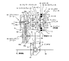
次に、本発明の第2実施形態について説明すると、図3,図4は本発明の第2実施形態としてのハイブリッド車を示すもので、図3はその駆動系(主としてトランスミッション)を示すスケルトン図、図4はその電動機の要部を示す拡大断面図である。なお、図3において、図1と同符号は同様のものを示す。
【0066】
本ハイブリッド車の駆動系は、図3に示すように、モータ4A,合トルク出力機構,第2回転規制手段の各構成が第1実施形態のものと異なっており、他は第1実施形態と同様に構成されている。
つまり、図3に示すように、本実施形態では、動力伝達機構1の入口部分にそなえられるモータ4Aは、エンジン3の回転軸3aに直結されこのエンジン回転軸3aと一体に回転するステータ42と、エンジン回転軸3aと同一軸心線上に配設された中間軸26に直結されこの中間軸26と一体に回転するロータ41と、ケーシング11に固設され回転するステータ42に摺接して電力を供給するブラシ43とをそなえている。そしてロータ41とステータ42との間には、モータクラッチ(第2回転規制手段)59が介装されており、このモータクラッチ59が接続されるとロータ41とステータ42とは一体に回転する。ステータ42は回転するため、ロータ41をインナロータ、ステータ42をアウタロータとも称する。
【0067】
なお、ステータ42とブラシ43との摺接部分については、図4に示すように、スリップリングを適用することが好ましい。つまり、ステータ42と一体回転する円筒部44(ここでは、エンジン回転軸3aに直結されている)に集電環45を設け、この集電環45の外周にブラシ43を摺接させることで、スリップリングを構成し、集電環45とブラシ43とを確実に摺接できるようするとともに、この摺接部の耐久性を確保できるようにすることができる。なお、46はリード線である。
【0068】
これ以外の部分は、第1実施形態と同様であるので、説明は省略する。
本実施形態においても、フォワードクラッチ15,リバースブレーキ14,モータクラッチ59,エンジンクラッチ56,ステータブレーキ58は、何れも油圧アクチュエータによって摩擦係合される湿式多板式の油圧式摩擦係合装置であって、油圧制御回路(図示略)から供給される作動油によって摩擦係合するようになっている。
【0069】
表3に示すように、これらのクラッチ15,59,56及びブレーキ14,58を適宜係脱することで、様々な動力伝達状態が達成される。
【0070】
【表3】
【0071】
なお、このときのモータ4の回転(ステータ42の回転)は、エンジン3と同方向であって、エンジン3と等速度となる。
また、車両停止中にモータ4を発電機として駆動して充電を行なう場合にも、フォワードクラッチ15,リバースブレーキ14及びエンジンクラッチ56をともに結合してモータクラッチ59及びステータブレーキ58は開放する[表3(b)参照]。これにより、CVT6の入力軸61にモータ4やエンジン3の回転は伝達されず、且つ、エンジン3とモータ4(ステータ42)とが連動するようになる。そして、エンジン3でモータ4を回転させればモータ4が発電機として機能して発電が行なわれ充電を行なうことができる。このときのモータ4の回転も、エンジンと同方向で等速度となる。
【0072】
車両を前進発進させる場合や低速走行させる場合には、フォワードクラッチ15及びエンジンクラッチ56を接続状態として、リバースブレーキ14,モータクラッチ59及びステータブレーキ58は開放状態とする[表3(c)参照]。ここで、エンジン3を回転させるとともに、タービン41の回転がエンジン回転と同方向になるようにモータ4を作動させる。この場合、エンジン出力の一部によってモータは発電機として運転される。
【0073】
これにより、中間軸26はエンジンと同方向に回転し、フォワードクラッチ15が結合されてリバースブレーキ14が開放されているので、サンギヤ12aとキャリア12cとが一体回転し、CVT6の入力軸61がエンジン3と同方向に回転駆動され、エンジン3及びモータ4からCVT6に前進方向の回転力が入力されることになり車両は前進発進する。低速時にはこの状態を維持し、速度の上昇に応じてモータ(電動状態又は発電状態)4の回転速度、即ち、タービン41とステータ42との相対回転速度を低下させていく。
【0074】
また、エンジン3のみで車両を走行させる場合には、フォワードクラッチ15及びエンジンクラッチ56を接続状態、リバースブレーキ14,モータクラッチ59及びステータブレーキ58は開放状態として、モータ4の速度(タービン41とステータ42との相対回転速度)を低下させこの速度が略0になった時点で、モータクラッチ59を接続する[表3(d)参照]。これにより、タービン41とステータ42とが一体回転するようになり、中間軸26がエンジン3と一体回転する。フォワードクラッチ15が結合されてリバースブレーキ14が開放されているので、サンギヤ12aとキャリア12cとが一体回転し、CVT6の入力軸61がエンジン3と同方向に回転駆動され、エンジン3からCVT6に前進方向の回転力が入力されることになり車両は前進走行する。
【0075】
さらに、走行中にモータ4により発電を行なう場合には、エンジン3のみでの走行状態、即ち、フォワードクラッチ15,エンジンクラッチ56及びモータクラッチ59を接続し、リバースブレーキ14及びステータブレーキ58は開放した状態から、モータクラッチ59を開放する[表3(f)参照]。そして、これとともに、モータ4を発電機として機能させ、エンジン出力を上げる。これにより、エンジン3の出力は、一部をモータ4による発電に用いられ残りを車両の走行に用いられる。
【0076】
また、エンジン3のみでの走行状態においてエンジントルクを増幅させたい場合にも、フォワードクラッチ15,エンジンクラッチ56及びモータクラッチ59を接続し、リバースブレーキ14及びステータブレーキ58は開放した状態から、モータクラッチ59を開放する[表3(g)参照]。そして、これとともに、モータ4を発電機として機能させた時のモータトルクをエンジントルクよりも大きくすれば駆動力としてのトルクを増幅させることができる。
【0077】
また、エンジン3とモータ4との両方を用いて車両を走行させている状態、即ち、フォワードクラッチ15及びエンジンクラッチ56を接続し、リバースブレーキ14,モータクラッチ59及びステータブレーキ58は開放した状態で[表3(e)参照]、エンジントルクとモータトルクとを出力する。
エンジンのみでの走行状態、即ち、リバースブレーキ14,モータクラッチ59及びエンジンクラッチ56を接続して、フォワードクラッチ15及びステータブレーキ58を開放した状態[表3(d)参照]で、緩減速回生制動条件(例えばアクセルオフ)が成立した場合には、図2(h)に示すように、モータクラッチ59を開放しながらモータ4を発電状態にするとともに、CVT6をローギヤ側に制御してエンジン出力を下げると、エンジンブレーキ相当の減速度で車両を減速させることができる。
【0078】
更に減速が必要な場合には、エンジンクラッチ56を接続状態から開放状態に切り替えて、エンジン出力を必要最小限に下げるとともにステータブレーキ58を拘束すると、モータ4のみの回生制動により、エンジンブレーキ相当以上の減速度で車両を減速させることができる。
なお、必要最低限のエンジン出力とは、第1実施形態と同様であるので、説明を省略する。
【0079】
さらに、車両を後退させる場合には、リバースブレーキ14及びエンジンクラッチ56を接続状態として、フォワードクラッチ14,モータクラッチ59及びステータブレーキ58は開放状態とする[表3(i)参照]。ここで、エンジン3を回転させると同時にモータ4を発電状態にすると、中間軸26がエンジン3と同方向に回転して、回転方向切替機構12のサンギヤ12aに伝達される。リバースブレーキ14が接続されてフォワードクラッチ15が開放されているので、キャリア12cはサンギヤ12aと逆方向(したがって、エンジンと逆方向)に回転する。このキャリア12cの回転により、CVT6の入力軸61がエンジン3と逆方向に回転駆動され、エンジン3からCVT6に後退方向の回転力が入力されることになり車両は後退する。
【0080】
また、モータ4の出力によって車両を後退させる場合には、フォワードクラッチ15及びステータブレーキ58を接続状態として、リバースブレーキ14,モータクラッチ59及びエンジンクラッチ56は開放状態とする[表3(j)参照]。ここで、エンジン3を必要最低限回転させるとともにモータ4をエンジン3と逆方向に回転させる。これにより、中間軸26がモータ4と同方向に回転して、回転方向切替機構12のサンギヤ12aに伝達される。フォワードクラッチ15が接続されてバースブレーキ14が開放されているので、キャリア12cはモータ4のロータ41と同方向(したがって、エンジンと逆方向)に回転する。このキャリア12cの回転により、CVT6の入力軸61がエンジン3と逆方向に回転駆動され、モータ4からCVT6に後退方向の回転力が入力されることになり車両は後退する。
【0081】
本発明の第2実施形態としてのハイブリッド車は、上述のように構成されているので、車両の走行用駆動源としてモータ4を用いずにエンジンのみを用いる場合[表3(d)]には、モータ4のロータ41を停止させるので、不要なモータの回転を防止して、エネルギ損失を抑制することができ、モータの発熱を抑制することができる。これにより、モータ周囲への熱影響を抑制することができる。
【0082】
また、モータ4のロータ41とステータ42との相対回転数を制御することで駆動力の伝達状態を制御する方式なので、常時、電動機の回転速度を抑え易くなる。
例えば、エンジン3出力にモータ4の出力も加えて走行する場合にも、モータ4は、エンジン出力に出力を加える分だけステータ42とロータ41との間に差回転を与えればよく、モータ4の実質的な回転速度(ステータ42とロータ41との相対回転速度)を低く抑えることができる。
【0083】
この結果、モータの回転を制御するためのバッテリの必要電圧を抑えることができる。したがって、モータの回転を制御するためのバッテリ電圧は低いものでよく、バッテリにかかるコストを削減することや、バッテリの重量を削減することが可能になり、ひいては車両の重量やコストを抑えることができ、ハイブリッド車の実用性を高めることができる。
【0084】
特に、回生制動時には、エンジンクラッチ56を開放状態に、ステータブレーキ58を接続状態にすることによって、エンジン3とモータ4とを切り離して効率よくエネルギを回生できるので、これによりエネルギ効率が向上する利点もある。
もちろん、トルクコンバータを省略することができるので、構造の簡素化やコスト低減上も有利になる。
また、変速機としてCVTを用いることにより、エンジンとモータとを効率良く運転して、燃費の向上と走行性能の向上との両立できる。
【0085】
[その他]
以上、本発明の実施形態を説明したが、本発明はかかる実施形態に限定されるものではなく、本発明の趣旨を逸脱しない範囲で種々変形して実施することができる。
【0086】
つまり、本発明は、内燃機関と電動機との両方又は一方の回転を変速機によって変速して駆動輪に伝達し走行するハイブリッド車であって、電動機を、ステータと、ロータと、ロータとステータとの相対回転を適宜規制する回転規制手段とをそなえるようにして、ロータに接続された電動機出力軸と変速機の入力軸との間に回転方向切替機構をそなえ、ステータが内燃機関の回転軸に接続され回転自在に装備されていればよく、他の構成は、上述の実施形態のものに限定されない。
【0087】
例えば、変速機として、ベルト式無段変速機のほかにトロイダル式無段変速機を用いたり、或いは、有段変速機を用いたりすることも考えられる。
また、回転規制手段も、ブレーキ機構を用いたものに限定されるものではない。
【0088】
【発明の効果】
以上詳述したように、請求項1記載の本発明のハイブリッド車によれば、モータのロータとステータとの相対回転数を制御することで駆動力の伝達状態を制御する方式なので、電動機の回転速度を抑え易くなり、電動機の回転を制御するためのバッテリの必要電圧を抑えるうえで有利になる。また、構造の簡素化やコスト低減上も有利になるうえに、回生制動時には、断接手段によって、電動機の出力軸と合トルク出力機構との間の動力伝達は維持しながら内燃機関の出力軸と合トルク出力機構との間の動力伝達を遮断することにより、内燃機関と電動機とを切り離して効率よくエネルギを回生できるので、これによりエネルギ効率が向上する利点もある。
【0089】
請求項2,3記載の本発明のハイブリッド車によれば、電動機の回転速度を抑えることができ、電動機の回転を制御するためのバッテリの必要電圧を抑えることができる。したがって、電動機の回転を制御するためのバッテリにかかるコストを削減することや、バッテリの重量を削減することが可能になり、ひいては車両の重量やコストを抑えることができ、ハイブリッド車の実用性を高めることができる。
【0090】
請求項4記載の本発明のハイブリッド車によれば、電動機を用いずに内燃機関のみを用いて車両を駆動する場合には、電動機の作動を停止させるので、不要な電動機の作動を防止して、エネルギ損失を抑制することができ、モータの発熱を抑制することができる。これにより、電動機周囲への熱影響を抑制することができる。また、電動機を比較的低速で用い易くなるため、電動機の作動時の回転速度を抑えて、電動機の回転を制御するためのバッテリの必要電圧をより抑えることができる。
【0091】
請求項5,6記載の本発明のハイブリッド車によれば、回転方向切替機構により、回転方向の切り替えを、遊星歯車式動力伝達機構とは独立して構成することができ、電動機の回転速度をより低速に抑え易くなる。
また、変速機として無段変速機を用いることにより、エンジンとモータとを効率良く運転して、燃費の向上と走行性能の向上との両立できる(請求項7)。
【図面の簡単な説明】
【図1】本発明の第1実施形態としてのハイブリッド車の駆動系(主としてトランスミッション)を示すスケルトン図である。
【図2】本発明の第1実施形態としてのハイブリッド車の駆動系におけるプラネタリギヤの各要素の共線図であり、作動態様毎にそれぞれ(a)〜(j)に示す。
【図3】本発明の第2実施形態としてのハイブリッド車の駆動系(主としてトランスミッション)を示すスケルトン図である。
【図4】本発明の第2実施形態としてのハイブリッド車の駆動系におけるプラネタリギヤの各要素の共線図であり、作動態様毎にそれぞれ(a)〜(j)に示す。
【図5】従来技術(特許文献1)のハイブリッド車の駆動系(主としてトランスミッション)を示すスケルトン図である。
【図6】従来技術(特許文献2)のハイブリッド車の駆動系(主としてトランスミッション)を示すスケルトン図である。
【図7】従来技術(特許文献2)のハイブリッド車の駆動系におけるプラネタリギヤの各要素の共線図であり、作動態様毎にそれぞれ(a)〜(j)に示す。
【符号の説明】
1 トランスミッション
2 プラネタリギヤ機構
3 エンジンの回転軸
4 電動モータ
6 CVT
7 カウンタシャフト
8 デファレンシャルギヤ
9L,9R 車輪軸(車輪駆動軸)
11 トランスミッションケーシング
12 回転方向切替機構
12A プラネタリギヤ機構
12a サンギヤ
12ba インナピニオン
12bb アウタピニオン
12c キャリア
12d リングギヤ
14 リバースブレーキ
15 フォワードクラッチ
21 サンギヤ
22 インナピニオン
23 アウタピニオン
24,27 プラネタリキャリア
25 リングギヤ
26 プラネタリピニオン
41 ロータ(回転子)
42 ステ−タ
54 モータブレーキ(第2回転規制手段)
56 エンジンクラッチ(断接手段)
57 サンギヤブレーキ(第1回転規制手段)
58 ステータブレーキ(第1回転規制手段)
59 モータクラッチ(第2回転規制手段)
61 入力軸
62 プライマリプーリ
62a,64a 可動シーブ
62b,64b 固定シーブ
63 ベルト
64 セカンダリプーリ
65 出力軸
66 ギヤ
71 カウンタギヤ
72 カウンタギヤ
81 リングギヤ[0001]
BACKGROUND OF THE INVENTION
The present invention relates to a hybrid vehicle equipped with both an internal combustion engine and an electric motor for driving the vehicle.
[0002]
[Prior art]
In recent years, a hybrid vehicle equipped with both an internal combustion engine (hereinafter referred to as an engine) and an electric motor (hereinafter referred to as an electric motor or simply a motor) for driving the vehicle has been developed (see, for example, Patent Document 1). .
[0003]
That is, as shown in FIG. 5, the hybrid vehicle is configured by combining the
[0004]
A rotation
[0005]
As the rotation
[0006]
Output of rotation from the rotation
[0007]
The
[0008]
A clutch 15 is disposed inside the
[0009]
The continuously
The primary pulley 62 and the secondary pulley 64 have fixed
[0010]
In addition, a planetary gear mechanism that can absorb the rotation of the engine and motor between the engine and motor and the transmission is interposed, and a torque converter is omitted so that the total length of the transmission part can be shortened. (For example, refer to Patent Document 2).
FIG. 6 is a skeleton diagram showing a drive system (mainly transmission) of a hybrid vehicle of the prior art disclosed in
[0011]
The
[0012]
The CVT 6 includes a primary pulley 62 connected to the
[0013]
Further, the rotation of the
[0014]
The carrier clutch 51, ring gear clutch 52, and ring gear brake 53 are all wet multi-plate hydraulic friction engagement devices that are frictionally engaged by a hydraulic actuator, and are supplied from a hydraulic control circuit (not shown). Friction engagement is performed by hydraulic oil. As shown in Table 1, by appropriately disengaging these clutches 51 and 52 and the brake 53, various power transmission states as shown in the alignment chart of FIG. 7 are achieved.
[0015]
[Table 1]
[0016]
Even when charging is performed by driving the electric motor 4 as a generator while the vehicle is stopped, only the ring gear brake 53 is connected, and the carrier clutch 51 and the ring gear clutch 52 are opened (see Table 1 (b)). ). Then, as shown in FIG. 7B, if the electric motor 4 is rotated by the engine, the electric motor 4 functions as a generator to generate power and perform charging. The rotation of the motor 4 at this time is also reverse to the engine. Of course, no power is transmitted to the drive wheels at this time.
[0017]
When the vehicle is driven only by the electric motor 4, only the carrier clutch 51 is connected, and the ring gear clutch 52 and the ring gear brake 53 are opened (see Table 1 (c)). If there is no input from the engine (that is, the sun gear is stopped), the electric motor 4 is rotated in the direction opposite to that of the engine as indicated by a thick solid line in FIG. 7C. Thus, the forward rotational force is input to the
[0018]
On the other hand, when the vehicle is driven only by the engine, the carrier clutch 51 and the ring gear clutch 52 are connected, and the ring gear brake 53 is released (see Table 1 (d)). As a result, as shown in FIG. 7 (d), the
[0019]
When the vehicle is driven using both the engine and the electric motor 4, the carrier clutch 51 and the ring gear clutch 52 are connected and the ring gear brake 53 is released (Table 1). e)). As a result, as shown in FIG. 7 (e), the
[0020]
Further, when electric power is generated by the electric motor 4 during traveling, the carrier clutch 51 and the ring gear clutch 52 are connected and the ring gear brake 53 is released as described above (see Table 1 (f)). As a result, as shown in FIG. 7 (f), the
[0021]
When it is desired to amplify the engine torque when the battery capacity is low and it is desired to avoid starting by the electric motor 4 or when starting at a very low vehicle speed and high load (starting on a steep slope), the engine start (Table 1 (a), After FIG. 7A), the ring gear brake 53 is released and the ring gear clutch 52 is connected, and the carrier clutch 51 remains open (see Table 1 (g)). Here, as indicated by a broken line in FIG. 7G, when the electric motor 4 is in a power generation state, the electric motor 4 becomes an engine torque reaction force, the engine torque is amplified, and the
[0022]
If the carrier clutch 51 is gradually engaged from this state, when this engagement is completed, as shown by the solid line in FIG. 7 (g), the normal running state, that is, the engine running state (FIG. 7 (d)). Or a running state using both the engine and the electric motor 4 (see FIG. 7E), or an engine running state while generating power with the electric motor 4 (see FIG. 7F). be able to.
[0023]
In addition, when a regenerative braking condition (for example, accelerator off or brake on) is satisfied while the vehicle is traveling at a low speed (only with the electric motor 4), the ring gear clutch 52 and the ring gear are set with the carrier clutch 51 in the connected state. The brake 53 is released (see Table 1 (h)). When the electric motor 4 is brought into a power generation state and the
[0024]
Further, when a regenerative braking condition (for example, accelerator off or brake on) is satisfied when the vehicle is traveling at a medium speed or higher (only with the engine or with the engine and the electric motor 4), the carrier clutch 51 and the ring gear The ring gear brake 53 is disengaged with the clutch 52 engaged (see Table 1 (i)). Then, when the electric motor 4 is in a power generation state and the
[0025]
Further, when the vehicle is moved backward by the output of the engine, the carrier clutch 51 is engaged, the ring gear clutch 52 is disengaged, and the ring gear brake 53 is disengaged from the disengaged state (Table 1 (j) reference). By frictionally engaging the ring gear brake 53 and controlling the
[0026]
[Patent Document 1]
JP 2002-118903 A
[Patent Document 2]
JP 2002-171601 A
[0027]
[Problems to be solved by the invention]
By the way, in the above-described prior art, the
[0028]
In recent years, high-voltage batteries have been developed for hybrid vehicles, but in order to obtain a sufficiently high battery voltage, it is necessary to connect a plurality of batteries, which increases the cost of the vehicle and gives consideration to handling high voltages. I need it.
Of course, if you rely on electric motors to drive the vehicle, you will need a corresponding battery capacity, and it is inevitable that the vehicle will increase in weight and cost. If it is used supplementarily, a battery with a smaller capacity may be used. Therefore, even when such a hybrid vehicle is considered, it is desirable to stop the electric motor 4 when not necessary and to operate the electric motor at the lowest possible rotation.
[0029]
The present invention has been devised in view of the above-described problems, and provides a hybrid vehicle in which an electric motor can be operated at as low a rotation as possible and regenerative braking can be performed efficiently. For the purpose.
[0030]
[Means for Solving the Problems]
For this reason, the hybrid vehicle of the present invention (Claim 1) is a hybrid vehicle that travels by shifting the rotation generated by one or both of the internal combustion engine and the electric motor by the transmission and transmitting it to the drive wheels. Is configured to be operated as a generator by being driven to rotate, while maintaining the power transmission between the output shaft of the electric motor and the combined torque output mechanism, the output torque of the internal combustion engine and the output torque of the electric motor A combined torque output mechanism for output to the transmission side, connection / disconnection means capable of connecting / disconnecting power transmission between the output shaft of the internal combustion engine and the combined torque output mechanism, First rotation restricting means capable of restricting rotation of the output shaft; The combined torque output mechanism is provided coaxially with the rotation shafts of the internal combustion engine and the electric motor, and is connected to the rotation shaft of the internal combustion engine via the connecting / disconnecting means, and the electric motor A second input rotation element connected to the rotation shaft of the output and an output rotation element, allowing a differential between the first input rotation element and the output rotation element, and the first input rotation element and the output rotation element A differential permissible power transmission mechanism that transmits power between the second input rotation element and the output rotation element, wherein the first rotation restricting means includes a casing that accommodates the combined torque output mechanism; A second rotation restricting means interposed between the input rotating element and between the casing and the rotating shaft of the electric motor for restricting the rotation of the rotating shaft of the electric motor; The power transmission mechanism uses the first input rotation element as a sun gear and the second input rotation element as a ring. And Ya, the output rotating element and the planetary carrier is a planetary gear mechanism It is characterized by that.
[0031]
Thus, in the hybrid vehicle of the present invention (Claim 1), when the drive wheels are driven only by the output of the internal combustion engine, the rotor of the electric motor can be stopped, and unnecessary rotation of the motor can be prevented. This can prevent energy loss and suppress heat generation of the motor. In addition, it is easy to suppress the rotation speed during operation of the motor, and it is possible to suppress the voltage of the battery for controlling the rotation of the motor.
[0033]
The An electric motor includes a stator rotatably mounted on a casing that houses the electric motor, a rotor that rotates relative to the stator, and second rotation restricting means that appropriately restricts relative rotation between the rotor and the stator. A brush that is fixed to the casing and is slidably contacted with the electrode on the stator side to supply electricity to the electrode, and the combined torque output mechanism is connected to the rotating shaft of the internal combustion engine via the connecting / disconnecting means. A differential permissible power transmission mechanism comprising the connected stator and the rotor, and allowing a differential between the stator and the rotor to transmit power between the stator and the rotor. Is preferred (claims) 2 ).
[0034]
Between the output shaft of the combined torque output mechanism and the input shaft of the transmission, a normal rotation state in which the rotation of the output shaft of the combined torque output mechanism is output to the input shaft while rotating in the forward direction, and the combined torque output It is preferable that a rotation direction switching mechanism for interchanging a rotation state of the output shaft of the mechanism to be reversed and to be output to the input shaft is interposed (claim). 3 ).
[0035]
The rotation direction switching mechanism includes a planetary gear mechanism having a sun gear connected to the output shaft of the motor, a carrier connected to the input shaft of the transmission, and a ring gear, and between the sun gear and the carrier. In between, a forward clutch for outputting the rotation of the motor output shaft to the input shaft while rotating in the forward direction is interposed, and the rotation of the motor output shaft is reversed between the ring gear and the casing of the rotation direction switching mechanism. It is preferable that a reverse brake is provided to output to the input shaft. 4 ).
Preferably, the transmission is a continuously variable transmission. 5 ).
[0036]
As shown in FIG. 1, the drive system of this hybrid vehicle includes a
[0037]
That is, as shown in FIG. 1, the drive system of the hybrid vehicle is configured by combining the
A planetary gear type power transmission mechanism (simply referred to as a planetary gear mechanism) 2A is provided at the entrance of the
[0038]
In addition, power transmission between the output shaft of the motor 4 and the planetary gear mechanism (combined torque output mechanism) 2A is maintained between the
[0039]
The
[0040]
The
[0041]
Accordingly, the
[0042]
Further, between the sun gear (first input rotation element) 21 and the
The rotation
[0043]
Therefore, the rotation of the
[0044]
On the other hand, if the forward clutch 15 is released and the reverse brake 14 is coupled, the rotation
[0045]
If the forward clutch 15 and the reverse brake 14 are both coupled, the
[0046]
The rotational speed ω of the
[0047]
The
[0048]
Further, the rotation of the
[0049]
Since the counter shaft 7 is interposed between the
The forward clutch 15, reverse brake 14, motor brake 54, engine clutch 56 and Sun Each of the gear brakes 57 is a wet multi-plate hydraulic friction engagement device that is frictionally engaged by a hydraulic actuator, and is frictionally engaged by hydraulic oil supplied from a hydraulic control circuit (not shown). ing. As shown in Table 2, by appropriately disengaging these clutches 15 and 56 and brakes 14, 54 and 57, various power transmission states as shown in the collinear diagram of FIG. 2 are achieved.
[0050]
[Table 2]
[0051]
Note that the rotation of the motor 4 at this time is in the same direction as the
Also, when the motor 4 is driven as a generator for charging while the vehicle is stopped, the forward clutch 15, the reverse brake 14 and the engine clutch 56 are coupled together to connect the motor brake 54 and Sun The gear brake 57 is released [see Table 2 (b)]. Accordingly, the rotation of the motor 4 and the
[0052]
When the vehicle starts to move forward or travels at a low speed, the reverse brake 14 and the engine clutch 56 are connected, and the forward clutch 15, the motor brake 54, and Sun The gear brake 57 is opened [see Table 2 (c)]. Here, as shown in FIG. 2C, the
[0053]
When the vehicle is driven only by the
[0054]
Further, when the vehicle is driven using the driving forces of both the
[0055]
Further, when power is generated by the motor 4 during traveling, the traveling state of the
[0056]
Also, when it is desired to amplify the engine torque in the traveling state with only the
[0057]
Further, when the vehicle is driven using the driving force of both the
The traveling state of the engine alone, that is, the reverse brake 14, the motor brake 54 and the engine clutch 56 are connected, and the forward clutch 15 and Sun In the state where the gear brake 57 is released [see Table 2 (d)], when the slow deceleration regenerative braking condition (for example, accelerator off) is satisfied, the motor brake 54 is released as shown in FIG. 2 (h). However, when the motor 4 is set in the power generation state and the
[0058]
If further deceleration is required, the engine clutch 56 is switched from the connected state to the released state, the engine output is reduced to the minimum necessary, and the sun gear brake 57 is restrained. The vehicle can be decelerated at a deceleration of.
Note that the above-mentioned minimum required engine output refers to the driving of auxiliary machinery driven by the
[0059]
Further, when the vehicle is moved backward by the driving force of the
[0060]
When the vehicle is driven backward by the driving force of the motor 4, the reverse brake 14 and the sun gear brake 56 are set in the connected state, and the forward clutch 15, the motor brake 54, and the engine clutch 56 are set in the open state [Table 2 (j) reference]. Here, as shown in FIG. 2 (j), the
[0061]
Since the hybrid vehicle as the first embodiment of the present invention is configured as described above, when only the engine is used without using the motor 4 as the vehicle driving source [Table 2 (d), FIG. (See (d)), since the
[0062]
Further, since the transmission state of the driving force is controlled by controlling the relative rotational speed between the
As a result, the required voltage of the battery for controlling the rotation of the motor can be suppressed. Therefore, the battery voltage for controlling the rotation of the motor may be low, so that it is possible to reduce the cost of the battery, reduce the weight of the battery, and consequently reduce the weight and cost of the vehicle. This can improve the practicality of the hybrid vehicle.
[0063]
In particular, at the time of regenerative braking, the engine clutch 56 is in the released state, Sun By setting the gear brake 57 in the connected state, the
Of course, the torque converter can be omitted, which is advantageous in terms of simplification of the structure and cost reduction.
[0064]
Since the
Further, by using CVT as the transmission, it is possible to efficiently drive the engine and the motor, and to improve both fuel efficiency and driving performance.
[0065]
[Second Embodiment]
Next, a second embodiment of the present invention will be described. FIGS. 3 and 4 show a hybrid vehicle as a second embodiment of the present invention, and FIG. 3 is a skeleton diagram showing a drive system (mainly a transmission). FIG. 4 is an enlarged sectional view showing a main part of the electric motor. In FIG. 3, the same reference numerals as those in FIG.
[0066]
As shown in FIG. 3, the drive system of this hybrid vehicle is different from that of the first embodiment in the configuration of the motor 4A, the combined torque output mechanism, and the second rotation restricting means. It is constituted similarly.
That is, as shown in FIG. 3, in this embodiment, the motor 4A provided at the inlet portion of the
[0067]
Note that a slip ring is preferably applied to the sliding contact portion between the
[0068]
Since other parts are the same as those in the first embodiment, description thereof will be omitted.
Also in this embodiment, the forward clutch 15, the reverse brake 14, the motor clutch 59, the engine clutch 56, and the stator brake 58 are all wet multi-plate hydraulic friction engagement devices that are frictionally engaged by a hydraulic actuator. The hydraulic oil is frictionally engaged by hydraulic oil supplied from a hydraulic control circuit (not shown).
[0069]
As shown in Table 3, various power transmission states are achieved by appropriately disengaging these clutches 15, 59, 56 and brakes 14, 58.
[0070]
[Table 3]
[0071]
The rotation of the motor 4 (rotation of the stator 42) at this time is in the same direction as the
In addition, when charging is performed by driving the motor 4 as a generator while the vehicle is stopped, the forward clutch 15, the reverse brake 14 and the engine clutch 56 are coupled together to release the motor clutch 59 and the stator brake 58 [Table 3 (b)]. As a result, the rotation of the motor 4 and the
[0072]
When the vehicle starts to move forward or travels at a low speed, the forward clutch 15 and the engine clutch 56 are connected, and the reverse brake 14, the motor clutch 59, and the stator brake 58 are opened [see Table 3 (c)]. . Here, the
[0073]
As a result, the
[0074]
When the vehicle is driven only by the
[0075]
Further, when power is generated by the motor 4 during traveling, the traveling state of the
[0076]
Also, when it is desired to amplify the engine torque in the running state with only the
[0077]
Further, the vehicle is driven using both the
Slow deceleration regenerative braking in a traveling state with only the engine, that is, in a state in which the reverse brake 14, the motor clutch 59 and the engine clutch 56 are connected and the forward clutch 15 and the stator brake 58 are released [see Table 3 (d)]. When the condition (for example, accelerator off) is satisfied, as shown in FIG. 2 (h), the motor 4 is set in the power generation state while the motor clutch 59 is released, and the engine output is controlled by controlling the
[0078]
If further deceleration is required, the engine clutch 56 is switched from the connected state to the released state, the engine output is reduced to the necessary minimum, and the stator brake 58 is restrained. The vehicle can be decelerated at a deceleration of.
The minimum required engine output is the same as that in the first embodiment, and a description thereof will be omitted.
[0079]
Further, when the vehicle is to be moved backward, the reverse brake 14 and the engine clutch 56 are connected, and the forward clutch 14, the motor clutch 59, and the stator brake 58 are released [see Table 3 (i)]. Here, when the motor 4 is in a power generation state at the same time as the
[0080]
Further, when the vehicle is moved backward by the output of the motor 4, the forward clutch 15 and the stator brake 58 are connected, and the reverse brake 14, the motor clutch 59, and the engine clutch 56 are released [see Table 3 (j). ]. Here, the
[0081]
Since the hybrid vehicle as the second embodiment of the present invention is configured as described above, when only the engine is used as the vehicle driving source for the vehicle without using the motor 4 [Table 3 (d)] Since the
[0082]
Further, since the transmission state of the driving force is controlled by controlling the relative rotational speed between the
For example, when traveling with the output of the motor 4 added to the output of the
[0083]
As a result, the required voltage of the battery for controlling the rotation of the motor can be suppressed. Therefore, the battery voltage for controlling the rotation of the motor may be low, so that it is possible to reduce the cost of the battery, reduce the weight of the battery, and consequently reduce the weight and cost of the vehicle. This can improve the practicality of the hybrid vehicle.
[0084]
In particular, at the time of regenerative braking, the engine clutch 56 is released and the stator brake 58 is connected, so that the
Of course, the torque converter can be omitted, which is advantageous in terms of simplification of the structure and cost reduction.
In addition, by using CVT as a transmission, it is possible to drive the engine and the motor efficiently, and to improve both fuel efficiency and driving performance.
[0085]
[Others]
Although the embodiments of the present invention have been described above, the present invention is not limited to such embodiments, and various modifications can be made without departing from the spirit of the present invention.
[0086]
That is, the present invention is a hybrid vehicle that travels by shifting the rotation of both or one of the internal combustion engine and the electric motor by the transmission and transmitting them to the drive wheels. The electric motor includes the stator, the rotor, the rotor, and the stator. A rotation restricting means for appropriately restricting the relative rotation of the motor, a rotation direction switching mechanism is provided between the motor output shaft connected to the rotor and the input shaft of the transmission, and the stator serves as the rotation shaft of the internal combustion engine. The other configuration is not limited to the above-described embodiment as long as it is connected and rotatable.
[0087]
For example, a toroidal continuously variable transmission other than a belt type continuously variable transmission or a stepped transmission may be used as the transmission.
Further, the rotation restricting means is not limited to one using a brake mechanism.
[0088]
【The invention's effect】
As described above in detail, according to the hybrid vehicle of the first aspect of the present invention, since the driving force transmission state is controlled by controlling the relative rotational speed between the rotor of the motor and the stator, the rotation of the motor It becomes easy to suppress the speed, which is advantageous in suppressing the required voltage of the battery for controlling the rotation of the electric motor. In addition, this simplifies the structure and reduces costs, and during regenerative braking, the connecting / disconnecting means maintains the power transmission between the output shaft of the motor and the combined torque output mechanism while maintaining the output shaft of the internal combustion engine. By shutting off the power transmission between the engine and the combined torque output mechanism, the internal combustion engine and the electric motor can be separated and the energy can be efficiently regenerated, which has the advantage of improving the energy efficiency.
[0089]
According to the hybrid vehicle of the present invention, the rotational speed of the electric motor can be suppressed, and the necessary voltage of the battery for controlling the rotation of the electric motor can be suppressed. Therefore, it is possible to reduce the cost of the battery for controlling the rotation of the electric motor, and to reduce the weight of the battery, which in turn can reduce the weight and cost of the vehicle. Can be increased.
[0090]
According to the hybrid vehicle of the present invention described in claim 4, when the vehicle is driven using only the internal combustion engine without using the electric motor, the operation of the electric motor is stopped, so that unnecessary operation of the electric motor is prevented. Energy loss can be suppressed and heat generation of the motor can be suppressed. Thereby, the thermal influence to the motor periphery can be suppressed. Moreover, since it becomes easy to use an electric motor at comparatively low speed, the required voltage of the battery for controlling rotation of an electric motor can be suppressed more by suppressing the rotational speed at the time of the action | operation of an electric motor.
[0091]
According to the hybrid vehicle of the present invention described in
In addition, by using a continuously variable transmission as the transmission, the engine and the motor can be efficiently driven to achieve both improvement in fuel consumption and improvement in running performance.
[Brief description of the drawings]
FIG. 1 is a skeleton diagram showing a drive system (mainly a transmission) of a hybrid vehicle as a first embodiment of the present invention.
FIG. 2 is a collinear diagram of each element of a planetary gear in the drive system of the hybrid vehicle as the first embodiment of the present invention, and is shown in (a) to (j) for each operation mode.
FIG. 3 is a skeleton diagram showing a drive system (mainly transmission) of a hybrid vehicle as a second embodiment of the present invention.
FIG. 4 is a collinear diagram of each element of a planetary gear in a drive system of a hybrid vehicle as a second embodiment of the present invention, and is shown in (a) to (j) for each operation mode.
FIG. 5 is a skeleton diagram showing a drive system (mainly transmission) of a hybrid vehicle according to the prior art (Patent Document 1).
FIG. 6 is a skeleton diagram showing a drive system (mainly transmission) of a hybrid vehicle of the prior art (Patent Document 2).
FIG. 7 is a collinear diagram of each element of a planetary gear in a drive system of a hybrid vehicle of the prior art (Patent Document 2), and is shown in (a) to (j) for each operation mode.
[Explanation of symbols]
1 Transmission
2 Planetary gear mechanism
3 Engine rotation shaft
4 Electric motor
6 CVT
7 Counter shaft
8 Differential gear
9L, 9R Wheel shaft (wheel drive shaft)
11 Transmission casing
12 Rotation direction switching mechanism
12A planetary gear mechanism
12a Sungear
12ba Inner pinion
12bb outer pinion
12c career
12d ring gear
14 Reverse brake
15 Forward clutch
21 Sungear
22 Inner Pinion
23 Outer Pinion
24,27 Planetary Carrier
25 Ring gear
26 Planetary pinion
41 Rotor
42 STATOR
54 Motor brake (second rotation restricting means)
56 Engine clutch (connection / disconnection means)
57 Sun Gear brake (first rotation restricting means)
58 Stator brake (first rotation restricting means)
59 Motor clutch (second rotation restricting means)
61 Input shaft
62 Primary pulley
62a, 64a Movable sheave
62b, 64b fixed sheave
63 Belt
64 Secondary pulley
65 output shaft
66 Gear
71 counter gear
72 Counter gear
81 Ring gear
Claims (5)
該電動機は回転駆動されることで発電機として作動しうるように構成され、
該内燃機関の出力トルクと電動機の出力トルクとを集合させて該変速機側に出力する合トルク出力機構と、
該電動機の出力軸と該合トルク出力機構との間の動力伝達は維持しながら該内燃機関の出力軸と該合トルク出力機構との間の動力伝達を断接しうる断接手段と、
該内燃機関の出力軸の回転を規制しうる第1回転規制手段と、をそなえ、
該合トルク出力機構は、該内燃機関及び該電動機の回転軸と同軸上に設けられ、該内燃機関の回転軸に該断接手段を介して接続された第1入力回転要素と、該電動機の回転軸に接続された第2入力回転要素と、出力回転要素とをそなえ、該第1入力回転要素と該出力回転要素との間の差動を許容して該第1入力回転要素及び該第2入力回転要素と該出力回転要素との間で動力を伝達する差動許容型動力伝達機構であり、
該第1回転規制手段は、該合トルク出力機構を収容するケーシングと、該第1入力回転要素との間に介装され、
該ケーシングと、該電動機の回転軸との間に該電動機の回転軸の回転を規制しうる第2回転規制手段が介装され、
該差動許容型動力伝達機構は、該第1入力回転要素をサンギヤとし、第2入力回転要素をリングギヤとし、該出力回転要素をプラネタリキャリアとする、遊星歯車機構である
ていることを特徴とする、ハイブリッド車。A hybrid vehicle that travels by transmitting the rotation generated by both or one of the internal combustion engine and the electric motor by a transmission to a drive wheel,
The electric motor is configured to operate as a generator by being rotationally driven,
A combined torque output mechanism for collecting the output torque of the internal combustion engine and the output torque of the electric motor and outputting them to the transmission side;
Connecting / disconnecting means capable of connecting / disconnecting power transmission between the output shaft of the internal combustion engine and the combined torque output mechanism while maintaining power transmission between the output shaft of the electric motor and the combined torque output mechanism;
First rotation restricting means capable of restricting rotation of the output shaft of the internal combustion engine ;
The combined torque output mechanism is provided coaxially with the rotation shafts of the internal combustion engine and the electric motor, connected to the rotation shaft of the internal combustion engine via the connecting / disconnecting means, and the electric motor A second input rotation element connected to the rotation shaft; and an output rotation element. The differential between the first input rotation element and the output rotation element is allowed, and the first input rotation element and the first rotation element are allowed. A differential permissible power transmission mechanism that transmits power between a two-input rotary element and the output rotary element;
The first rotation restricting means is interposed between the casing accommodating the combined torque output mechanism and the first input rotation element,
A second rotation regulating means capable of regulating the rotation of the rotating shaft of the electric motor is interposed between the casing and the rotating shaft of the electric motor;
The differential permissible power transmission mechanism is a planetary gear mechanism in which the first input rotation element is a sun gear, the second input rotation element is a ring gear, and the output rotation element is a planetary carrier . This is a hybrid vehicle.
該合トルク出力機構は、該内燃機関の回転軸に該断接手段を介して接続された該ステータと、該ロータとをそなえ、該ステータと、該ロータとの間の差動を許容して該ステータと、該ロータとの間で動力を伝達する差動許容型動力伝達機構である
ことを特徴とする、請求項1記載のハイブリッド車。The electric motor includes a stator rotatably mounted on a casing that accommodates the electric motor, a rotor that rotates relative to the stator, and second rotation restricting means that appropriately restricts relative rotation between the rotor and the stator. And a brush that is fixed to the casing and is in sliding contact with the electrode on the stator and supplies electricity to the electrode,
The combined torque output mechanism includes the stator connected to the rotating shaft of the internal combustion engine via the connecting / disconnecting means and the rotor, and allows a differential between the stator and the rotor. The hybrid vehicle according to claim 1, wherein the hybrid vehicle is a differential permissible power transmission mechanism that transmits power between the stator and the rotor.
ことを特徴とする、請求項1又は2記載のハイブリッド車。Between the output shaft of the combined torque output mechanism and the input shaft of the transmission, a normal rotation state in which the rotation of the output shaft of the combined torque output mechanism is output to the input shaft while rotating in the forward direction and the combined torque output The hybrid vehicle according to claim 1 or 2 , further comprising a rotation direction switching mechanism for switching between a reverse rotation state in which the rotation of the output shaft of the mechanism is reversed and output to the input shaft.
該サンギヤと該キャリアとの間に該電動機出力軸の回転を正転のまま該入力軸に出力するためのフォワードクラッチが介装され、該リングギヤと該回転方向切替機構のケーシングとの間に該電動機出力軸の回転を逆転させて該入力軸に出力するリバースブレーキが介装されている
ことを特徴とする、請求項3記載のハイブリッド車。The rotation direction switching mechanism includes a planetary gear mechanism having a sun gear connected to the motor output shaft, a carrier connected to the input shaft of the transmission, and a ring gear.
A forward clutch for outputting the rotation of the motor output shaft to the input shaft while rotating in the forward direction is interposed between the sun gear and the carrier, and between the ring gear and the casing of the rotation direction switching mechanism, 4. The hybrid vehicle according to claim 3 , further comprising a reverse brake for reversing the rotation of the output shaft of the electric motor and outputting it to the input shaft.
Priority Applications (1)
| Application Number | Priority Date | Filing Date | Title |
|---|---|---|---|
| JP2003044831A JP3852414B2 (en) | 2003-02-21 | 2003-02-21 | Hybrid car |
Applications Claiming Priority (1)
| Application Number | Priority Date | Filing Date | Title |
|---|---|---|---|
| JP2003044831A JP3852414B2 (en) | 2003-02-21 | 2003-02-21 | Hybrid car |
Publications (2)
| Publication Number | Publication Date |
|---|---|
| JP2004249937A JP2004249937A (en) | 2004-09-09 |
| JP3852414B2 true JP3852414B2 (en) | 2006-11-29 |
Family
ID=33027423
Family Applications (1)
| Application Number | Title | Priority Date | Filing Date |
|---|---|---|---|
| JP2003044831A Expired - Fee Related JP3852414B2 (en) | 2003-02-21 | 2003-02-21 | Hybrid car |
Country Status (1)
| Country | Link |
|---|---|
| JP (1) | JP3852414B2 (en) |
Cited By (1)
| Publication number | Priority date | Publication date | Assignee | Title |
|---|---|---|---|---|
| CN102225684A (en) * | 2011-05-03 | 2011-10-26 | 重庆大学 | Power transmission system of hybrid electric vehicle (HEV) |
Families Citing this family (8)
| Publication number | Priority date | Publication date | Assignee | Title |
|---|---|---|---|---|
| JP4900693B2 (en) * | 2006-11-27 | 2012-03-21 | アイシン・エィ・ダブリュ株式会社 | Hybrid drive unit |
| JP2010155517A (en) * | 2008-12-26 | 2010-07-15 | Honda Motor Co Ltd | Power transmission device for hybrid vehicle |
| JP2010269765A (en) * | 2009-05-25 | 2010-12-02 | Ud Trucks Corp | Power transmitting mechanism for hybrid vehicle |
| BR102012004079A2 (en) * | 2011-02-24 | 2018-04-03 | Yang Tai-Her | "DUAL DRIVE ELECTRIC MACHINE WITH CONTROLABLE EPICYCLE GEAR GAMES" |
| TWI591942B (en) * | 2011-02-24 | 2017-07-11 | 楊泰和 | Dual-drive electric machine having controllable epicycle gear set |
| JP5760580B2 (en) * | 2011-03-25 | 2015-08-12 | マツダ株式会社 | Control device for automatic transmission |
| CN113165499A (en) * | 2018-12-14 | 2021-07-23 | Gkn汽车有限公司 | Transmission assembly for hybrid drive |
| CN113879102A (en) * | 2021-10-28 | 2022-01-04 | 池洪 | Birotor motor and hybrid electric vehicle comprising same |
-
2003
- 2003-02-21 JP JP2003044831A patent/JP3852414B2/en not_active Expired - Fee Related
Cited By (1)
| Publication number | Priority date | Publication date | Assignee | Title |
|---|---|---|---|---|
| CN102225684A (en) * | 2011-05-03 | 2011-10-26 | 重庆大学 | Power transmission system of hybrid electric vehicle (HEV) |
Also Published As
| Publication number | Publication date |
|---|---|
| JP2004249937A (en) | 2004-09-09 |
Similar Documents
| Publication | Publication Date | Title |
|---|---|---|
| US7174979B2 (en) | Hybrid vehicle | |
| EP3106338B1 (en) | Drive unit for hybrid vehicle | |
| EP2351661B1 (en) | Hybrid power driving system and gear position operation method thereof | |
| JP4228954B2 (en) | Hybrid vehicle drive system | |
| US6302227B1 (en) | Hybrid powered vehicle | |
| CN102862470B (en) | The multiple mode power shunting dynamical system of electric vehicle | |
| JP3935673B2 (en) | Hybrid propulsion device group consisting of double planetary gears | |
| JP5670562B2 (en) | Hybrid propulsion system | |
| JP4134998B2 (en) | Hybrid vehicle drive system | |
| JP4779935B2 (en) | Hybrid drive unit | |
| WO2008075760A1 (en) | Hybrid drive device | |
| JP3743444B2 (en) | Drive device for hybrid vehicle | |
| JP2008114812A (en) | Hybrid driving device | |
| JP5827458B2 (en) | Hybrid-type power vehicle travel drive device and method for driving the hybrid-type power vehicle | |
| KR100986564B1 (en) | power train of an hybrid electric vehicle and manipulating method thereof | |
| JP3852414B2 (en) | Hybrid car | |
| JP4779936B2 (en) | Hybrid drive unit | |
| JP3815417B2 (en) | Powertrain structure for vehicles | |
| JP4400676B2 (en) | Hybrid vehicle drive system | |
| JP2004210116A (en) | Drive device of hybrid vehicle | |
| JP3852411B2 (en) | Hybrid car | |
| JP2009257574A (en) | Driving unit | |
| JP2004243838A (en) | Hybrid vehicle | |
| JP3214424B2 (en) | Hybrid drive | |
| KR20190025415A (en) | Power train for hybrid vehicles |
Legal Events
| Date | Code | Title | Description |
|---|---|---|---|
| A621 | Written request for application examination |
Free format text: JAPANESE INTERMEDIATE CODE: A621 Effective date: 20050518 |
|
| A131 | Notification of reasons for refusal |
Free format text: JAPANESE INTERMEDIATE CODE: A131 Effective date: 20060509 |
|
| A521 | Request for written amendment filed |
Free format text: JAPANESE INTERMEDIATE CODE: A523 Effective date: 20060710 |
|
| TRDD | Decision of grant or rejection written | ||
| A01 | Written decision to grant a patent or to grant a registration (utility model) |
Free format text: JAPANESE INTERMEDIATE CODE: A01 Effective date: 20060815 |
|
| A61 | First payment of annual fees (during grant procedure) |
Free format text: JAPANESE INTERMEDIATE CODE: A61 Effective date: 20060828 |
|
| R151 | Written notification of patent or utility model registration |
Ref document number: 3852414 Country of ref document: JP Free format text: JAPANESE INTERMEDIATE CODE: R151 |
|
| S531 | Written request for registration of change of domicile |
Free format text: JAPANESE INTERMEDIATE CODE: R313531 |
|
| R350 | Written notification of registration of transfer |
Free format text: JAPANESE INTERMEDIATE CODE: R350 |
|
| FPAY | Renewal fee payment (event date is renewal date of database) |
Free format text: PAYMENT UNTIL: 20090915 Year of fee payment: 3 |
|
| FPAY | Renewal fee payment (event date is renewal date of database) |
Free format text: PAYMENT UNTIL: 20100915 Year of fee payment: 4 |
|
| FPAY | Renewal fee payment (event date is renewal date of database) |
Free format text: PAYMENT UNTIL: 20100915 Year of fee payment: 4 |
|
| FPAY | Renewal fee payment (event date is renewal date of database) |
Free format text: PAYMENT UNTIL: 20110915 Year of fee payment: 5 |
|
| FPAY | Renewal fee payment (event date is renewal date of database) |
Free format text: PAYMENT UNTIL: 20110915 Year of fee payment: 5 |
|
| FPAY | Renewal fee payment (event date is renewal date of database) |
Free format text: PAYMENT UNTIL: 20130915 Year of fee payment: 7 |
|
| FPAY | Renewal fee payment (event date is renewal date of database) |
Free format text: PAYMENT UNTIL: 20130915 Year of fee payment: 7 |
|
| FPAY | Renewal fee payment (event date is renewal date of database) |
Free format text: PAYMENT UNTIL: 20140915 Year of fee payment: 8 |
|
| LAPS | Cancellation because of no payment of annual fees |