JP3848442B2 - HEATER SUPPORT DEVICE, SEMICONDUCTOR MANUFACTURING DEVICE, AND SEMICONDUCTOR DEVICE MANUFACTURING METHOD - Google Patents
HEATER SUPPORT DEVICE, SEMICONDUCTOR MANUFACTURING DEVICE, AND SEMICONDUCTOR DEVICE MANUFACTURING METHOD Download PDFInfo
- Publication number
- JP3848442B2 JP3848442B2 JP23884997A JP23884997A JP3848442B2 JP 3848442 B2 JP3848442 B2 JP 3848442B2 JP 23884997 A JP23884997 A JP 23884997A JP 23884997 A JP23884997 A JP 23884997A JP 3848442 B2 JP3848442 B2 JP 3848442B2
- Authority
- JP
- Japan
- Prior art keywords
- piece
- holding
- piece holder
- recess
- furnace
- Prior art date
- Legal status (The legal status is an assumption and is not a legal conclusion. Google has not performed a legal analysis and makes no representation as to the accuracy of the status listed.)
- Expired - Lifetime
Links
Images


Description
【0001】
【発明の属する技術分野】
本発明は半導体製造装置及び半導体装置の製造方法に関し、特に縦型炉に使用される半導体製造装置用ヒータの改良に関するものである。
【0002】
【従来の技術】
半導体製造工程の1つに拡散、化学気相成長工程があり、斯かる工程を行う装置として縦型炉がある。
【0003】
該縦型炉は炉内を加熱しつつ反応ガスを供給してウェーハ等被処理基板表面に各種薄膜を生成するものであり、加熱装置としてヒータを具備している。
【0004】
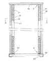
先ず、図11に於いて従来の半導体製造装置用ヒータを具備する縦型炉の概略を説明する。
【0005】
該縦型炉1は筒状のヒータ2、該ヒータ2内部に均熱管3、該均熱管3内部に反応管4が同心多重に設けられており、該反応管4にはボート5が装入される。該ボート5はボートキャップ6を介してエレベータキャップ7に載置され、該エレベータキャップ7は図示しないボートエレベータに設けられ昇降可能である。
【0006】
前記反応管4の上端にはガス導入管8が連通され、前記反応管4の下端には排気口9が設けられている。前記ガス導入管8の下端はガス供給管10と接続され、前記排気口9は排気管11と接続されている。
【0007】
前記ボート5を前記反応管4より引出した状態で、所要枚数のウェーハ12を前記ボート5に装填し、前記ボートエレベータ(図示せず)により前記ボート5を上昇させ前記反応管4内に装入する。前記ヒータ2で前記反応管4内を所定の温度に加熱し、前記ガス供給管10、ガス導入管8より反応ガスを前記反応管4内に導入し、前記ウェーハ12表面に薄膜を生成し、反応後のガスは前記排気口9、排気管11を経て排気される。
【0008】
次に、図11〜図15に於いて前記ヒータ2について説明する。
【0009】
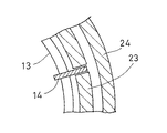
前記均熱管3の周りを囲む様にコイル状の発熱線13が設けられ、該発熱線13は断面が円形で、保持用ピース14により円周を所要等分した位置で支持されている。
【0010】
該保持用ピース14はハイアルミナ(アルミナ94.2%含有)製で、鉛直方向に多数個連結されている。
【0011】
前記各保持用ピース14の上面15には2個の外側斜め上方に延出する突起部16,17が形成され、該突起部16の肉厚は前記突起部17の肉厚より厚く、前記突起部16の外側側面が前記上面15と成す内角と前記突起部17の外側側面が前記上面15と成す内角とは等しくなっている。前記2個の突起部16,17の間には半円柱形状の上向凹曲面18が形成され、該上向凹曲面18の直径は前記発熱線13の直径より若干大きくしてある。又、前記保持用ピース14の下面には凹部19が設けられ、該凹部19は逆台形状の嵌合部20と、該嵌合部20に連続して形成された下向き半円形の下向凹曲面21とで形成され、前記嵌合部20は前記突起部16,17と嵌合可能となっている。前記突起部16,17と前記嵌合部20が嵌合することにより、前記各保持用ピース14間の鉛直方向及び前記縦型炉1の径方向の相対変位は規制されると共に前記上向凹曲面18と前記下向凹曲面21とで円形断面の空洞部22を形成する様になっている。
【0012】
更に、多数の前記保持用ピース14が鉛直方向に連結されることで、鉛直方向に等間隔で多数の前記空洞部22が形成され、該空洞部22内に前記発熱線13が挿通され支持される。
【0013】
該発熱線13の外周囲には2重に断熱材23,24が巻設され、内側の断熱材23は前記保持用ピース14の一端部を円周方向から挾持している。更に、前記断熱材24の外面は図示しないヒータケースにより覆われている。
【0014】
前記縦型炉1内で前記ウェーハ12に成膜処理中、前記発熱線13が発熱し膨脹することにより、前記発熱線13のコイル直径が拡大し、前記保持用ピース14には前記縦型炉1の反中心方向に力が作用し、該保持用ピース14は前記発熱線13と共に前記縦型炉1の反中心方向に移動する。又、前記断熱材23も前記発熱線13の発熱の影響で高温となり膨脹する。
【0015】
成膜処理完了後、前記発熱線13が発熱を停止すると、該発熱線13の温度が降下し、コイルの直径が収縮することにより前記保持用ピース14には前記縦型炉1の中心方向の力が作用し、該保持用ピース14は前記発熱線13と共に前記縦型炉1の中心方向に移動する。又、前記断熱材23も前記発熱線13の温度降下の影響で温度が降下し収縮する。
【0016】
前記縦型炉1内で前記ウェーハ12に成膜処理が施される度に、前記縦型炉1内は昇温、降温を繰返し、前記発熱線13、断熱材23は前述した様に膨脹、収縮を繰返す。
【0017】
【発明が解決しようとする課題】
上記した従来のヒータでは各保持用ピース間の円周方向の相対変位は保持用ピースの構造上規制されていないので、炉内の昇温、降温が繰返されることにより、発熱線、断熱材が膨脹、収縮を繰返し、保持用ピースが前記断熱材より抜脱し、更に前記保持用ピース間で円周方向の相対変位が生じて、各保持用ピース間の連結が外れ、発熱線同士が接触し短絡事故が発生する虞れがある。
【0018】
又、発熱線の拡大、収縮により発熱線が保持用ピースと共に縦型炉の径方向に移動し、発熱線が導電性のある均熱管と接触し、漏電事故が発生する虞れがある。
【0019】
更に、搬送時等に外部から衝撃が加わると、連結された保持用ピースの縦型炉の中心方向及び反中心方向の動きが規制されていない為、連結された状態で保持用ピースが縦型炉の中心方向に移動すると、断熱材による保持用ピースの支持が外れる。更に、各保持用ピース間の円周方向の相対変位が構造上規制されていない為、各保持用ピース間の連結が円周方向にずれたり外れることがあった。更に又、各保持用ピース間の連結が外れた衝撃等により保持用ピース等が破損することもあり、部品の取替えや再組立てが必要となり不経済であった。
【0020】
本発明は斯かる実情に鑑み、保持用ピースのずれ、外れ、破損等を防止し、耐久性、安全性及び経済性の向上が図れる半導体製造装置用ヒータを提供しようとするものである。
【0021】
【課題を解決するための手段】
本発明は、被加熱体の周りにコイル状に成形された発熱線が配設され、鉛直方向に多数連設された保持用ピース間に径方向に長い長円の空洞部が形成され、前記発熱線が前記空洞部を挿通し、前記保持用ピースを介して支持されたヒータ支持装置に係り、又、前記保持用ピースの上面と下面の少なくともどちらか一方に凹部を設けると共に他方に該凹部に嵌合可能な突起部を設け、前記凹部、突起部をそれぞれ左右非対称としたヒータ支持装置に係り、又、前記保持用ピースが鉛直方向に連設されたピースホルダに水平方向の動きが規制される様支持され、該ピースホルダが前記発熱線の周りに設けられた周囲断熱材に支持されたヒータ支持装置に係り、又、前記保持用ピースと前記ピースホルダの少なくともどちらか一方に凹部を設けると共に該凹部側面に係止溝を形成し、他方に該係止溝に係合可能な係止凸部を形成し、前記保持用ピースが前記ピースホルダに前記係止溝を介して嵌脱可能としたヒータ支持装置に係り、又、前記ピースホルダの上端面と下端面の少なくともどちらか一方に凹部を設け、他方に該凹部に嵌合可能な凸部を設けたヒータ支持装置に係り、更に又、前記周囲断熱材、ヒータがヒータコイル受けに立設され、前記周囲断熱材の上端に設けられた天井断熱材の下面に下方に突出する段差部を設け、前記ヒータコイル受け上面に隆起部を設け、前記最上位のピースホルダが前記最上位の保持用ピースより突出し、前記最下位のピースホルダが前記最下位の保持用ピースより突出し、前記最上位のピースホルダ突出部が前記段差部に係合可能とし、前記最下位のピースホルダ突出部が前記隆起部に係合可能としたヒータ支持装置に係り、前記発熱線の発熱により前記被加熱体を加熱すると共に前記発熱線が温度変化により膨脹、収縮し、前記空洞部内を前記被加熱体の径方向に移動する。又、前記保持用ピースは前記ピースホルダに水平方向の動きを規制され、該ピースホルダは前記段差部及び前記隆起部により中心方向の動きを規制されると共に前記周囲断熱材により反中心方向及び円周方向の動きを規制される。
【0022】
【発明の実施の形態】
以下、図1〜図10に於いて本発明の実施の形態を説明する。
【0023】
被加熱体である図示しない均熱管と同心にコイル状の発熱線31が設けられ、該発熱線31は断面が円形で、連結された保持用ピース32により円周を所要等分した位置で支持されている。
【0024】
該保持用ピース32はハイアルミナ(アルミナ96%含有)製で、鉛直方向に多数個連結されている。
【0025】
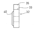
前記各保持用ピース32の上面33には上方が左右離反方向に延出する2個の突起部34,35が形成され、前記突起部34の外側側面が前記上面33と成す内角aは前記突起部35の外側側面が前記上面33と成す内角bより小さくなっている。前記2個の突起部34,35の間には断面が半長円形の上向凹曲面36が形成されている。又、前記保持用ピース32の下面には凹部37が設けられ、該凹部37は逆台形状で前記突起部34,35と嵌合可能な嵌合部38と、該嵌合部38に連続して設けられた半長円形の下向凹曲面39とで形成されている。又、保持用ピース32の反中心側の一側面には鉛直方向に延びる略半円柱形状の係止凸部40が形成されている。
【0026】
前記突起部34,35と前記嵌合部38が嵌合することにより、前記各保持用ピース32間の鉛直方向及び縦型炉(図示せず)の径方向の相対変位は規制され、又、前記上向凹曲面36と前記下向凹曲面39とで縦型炉の径方向に長い長円形状の空洞部41を形成する様になっている。前記保持用ピース32が鉛直方向に多数連結されることで、鉛直方向に等間隔で多数の前記空洞部41が形成される。
【0027】
前記連結された保持用ピース32の最上位置には前記上向凹曲面36と後述する段差部54で挾持された最上位の空洞部41aが形成され、最下位置には前記保持用ピース32の前記嵌合部38に前記突起部34,35と前記上向凹曲面36を有する最下位用保持用ピース42が嵌合することにより最下位の空洞部41bが形成されている。前記発熱線31は非発熱時の最も収縮した状態で前記空洞部41の中心側に位置し、前記空洞部41の前記縦型炉の反中心側に空隙を保つ様、前記空洞部41に挿通され支持される。
【0028】
前記保持用ピース32の前記縦型炉の反中心側はピースホルダ43に嵌合されている。該ピースホルダ43は縦長の直方体に鉛直方向に貫通する凹部44を刻設し形成され、水平断面が略コの字状を成し、該凹部44の一内側面には半円柱状の係止溝45が刻設されている。
【0029】
前記ピースホルダ43の上端面46には前記凹部44の縁に沿って凸部47が形成され、該凸部47の外周縁部はテーパ面となっている。又、前記ピースホルダ43の下端面48には前記凹部44の縁に沿って凹部49が形成され、前記凸部47は前記凹部49と契合可能となっている。而して、前記凸部47と前記凹部49との契合により、前記各ピースホルダ43間の水平方向の相対変位が規制される様になっている。
【0030】
前記ピースホルダ43は継目が前記保持用ピース32の継目と一致しない様、鉛直方向に連結され、前記保持用ピース32の前記縦型炉の反中心側は前記凹部44に嵌合可能であり、前記係止溝45に前記係止凸部40が嵌合することにより、前記保持用ピース32の前記ピースホルダ43に対する前記縦型炉の径方向及び円周方向の相対変位が規制される様になっている。
【0031】
該ピースホルダ43の周囲には前記発熱線31と同心に円筒形状の周囲断熱材50,51が2重に設けられている。該周囲断熱材50には円周を所要等分した各位置に該周囲断熱材50の上端から下端に亘り鉛直方向にそれぞれ溝52が刻設され、該溝52に前記ピースホルダ43が反中心方向側及び円周方向側の3側面を当接させ支持されている。連結された前記ピースホルダ43の最上位置には最上位用ピースホルダ43aが連結され、最下位置には最下位用ピースホルダ43bが連結され、連結された前記ピースホルダ43の高さは前記周囲断熱材50の高さと同一となっている。更に、前記周囲断熱材51の外面は図示しないヒータケースにより覆われている。
【0032】
連結された前記ピースホルダ43及び前記周囲断熱材50,51の上端には円盤形状の天井断熱材53が水平姿勢で設けられている。該天井断熱材53の下面には該天井断熱材53より一回り小さい円盤形状の段差部54が下方に突出し、該段差部54の外周縁に前記最上位用ピースホルダ43aの中心側側面の上部が当接する様になっている。該段差部54は最上位の前記発熱線31の上端が略当接する厚さになっている。
【0033】
前記ピースホルダ43及び前記周囲断熱材50,51は断熱シート55を介して円環状のヒータコイル受け56に立設され、該ヒータコイル受け56上面には内周縁に沿って、前記最下位用ピースホルダ43bの中心側側面の下部が当接する隆起部57が形成されている。該隆起部57の外周縁は前記段差部54の外周縁と同心且同径の円形を成し、前記隆起部57の上に前記断熱シート55を介して前記最下位用保持用ピース42が支持されている。又、前記ヒータコイル受け56の外周面及び下面にはそれぞれ前記断熱シート55が貼設されている。
【0034】
而して、前記最上位用ピースホルダ43aの中心側側面の上部が前記段差部54の外周縁に当接し、更に、前記最下位用保持用ピース42が前記隆起部57上に支持される分、前記ピースホルダ43が下方に突出し、突出した部分が前記隆起部57に当接し、前記ピースホルダ43の中心方向への動きは規制される。
【0035】
以下作動を説明する。尚、従来と同等のものについては説明を省略する。
【0036】
前記縦型炉(図示せず)内でウェーハに成膜処理が行われている間、前記縦型炉内は前記発熱線31により加熱され該発熱線31自体も高温となる。該発熱線31は膨脹し、コイル径が拡大し、前記保持用ピース32に支持されている部分を含め全周に亘り前記縦型炉の反中心方向に移動する。前記空洞部41は前記縦型炉の反中心側に空隙を残置している為、前記発熱線31の前記空洞部41での反中心方向の移動を許容し前記保持用ピース32に力が作用することがなく、又、連結された前記ピースホルダ43の反中心方向側側面は前記断熱材50により支持されているので、連結された前記ピースホルダ43が前記縦型炉の反中心方向に移動することはない。又、前記断熱材50は前記発熱線31の発熱により高温となり膨脹する。
【0037】
成膜処理完了後、前記発熱線31は発熱を停止し、該発熱線31自体の温度が降下する。該発熱線31のコイル径は縮小し、全周に亘り前記縦型炉の中心方向に移動する。前記発熱線31は最も収縮した状態で前記空洞部41の中心側に位置する様予め設定されている為、前記発熱線31のコイル径の縮小により、連結された前記保持用ピース32に中心方向に力が作用することがなく、又、連結された前記ピースホルダ43の最上部及び最下部がそれぞれ前記段差部54及び前記突起部57に当接している為、連結された前記ピースホルダ43が前記縦型炉の中心方向に移動することはない。前記断熱材50は温度降下につれて収縮するが、前記発熱線31のコイル径の縮小により前記ピースホルダ43の移動を引起すことはない。
【0038】
尚、上記実施の形態に於いては、前記保持用ピース32の上面33に前記突起部34,35が設けられ、下面に前記凹部37が形成されているが、前記上面33に前記凹部37が設けられ、下面に前記突起部34,35が設けられていてもよく、又、両面に突起部及び凹部がそれぞれ嵌合可能に設けられていてもよい。又、前記ピースホルダ43の下面に前記凸部47が設けられ、上面に前記凹部49が設けられていてもよく、又、両面に凸部及び凹部がそれぞれ嵌合可能に設けられていてもよい。更に、前記保持用ピース32は鉛直方向に所定の間隔で連結されているが、外側部分に前記発熱線31挿通用の切欠部を設ける等該発熱線31の挿通手段を考慮し、連結間隔をより長くしてもよく、又、一体型としてもよい。又、前記ピースホルダ43の連結間隔も長くしてもよく、又、一体型としてもよい。更に又、前記凹部44は前記保持用ピース32と前記ピースホルダ43とが嵌合可能で且前記保持用ピース32の動きが規制されれば、他の形状でもよく、どちらか一方或は両方に凹部と凸部がそれぞれ嵌合可能に設けられていてもよく、更に、前記保持用ピース32とピースホルダ43は一体であってもよい。
【0039】
更に上記実施の形態は半導体製造装置に実施した場合であるが、半導体製造装置以外の炉を有する装置に実施可能であることは言う迄もない。
【0040】
【発明の効果】
以上述べた如く本発明によれば、発熱線は保持用ピースに相対移動可能に支持されている為、発熱線のコイル径の拡大、縮小により連結されている保持用ピースに力が作用することがなく、又、保持用ピースはピースホルダに対して、縦型炉の径方向及び円周方向の相対変位が規制され、更に、連結されているピースホルダの縦型炉の中心方向の動きは天井断熱材の段差部及びヒータコイル受けの隆起部により規制されている。従って、発熱線の膨脹、収縮により保持用ピースの連結等が外れ、部品が破損したり、発熱線同士が接触して短絡を起したり、又、発熱線が導電性のある他の部品と接触し、漏電事故が発生するのを防止でき、耐久性、安全性の向上が図れる。又、搬送時等に保持用ピースの連結等が外れ、部品が破損することがないので再組立作業を要することがない。更に、保持用ピースの凹部及び突起部の形状が左右対称でないので間違って左右逆に組立てることがなく作業性、生産性及び経済性の向上が図れる。更に又、保持用ピース及びピースホルダをそれぞれ複数個連結させることで、発熱線の膨脹、収縮により水平方向の力が保持用ピース及びピースホルダに作用しても連結部分に力を吸収するだけの逃げを作ることができる為、保持用ピースの破損や発熱線の折損を防止することができる等種々の優れた効果を発揮する。
【図面の簡単な説明】
【図1】本発明の実施の形態を示す断面図である。
【図2】図1のA−A矢視図である。
【図3】図2のB部拡大図である。
【図4】該実施の形態に於ける保持用ピースの正面図である。
【図5】該保持用ピースの平面図である。
【図6】該保持用ピースの側面図である。
【図7】該実施の形態に於けるピースホルダの側面図である。
【図8】該ピースホルダの平面図である。
【図9】図1のC部拡大図である。
【図10】図1のD部拡大図である。
【図11】従来の縦型炉を示す断面図である。
【図12】図11のE部拡大図である。
【図13】従来例に於ける保持用ピースの取付け状態を示す部分詳細図である。
【図14】従来例に於ける保持用ピースの正面図である。
【図15】該保持用ピースの平面図である。
【符号の説明】
31 発熱線
32 保持用ピース
41 空洞部
43 ピースホルダ
50 周囲断熱材
51 周囲断熱材
53 天井断熱材
54 段差部
56 ヒータコイル受け
57 隆起部[0001]
BACKGROUND OF THE INVENTION
The present invention relates to a semiconductor manufacturing apparatus and a semiconductor device manufacturing method , and more particularly to an improvement in a semiconductor manufacturing apparatus heater used in a vertical furnace.
[0002]
[Prior art]
One of the semiconductor manufacturing processes is a diffusion or chemical vapor deposition process, and a vertical furnace is an apparatus for performing such a process.
[0003]
The vertical furnace supplies a reaction gas while heating the inside of the furnace to generate various thin films on the surface of a substrate to be processed such as a wafer, and includes a heater as a heating device.
[0004]
First, referring to FIG. 11, an outline of a vertical furnace provided with a conventional heater for a semiconductor manufacturing apparatus will be described.
[0005]
The
[0006]
A
[0007]
With the
[0008]
Next, the
[0009]
A coiled
[0010]
The
[0011]
On the
[0012]
Further, a large number of the
[0013]
Insulating
[0014]
During the film forming process on the
[0015]
When the
[0016]
Each time the
[0017]
[Problems to be solved by the invention]
In the conventional heater described above, the relative displacement in the circumferential direction between the holding pieces is not restricted due to the structure of the holding pieces, so that the heating wire and the heat insulating material are formed by repeating heating and cooling in the furnace. Repeated expansion and contraction, the holding piece is pulled out of the heat insulating material, and the relative displacement in the circumferential direction occurs between the holding pieces, the connection between the holding pieces is disconnected, and the heating wires come into contact with each other. There is a risk of a short circuit accident.
[0018]
In addition, due to the expansion and contraction of the heating wire, the heating wire moves in the radial direction of the vertical furnace together with the holding piece, and the heating wire may come into contact with the conductive soaking tube, which may cause a leakage accident.
[0019]
Furthermore, when an impact is applied from the outside during transport, etc., the movement of the connected holding pieces in the center direction and the anti-center direction of the vertical furnace is not restricted, so the holding pieces are connected in the vertical state. When moving toward the center of the furnace, the support of the holding piece by the heat insulating material is released. Furthermore, since the relative displacement in the circumferential direction between the holding pieces is not structurally restricted, the connection between the holding pieces may be displaced or disengaged in the circumferential direction. Furthermore, the holding pieces and the like may be damaged due to an impact or the like in which the connection between the holding pieces is disconnected, which is uneconomical because replacement or reassembly of parts is required.
[0020]
In view of such circumstances, the present invention aims to provide a heater for a semiconductor manufacturing apparatus that can prevent the holding piece from being displaced, detached, damaged, and the like, and can improve durability, safety, and economy.
[0021]
[Means for Solving the Problems]
In the present invention, a heating wire formed in a coil shape is disposed around the object to be heated, and a long oval cavity is formed in the radial direction between a plurality of holding pieces arranged in a vertical direction. A heating wire is inserted into the cavity and is related to a heater support device supported via the holding piece. A recess is provided on at least one of the upper surface and the lower surface of the holding piece, and the recess is provided on the other side. Providing a protrusion that can be fitted to the heater, and the recess and protrusion are asymmetrical to the heater support device, and the horizontal movement is restricted by the piece holder in which the holding pieces are connected in the vertical direction. The piece holder is supported by a surrounding heat insulating material provided around the heating wire, and a recess is provided in at least one of the holding piece and the piece holder. If provided A locking groove is formed on the side surface of the recess, and a locking projection that can be engaged with the locking groove is formed on the other side. The holding piece can be fitted into and removed from the piece holder via the locking groove. And a heater support device provided with a concave portion on at least one of the upper end surface and the lower end surface of the piece holder, and provided with a convex portion that can be fitted into the concave portion on the other, and In addition, the surrounding heat insulating material and the heater are erected on the heater coil receiver, a stepped portion protruding downward is provided on the lower surface of the ceiling heat insulating material provided on the upper end of the peripheral heat insulating material, and a raised portion is formed on the upper surface of the heater coil receiving member The uppermost piece holder protrudes from the uppermost holding piece, the lowermost piece holder protrudes from the lowermost holding piece, and the uppermost piece holder protruding portion forms the stepped portion. Engageable, the bottom The piece holder projecting portion of the heater is engageable with the raised portion, and the heated body is heated by the heat generated by the heating wire, and the heating wire expands and contracts due to a temperature change. Is moved in the radial direction of the heated body. Further, the holding piece is restricted in movement in the horizontal direction by the piece holder, and the piece holder is restricted in movement in the center direction by the stepped portion and the raised portion, and is anti-centered and circular by the surrounding heat insulating material. Circumferential movement is restricted.
[0022]
DETAILED DESCRIPTION OF THE INVENTION
Hereinafter, an embodiment of the present invention will be described with reference to FIGS.
[0023]
A
[0024]
The holding
[0025]
Two
[0026]
By fitting the
[0027]
An uppermost hollow portion 41a sandwiched between the upward concave
[0028]
An opposite center side of the vertical furnace of the holding
[0029]
A
[0030]
The
[0031]
Around the
[0032]
A disk-shaped ceiling
[0033]
The
[0034]
Thus, the upper portion of the central side surface of the
[0035]
The operation will be described below. In addition, description is abbreviate | omitted about the thing equivalent to the former.
[0036]
While the film formation process is performed on the wafer in the vertical furnace (not shown), the vertical furnace is heated by the
[0037]
After the film forming process is completed, the
[0038]
In the above embodiment, the
[0039]
Furthermore, although the said embodiment is a case where it implements in a semiconductor manufacturing apparatus, it cannot be overemphasized that it can implement in the apparatus which has furnaces other than a semiconductor manufacturing apparatus.
[0040]
【The invention's effect】
As described above, according to the present invention, since the heating wire is supported by the holding piece so as to be relatively movable, a force acts on the holding piece connected by expanding or reducing the coil diameter of the heating wire. In addition, relative displacement of the holding piece with respect to the piece holder in the radial direction and the circumferential direction of the vertical furnace is restricted, and the movement of the connected piece holder in the center direction of the vertical furnace is It is regulated by the step portion of the ceiling heat insulating material and the raised portion of the heater coil receiver. Therefore, due to expansion and contraction of the heating wire, the connection of the holding pieces, etc., is broken, the parts are damaged, the heating wires come into contact with each other to cause a short circuit, and the heating wire is connected with other conductive parts. Contact can be prevented from causing a leakage accident, and durability and safety can be improved. Further, since the holding pieces are not disconnected during the transportation or the like and the parts are not damaged, reassembly work is not required. Further, since the shape of the concave portion and the protruding portion of the holding piece is not symmetric, it is possible to improve workability, productivity and economy without erroneously assembling the left and right sides. Furthermore, by connecting a plurality of holding pieces and piece holders, even if a horizontal force acts on the holding piece and piece holder due to expansion and contraction of the heating wire, the force is absorbed only by the connecting portion. Since relief can be made, various excellent effects such as prevention of breakage of the holding piece and breakage of the heating wire are exhibited.
[Brief description of the drawings]
FIG. 1 is a cross-sectional view showing an embodiment of the present invention.
FIG. 2 is a view taken in the direction of arrows AA in FIG.
FIG. 3 is an enlarged view of a portion B in FIG. 2;
FIG. 4 is a front view of a holding piece in the embodiment.
FIG. 5 is a plan view of the holding piece.
FIG. 6 is a side view of the holding piece.
FIG. 7 is a side view of the piece holder in the embodiment.
FIG. 8 is a plan view of the piece holder.
FIG. 9 is an enlarged view of part C in FIG. 1;
10 is an enlarged view of a part D in FIG. 1. FIG.
FIG. 11 is a cross-sectional view showing a conventional vertical furnace.
12 is an enlarged view of a portion E in FIG.
FIG. 13 is a partial detail view showing a mounting state of a holding piece in a conventional example.
FIG. 14 is a front view of a holding piece in a conventional example.
FIG. 15 is a plan view of the holding piece.
[Explanation of symbols]
31
Claims (4)
Priority Applications (1)
| Application Number | Priority Date | Filing Date | Title |
|---|---|---|---|
| JP23884997A JP3848442B2 (en) | 1997-08-20 | 1997-08-20 | HEATER SUPPORT DEVICE, SEMICONDUCTOR MANUFACTURING DEVICE, AND SEMICONDUCTOR DEVICE MANUFACTURING METHOD |
Applications Claiming Priority (1)
| Application Number | Priority Date | Filing Date | Title |
|---|---|---|---|
| JP23884997A JP3848442B2 (en) | 1997-08-20 | 1997-08-20 | HEATER SUPPORT DEVICE, SEMICONDUCTOR MANUFACTURING DEVICE, AND SEMICONDUCTOR DEVICE MANUFACTURING METHOD |
Related Child Applications (1)
| Application Number | Title | Priority Date | Filing Date |
|---|---|---|---|
| JP2006104351A Division JP4145328B2 (en) | 2006-04-05 | 2006-04-05 | Heater support device, heating device, semiconductor manufacturing device, and semiconductor device manufacturing method |
Publications (2)
| Publication Number | Publication Date |
|---|---|
| JPH1167424A JPH1167424A (en) | 1999-03-09 |
| JP3848442B2 true JP3848442B2 (en) | 2006-11-22 |
Family
ID=17036185
Family Applications (1)
| Application Number | Title | Priority Date | Filing Date |
|---|---|---|---|
| JP23884997A Expired - Lifetime JP3848442B2 (en) | 1997-08-20 | 1997-08-20 | HEATER SUPPORT DEVICE, SEMICONDUCTOR MANUFACTURING DEVICE, AND SEMICONDUCTOR DEVICE MANUFACTURING METHOD |
Country Status (1)
| Country | Link |
|---|---|
| JP (1) | JP3848442B2 (en) |
Families Citing this family (7)
| Publication number | Priority date | Publication date | Assignee | Title |
|---|---|---|---|---|
| KR100643661B1 (en) | 2005-04-11 | 2006-11-10 | (주)비에이치티 | Heater assembly of heat treatment equipment and fabrication method thereof |
| JP5049128B2 (en) | 2005-08-24 | 2012-10-17 | 株式会社日立国際電気 | SUBSTRATE PROCESSING APPARATUS, HEATING DEVICE USED FOR THE SAME, SEMICONDUCTOR MANUFACTURING METHOD USING THE SAME, AND HEAT GENERATION HOLDING STRUCTURE |
| KR100808766B1 (en) | 2007-01-09 | 2008-02-29 | 홍진혁 | Ceramic insulator and cylindrical electric furnace |
| JP5114449B2 (en) * | 2009-03-31 | 2013-01-09 | 株式会社ハナガタ | Heat tunnel heating device |
| JP5787563B2 (en) * | 2010-05-11 | 2015-09-30 | 株式会社日立国際電気 | Heater support device, heating device, substrate processing device, semiconductor device manufacturing method, substrate manufacturing method, and holding piece |
| JP5565188B2 (en) * | 2010-08-10 | 2014-08-06 | 東京エレクトロン株式会社 | Heater device |
| EP3937688A2 (en) * | 2019-03-11 | 2022-01-19 | Nicoventures Trading Limited | Aerosol provision device |
Family Cites Families (7)
| Publication number | Priority date | Publication date | Assignee | Title |
|---|---|---|---|---|
| JPS5623675Y2 (en) * | 1977-03-16 | 1981-06-03 | ||
| JPH0110921Y2 (en) * | 1984-11-05 | 1989-03-29 | ||
| JPH047598Y2 (en) * | 1987-03-16 | 1992-02-27 | ||
| JPH086237Y2 (en) * | 1990-03-13 | 1996-02-21 | 株式会社リケン | Heater holder for vertical annular furnace |
| JPH079036Y2 (en) * | 1990-11-13 | 1995-03-06 | 東京エレクトロン東北株式会社 | Vertical heat treatment furnace |
| US5506389A (en) * | 1993-11-10 | 1996-04-09 | Tokyo Electron Kabushiki Kaisha | Thermal processing furnace and fabrication method thereof |
| JPH0963963A (en) * | 1995-08-23 | 1997-03-07 | Hitachi Ltd | Semiconductor substrate treating device and treatment of semiconductor substrate |
-
1997
- 1997-08-20 JP JP23884997A patent/JP3848442B2/en not_active Expired - Lifetime
Also Published As
| Publication number | Publication date |
|---|---|
| JPH1167424A (en) | 1999-03-09 |
Similar Documents
| Publication | Publication Date | Title |
|---|---|---|
| TWI425584B (en) | Thermal processing furnace | |
| KR100530407B1 (en) | Apparatus for fabricating a semiconductor device | |
| JPH079036Y2 (en) | Vertical heat treatment furnace | |
| JP5787563B2 (en) | Heater support device, heating device, substrate processing device, semiconductor device manufacturing method, substrate manufacturing method, and holding piece | |
| US5494524A (en) | Vertical heat treatment device for semiconductor | |
| KR101117016B1 (en) | Heat treatment furnace and vertical heat treatment apparatus | |
| JP3848442B2 (en) | HEATER SUPPORT DEVICE, SEMICONDUCTOR MANUFACTURING DEVICE, AND SEMICONDUCTOR DEVICE MANUFACTURING METHOD | |
| WO2007023855A1 (en) | Substrate treating device, heating device used therefor, and method of manufacturing semiconductor utilizing the devices | |
| JP4145328B2 (en) | Heater support device, heating device, semiconductor manufacturing device, and semiconductor device manufacturing method | |
| JP2000150402A (en) | Substrate supporting jig | |
| JP2006100755A (en) | Substrate processing equipment and electric heater for substrate processing equipment, and substrate processing equipment equipped with this | |
| JP5130808B2 (en) | Wafer heat treatment jig and vertical heat treatment boat equipped with the jig | |
| JPH1022227A (en) | Boat for heat treatment | |
| JP3868933B2 (en) | Atmospheric pressure CVD equipment | |
| JP3797715B2 (en) | Vertical diffusion furnace boat | |
| JP2001176811A (en) | Wafer support device | |
| JP4590162B2 (en) | Substrate holder, laminated boat, semiconductor manufacturing apparatus and semiconductor device manufacturing method | |
| JPH10209253A (en) | Substrate supporting device | |
| JP2006108677A (en) | Semiconductor manufacturing machine | |
| JPH08107079A (en) | Vertical wafer boat and vertical heat treatment furnace | |
| JP5524782B2 (en) | Heater unit and semiconductor wafer manufacturing method | |
| JP5304068B2 (en) | Vertical heat treatment equipment | |
| JP3777964B2 (en) | Substrate support for heat treatment | |
| US20110146578A1 (en) | Substrate processing apparatus | |
| JP2008258280A (en) | Heating apparatus |
Legal Events
| Date | Code | Title | Description |
|---|---|---|---|
| A521 | Written amendment |
Free format text: JAPANESE INTERMEDIATE CODE: A523 Effective date: 20040324 |
|
| A621 | Written request for application examination |
Free format text: JAPANESE INTERMEDIATE CODE: A621 Effective date: 20040324 |
|
| A977 | Report on retrieval |
Free format text: JAPANESE INTERMEDIATE CODE: A971007 Effective date: 20060209 |
|
| A131 | Notification of reasons for refusal |
Free format text: JAPANESE INTERMEDIATE CODE: A131 Effective date: 20060228 |
|
| A521 | Written amendment |
Free format text: JAPANESE INTERMEDIATE CODE: A523 Effective date: 20060427 |
|
| TRDD | Decision of grant or rejection written | ||
| A01 | Written decision to grant a patent or to grant a registration (utility model) |
Free format text: JAPANESE INTERMEDIATE CODE: A01 Effective date: 20060808 |
|
| A61 | First payment of annual fees (during grant procedure) |
Free format text: JAPANESE INTERMEDIATE CODE: A61 Effective date: 20060825 |
|
| R150 | Certificate of patent or registration of utility model |
Free format text: JAPANESE INTERMEDIATE CODE: R150 |
|
| FPAY | Renewal fee payment (event date is renewal date of database) |
Free format text: PAYMENT UNTIL: 20100901 Year of fee payment: 4 |
|
| FPAY | Renewal fee payment (event date is renewal date of database) |
Free format text: PAYMENT UNTIL: 20110901 Year of fee payment: 5 |
|
| FPAY | Renewal fee payment (event date is renewal date of database) |
Free format text: PAYMENT UNTIL: 20120901 Year of fee payment: 6 |
|
| FPAY | Renewal fee payment (event date is renewal date of database) |
Free format text: PAYMENT UNTIL: 20130901 Year of fee payment: 7 |
|
| FPAY | Renewal fee payment (event date is renewal date of database) |
Free format text: PAYMENT UNTIL: 20140901 Year of fee payment: 8 |
|
| EXPY | Cancellation because of completion of term |