JP3845018B2 - Method for transmitting high-speed data stream, especially multimedia data stream, over internet-type network between server and chip card terminal - Google Patents
Method for transmitting high-speed data stream, especially multimedia data stream, over internet-type network between server and chip card terminal Download PDFInfo
- Publication number
- JP3845018B2 JP3845018B2 JP2001557760A JP2001557760A JP3845018B2 JP 3845018 B2 JP3845018 B2 JP 3845018B2 JP 2001557760 A JP2001557760 A JP 2001557760A JP 2001557760 A JP2001557760 A JP 2001557760A JP 3845018 B2 JP3845018 B2 JP 3845018B2
- Authority
- JP
- Japan
- Prior art keywords
- data
- agent
- type
- intelligent
- session
- Prior art date
- Legal status (The legal status is an assumption and is not a legal conclusion. Google has not performed a legal analysis and makes no representation as to the accuracy of the status listed.)
- Expired - Fee Related
Links
Images


Classifications
-
- H—ELECTRICITY
- H04—ELECTRIC COMMUNICATION TECHNIQUE
- H04L—TRANSMISSION OF DIGITAL INFORMATION, e.g. TELEGRAPHIC COMMUNICATION
- H04L63/00—Network architectures or network communication protocols for network security
- H04L63/04—Network architectures or network communication protocols for network security for providing a confidential data exchange among entities communicating through data packet networks
- H04L63/0428—Network architectures or network communication protocols for network security for providing a confidential data exchange among entities communicating through data packet networks wherein the data content is protected, e.g. by encrypting or encapsulating the payload
- H04L63/0442—Network architectures or network communication protocols for network security for providing a confidential data exchange among entities communicating through data packet networks wherein the data content is protected, e.g. by encrypting or encapsulating the payload wherein the sending and receiving network entities apply asymmetric encryption, i.e. different keys for encryption and decryption
-
- G—PHYSICS
- G06—COMPUTING; CALCULATING OR COUNTING
- G06F—ELECTRIC DIGITAL DATA PROCESSING
- G06F16/00—Information retrieval; Database structures therefor; File system structures therefor
- G06F16/90—Details of database functions independent of the retrieved data types
- G06F16/95—Retrieval from the web
- G06F16/957—Browsing optimisation, e.g. caching or content distillation
-
- H—ELECTRICITY
- H04—ELECTRIC COMMUNICATION TECHNIQUE
- H04L—TRANSMISSION OF DIGITAL INFORMATION, e.g. TELEGRAPHIC COMMUNICATION
- H04L63/00—Network architectures or network communication protocols for network security
- H04L63/08—Network architectures or network communication protocols for network security for authentication of entities
- H04L63/0853—Network architectures or network communication protocols for network security for authentication of entities using an additional device, e.g. smartcard, SIM or a different communication terminal
-
- H—ELECTRICITY
- H04—ELECTRIC COMMUNICATION TECHNIQUE
- H04L—TRANSMISSION OF DIGITAL INFORMATION, e.g. TELEGRAPHIC COMMUNICATION
- H04L63/00—Network architectures or network communication protocols for network security
- H04L63/16—Implementing security features at a particular protocol layer
- H04L63/166—Implementing security features at a particular protocol layer at the transport layer
-
- H—ELECTRICITY
- H04—ELECTRIC COMMUNICATION TECHNIQUE
- H04L—TRANSMISSION OF DIGITAL INFORMATION, e.g. TELEGRAPHIC COMMUNICATION
- H04L67/00—Network arrangements or protocols for supporting network services or applications
- H04L67/01—Protocols
- H04L67/02—Protocols based on web technology, e.g. hypertext transfer protocol [HTTP]
-
- H—ELECTRICITY
- H04—ELECTRIC COMMUNICATION TECHNIQUE
- H04L—TRANSMISSION OF DIGITAL INFORMATION, e.g. TELEGRAPHIC COMMUNICATION
- H04L69/00—Network arrangements, protocols or services independent of the application payload and not provided for in the other groups of this subclass
- H04L69/30—Definitions, standards or architectural aspects of layered protocol stacks
- H04L69/32—Architecture of open systems interconnection [OSI] 7-layer type protocol stacks, e.g. the interfaces between the data link level and the physical level
- H04L69/322—Intralayer communication protocols among peer entities or protocol data unit [PDU] definitions
- H04L69/326—Intralayer communication protocols among peer entities or protocol data unit [PDU] definitions in the transport layer [OSI layer 4]
-
- H—ELECTRICITY
- H04—ELECTRIC COMMUNICATION TECHNIQUE
- H04L—TRANSMISSION OF DIGITAL INFORMATION, e.g. TELEGRAPHIC COMMUNICATION
- H04L9/00—Cryptographic mechanisms or cryptographic arrangements for secret or secure communications; Network security protocols
- H04L9/40—Network security protocols
-
- H—ELECTRICITY
- H04—ELECTRIC COMMUNICATION TECHNIQUE
- H04L—TRANSMISSION OF DIGITAL INFORMATION, e.g. TELEGRAPHIC COMMUNICATION
- H04L69/00—Network arrangements, protocols or services independent of the application payload and not provided for in the other groups of this subclass
- H04L69/12—Protocol engines
-
- H—ELECTRICITY
- H04—ELECTRIC COMMUNICATION TECHNIQUE
- H04L—TRANSMISSION OF DIGITAL INFORMATION, e.g. TELEGRAPHIC COMMUNICATION
- H04L69/00—Network arrangements, protocols or services independent of the application payload and not provided for in the other groups of this subclass
- H04L69/30—Definitions, standards or architectural aspects of layered protocol stacks
- H04L69/32—Architecture of open systems interconnection [OSI] 7-layer type protocol stacks, e.g. the interfaces between the data link level and the physical level
Abstract
Description
【0001】
本発明は、サーバとチップカード端末との間のインターネット型ネットワーク上での高速データストリームに関する。
【0002】
より詳細には、本発明は、セキュア化マルチメディアデータストリームの送信方法に関する。
【0003】
本発明の枠組においては、「高データレート」という用語は、データレートが毎秒100kビット程度またはそれ以上であるデータストリームに関する。たとえば、「MP3」符号化データの音声ファイルは、このファイルがデジタル回線を通じてリアルタイムで送信される場合には、1分間すなわちおよそ100kビット/秒の録音について1MBの記憶空間を必要とする。また、リアルタイムで表示するためにおよそ2Mビット/秒程度の送信速度を必要とするビデオデータストリームを挙げることもできる。ましてや、画像、ビデオおよび/または音声を同時に伝搬することができるいわゆるマルチメディアデータストリームもこれに該当する。
【0004】
同じく本発明の枠組においては、「チップカード端末」という用語は一般的な意味において理解されなければならない。この端末はとくに、WINDOWSまたはUNIX(両者とも登録商標である)など種々のオペレーティングシステム上で動作するパソコンで構成することができる。端末はまた、ワークステーションまたはノート型パソコンで構成することもできる。
【0005】
同様に、本発明の枠組においては、「インターネット網」という用語は、本来の意味でのインターネット網の他、「イントラネット」と呼ばれる種類の企業私有網または同様な網、「エクストラネット」と呼ばれる種類の外部に伸展する網、およびより一般的には、インターネット型プロトコルによりデータのやりとりが行われるあらゆる網も含む。
【0006】
趣旨を明らかにするために、以下の記述においては、別に記載がある場合は別として、たとえばセキュア化マルチメディアデータストリームの送信など、本発明の範囲から逸脱することなく、本発明の好ましい応用の場合を想定することにする。
【0007】
「セキュア化」とは、機密性を確保するか、少なくとも自由にデータにアクセスできないようにするために、当該データの全部または一部が暗号化されることを意味する。後者の目的の場合、有料アクセスデータを指すこともある。いずれにせよ、所望するデータ(たとえばマルチメディアファイル)を取得するためのトランザクションが可能な識別データ(パスワード、識別子すなわち「ログイン」、クレジットカード番号等)を入力することが通常必要である。これらのデータはいわゆる「影響を受け易く」、インターネット網上では「平文」で送信することができない。したがってこれらのデータはセキュア化、すなわち暗号化またはたとえば「SSL」(Secure Socket Layerの略)型のセキュア化プロトコルの使用を行わなければならない。
【0008】
インターネット網のめざましい発展にともない、この網を介して種々のサーバおよび/またはクライアントシステムから/またはへ、あらゆる種類のデジタルファイルを送信することが可能であることという第1の必要性が生じた。これらの2つのシステムを接続する伝送路またはこの伝送路の一部分の通過帯域が小さい時でも(たとえば、V90規格を実施する時、およそ56kビット/秒を限度とする交換型電話回線が該当する)、この伝送路を介して大きなファイルを送信することはたしかに可能であるが、大部分の場合、ダウンロードが終了した後に非リアルタイムでしかこのファイルを使用することができない。高速通信路(ケーブルまたは衛星による接続のサービス統合デジタル網「RNIS」すなわち英語の用語による「ISDN」)が利用可能であることにより、インターネット網に接続された端末による音声ファイルさらにはマルチメディアファイルのリアルタイム送信を考えることが可能である。通常の電話回線ですら、「ADSL」という略号で知られている最近の送信技術を利用する時には、1Mビット/秒程度の速度でデジタルデータを送信することが可能である。
【0009】
ところで、歴史的に見ると、インターネット網に接続されたリモートサーバと端末との間の伝送路が「ボトルネック」となっていた。したがって鎖の両端の情報システム、すなわちサーバおよび端末、マルチメディアファイルの送信および/または処理、および配信に必要なデータレートを受け入れることができることは明らかである。最近、インターネット網上に高速路が設置されたことにより、この種の「エンドツーエンド」処理が可能である。
【0010】
顕著になっている別の需要は端末と組み合わせるチップカードの使用である。
【0011】
実際、チップカードを基本とするアプリケーションシステムにおいては、チップカードには、種々の機能、特にセキュリティ機能が割り当てられる。セキュリティに関するデータ(パスワード、アクセス権など)は、ユーザが保存できるチップカード内に格納することが有利である。またデータは、暗号化が可能な形態で固定メモリ内に記録されることから、容易に変更することができず、外部から直接読むこともできない。
【0012】
有料トランザクションの枠組においては同様の機能が使われる。上で喚起したように、パスワードおよび/または識別子、ならびに種々のセンシブルデータ(クレジットカードの番号など)、およびユーザの権利(現在有効な購読、アクセス可能なサービスなど)を画定するデータを送信することも必要である。
【0013】
しかしながら、知られている技術においては、受信および/または送信されたデータストリームがチップカードを通過しないため、チップカードの内部に「セキュリティ機能」を直接実現することはできないことに留意されたい。したがって、セキュリティに関するチェックが行われるようにするためには、端末とチップカードとの間に対話が確立されなければならない。この動作モードはセキュリティレベルを低下させ、さらには、ある悪条件下では、端末内に「トロイの木馬」を呼び込んでしまうことがある。
【0014】
したがって、セキュリティチェックは、原位置すなわちチップカードそのものの中で行われることが必要であり、そのため、データストリームは、端末に送信される前にチップカードにバイパスされることが必要となろう。
【0015】
チップカードは、自身に割り当てられた「セキュリティ」機能に加え、端末内で行われるいくつかの動作を直接管理することができるとともに、たとえば、端末により受信および/または送信されるデータのあらかじめ決められた特性を変更することができることも有利である。
【0016】
知られている技術においては、以下に示すように、これらの動作モードは、現在利用可能な技術およびチップカードを基本とするアプリケーションのために選定された規格には適合しない。
【0017】
まず、図1Aおよび図1Bを参照して、チップカードを基本とするアプリケーションシステムの一般的なアーキテクチャを簡単に振り返ることにする。
【0018】
チップカードを基本とするアプリケーションシステムは、主要な要素として、通常
− チップカード
− 前出の端末を構成するホストシステム
− 好ましいアプリケーション内のインターネット網などの通信ネットワーク
− インターネット網に接続されたアプリケーションサーバ
を含む。
【0019】
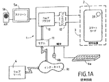
図1Aは、この種のアーキテクチャの例の略図である。たとえばパソコンである端末1は、チップカード2のリーダ3を含む。このリーダ3は、物理的に端末1内に組み込むことも組み込まないようにすることも可能である。チップカード2は、入出力接続部が、電気エネルギの供給および端末1の通信を可能にするように、その支持部の表面と同じ高さになる集積回路20を含む。端末は、インターネット網RIへのアクセス回路11を備える。この回路は、交換電話回線、あるいは本発明の場合には、好ましくは、より高速な通信路すなわちケーブルまたは衛星による接続のサービス統合デジタル網(「RNIS」)に接続するためのモデムで構成することができる。回路11により、直接、あるいはインターネットサービス接続業者(英語の用語による「インターネットサービスプロバイダ」または「ISP」)を経由して、インターネット網RIに接続することが可能である。また、「プロキシ」、あるいは「ファイヤウォール」と呼ばれる隔離システム(「防火壁」、さらには「見張番」とも呼ばれる)などの中間システムに頼ることも可能である。
【0020】
当然のことながら、端末1は、CPU、RAMおよびROM、磁気ディスク大容量メモリ、ディスクおよび/またはCD−ROMドライブなど、図を簡略化する目的から図示しなかったが、その動作に必要な全ての回路および装置を備える。
【0021】
通常、端末1は、表示スクリーン5aおよび(本発明の枠組においてはマルチメディアファイルの配信が可能な)音声再生システム5b、キーボード6aおよびマウス6bなど、内蔵または非内蔵の通常の周辺装置にも接続される。
【0022】
端末1は、網RIに接続されたサーバまたは全ての情報処理システムと通信状態に入ることができるが、図1Aには、そのうちの1つのシステムのみを図示してある。アクセス回路11は、「WEB」ナビゲータ、あるいは英語の用語では「ブラウザ」と呼ばれる特殊ソフトウェア10により、端末1とサーバ4とを通信状態にする。通常、「クライアント−サーバ」モードにより網RIの全体に分散した種々のデータアプリケーションまたはファイル、特にマルチメディアファイルには、ナビゲータによりアクセスすることができる。
【0023】
通常、ネットワーク上の通信は、複数の重畳ソフトウェア層を備える規格を満たすプロトコルに従って行われる。インターネット型網RIの場合、以下に詳述するが、通信は、同じく複数のソフトウェア層を備えるこの種の通信に特有なプロトコルに従って行われる。通信プロトコルは、より個別的に求められるアプリケーション、すなわち「WEB」ページの問い合せ、フィアルの転送、電子メール(E−mel、あるいは英語の用語による「e−mail」)、フォーラム、または「ニュース」など、に応じて選択される。
【0024】
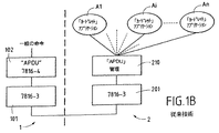
図1Bに、端末と、チップカードリーダと、チップカードとを備えるシステムの論理アーキテクチャの略図を示す。このアーキテクチャは規格ISOにより記述されおり、同規格そのものも複数の部分集合、すなわち、
− カードの寸法およびマーキングに関するISO7816−1および7816−2
− 端末とチップカードとの間のデータ転送に関するISO7816−3
− 命令セットおよびコマンドのフォーマットに関するISO7816−4
図1Bの端末1側には、符号101の規格ISO7816−3に準拠する層、および符号102の「APDU」命令マネージャ(規格ISO7816−4)のみを示した。チップカード2側においては、規格ISO7816−3に準拠する層には符号201を付し、「APDU」命令マネージャ(規格ISO7816−4)には符号210を付した。アプリケーションには符号A1、...、Aj、...、Anを付したが、ここでnはチップカード2上に存在するアプリケーションの最大数である。
【0025】
チップカード2(図1A)内に存在する「cardlet」アプリケーションは、命令セットにより端末1と対話する。通常、このセットは書き込み命令と読み出し命令とを有する。命令のフォーマットは、「APDU」(「Application Protocol Data Unitの意)という英語の略語で知られている。この書式は前出の規格ISO7816−4により規定されている。コマンドの「APDU」は「APDU.command」と記され、応答の「APDU」は「APDU.response」と記される。「APDU」は、前出の規格ISO7816−3により規定されたプロトコル(たとえばキャラクタモード:T=0、またはブロックモード:T−1)により、カードリーダとチップカードとの間でやりとりされる。
【0026】
図1Bに示すように、チップカード2が異なる複数のアプリケーションを含む時、マルチアプリケーティブカードと呼ぶ。しかしながら、端末1は一度に1つのアプリケーションとしか対話しない。アプリケーションAjは、たとえば、「JAVA」言語(登録商標)による「アプレット」と呼ばれるソフトウェアの形態を成し、以下、これを「カードレット」と呼ぶ。個別の「カードレット」Ajの選択は選択型「APDU」(「SELECT」)により得られる。いったんこの選択が行われると、これに続く複数の「APDU」がこの「カードレット」に向けて送られる。新規の「APDU SELECT」は、現在実行中のアプリケーションを破棄し、別のアプリケーションを選択する作用を有する。「APDU」210のマネージャソフトウェアサブセットにより、チップカード2内で個別のアプリケーションAjを選択すること、このようにして選択されたアプリケーションを記憶すること、およびこのアプリケーションへの「APDU」の送信および/またはそこからの受信が可能である。
【0027】
上で記述してきたことを要約すると、アプリケーションAjの選択およびアプリケーションとの対話は「APDU」命令のやりとりにより行われる。アプリケーションAjは従来のアプリケーションであり、以後、「GCA」(「Generic Card Application」すなわち一般カードアプリケーションの意)と呼ぶことにする。
【0028】
以上の点を思い起した上で、スマートカード2は、市販の標準ブラウザのコードを変更しない限り、そうしたブラウザとは直接対話できない点に留意されたい。
【0029】
さらに、また特に、そもそも上述の標準および規格に合致している現在のスマートカードは、同じくインターネットRIと直接通信できないハードウェアおよびソフトウェアの構成を有する。とりわけ、それらは、この型のネットワークで使用されるプロトコルのいずれかに従って、データパケットを受取り、伝達することができない。したがって、一般には、英語で「プラグイン」で呼ばれるものの形で、端末内1に設置される追加ソフトウェアを備えることが必要である。図2Aでは参照番号12が付されているこのソフトウェアは、ブラウザ10とカード2との、より厳密にはこのカード2の電子回路20との間のインターフェイスを実施する。
【0030】
諸技術の過去の急速な発展およびその予想される将来の進化を考慮に入れたとしても、チップカードのRAMまたはROM回路への情報記録容量は、この容量をこのチップカードの「ホスト」端末が提供する容量、および当然のことながら、「ミニコンピュータ」またはいわゆる「メインフレーム」型の大型システムといった、より大型のシステムが提供する容量と比較すると、依然として限界があり将来においても限界があることは明らかである。また、大きなデータのファイル、特にマルチメディア型ファイルをチップカード内に保存することは不可能である。したがって、チップカードをインターネット網と通信させること、およびそこにデータを通過させることが可能であること(上で示してきたように、知られている技術では不可能である)を認めながら、「一斉」に、すなわちたとえ一時的であってもメモリに記憶することなく、全ての処理を行うことが必要であろう。知られている技術または短期的に実現可能な技術の現状においては、チップカード内に存在する論理回路、特にマイクロプロセッサの計算能力ではこのような動作モードを実現することができない。
【0031】
最後に、前出の規格は、シリアル型リーダを介してチップカードと端末との間の通信を編成する。その上、現在の技術により可能なデータレートは1〜10kビット/秒程度と非常に低く、そのことは、ここでもまた、本発明のアプリケーションの一環として想定するデータレート(最低でも100kビット/秒)に適合しない。
【0032】
本発明は、顕著になってき需要、すなわち、特に、最大のセキュリティを享受しつつ高データレートストリームに対応することができるようにするという需要を満たしつつ、上でそのいくつかについて喚起してきた、知られている技術の方法および装置の欠点を解消することを目的とする。
【0033】
本発明の第1の特徴によれば、チップカードは、自身に結合されている端末のための「WEB」型サーバ/クライアントの役割を果たす。
【0034】
これを行うために、端末内のチップカードおよびその垂下部に専用通信ソフトウエア層を設ける。「専用」という用語は本発明の方法に対し専用であると理解されたい。事実、これらの専用通信層は、想定するアプリケーションの如何に関わらず、両方向性のものである。これら層は、チップカードと端末との間、ならびにチップカードとネットワークとの間の双方向のデータのやりとりのプロセスにおいてのみ動作する。
【0035】
専用通信ソフトウェア層は、特にプロトコルの変換が可能な「インテリジェントエージェント」と呼ばれるソフトウェアコンポーネントを特に含む。以後、インテリジェントエージェントを単に「エージェント」と呼ぶことにする。それぞれ端末およびチップカードに結合された専用通信層内に設置されるエージェントが存在する。本発明の方法によれば、設置されたエージェント間でセッションが確立される。
【0036】
これらの構成により、リーダを介したチップカードと端末との間の端末のための前出のISO規格をみたしつつ、チップカードでデータストリームの全部または一部をインターネット網からまたはインターネット網側にバイパスすることが可能になる。
【0037】
本発明の別の特徴によれば、チップカード内に、以後の文書では「フィルタ」と呼ぶことにする特別アプリケーションをインプリメントする。これには、「プロキシ」の役割と同様の役割を果たすソフトウェアエンティティが関わる。これを行うために、エージェントを利用する前出の構成を用いる。この「プロキシ」により、セキュリティに関するデータの処理を、チップカードの内部で直接実施することが可能になる。
【0038】
本発明の別の特徴によれば、非対称通信プロトコルをインプリメントする。この特徴によれば、送信中または受信中のデータストリームは2つのコンポーネント、すなわち直接チップカードを通過し、少ないデータ量を示す低データレート第1ストリーム −以後「クリティカルデータストリーム」と呼ぶ−と、端末を通過し、多いデータ量を示す高データレート第2ストリーム −以後「オパークデータストリーム」と呼ぶ−とに分割される。
【0039】
本発明の好ましい適用においては、クリティカルデータストリームは、チップカードの前出の「プロキシ」において機密的に処理されるよう、このプロキシに送ることができるセキュリティデータで構成される。オパークデータは本来の意味でのマルチメディアデータで構成される。これらのデータは端末内にあるエージェントにより処理される。しかしながら、オパークデータの受信および処理の許可は、チップカード内のセキュリティデータにより開始される認証手順の結果に依存する。前出のフィルタが存在するため、端末によるデータの受信はチップカードの直接制御下にある。
【0040】
端末を通過するオパークデータは、チップカードの制御および管理の下、実際の使用の前、すなわちチップカードが受信したクリティカルデータの画定後、端末内で個別の処理を受けることもできる。
【0041】
これを行うために、チップカードと端末との間、またはこれらの装置の一方のみの内部に配置された追加特別エージェントを設け、これを「プロトコルの」追加特別エージェントと呼ぶ。
【0042】
したがって本発明は、少なくとも1つのリモートサーバと、チップカードリーダを具備する端末との間における、インターネット型ネットワークを経由するデータストリームの送信方法であって、前記端末が少なくとも1つの「TCP/IPクライアント」型アプリケーションを含み、前記端末と前記サーバの双方が前記インターネット型ネットワークに接続され、
a/前記チップカード内に、専用通信プロトコル層を形成する第1ソフトウェアをインプリメントすることから成る第1段階と、
b/前記端末内に、専用通信プロトコル層を形成し、少なくとも1つの前記「TCP/IPクライアント」型アプリケーションとのインタフェースを形成する第2ソフトウェアをインプリメントすることから成る第2段階と
を備えること、
− さらに前記第1および第2ソフトウェアがそれぞれ、少なくとも1つのクライアント型の第1独立ソフトウェアエンティティと、サーバ型の第2独立ソフトウェアエンティティとを備え、前記端末と前記チップカード(との間で双方向データ交換セッションを確立し、前記チップカードが「WEB」型クライアント/サーバの機能を提供するようにし、かつ前記インターネット型網を経由して、前記端末と、前記リモートサーバとの間で双方向データ交換セッションを確立するよう、端末およびチップカードの情報処理手段により前記エンティティが、協働し、前記独立ソフトウェアエンティティが、あらかじめ決められたプロトコルのデータユニットで通信すること、
− 前記第2専用ソフトウェア部内に含まれるクライアントおよびサーバ型の前記第1および第2独立ソフトウェアエンティティにおよび/またはからプロトコルデータユニットを受信および/または送信する「フィルタ」と呼ばれる所与の機能特性の適用ソフトウェアを前記チップカード内に実施する段階を備え、前記適用部分の実施が前記サーバ型独立ソフトウェアエンティティの制御下にあること、
− 前記専用第1ソフトウェアの前記独立ソフトウェアエンティティとのセッションを開始し、前記端末と前記リモートサーバとの間で送信される前記データストリームのあらかじめ決められた特性を変更するために、前記フィルタが、前記専用第2ソフトウェアの前記独立ソフトウェアエンティティと協働すること
を特徴とする方法を主な対象とする。
【0043】
次に、添付の地面を参照してより詳細に本発明を記述する。
【0044】
以下の記述においては、別に記載がある場合、すなわち、WEBサーバも接続されるインターネットサーバに接続された端末と協働するチップカード上にインプリメントされたプロキシによりセキュア化されたマルチメディアデータストリームの場合は別として、本発明の範囲から逸脱することなく、本発明の好ましい応用の場合を想定することにする。
【0045】
本発明によるチップカード内に位置するアプリケーションの起動手順を記述し、図2を参照してその実施のためのアーキテクチャについて詳細に説明する前に、まず、ネットワーク上の通信プロトコルの主な特徴を振り返ってみることが有益であろう。
【0046】
通信ネットワークのアーキテクチャは種々の層により記述される。たとえば「ISO」が規定する「OSI」規格(「Open System Interconnection」)は、下位層(物理的な送信媒体に関する「物理層」)から、特に「トランスポート層」をはじめとする中間層を経て、上位層(たとえば「アプリケーション層」)まで7つの層を含む。ある所与の層は、適当なインタフェースを介して、1つ上位の層にサービスを提供し、1つ下位の層に対し他のサービスを要求する。層はプリミティブを使用して通信する。層は同レベルの層と通信することもできる。アーキテクチャによっては複数の層が欠けていることもある。
【0047】
インターネット型環境においては層数は5つ、すなわちより正確には、上位から下位に向かって、アプリケーション層(「http」、「ftp」、「e−mail」など)、トランスポート層(「TCP」)、ネットワークアドレシング層(「IP」)、データリンク層(「PPP」、「Slip」など)、および物理層である。
【0048】
端末1およびスマートカード2a内にそれぞれ設置された、参照番号13および23aの特有の通信プロトコルソフトウェア層を例外として他のハードウェアまたはソフトウェアエレメントは、従来の技術に共通するため、ここで再び詳細に説明する必要はない。
【0049】
端末1は、たとえばモデムで構成されたネットワークRIへのアクセス回路11を有する。これら回路は、「物理」層と「データリンク」層に対応する、下層ソフトウェア、C1およびC2を包括する。
【0050】
また、「ネットワークアドレシング」層(インターネットの場合には「IP」)と「トランスポート」層(「TCP」)に対応する、上層、C3およびC4が示されている。アプリケーション上層(「http」、「ftp」、「eメール」等)は示されていない。
【0051】
下層、C1およびC2と上層、C3およびC4との間のインターフェースは、一般に「下層ドライバ」と呼ばれるソフトウェア層によって構成される。上層、C3およびC4は、このインターフェイス上に支持され、それらに対応する特有の機能のライブラリまたはネットワークライブラリ14を介して利用される。インターネットの場合には、「TCP/IP」は、「ソケット」と呼ばれるライブラリを用い利用される。
【0052】
こうした構造から、ブラウザ10は、ファイル転送用または電子郵便の送信用の「WEB」ページ(「HTTP」プロトコル)の閲覧のために、サーバ4に向かって要求を出すことが可能であり、それはまったく従来の方法で行われる。
【0053】
端末1はまた、一体型または非一体型のカード読取装置3を有する。スマートカード2aと通信するために、カード読取装置30はまた、層C1およびC2と類似の役割を果たす、2つの低層、CC1(物理層)とCC2(データリンク層)を包括する。層CC1およびCC2とのソフトウェアインターフェイスは、たとえば、仕様「PC/SC」(「第6部、サービスプロバイダ」)によって説明される。層自体、CC1およびCC2は、特に、上述したように、規格ISO 7816−1から7816−4によって説明される。
【0054】
補足的ソフトウェア層16は、応用層(ここには図示されていない)と下層、CC1およびCC2との間でインターフェイスを形成する。この層16に割り当てられる主要機能は、マルチプレキシング/デマルチプレキシング機能である。
【0055】
スマートカード2aとの通信は、「UNIX」型オペレーティングシステム、すなわちOUVRIR(「OPEN」)、LIRE(「READ」)、ECRIRE(「WRITE」)、FERMER(「CLOSE」)等におけるファイルの操作のために使用されるものと類似のパラダイムに従って行われる。
【0056】
スマートカード2a側には、類似の構造、すなわち参照番号CCa1(物理層)およびCCa2(データリンク層)が付された2つの低層の存在、さらには層16とまったく同じインターフェイス層26aが見られる。
【0057】
本発明の第1の特徴によれば、両側に、すなわち端末1およびスマートカード2aにおいて、特有の2つのプロトコル層、つまり、それぞれ13および23aが備えられる。
【0058】
端末1においては、特有の層13は、マルチプレキシング層16を介して、「ドライバ低層」15、ネットワーク層C3およびC4のライブラリ14、さらに、カード読取装置3のプロトコル層、すなわち下層CC1およびCC2とインターフェイスしている。特有の層13は、スマートカード2aから、またスマートカード2aに向かって、ネットワークパケットの転送を可能にする、さらに、この層は、スマートカード2aを利用する用途に、インターネットブラウザ10や電子郵便等のような既存のアプリケーションを適合させる。
【0059】
スマートカード2a側には、層13と対をなして、参照番号23aが付された特有の層の補足的インスタンスで構成されたまったく同様の構造が見られる。
【0060】
より厳密には、特有の層13および23aは、以下の3つの主要なソフトウェアエレメントに細分割される。
【0061】
−従来の層CC1、CC2、CCa1およびCCa2を介する、層13と23aの間の情報ブロックの転送モジュール130または230a、
−たとえば、プロトコルの変換機能を実行する「インテリジェントエージェント」132または232aと呼ばれる1つまたは複数のソフトウェア、
−個別のインテリジェントエージェントと同一視することができるモジュールである、特有の構成の管理モジュール、131および231a。
【0062】
以下、簡略化するために、先述したように、インテリジェントエージェントを「エージェント」と呼ぶ。
【0063】
したがって、端末1とスマートカード2a内に、2つのエンティティ間の通信プロトコルスタックが見られる。
【0064】
レベル2の層(データリンク層)CC2およびCCa2は、スマートカード2aと端末1との間の交換を行う。それらの層は、伝送エラーの検出と、場合によっては補正を行う。種々のプロトコルが使用可能であり、以下は限定的ではなく、あくまで例示的なものである。
【0065】
−勧告ETSI GSM11.11、
−キャラクタモードT=0における、規格ISO 7816−3によって規定されたプロトコル、
−ブロックモードT=1における、規格ISO 7816−3によって規定されたプロトコル、または
−フレームモード「HDLC」(「High−Level Data Link Control procedure」の略)において、規格ISO 3309によって規定されるプロトコル。
【0066】
本発明の枠組みにおいては、好ましくは、ブロックモードにおけるプロトコルISO 7816−3が使用される。
【0067】
それ自体良く知られている方法で、各プロトコル層に対して、同レベルの層間、さらに層から層へのデータの交換を可能にする一定数のプリミティブが関連付けられる。例として、レベル2の層に関連付けられるプリミティブは、カードによる「データ要求(「Data.request」)および「データの確認」(「Data.confirm」)等の型である。
【0068】
より特有の方法では、層13および23aは、スマートカード2aとホスト、すなわち端末1との間の対話を担当する。それらの層は、たとえば、「HTML」フォーマットにおけるハイパーテキストの形で実行されるメニュを介して、端末1のユーザ(図示せず)とスマートカード2aとの間の情報交換を可能にする。それらはまた、データパケットの送信および/または受信のために適合した構成の設置を可能にする。
【0069】
上述したように、層は3つの別々のエンティティを有する。
【0070】
第一の層130または230aは、主に、ソフトウェアマルチプレクサで構成される。それは、プロトコルのデータユニットの形で、スマートカード2aとホスト端末1との間の情報交換を可能にする。第一の層は、データパケットの交換器と類似の役割を果たす。それらのユニットは、レベル2の層(データリンク層)を介して送信または受信される。この通信用の個別プロトコルは、少なくとも一対のエージェントの連絡を確立させることができる。各対の第1のエージェント132は、端末1側の層13内に位置し、第2のエージェント232aは、スマートカード2a側の層23a内に位置する。2つの「エージェント」間のリンクは、「S−エージェント」と呼ぶことができるセッションに関連付けられる。セッションは、これら2つのエージェント間の双方向データ交換である。層13および23aのいずれか一方が、複数のエージェントを有する場合には、同一層のエージェントはまた、互いの間で、および/または、個別のエージェントを構成するモジュール131および231aとのセッションを確立することができる。
【0071】
より厳密には、エージェントは、端末1によって実施される構成に応じて、レベル3および4の層の機能の全体または一部を実行することができる独立ソフトウェアエンティティである。
【0072】
エージェントは、個別の特性または属性に関連付けられる。分かりやすくするために、限定的でなく例示的なものとして、以下の6つの特性がエージェントに関連付けられる。
【0073】
−「ホスト」:端末内で探索されるエージェント
−「カード」:スマートカード内で探索されるエージェント
−「ローカル」:ネットワークと通信しないエージェント
−「ネットワーク」:ネットワークと通信するエージェント(端末側)
−「クライアント」:セッションを初期化するエージェント
−「サーバ」:セッションの要求を受取るエージェント
個別のエージェントは、リファレンス、たとえば16ビットの整数によって識別される(すなわち、0から65535の間)。上位ビット(b15=1)は、リファレンスがローカルであるか(スマートカードまたは端末へのローカル通信)、または、遠隔であるか(b15=0)を示す。
【0074】
エージェントには2つの大きなカテゴリが存在する。固定リファレンスによって識別される「サーバ」型のエージェントと、構成管理モジュールによって付与される一時的と形容されることもある可変リファレンスによって識別される「クライアント」型のエージェント、131または231aである。
【0075】
エージェントは、宛先リファレンスとソースリファレンスとを構成する「プロトコルデータユニット」または「pdu」(英語「protocol data uni」の略)と呼ばれるエンティティを用いて互いに通信する。さらに、この「pdu」を、一般に使用されている英語「Smart Card」を参考にして、「SmartTP pdu」と呼ぶこともできる。「pdu」は、特に、以上に規定したリファレンスを使用する。
【0076】
「SmartTP pdu」または、以下、より簡単に「pdu」は、「pdu」の性質を明示する以下のようなフラグおよびオプションのデータを構成する、ソースリファレンス、宛先リファレンス、ビット集合を有する。
【0077】
−「OPEN」(開始)フラグは、セッション開始を示すために位置決めされる。
【0078】
−「CLOSE」(閉鎖)フラグは、セッションの閉鎖を示す。
【0079】
−「BLOCK」(鎖錠)フラグは、エージェントが、その通信相手の応答を待っている状態であり、あらゆる活動を一時停止することを示す。
【0080】
データをもたない「pdu」はトークンと呼ばれる。
【0081】
「SmartTP」エンティティは、宛先エージェントの存在をコントロールし、そのエージェントに向かってパケットの通信を実行する。
【0082】
セッションエージェント「S−Agent」は、3つの注目すべき状態を有する。すなわち、
−接続解除されている状態。いかなるセッションも他のエージェントには開始されていない。
【0083】
−接続されている状態。セッションが他のエージェントに開始されている。「S−Agent」セッションは、一対のリファレンスによって識別される。
【0084】
−ブロックされている状態。エージェントが接続され、その通信相手の応答を待つ状態。
【0085】
「S−エージェント」セッションの確立メカニズムは、以下の通りである。
【0086】
−クライアントエージェントの新しいインスタンスが創設され(スマートカードまたは端末側)、このエージェントは、擬似単一一時リファレンスによって識別される。
【0087】
−クライアントエージェントは、位置決めされた「OPEN」フラグとともにサーバエージェント(そもそも、そのリファレンスはすでに知られている)宛てに「pdu」を送信し、クライアントエージェントは、「ブロック」フラグの値に従って接続またはブロックされる状態に移行する。さらに
−サーバエージェントは、「OPEN」フラグとともに「pdu」を受け取り、接続された状態に移行する。
【0088】
いったんセッションが開始されると、2人のエージェントが「pdu」を介してデータを交換する。
【0089】
セッションの閉鎖メカニズムは以下の通りである。
【0090】
−エージェントは、場合によってはデータを有する、位置決めされたフラグ「CLOSE」とともに「pdu」を送信する。
【0091】
−他のエージェントは、(場合によってはデータを有する)位置決めされたフラグ「CLOSE」とともに「pdu」を受取り、「S−Agent」セッションは、接続解除された状態に移行する。
【0092】
図3は、上述したような「S−Agent」セッションの状態のフローチャートを概略的に表わしている。
【0093】
層130および230aは、ホスト端末1およびスマートカード2a側で、存在するエージェントリストを含む表(図示せず)を管理する。
【0094】
実際に、エージェントは、(たとえば、ハイパーテキストの)データの交換を可能にするが、しかも、ネットワークトランザクションを開始することができる。
【0095】
構成管理モジュール、それぞれ131および231aは、個別のエージェントと同一視することができる。たとえば、ホスト端末1側のモジュール131は、特に、この端末の構成(作動モード)に関連する情報、たとえば他のエージェントリスト等を管理する。スマートカード2a側のモジュール231aは、類似機能を有する。これら2つのエージェントは、セッションを確立するために互いに通信を確立することができる。
【0096】
本発明の第1の特徴によれば、チップカード2aは「WEB」クライアント/サーバとして働く。
【0097】
実際には、チップカード2aは、有利には、外部端末へのポインティングではなく端末1自身へのループバックを画定する「URL」(「Universal Resource Locater」の意味)の使用により「アドレス」される。たとえばこの「URL」の構造は以下のようになっている。
【0098】
http://127.0.0.1:8080 (1)
ここで127.0.0.1はループバックの「IP」アドレスであり、8080はポート番号である。
【0099】
図4は、図2に示す種類の本発明によるシステムのソフトウェアアーキテクチャの略図であるがより詳細に示した図である。チップカード2aは複数のエージェントを備えるが、そのうちの2つのみ、すなわち「WEB」型エージェント232a1、および非詳細画定型エージェント232a2を示した。ソフトウェアスタックは、規格ISO 7816−3(図2:CCa1およびCCa2)に対応する下位プロトコル層、符号200aと、「APDU」コマンドドライバ201a1と、パケットマルチプレクサ230aとを備え、このマルチプレクサは、エージェント、特に「WEB」エージェント232a1にインタフェースされる。
【0100】
端末1側には、2つのスタックが存在するが、一方はインターネットRIと通信し、他方はスマートカード2aと通信する。第1のスタックは、ネットワーク(規格OSI 1および2)へのアクセス機構11(図2:C1およびC2)と、参照番号100が付されたプロトコル「TCP/IP」(図3:C3およびC4)層とを有する。それらの層は「WEB」ブラウザ10とインターフェイスされる。他方のスタックは、規格ISO 7816−3に合致した参照番号101が付された下層プロトコル(図3:C1およびC2)と、命令管理「APDU」102と、パケットマルチプレクサ130とを有し、このマルチプレクサはエージェントとインターフェイスされるが、そうちの1つだけ、132がここに図示されている。このエージェントは「ネットワーク型」と想定され、さらに、一方では「TCP/IP」層101を介して、ブラウザ10と、他方では、それら「TCP/IP」層101とネットワークRIへのアクセス機構11とを介してインターネットRIと通信することができる。
【0101】
命令管理「APDU」201aはまた、単にアプリケーションと呼ばれるアプリケーションレベルの1つまたは複数の層とインターフェイスされる。それらアプリケーションA1…、Ai…、An…、は、すでに示したように、「カードレット」と呼ぶ従来型のアプリケーションである。
【0102】
要約すると、スマートカード2aによって与えられる「WEB」サーバ/クライアント機能は、すでに説明したように、スマートカード内の「WEB」エージェント232a1と、端末1内のネットワークエージェント132との関連付けによって、また、エージェント間のセッションによって実行することができる。
【0103】
したがって、スマートカード2aは「WEB」クライアント/サーバ機能を明確に表している。さらに、本発明の方法の一特徴によると、上記の「CGA」型の従来のどんなアプリケーションA1からAnも、この「WEB」クライアント/サーバを通して、端末1内に存在する「WEB」ブラウザ10によって、もしくは、エージェント間のセッションの実施によって、インターネットRIの何らかのポイントで探索された遠隔ブラウザ4によって、起動することができる。本発明の方法によれば、アプリケーションA1からAnは、書き直す必要なく、そのまま利用することができる。
【0104】
上で記述したエージェント機構を実施する本発明の別の態様によれば、チップカード2a上に「TCP/IPプロキシ」と呼ばれる機能を直接インプリメントする。この機能は、以下「フィルタ」と呼ぶことにする特別なソフトウェアアプリケーションで実施される。
【0105】
「プロキシ」機能はインターネットアプリケーションの分野においてはよく知られているが、知られている技術によるシステムのチップカード内にはインプリメントすることができない。
【0106】
本発明によるアーキテクチャを記述する前に、図5を参照して、知られている技術による従来の「プロキシ」の特徴を今一度簡潔に述べる。
【0107】
「TCP/IP」技術においては、「TCP/IP」サーバSvと「TCP/IP」クライアントClとを実現するソフトウェアエンティティPyを「プロキシ」と呼ぶ。ソフトウェアエンティティPyは、ローカルクライアントと別のリモートTCP/IPサーバとの間に接続を実現する。
【0108】
通常、プロキシPyはフィルタおよび/またはセキュリティの機能を実現する。たとえば「http」プロキシは通常、企業内において、あるナビゲータ、たとえば端末1のナビゲータ10から「WEB」サーバ4への接続を確保する(これは「ファイアウォール」すなわち「防火壁」という名称で知られている)。また、「SSL」と呼ばれるプロキシのことを指すこともある。これは、端末に対しローカルであって、インターネット網RIを通してセキュアードトンネルを確立するのに必要なセキュリティ操作(認証−機密−完全性)を実施する「プロキシ」であると定義することができる。
【0109】
次に、図6を参照して、本発明の追加的態様により「プロキシ」機能をチップカード内に直接内蔵するソフトウェアアーキテクチャを記述する。
【0110】
前の図と共通な要素には同じ符号が付与されており、これらは必要な場合にのみ再度記述する。記述を簡単にするために、端末1側のエージェントをただ1つの符号132でまとめ、チップカード2a側をただ1つの符号232aでまとめた。以下の記述では、「端末」については文字「T」で、「スマートカード(チップカード)」については「S」でこれら符号が区別される。文字は指数として数字に組み合わされる。チップカード2a上に実現される「プロキシ」27は、以下の記述においては「スマートプロキシ」と呼ぶことにする。
【0111】
「スマートプロキシ」27は、以下に記述するように、端末1側の2つ:T1およびT2、チップカード2a側の2つ:S1およびS2の4つのエージェントと、フィルタ機能28との組み合せにより実現される。すなわち、
− 「端末/クライアント/ネットワーク」エージェントT1は、(たとえばポート8080上で)TCP/IPサーバを実現する。
【0112】
− 「カード/サーバ/ローカル」エージェントS1はセッションによりエージェントT1に組み合わされ、通常、後者は「WEB」サーバの機能を実現する。
【0113】
− エージェントT1からの情報に応じて決定されるフィルタ機能28は、エージェントS1およびS2に対し「pdu」の送受信を行うことができる。
【0114】
− 「ネットワーク」エージェントT2とのセッションをオープンするフィルタ機能28およびS2により、「カード/サーバ/ローカル」エージェントS2のインスタンスが動的に生成され、S2が接続されたいと所望するインターネットリモートサーバ4のアドレスがネットワークサーバに示される。
【0115】
− 「端末/クライアント/ネットワーク」エージェントT2は、インターネットサーバ4に接続されている「TCP/IP」クライアントの機能を実現する。
【0116】
以下に、「スマートプロキシ」27の生成機構を記述する。
【0117】
以後「cTCP」と呼ぶことにし、通常、「WEB」ナビゲータ10である「TCP」クライアントは、「ネットワーク」エージェントT1との接続を開く。次にセッションT1−S1が生成される。たとえば下記URLは
http://127.0.0.1:8080/?des1=xxx.com:80/yyy/content.html (2)
エージェントT1およびS1間でセッションの開始を生じさせる。
【0118】
エージェントS1(WEBサーバ)に結合されたアプリケーションは、T1およびS1でやりとりされるデータから、どのフィルタ機能28を使用すべきかを決定する。したがって「des1」はある個別のフィルタの名称であり、「xxx.com」は、あるインターネットサーバ、たとえばサーバ4の任意の名称であり、「80」はポート番号であり、「yyy/content.html」は、例においては「HTML」言語によるページで構成される、このサーバ上の1つのファイルの任意の名称である。例においては、「des1」フィルタは、「DES」(「Data Encryption Stanard」)型アルゴリズムによる解読および/または暗号化作業を行うことができるフィルタである。
【0119】
言い換えれば、「カード」URL(2)は、外部に向けた別のURLをカプセル化し、このURLは、関係式(1)により定義されるようなループバックURLにより構成される。
【0120】
「des1」フィルタ28はクライアントS2のインスタンスを作成し、エージェントS2とT2との間でセッションが開始する。最初の「pdu」(「OPENpdu」)に挿入されるデータはインターネットサーバの名称(「xxx.com」)および結合されたポート番号(80)を指定する。
【0121】
エージェントT2は、リモートサーバ「sTCP」(「zzz.com」)に対し、「TCP」型の接続を開始する。この接続が確立するとS2に向けてトークンが送信される。
【0122】
これらのやりとりが終了すると、「スマートプロキシ」27が生成されていて、チップカード2a内に常駐するフィルタ機能28は、「ネットワーク」エージェントが受信した(インターネット網RIからの)データを処理することができる。フィルタ28は、「ネットワーク」エージェントT1およびT2により送信されたデータを論理的にチェックする。フィルタは、クライアント「cTCP」とサーバ「sTCP」との間でかわされるデータをチェックする「TCPプロキシ」として振舞う。
【0123】
趣旨を明らかにするために、種々のエージェントの任意の符号を図6に示した。すなわち、T2およびS1の「サーバ」型エージェントについての固定エージェントは「2」から「5」であり、T1およびS2の「クライアント」型エージェントについての可変または一時的エージェントは「15360」および「2559」である。
【0124】
次に、フィルタ28の個別例をより詳細に記述する。
【0125】
例1:リダイレクトフィルタ
リダイレクトフィルタは、たとえば以下のURLなどのカードURLに
(http//127.0.0.1:8080/eMail) (3)
識別データ、すなわち無料メールサーバ「email」に関連付けられたたとえば「login」およびパスワードを、よく知られている「POST http」という方法を使用することにより投稿するのに使用することができる外部サーバ(たとえばwww.email.com)への「http」要求を関連付ける。フィルタは、チャレンジを基本とするより確実な方法(これらの方法はたとえば規格「http1.1」において記述されている)。
【0126】
フィルタの実施は通常、以下の段階を含む。
【0127】
1.ナビゲータ10が「ネットワーク」エージェントT1(IPアドレス:127.0.0.1:8080)との接続を開始し、カード2aの「WEB」サーバとのセッションT1−S1が開始する
2.(勧告「http1.1rfc2068」による)「http」要求が、ナビゲータ10から「WEB」エージェントS1に送信され、このエージェントが、「/eMail」ファイルの名称から、この特別な場合におけるリダイレクトフィルタ28への呼び出しを検出し、その瞬間から、「ネットワーク」エージェントT1が受信した全データがこの特別フィルタ28により処理される
3.フィルタ28によりクライアントエージェントS2のインスタンスが生成される
4.S2が「ネットワーク」エージェントT2とのセッションを開始し、送信された最初の「pdu」(「OPEN」フラグが位置決めされる)がリモート「WEB」サーバ4のアドレスおよびポート(例においては「www.email.com」)を含む
5.エージェントT2がリモート「WEB」サーバ4との接続を開始し、開始後、トークンがエージェントS2に送信される
6.エージェントS2が「http」要求をリモート「WEB」サーバ4に送信する
7.通常、このサーバ4が、操作の成功を通知し、ナビゲータに新規接続「URL」と、使用すべきソフトウェア部「クッキー」とをナビゲータ10に供給する「http」リダイレクトヘッダを送信する
8.これらのデータに関してフィルタ機能28が何も処理を行わない
9.セッションS1−T1によりデータが「WEB」ナビゲータ10に送信される
ナビゲータ10は、リダイレクトヘッダを受信すると、適当な「クッキー」によりメールサーバ4に接続する。通常、ナビゲータは「HTML」言語で書かれたホームページを折り返し受信する。
【0128】
例2:「http−des」フィルタ
次に、前出の「DES」型アルゴリズムにより符号化される「HTML」ページの場合を想定する。たとえば「yyy/content.html」という名称のこのページは、「WEB」サーバ4、すなわち「zzz.com:80」に格納される。(任意の名称「?des1」のカード内にあるフィルタ機能28は、解読アルゴリズムすなわち逆の機能(あるいは「DES−1」)を実施するが、これには、索引1に関連付けられた鍵を使用する。
【0129】
ナビゲータ10から実行される以下のURL
http://zzz.com/yyy/content.html (4)
は、「zzz.com」サーバからの「content.html」ファイルのロードを発生させる。「HTML」ページが符号化されると、「HTML」言語の取り決めに従い文書の始まりおよび終りを示すタグ「html>および</html」は平文には現れず、ナビゲータ10は、意味のない記号か、「HTML」ページが受信されなかったことを示すエラーを表示する。
【0130】
以下のURL
http://127.0.0.1:8080/?des1=zzz.com:80/yyy/content.html (5)
は、鍵のインデックスが1である「DES」型のフィルタ28を通して以下のページをロードするようカードに指示する。
【0131】
http://zzz.com:80/yyy/content.html (6)
「content.html」ページのロードは以下の様に行われる。
【0132】
1.ナビゲータ10が「ネットワーク」エージェントT1(IPアドレス:127.0.0.1:8080)との接続を開始し、チップカード2aの「WEB」サーバとのセッションT1−S1が開始する
2.(「http1.1rfc2068」)「http」要求が、ナビゲータ10から「WEB」エージェントS1に送信され、この「WEB」エージェントS1が、「/?des1=zzz.com:80/yyy/content.html」ファイルの名称から、(索引鍵1)「DES」型フィルタ28への呼び出しを検出し、その瞬間から、「ネットワーク」エージェントT1が受信した全データが、索引鍵1に関連付けられた「DES」型フィルタ28により処理される
3.フィルタ28によりクライアントエージェントS2のインスタンスが生成される
4.S2が「ネットワーク」エージェントT2とのセッションを開始し、送信された最初の「pdu」(「OPEN」フラグが位置決めされる)がリモート「WEB」サーバ4のアドレスおよびポート(「zzz.com)を含む
5.エージェントT2がリモート「WEB」サーバ4との接続を開始し、開始後、トークンがエージェントS2に送信される
6.エージェントS2が「http」要求をリモート「WEB」サーバ4に送信する
7.リモートサーバ4が、ファイルの性質を示す「http」ヘッダを送信し、本来の意味でのファイルを送信する:これらのデータはセッションT2−S2によりフィルタ機能28に中継される
8.「http」ヘッダに関してフィルタ機能28が何も処理を行わず、「HTML」ページを解読する
9.解読されたデータが、セッションS1−T1により「WEB」ナビゲータ10に送信される
この操作の結果として、ナビゲータ10は復号された「HTML」ページを受信する。リダイレクト操作はスクリプト(通常は、登録商標である「Java Script」言語による)により自動化することができる。たとえば(仮に「content.html」)と呼ぶことにする)「HTML」ページ内に含まれるスクリプトは、以下のURL
http://127.0.0.1:8080/?des1=zzz.com/yyy/content.html (8)を
http://zzz.com/yyy/xcontent.html (7)に
リダイレクトする。
【0133】
ここでxcontent.htmlおよびcontent.htmlは2つの「HTML」の任意の名称である。
【0134】
例3:「SSL」フィルタ
「Secure Socket Layer」すなわち「SSL」と呼ばれるプロトコルは、「WEB」型アプリケーション用として広く使われている。このプロトコルにより、クライアント(通常はナビゲータ10)とサーバとの間に「セキュアトンネル」を開通させることが可能である。「SSL」により、サーバを認証するとともに、やりとりされるデータの機密性および完全性を確保することができる。これを行うために、サーバに固有の公開鍵から共有機密が作成される。共有機密からセッション鍵が推定され、この鍵により、「トリプルDES」型のアルゴリズムを使用して情報の解読が行われる。おのずとわかるように、認証「証明」を使用する技術も使用することができる。
【0135】
「SSL」フィルタをチップカード2a内に直接作製する利点は、サーバの公開鍵の証明書の確認(これが公開鍵システムの重要部分を成す)が、先験的に安全性が低いと判断される、端末内に常駐するソフトウェアではなく、チップカードにより行われることである。従来は、いったん「SSL」セッションが開かれると、ユーザすなわち「インターノート」(図示せず)は、キーボード(図1A、6a)を使用して、端末1上で平叙文で入力される「login」とパスワードとの組み合せである個人識別データを入力する。チップカード2aから実施される「SSL」セッションの別の長所は、「login」およびパスワードがユーザによってではなく、チップカード2aによって提供されることである。
【0136】
「SSL」接続は以下のようにして行われる。
【0137】
次に、「SSL」セッションにより取得を所望する「HTML」ページを想定する。たとえば「yyy/content.html」という名称のこのページは、(任意の名称「www.bank.com」)のリモート「WEB」サーバ4に格納される。(任意に「?ss1」と呼ばれる)カード内にある特別フィルタ機能28は、SSLプロトコルを実施し、login、および索引1に関連付けられたパスワードを使用する。
【0138】
以下のURL
http://127.0.0.1:8080/?ssl1=www.bank.com:80/yyy/content.html (9)
は、「SSL」プロトコルを使用して「yyy/content.html」のページをロードするようチップカード2aに指示する。
【0139】
「content.html」ページのロードは以下の様に行われる。
【0140】
1.ナビゲータ10が「ネットワーク」エージェントT1(IPアドレス:127.0.0.1:8080)との接続を開始し、チップカード2aのWEBサーバとのセッションT1−S1が開始する
2.(「http1.1rfc2068」に適合した)「http」要求が、ナビゲータ10から「WEB」エージェントS1に送信され、「WEB」エージェントS1が、「/?ss1=www.bank.com:80/yyy/content.html」ファイルの名称から、(索引鍵1を有する)「SSL」型フィルタ28への呼び出しを検出し、その瞬間から、「ネットワーク」エージェントT1が受信した全データが、索引鍵1に関連付けられた「SSL」型フィルタ28により処理される
3.フィルタ28によりクライアントエージェントS2のインスタンスが生成される
4.S2が「ネットワーク」エージェントT2とのセッションを開始し、送信された最初の「pdu」(「OPEN」フラグが位置決めされる)がリモート「SSL WEB」サーバ(「www.bank.com:443」)のアドレスおよびポート(この例においてはNo443)を含む
5.エージェントT2がリモート「WEB」サーバ4との接続を開始し、開始後、トークンがエージェントS2に送信される
6.フィルタ28がセッションT2−S2を使用して、リモートサーバ4との間で「SSL」プロトコルに準拠したネゴシエーションを開始する
7.「SSL」セッションが開始すると、フィルタ28により「login」およびパスワードがリモートサーバ4に送信され、セッションT2−S2が閉じられる
8.フィルタ28により新しいセッションS2−T2が開始される
9.フィルタ28が、前回の「SSL」セッションの再開をネゴシエートする 10.エージェントS2がファイル取得暗号化「http」要求をリモートサーバ4に送信する
11.リモートサーバ4が、ファイルの性質を示す「http」ヘッダを送信し、本来の意味でのファイルを送信する:これらのデータはセッションS2−T2によりフィルタ機能28に中継される
12.フィルタ機能28が受信データを復号しその完全性を確認する
13.解読されたデータが、セッションS1−T1により「WEB」ナビゲータ10に送信される
この操作の結果として、ナビゲータ10は復号された「HTML」ページを受信する。リダイレクト操作はスクリプト(通常は、登録商標である「Java Script」言語による)により自動化することができる。たとえば「HTML」ページ内に含まれるスクリプトは、以下のURL
http://127.0.0.1:8080/?ssl1=www.bank.com/yyy/content.html (10)を
http://www.bank.com/−yyy/xcontent.html (11)に
リダイレクトする。
【0141】
次に、非対称通信プロトコルにより特にマルチメディアデータストリームを処理することができる本発明の追加的態様を記述する。
【0142】
端末1がたとえばインターネット網RIからマルチメディアデータを取得すると、これらのデータは一切の機密的特性を失い、一般的に安全性が低いシステムにより記憶される。
【0143】
本発明の特徴のうちの1つにより実現される「スマートプロキシ」は、個別サービスの享受者の識別および認証のための鍵装置を構成する。アルゴリズムおよび鍵はチップカード2aの内部に保存され実行される。個別フィルタ28がリモートサーバ4との間で「TCP」接続をいったん開始すると、2つの場合を想定することができる。すなわち
A/データの完全性および機密性を確保するために固定鍵および秘密鍵が使用される。すなわちこの場合、「スマートプロキシ」のフィルタにより、データストリームが解読され確認される
B/フィルタ28とリモートサーバ4との間で接続の開始が成功すると、「セッション鍵」とも呼ばれる一時鍵が計算される。すなわちたとえば前出の「SSL」プロトコルまたは「IPSEC」プロトコルのようなインターネット網のために使用される多くのセキュリティプロトコルにおいては、第2のケースが発生する。
【0144】
一時セッション鍵が使用される時には、いずれにしろこれらの鍵は一回しか使われずかつ鍵の唯一の目的は安全性の低い端末へデータの平文転送を可能にすることであるため、チップカード2aによるアルゴリズムの計算には特別な意味はない。
【0145】
セキュリティの観点から見た場合、サーバ4との接続が非対称であることもある。識別手順および認証手順は秘密であるが、次にやりとりされるデータは何ら機密性を有していない。そのような経緯から、データストリームという概念が生まれることになり、以後、「スマートプロキシ」により機密的に処理すべきデータを表す「クリティカルストリーム」を「クリティカル」と呼ぶことにする。(時には同一の接続中に変化することがある)一時セッション鍵はクリティカルストリームから推定することができ、端末1は、特別な安全措置を講ずることなくこの鍵を使用することができる。
【0146】
したがってこれ以降は、「スマートプロキシ」により処理すべきデータストリームを指すクリティカルストリームと、安全ではない端末上で処理することができる「オパーク」データストリームとを区別することにする。
【0147】
この状況においては、フラグフィールドの特別な値により識別される「pdu」(コマンドの「pdu」)により、コマンドをエージェントに送信することができる。これらのコマンドは本来の意味でのアドレスされたエージェントにより処理され、別のエージェントまたはネットワークRIには送信されない。
【0148】
同じくこの状況においては、本発明に固有のエージェントの機構が実現されるが、データのやりとりはセッション外で行うことができる。
【0149】
実際、2つのエージェントは、セッションを経由して接続しなくとも、ある量のデータを交換することができる。個別コマンド「pdu」は、任意にA1と呼ぶ第1エージェントに、(ソースリファレンス、デスティネーションリファレンスおよびフラグのフィールドを除いて)送信すべきデータ量Q1を示し、別の「pdu」は、エージェントA1から送信されエージェントが受信することができるデータ量Q2を、任意にA2と呼ぶ第2エージェントに示す。「CLOSE」フラグを含む「pdu」はセッション外では送信されない。
【0150】
クリティカルおよびオパークストリームのルートはそれぞれ以下の通りである。
【0151】
クリティカルストリームは、「スマートプロキシ」に結合されたフィルタ28により処理されしたがって必ずチップカード2aを経由しなければならない機密情報を含む。オパークストリームは、たとえばセッション外データ交換機構を使用することにより、端末1上にあるエージェントによってのみ処理することができる。
【0152】
オパークストリームは、クリティカルストリームによりセキュア化することができる。
【0153】
実際、データのグローバルストリームは通常、オパークストリームとクリティカルストリームとに分解することができ、それによりたとえば、振幅がより小さいクリティカルストリームにより、(たとえば本来の意味でのマルチメディアデータを示す)高データレートストリームを解読することができる。
【0154】
本発明に固有の構成により非対称データ通信および処理プロトコルを編成することにより、そのような高データレートマルチメディアデータを処理することが可能になる。
【0155】
例4:非対称リダイレクトフィルタ
非対称リダイレクトフィルタは、
http://127.0.0.1:8080/?f1=/www.host.com/unFichier (12)
型の「カード」URLに、
http://www.host.com/unFichier (13)
のような外部サーバ4への「http」要求を関連つける。
【0156】
識別および認証の段階(たとえば「チャレンジ」を基本とする機構)を含むサーバ4への接続は、「スマートプロキシ」27に組み合わされたフィルタ28−以後任意に「?f1」と呼ぶことにする−により制御される。フィルタ28は非対称である。なぜなら、いったん認証が行われると、サーバ4との間で交換されるデータは暗号化されず、もはやフィルタ28を経由しない。
【0157】
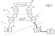
(図6のシステムの本発明によるアーキテクチャを簡略的に示す)図7の線図により概略的に示す非対称リダイレクトフィルタ28の実施段階は以下の通りである。
【0158】
1.ナビゲータ10が「ネットワーク」エージェントT1(IPアドレス:127.0.0.1:8080)との接続を開始し、チップカード2aのWEBサーバとのセッションT1−S1が開始する
2.「http」要求が、ナビゲータ10から「WEB」エージェントS1に送信され、「WEB」エージェントS1が、「/?f1=/www.host.com/unFichier」ファイルの名称から、個別リダイレクトフィルタ28(「?f1」)への呼び出しを検出し、その瞬間から、「ネットワーク」エージェントT1が受信した全データがこのフィルタ28により処理される
3.フィルタ28によりクライアントエージェントS2のインスタンスが生成される
4.S2が「ネットワーク」エージェントT2とのセッションを開始し、送信された最初の「pdu」(「OPEN」フラグが位置決めされる)がリモート「WEB」サーバ4のアドレスおよびポート(「www.host.com」)を含む
5.エージェントT2がリモート「WEB」サーバ4との接続を開始し、開始後、トークンがエージェントS2に送信される
6.フィルタ28(「?f1」)とリモートサーバ4との間で認証手続が行われ、セッションS2−T2によりデータのやりとりが行われる
7.この手続が成功すると、フィルタ28はコマンドの「pdu」をエージェントT1に送り、エージェントT1はフィルタに対し、エージェントT2によりセッション外で送信された全データを受信することを許可し、「ネットワーク」エージェントT2にコマンドの「pdu」を送る。このエージェントはフィルタに対し、ネットワークから受信した全データをエージェントT1に送るよう指示する。すなわち、リモートサーバ4からのデータはエージェントT2およびT1によりナビゲータ10に中継されるため、チップカード2aを通過することはしなくなる
8.(サーバ4のコマンドにより)「TCP」切断が発生すると、エージェントのうちの一方T1またはT2が、「CLOSE」状態のフラグを有する「pdu」を、エージェントのうちの一方S1またはS2に送信し、フィルタ28は、セッションT1−S1およびT2−S2の放棄を管理する。
【0159】
例5:非対称「SSL」フィルタ
この例は、図6のシステムの本発明によるアーキテクチャの主要部分を簡略に示した図8の線図により概略的に図示されている。
【0160】
上の例3において記述したように、「SSL」フィルタは、「カード」URL(たとえば式(11)のそれ)を使用して能動化することができる。このようなプロトコルにおいては、解読アルゴリズムおよび単一方向ハッシュ機能(または英語で「ハッシュ」)を備える一対のエンティティ、ならびにある数の関連パラメータ(「ハッシュ」機能の鍵および現在値)を選択するために、クリティカルデータストリームが使用される。いったんネゴシエーション段階が終了すれば、チップカード2a内でのこれらのアルゴリズムの実行は特別な意味を有するものではない。なぜならデータは平文でインターネット網RIから端末1に送られるからである。
【0161】
したがって有利には、「SSL」機能が割り当てられた(サーバ型の)追加エージェントT3を使用することができる。このエージェントT3は、端末1内に配置される。いったん「SSL」セッションのパラメータのネゴシエーションが行われると、「SSL」フィルタ28は、追加クライアントエージェントS3(チップカード2a側)と「SSL」サーバエージェントT3(端末側)との間でセッションを開始する。セッションの開始時、エージェントT3は「DES」鍵の値および「ハッシュ」機能の現在のパラメータで初期化される。「SSL」フィルタ28はコマンドの「pdu」をエージェントT2に送るが、このエージェントによりフィルタは、セッション外にT3により送信されたデータをネットワークRIに再送信し、ネットワークから受信したデータをT3にリダイレクトすることができる。「SSL」フィルタ28は、エージェントT3が、T1およびT2によって送信されたデータをセッション外で受信できるようにコマンドの「pdu」をエージェントT3に送る。「SSL」フィルタはエージェントT1にコマンドの「pdu」を送るが、このエージェントによりフィルタは、セッション外にT3により送信されたデータをネットワークRIに再送信し、このネットワークRIから受信したデータをT3にリダイレクトすることができる。すると、端末1内のT1−T2−T3間にセッション外「トンネル」が確立される。エージェントT1またはT2が、自身に関連するセッションを閉じると、フィルタ28は、残っている別の2つのセッションの閉動作を行う。
【0162】
非対称フィルタ、一般的な場合
より一般的には、図7および図8の線図のいずれか1つを再度参照すると、非対称フィルタ28使用手順の諸段階は以下の通りである。
【0163】
2つのセッションT1−S1およびT2−S2により「カード」URLから「スマートプロキシ」27(図6)が作製される。作製すべき個別28がこのURLから決定される。最初にフィルタ28が、「TCP」クライアント(ナビゲータ10)とリモートサーバ4との間のデータストリームを制御する。認証およびネゴシエーション段階の終了時に一組のセキュリティパラメータが得られる。このパラメータはクリティカルデータストリームから成る。
【0164】
するとフィルタ28は、セッションの開始時にフィルタ28により定義される一組のパラメータでネゴシエーションが行われるプロトコルを実施するセキュリティエージェント(たとえばT3)とのセッションを開始する。フィルタ28は、セッションT1−T2−T3外のデータ転送「トンネル」を生成する。連T1−T2−T3により、あらかじめ決められた量のデータが帯域外で送信される。別の言い方をすれば、オパークデータストリームはT1−T2−T3のユニットで処理されるため、チップカード2aを経由しない。オパークデータは、周期的に固定されるオパークデータ長、緊急データポインタによる「TCP」パケット内のマークなど種々の方法により識別することができる。これらの方法は周知のものである。クリティカルデータはオパークデータとは反対に、端末1のエージェントT1またはT2によりフィルタ28に送信される。その結果、フィルタは、コマンドの「pdu」により、エージェントT3の機能パラメータを変更する。端末1のエージェントT1またはT2が、自身に関連するセッションを閉じると、フィルタ28は、残っている別の2つのセッションの閉動作を行う。
【0165】
同様に、一般的には、オパークデータストリームは、セキュリティに関するあらゆる態様以外に、たとえばエージェントT3と同様の追加エージェントにより実行される種々の変更を受けることができる。「セキュリティ」という用語は、特に「証明書」などを使用することにより、機密性、許可、封印、または署名などより広範な許容範囲で理解しなければならない。
【0166】
この場合、結果として、フィルタ28は上と同様に、個別の「pdu」の使用により、エージェントT3のパラメータを変更することができる。
【0167】
趣旨を明らかにするために、非限定的例として、フォーマットの変換を行うことができる。音声データの場合、たとえば「mp3」フォーマットにより符号化されて送信されるオパークデータは、「wav」フォーマット、あるいは端末1が受け入れる別のあらゆるフォーマットに変換することができる。ビデオデータについても同様であり、「MPEG」データで受信されるオパークデータは、「avi」フォーマット、あるいは端末1が受け入れる別のあらゆるフォーマットに変換することができる。
【0168】
いずれの場合も、クリティカルデータを構成する小サイズ低データレートデータストリームのみがチップカード2aを経由する。次に、T1およびT2、場合によってはT3を経由する、端末内のオパークストリームのデータの通過ならびにその処理を制御する適切なフィルタを選択するにはこれらのデータのみが必要である。
【0169】
言い換えれば、チップカードを「WEB」クライアント/サーバに変換し、この中に「プロキシ」を直接作製することができる本発明に固有な構成により、チップカードは情報ストリームの処理を委任することができるが、情報量は、チップカードが接続されている端末により固定される。きわめて高いデータレートを有するグローバルストリームは、非対称通信プロトコルが実行されるおかげで、最高の程度のセキュア化を保ちながら、チップカード端末により処理することができることがわかる。この高度なセキュア化は、主たる暗号化および/または認証作業がチップカードの排他的制御下にあり、クリティカルデータがチップカードを経由することによるものである。
【0170】
前出の内容を読むことにより、本発明は設定した目的を達成したことが容易に確認できよう。
【0171】
しかしながら、本発明は、特に図2から図4ならびに図6から図8を参照して明示的に記述した実施例に限定されるものではないことは明らかであろう。
【0172】
また、記述した過程は反転可能であること、すなわちサーバと端末との間の送信は双方向に行うことができることも明らかであろう。実際、端末は、常にチップカードの制御下で、高データレートファイルをリモートサーバに送信することもできる。この場合、クリティカルデータは、万一、リモートサーバとのネゴシエーション段階があった場合にはその後に、チップカードに供給される。
【0173】
最後に、高データレートセキュア化マルチメディアデータストリームの送信の場合における方法を詳細に記述したが、上に示したような本発明による方法は、この個別の適用例に何ら限定されるものではない。
【0174】
本発明は、少なくとも1つのリモートサーバと、チップカードリーダを具備する端末との間における、インターネット型ネットワークを経由するデータストリームの送信方法であって、前記端末が情報処理手段と情報記憶手段とを備え、情報記憶手段が少なくとも1つの「TCP/IPクライアント」型アプリケーションを含み、チップカードが情報処理手段と情報記憶手段とを備え、前記端末と前記サーバの双方が前記インターネット型ネットワークに接続され、
a/前記チップカード(2a)の情報記憶手段内に、専用通信プロトコル層を形成する第1ソフトウェア(23a)をインプリメントすることから成る第1段階と、
b/前記端末(1)の情報記憶手段内に、専用通信プロトコル層を形成し、少なくとも1つの前記「TCP/IP」型アプリケーション(10)とのインタフェースを形成する第2ソフトウェア(13)をインプリメントすることから成る第2段階と
を備えること、
− さらに前記第1および第2ソフトウェア部(13、23a)がそれぞれ、クライアント型の第1独立ソフトウェアエンティティ(T2、S1)と、サーバ型の第2独立ソフトウェアエンティティ(T1、S2)とを備え、前記端末(1)と前記チップカード(2a)との間で双方向データ交換セッションを確立し、前記チップカード(2a)が「WEB」型クライアント/サーバの機能を提供するようにし、かつ前記インターネット型網(RI)を経由して、前記端末(1)と、前記リモートサーバ(4)との間で双方向データ交換セッションを確立するよう、端末およびチップカードの情報処理手段により前記エンティティ(T1、S1、T2、S2)が、協働し、前記独立ソフトウェアエンティティが、あらかじめ決められたプロトコルのデータユニットで通信すること、
− 前記第2専用ソフトウェア部(23a)内に含まれるクライアントおよびサーバ型の前記第1および第2独立ソフトウェアエンティティ(S2、S1)におよび/またはからプロトコルデータユニットを受信および/または送信する「フィルタ」(28)と呼ばれる所与の機能特性の適用ソフトウェア部を前記チップカード(2a)の情報記憶手段内に実施する段階を備え、前記適用部分の実施が前記サーバ(S1)型独立ソフトウェアエンティティの制御下にあること、
− 前記専用第1ソフトウェア部(13)の前記独立フトウェアエンティティ(T2、T1)とのセッションを開始し、前記端末(1)と前記リモートサーバ(4)との間で送信される前記データストリームのあらかじめ決められた特性を変更するために、チップカードの前記情報処理手段により、前記フィルタ(28)が、前記専用第2ソフトウェア部(23a)の前記独立ソフトウェアエンティティ(S2、S1)と協働すること
を特徴とする方法にも関する。
【図面の簡単な説明】
【図1A】 知られている技術によるチップカードを基にするアプリケーションシステムの例のそれぞれハードウェアアーキテクチャおよびソフトウェアアーキテクチャを示す略図である。
【図1B】 知られている技術によるチップカードを基にするアプリケーションシステムの例のそれぞれハードウェアアーキテクチャおよびソフトウェアアーキテクチャを示す略図である。
【図2】 本発明による、「WEB」サーバとして動作するチップカードを基にするアプリケーションシステムの例を示す略図である。
【図3】 本発明の一態様によるインテリジェントエージェントと呼ばれるソフトウェアエンタイティ間のセッションのステイタスダイアグラムである。
【図4】 チップカードがインテリジェントエージェントを備える本発明によるシステムのソフトウェアアーキテクチャの略図である。
【図5】 知られている技術による「プロキシ」の略図である。
【図6】 「プロキシ」と呼ばれるフィルタがチップカード上に作製される、図4のシステムに適合する本発明によるシステムのソフトウェアアーキテクチャの略図である。
【図7】 図6のアーキテクチャの種類の本発明によるアーキテクチャ内の(リダイレクトと呼ばれる)非対称フィルタの第1実施例を示す概略線図である。
【図8】 図6のアーキテクチャの種類の本発明によるアーキテクチャ内の(SSLと呼ばれる)非対称フィルタの第2実施例を示す概略線図である。[0001]
The present invention relates to a high-speed data stream on an Internet type network between a server and a chip card terminal.
[0002]
More particularly, the present invention relates to a method for transmitting a secured multimedia data stream.
[0003]
In the framework of the present invention, the term “high data rate” relates to a data stream having a data rate on the order of 100 kbit / s or more. For example, an audio file of “MP3” encoded data requires 1 MB of storage space for 1 minute, ie approximately 100 kbit / s recording, if this file is transmitted in real time over a digital line. Another example is a video data stream that requires a transmission rate of about 2 Mbit / sec for display in real time. This is also the case for so-called multimedia data streams that can simultaneously propagate images, video and / or audio.
[0004]
Also in the framework of the present invention, the term “chip card terminal” must be understood in a general sense. In particular, this terminal can be composed of a personal computer operating on various operating systems such as WINDOWS or UNIX (both are registered trademarks). The terminal can also consist of a workstation or a notebook computer.
[0005]
Similarly, in the framework of the present invention, the term “Internet network” refers to a type of company private network or similar network called “intranet” or “extranet” in addition to the Internet network in its original meaning. Network extending outside the network, and more generally any network in which data is exchanged by an internet type protocol.
[0006]
For the purpose of clarity, in the following description, unless otherwise stated, the preferred application of the present invention, such as the transmission of a secure multimedia data stream, without departing from the scope of the present invention. Let's assume a case.
[0007]
“Secure” means that all or part of the data is encrypted in order to ensure confidentiality or at least prevent the data from being freely accessed. For the latter purpose, it may refer to paid access data. In any case, it is usually necessary to enter identification data (password, identifier or “login”, credit card number, etc.) that can be transacted to obtain the desired data (eg, multimedia file). These data are so-called “sensitive” and cannot be transmitted in “plaintext” on the Internet. Therefore, these data must be secured, i.e. encrypted, or used for example with a secure protocol of the "SSL" (short for Secure Socket Layer) type.
[0008]
With the remarkable development of the Internet network, a first need has arisen that it is possible to send all kinds of digital files through / to various server and / or client systems. Even when the transmission line connecting these two systems or the pass band of a part of this transmission line is small (for example, when the V90 standard is implemented, a switched telephone line with a limit of about 56 kbit / s is applicable) Although it is certainly possible to send a large file via this transmission path, in most cases this file can only be used in non-real time after the download is complete. With the availability of high-speed communication channels (integrated service digital network “RNIS”, or “ISDN” in English terms) connected by cable or satellite, audio files and even multimedia files from terminals connected to the Internet network Real-time transmission can be considered. Even a normal telephone line can transmit digital data at a rate of about 1 Mbit / sec when using a recent transmission technique known by the abbreviation “ADSL”.
[0009]
By the way, historically, the transmission path between a remote server and a terminal connected to the Internet network has become a “bottleneck”. It is therefore clear that the information systems at both ends of the chain, i.e. the servers and terminals, the transmission and / or processing of multimedia files and the data rates required for delivery can be accepted. This kind of “end-to-end” processing is possible due to the recent installation of highways on the Internet network.
[0010]
Another demand that has become prominent is the use of chip cards in combination with terminals.
[0011]
In fact, in an application system based on a chip card, various functions, particularly security functions, are assigned to the chip card. Data relating to security (password, access rights, etc.) is advantageously stored in a chip card that can be stored by the user. Further, since the data is recorded in the fixed memory in a form that can be encrypted, it cannot be easily changed and cannot be directly read from the outside.
[0012]
Similar functionality is used in the paid transaction framework. Sending data defining passwords and / or identifiers and various sensitive data (such as credit card numbers) and user rights (currently valid subscriptions, accessible services, etc.), as evoked above. Is also necessary.
[0013]
However, it should be noted that in the known technology, the “security function” cannot be implemented directly inside the chip card because the received and / or transmitted data stream does not pass through the chip card. Therefore, a dialogue must be established between the terminal and the chip card in order for a security check to be performed. This mode of operation lowers the security level and, under certain adverse conditions, may lead to a “Trojan horse” in the terminal.
[0014]
Therefore, the security check needs to be done in-situ, ie in the chip card itself, so that the data stream will need to be bypassed to the chip card before being sent to the terminal.
[0015]
In addition to the “security” function assigned to it, the chip card can directly manage some operations performed in the terminal and can determine, for example, predetermined data received and / or transmitted by the terminal. It is also advantageous to be able to change the characteristics.
[0016]
In known technologies, these modes of operation do not meet the standards selected for currently available technologies and chip card based applications, as will be shown below.
[0017]
First, referring to FIGS. 1A and 1B, the general architecture of an application system based on a chip card will be briefly reviewed.
[0018]
Application systems based on chip cards are usually the main element
− Chip card
-The host system comprising the terminal
-A communication network such as the Internet network within the preferred application;
− Application server connected to the Internet
including.
[0019]
FIG. 1A is a schematic diagram of an example of this type of architecture. For example, a
[0020]
As a matter of course, the
[0021]
Normally, the
[0022]
The
[0023]
Normally, communication on a network is performed according to a protocol that satisfies a standard including a plurality of superimposed software layers. In the case of the Internet type network RI, which will be described in detail below, the communication is performed according to a protocol specific to this type of communication, which also comprises a plurality of software layers. The communication protocol is a more individually sought-after application such as “WEB” page inquiries, file transfers, e-mail (E-mel or “e-mail” in English terms), forums, or “news”, etc. , Is selected according to.
[0024]
FIG. 1B shows a schematic diagram of the logical architecture of a system comprising a terminal, a chip card reader, and a chip card. This architecture is described by the standard ISO, which itself has several subsets:
-ISO 7816-1 and 7816-2 for card dimensions and marking
-ISO 7816-3 for data transfer between terminal and chip card
-ISO 7816-4 for instruction set and command format
On the
[0025]
The “cardlet” application present in the chip card 2 (FIG. 1A) interacts with the
[0026]
As shown in FIG. 1B, when the
[0027]
To summarize what has been described above, Application A j The selection and interaction with the application are performed by exchanging “APDU” commands. Application A j Is a conventional application, and is hereinafter referred to as “GCA” (“Generic Card Application”, that is, a general card application).
[0028]
Recalling the above points, it should be noted that the
[0029]
In addition, and in particular, current smart cards that are consistent with the above-mentioned standards and standards in the first place have hardware and software configurations that are also unable to communicate directly with the Internet RI. In particular, they cannot receive and transmit data packets according to any of the protocols used in this type of network. Therefore, it is generally necessary to have additional software installed in the
[0030]
Even taking into account the past rapid development of technologies and their anticipated future evolution, the capacity of the chip card to record information into the RAM or ROM circuit is the capacity of this chip card's “host” terminal. The capacities offered and, of course, are still limited compared to the capacities offered by larger systems, such as “minicomputer” or so-called “mainframe” type large systems. it is obvious. Also, it is impossible to store a large data file, particularly a multimedia file, in the chip card. Thus, while recognizing that the chip card can communicate with the Internet network and allow data to pass through it (as indicated above, this is not possible with known technologies) It may be necessary to perform all the processing all at once, ie, even temporarily, without storing them in memory. In the current state of the known technology or technology that can be realized in the short term, such an operation mode cannot be realized by the calculation capability of the logic circuit existing in the chip card, particularly the microprocessor.
[0031]
Finally, the previous standard organizes communication between the chip card and the terminal via a serial reader. Moreover, the data rates possible with current technology are very low, on the order of 1-10 kbit / s, which again is the data rate assumed as part of the application of the present invention (at least 100 kbit / s). ) Does not fit.
[0032]
The present invention has become more prominent, arousing some of the above, while meeting the demand, i.e., in particular, the need to be able to accommodate high data rate streams while enjoying maximum security. The object is to overcome the disadvantages of the methods and devices of the known technology.
[0033]
According to a first aspect of the invention, the chip card acts as a “WEB” type server / client for a terminal coupled to itself.
[0034]
In order to do this, a dedicated communication software layer is provided on the chip card in the terminal and its hanging part. It should be understood that the term “dedicated” is dedicated to the method of the present invention. In fact, these dedicated communication layers are bidirectional regardless of the assumed application. These layers operate only in the process of bidirectional data exchange between the chip card and the terminal, as well as between the chip card and the network.
[0035]
The dedicated communication software layer specifically includes software components called “intelligent agents” that are particularly capable of protocol conversion. Hereinafter, the intelligent agent is simply referred to as “agent”. There are agents installed in dedicated communication layers coupled to terminals and chip cards, respectively. According to the method of the present invention, a session is established between installed agents.
[0036]
These configurations allow the chip card to transfer all or part of the data stream from the Internet network or to the Internet network side while observing the previous ISO standard for the terminal between the chip card and the terminal via the reader. It becomes possible to bypass.
[0037]
According to another feature of the invention, a special application is implemented in the chip card, which will be referred to as “filter” in the subsequent document. This involves a software entity that plays a role similar to that of a “proxy”. To do this, we use the previous configuration that uses an agent. This “proxy” makes it possible to directly process security-related data inside the chip card.
[0038]
According to another feature of the invention, an asymmetric communication protocol is implemented. According to this feature, the data stream being transmitted or received passes directly through two components, namely the chip card, and a low data rate first stream showing a small amount of data-hereinafter referred to as "critical data stream"- It is divided into a high data rate second stream that passes through the terminal and exhibits a large amount of data—hereinafter referred to as an “opaque data stream”.
[0039]
In a preferred application of the invention, the critical data stream consists of security data that can be sent to this proxy so that it can be processed confidentially in the preceding “proxy” of the chip card. The opaque data is composed of multimedia data in its original meaning. These data are processed by an agent in the terminal. However, the acceptance and processing of the opaque data depends on the result of the authentication procedure initiated by the security data in the chip card. Due to the presence of the previous filter, the reception of data by the terminal is under the direct control of the chip card.
[0040]
The opaque data passing through the terminal can also be individually processed in the terminal under the control and management of the chip card before actual use, i.e. after defining the critical data received by the chip card.
[0041]
To do this, there is an additional special agent located between the chip card and the terminal or inside only one of these devices, which is called the “protocol” additional special agent.
[0042]
Accordingly, the present invention is a method for transmitting a data stream via an Internet-type network between at least one remote server and a terminal having a chip card reader, wherein the terminal includes at least one “TCP / IP client”. ”Type application, both the terminal and the server are connected to the Internet type network,
a / first stage comprising implementing first software forming a dedicated communication protocol layer in the chip card;
b / a second stage comprising implementing in the terminal a second software forming a dedicated communication protocol layer and forming an interface with at least one said “TCP / IP client” type application;
Providing
The first and second software each further comprises at least one client-type first independent software entity and a server-type second independent software entity, bi-directionally between the terminal and the chip card A data exchange session is established so that the chip card provides the function of a “WEB” type client / server, and bidirectional data between the terminal and the remote server via the Internet type network. The entity cooperates with the terminal and chip card information processing means to establish an exchange session, and the independent software entity communicates in a data unit of a predetermined protocol;
A given functional characteristic called a “filter” that receives and / or transmits protocol data units to and / or from said first and second independent software entities of client and server type contained within said second dedicated software part; Implementing application software in the chip card, wherein the implementation of the application part is under the control of the server-independent software entity;
-To initiate a session with the independent software entity of the dedicated first software and to change a predetermined characteristic of the data stream transmitted between the terminal and the remote server, the filter comprises: Cooperating with the independent software entity of the dedicated second software
The main target is a method characterized by.
[0043]
The invention will now be described in more detail with reference to the accompanying ground.
[0044]
In the following description, if stated otherwise, ie for a multimedia data stream secured by a proxy implemented on a chip card cooperating with a terminal connected to an Internet server to which a WEB server is also connected. Apart from that, a preferred application of the invention will be envisaged without departing from the scope of the invention.
[0045]
Before describing the activation procedure of an application located in a chip card according to the present invention and describing the architecture for its implementation in detail with reference to FIG. 2, the main characteristics of the communication protocol on the network will be reviewed first. It would be beneficial to take a look.
[0046]
The architecture of a communication network is described by various layers. For example, the “OSI” standard (“Open System Interconnection”) defined by “ISO” is transmitted from a lower layer (“physical layer” related to a physical transmission medium) to an intermediate layer including a “transport layer” in particular. , Up to upper layers (eg, “application layer”). A given layer provides services to the next higher layer and requests other services from the lower layer through the appropriate interface. Layers communicate using primitives. Layers can also communicate with layers at the same level. Some architectures lack multiple layers.
[0047]
In the Internet type environment, the number of layers is five, that is, more precisely, from the upper layer to the lower layer, the application layer (“http”, “ftp”, “e-mail”, etc.), the transport layer (“TCP”) ), Network addressing layer (“IP”), data link layer (“PPP”, “Slip”, etc.), and physical layer.
[0048]
With the exception of the unique communication protocol software layers of
[0049]
The
[0050]
The upper layer, C, corresponding to the “network addressing” layer (“IP” in the case of the Internet) and the “transport” layer (“TCP”) 3 And C 4 It is shown. The upper layers of the application (“http”, “ftp”, “email”, etc.) are not shown.
[0051]
Lower layer, C 1 And C 2 And upper layer, C 3 And C 4 The interface between and is configured by a software layer generally called “lower layer driver”. Upper layer, C 3 And C 4 Are supported on this interface and utilized through a library of specific functions corresponding to them or a network library 14. In the case of the Internet, “TCP / IP” is used by using a library called “socket”.
[0052]
From this structure, the
[0053]
The
[0054]
The
[0055]
Communication with the
[0056]
On the
[0057]
According to a first feature of the present invention, two unique protocol layers are provided on both sides, ie,
[0058]
In the
[0059]
On the
[0060]
More precisely, the
[0061]
-Conventional layer CC 1 , CC 2 , CCa 1 And CCa 2 Information
One or more software called, for example, “intelligent agents” 132 or 232a that perform the conversion function of the protocol,
A unique configuration of
[0062]
Hereinafter, for the sake of simplicity, the intelligent agent is referred to as “agent” as described above.
[0063]
Therefore, a communication protocol stack between the two entities can be seen in the
[0064]
[0065]
-Recommendation ETSI GSM 11.11,
A protocol defined by the standard ISO 7816-3 in character mode T = 0,
A protocol defined by the standard ISO 7816-3 in block mode T = 1, or
A protocol defined by the standard ISO 3309 in the frame mode “HDLC” (abbreviation of “High-Level Data Link Control procedure”).
[0066]
In the framework of the present invention, the protocol ISO 7816-3 in block mode is preferably used.
[0067]
In a manner well known per se, each protocol layer is associated with a certain number of primitives that allow the exchange of data between layers at the same level and from layer to layer. By way of example, primitives associated with
[0068]
In a more specific way, the
[0069]
As mentioned above, the layer has three separate entities.
[0070]
The
[0071]
More precisely, the agent is an independent software entity that can perform all or part of the functions of the
[0072]
Agents are associated with individual characteristics or attributes. For clarity, by way of example and not limitation, the following six characteristics are associated with agents:
[0073]
-"Host": Agent searched for in the terminal
-"Card": Agent searched in the smart card
-"Local": Agent not communicating with the network
-"Network": Agent (terminal side) communicating with the network
-"Client": Agent that initializes the session
-"Server": Agent that receives the session request
Individual agents are identified by a reference, eg, a 16-bit integer (ie, between 0 and 65535). The upper bit (b15 = 1) indicates whether the reference is local (local communication to the smart card or terminal) or remote (b15 = 0).
[0074]
There are two major categories of agents. A “server” type agent identified by a fixed reference, and a “client” type agent, 131 or 231a, identified by a variable reference that may be described as temporary by a configuration management module.
[0075]
Agents communicate with each other using entities called “protocol data units” or “pdu” (abbreviation of “protocol data uni”) that make up destination and source references. Furthermore, this “pdu” can also be called “SmartTP pdu” with reference to the commonly used English “Smart Card”. In particular, “pdu” uses the reference defined above.
[0076]
“SmartTP pdu” or, more simply, “pdu”, hereinafter has a source reference, a destination reference, and a bit set that make up the following flags and optional data that specify the nature of “pdu”:
[0077]
-The "OPEN" (start) flag is positioned to indicate the start of a session.
[0078]
-"CLOSE" flag indicates session closure.
[0079]
-A "BLOCK" (lock) flag indicates that the agent is waiting for a response from its correspondent and suspends any activity.
[0080]
A “pdu” with no data is called a token.
[0081]
The “SmartTP” entity controls the presence of the destination agent and performs packet communication towards that agent.
[0082]
The session agent “S-Agent” has three notable states. That is,
-Disconnected state. No session has been initiated by any other agent.
[0083]
-Connected state. The session has been started by another agent. An “S-Agent” session is identified by a pair of references.
[0084]
-Blocked state. A state where an agent is connected and waits for a response from the other party.
[0085]
The mechanism for establishing the “S-Agent” session is as follows.
[0086]
A new instance of the client agent is created (smart card or terminal side) and this agent is identified by a pseudo single temporary reference.
[0087]
-The client agent sends "pdu" to the server agent (whose reference is already known) with the positioned "OPEN" flag, and the client agent connects or blocks according to the value of the "block" flag. Transition to the state to be performed. further
-The server agent receives "pdu" with the "OPEN" flag and transitions to the connected state.
[0088]
Once the session is started, the two agents exchange data via “pdu”.
[0089]
The session closure mechanism is as follows.
[0090]
-Agent sends "pdu" with a positioned flag "CLOSE", possibly with data.
[0091]
The other agent receives “pdu” with the positioned flag “CLOSE” (possibly with data) and the “S-Agent” session transitions to the disconnected state.
[0092]
FIG. 3 schematically represents a flowchart of the state of the “S-Agent” session as described above.
[0093]
The
[0094]
In fact, the agent allows the exchange of data (eg, hypertext), but can also initiate network transactions.
[0095]
Configuration management modules, 131 and 231a, respectively, can be equated with individual agents. For example, the
[0096]
According to a first feature of the present invention, the
[0097]
In practice, the
[0098]
http://127.0.0.1:8080 (1)
Here, 127.0.0.1 is the “IP” address of the loopback, and 8080 is the port number.
[0099]
FIG. 4 is a schematic but more detailed diagram of the software architecture of a system according to the invention of the type shown in FIG. The
[0100]
There are two stacks on the
[0101]
The command management “APDU” 201a is also interfaced with one or more layers at the application level, referred to simply as the application. Application A 1 ..., A i ..., A n ..., as already indicated, is a conventional application called “cardlet”.
[0102]
In summary, the “WEB” server / client function provided by the
[0103]
Therefore, the
[0104]
According to another aspect of the present invention that implements the agent mechanism described above, a function called "TCP / IP proxy" is directly implemented on the
[0105]
The “proxy” function is well known in the field of Internet applications, but cannot be implemented in a chip card of a system according to known technology.
[0106]
Before describing the architecture according to the present invention, referring to FIG. 5, the characteristics of a conventional “proxy” according to known techniques will be briefly described once again.
[0107]
In the “TCP / IP” technology, the software entity Py that implements the “TCP / IP” server Sv and the “TCP / IP” client Cl is called “proxy”. The software entity Py implements a connection between the local client and another remote TCP / IP server.
[0108]
Typically, the proxy Py implements a filter and / or security function. For example, an “http” proxy typically secures a connection within a company from a navigator, such as the
[0109]
Referring now to FIG. 6, a software architecture is described that incorporates a “proxy” function directly in the chip card according to an additional aspect of the present invention.
[0110]
Elements in common with the previous figure are given the same reference numerals and will be described again only when necessary. In order to simplify the description, the agents on the
[0111]
“Smart Proxy” 27 has two
“Terminal / Client / Network” Agent T 1 Implements a TCP / IP server (eg on port 8080).
[0112]
“Card / Server / Local” Agent S 1 Agent T 1 In general, the latter implements the function of a “WEB” server.
[0113]
-Agent T 1 The
[0114]
-"Network" Agent T 2 Filter function 28 and S to open a session with 2 "Card / Server / Local" Agent S 2 Instance is dynamically generated and S 2 The address of the Internet
[0115]
“Terminal / Client / Network” Agent T 2 Implements the function of a “TCP / IP” client connected to the
[0116]
The generation mechanism of the “smart proxy” 27 will be described below.
[0117]
Hereinafter referred to as “cTCP”, the “TCP” client that is the “WEB”
http://127.0.0.1:8080/? des1 = xxx. com: 80 / yyy / content. html (2)
Agent T 1 And S 1 Cause session initiation between.
[0118]
Agent S 1 The application linked to (WEB server) is T 1 And S 1 The
[0119]
In other words, the “card” URL (2) encapsulates another URL directed to the outside, and this URL is constituted by a loopback URL as defined by the relational expression (1).
[0120]
“Des1”
[0121]
Agent T 2 Starts a “TCP” type connection to the remote server “sTCP” (“zzz.com”). When this connection is established, S 2 A token is sent to.
[0122]
When these exchanges are completed, the “smart proxy” 27 has been generated, and the
[0123]
In order to clarify the purpose, arbitrary symbols of various agents are shown in FIG. That is, T 2 And S 1 The fixed agents for the “server” type agent are “2” to “5”, and T 1 And S 2 The variable or temporary agents for the “client” type agents are “15360” and “2559”.
[0124]
Next, individual examples of the
[0125]
Example 1: Redirect filter
The redirect filter can be used for card URLs such as
(Http://127.0.0.1:8080/eMail) (3)
An external server that can be used to post identification data, ie, for example, “login” and password associated with the free mail server “email” by using the well-known “POST http” method ( For example, associate an “http” request to www.email.com). Filters are more reliable methods based on challenges (these methods are described, for example, in the standard “http 1.1”).
[0126]
The filter implementation typically includes the following steps:
[0127]
1.
2. The “http” request (according to the recommendation “http1.1rfc2068”) is sent from the
3.
4). S 2 "Network" Agent T 2 And the first “pdu” sent (the “OPEN” flag is positioned) contains the address and port of the remote “WEB” server 4 (in the example “www.email.com”)
5). Agent T 2 Initiates a connection with the remote “WEB”
6). Agent S 2 Sends an “http” request to the remote “WEB”
7). Normally, this
8). The
9. Session S 1 -T 1 The data is transmitted to the “WEB”
Upon receiving the redirect header, the
[0128]
Example 2: "http-des" filter
Next, a case of an “HTML” page encoded by the above-described “DES” type algorithm is assumed. For example, this page named “yyy / content.html” is stored in the “WEB”
[0129]
The following URL executed from the
http: // zzz. com / yyy / content. html (4)
Causes the loading of the “content.html” file from the “zzzz.com” server. When the “HTML” page is encoded, the tags “html> and </ html” that indicate the beginning and end of the document do not appear in plain text according to the conventions of the “HTML” language, and the
[0130]
The following URL
http://127.0.0.1:8080/? des1 = zzzz. com: 80 / yyy / content. html (5)
Instructs the card to load the following page through a “DES”
[0131]
http: // zzz. com: 80 / yyy / content. html (6)
The “content.html” page is loaded as follows.
[0132]
1.
2. (“Http1.1rfc2068”) The “http” request is sent from the
3.
4). S 2 "Network" Agent T 2 And the first “pdu” sent (the “OPEN” flag is positioned) contains the address and port (“zzzz.com) of the remote“ WEB ”
5). Agent T 2 Initiates a connection with the remote “WEB”
6). Agent S 2 Sends an “http” request to the remote “WEB”
7). The
8). The
9. The decrypted data is stored in session S. 1 -T 1 Is sent to the “WEB”
As a result of this operation, the
http://127.0.0.1:8080/? des1 = zzzz. com / yyy / content. html (8)
http: // zzz. com / yyy / xcontent. html (7)
Redirect.
[0133]
Where xcontent. html and content. html is an arbitrary name of two “HTML”.
[0134]
Example 3: "SSL" filter
A protocol called “Secure Socket Layer” or “SSL” is widely used for “WEB” type applications. With this protocol, it is possible to open a “secure tunnel” between the client (usually the navigator 10) and the server. With “SSL”, it is possible to authenticate the server and to ensure the confidentiality and integrity of the data exchanged. To do this, a shared secret is created from the public key unique to the server. A session key is inferred from the shared secret, and this key is used to decrypt information using a “triple DES” type algorithm. As will be appreciated, techniques that use authentication “certification” can also be used.
[0135]
The advantage of creating the “SSL” filter directly in the
[0136]
The “SSL” connection is made as follows.
[0137]
Next, an “HTML” page that is desired to be acquired through an “SSL” session is assumed. For example, this page named “yyy / content.html” is stored in the remote “WEB” server 4 (arbitrary name “www.bank.com”). A
[0138]
The following URL
http://127.0.0.1:8080/? ssl1 = www. bank. com: 80 / yyy / content. html (9)
Uses the “SSL” protocol to instruct the
[0139]
The “content.html” page is loaded as follows.
[0140]
1.
2. A “http” request (conforming to “http1.1rfc2068”) is sent from the
3.
4). S 2 "Network" Agent T 2 And the first “pdu” sent (the “OPEN” flag is positioned) is the address and port of the remote “SSL WEB” server (“www.bank.com:443”) (example Includes No 443)
5). Agent T 2 Initiates a connection with the remote “WEB”
6).
7). When the “SSL” session starts, the
8).
9. 9.
11. The
12
13. The decrypted data is stored in session S. 1 -T 1 Is sent to the “WEB”
As a result of this operation, the
http://127.0.0.1:8080/? ssl1 = www. bank. com / yyy / content. html (10)
http: // www. bank. com / -yyy / xcontent. To html (11)
Redirect.
[0141]
The following describes additional aspects of the present invention that can specifically process multimedia data streams with an asymmetric communication protocol.
[0142]
When the
[0143]
A “smart proxy” implemented according to one of the features of the present invention constitutes a key device for identification and authentication of the individual service beneficiaries. The algorithm and key are stored and executed inside the
Fixed and private keys are used to ensure the integrity and confidentiality of A / data. That is, in this case, the data stream is decrypted and confirmed by the “smart proxy” filter.
When the connection between the B /
[0144]
When temporary session keys are used, in any case, these keys are used only once, and the only purpose of the keys is to enable clear text transfer of data to less secure terminals, so
[0145]
From the viewpoint of security, the connection with the
[0146]
Henceforth, we will distinguish between critical streams that point to data streams to be processed by “smart proxies” and “opaque” data streams that can be processed on insecure terminals.
[0147]
In this situation, the command can be sent to the agent by “pdu” (command “pdu”) identified by a special value in the flag field. These commands are processed by the originally addressed agent and are not sent to another agent or network RI.
[0148]
Similarly, in this situation, the agent mechanism specific to the present invention is realized, but data exchange can be performed outside the session.
[0149]
In fact, two agents can exchange a certain amount of data without having to connect via a session. Individual command “pdu” can be 1 The amount of data Q to send to the first agent called (except for the source reference, destination reference and flag fields) 1 And another “pdu” is Agent A 1 Of data Q that can be received from the agent 2 , Optionally A 2 Is shown in the second agent. “Pdu” including the “CLOSE” flag is not transmitted outside the session.
[0150]
The critical and opaque stream routes are as follows:
[0151]
The critical stream contains sensitive information that is processed by a
[0152]
The opaque stream can be secured by a critical stream.
[0153]
In fact, a global stream of data can usually be broken down into an opaque stream and a critical stream, such as a high data rate (e.g., representing multimedia data in its original sense), for example, by a critical stream with a smaller amplitude. The stream can be decrypted.
[0154]
By organizing asymmetric data communication and processing protocols with a configuration unique to the present invention, it becomes possible to process such high data rate multimedia data.
[0155]
Example 4: Asymmetric redirect filter
Asymmetric redirect filter
http://127.0.0.1:8080/? f1 = / www. host. com / unFichier (12)
In the "card" URL of the type,
http: // www. host. com / unFichier (13)
The “http” request to the
[0156]
A connection to the
[0157]
The implementation steps of the
[0158]
1.
2. The “http” request is sent from the
3.
4). S 2 "Network" Agent T 2 And the first “pdu” sent (the “OPEN” flag is located) contains the address and port of the remote “WEB” server 4 (“www.host.com”)
5). Agent T 2 Initiates a connection with the remote “WEB”
6). An authentication procedure is performed between the filter 28 (“? F1”) and the
7). If this procedure is successful, the
8). When a “TCP” disconnection (by a command of server 4) occurs, one of the agents T 1 Or T 2 Replies with "pdu" with a flag in the "CLOSE" state to one of the agents S 1 Or S 2 And the filter 28 1 -S 1 And T 2 -S 2 To manage abandonment.
[0159]
Example 5: Asymmetric “SSL” filter
This example is schematically illustrated by the diagram of FIG. 8 which schematically shows the main parts of the architecture according to the invention of the system of FIG.
[0160]
As described in Example 3 above, the “SSL” filter can be activated using a “card” URL (eg, that of Equation (11)). In such a protocol, to select a pair of entities with a decryption algorithm and a unidirectional hash function (or “hash” in English) and a number of related parameters (key and current value of the “hash” function) Critical data streams are used. Once the negotiation phase is complete, the execution of these algorithms in the
[0161]
Thus, advantageously, an additional agent T (server type) assigned the “SSL” function 3 Can be used. This agent T 3 Are arranged in the
[0162]
Asymmetric filter, general case
More generally, referring again to any one of the diagrams of FIGS. 7 and 8, the steps of the procedure for using the
[0163]
2 sessions T 1 -S 1 And T 2 -S 2 Thus, the “smart proxy” 27 (FIG. 6) is created from the “card” URL. The individual 28 to be created is determined from this URL. Initially, the
[0164]
[0165]
Similarly, in general, the opaque data stream can be used in addition to any aspect relating to security, eg, agent T 3 It can be subject to various changes performed by additional agents similar to. The term “security” must be understood with a broader tolerance, such as confidentiality, permission, sealing, or signature, especially by using “certificates” and the like.
[0166]
In this case, the result is that the
[0167]
To clarify the purpose, the format can be converted as a non-limiting example. In the case of audio data, for example, the opaque data encoded and transmitted in the “mp3” format can be converted into the “wav” format or any other format that the
[0168]
In any case, only the small size low data rate data stream constituting the critical data passes through the
[0169]
In other words, the chip card can delegate the processing of the information stream with a configuration unique to the present invention that can convert the chip card into a “WEB” client / server and create a “proxy” directly in it. However, the amount of information is fixed by the terminal to which the chip card is connected. It can be seen that a global stream with a very high data rate can be processed by a chip card terminal with the highest degree of security thanks to the execution of an asymmetric communication protocol. This high degree of security is due to the fact that the main encryption and / or authentication work is under exclusive control of the chip card and critical data passes through the chip card.
[0170]
By reading the above contents, it can be easily confirmed that the present invention has achieved the set purpose.
[0171]
However, it will be appreciated that the invention is not limited to the embodiments specifically described with particular reference to FIGS. 2-4 and 6-8.
[0172]
It will also be clear that the described process can be reversed, i.e. the transmission between the server and the terminal can take place in both directions. In fact, the terminal can also send a high data rate file to the remote server, always under the control of the chip card. In this case, the critical data is supplied to the chip card after the negotiation stage with the remote server.
[0173]
Finally, the method in the case of transmission of a high data rate secured multimedia data stream has been described in detail, but the method according to the invention as shown above is not limited in any way to this particular application. .
[0174]
The present invention is a method for transmitting a data stream via an Internet network between at least one remote server and a terminal equipped with a chip card reader, wherein the terminal includes an information processing means and an information storage means. The information storage means includes at least one "TCP / IP client" type application, the chip card includes information processing means and information storage means, and both the terminal and the server are connected to the Internet type network,
a / a first stage comprising implementing first software (23a) forming a dedicated communication protocol layer in the information storage means of the chip card (2a);
b / second software (13) for forming a dedicated communication protocol layer in the information storage means of the terminal (1) and forming an interface with at least one of the “TCP / IP” type application (10) A second stage consisting of
Providing
The first and second software parts (13, 23a) are each a client-type first independent software entity (T 2 , S 1 ) And a server-type second independent software entity (T 1 , S 2 And establishes a bidirectional data exchange session between the terminal (1) and the chip card (2a), and the chip card (2a) provides the function of a “WEB” type client / server. And the information processing means of the terminal and the chip card so as to establish a bidirectional data exchange session between the terminal (1) and the remote server (4) via the Internet type network (RI) The entity (T 1 , S 1 , T 2 , S 2 ) And the independent software entity communicates in a data unit of a predetermined protocol;
The client and server type first and second independent software entities (S) included in the second dedicated software part (23a); 2 , S 1 And / or implementing an application software part of a given functional property called “filter” (28) in the information storage means of the chip card (2a) for receiving and / or transmitting protocol data units from and / or And the implementation of the application part is the server (S 1 ) Be under the control of a type independent software entity,
The independent software entity (T) of the dedicated first software part (13); 2 , T 1 In order to change a predetermined characteristic of the data stream transmitted between the terminal (1) and the remote server (4) by the information processing means of the chip card , The filter (28) is connected to the independent software entity (S) of the dedicated second software part (23a). 2 , S 1 )
It also relates to a method characterized by
[Brief description of the drawings]
FIG. 1A is a schematic diagram illustrating a hardware architecture and a software architecture, respectively, of an example application system based on a chip card according to known technology.
FIG. 1B is a schematic diagram illustrating a hardware architecture and a software architecture, respectively, of an example application system based on a chip card according to known technology.
FIG. 2 is a schematic diagram illustrating an example of an application system based on a chip card operating as a “WEB” server according to the present invention.
FIG. 3 is a status diagram of a session between software entities called intelligent agents according to an aspect of the present invention.
FIG. 4 is a schematic diagram of the software architecture of a system according to the invention in which the chip card comprises an intelligent agent.
FIG. 5 is a schematic representation of a “proxy” according to known techniques.
6 is a schematic diagram of the software architecture of a system according to the present invention that is compatible with the system of FIG. 4, in which a filter called a “proxy” is created on the chip card.
7 is a schematic diagram illustrating a first embodiment of an asymmetric filter (called redirection) in the architecture according to the invention of the type of architecture of FIG. 6;
8 is a schematic diagram illustrating a second embodiment of an asymmetric filter (referred to as SSL) in the architecture according to the invention of the type of architecture of FIG. 6;
Claims (17)
a/前記端末(1)内に、特別通信プロトコル層を形成し少なくともTCP/IP型の前記アプリケーション(10)とのインターフェースを形成する第1ソフトウェア(13)を導入することから成る第1段階と、
b/前記チップカード(2a)内に、専用通信プロトコル層を形成する第2ソフトウェア(23a)を導入することから成る第2段階と
を備えること、
さらに前記第1および第2ソフトウェア部(13、23a)がそれぞれ、クライアント型の少なくとも1つの第1独立ソフトウェアエンティティ(T2、S1)とサーバ型の第2独立ソフトウェアエンティティ(T1、S2)とを備え、前記端末(1)と前記チップカード(2a)との間で双方向データ交換セッションを確立し、前記チップカード(2a)が「WEB」型クライアント及び/又は「WEB」型サーバの機能を提供するようにし、かつ前記インターネット型網(RI)を経由して、前記端末(1)と、前記リモートサーバ(4)の1つとの間で双方向データ交換セッションを確立するよう、前記独立エンティティ(T1、S1、T2、S2)が協働し、前記独立ソフトウェアエンティティが、前記独立エンティティ(T 1 、S 1 、T 2 、S 2 )の特性に関連する少なくとも1つの識別子と、前記独立エンティティ(T 1 、S 1 、T 2 、S 2 )の状態を規定するフラグと呼ばれる少なくとも1つのエンティティとを有するあらかじめ決められたプロトコルのデータユニットで通信し、前記識別子と前記フラグは前記独立エンティティ(T 1 、S 1 、T 2 、S 2 )の間のデータ交換セッションの方向を決定すること、
前記第2専用ソフトウェア部(23a)内に含まれるクライアントおよびサーバ型の前記第1および第2独立ソフトウェアエンティティ(S2、S1)におよび/またはからプロトコルデータユニットを受信および/または送信する「フィルタ」(28)と呼ばれる所与の機能特性の適用ソフトウェア部を前記チップカード(2a)内に実施する段階を備え、前記適用ソフトウェア部分の実施が前記サーバ型独立ソフトウェアエンティティ(S 1 )の制御下にあること、
前記専用第1ソフトウェア部(13)の前記独立フトウェアエンティティ(T2、T1)とのセッションを開始し、前記端末(1)と前記リモートサーバ(4)との間で送信される前記データストリームのあらかじめ決められた特性を変更するために、前記フィルタ(28)が、前記専用第2ソフトウェア部(23a)の前記独立ソフトウェアエンティティ(S2、S1)と協働すること、
を特徴とする方法。A method of transmitting a data stream via an Internet type network between at least one remote server and a terminal equipped with a chip card reader, wherein the terminal includes at least one "TCP / IP client" type application , Both the terminal and the server are connected to the Internet network,
a / first stage comprising introducing into the terminal (1) first software (13) forming a special communication protocol layer and forming an interface with at least the TCP / IP type application (10) ; ,
b / a second stage comprising introducing into the chip card (2a) second software (23a) forming a dedicated communication protocol layer;
Furthermore, the first and second software parts (13, 23a) are respectively at least one first independent software entity (T 2 , S 1 ) of a client type and second independent software entities (T 1 , S 2 ) of a server type. ), And establishes a bidirectional data exchange session between the terminal (1) and the chip card (2a), and the chip card (2a) is a “WEB” type client and / or a “WEB” type server. so as to provide features, and via the Internet type network (RI), said terminal (1), to establish a bidirectional data exchange session between said one of the remote server (4) , the independent entity (T 1, S 1, T 2, S 2) cooperates, the independent software entity, the independent entity (T 1, S 1, T 2, S 2) and at least one identifier associated with the characteristics of the independent entities (T 1, S 1, T 2, S 2) at least one called flag which defines the state of the Communicating in a predetermined protocol data unit having two entities , the identifier and the flag determine the direction of a data exchange session between the independent entities (T 1 , S 1 , T 2 , S 2 ). thing,
Receive and / or transmit protocol data units to and / or from the first and second independent software entities (S 2 , S 1 ) of the client and server type included in the second dedicated software part (23a). Implementing an application software part of a given functional characteristic called a filter (28) in the chip card (2a), the implementation of the application software part being a control of the server-type independent software entity (S 1 ) Underneath,
The data stream transmitted between the terminal (1) and the remote server (4) by starting a session with the independent software entity (T 2 , T 1 ) of the dedicated first software part (13) in order to modify the predetermined characteristics, said filters (28), the independent software entity of the dedicated second software part (23a) (S 2, S 1) and the cooperation,
A method characterized by.
−「ホスト」:前記端末(1)内で探索されるインテリジェントエージェント、
−「カード」:前記チップカード(2a)内で探索されるインテリジェントエージェント、
−「ローカル」:前記のネットワーク(RI)と通信しないインテリジェントエージェント、
−「ネットワーク」:前記ネットワーク(RI)と通信するインテリジェントエージェント、
−「クライアント」:前記セッションの1つを初期化するインテリジェントエージェント、
−「サーバ」:前記セッションの1つのための要求を受取るインテリジェントエージェント、
の6つの特性の少なくともいずれか1つに関連付けられ、前記識別子により識別されることを特徴とする請求項2に記載の方法。Each of the intelligent agents (T 2 , T 1 , S 2 , S 1 )
“Host”: an intelligent agent searched in the terminal (1),
“Card”: intelligent agent searched in the chip card (2a),
“Local”: an intelligent agent that does not communicate with the network (RI),
-"Network": an intelligent agent that communicates with the network (RI),
“Client”: an intelligent agent that initializes one of the sessions,
- "server": intelligent agent to receive a request for one of the session,
The associated at least one of the six properties, method of claim 2, wherein Rukoto identified by the identifier.
前記セッションのうちの1つの開始を示す「OPEN」(開)と
前記セッションのうちの1つの終了を示す「CLOSE」(閉)と、
前記インテリジェントエージェント(T2、T1、S2、S1)のうちの1つが、対応するインテリジェントエージェントからの応答の待機状態にあり非活動状態に留まっていることを示す「BLOCK」(ブロック)
の3つの状態のうちの少なくとも1つを取ることができること、
および前記セッションが、
前記インテリジェントエージェント(T2、T1、S2、S1)のうちの1つと前記インテリジェントエージェントの別の1つとの間に1つもセッションが開かれない時の「非接続」状態と、
前記インテリジェントエージェント(T2、T1、S2、S1)の別の1つとの間で、前記識別子のうちの一対により識別されるセッションが開始される時の「接続」状態と、
前記インテリジェントエージェント(T2、T1、S2、S1)のうちの1つが接続され、エージェントが接続されている前記インテリジェントエージェントのうちの1つからの応答を待っている時の「ブロック」状態
の3つの状態をとることを特徴とする請求項5に記載の方法。The flag is
“OPEN” (open) indicating the start of one of the sessions, “CLOSE” (close) indicating the end of one of the sessions,
“BLOCK” (block) indicating that one of the intelligent agents (T 2 , T 1 , S 2 , S 1 ) is waiting for a response from the corresponding intelligent agent and remains inactive.
Being able to take at least one of the three states
And the session
A “not connected” state when no session is opened between one of the intelligent agents (T 2 , T 1 , S 2 , S 1 ) and another one of the intelligent agents;
A “connected” state when a session identified by a pair of the identifiers is initiated with another one of the intelligent agents (T 2 , T 1 , S 2 , S 1 );
Wherein one of the intelligent agents (T 2, T 1, S 2, S 1) is connected, the agent when waiting for a response from one of said intelligent agents connected "blocks" 6. The method of claim 5, wherein the method takes three states.
a/前記クライアント型インテリジェントエージェント(T1、S2)のうちの1つであって、前記可変基準数又はシンボルのうちの1つの一時基準により識別されるインテリジェントエージェントの新規インスタンスを作製する段階と、
b/前記「OPEN」状態に位置決めされたフラグを有する、所定の固定基準数又はシンボルにより識別される前記サーバ型エージェント(T2、S1)のうちの1つに向けて前記プロトコルデータユニットのうちの1つを送信する段階と、
c/前記フラグ「BLOCK」の値に応じて前記クライアント型インテリジェントエージェント(T1、S2)を接続またはブロック状態に移行させる段階と、
d/前記サーバ型エージェント(T2、S1)が、前記「OPEN」状態に位置決めされたフラグを有する前記プロトコルデータユニットを受信し、前記接続状態に移行する段階と、
を含むこと
および、前記セッションの開始後、前記2つの接続インテリジェントエージェントが、前記プロトコルデータユニットを経由してデータをやり取りすること
を特徴とする請求項6に記載の方法。The establishment phase of one of the sessions between two of the intelligent agents (T 2 , T 1 , S 2 , S 1 ) is:
creating a new instance of an intelligent agent that is one of the client-type intelligent agents (T 1 , S 2 ), identified by a temporary criterion of one of the variable reference number or symbol ; ,
b / of the protocol data unit towards one of the server-type agents (T 2 , S 1 ) identified by a predetermined fixed reference number or symbol having a flag positioned in the “OPEN” state Sending one of them,
c / transition of the client type intelligent agent (T 1 , S 2 ) to a connected or blocked state according to the value of the flag “BLOCK”;
d / the server-type agent (T 2 , S 1 ) receives the protocol data unit having a flag positioned in the “OPEN” state and transitions to the connected state;
And the two connected intelligent agents exchange data via the protocol data unit after the start of the session.
a/前記「CLOSE」状態に位置決めされたフラグを有し、任意にはデータを含む前記プロトコルデータユニットのうちの1つを前記クライアント型インテリジェントエージェント(T1、S2)のうちの1つが送信する段階と、
b/前記接続サーバ型インテリジェントエージェント(T2、S1)が前記プロトコルデータユニットを受信し、前記セッションを非接続状態に移行させる段階と
含むことを特徴とする請求項7に記載の方法。Closing one of the sessions between two of the intelligent agents (T 2 , T 1 , S 2 , S 1 ),
a / one of the protocol-type data units having a flag positioned in the “CLOSE” state, optionally containing data, sent by one of the client-type intelligent agents (T 1 , S 2 ) And the stage of
The method of claim 7, b / the connection server type intelligent agent (T 2, S 1) receives the protocol data unit, characterized in that it comprises a step of migrating the session in a non-connected state.
a/前記クライアント(10)と前記インテリジェントエージェントT1との間に接続を開始し、「URL」型の所与の「IP」アドレスを前記「WEB」型ナビゲータ(10)が送信することにより前記チップカード(2a)へのループバック、ならびに前記インテリジェントエージェントT1と前記インテリジェントエージェントS1との間におけるセッションの生成が生じ、前記「URL」型の「IP」アドレスが、前記リモートサーバ(4)内に含まれるエンティティにつながるパスを識別する別の「URL」型の「IP」アドレスをカプセル化する段階と、
b/前記インテリジェントエージェントT1およびS1間で前記セッション中にやりとりされるプロトコルデータユニットからフィルタ(28)の所与の機能を決定し、前記フィルタ(28)を生成する段階と、
c/前記フィルタ(28)が前記インテリジェントエージェントS2のインスタンスを生成し、前記インテリジェントエージェントS2およびT2間でセッションを開始し、前記カプセル化「IP」アドレスを運搬するデータを第1プロトコルデータユニットが送信し、前記データは前記遠隔サーバ(4)の名前と関連するポート番号を画定する段階と、
d/前記インテリジェントエージェントT2が前記インターネット型ネットワーク(RI)を経由して、前記リモートサーバ(4)との「TCP」型接続を開始する段階と、
e/前記リモートサーバ(4)と前記「WEB」型ナビゲータ(10)との間でやりとりされるデータについて所与の処理を行うように、前記インテリジェントエージェントT1およびT2によって発信されたデータを続いて制御する段階と
を含むことを特徴とする請求項10に記載の方法。 Generation of the "TCP proxy" function (27),
a / the connection starts between said client (10) and said intelligent agent T 1, the by said given "IP" address of the "URL" type "WEB" type navigator (10) transmits loopback to the chip card (2a), and said intelligent agents T 1 and generating a session between said intelligent agents S 1 is generated, "IP" address of the "URL" type, said remote server (4) Encapsulating another “URL” type “IP” address that identifies a path leading to an entity contained therein;
comprising the steps of b / a to determine the given function from protocol data units exchanged during said session between intelligent agents T 1 and S 1 filter (28), to generate the filter (28),
c / the filter (28) creates an instance of the intelligent agents S 2, the intelligent agent S to start a session between 2 and T 2, the first protocol data data carrying said encapsulated "IP" address The unit transmits and the data defines a port number associated with the name of the remote server (4);
comprising the steps of d / the intelligent agent T 2 is via the Internet network (RI), starts the "TCP" type connection to the remote server (4),
e / the data sent by the intelligent agents T 1 and T 2 to perform a given process on the data exchanged between the remote server (4) and the “WEB” navigator (10). The method of claim 10, further comprising the step of controlling .
a/前記「WEB」型ナビゲータ(10)と前記インテリジェントエージェントT1との間に接続を開始し、「URL」型の所与の「IP」アドレスを前記「WEB」型ナビゲータ(10)が送信することにより前記チップカード(2a)へのループバック、ならびに前記インテリジェントエージェントT1と前記インテリジェントエージェントS1との間におけるセッションの生成が生じ、前記「URL」型の「IP」アドレスが、前記リモートサーバ(4)内に含まれるエンティティにつながるパスを識別する別の「URL」型の「IP」アドレスをカプセル化する段階と、
b/前記インテリジェントエージェントT1およびS1間で前記セッション中にやりとりされるプロトコルデータユニットからフィルタ(28)の所与の機能を決定し、前記フィルタ(28)を生成する段階と、
c/前記フィルタ(28)が前記インテリジェントエージェントS2のインスタンスを生成し、前記インテリジェントエージェントS2およびT2間でセッションを開始し、前記カプセル化「IP」アドレスを運搬するデータであって、前記リモートサーバ(4)の名称および関連するポート番号を示すデータを第1プロトコルデータユニットが送信し、「http」型要求をリモートサーバに送信する段階と、
d/前記インテリジェントエージェントS2およびT2間で開始される前記セッションを介して前記リモートサーバ(4)と前記フィルタ(28)との間で個別クリティカルデータをやりとりする段階と、
e/前記フィルタ(28)による前記別クリティカルデータの処理のあらかじめ決められた結果に基いて、コマンドのプロトコルデータユニットを前記インテリジェントエージェントT2に送信し、前記エージェントT1によりセッション外に送信されたデータをインテリジェントエージェントが受信することを許可し、前記リモートサーバ(4)と前記「WEB」型ナビゲータ(10)との間で次にやりとりされるデータが前記オパークデータを構成し、前記チップカード(2a)を通過することなく前記インテリジェントエージェントT1およびT2により直接中継される段階と、
f/「TCP」接続切命令が検出された時、前記インテリジェントエージェントT1およびS1と前記インテリジェントエージェントT2およびS2との間の前記セッションの閉動作を前記フィルタ(28)が監視するように、前記インテリジェントエージェントS1またはS2のうちの一方に向けて、前記「CLOSE」状態のフラグを有する関連プロトコルデータユニットを前記インテリジェントエージェントT1またはT2 の1つが送信する段階
とを
を連続して含むことを特徴とする請求項14に記載の方法。The transmission of the data stream between the “WEB” navigator (10) and the remote server (4) is performed according to an asymmetric communication protocol, and at least a / the “WEB” navigator (10) and the A connection to the intelligent agent T 1 is started, and a given “IP” address of the “URL” type is transmitted by the “WEB” type navigator (10), thereby looping back to the chip card (2 a). and generation of a session occurs between said intelligent agents T 1 and the intelligent agent S 1, "IP" address of the "URL" type, a path leading to an entity included in said remote server (4) in Capsule another “URL” type “IP” address to identify And the stage
comprising the steps of b / a to determine the given function from protocol data units exchanged during said session between intelligent agents T 1 and S 1 filter (28), to generate the filter (28),
c / the filter (28) creates an instance of the intelligent agents S 2, the intelligent agent S 2 and T to start a session between 2, a data carrying said encapsulated "IP" address, the The first protocol data unit sends data indicating the name of the remote server (4) and the associated port number, and sends an "http" type request to the remote server;
a step of exchanging individual critical data between d / the intelligent agents S 2 and T the remote server through the session initiated between 2 and (4) and the filter (28),
Based on the e / the filter (28) said further critical data processing predetermined result of by, sending a protocol data unit of the command to the intelligent agent T 2, is sent outside the session by said agent T 1 The intelligent agent is allowed to receive data, and the next data exchanged between the remote server (4) and the "WEB" navigator (10) constitutes the opaque data, and the chip card ( Relayed directly by said intelligent agents T 1 and T 2 without passing through 2a);
When f / "TCP" connection switching instruction is detected, so that the intelligent agent T 1 and S 1 and the intelligent agents T 2 and the filter (28) the closing of the session between the S 2 monitors Transmitting one of the intelligent agents T 1 or T 2 to the one of the intelligent agents S 1 or S 2 , the associated protocol data unit having a flag in the “CLOSE” state. 15. The method of claim 14, comprising continuously.
1/暗号化鍵の値と前記ハッシング機能の現在値とで初期化されるセッションを前記エージェントS3およびT3間で開始する段階と、
2/前記フィルタ(28)が、前記インテリジェントエージェントT2に対し、前記インテリジェントエージェントT3によりセッション外で送信されたデータを前記インターネット型ネットワーク(RI)を経由してリモートサーバ(4)に送ることとインターネット型ネットワーク(RI)から受信したデータを前記インテリジェントエージェントT3にリダイレクトすることとを可能にする前記コマンドプロトコルデータユニットのうちの1つを前記インテリジェントエージェントT2に送る段階と、
3/前記フィルタが、前記インテリジェントエージェントT3に対し、前記インテリジェントエージェントT1およびT2によりセッション外で送信されたデータを受信すること可能にする前記コマンドプロトコルデータユニットを前記インテリジェントエージェントT3に送る段階と、
4/前記インテリジェントエージェントT1、T3およびT2を通して前記端末(1)内に送信トンネルを確立する段階と、
5/インテリジェントエージェントに関連付けられたセッションが前記インテリジェントエージェントT1またはT2のうちの1つにより終了される時、前記フィルタ(28)が、開状態のままにある他のセッションを終了させる段階と
を続いて実施するように前記段階a/からd/を含むことを特徴とする請求項16に記載の方法。The filter (28) is a filter for implementing the secure protocol “SSL”, and a server type combined with an “SSL” type function called T 3 included in the first dedicated software part (13) and that additional first intelligent agent (T 3) is used, the second dedicated software unit (23a), additional client type called S 3 second intelligent agent (S 3) that is included, and, Initiating negotiation with the remote server (4), selecting a pair of security data consisting of an encryption algorithm and a unidirectional hashing function, and parameters associated with these security data,
1 / starting a session between the agents S 3 and T 3 that is initialized with the value of the encryption key and the current value of the hashing function;
2 / the filter (28) to said intelligent agent T 2, sending the data transmitted outside the session by said intelligent agent T 3 to a remote server (4) via the Internet-type network (RI) a step of sending one of said command protocol data unit that allows a redirecting the data received from the Internet type network (RI) to said intelligent agent T 3 to the intelligent agent T 2 and,
3 / said filter relative to said intelligent agent T 3, and sends the command protocol data unit that enables it to receive the sent session outside the intelligent agent T 1 and T 2 data to said intelligent agent T 3 Stages,
4 / establishing a transmission tunnel in the terminal (1) through the intelligent agents T 1 , T 3 and T 2 ;
When 5 / intelligent agents to the associated session is terminated by one of said intelligent agents T 1 or T 2, wherein the filter (28) comprises a step of terminating the other sessions in remains open The method according to claim 16, comprising the steps a / to d / so as to carry out the following.
Applications Claiming Priority (3)
| Application Number | Priority Date | Filing Date | Title |
|---|---|---|---|
| FR0001665A FR2805062B1 (en) | 2000-02-10 | 2000-02-10 | METHOD FOR TRANSMITTING HIGH-FLOW DATA STREAMS OVER AN INTERNET-TYPE NETWORK BETWEEN A SERVER AND A CHIP-CARD TERMINAL, IN PARTICULAR A MULTIMEDIA DATA STREAM |
| FR00/01665 | 2000-02-10 | ||
| PCT/FR2001/000394 WO2001060040A2 (en) | 2000-02-10 | 2001-02-09 | Method for data transmission on an internet-type network between a server and a smart card terminal, comprising intelligent agents |
Publications (2)
| Publication Number | Publication Date |
|---|---|
| JP2003522361A JP2003522361A (en) | 2003-07-22 |
| JP3845018B2 true JP3845018B2 (en) | 2006-11-15 |
Family
ID=8846860
Family Applications (1)
| Application Number | Title | Priority Date | Filing Date |
|---|---|---|---|
| JP2001557760A Expired - Fee Related JP3845018B2 (en) | 2000-02-10 | 2001-02-09 | Method for transmitting high-speed data stream, especially multimedia data stream, over internet-type network between server and chip card terminal |
Country Status (13)
| Country | Link |
|---|---|
| US (1) | US7130910B2 (en) |
| EP (1) | EP1208684B1 (en) |
| JP (1) | JP3845018B2 (en) |
| KR (1) | KR100859782B1 (en) |
| CN (1) | CN1172505C (en) |
| AT (1) | ATE345003T1 (en) |
| AU (1) | AU3564801A (en) |
| CA (1) | CA2366568C (en) |
| DE (1) | DE60124367T2 (en) |
| FR (1) | FR2805062B1 (en) |
| HK (1) | HK1048906A1 (en) |
| TW (1) | TW509847B (en) |
| WO (1) | WO2001060040A2 (en) |
Families Citing this family (50)
| Publication number | Priority date | Publication date | Assignee | Title |
|---|---|---|---|---|
| US6324685B1 (en) * | 1998-03-18 | 2001-11-27 | Becomm Corporation | Applet server that provides applets in various forms |
| FR2791159B1 (en) * | 1999-03-15 | 2001-05-04 | Bull Cp8 | METHOD FOR ACCESSING AN OBJECT USING A WEB-BASED BROWSER COOPERATING WITH A CHIP CARD AND ARCHITECTURE FOR IMPLEMENTING THE METHOD |
| US7346783B1 (en) * | 2001-10-19 | 2008-03-18 | At&T Corp. | Network security device and method |
| DE10156036A1 (en) * | 2001-11-15 | 2003-06-05 | Evotec Ag | Method and device for data processing |
| US7783901B2 (en) * | 2001-12-05 | 2010-08-24 | At&T Intellectual Property Ii, L.P. | Network security device and method |
| KR20030046621A (en) * | 2001-12-16 | 2003-06-18 | 한국전자통신연구원 | Method for seting communication environment of smart card and mobile entity using layered protocol stack with selective multiple transmission protocols |
| FR2835671B1 (en) * | 2002-02-01 | 2004-07-16 | Trusted Logic | METHOD AND DEVICE FOR SECURING MESSAGES EXCHANGED ON A NETWORK |
| US7240830B2 (en) | 2002-02-15 | 2007-07-10 | Telefonaktiebolaget Lm Ericsson (Publ) | Layered SIM card and security function |
| FR2841714B1 (en) * | 2002-06-26 | 2005-03-04 | Viaccess Sa | PROTOCOL FOR ADAPTATION OF THE DEGREE OF INTERACTIVITY BETWEEN COMPUTER EQUIPMENT INTERLOCUTORS SUBJECT TO INTERACTIVE DIALOGUE |
| US7454499B2 (en) * | 2002-11-07 | 2008-11-18 | Tippingpoint Technologies, Inc. | Active network defense system and method |
| KR100453060B1 (en) * | 2002-11-15 | 2004-10-15 | 삼성전자주식회사 | Methods for fixing-up lastURL representing path name and file name of asset in MPV environment |
| US7370212B2 (en) | 2003-02-25 | 2008-05-06 | Microsoft Corporation | Issuing a publisher use license off-line in a digital rights management (DRM) system |
| KR100928848B1 (en) | 2003-02-26 | 2009-11-30 | 주식회사 비즈모델라인 | How to Provide Host Applications for Smart Card Terminals |
| DE10311177A1 (en) * | 2003-03-12 | 2004-09-23 | Giesecke & Devrient Gmbh | System and method for bonusing knowledge of given data content |
| SE523708C2 (en) * | 2003-08-11 | 2004-05-11 | Dan Duroj | Handheld network connection created with at least two pocket-sized storage media with communication software |
| US20060242406A1 (en) | 2005-04-22 | 2006-10-26 | Microsoft Corporation | Protected computing environment |
| US7720983B2 (en) * | 2004-05-03 | 2010-05-18 | Microsoft Corporation | Fast startup for streaming media |
| JP2006031261A (en) * | 2004-07-14 | 2006-02-02 | Matsushita Electric Ind Co Ltd | Multimedia processing system |
| US8307413B2 (en) * | 2004-08-24 | 2012-11-06 | Gemalto Sa | Personal token and a method for controlled authentication |
| US8347078B2 (en) | 2004-10-18 | 2013-01-01 | Microsoft Corporation | Device certificate individualization |
| US8336085B2 (en) | 2004-11-15 | 2012-12-18 | Microsoft Corporation | Tuning product policy using observed evidence of customer behavior |
| US8176564B2 (en) | 2004-11-15 | 2012-05-08 | Microsoft Corporation | Special PC mode entered upon detection of undesired state |
| US8464348B2 (en) * | 2004-11-15 | 2013-06-11 | Microsoft Corporation | Isolated computing environment anchored into CPU and motherboard |
| US8438645B2 (en) | 2005-04-27 | 2013-05-07 | Microsoft Corporation | Secure clock with grace periods |
| US8725646B2 (en) | 2005-04-15 | 2014-05-13 | Microsoft Corporation | Output protection levels |
| US9436804B2 (en) | 2005-04-22 | 2016-09-06 | Microsoft Technology Licensing, Llc | Establishing a unique session key using a hardware functionality scan |
| US9363481B2 (en) | 2005-04-22 | 2016-06-07 | Microsoft Technology Licensing, Llc | Protected media pipeline |
| US20060265758A1 (en) | 2005-05-20 | 2006-11-23 | Microsoft Corporation | Extensible media rights |
| US8353046B2 (en) | 2005-06-08 | 2013-01-08 | Microsoft Corporation | System and method for delivery of a modular operating system |
| JP4979912B2 (en) * | 2005-08-31 | 2012-07-18 | フェリカネットワークス株式会社 | Information processing system, client, server, program, information processing method |
| US7720984B2 (en) * | 2006-02-07 | 2010-05-18 | Cisco Technology, Inc. | Method and system for stream processing web services |
| US9092635B2 (en) | 2006-03-31 | 2015-07-28 | Gemalto Sa | Method and system of providing security services using a secure device |
| US20080052770A1 (en) * | 2006-03-31 | 2008-02-28 | Axalto Inc | Method and system of providing security services using a secure device |
| EP2027692B1 (en) * | 2006-05-22 | 2019-03-06 | Nxp B.V. | Secure internet transaction method and apparatus |
| DE102007013339A1 (en) * | 2007-03-20 | 2008-09-25 | Giesecke & Devrient Gmbh | Portable disk as web server |
| FR2916592B1 (en) | 2007-05-25 | 2017-04-14 | Groupe Des Ecoles De Telecommunications(Get)-Ecole Nat Superieure Des Telecommunications(Enst) | INFORMATION EXCHANGE SECURING METHOD, DEVICE, AND CORRESPONDING COMPUTER PROGRAM PRODUCT |
| EP2001202A1 (en) * | 2007-06-06 | 2008-12-10 | Axalto SA | Method of managing communication between an electronic token and a remote web server |
| US8219804B2 (en) * | 2007-09-13 | 2012-07-10 | Ricoh Company, Ltd. | Approach for managing device usage data |
| DE102007050836A1 (en) * | 2007-10-24 | 2009-04-30 | Giesecke & Devrient Gmbh | Internet smart card |
| FR2923337B1 (en) * | 2007-11-07 | 2010-01-01 | Oberthur Card Syst Sa | METHOD AND SYSTEM FOR EXCHANGING DATA BETWEEN REMOTE SERVERS. |
| US20090319922A1 (en) * | 2008-06-19 | 2009-12-24 | Bank Of America Corporation | Non-Bypassable Disclosures in Electronic Transactions |
| KR101095163B1 (en) * | 2008-08-27 | 2011-12-16 | 에스케이플래닛 주식회사 | System working together by terminal and smart card for processing widget and method thereof |
| US8972584B2 (en) * | 2009-03-13 | 2015-03-03 | Sharp Laboratories Of America, Inc. | Remote card reader access |
| FR2943198B1 (en) * | 2009-03-16 | 2011-05-20 | Groupe Des Ecoles De Telecommunications Get Ecole Nationale Superieure Des Telecommunications Enst | METHOD FOR PRODUCING SECURITY DATA, APPARATUS AND CORRESPONDING COMPUTER PROGRAM |
| FR2951845B1 (en) * | 2009-10-28 | 2011-12-23 | Oberthur Technologies | POCKET MICROCIRCUIT OBJECT AND COMMUNICATION TERMINAL COMPRISING THE SAME |
| US8676954B2 (en) * | 2011-12-06 | 2014-03-18 | Kaseya International Limited | Method and apparatus of performing simultaneous multi-agent access for command execution through a single client |
| DE102012003009A1 (en) * | 2012-02-15 | 2013-08-22 | Giesecke & Devrient Gmbh | Transferring data streams to and from a security module |
| CN104348951B (en) * | 2013-07-24 | 2016-10-19 | 北京握奇数据系统有限公司 | A kind of card AMS |
| US10742812B1 (en) * | 2016-10-14 | 2020-08-11 | Allstate Insurance Company | Bilateral communication in a login-free environment |
| FR3117244A1 (en) * | 2020-12-04 | 2022-06-10 | Banks And Acquirers International Holding | Data transmission method, device and corresponding program. |
Family Cites Families (7)
| Publication number | Priority date | Publication date | Assignee | Title |
|---|---|---|---|---|
| US5761309A (en) * | 1994-08-30 | 1998-06-02 | Kokusai Denshin Denwa Co., Ltd. | Authentication system |
| MY126363A (en) * | 1996-10-25 | 2006-09-29 | Gemalto Sa | Using a high level programming language with a microcontroller |
| US6282522B1 (en) * | 1997-04-30 | 2001-08-28 | Visa International Service Association | Internet payment system using smart card |
| GB2326010A (en) * | 1997-06-07 | 1998-12-09 | Ibm | Data processing system using active tokens |
| GB2332288A (en) * | 1997-12-10 | 1999-06-16 | Northern Telecom Ltd | agent enabling technology |
| US6438550B1 (en) * | 1998-12-10 | 2002-08-20 | International Business Machines Corporation | Method and apparatus for client authentication and application configuration via smart cards |
| US6547150B1 (en) * | 1999-05-11 | 2003-04-15 | Microsoft Corporation | Smart card application development system and method |
-
2000
- 2000-02-10 FR FR0001665A patent/FR2805062B1/en not_active Expired - Fee Related
-
2001
- 2001-02-09 TW TW090103062A patent/TW509847B/en not_active IP Right Cessation
- 2001-02-09 US US09/958,725 patent/US7130910B2/en not_active Expired - Fee Related
- 2001-02-09 AU AU35648/01A patent/AU3564801A/en not_active Abandoned
- 2001-02-09 EP EP01907760A patent/EP1208684B1/en not_active Expired - Lifetime
- 2001-02-09 WO PCT/FR2001/000394 patent/WO2001060040A2/en active IP Right Grant
- 2001-02-09 KR KR1020017012939A patent/KR100859782B1/en not_active IP Right Cessation
- 2001-02-09 JP JP2001557760A patent/JP3845018B2/en not_active Expired - Fee Related
- 2001-02-09 CN CNB018001904A patent/CN1172505C/en not_active Expired - Fee Related
- 2001-02-09 DE DE60124367T patent/DE60124367T2/en not_active Expired - Lifetime
- 2001-02-09 CA CA002366568A patent/CA2366568C/en not_active Expired - Fee Related
- 2001-02-09 AT AT01907760T patent/ATE345003T1/en not_active IP Right Cessation
-
2003
- 2003-02-07 HK HK03100910A patent/HK1048906A1/en not_active IP Right Cessation
Also Published As
| Publication number | Publication date |
|---|---|
| KR20020005670A (en) | 2002-01-17 |
| EP1208684A2 (en) | 2002-05-29 |
| US7130910B2 (en) | 2006-10-31 |
| FR2805062A1 (en) | 2001-08-17 |
| ATE345003T1 (en) | 2006-11-15 |
| CA2366568A1 (en) | 2001-08-16 |
| KR100859782B1 (en) | 2008-09-24 |
| US20020138549A1 (en) | 2002-09-26 |
| DE60124367D1 (en) | 2006-12-21 |
| WO2001060040A3 (en) | 2002-03-14 |
| FR2805062B1 (en) | 2005-04-08 |
| CN1172505C (en) | 2004-10-20 |
| CA2366568C (en) | 2007-07-24 |
| JP2003522361A (en) | 2003-07-22 |
| HK1048906A1 (en) | 2003-04-17 |
| EP1208684B1 (en) | 2006-11-08 |
| WO2001060040A2 (en) | 2001-08-16 |
| CN1363171A (en) | 2002-08-07 |
| AU3564801A (en) | 2001-08-20 |
| TW509847B (en) | 2002-11-11 |
| DE60124367T2 (en) | 2007-08-30 |
Similar Documents
| Publication | Publication Date | Title |
|---|---|---|
| JP3845018B2 (en) | Method for transmitting high-speed data stream, especially multimedia data stream, over internet-type network between server and chip card terminal | |
| US6735627B2 (en) | System and method of smart card for managing transmissions of multimedia data via an internet-type network, in particular telephone or videophone data, between subscriber systems | |
| US7194545B2 (en) | Smart card applications implementing CGI agents and directory services | |
| US6944650B1 (en) | System for accessing an object using a “web” browser co-operating with a smart card | |
| AU772508B2 (en) | Safe terminal provided with a smart card reader designed to communicate with a server via an internet-type network | |
| AU775553B2 (en) | Method for communication between a user station and a network, in particular such as internet, and implementing architecture | |
| KR100886137B1 (en) | Method for loading a software component in a smart card, in particular applet | |
| Urien | Programming internet smartcard with XML scripts |
Legal Events
| Date | Code | Title | Description |
|---|---|---|---|
| A131 | Notification of reasons for refusal |
Free format text: JAPANESE INTERMEDIATE CODE: A131 Effective date: 20050301 |
|
| A601 | Written request for extension of time |
Free format text: JAPANESE INTERMEDIATE CODE: A601 Effective date: 20050526 |
|
| A602 | Written permission of extension of time |
Free format text: JAPANESE INTERMEDIATE CODE: A602 Effective date: 20050609 |
|
| A521 | Request for written amendment filed |
Free format text: JAPANESE INTERMEDIATE CODE: A523 Effective date: 20050901 |
|
| TRDD | Decision of grant or rejection written | ||
| A01 | Written decision to grant a patent or to grant a registration (utility model) |
Free format text: JAPANESE INTERMEDIATE CODE: A01 Effective date: 20060808 |
|
| A61 | First payment of annual fees (during grant procedure) |
Free format text: JAPANESE INTERMEDIATE CODE: A61 Effective date: 20060817 |
|
| R150 | Certificate of patent or registration of utility model |
Free format text: JAPANESE INTERMEDIATE CODE: R150 |
|
| S111 | Request for change of ownership or part of ownership |
Free format text: JAPANESE INTERMEDIATE CODE: R313113 Free format text: JAPANESE INTERMEDIATE CODE: R313111 |
|
| R350 | Written notification of registration of transfer |
Free format text: JAPANESE INTERMEDIATE CODE: R350 |
|
| FPAY | Renewal fee payment (event date is renewal date of database) |
Free format text: PAYMENT UNTIL: 20100825 Year of fee payment: 4 |
|
| FPAY | Renewal fee payment (event date is renewal date of database) |
Free format text: PAYMENT UNTIL: 20100825 Year of fee payment: 4 |
|
| FPAY | Renewal fee payment (event date is renewal date of database) |
Free format text: PAYMENT UNTIL: 20110825 Year of fee payment: 5 |
|
| FPAY | Renewal fee payment (event date is renewal date of database) |
Free format text: PAYMENT UNTIL: 20120825 Year of fee payment: 6 |
|
| FPAY | Renewal fee payment (event date is renewal date of database) |
Free format text: PAYMENT UNTIL: 20130825 Year of fee payment: 7 |
|
| R250 | Receipt of annual fees |
Free format text: JAPANESE INTERMEDIATE CODE: R250 |
|
| LAPS | Cancellation because of no payment of annual fees |