JP3839708B2 - Vehicle theft detection system - Google Patents
Vehicle theft detection system Download PDFInfo
- Publication number
- JP3839708B2 JP3839708B2 JP2001362874A JP2001362874A JP3839708B2 JP 3839708 B2 JP3839708 B2 JP 3839708B2 JP 2001362874 A JP2001362874 A JP 2001362874A JP 2001362874 A JP2001362874 A JP 2001362874A JP 3839708 B2 JP3839708 B2 JP 3839708B2
- Authority
- JP
- Japan
- Prior art keywords
- vehicle
- main station
- communication
- identification information
- detection system
- Prior art date
- Legal status (The legal status is an assumption and is not a legal conclusion. Google has not performed a legal analysis and makes no representation as to the accuracy of the status listed.)
- Expired - Fee Related
Links
Images


Description
【0001】
【発明の属する技術分野】
この発明は、車両盗難検出システムに関するものである。
【0002】
【従来の技術】
従来、車両盗難防止装置として、例えば特開平9−240431号公報、特開平8−268231号公報に示されるものがあった。従来の車両盗難防止装置は、車両の盗難や破壊といった異常事態の発生を主局側に知らしめるために、車両に異常事態を判定する手段を設けて判定を行い、異常事態が発生した時にその事実を車両の位置情報など必要な情報と共に主局に送信していた。
【0003】
【発明が解決しようとする課題】
ところで、通信の妨害は、妨害電波を発信する、電磁波防護シートをかぶせる、車両側のアンテナを破壊するなどの簡単な方法で可能であるが、従来の装置では、ドライバーが監視サービスを終了しようとする時に、主局の側で正当なドライバーかどうかを装置が認証しないうえ、監視サービスの終了や無効状態を装置が検査しないため、犯人が通信を遮ってから車両をトレーラーなどで持ち出しても主局の側ではわからないという問題があり無用心であった。
【0004】
まず、特開平8−268231号公報では、主局から見える場所でドライバーが終了操作をすることを推奨しているが、ドライバーが入力した情報を装置が検査するわけではないので、ドライバーの顔などで認証をおこなうオペレータを雇う必要がある。
【0005】
次に、特開平9−240431号公報では、車両側で正当なドライバーかどうかを認証し、認証が成功したことを示す情報を主局に送信することで、主局が正当なドライバーであることをチェックしているが、主局は車両側の行った認証結果を信じるしかないので、犯人が偽の車両側装置から認証が成功したという偽の情報を送信すると、主局の側では区別できない。また、監視サービス中に関しても、犯人が車両から主局への情報送信を妨害すると、車両を作動できなくすることはできても、主局ではそのような異常事態の発生を全く知ることができないという問題があった。また、主局が車両の位置を把握するためには、車両側に自車の位置情報を検知するGPSなどの装置を備え、位置情報を主局に送信させる必要があった。
【0006】
この発明は上述した点に鑑みてなされたもので、監視サービスを不正に解除することを防止できる車両盗難検出システムを得ることを目的とする。
【0007】
【課題を解決するための手段】
この発明に係る車両盗難検出システムは、自車に搭載されて車内の異常を監視し、外部の主局との通信を行うための車載通信装置を接続した車載側装置と、通信路を介して車載側装置との間で通信を行う主局通信装置と、主局通信装置により車載側装置と所定の通信手順に従って通信を行い、車両の異常事態を監視し、異常事態を発見した場合に警報を発したり通報を行う監視サービスを提供する主局とを含む車両盗難検出システムにおいて、監視サービスの準備時に、車両が主局にユーザ識別情報を送信する手段と、監視サービスの終了時に、車両が主局に、前記ユーザ識別情報または前記ユーザ識別情報と一意に対応した解除用識別情報を送信する手段と、主局が、監視サービスの準備時に車両から受信したユーザ識別情報と、監視サービスの終了時に車両から受信した前記ユーザ識別情報または解除用識別情報より、正しいユーザと認証し、車両に監視サービスの終了を許可する情報を送信する手段とを備え、さらに所定の通信手順に従って頻繁に車両との通信を試行することによって車両が盗難や破壊に遭っていないことを確認する試行通信の手段を備えており、上記通信手順としては、主局側の通信手順が、車載側装置に対して第1の識別情報を問い合わせるステップと、車載側装置による第1の識別情報の回答の有無と真偽を判定するステップと、車載側装置からの第2の識別情報の問い合わせへの回答を行うステップを含み、車載側装置の通信手順が、主局に対して第2の識別情報を問い合わせるステップと、主局からの第2の識別情報の回答の有無と真偽を判定するステップと、主局からの第1の識別情報の問い合わせへの回答を行うステップを含み、主局が、第1の識別情報を含む正当な情報が正常に送信されていると判断した場合に車両が異常事態でないと判定し、正当な情報が正常に送信されなかったと判断した場合に車両が異常事態にあると判定する異常事態判定手段を備え、通信の妨害を伴う車両の持ち出しや監視サービスの不正な解除の試みを主局側で検出する機能を有することを特徴とするものである。
【0009】
また、車載側装置の通信手順が、所定の通信手順に従って第1の識別情報を送信するステップを含むと共に、主局の通信手順が、車載側装置による第1の識別情報の回答の有無と真偽を判定するステップを含み、主局が、所定の通信手順に従って第1の識別情報を含む正当な情報が正常に送信されていると判断した場合に車両が異常事態でないと判定し、正当な情報が正常に送信されなかったと判断した場合に車両が異常事態にあると判定する異常事態判定手段を備えることを特徴とするものである。
【0012】
また、車載側装置は、車内での異常を検知する車内異常検知装置と接続されるかまたはその機能を内蔵しており、車内で異常が検知された場合には、それ以後、主局への車両存在情報の送信を行わないことにより主局で異常事態を検知することを特徴とするものである。
【0013】
また、車載側装置は、車内での異常を検知する車内異常検知手段と、車内を撮像する車内カメラと、車内カメラの画像を蓄えるメモリを備え、車内異常検知装置により車内で異常が検知された場合に、車内カメラで静止画像または動画像を取得して主局への送信を行う手段と、送信の実行後、主局より所定時間以内に異常解除信号が受信されない場合もしくは異常確定信号を受信した場合に異常と判定し、車内の盗難防止装置を作動させる手段を備えることを特徴とするものである。
【0014】
また、車内異常検知検知手段は、車内カメラの画像を処理して動きを検知する画像処理装置、または車両または車載側装置自身の振動や移動または破壊による車載側装置の機能不全を検知する、加速度センサまたは振動センサまたは音センサまたは傾きセンサまたはこれらの装置やセンサの組み合わせであることを特徴とするものである。
【0015】
また、主局で車両の異常事態と判定されたときに車両の停車位置を撮像し、主局に画像を送信することのできる車外監視カメラを備え、車両側設備の機能が無効化された場合の異常時映像を取得する機能をさらに有することを特徴とするものである。
【0016】
また、車載側装置は、自車の移動の有無などの行動状態を計測して保持し、主局に送信する手段を備え、主局は車外監視カメラの映像より車両の位置と行動状態を計測して保持する車両計測手段を備えるとともに、主局が車外監視カメラにより無線通信可能範囲を撮像して計測した行動状態の履歴と存在位置を含む複数の車両計測値から、車載側装置が監視サービスを受ける以前に計測し、監視サービスを受けるときに主局に送信した行動状態の履歴に最も一致する車両計測値を検索する監視車両検索手段と、検索された車両位置をサービス対象の車両の停車位置に設定する車両位置設定手段を備えることを特徴とするものである。
【0017】
さらに、車載側装置は自車の移動の有無などの行動状態を計測し、主局に送信する手段を備え、主局は車外監視カメラの映像より車両の位置と行動状態を計測して保持する車両計測手段を備えるとともに、主局が車外監視カメラにより無線通信可能範囲を撮像して計測した、行動状態の履歴と存在位置を含む複数の車両計測値から、車載側装置が主局との通信を確立した後に計測を開始し、主局に逐次送信した車両側の行動状態の履歴に最も一致する車両計測値を検索する監視車両検索手段と、検索された車両位置をサービス対象の車両の停車位置に設定する車両位置設定手段を備えることを特徴とするものである。
【0018】
【発明の実施の形態】
実施の形態1.
本例では種々の監視用機器が容易に設置できる駐車場を例に説明するが、監視サービスを提供する場所は例えば道路上やガレージ等でもよいし、車両は自動車のみならず二輪車や自転車等であってもよい。図1は、この発明の実施の形態1に係る車両盗難検出システムの構成を示すブロック図である。図1に示すように、車両1には、車載側装置2、車載側通信装置3、車内を撮像する車内カメラ23、ドライバー(サービスを受ける正当なユーザの意味。同行者や代行者の場合もある)がキーボード80やICカード81等によって情報を入力するための手段8、外部から動作許可の制御が可能なイモビライザ90を備えるエンジン9があり、車載側装置2は、CPU20、メモリ21、振動や音を検知するセンサ24、車内カメラ23を制御し、カメラ23の画像を処理することで車内の異常検知を行うセンサの役割を果たす画像処理部22を備える。
【0019】
また、該サービスを提供する主局の側には、主局通信装置4、通信内容とカメラ映像(デジタル化済)とカメラ制御信号を伝送する、インターネットなどの通信網上に仮想的に確保された通信路5、主局側装置6、監視カメラ7、主局側のオペレータ用のモニタ63、車両内外の異常事態発生時の映像を蓄える画像メモリ65があり、主局側装置6には、CPU20、メモリ21、カメラ7を制御し、画像を処理する画像処理部22を備える。また、主局側装置6には開閉を制御できるゲート11へも接続される。
【0020】
図2は、主要機器の配置と諸領域を示す説明図である。図2において、10は車両1の停車スロット、11は車両の不正な出場を阻止するためのゲートである。40は主局通信装置4の通信可能領域で、この主局通信装置4はさらに1つまたは複数のアンテナ4aと本体4bに分解される。70は監視カメラ7で撮像可能な領域であり、必要に応じて監視カメラの台数を増やしたり、雲台を遠隔制御できるタイプの監視カメラを用いることにより、領域70が領域40を十分カバーできるように配置されている。
【0021】
また、通信の途切れによって異常事態の発生を判断するため、コストが許せば、領域40を小さくして通信装置4の数を多くする方が、不法な車両の移動時に通信が途切れやすくなり望ましい。なお、「通信の途切れ」の定義は、車両1がそれまで通信中であった特定の単一アンテナ4a、もしくは通信領域が隣り合うなどの特別な理由でグループ化した特定のアンテナグループとの通信が不可能になった状態とし、仮に移動に伴って通信相手のアンテナ4aを切り替えながら通信を続けるローミングが許可されている環境では、車両が停車して監視サービスが開始された後の不法な移動に伴うローミングで、別のアンテナまたはアンテナグループに通信相手が移ったときも、「通信の途切れ」が一度は生じたとみなす。
【0022】
なお、図にはカメラ7がデジタル画像を出力するか、デジタル画像に変換されるものとして、通信路5を共用する構成を示したが、出力はアナログ画像でもよく、その場合には、画像信号を装置6まで伝送するために、通信路5はアナログとデジタルで2系統以上に分ける必要がある。また、通信路5は、仮想的ではなく実際に専用通信線を用意してもよいことはいうまでもない。
【0023】
始めに、本例の動作シーケンスの骨子を大幅に簡略化して説明する。車両1がカメラ7の撮像領域に進入すると、主局6の画像処理部62は画像から車両1の位置と動きを計測し、計測値の履歴を保存する。車両1は、加速度センサ24等で自車の動きを計測し、履歴を通信装置3を用いて主局6に動きの履歴を送る。主局1は、受信した履歴を自身で計測した履歴と照合して車両1の位置を決定する。
【0024】
また、車両1は、主局6に例えば契約IDなどを含む申込情報を主局に送信する。続いて、車両1と主局6は互いの認識コードを交換し、以後所定の通信手順によるタイミングで相互に相手の認識コードを要求する通信を試みる。もし通信が不可能となったり、認識コードが不正な場合等には、カメラ7を制御して車両1の位置を撮像し、画像をメモリ65に保存し、オペレータがモニタ63で状況を確認する。最後に、監視サービスを終了するには、車両1が申込時に送った情報(もしくは同じ効果をもつ情報)を添えて終了要求を主局6に送り、主局が偽の車両でないと認めれば主局が車両に終了を許可する。
【0025】
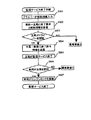
次に、図3から図8に示すフローチャートにより、本例の詳しい動作を説明する。以下略称として、単に主局という場合には主局側装置6を、車両という場合には車両側装置2を指すものとする。まず、図3により、監視サービスの準備手順から説明する。まず、主局通信装置4から領域40に向けて監視サービスの存在を放送(ステップS301)しながら、カメラ7と画像処理部62により、常に画面中で車両(ノイズ領域も含む)を検出して動きを計測し、各車両の動きと位置を所定時間、例えば1分間メモリ61に保持する(ステップS302)。
【0026】
次に、車両は自分の動き、例えば停車したかどうか等の行動状態を、もしくは内蔵の加速度センサなどのセンサ24で計測し、常に所定時間(例えば10秒)メモリ21に保持している。そして、車両が領域40に進入してサービスの存在を受信して発見すると(ステップS303)、車両から主局へサービスを受けるための申込情報aを、メモリ21にある動きの履歴(走行履歴)とあわせて(通信路5や通信装置4を介して)送信する(ステップS304)。
【0027】
申込情報aには、監視サービスを解除するときに主局で必要となる、ドライバー(ユーザ)の認識コード(以下ユーザ認識コード)や緊急時の連絡先などを入れる。ユーザ認識コードはドライバーによって、例えばキーボード80、ICカード81に記憶されたIDや契約番号などを入力装置8を通じてそのまま渡すか、もしくは直接は渡さずに乱数などでスクランブルしてから、もしくは所定の暗号鍵を使って暗号化してから車載側装置20に予め、または監視サービスを受けるたびに入力される。前記の暗号鍵は車両で生成するか、ICカード81等から得るか、主局に送信要求して得る。
【0028】
なお、入力情報は、上記キーボード80、ICカード81の代わりに、指紋や網膜パターン、顔や声や筆跡その他、個人を特定できるあらゆる特徴量の計測値を入力するデバイスが利用できる。また、契約駐車場などにおいて、主局側でユーザ認識コードから連絡先がわかっているような場合もあるので、連絡先は必ずしも必要でない。また、主局は少なくとも監視サービスの終了までは、申込情報aを保持する。また、申込情報aが傍受されて解読され、悪用されるのを防ぐためには、申込情報aを暗号化して送信する必要があるが、解読時間が、少なくとも同一のユーザ認識コードを用いて監視サービスを行う時間(例えば一晩、旅行中の数日、契約IDの変更や破棄までの数年)より長い強度をもつ暗号を使用するのが望ましい。
【0029】
続いて、主局では、ステップS304で送信された走行履歴に最も近い動きの物体を、メモリ61にある計測履歴から検索し、その物体の位置を車外カメラ7で監視すべき位置とする(ステップS305)。なお画像処理部62の計測方法には、例えば電気学会研究会報告RTA91−21(1991年)記載「屋外駐車場における車両計数」の方法が利用できる。
【0030】
上記物体検索方法の一例を、図10に示す。横軸は時間軸で、走行履歴193を受信したときに、メモリ61には3つの物体a〜c(190、191、192)の計測履歴が保持されていたとする。太線は各物体の動きを示し、上部の破線側に接している時間は動いており下部の実線に接している時間は停止していたことを示す。例えば190は時刻t2で出現して2回動いたのちt3で消滅したことを示す。193は上記の例では1分間の長さをもっており、時刻を計測履歴とすり合わせて比較すれば、この例では物体b(191)が最も走行履歴に近いので、物体bの位置を監視すべき車両の位置(又は非常に近い位置)とみなす。
【0031】
なお、上記の車両の行動状態は、外部から車両の速度計出力を取りこんで用いても良い。また、上記の説明では車両が領域40に進入する前の行動状態を、申込情報の送信時に主局に送信しているが、それ以外の方法として、車両が領域40に進入して申込情報を送信した後に自車の行動状態の計測を開始し、計測結果をメモリ21に保持せずに停車するまで順次主局へ送信しつづけ、主局でメモリ61に走行履歴として保持するように変更すると、車両側のメモリ21を使わずにすむ。
【0032】
次に、再び図3に戻り、車両と主局が相互に認証しあうため、予め車両と主局がお互いの認識コードを交換する(ステップS306)。認識コードは、たとえばランダムに生成し、次のように公開鍵方式の暗号通信を用いて交換する。まず車両が主局から認識コード(主局認識コードと呼ぶ)を得るため、車両で暗号鍵aと復号鍵aをペアで生成し、暗号鍵aを主局に送信すると、主局は主局認識コードをランダムに生成して暗号鍵aで暗号化し、車両に送信する。車両はこれを受信すると、復号鍵aによって復号し、主局認識コードを得る。
【0033】
次に、主局が車両から認識コード(車両認識コードと呼ぶ)を得るが、上記と同様にして、まず主局で車両で暗号鍵bと復号鍵bをペアで生成し、暗号鍵bを車両に送信すると、車両は車両認識コードをランダムに生成して暗号鍵bで暗号化し、主局に送信する。主局はこれを受信すると、復号鍵bによって復号し、車両認識コードを得る。これにより、監視サービスの準備が整ったので、イモビライザ90に指示してエンジン9が始動できないようにロックする(ステップS307)。
【0034】
続いて、図4と図5で示す監視サービスの処理ループに入る。以下、主局側の手順を示す図4と、車両側の手順を示す図5を交互に用いて説明する。なお、以下の説明における通信も暗号通信であるが、暗号鍵と復号鍵の交換に関する煩雑な記述は上記と同様のため省略し、交換する情報のみ記述する。
【0035】
主局では、しかるべきタイミングで車両との通信を頻繁に試行することによって、車両が盗難や破壊に遭っていないことを確認する。まず、主局は、上記の通信タイミングを待つ(ステップS401、ステップS402、ステップS403)。この通信タイミングは、通常、メモリ61に格納済みのプログラムで指定のパターンで発生するタイミング (ステップS401)、もしくは車外カメラ7の画像からオペレータがモニタ63を通して異常を発見し、主局側装置6を操作した (ステップS402)、もしくは後述する車両側からの通信によって車両内の異常が通報された(ステップS403)、などのイベントの発生時である。
【0036】
プログラムの通信パターンは、例えば所定の時間ごと(例えば1分間隔)としたり、数秒から数分の幅でランダムとすればよい。ランダムにすると、通信間隔が長いことを利用して通信の合間に犯行を試みる犯人が、通信の傍受によって次に通信が行われるタイミングを予想してしまうことを防ぎつつ、通信回数を抑えて電力消費や通信経費を減らせる効果がある。
【0037】
次に、通信タイミングが到来すると、主局は、車両に対して主局認識コードをリクエストする(ステップS404)。車両は主局からのリクエストを待っており(ステップS501)、リクエストを受信するとすぐには回答せず、逆に主局を認証するために車両から主局に向けて車両認識コードをリクエストする(ステップS502)。
【0038】
主局は、車両からのリクエストを待ち(ステップS405)、リクエストを受信すると車両認識コードを回答して自分が正当な主局であることを伝えるとともに、次回の通信に用いる新たな主局認識コードを生成し、伝える(ステップS407)。車両は主局から車両認識コードの回答を受け(ステップS503)、前回の通信で伝えたコードと矛盾しないことを確認して主局を認証し(ステップS505)、正当であれば主局に対して前回の通信で伝えられている主局認識コードを回答して自分が正当な車両であることを伝えると共に、次回の通信に用いる新たな車両認識コードを生成し、伝える(ステップS506)。
【0039】
なお、ステップS405またはステップS408で所定の時間内に車両から回答がない場合、たとえば通信キャリア信号が途絶えていないかどうかによって通信状態を調べ、通信自体は可能であれば、車両の不正な回答または通信エラーを示す異常事態1に分類し、通信ができない状態であれば通信妨害または通信不良を示す通信異常1に分類する(ステップS406)。また、ステップS409で認証失敗の場合は車両の不正な回答として異常事態2に分類する(ステップS409)。
【0040】
また、異常事態1の場合は、再度ステップS404からステップS409の手順を実行しなおせば、通信エラーによる誤分類をある程度抑制できる。さらに車両側でも同様に、ステップS501またはステップS503で所定の時間内に主局からの回答がない場合、上記と同様に通信状態を調べ、通信自体は可能であれば異常事態3、不可能であれば通信異常2と分類する(ステップS504)。
【0041】
また、ステップS505で認証失敗の場合は主局の不正な回答として異常事態3に分類する。なお、異常事態3や通信異常2の発生時には、車内の警報装置を鳴動させる、イモビライザ90によりエンジン始動をロックする、携帯電話等によるドライバーや警察への通報を試みる、など従来型の盗難防止措置をとるとともに、異常事態3の場合にはさらに、正当な主局がステップステップS403で異常通報を受信することを期待して、主局への異常通報を試みる。
【0042】
通信に用いる認識コードは、仮に犯人が通信を傍受して認識コードを解読し、偽の通信装置を用意して主局や車両になりすまそうと試みても、上記のように毎回更新しておくとともに、解読された時点で次の通信がすでに終わり再度認識コードが更新されているようにしておけば、犯人が得た認識コードは既に無効となっているので、そのような不正な試みを防止できる。暗号の強度と通信にかかる情報量(いいかえれば通信コスト)にはトレードオフがあることが多いので、暗号の強度は解読時間が、例えば平均の、あるいは最大の通信時間間隔より長くなるように選択するのが望ましい。以上のようにして、監視サービスが実行される。
【0043】
つづいて、図6により、上記監視サービスのステップステップS403に異常事態を通知するとともに、車内の状況確認のための画像を送信する車内監視の手順例を説明する。まず、車内を常にセンサ24で変化がないか監視する(ステップS601)。センサには人が進入したり、車両が傾けられたり車載側装置2が移動されたことを検知する振動センサや音センサ、または車内カメラ23と画像処理部22で構成され、画像処理で車内の動きを検知する画像センサなどを使用する。また、図では車載側装置2に内蔵のセンサのみ示したが、車両に装備された外部接続のセンサや、不正に操作されたときにそれを通知する認証手段8も本手順でいうセンサの1つと考える。
【0044】
上記のセンサにて異常事態(異常事態4)が検知されると、次に、車内カメラ23で車内の映像を撮像し(ステップS602)、異常事態4の発生を知らせる信号とともに映像を主局に送信する(ステップS603)。そして、所定のタイムアウトまで主局からの解除信号を待ち(ステップS604)、主局で誤報と判定されたことによる解除信号を受信の場合はステップS601に復帰し、主局で異常と確定されたことによる確定信号を受信するか、タイムアウトになった場合には警報音、通報、エンジン始動ロックなどの盗難防止措置を講じる。
【0045】
つづいて、図7により、車外監視カメラ7の画像を画像メモリ65を用いて記録する手順を説明する。まず、通信路5を通じて供給されるカメラ7の映像を、所定時間分(たとえば5分)の画像を繰り返し上書き記録するための画像メモリ65に記録開始する(ステップS701)。次に、異常事態1〜4および通信異常1の発生を待ち(ステップS902)、異常事態4以外が発生するか、異常事態4の発生かつドライバーが監視サービスの終了手続き中でなければ(ステップS703)、画像メモリ65への記録を停止してそれまでの画像が上書きされないよう保存し(ステップS704)、車外監視カメラ7を当該車両の位置をより詳細に撮像できるように制御して再び映像を記録して保存し(ステップS705)、それらの映像をモニタ63によりオペレータに表示しながら注意を促す(ステップS706)。
【0046】
オペレータはモニタを確認して誤報か異常事態かを判断し(ステップS707)、誤報の場合は車両に解除信号(ステップS709)を送信し、異常事態の場合は車両に異常確定信号(ステップS708)を送信して警報・通報・ゲート11の遠隔閉鎖操作などの措置を講じる。
【0047】
最後に、図8により、ドライバーが監視サービスを終了する手順を説明する。まず、ドライバーが終了操作を始め、監視サービス準備時と同様に、例えばキーボード80、ICカード81等からの入力を行うと、入力装置8が主局に認証してもらうための解除コードを出力して車載側装置20に渡す(ステップS801)。解除コードは準備時のユーザ認識コードそのものか、ユーザ認識コードと対になって一意に決まる対コードである。
【0048】
準備時に送信したユーザ認識コードと終了時に送信する対コードのセットの例としては、契約者IDと契約時に設定したパスワード、暗号化したユーザ入力情報とそれを復号化する復号鍵などのように、主局が対コードを知っているか、主局が対コードを使って正しく元の情報を復元できるようなコードである。
【0049】
つづいて、車両が主局に解除コードと主局認識コードを含む解除情報を送って終了要求を行うと(ステップS802)、主局が終了操作に入り、解除コードからドライバーを認証する(ステップS803)(車両の認証も行う)。ドライバーの認証は、解除コードが例えば準備時のユーザ認識コードそのものの場合には同一かどうかを確かめることで行え、準備時のユーザ認識コードが暗号化された情報で、解除コードが復号鍵である場合には、ユーザ認識コードを復号化して取り出したもとの情報が正当かどうかを確かめることで行える。
【0050】
そして、認証できた場合には主局が車両に終了許可を(車両認識コードとともに)送信し(ステップS804)、主局側がサービスを終了する(ステップS805)。車両は、主局から終了許可が送られたと認めると(ステップS806)、エンジンのロックを解除してサービスを終了する(ステップS807)。また、ステップS803かステップS805で認証できなかった場合には、それぞれ前記の異常事態2(主局側が不正発見)、異常事態3(車両側で不正発見)となり、監視サービスを終了せずに前記の処置を行う。
【0051】
以上のようにして、監視サービスが実現されるが、そのための通信は、公開鍵方式や共通鍵方式を使って説明した本例のように、個々の通信毎に暗号化を行う方式や、またはインターネットで用いられるSSL(Secure Socket Layer)のように通信全体を暗号化する方式等、種々の暗号通信方式を利用して暗号化しておくことが望ましい。なお、主局側の通信装置としては、通信範囲が狭くてもよいため、携帯電話基地局のような広域通信装置よりもむしろ、DSRC(Dedicated Short Range Communication)とよばれる狭域通信装置、PHS基地局、無線LAN装置、Blue Tooth装置などの小規模の通信装置の方が適する。
【0052】
実施の形態2.
次に、図9により実施の形態2を示す。構成は、図1から画像処理部62を除いただけであるので省略する。また、主要機器の配置は図2と同様である。本例は、契約駐車場のように、車両の停車位置が決まっており、その位置情報を主局側で持つことができる利用環境を想定している。また、本例では、同時に特許出願中の「車両盗難検出システムのプログラム更新方法」を用いて、車両から通信手順を規定するプログラムをアップロードするので、ドライバーは自分が安全だと思う所望の通信手順を使用できる。
【0053】
図9において、まず、主局通信装置4が実施の形態1と同様にサービスの存在を領域40に向けて放送する(ステップS901)。車両が領域40に進入し、サービスの存在を受信して発見すると(ステップS902)、車両は主局に向け、ユーザ認識コードとしてドライバーの契約IDを含む申込情報bを送信する(ステップS903)。契約IDは予めメモリ21に入力しておくか、またはキーボード80やキー81より認証装置8を通じて得るようにする。
【0054】
主局は申込情報から契約者かどうかの認証を行い(ステップS904)、契約者でなければ無視するが、もし契約者であれば、主局はメモリ61に予め蓄えられた情報から契約IDを使って駐車位置と非常時の連絡先(たとえば携帯電話番号)を検索して決定し(ステップS905)、車両に主局側のリソース情報(たとえば割り当てメモリ量、車外監視カメラの有無と機能、ゲートの有無など)を提供する(ステップS906)。そして、車両がそのリソースに適したプログラムをアップロードすると(ステップS907)、車両と主局の双方でプログラムがスタートする(ステップS908)。これより、以降の動作はプログラムにより規定され、まず、初期設定として車両と主局がそれぞれの認識コードを交換しあうと、監視サービスの準備が終了する。
【0055】
次に監視サービスの処理を開始する。この処理には、実施の形態1と同じく双方向の認証を行う監視サービス手順を実行してもよいが、ここでは片方向の平易な監視サービスについて、図11と図12を用いて説明する。本例では、車両と主局のプログラムが、通信のタイミングに関する共通の情報を予めもっている。
【0056】
まず、車両はプログラムで規定された送信タイミングを待ち(ステップS521)、送信タイミングになると主局へ主局認識コードを送信する。一方、主局は車両の通信を待ち(ステップS421)、プログラムで規定された車両側の送信タイミングで主局認識コードが得られなかった場合には、たとえば通信キャリア信号が途絶えていないかどうかによって通信状態を調べ、通信自体は可能であれば、車両の不正な回答または通信エラーを示す異常事態1に分類し、通信ができない状態であれば通信妨害または通信不良を示す通信異常1に分類する(ステップS424)。
【0057】
主局認識コードを受信した場合には、正当なコードかどうかを認証し(ステップS425)、正当であれば異常事態なし、不正であれば異常事態2とする。また、実施の形態1と同様に、車外カメラ7の画像からオペレータがモニタ63を通して異常を発見し、主局側装置6を操作した(ステップS422)、もしくは後述する車両側からの通信によって車両内の異常が通報された(ステップS423)、などのイベントの発生時にも、ステップS424を実行する。その他、車内監視手順、車外監視手順、監視サービス終了手順は実施の形態1と同様である。
【0058】
【発明の効果】
以上のように、この発明に係る車両盗難検出システムによれば、自車に搭載されて車内の異常を監視し、外部の主局との通信を行うための車載通信装置を接続した車載側装置と、通信路を介して車載側装置との間で通信を行う主局通信装置と、主局通信装置により車載側装置と所定の通信手順に従って通信を行い、車両の異常事態を監視し、異常事態を発見した場合に警報を発したり通報を行う監視サービスを提供する主局とを含む車両盗難検出システムにおいて、監視サービスの準備時に、車両が主局にユーザ識別情報を送信する手段と、監視サービスの終了時に、車両が主局に、前記ユーザ識別情報または前記ユーザ識別情報と一意に対応した解除用識別情報を送信する手段と、主局が、監視サービスの準備時に車両から受信したユーザ識別情報と、監視サービスの終了時に車両から受信した前記ユーザ識別情報または解除用識別情報より、正しいユーザと認証し、車両に監視サービスの終了を許可する情報を送信する手段とを備えることにより、主局が車載側装置を操作するユーザを認証してから解除を許可することにより、犯人が不正に監視サービスを解除することを防ぐと共に、犯人が不正に監視サービスを解除しようとすると、主局で発見できるようになる。
【0059】
また、他の発明に係る車両盗難検出システムによれば、自車に搭載されて車内の異常を監視し、外部の主局との通信を行うための車載通信装置を接続した車載側装置と、通信路を介して車載側装置との間で通信を行う主局通信装置と、主局通信装置により車載側装置と所定の通信手順に従って通信を行い、車両の異常事態を監視し、異常事態を発見した場合に警報を発したり通報を行う監視サービスを提供する主局とを含む車両盗難検出システムにおいて、主局側の通信手順が、車載側装置に対して第1の識別情報を問い合わせるステップと、車載側装置による第1の識別情報の回答の有無と真偽を判定するステップと、車載側装置からの第2の識別情報の問い合わせへの回答を行うステップを含み、車載側装置の通信手順が、主局に対して第2の識別情報を問い合わせるステップと、主局からの第2の識別情報の回答の有無と真偽を判定するステップと、主局からの第1の識別情報の問い合わせへの回答を行うステップを含み、主局が、第1の識別情報を含む正当な情報が正常に送信されていると判断した場合に車両が異常事態でないと判定し、正当な情報が正常に送信されなかったと判断した場合に車両が異常事態にあると判定する異常事態判定手段を備えることにより、車載側装置が主局の問い合わせに対する回答として信号を発信し、主局がそれを監視しつづけているため、盗難にあたって犯人が妨害電波を発信する、電磁波防護シートをかぶせる、送信アンテナを破壊するなどの行為で通信を妨害しても、主局で検知できる。さらに問い合わせ時に常に識別情報を確認することにより、偽情報の発信によって車載側装置になりすまし、主局で車両の異常事態に気づかれないようにする工作を防ぐことができる。また、通信の妨害がすぐに発覚するようにしたことで、通信の妨害行為に対する抑止効果を発揮し、従来の盗難防止装置が車両から主局に送っていたような犯行関連情報の送信も妨害されにくくなる。
【0060】
また、さらに他の発明に係る車両盗難検出システムによれば、自車に搭載されて車内の異常を監視し、外部の主局との通信を行うための車載通信装置を接続した車載側装置と、通信路を介して車載側装置との間で通信を行う主局通信装置と、主局通信装置により車載側装置と所定の通信手順に従って通信を行い、車両の異常事態を監視し、異常事態を発見した場合に警報を発したり通報を行う監視サービスを提供する主局とを含む車両盗難検出システムにおいて、車載側装置の通信手順が、所定の通信手順に従って第1の識別情報を送信するステップを含むと共に、主局の通信手順が、車載側装置による第1の識別情報の回答の有無と真偽を判定するステップを含み、主局が、所定の通信手順に従って第1の識別情報を含む正当な情報が正常に送信されていると判断した場合に車両が異常事態でないと判定し、正当な情報が正常に送信されなかったと判断した場合に車両が異常事態にあると判定する異常事態判定手段を備えることにより、車載側装置が主局との間で事前に取り決めた共通の通信手順に従って自発的に識別情報を発信し、主局がそれを監視しつづけているため、盗難にあたって犯人が妨害電波を発信する、電磁波防護シートをかぶせる、送信アンテナを破壊するなどの行為で通信を妨害しても、主局で検知できる。さらに常に有資格情報を確認することにより、偽情報の発信によって車載側装置になりすまし、主局で車両の異常事態に気づかれないようにする工作を防ぐことができる。また通信の妨害がすぐに発覚するようにしたことで、通信の妨害行為に対する抑止効果を発揮し、従来の盗難防止装置が車両から主局に送っていたような犯行関連情報の送信も妨害されにくくなる。
【0061】
また、主局側の通信手順が、車載側装置に対して第1の識別情報を問い合わせるステップと、車載側装置による第1の識別情報の回答の有無と真偽を判定するステップと、車載側装置からの第2の識別情報の問い合わせへの回答を行うステップを含み、車載側装置の通信手順が、主局に対して第2の識別情報を問い合わせるステップと、主局からの第2の識別情報の回答の有無と真偽を判定するステップと、主局からの第1の識別情報の問い合わせへの回答を行うステップを含み、主局が、第1の識別情報を含む正当な情報が正常に送信されていると判断した場合に車両が異常事態でないと判定し、正当な情報が正常に送信されなかったと判断した場合に車両が異常事態にあると判定する異常事態判定手段を備えることにより、通信の妨害を抑止できる。
【0062】
また、車載側装置の通信手順が、所定の通信手順に従って第1の識別情報を送信するステップを含むと共に、主局の通信手順が、車載側装置による第1の識別情報の回答の有無と真偽を判定するステップを含み、主局が、所定の通信手順に従って第1の識別情報を含む正当な情報が正常に送信されていると判断した場合に車両が異常事態でないと判定し、正当な情報が正常に送信されなかったと判断した場合に車両が異常事態にあると判定する異常事態判定手段を備えることにより、通信の妨害を抑止できる。
【0063】
また、車載側装置は、車内での異常を検知する車内異常検知装置と接続されるかまたはその機能を内蔵しており、車内で異常が検知された場合には、それ以後、主局への車両存在情報の送信を行わないことで、車両で異常事態が生じたときに、車両情報を主局に送られなくなることにより、主局で異常事態を検知できる。
【0064】
また、車載側装置は、車内での異常を検知する車内異常検知手段と、車内を撮像する車内カメラと、車内カメラの画像を蓄えるメモリを備え、車内異常検知装置により車内で異常が検知された場合に、車内カメラで静止画像または動画像を取得して主局への送信を行う手段と、送信の実行後、主局より所定時間以内に異常解除信号が受信されない場合もしくは異常確定信号を受信した場合に異常と判定し、車内の盗難防止装置を作動させる手段を備えることにより、車内の異常が発生したときに、異常発生時に近い時刻の画像を主局に送信することにより、主局側で異常を把握して誤動作を防止できるとともに、通信が行えなくなっている場合には、通信の妨害という事実も用いて異常判定することにより、車内での異常検知結果のみ用いる場合に比べて誤動作を防止できる。
【0065】
また、車内異常検知検知手段は、車内カメラの画像を処理して動きを検知する画像処理装置、または車両または車載側装置自身の振動や移動または破壊による車載側装置の機能不全を検知する、加速度センサまたは振動センサまたは音センサまたは傾きセンサまたはこれらの装置やセンサの組み合わせであることにより、車内で異常事態を検知できる。
【0066】
また、主局で車両の異常事態と判定されたときに車両の停車位置を撮像し、主局に画像を送信することのできる車外監視カメラを備えたことにより、車外にカメラを設置することにより、車両側設備の諸機能が無効化された場合にも異常時の映像を取得できる。
【0067】
また、車載側装置は、自車の移動の有無などの行動状態を計測して保持し、主局に送信する手段を備え、主局は車外監視カメラの映像より車両の位置と行動状態を計測して保持する車両計測手段を備えるとともに、主局が車外監視カメラにより無線通信可能範囲を撮像して計測した行動状態の履歴と存在位置を含む複数の車両計測値から、車載側装置が監視サービスを受ける以前に計測し、監視サービスを受けるときに主局に送信した行動状態の履歴に最も一致する車両計測値を検索する監視車両検索手段と、検索された車両位置をサービス対象の車両の停車位置に設定する車両位置設定手段を備えることにより、車両が自分の位置を知らせなくても、主局の側で監視すべき車両の位置を把握できる。
【0068】
さらに、車載側装置は自車の移動の有無などの行動状態を計測し、主局に送信する手段を備え、主局は車外監視カメラの映像より車両の位置と行動状態を計測して保持する車両計測手段を備えるとともに、主局が車外監視カメラにより無線通信可能範囲を撮像して計測した、行動状態の履歴と存在位置を含む複数の車両計測値から、車載側装置が主局との通信を確立した後に計測を開始し、主局に逐次送信した車両側の行動状態の履歴に最も一致する車両計測値を検索する監視車両検索手段と、検索された車両位置をサービス対象の車両の停車位置に設定する車両位置設定手段を備えることにより、車両が自分の位置を知らせなくても、主局の側で監視すべき車両の位置を把握できる。
【図面の簡単な説明】
【図1】 この発明の実施の形態1に係る車両盗難防止装置の構成を示すブロック図である。
【図2】 図1の主要機器の配置と諸領域を示す説明図である。
【図3】 この発明の実施の形態1に係る監視サービス準備手順を示すフローチャートである。
【図4】 この発明の実施の形態1に係る主局側の監視サービス手順を示すフローチャートである。
【図5】 この発明の実施の形態1に係る車両側の監視サービス手順を示すフローチャートである。
【図6】 この発明の実施の形態1に係る車両側の車内監視手順を示すフローチャートである。
【図7】 この発明の実施の形態1に係る主局側の車外監視手順を示すフローチャートである。
【図8】 この発明の実施の形態1に係る監視サービス終了手順を示すフローチャートである。
【図9】 この発明の実施の形態2に係る監視サービス準備手順を示すフローチャートである。
【図10】 物体検索方法の一例を示す説明図である。
【図11】 この発明の実施の形態2に係る主局側の監視サービス手順を示すフローチャートである。
【図12】 この発明の実施の形態2に係る車両側の監視サービス手順を示すフローチャートである。
【符号の説明】
1 車両、2 車載側装置、3 車載側通信装置、4 主局通信装置、4a アンテナ、4b 本体、5 通信路、6 主局側装置、7 監視カメラ、8 認証手段、10 停車スロット、11 ゲート、90 イモビライザ、9 エンジン、20 CPU、21 メモリ、22 画像処理部、23 車内カメラ、24センサ、40 通信可能領域、60 CPU、61 メモリ、62 画像処理部、63 モニタ、65 画像メモリ、70 撮像可能な領域、80 ID入力用キーボード、81 キー、90 イモビライザ。[0001]
BACKGROUND OF THE INVENTION
The present invention relates to a vehicle theft detection system.
[0002]
[Prior art]
Conventionally, as a vehicle antitheft device, for example, those disclosed in Japanese Patent Application Laid-Open Nos. 9-240431 and 8-268231 have been known. A conventional vehicle antitheft device is provided with means for determining an abnormal situation in the vehicle in order to inform the main station of the occurrence of an abnormal situation such as theft or destruction of the vehicle. The fact was transmitted to the main station together with necessary information such as vehicle position information.
[0003]
[Problems to be solved by the invention]
By the way, communication can be interrupted by simple methods such as transmitting jamming radio waves, covering with an electromagnetic wave protection sheet, or destroying the antenna on the vehicle side. However, with conventional devices, the driver tries to end the monitoring service. The device does not authenticate whether it is a valid driver on the main station side, and the device does not inspect the termination or invalid status of the monitoring service. There was a problem that the station did not understand, and it was useless.
[0004]
First, in Japanese Patent Application Laid-Open No. 8-268231, it is recommended that the driver perform an ending operation where it can be seen from the main station. However, since the device does not check the information input by the driver, the driver's face, etc. It is necessary to hire an operator who performs authentication.
[0005]
Next, in Japanese Patent Laid-Open No. 9-240431, whether or not the driver is a valid driver on the vehicle side and information indicating that the authentication is successful is transmitted to the main station, so that the main station is a valid driver. However, since the main station only believes in the authentication result of the vehicle side, if the criminal sends false information that the authentication was successful from the fake vehicle side device, the main station side cannot distinguish . In addition, even during monitoring services, if the criminal interferes with the transmission of information from the vehicle to the main station, the main station cannot know the occurrence of such an abnormal situation even though it can disable the vehicle. There was a problem. Further, in order for the main station to grasp the position of the vehicle, it is necessary to provide a device such as a GPS for detecting the position information of the own vehicle on the vehicle side and transmit the position information to the main station.
[0006]
The present invention has been made in view of the above-described points, and an object of the present invention is to provide a vehicle theft detection system that can prevent unauthorized release of a monitoring service.
[0007]
[Means for Solving the Problems]
A vehicle theft detection system according to the present invention is mounted on a vehicle, monitors an abnormality in the vehicle, and connects a vehicle-mounted communication device for communicating with an external main station, and a communication path. The main station communication device that communicates with the in-vehicle device and the main station communication device communicates with the in-vehicle device according to a predetermined communication procedure, monitors the abnormal situation of the vehicle, and alerts if an abnormal situation is found In a vehicle theft detection system including a main station that provides a monitoring service that issues or reports, a vehicle transmits user identification information to the main station at the time of preparation of the monitoring service, and at the end of the monitoring service, the vehicle Means for transmitting to the main station the user identification information or the release identification information uniquely corresponding to the user identification information; the user identification information received from the vehicle by the main station during the preparation of the monitoring service; Scan at the end of the from the user identification information or canceling identification information received from the vehicle, to authenticate the correct user, and means for transmitting the information to allow completion of the monitoring service to the vehicle And a means for trial communication for confirming that the vehicle has not been stolen or destroyed by frequently trying to communicate with the vehicle in accordance with a predetermined communication procedure. The communication procedure inquires about the first identification information from the in-vehicle side device, the step of determining the presence / absence and authenticity of the response of the first identification information by the in-vehicle side device, and the second from the in-vehicle side device Including a step of responding to an inquiry about identification information, wherein the communication procedure of the in-vehicle device makes an inquiry about the second identification information to the main station, and whether or not there is an answer to the second identification information from the main station, A step of determining authenticity and a step of replying to the inquiry of the first identification information from the master station, wherein the master station has successfully transmitted legitimate information including the first identification information. If you decide Equipped with an abnormal situation determination means that determines that the vehicle is in an abnormal situation when it is determined that both are not in an abnormal situation and that legitimate information has not been transmitted normally, taking out vehicles and monitoring services that interfere with communication Has a function to detect unauthorized attempts to cancel It is characterized by this.
[0009]
Ma Car The communication procedure of the loading device includes a step of transmitting the first identification information according to a predetermined communication procedure, and the communication procedure of the main station determines whether or not the vehicle-mounted device responds to the first identification information. And determining that the vehicle is not in an abnormal situation when the main station determines that the legitimate information including the first identification information is normally transmitted according to a predetermined communication procedure. It is characterized by comprising an abnormal situation judging means for judging that the vehicle is in an abnormal situation when it is judged that the vehicle has not been normally transmitted.
[0012]
Also, the in-vehicle side device is connected to or has a built-in function of an in-vehicle abnormality detection device that detects an abnormality in the vehicle. Do not send vehicle presence information To detect abnormal situations at the master station It is characterized by this.
[0013]
The in-vehicle side device includes an in-vehicle abnormality detecting means for detecting an abnormality in the vehicle, an in-vehicle camera for imaging the inside of the vehicle, and a memory for storing images of the in-vehicle camera, and the abnormality is detected in the vehicle by the in-vehicle abnormality detecting device. In this case, a means for acquiring a still image or a moving image with an in-vehicle camera and transmitting it to the main station, and after executing the transmission, if the abnormality release signal is not received within a predetermined time from the main station or an abnormality confirmation signal is received. In this case, it is determined that there is an abnormality, and means for operating the antitheft device in the vehicle is provided.
[0014]
The in-vehicle abnormality detection detecting means detects an incompatibility of the image processing apparatus that processes the image of the in-vehicle camera and detects movement, or the malfunction of the in-vehicle apparatus due to vibration, movement, or destruction of the vehicle or the in-vehicle apparatus itself. It is a sensor, a vibration sensor, a sound sensor, a tilt sensor, or a combination of these devices and sensors.
[0015]
In addition, it has an out-of-vehicle monitoring camera that can capture the vehicle stop position and transmit the image to the main station when the main station determines that the vehicle is abnormal. In addition, it has a function to acquire an abnormal video when the function of the vehicle-side equipment is invalidated It is characterized by this.
[0016]
The in-vehicle device also has means for measuring and holding the behavioral state such as the presence or absence of movement of the vehicle and transmitting it to the main station. The main station measures the vehicle position and behavioral state from the video from the outside surveillance camera. The vehicle-mounted side device provides a monitoring service based on a plurality of vehicle measurement values including a history of behavioral states and existing positions measured by the main station by imaging the wireless communicable range with an out-of-vehicle monitoring camera. Monitoring vehicle search means for searching for a vehicle measurement value that most closely matches the history of the behavioral state measured before receiving the monitoring service and transmitted to the main station when receiving the monitoring service, and stopping the vehicle to be serviced based on the searched vehicle position Vehicle position setting means for setting the position is provided.
[0017]
Furthermore, the in-vehicle device is provided with means for measuring the behavioral state such as the presence / absence of movement of the own vehicle and transmitting it to the main station, and the main station measures and holds the position and behavioral state of the vehicle from the video of the outside surveillance camera. The in-vehicle device communicates with the main station from a plurality of vehicle measurement values including a history of the behavioral state and the existing position, which are provided with vehicle measurement means and the main station measures and measures the wireless communicable range with the outside monitoring camera. Monitoring vehicle search means for searching for a vehicle measurement value that most closely matches the history of the behavioral state of the vehicle that has been transmitted to the main station sequentially, and the vehicle position to be serviced is stopped. Vehicle position setting means for setting the position is provided.
[0018]
DETAILED DESCRIPTION OF THE INVENTION
Embodiment 1 FIG.
In this example, a parking lot where various monitoring devices can be easily installed will be described as an example. However, the place where the monitoring service is provided may be on a road or a garage, and the vehicle is not only a car but also a motorcycle or a bicycle. There may be. 1 is a block diagram showing a configuration of a vehicle theft detection system according to Embodiment 1 of the present invention. As shown in FIG. 1, the vehicle 1 includes an in-vehicle device 2, an in-
[0019]
The main station providing the service is virtually secured on a communication network such as the Internet, which transmits the main station communication device 4, communication contents, camera video (digitalized) and camera control signals. Communication channel 5, main station side device 6, monitoring camera 7, monitor 63 for the operator on the main station side, and
[0020]
FIG. 2 is an explanatory view showing the arrangement and various areas of the main device. In FIG. 2, 10 is a stop slot of the vehicle 1, and 11 is a gate for preventing unauthorized entry of the vehicle.
[0021]
Further, in order to determine the occurrence of an abnormal situation due to the interruption of communication, if the cost permits, it is desirable to reduce the
[0022]
In the figure, the configuration in which the camera 7 outputs a digital image or is converted into a digital image is shown in which the communication path 5 is shared. However, the output may be an analog image. Therefore, it is necessary to divide the communication path 5 into two or more systems of analog and digital. Needless to say, the communication path 5 may actually be a dedicated communication line instead of being virtual.
[0023]
First, the outline of the operation sequence of this example will be described in a greatly simplified manner. When the vehicle 1 enters the imaging area of the camera 7, the image processing unit 62 of the main station 6 measures the position and movement of the vehicle 1 from the image, and stores a history of measurement values. The vehicle 1 measures the movement of the vehicle with the acceleration sensor 24 and the like, and sends the history of movement to the main station 6 using the
[0024]
In addition, the vehicle 1 transmits application information including, for example, a contract ID to the main station 6. Subsequently, the vehicle 1 and the main station 6 exchange each other's recognition codes, and thereafter try communication for requesting each other's recognition codes at a timing according to a predetermined communication procedure. If communication is impossible or the recognition code is invalid, the camera 7 is controlled to capture the position of the vehicle 1, the image is stored in the
[0025]
Next, the detailed operation of this example will be described with reference to the flowcharts shown in FIGS. Hereinafter, as an abbreviation, the main station apparatus 6 is simply referred to as the main station, and the vehicle apparatus 2 is referred to as the vehicle. First, the preparation procedure of the monitoring service will be described with reference to FIG. First, while broadcasting the presence of the monitoring service from the main station communication device 4 to the area 40 (step S301), the camera 7 and the image processing unit 62 always detect the vehicle (including the noise area) on the screen. The movement is measured, and the movement and position of each vehicle are held in the memory 61 for a predetermined time, for example, for one minute (step S302).
[0026]
Next, the vehicle measures its own movement, for example, whether or not it has stopped, or a sensor 24 such as a built-in acceleration sensor, and always holds it in the memory 21 for a predetermined time (for example, 10 seconds). When the vehicle enters the
[0027]
The application information a includes a driver (user) identification code (hereinafter referred to as a user identification code), an emergency contact information, and the like that are required by the master station when canceling the monitoring service. For example, the ID or contract number stored in the keyboard 80 or
[0028]
As the input information, instead of the keyboard 80 and the
[0029]
Subsequently, the main station searches the measurement history in the memory 61 for an object that moves closest to the travel history transmitted in step S304, and sets the position of the object as a position to be monitored by the outside camera 7 (step S305). As a measuring method of the image processing unit 62, for example, a method of “vehicle counting in an outdoor parking lot” described in RTA91-21 (1991) of the Institute of Electrical Engineers of Japan report can be used.
[0030]
An example of the object search method is shown in FIG. It is assumed that the horizontal axis is a time axis, and when the
[0031]
Note that the behavior state of the vehicle described above may be used by incorporating the speedometer output of the vehicle from the outside. In the above description, the behavior state before the vehicle enters the
[0032]
Next, returning to FIG. 3 again, since the vehicle and the main station mutually authenticate each other, the vehicle and the main station exchange each other's recognition code in advance (step S306). The recognition code is generated at random, for example, and exchanged using public key encryption communication as follows. First, in order for the vehicle to obtain a recognition code (referred to as a main station recognition code) from the main station, the vehicle generates a pair of the encryption key a and the decryption key a, and transmits the encryption key a to the main station. A recognition code is randomly generated, encrypted with the encryption key a, and transmitted to the vehicle. Upon receiving this, the vehicle decrypts it with the decryption key a to obtain a master station recognition code.
[0033]
Next, the main station obtains a recognition code (referred to as a vehicle recognition code) from the vehicle. In the same manner as described above, the main station first generates a pair of the encryption key b and the decryption key b in the vehicle, and obtains the encryption key b. When transmitted to the vehicle, the vehicle randomly generates a vehicle recognition code, encrypts it with the encryption key b, and transmits it to the main station. When the main station receives this, it decrypts it with the decryption key b to obtain a vehicle recognition code. As a result, the monitoring service is ready, and the
[0034]
Subsequently, the monitoring service processing loop shown in FIGS. 4 and 5 is entered. Hereinafter, description will be made by alternately using FIG. 4 showing the procedure on the main station side and FIG. 5 showing the procedure on the vehicle side. Note that the communication in the following description is also encryption communication, but the complicated description regarding the exchange of the encryption key and the decryption key is the same as described above, so that only the information to be exchanged is described.
[0035]
The main station confirms that the vehicle has not been stolen or destroyed by frequently trying to communicate with the vehicle at an appropriate timing. First, the main station waits for the above communication timing (step S401, step S402, step S403). This communication timing is usually the timing that occurs in a specified pattern in the program stored in the memory 61 (step S401), or the operator detects an abnormality through the monitor 63 from the image of the camera 7 outside the vehicle and It is when an event such as an operation (step S402) or an abnormality in the vehicle is notified by communication from the vehicle side described later (step S403).
[0036]
The communication pattern of the program may be, for example, every predetermined time (for example, at an interval of 1 minute) or random within a range of several seconds to several minutes. If random, the criminal who tries to commit a crime in the middle of communication using the long communication interval prevents the prediction of the next communication timing due to the interception of the communication, while reducing the number of communication and power This has the effect of reducing consumption and communication costs.
[0037]
Next, when the communication timing arrives, the main station requests the main station recognition code from the vehicle (step S404). The vehicle waits for a request from the main station (step S501), and does not respond as soon as the request is received, but conversely requests a vehicle identification code from the vehicle to the main station in order to authenticate the main station ( Step S502).
[0038]
The master station waits for a request from the vehicle (step S405). When the master station receives the request, it responds with a vehicle recognition code to inform that it is a legitimate master station and a new master station recognition code used for the next communication. Is generated and transmitted (step S407). The vehicle receives the vehicle identification code response from the main station (step S503), confirms that it is consistent with the code transmitted in the previous communication, authenticates the main station (step S505). The main station recognition code transmitted in the previous communication is answered to notify that the vehicle is a valid vehicle, and a new vehicle recognition code used for the next communication is generated and transmitted (step S506).
[0039]
If there is no response from the vehicle within a predetermined time in step S405 or step S408, for example, the communication state is checked based on whether or not the communication carrier signal is interrupted. If it is classified into an abnormal situation 1 indicating a communication error and communication is not possible, it is classified as a communication abnormality 1 indicating communication interruption or communication failure (step S406). If the authentication fails in step S409, the vehicle is classified as an abnormal situation 2 as an incorrect answer of the vehicle (step S409).
[0040]
In the case of an abnormal situation 1, if the procedure from step S404 to step S409 is performed again, misclassification due to a communication error can be suppressed to some extent. Further, similarly, if there is no response from the main station within a predetermined time in step S501 or step S503 on the vehicle side, the communication state is checked in the same manner as described above, and if the communication itself is possible,
[0041]
If authentication fails in step S505, it is classified as an
[0042]
Even if the criminal intercepts the communication and decodes the recognition code and tries to impersonate the main station or vehicle by preparing a fake communication device, the recognition code used for communication is updated as described above. In addition, if the next communication is already finished and the recognition code is updated again when it is decrypted, the recognition code obtained by the criminal is already invalid. Can be prevented. Since there is often a trade-off between encryption strength and the amount of information required for communication (in other words, communication cost), the encryption strength is selected so that the decryption time is longer than the average or maximum communication time interval, for example. It is desirable to do. The monitoring service is executed as described above.
[0043]
Next, referring to FIG. 6, an example of a procedure for in-vehicle monitoring in which an abnormal situation is notified to step S403 of the monitoring service and an image for checking the in-vehicle situation is transmitted will be described. First, the inside of the vehicle is always monitored for changes by the sensor 24 (step S601). The sensor is composed of a vibration sensor or a sound sensor that detects that a person has entered, the vehicle is tilted, or the in-vehicle device 2 is moved, or an in-
[0044]
When an abnormal situation (abnormal situation 4) is detected by the above sensor, the in-
[0045]
Next, a procedure for recording an image of the outside surveillance camera 7 using the
[0046]
The operator checks the monitor to determine whether it is a false alarm or an abnormal situation (step S707). In the case of a false alarm, a release signal (step S709) is transmitted to the vehicle. When an abnormal situation occurs, an abnormality confirmation signal (step S708) is sent to the vehicle. And take measures such as alarming, reporting, and remotely closing the gate 11.
[0047]
Finally, a procedure for the driver to end the monitoring service will be described with reference to FIG. First, when the driver starts an end operation and inputs from, for example, the keyboard 80, the
[0048]
As an example of the set of user identification code sent at the time of preparation and the pair code sent at the end, the contractor ID and the password set at the time of the contract, the encrypted user input information and the decryption key for decrypting it, etc. The main station knows the pair code, or the main station can correctly restore the original information using the pair code.
[0049]
Subsequently, when the vehicle sends a release information including a release code and a master station recognition code to the main station to make an end request (step S802), the main station enters an end operation and authenticates the driver from the release code (step S803). (The vehicle is also certified). Driver authentication can be performed by confirming whether or not the release code is the same as the user recognition code itself at the time of preparation, for example. The user recognition code at the time of preparation is encrypted information, and the release code is a decryption key. In this case, it is possible to confirm whether the original information extracted by decoding the user recognition code is valid.
[0050]
If the authentication is successful, the main station transmits an end permission (together with the vehicle recognition code) to the vehicle (step S804), and the main station ends the service (step S805). When the vehicle recognizes that the end permission is sent from the main station (step S806), the vehicle unlocks the engine and ends the service (step S807). In addition, if authentication cannot be performed in step S803 or step S805, the abnormal situation 2 (master station side finds fraud) and the abnormal situation 3 (vehicle side finds fraud) occur, and the monitoring service is not terminated. Take action.
[0051]
As described above, the monitoring service is realized, and the communication for that purpose is a method of performing encryption for each communication, as in this example described using the public key method or the common key method, or It is desirable to encrypt using various encryption communication methods such as a method of encrypting the entire communication like SSL (Secure Socket Layer) used on the Internet. Since the communication range on the main station side may be narrow, a narrow range communication device called PRC (Dedicated Short Range Communication), rather than a wide range communication device such as a mobile phone base station, PHS Small-scale communication devices such as base stations, wireless LAN devices, and blue tooth devices are more suitable.
[0052]
Embodiment 2. FIG.
Next, a second embodiment is shown in FIG. The configuration is omitted because only the image processing unit 62 is omitted from FIG. The arrangement of main devices is the same as that shown in FIG. This example assumes a use environment in which the stop position of the vehicle is determined and the position information can be held on the main station side as in the contract parking lot. In addition, in this example, since the program for defining the communication procedure is uploaded from the vehicle using the “pending method for vehicle theft detection system” which is pending at the same time, the driver wants the desired communication procedure that he / she thinks is safe Can be used.
[0053]
In FIG. 9, first, the main station communication device 4 broadcasts the existence of a service toward the
[0054]
The master station authenticates whether it is a contractor from the application information (step S904) and ignores it unless it is a contractor. If it is a contractor, the master station obtains a contract ID from information stored in the memory 61 in advance. Use it to search and determine the parking position and emergency contact information (for example, a mobile phone number) (step S905), and resource information on the main station side for the vehicle (for example, the allocated memory amount, presence / absence and function of the outside surveillance camera, gate Or not) (step S906). When the vehicle uploads a program suitable for the resource (step S907), the program starts on both the vehicle and the main station (step S908). Thus, the subsequent operations are defined by the program. First, when the vehicle and the main station exchange their respective recognition codes as an initial setting, the preparation of the monitoring service ends.
[0055]
Next, monitoring service processing is started. In this process, a monitoring service procedure for performing bidirectional authentication may be executed as in the first embodiment. Here, a simple monitoring service in one direction will be described with reference to FIGS. In this example, the vehicle and main station programs have in advance common information regarding the timing of communication.
[0056]
First, the vehicle waits for the transmission timing specified by the program (step S521), and transmits the master station recognition code to the master station when the transmission timing is reached. On the other hand, the main station waits for communication of the vehicle (step S421), and if the main station recognition code is not obtained at the vehicle-side transmission timing specified in the program, for example, depending on whether the communication carrier signal is not interrupted If the communication state is checked and the communication itself is possible, it is classified as an abnormal situation 1 indicating an incorrect answer or communication error of the vehicle, and if it is not possible to communicate, it is classified as a communication abnormality 1 indicating communication interruption or communication failure. (Step S424).
[0057]
If the master station recognition code is received, it is authenticated whether it is a valid code (step S425). Further, as in the first embodiment, the operator discovers an abnormality from the image of the camera 7 outside the vehicle through the monitor 63 and operates the main station side device 6 (step S422), or the inside of the vehicle by communication from the vehicle side described later. Step S424 is also executed when an event such as the notification of the abnormality (step S423) occurs. In addition, the in-vehicle monitoring procedure, the out-of-vehicle monitoring procedure, and the monitoring service end procedure are the same as those in the first embodiment.
[0058]
【The invention's effect】
As described above, according to the vehicle theft detection system according to the present invention, an in-vehicle device connected to an in-vehicle communication device that is mounted on the host vehicle, monitors abnormalities in the vehicle, and communicates with an external main station. And the main station communication device that communicates with the in-vehicle side device via the communication path, and the main station communication device communicates with the in-vehicle side device according to a predetermined communication procedure, monitors the abnormal situation of the vehicle, In a vehicle theft detection system including a main station that provides a monitoring service that issues an alarm or reports when a situation is detected, a means for the vehicle to transmit user identification information to the main station at the time of preparation of the monitoring service, and monitoring At the end of the service, the vehicle transmits to the main station the user identification information or the release identification information uniquely corresponding to the user identification information, and the user received from the vehicle by the main station during the preparation of the monitoring service By providing another information and means for authenticating a correct user from the user identification information or the release identification information received from the vehicle at the end of the monitoring service, and transmitting information for permitting the vehicle to end the monitoring service, By allowing the main station to authenticate the user who operates the in-vehicle side device and permitting the release, the criminal prevents the monitoring service from being illegally released, and if the criminal tries to release the monitoring service illegally, Can be found at.
[0059]
In addition, according to the vehicle theft detection system according to another invention, the in-vehicle device connected to the in-vehicle communication device for monitoring an abnormality in the vehicle mounted on the own vehicle and communicating with the external main station, The main station communication device that communicates with the in-vehicle side device via the communication path, and the main station communication device communicates with the in-vehicle side device according to a predetermined communication procedure, monitors the abnormal situation of the vehicle, and In a vehicle theft detection system including a main station that provides a monitoring service that issues a warning or reports when it is found, a communication procedure on the main station side inquires of the in-vehicle apparatus for first identification information; A communication procedure of the in-vehicle side device, including the step of determining the presence / absence and authenticity of the response of the first identification information by the in-vehicle side device and the step of responding to the inquiry of the second identification information from the in-vehicle side device But for the main station A step of inquiring about the identification information of 2, a step of determining whether or not there is a reply of the second identification information from the main station, and a step of performing a reply to the inquiry of the first identification information from the main station When the main station determines that the legitimate information including the first identification information is normally transmitted, it determines that the vehicle is not in an abnormal situation, and the legitimate information is not transmitted normally. By providing an abnormal situation determination means that determines that the vehicle is in an abnormal situation, the in-vehicle device sends a signal as an answer to the inquiry of the main station, and the main station continues to monitor it. Even if communication is interrupted by actions such as sending jamming radio waves, covering with an electromagnetic wave protection sheet, or destroying the transmitting antenna, the main station can detect it. Further, by always confirming the identification information at the time of inquiry, it is possible to prevent the main station from impersonating the on-vehicle side device and not being aware of the abnormal situation of the vehicle at the main station. In addition, the fact that communication interruptions are immediately detected provides a deterrent effect against communication interruptions, and also prevents transmission of crime-related information that a conventional antitheft device sent from the vehicle to the main station. It becomes difficult to be done.
[0060]
In addition, according to the vehicle theft detection system according to still another invention, an in-vehicle device connected to an in-vehicle communication device that is mounted in the host vehicle and monitors an abnormality in the vehicle and communicates with an external main station; The main station communication device that communicates with the in-vehicle device via the communication path, and the main station communication device communicates with the in-vehicle device according to a predetermined communication procedure, monitors the abnormal situation of the vehicle, In a vehicle theft detection system that includes a main station that provides a monitoring service that issues an alarm or reports when an alarm is detected, the communication procedure of the in-vehicle device transmits first identification information according to a predetermined communication procedure And the communication procedure of the main station includes the step of determining the presence / absence and authenticity of the response of the first identification information by the in-vehicle device, and the main station includes the first identification information according to a predetermined communication procedure Legitimate information is normal By determining that the vehicle is not in an abnormal state when it is determined that it is transmitted, and having an abnormal state determination means that determines that the vehicle is in an abnormal state when it is determined that the legitimate information has not been transmitted normally, The in-vehicle device voluntarily transmits identification information according to a common communication procedure agreed with the main station in advance, and the main station continues to monitor it, so the criminal transmits jamming radio waves during theft. Even if communication is interrupted by actions such as covering with an electromagnetic wave protection sheet or destroying the transmitting antenna, the main station can detect it. Furthermore, by constantly checking the qualified information, it is possible to prevent the main station from impersonating the vehicle-mounted device by sending out false information so that the main station is not aware of the abnormal situation of the vehicle. In addition, the fact that communication interruptions are detected immediately demonstrates a deterrent effect against communication interruptions, and also prevents transmission of crime-related information that a conventional anti-theft device sent from the vehicle to the main station. It becomes difficult.
[0061]
Further, the communication procedure on the main station side inquires the first identification information to the in-vehicle side device, the presence / absence of the answer of the first identification information by the in-vehicle side device, and the step of judging the authenticity, A step of responding to the inquiry of the second identification information from the apparatus, wherein the communication procedure of the in-vehicle side apparatus inquires the second identification information to the main station, and the second identification from the main station Including a step of determining the presence / absence and authenticity of an information response, and a step of responding to an inquiry about the first identification information from the main station, wherein the main station has normal information including the first identification information normal By determining that the vehicle is not in an abnormal state when it is determined that the vehicle is being transmitted to the vehicle, and having an abnormal state determination unit that determines that the vehicle is in an abnormal state when it is determined that the legitimate information has not been transmitted normally. , Disruption of communication It can be stopped.
[0062]
In addition, the communication procedure of the in-vehicle device includes a step of transmitting the first identification information in accordance with a predetermined communication procedure, and the communication procedure of the main station determines whether the response of the first identification information by the in-vehicle device is true or not. Including a step of determining false, the main station determines that the vehicle is not abnormal when it determines that the legitimate information including the first identification information is normally transmitted according to a predetermined communication procedure, By providing an abnormal situation determination means that determines that the vehicle is in an abnormal situation when it is judged that the information has not been transmitted normally, interference of communication can be suppressed.
[0063]
Also, the in-vehicle side device is connected to or has a built-in function of an in-vehicle abnormality detection device that detects an abnormality in the vehicle. By not transmitting the vehicle presence information, when an abnormal situation occurs in the vehicle, the abnormal situation can be detected at the main station by preventing the vehicle information from being sent to the main station.
[0064]
The in-vehicle side device includes an in-vehicle abnormality detecting means for detecting an abnormality in the vehicle, an in-vehicle camera for imaging the inside of the vehicle, and a memory for storing images of the in-vehicle camera, and the abnormality is detected in the vehicle by the in-vehicle abnormality detecting device. In this case, a means for acquiring a still image or a moving image with an in-vehicle camera and transmitting it to the main station, and after executing the transmission, if the abnormality release signal is not received within a predetermined time from the main station or an abnormality confirmation signal is received. If a failure occurs in the vehicle, the master station side transmits an image close to the time of the failure to the main station. Can detect malfunctions and prevent malfunctions, and when communication is not possible, use only the abnormal detection result in the car by judging the abnormality using the fact of communication interference The malfunction can be prevented in comparison with the case.
[0065]
The in-vehicle abnormality detection detecting means detects an incompatibility of the image processing apparatus that processes the image of the in-vehicle camera and detects movement, or the malfunction of the in-vehicle apparatus due to vibration, movement, or destruction of the vehicle or the in-vehicle apparatus itself. By being a sensor, a vibration sensor, a sound sensor, a tilt sensor, or a combination of these devices and sensors, an abnormal situation can be detected in the vehicle.
[0066]
In addition, by providing an out-of-vehicle monitoring camera that can capture the vehicle's stop position and transmit the image to the main station when the main station determines that the vehicle is in an abnormal situation, Even when various functions of the vehicle-side equipment are invalidated, it is possible to obtain a video at the time of abnormality.
[0067]
The in-vehicle device also has means for measuring and holding the behavioral state such as the presence or absence of movement of the vehicle and transmitting it to the main station. The main station measures the vehicle position and behavioral state from the video from the outside surveillance camera. The vehicle-mounted side device provides a monitoring service based on a plurality of vehicle measurement values including a history of behavioral states and existing positions measured by the main station by imaging the wireless communicable range with an out-of-vehicle monitoring camera. Monitoring vehicle search means for searching for a vehicle measurement value that most closely matches the history of the behavioral state measured before receiving the monitoring service and transmitted to the main station when receiving the monitoring service, and stopping the vehicle to be serviced based on the searched vehicle position By providing the vehicle position setting means for setting the position, the position of the vehicle to be monitored can be grasped on the main station side without the vehicle notifying its own position.
[0068]
Furthermore, the in-vehicle device is provided with means for measuring the behavioral state such as the presence / absence of movement of the own vehicle and transmitting it to the main station, and the main station measures and holds the position and behavioral state of the vehicle from the video of the outside surveillance camera. The in-vehicle device communicates with the main station from a plurality of vehicle measurement values including a history of the behavioral state and the existing position, which are provided with vehicle measurement means and the main station measures and measures the wireless communicable range with the outside monitoring camera. Monitoring vehicle search means for searching for a vehicle measurement value that most closely matches the history of the behavioral state of the vehicle that has been transmitted to the main station sequentially, and the vehicle position to be serviced is stopped. By providing the vehicle position setting means for setting the position, the position of the vehicle to be monitored can be grasped on the main station side without the vehicle notifying its own position.
[Brief description of the drawings]
FIG. 1 is a block diagram showing a configuration of a vehicle antitheft device according to Embodiment 1 of the present invention.
FIG. 2 is an explanatory diagram showing the arrangement and various areas of the main device in FIG. 1;
FIG. 3 is a flowchart showing a monitoring service preparation procedure according to the first embodiment of the present invention.
FIG. 4 is a flowchart showing a monitoring service procedure on the main station side according to Embodiment 1 of the present invention;
FIG. 5 is a flowchart showing a monitoring service procedure on the vehicle side according to the first embodiment of the present invention.
FIG. 6 is a flowchart showing an in-vehicle monitoring procedure on the vehicle side according to Embodiment 1 of the present invention.
FIG. 7 is a flowchart showing an out-of-vehicle monitoring procedure on the main station side according to Embodiment 1 of the present invention.
FIG. 8 is a flowchart showing a monitoring service ending procedure according to the first embodiment of the present invention.
FIG. 9 is a flowchart showing a monitoring service preparation procedure according to the second embodiment of the present invention.
FIG. 10 is an explanatory diagram illustrating an example of an object search method.
FIG. 11 is a flowchart showing a monitoring service procedure on the main station side according to Embodiment 2 of the present invention;
FIG. 12 is a flowchart showing a monitoring service procedure on the vehicle side according to Embodiment 2 of the present invention.
[Explanation of symbols]
DESCRIPTION OF SYMBOLS 1 Vehicle, 2 vehicle-mounted side apparatus, 3 vehicle-mounted side communication apparatus, 4 main station communication apparatus, 4a antenna, 4b main body, 5 communication channel, 6 main station side apparatus, 7 monitoring camera, 8 authentication means, 10 stop slot, 11 gate , 90 Immobilizer, 9 Engine, 20 CPU, 21 Memory, 22 Image processing unit, 23 Vehicle camera, 24 Sensor, 40 Communication area, 60 CPU, 61 Memory, 62 Image processing unit, 63 Monitor, 65 Image memory, 70 Imaging Possible area, 80 ID input keyboard, 81 keys, 90 immobilizer.
Claims (8)
通信路を介して車載側装置との間で通信を行う主局通信装置と、主局通信装置により車載側装置と所定の通信手順に従って通信を行い、車両の異常事態を監視し、異常事態を発見した場合に警報を発したり通報を行う監視サービスを提供する主局と
を含む車両盗難検出システムにおいて、
監視サービスの準備時に、車両が主局にユーザ識別情報を送信する手段と、監視サービスの終了時に、車両が主局に、前記ユーザ識別情報または前記ユーザ識別情報と一意に対応した解除用識別情報を送信する手段と、主局が、監視サービスの準備時に車両から受信したユーザ識別情報と、監視サービスの終了時に車両から受信した前記ユーザ識別情報または解除用識別情報より、正しいユーザと認証し、車両に監視サービスの終了を許可する情報を送信する手段とを備え、
さらに所定の通信手順に従って頻繁に車両との通信を試行することによって車両が盗難や破壊に遭っていないことを確認する試行通信の手段を備えており、
上記通信手順としては、
主局側の通信手順が、車載側装置に対して第1の識別情報を問い合わせるステップと、車載側装置による第1の識別情報の回答の有無と真偽を判定するステップと、車載側装置からの第2の識別情報の問い合わせへの回答を行うステップを含み、車載側装置の通信手順が、主局に対して第2の識別情報を問い合わせるステップと、主局からの第2の識別情報の回答の有無と真偽を判定するステップと、主局からの第1の識別情報の問い合わせへの回答を行うステップを含み、
主局が、第1の識別情報を含む正当な情報が正常に送信されていると判断した場合に車両が異常事態でないと判定し、正当な情報が正常に送信されなかったと判断した場合に車両が異常事態にあると判定する異常事態判定手段を備え、通信の妨害を伴う車両の持ち出しや監視サービスの不正な解除の試みを主局側で検出する機能を有する
ことを特徴とする車両盗難検出システム。An in-vehicle device connected to an in-vehicle communication device for monitoring an abnormality in the vehicle mounted on the own vehicle and communicating with an external main station;
The main station communication device that communicates with the in-vehicle side device via the communication path, and the main station communication device communicates with the in-vehicle side device according to a predetermined communication procedure, monitors the abnormal situation of the vehicle, and In a vehicle theft detection system including a main station that provides a monitoring service that issues an alarm or reports when it is discovered,
Means for transmitting user identification information to the main station when the vehicle is prepared for the monitoring service, and identification information for release uniquely corresponding to the user identification information or the user identification information to the main station when the vehicle is terminated And the main station authenticates with the correct user from the user identification information received from the vehicle at the time of preparation of the monitoring service and the user identification information or release identification information received from the vehicle at the end of the monitoring service, Means for transmitting information permitting the vehicle to terminate the monitoring service ,
Furthermore, it has means for trial communication to confirm that the vehicle has not been stolen or destroyed by frequently trying to communicate with the vehicle according to a predetermined communication procedure,
As the above communication procedure,
The communication procedure on the main station side inquires about the first identification information from the in-vehicle side device, the step of determining the presence / absence of authenticity of the first identification information by the in-vehicle side device, and the authenticity from the in-vehicle side device In response to the second identification information inquiry, wherein the communication procedure of the in-vehicle device makes an inquiry about the second identification information to the main station, and the second identification information from the main station Determining the presence / absence and authenticity of a response, and performing a response to the inquiry of the first identification information from the master station,
When the main station determines that the legitimate information including the first identification information is normally transmitted, the vehicle determines that the vehicle is not in an abnormal situation, and the legitimate information is not normally transmitted. Vehicle theft detection characterized by having an abnormal situation judging means for judging that the vehicle is in an abnormal situation and having the function of detecting on the main station side the taking out of the vehicle accompanied by communication interruption and the unauthorized release of the monitoring service system.
車載側装置の通信手順が、所定の通信手順に従って第1の識別情報を送信するステップを含むと共に、主局の通信手順が、車載側装置による第1の識別情報の回答の有無と真偽を判定するステップを含み、
主局が、所定の通信手順に従って第1の識別情報を含む正当な情報が正常に送信されていると判断した場合に車両が異常事態でないと判定し、正当な情報が正常に送信されなかったと判断した場合に車両が異常事態にあると判定する異常事態判定手段を備える
ことを特徴とする車両盗難検出システム。 The vehicle theft detection system according to claim 1,
The communication procedure of the in-vehicle device includes a step of transmitting the first identification information according to a predetermined communication procedure, and the communication procedure of the main station determines whether or not the response of the first identification information by the in-vehicle device is true or false. Including the step of determining,
When the main station determines that the legitimate information including the first identification information is normally transmitted according to a predetermined communication procedure, the main station determines that the vehicle is not in an abnormal state, and the legitimate information is not transmitted normally. A vehicle theft detection system comprising: an abnormal situation determination unit that determines that the vehicle is in an abnormal situation when it is determined.
車載側装置は、車内での異常を検知する車内異常検知装置と接続されるかまたはその機能を内蔵しており、車内で異常が検知された場合には、それ以後、主局への車両存在情報の送信を行わないことにより主局で異常事態を検知する
ことを特徴とする車両盗難検出システム。The vehicle theft detection system according to claim 1 or 2 ,
The in-vehicle side device is connected to or has a built-in function of an in-vehicle abnormality detection device that detects an abnormality in the vehicle. If an abnormality is detected in the vehicle, the vehicle is present at the main station thereafter. A vehicle theft detection system characterized by detecting an abnormal situation at a main station by not transmitting information.
車載側装置は、車内での異常を検知する車内異常検知手段と、車内を撮像する車内カメラと、車内カメラの画像を蓄えるメモリを備え、車内異常検知装置により車内で異常が検知された場合に、車内カメラで静止画像または動画像を取得して主局への送信を行う手段と、送信の実行後、主局より所定時間以内に異常解除信号が受信されない場合もしくは異常確定信号を受信した場合に異常と判定し、車内の盗難防止装置を作動させる手段を備える
ことを特徴とする車両盗難検出システム。In the vehicle theft detection system according to claim 3 ,
The in-vehicle side device includes an in-vehicle abnormality detecting means for detecting an abnormality in the vehicle, an in-vehicle camera for imaging the inside of the vehicle, and a memory for storing images of the in-vehicle camera, and when the abnormality is detected in the vehicle by the in-vehicle abnormality detecting device. , Means for acquiring still images or moving images with the in-vehicle camera and transmitting them to the main station, and after executing the transmission, when the abnormality cancel signal is not received within a predetermined time from the main station or when the abnormality confirmation signal is received A vehicle theft detection system comprising means for operating the anti-theft device in the vehicle to determine that there is an abnormality.
車内異常検知手段は、車内カメラの画像を処理して動きを検知する画像処理装置、または車両または車載側装置自身の振動や移動または破壊による車載側装置の機能不全を検知する、加速度センサまたは振動センサまたは音センサまたは傾きセンサまたはこれらの装置やセンサの組み合わせである
ことを特徴とする車両盗難検出システム。The vehicle theft detection system according to claim 4 ,
Vehicle abnormality detection Shitte stage detects a malfunction of the vehicle-side apparatus by the image processing apparatus, or the vehicle or vehicle-side device itself vibration or movement or breaking detecting movement by processing the image of the vehicle camera, an acceleration sensor Or a vehicle theft detection system characterized by being a vibration sensor, a sound sensor, a tilt sensor, or a combination of these devices and sensors.
主局で車両の異常事態と判定されたときに車両の停車位置を撮像し、主局に画像を送信することのできる車外監視カメラを備え、車両側設備の機能が無効化された場合の異常時映像を取得する機能をさらに有する
ことを特徴とする車両盗難検出システム。In the vehicle theft detection system according to any one of claims 1 to 5 ,
Imaging the stop position of the vehicle when it is determined that the vehicle of abnormal state in the main station, provided with a vehicle surroundings monitoring cameras capable of transmitting an image to the main station, abnormalities of the functions of the vehicle equipment is disabled A vehicle theft detection system further comprising a function of acquiring a time image .
車載側装置は、自車の移動の有無などの行動状態を計測して保持し、主局に送信する手段を備え、主局は車外監視カメラの映像より車両の位置と行動状態を計測して保持する車両計測手段を備えるとともに、主局が車外監視カメラにより無線通信可能範囲を撮像して計測した行動状態の履歴と存在位置を含む複数の車両計測値から、車載側装置が監視サービスを受ける以前に計測し、監視サービスを受けるときに主局に送信した行動状態の履歴に最も一致する車両計測値を検索する監視車両検索手段と、検索された車両位置をサービス対象の車両の停車位置に設定する車両位置設定手段を備える
ことを特徴とする車両盗難検出システム。The vehicle theft detection system according to claim 5 ,
The in-vehicle side device measures and holds the behavioral state such as the presence or absence of movement of the own vehicle, and has means for transmitting to the main station. The main station measures the position and behavioral state of the vehicle from the image of the surveillance camera outside the vehicle. The vehicle-mounted device receives monitoring service from a plurality of vehicle measurement values including a history of behavior states and presence positions measured by the main station by imaging the wireless communicable range with an out-of-vehicle monitoring camera. Surveillance vehicle search means for searching for a vehicle measurement value that most closely matches the history of the behavior state that was measured and transmitted to the main station when receiving the monitoring service, and the searched vehicle position as the stop position of the service target vehicle A vehicle theft detection system comprising vehicle position setting means for setting.
車載側装置は自車の移動の有無などの行動状態を計測し、主局に送信する手段を備え、主局は車外監視カメラの映像より車両の位置と行動状態を計測して保持する車両計測手段を備えるとともに、主局が車外監視カメラにより無線通信可能範囲を撮像して計測した、行動状態の履歴と存在位置を含む複数の車両計測値から、車載側装置が主局との通信を確立した後に計測を開始し、主局に逐次送信した車両側の行動状態の履歴に最も一致する車両計測値を検索する監視車両検索手段と、検索された車両位置をサービス対象の車両の停車位置に設定する車両位置設定手段を備える
ことを特徴とする車両盗難検出システム。The vehicle theft detection system according to claim 5 ,
The in-vehicle device is equipped with a means to measure the behavioral state such as the presence or absence of movement of the own vehicle and transmit it to the main station. The main station measures and holds the position and behavioral state of the vehicle from the video of the outside surveillance camera. The in-vehicle device establishes communication with the main station from a plurality of vehicle measurement values including the history of the behavioral state and the presence position measured by the main station imaging and measuring the wireless communicable range with the outside surveillance camera. The monitoring vehicle search means for searching for the vehicle measurement value that most closely matches the history of the behavioral state of the vehicle that has been transmitted to the main station, and the searched vehicle position as the stop position of the vehicle to be serviced A vehicle theft detection system comprising vehicle position setting means for setting.
Priority Applications (1)
| Application Number | Priority Date | Filing Date | Title |
|---|---|---|---|
| JP2001362874A JP3839708B2 (en) | 2001-11-28 | 2001-11-28 | Vehicle theft detection system |
Applications Claiming Priority (1)
| Application Number | Priority Date | Filing Date | Title |
|---|---|---|---|
| JP2001362874A JP3839708B2 (en) | 2001-11-28 | 2001-11-28 | Vehicle theft detection system |
Publications (2)
| Publication Number | Publication Date |
|---|---|
| JP2003165417A JP2003165417A (en) | 2003-06-10 |
| JP3839708B2 true JP3839708B2 (en) | 2006-11-01 |
Family
ID=19173307
Family Applications (1)
| Application Number | Title | Priority Date | Filing Date |
|---|---|---|---|
| JP2001362874A Expired - Fee Related JP3839708B2 (en) | 2001-11-28 | 2001-11-28 | Vehicle theft detection system |
Country Status (1)
| Country | Link |
|---|---|
| JP (1) | JP3839708B2 (en) |
Families Citing this family (8)
| Publication number | Priority date | Publication date | Assignee | Title |
|---|---|---|---|---|
| JP4085990B2 (en) | 2004-03-01 | 2008-05-14 | トヨタ自動車株式会社 | Vehicle anti-theft system and vehicle anti-theft method |
| JP2006347207A (en) * | 2005-06-13 | 2006-12-28 | Auto Network Gijutsu Kenkyusho:Kk | Anti-theft device for automobile |
| DE102006015212B4 (en) * | 2006-03-30 | 2017-05-04 | Bundesdruckerei Gmbh | Method for protecting a movable good, in particular a vehicle, against unauthorized use |
| JP2009194692A (en) * | 2008-02-15 | 2009-08-27 | Ntt Docomo Inc | Remote device utilization system |
| GB201401009D0 (en) * | 2014-01-21 | 2014-03-05 | Qinetiq Ltd | Vehicle identification |
| JP7045288B2 (en) * | 2018-01-22 | 2022-03-31 | パナソニック インテレクチュアル プロパティ コーポレーション オブ アメリカ | Data analysis device, data analysis method and program |
| WO2019142476A1 (en) * | 2018-01-22 | 2019-07-25 | パナソニック インテレクチュアル プロパティ コーポレーション オブ アメリカ | Data analysis device and program |
| WO2019142458A1 (en) * | 2018-01-22 | 2019-07-25 | パナソニック インテレクチュアル プロパティ コーポレーション オブ アメリカ | Vehicle monitoring device, fraud detection server, and control method |
-
2001
- 2001-11-28 JP JP2001362874A patent/JP3839708B2/en not_active Expired - Fee Related
Also Published As
| Publication number | Publication date |
|---|---|
| JP2003165417A (en) | 2003-06-10 |
Similar Documents
| Publication | Publication Date | Title |
|---|---|---|
| EP3287331B1 (en) | Automotive security apparatus and associated methods | |
| JP6670801B2 (en) | Car sharing system and car sharing program | |
| US9710983B2 (en) | Method and system for authenticating vehicle equipped with passive keyless system | |
| US10911949B2 (en) | Systems and methods for a vehicle authenticating and enrolling a wireless device | |
| US20180029560A1 (en) | Method, computer program and apparatus for verifying authorization of a mobile communication device | |
| JP4035719B2 (en) | Vehicle theft prevention system and method | |
| CN112822630B (en) | Data processing method of device and computer-readable storage medium | |
| JP6451622B2 (en) | In-vehicle device and authentication system | |
| KR101565848B1 (en) | Method and apparatus for vehicle control by using mobile terminal | |
| CN111770858B (en) | Method and system for compartment access management | |
| US20180232971A1 (en) | Systems And Methods For Managing Access To A Vehicle Or Other Object Using Environmental Data | |
| KR20170059989A (en) | Relay attack inhibiting | |
| EP2601082A1 (en) | Vehicle security device | |
| JP2014150425A (en) | Control system | |
| JPWO2012073978A1 (en) | Security system and authentication method | |
| JP3839708B2 (en) | Vehicle theft detection system | |
| CN114758432A (en) | Progressive locking strategy and remote lock management interface for device-less vehicle access | |
| JP6396855B2 (en) | Communication fraud prevention system | |
| JP2005343430A (en) | Vehicle control system | |
| JP2023118733A (en) | Illicit communication prevention system and illicit communication prevention method | |
| CN114940140A (en) | Proximity device detection, monitoring and reporting | |
| CN107458345A (en) | A kind of method for preventing motor vehicles stolen | |
| JP6702840B2 (en) | Wireless communication correctness determination system | |
| US20230115532A1 (en) | Communication system and communication method | |
| JP2017007366A (en) | Communication dishonest establishment prevention system |
Legal Events
| Date | Code | Title | Description |
|---|---|---|---|
| A977 | Report on retrieval |
Free format text: JAPANESE INTERMEDIATE CODE: A971007 Effective date: 20060302 |
|
| A131 | Notification of reasons for refusal |
Free format text: JAPANESE INTERMEDIATE CODE: A131 Effective date: 20060509 |
|
| A521 | Written amendment |
Free format text: JAPANESE INTERMEDIATE CODE: A523 Effective date: 20060710 |
|
| TRDD | Decision of grant or rejection written | ||
| A01 | Written decision to grant a patent or to grant a registration (utility model) |
Free format text: JAPANESE INTERMEDIATE CODE: A01 Effective date: 20060801 |
|
| A61 | First payment of annual fees (during grant procedure) |
Free format text: JAPANESE INTERMEDIATE CODE: A61 Effective date: 20060803 |
|
| R150 | Certificate of patent or registration of utility model |
Free format text: JAPANESE INTERMEDIATE CODE: R150 |
|
| FPAY | Renewal fee payment (event date is renewal date of database) |
Free format text: PAYMENT UNTIL: 20090811 Year of fee payment: 3 |
|
| FPAY | Renewal fee payment (event date is renewal date of database) |
Free format text: PAYMENT UNTIL: 20100811 Year of fee payment: 4 |
|
| FPAY | Renewal fee payment (event date is renewal date of database) |
Free format text: PAYMENT UNTIL: 20110811 Year of fee payment: 5 |
|
| FPAY | Renewal fee payment (event date is renewal date of database) |
Free format text: PAYMENT UNTIL: 20110811 Year of fee payment: 5 |
|
| FPAY | Renewal fee payment (event date is renewal date of database) |
Free format text: PAYMENT UNTIL: 20120811 Year of fee payment: 6 |
|
| LAPS | Cancellation because of no payment of annual fees |