JP3832048B2 - Game machine - Google Patents
Game machine Download PDFInfo
- Publication number
- JP3832048B2 JP3832048B2 JP28007897A JP28007897A JP3832048B2 JP 3832048 B2 JP3832048 B2 JP 3832048B2 JP 28007897 A JP28007897 A JP 28007897A JP 28007897 A JP28007897 A JP 28007897A JP 3832048 B2 JP3832048 B2 JP 3832048B2
- Authority
- JP
- Japan
- Prior art keywords
- gaming machine
- box
- board box
- mounting member
- board
- Prior art date
- Legal status (The legal status is an assumption and is not a legal conclusion. Google has not performed a legal analysis and makes no representation as to the accuracy of the status listed.)
- Expired - Fee Related
Links
Images


Description
【0001】
【発明の属する技術分野】
本発明は遊技機用基板ボックスを取付部材から誤って取り外してしまうことを防止することができる遊技機用基板ボックスユニットを備えた遊技機に関するものである。
【0002】
【従来の技術】
近年、パチンコ機およびスロットマシーン等の遊技機は、遊技盤に設けられる入賞装置および表示装置等を制御して遊技の興趣を盛り上げるものが主流となっている。この入賞装置および表示装置の制御はIC,LSI等の多数の電子部品を配設したロジック制御回路基板またはマイクロコンピュータを有する制御回路基板等により行われる。この制御回路基板はボックスベースおよびボックスカバーを備えた遊技機用基板ボックスに被包されており、この遊技機用基板ボックスは取付板に結合され、その取付板を介して遊技盤の裏面に配設される入賞球集合カバーまたは機構板に付設される。
【0003】
ところで、遊技機用基板ボックスと取付板とを結合する場合、遊技機用基板ボックスのメンテナンス等を考慮して、遊技機用基板ボックスは取付板から取り外し可能な状態で結合する必要がある。このため、従来の遊技機用基板ボックスと取付板との結合には、例えば、ロック部材とそのロック部材に着脱自在に形成されたボタン部材とを備えた結合具が使用されている。この結合具は、取付板に配設されたロック部材に対して、遊技機用基板ボックスに配設されたボタン部材を押し込むことにより、ボタン部材がロック部材に係合され、そのボタン部材の配設された遊技機用基板ボックスとロック部材の配設された取付板とが結合されるのである。
【0004】
【発明が解決しようとする課題】
しかしながら、かかる結合具は、遊技機の裏面から視認可能な状態で露出して配設されており、かつ、ボタン部材を引き抜くことにより容易に遊技機用基板ボックスと取付部材との結合状態を解除することができるので、遊技機の検査等において、基板ボックスを不用意に取り外してしまうという問題点があった。また、かかる結合具と同一種類の結合具によって、入賞球集合カバーや機構板等が遊技盤の裏面に結合される遊技機においては、遊技盤と入賞球集合カバーや機構板等との結合を解除する際に、遊技機用基板ボックスが取付板から誤って外されてしまうという問題点があった。
【0005】
本発明は上述した問題点を解決するためになされたものであり、遊技機用基板ボックスを取付部材から誤って取り外してしまうことを防止することができる遊技機用基板ボックスユニットを備えた遊技機を提供することを目的としている。
【0006】
【課題を解決するための手段】
この目的を達成するために請求項1記載の遊技機は、回路基板を被包する遊技機用基板ボックスと、その遊技機用基板ボックスを遊技機の裏側面に回動可能に取り付ける取付部材と、その取付部材および遊技機用基板ボックスを結合させる結合手段とを有する遊技機用基板ボックスユニットを備えており、前記取付部材は、板状に形成された主板と、その主板に貫通して形成される前記結合手段としての第1係合部を有する一方、前記遊技機用基板ボックスは、箱状に形成された本体と、その本体より外方へ向けて突設されると共に前記取付部材の主板に重ねて取り付けられる場合に前記取付部材の第1係合部に係合可能な前記結合手段としての第2係合部とを有し、前記取付部材の主板の片面側には前記遊技機用基板ボックスの本体が取り付けられ、その主板の反対面側が前記遊技機の裏側面に対向した状態で前記遊技機用基板ボックスユニットが前記遊技機の裏側面に取り付けられ、その対向状態に対して前記第1および第2係合部が遊技機の裏側面から離間するように前記取付部材を回動し、前記主板の前記反対面側から前記第1係合部および第2係合部の係合状態を解除することによって、前記遊技機用基板ボックスを前記取付部材より取り外し可能に構成されている。
【0007】
この請求項1記載の遊技機によれば、取付部材と回路基板を被包した遊技機用基板ボックスとは結合手段によって結合され、その取付部材は遊技機の裏側面に回動可能に取り付けられる。この遊技機用基板ボックスと取付部材との結合状態は、取付部材に結合された遊技機用基板ボックスが遊技機の裏側面の所定位置に配置されている場合には、解除することができない。このため結合状態の解除は、取付部材を介して遊技機用基板ボックスユニットを遊技機の裏側面の所定位置から回動して行われる。
【0008】
【発明の実施の形態】
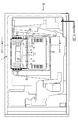
以下、本発明の好ましい実施例について、添付図面を参照して説明する。図1は、本発明の遊技機用基板ボックスユニットの一実施例であるボックスユニット1の分解斜視図であり、図2は、ボックスユニット1の配設された遊技機の一種であるパチンコ機90の裏面の部分断面図である。図3は、図2のIII−III線における平面部分断面図であり、図4は、図2のIV−IV線におけるボックスユニット1を分解した平面断面図である。図5は、図3のV−V線におけるボックスユニット1の裏面部分図である。尚、図3に示す2点鎖線は、連接板8を介してボックスユニット1が回転された状態を図示している。
【0009】
図1に示すように、ボックスユニット1は、遊技機の一種であるパチンコ機90(図2参照)の遊技内容に関する制御プログラムやデータを記憶した制御用ROM等の電子部品(図示せず)が搭載された制御回路基板6を被包して封印するためのものである。このボックスユニット1は、主に、基板ボックス2と、取付部材5とを備え、図2に示すパチンコ機90の遊技盤91の裏面に設けられた入賞球集合カバー92に取り付けられている。
【0010】
図1に示すように、基板ボックス2は、ボックス本体3と、そのボックス本体3に覆設されるボックス蓋体4とを備え、透明な高分子樹脂等で構成されている。このボックス本体3およびボックス蓋体4は、いずれも略矩形皿状に形成されており、制御回路基板6をボックス本体3内に収納した状態で、互いの開口面を対向させ合致(合体)させることにより、制御回路基板6を基板ボックス2内に被包することができる。
【0011】
ボックス本体3の左右両側面には4つの中空円柱状の封印部材31がそれぞれ配設され、ボックス蓋体4の左右両側面には各封印部材31に対応して4つの中空円柱状の封印部材41がそれぞれ配設されている。この各封印部材31,41は制御回路基板6への不正行為を防止するため基板ボックス2を封印する部材であり、ボックス本体3の各封印部材31には封印ねじ71の螺入されるナット部材72と、そのナット部材72に螺入された封印ねじ71を係止する係止座金73とがそれぞれ設置される。尚、封印ねじ71は互いに対向する一対の封印部材31,41内に螺入され両者を連結する部材である。
【0012】
この各封印部材31,41により基板ボックス2を封印する場合、制御回路基板6をボックス本体3内に収納した状態で、ボックス本体3にボックス蓋体4を覆設して、各封印部材31,41を対向させて当接する(図3参照)。各封印部材31,41の当接後、ボックス蓋体4右側面の最後側に配設された封印部材41およびボックス蓋体4左側面の最前側に配設された封印部材41に封印ねじ71をそれぞれ挿入し、これらの封印ねじ71を各封印部材31内に設置されたナット部材72へ螺入し続ける。この封印ねじ71の螺入が完了すると、封印部材31内の係止座金73によって封印ねじ71が抜き取り不可能な状態で係止される。その結果、封印ねじ71により封印部材31と封印部材41とが連結されて、基板ボックス2を封印することができる。尚、図3に示すように、封印部材31の側面部には封印ねじ71と同一種類の予備用封印ねじ74を保持することができる。
【0013】
次に、基板ボックス2のボックス本体3を取付部材5に取り付ける(結合する)ために、ボックス本体3に設けられた各部材について説明する。まず、ボックス本体3の後側面の下方部分には、ボックス本体3の外方へ向けて、2つの略矩形状の突部32が突設されている。これらの突部32は、取付部材5の後側縁部分に穿設された2つの穴部52に挿入可能に形成されており、各突部32を各穴部52に挿入することにより、ボックス本体3の後側面を取付部材5の後側縁部分に係止することができる。また、ボックス本体3の前側面、即ち、各突部32の突設面に対向する側面には矩形状に開口された切欠部33が形成されており、切欠部33の上部端面は取付部材5に形成された2つの係止爪53により係止される。
【0014】
ボックス本体3の底部35の下面、即ち、ボックス本体3の取付部材5側の面には、ボックス本体3の外方へ向けて、略矩形状の係合爪34が突設されている。この係合爪34は、取付部材5の係合穴54に係合可能に形成されており、ボックス本体3および取付部材5が結合された場合に、ボックス本体3の取付部材5に対する相対的なスライドを抑制するためのものである。尚、ボックス本体3と取付部材5との結合方法については後述する。
【0015】
切欠部33は、また、ボックス蓋体4がボックス本体3に覆設された場合に、基板ボックス2の一側壁に導出口21を形成する(図3参照)。よって、その導出口21を介して基板ボックス2内に収納された制御回路基板6の雄型コネクタ61に接続されたアース線62やフラットケーブル63を基板ボックス2から導出させることができる。
【0016】
また、ボックス蓋体4の上面には、基板ボックス2と取付部材5とを結合する場合の基板ボックス2のスライド方向を表示した方向表示42が形成されており、この方向表示42の示す方向へ基板ボックス2をスライドさせることにより、基板ボックス2を取付部材5に結合することができる。尚、この方向表示42は、ボックス蓋体4の成形と同時に型枠を用いて形成される。
【0017】
図5に示すように、ボックス本体3の底部35外面には、基板ボックス2のボックス本体3を取付部材5から取り外すための操作方法を表示した操作表示36が設けられている。例えば、本実施例の操作表示36によれば、「PUSH」の表示と、矢印の表示を有している。この操作表示36の「PUSH」の表示は、基板ボックス2を取付部材5から取り外す場合に、その「PUSH」の表示部分を押圧しなければならない旨を指示している。また、矢印の表示は、基板ボックス2を取付部材5から取り外す場合に、基板ボックス2を矢印の方向へスライドさせなければならない旨を指示している。
【0018】
この操作表示36はボックス本体3の成形と同時に型枠を用いて凸状に形成される。よって、係合爪34および係合穴54の係合状態を解除するため、操作表示36に指を押し当て基板ボックス2をスライドさせる場合、指先が操作表示36に引っかかり指の滑りを防止することができる。
【0019】
次に、図1を参照して、上述した基板ボックス2が結合される取付部材5について説明する。この取付部材5は導電性を有する薄板状の金属材料、例えば、薄板鋼材等で構成されており、ボックス本体3の底部35が嵌合可能な薄皿状の主板51を備えている。この主板51上面の面積は基板ボックス2に収納される制御回路基板6と略同一面積となるように形成されているので、基板ボックス2の外部からの電気的ノイズを確実に除去することができる。また、主板51の縁部分には周囲板56が周設されており、その周囲板56の後側縁部分および主板51に跨った部分には2つの矩形状の穴部52が穿設されている。これらの穴部52は上述したボックス本体3に突設された各突部32に対応して穿設されており、かかる各突部32は各穴部52へ挿入され係止される。取付部材5の前側縁部分に形成された周囲板56の上端部分には、2つの係止爪53が一体形成されている。この各係止爪53は側面視略コ字状に形成されており、各係止爪53内にボックス本体3の切欠部33が填め込まれる(図3参照)。
【0020】
取付部材5の主板51の略中央部分には、矩形状の係合穴54が穿設されており、この係合穴54にボックス本体3に突設された係合爪34が係合されるのである。即ち、この係合穴54に上述した係合爪34が係合させるためには、まず、基板ボックス2を傾けた状態で、基板ボックス2のボックス本体3に突設された各突部32を取付部材5の各穴部52へ挿入した後、ボックス本体3の底部35の下面と取付部材5の主板51の上面とを当接させつつ、ボックス本体3を切欠部33側へとスライドさせる(図4参照)。ボックス本体3のスライドに伴って、ボックス本体3の切欠部33が取付部材5の各係止爪53に係止され、更に、ボックス本体3の底部35の下面の係合爪34が取付部材5の係合穴54に係合される(図3参照)。図3に示すように、係合爪34および係合穴54が係合されると、係合穴54および係合爪34によって、ボックス本体3の矢印D方向へのスライドが抑制されるので、基板ボックス2のボックス本体3と取付部材5とを確実に結合することができる。
【0021】
この係合爪34および係合穴54の係合の解除により、基板ボックス3および取付部材5の結合を解除することができるが、図3に示すように、ボックスユニット1は、通常、ボックスユニット1の係合爪34および係合穴54が遊技盤91や入賞球集合カバー92に対向した状態で、入賞球集合カバー92に取り付けられるので、ボックスユニット1を反転させなければ係合爪34および係合穴54は見ることができない。よって、パチンコ機90の検査等を行う場合に、係合爪34および係合穴54の不用意な操作が防止され、基板ボックス2と取付部材5との結合状態を誤って解除してしまうことを防止することができるのである。
【0022】
図1に示すように、取付部材5の右側端部分に設けられた周囲板56には接続端子55が形成されており、この接続端子55は、雄型コネクタ61等を介して制御回路基板6に接続されたアース線62の一端をネジ止めにより接続することができる。取付部材5の主板51の下面には、後述する連接板8を取付部材5に取り付けるための2つの軸受部57が形成されており、これらの軸受部57には、連接板8の2本の取付ピン81がそれぞれ回動可能に支持される。また、取付部材5の左右縁部分には、下方へ向けて取付片58がそれぞれ形成されている。この各取付片58を入賞球集合カバー92に配設された留め具(図示せず)によって係止することにより、連接板8によるボックスユニット1の回動を防止することができる。
【0023】
図2に示すように、ボックスユニット1の取付部材5の裏面には連接板8が取り付けられている。この連接板8は、正面視長板状に形成されたヒンジ部材であり、4本の取付ピン81を備えている。この各取付ピン81のうち2本の取付ピン81は連接板8の右側端部分に突設されており、その他の2本の取付ピン81は連接板8の左側端部分に突設されている。連接板8の右側端部分(図2中、右側)に突設された2本の取付ピン81は、取付部材5に設けられた2つの軸受部57に回動可能にそれぞれ支持されている。また、連接板8の左側端部分(図2中、左側)に突設される各取付ピン81は、入賞球集合カバー92に突設された各軸受部92aに回動可能にそれぞれ差し込まれる。よって、ボックスユニット1は、連接板8により入賞球集合カバー92に対して回動可能に配設されるのである。
【0024】
尚、連接板8の入賞球集合カバー92の各軸受部92aに差し込まれた各取付ピン81は、それぞれ各軸受部92aに対して着脱可能に形成されているので、ボックスユニット1を入賞球集合カバー92から取り外して検査することもできる。また、連接板8は、遊技盤91の裏面に直に取り付けても良い。
【0025】
図1に示すように、制御回路基板6は、矩形薄板状に形成されており、その一側には5個の雄型コネクタ61が隣接配置されている。このうち、制御回路基板6の右端の雄型コネクタ61には、アース線62の一端に配設された雌型コネクタ62aが嵌合されている。このアース線62の他端は取付部材5の接続端子55にネジ止めにより接続されている。この接続端子55が形成された取付部材5は導電性を有する金属材料(薄板鋼材等)で構成されているので、制御回路基板6に搭載された電子部品の誤動作の原因となる電気的ノイズを除去することができる。また、他の雄型コネクタ61には、フラットケーブル63の一端に配設された雌型コネクタ63aが嵌合される。尚、図1では、制御回路基板6に搭載される各種電子部品の図示を省略し、アース線62およびフラットケーブル63の一部を省略して図示している。また、図1では、図面の簡略化のため、3個の雄型コネクタ61にそれぞれ接続される3つのフラットケーブル63の図示を省略している。
【0026】
制御回路基板6には高分子樹脂等で構成された仕切板65がネジ止めによって取着されている。この仕切板65は制御回路基板6に対して略垂直に取着されており、ボックス本体3とボックス蓋体4とを合体させた場合に、基板ボックス2の内外部を仕切ることができる。よって、基板ボックス2の外部からの制御回路基板6への接触行為を防止することができるのである。また、図1に示すように、仕切板65の制御回路基板6側の端部分には、各雄型コネクタ61に対応して5つの矩形状のコネクタ穴部65aが穿設されている。よって、雄型コネクタ61を回避して仕切板65を制御回路基板6に取着することができる。
【0027】
次に、図3および図4を参照して、基板ボックス2および取付部材5の結合方法について説明する。まず、図4に示すように、制御回路基板6を基板ボックス2により被包した後、基板ボックス2の各突部32を取付部材5の各穴部52へ挿入する。各突部32の挿入後、基板ボックス2を矢印A方向へ回転させて、ボックス本体3の底部35の外面を取付部材5の主板51に当接させる。基板ボックス2と取付部材5との当接後、基板ボックス2を矢印B方向へスライドさせると、基板ボックス2の右側面と取付部材5の右側縁部分の周囲板56とが当接し、各突部32が穴部52に挿入された状態のまま、ボックス本体3の切欠部33が係止爪53に填め込まれて係止される。その結果、基板ボックス2と取付部材5とが結合される(図3参照)。このように、基板ボックス2および取付部材5が結合されると、図3に示すように、ボックス本体3の裏面に突設された係合爪34の左側面が取付部材5の係合穴54の左側面に当接して、係合爪34が係合穴54に係合されるので、基板ボックス2の矢印D方向へのスライドを抑制され、かかる結合が維持される。
【0028】
次に、図3を参照して、基板ボックス2および取付部材5の結合状態の解除方法について説明する。この結合状態を解除する場合には、パチンコ機90の入賞球集合カバー92に配設された留め具(図示せず)によるボックスユニット1の係止を解除した後、係合爪34および係合穴54の係合状態を解除する必要がある。この係合状態の解除は、ボックスユニット1の裏面側、即ち、取付部材5側からボックス本体3の底部35の外面を係合穴54を介して矢印C方向へ押圧しつつ、ボックス本体3を矢印D方向へスライドさせることにより行われる。係合爪34および係合穴54の係合が解除されると、係止爪53による切欠部33の係止が解除される。その後、図4の反矢印A方向へ基板ボックス2を回転させて、各突部32を各穴部52から引き抜くことにより、基板ボックス2が取付部材5から取り外される。
【0029】
しかしながら、図3に示すように、ボックスユニット1は、通常、ボックスユニット1の係合爪34および係合穴54が遊技盤91や入賞球集合カバー92に対向した状態で、入賞球集合カバー92に取り付けられるので、そのままの状態では係合穴54を介してボックス本体3の底部35外面を押圧することができず、係合爪34および係合穴54の係合状態を解除することができない。このため、ボックスユニット1を連接板8を介して反時計方向へ回転させて、図3中の2点鎖線の位置へ移動させた後、係合爪34および係合穴54の係合状態の解除が行われる。
【0030】
このように、係合爪34および係合穴54の係合状態を解除して、基板ボックス2および取付部材5の結合状態を解除するには、ボックスユニット1を連接板8を介して反時計方向へ回転させて、図3中の2点鎖線の位置へ移動させなければならない。よって、パチンコ機90の検査等を行う場合に、係合爪34および係合穴54の係合状態が不用意に解除されることが防止され、基板ボックス2と取付部材5との結合状態を誤って解除してしまうことを防止することができる。
【0031】
また、上述した操作表示36は取付部材5の係合穴54の穿設位置に対応してボックス本体3に形成されているので、基板ボックス2と取付部材5とが結合されても、取付部材5の係合穴54を介して操作表示36を容易に視認することができる。また、基板ボックス2と取付部材5とが結合された場合に、操作表示36、係合爪34および係合穴54は、ボックスユニット1の同一面に形成されているので、操作表示36を参照しつつ、係合爪34および係合穴54の係合解除を行って、ボックス本体3を取付部材5から取り外すことができる。
【0032】
以上、実施例に基づき本発明を説明したが、本発明は上記実施例に何ら限定されるものではなく、本発明の趣旨を逸脱しない範囲内で種々の改良変形が可能であることは容易に推察できるものである。
【0033】
例えば、本実施例では、取付部材5を導電性を有する金属材料である薄板鋼材等で構成した。しかしながら、取付部材5の材質は、必ずしもこれに限られるものではなく、導電性を有する高分子材料等で構成しても良い。即ち、制御回路基板6の動作に悪影響を及ぼす電気的ノイズを除去することができる導電性材料であれば良い。
【0034】
また、本実施例では、手順表示(操作表示36,方向表示42)をボックス本体3またはボックス蓋体4の成形と同時に型枠を用いて形成した。しがしながら、手順表示を付す方法は必ずしもこれに限られるものではなく、操作手順等を印刷した合成樹脂等のシートをボックス本体やボックス蓋体に貼付するようにしても良い。
【0035】
回路基板を被包する遊技機用基板ボックスと、その遊技機用基板ボックスを遊技機の裏側面に回動可能に取り付ける取付部材と、その取付部材および遊技機用基板ボックスを結合させる結合手段とを備え、前記遊技機の裏側面と前記遊技機用基板ボックスまたは取付部材との間に配設され、前記結合手段による前記遊技機用基板ボックスおよび取付部材の結合状態を解除する結合解除手段を備えている遊技機用基板ボックスユニット1。
【0036】
この遊技機用基板ボックスユニット1によれば、取付部材と回路基板を被包した遊技機用基板ボックスとは結合手段によって結合され、その取付部材は遊技機の裏側面に回動可能に取り付けられる。この遊技機用基板ボックスと取付部材との結合状態の解除は結合解除手段を操作することによって行われるが、この結合解除手段は遊技機の裏側面と遊技機用基板ボックスまたは取付部材との間に配設されているので、そのままの状態では結合解除手段を操作することができず、結合状態を解除することができない。よって、かかる結合解除手段を操作するためには、取付部材を回動して、まず結合解除手段を反転させなければならない。即ち、結合解除手段はそのままの状態では操作することができないので、不用意な結合解除手段の操作を防止して、遊技機用基板ボックスと取付部材との結合状態を誤って解除してしまうことを防止することができる。
【0037】
回路基板が配設されるボックスベースとそのボックスベースに被せられるボックスカバーとを有する遊技機用基板ボックスと、その遊技機用基板ボックスを遊技機の裏側面に回動可能に取り付ける取付部材と、その取付部材および遊技機用基板ボックスを結合する結合手段とを備えた遊技機用基板ボックスユニットにおいて、前記遊技機の裏側面と前記ボックスベースとの間に配設される第1係合部と、その第1係合部に対向しつつ前記遊技機の裏面と前記取付部材との間に配設され前記第1係合部に係合される第2係合部とを有する結合解除手段を備え、前記結合手段によって前記遊技機用基板ボックスおよび取付部材を結合することにより、前記結合解除手段の第1係合部および第2係合部が係合されるとともに、その第1係合部および第2係合部の係合を解除することによって、前記結合手段による前記遊技機用基板ボックスおよび取付部材の結合が解除されることを特徴とする遊技機用基板ボックスユニット2。
【0038】
この遊技機用基板ボックスユニット2によれば、回路基板をボックスベースに収納し、そのボックスベースにボックスカバーを被せることにより、回路基板が遊技機用基板ボックス内に収納される。回路基板を収納した後、遊技機用基板ボックスと取付部材とを結合手段によって結合すると、結合解除手段の第1係合部と第2係合部とが係合され、遊技機用基板ボックスと取付部材との結合が完了し、遊技機用基板ボックスが取付部材を介して遊技機の裏側面に回動可能に取り付けられる。この遊技機用基板ボックスおよび取付部材の結合状態を解除する場合、結合解除手段の第1係合部は遊技機の裏側面とボックスベースとの間に配設され、かつ、第2係合部は遊技機の裏側面と取付部材との間に配設されているので、そのままの状態ではこれらを操作することができない。よって、遊技機の検査等を行う場合に、結合解除手段の不用意な操作が防止され、遊技機用基板ボックスと取付部材との結合状態を誤って解除してしまうことを防止することができる。
【0039】
遊技機用基板ボックスユニット1,2または請求項1記載の遊技機用基板ボックスユニットにおいて、回路基板が配設されるボックスベースとそのボックスベースに被せられるボックスカバーとを有する遊技機用基板ボックスと、遊技機の裏側面に対向する前記ボックスベースの壁面に配設される第1係合部とその第1係合部に対向しつつ遊技機の裏面に対向する前記取付部材の壁面に配設され前記第1係合部に係合される第2係合部とを有する結合解除手段とを備え、前記第1係合部は前記遊技機の裏面と対向する前記ボックスべースの壁面に突設された係合爪であり、前記第2係合部は前記係合爪に対向しつつ、前記遊技機の裏面に対向する前記取付部材の壁面に穿設された係合穴であることを特徴とする遊技機用基板ボックスユニット3。
【0040】
遊技機用基板ボックスユニット1から3または請求項1記載の遊技機用基板ボックスユニットにおいて、前記遊技機用基板ボックスまたは取付部材は、前記結合手段による前記遊技機用基板ボックスおよび取付部材の結合手順を指示する結合手順指示手段を備えていることを特徴とする遊技機用基板ボックスユニット4。この遊技機用基板ボックスユニット4によれば、結合手順指示手段による指示に従って、遊技機用基板ボックスと取付部材との結合を容易に行うことができる。
【0041】
遊技機用基板ボックスユニット1から4のいずれか、または、請求項1記載の遊技機用基板ボックスユニットにおいて、前記取付部材に結合された前記遊技機用基板ボックスが遊技機の裏面の所定位置に配置されている状態で、前記遊技機用基板ボックスまたは取付部材のうち前記遊技機の裏側面に対向(対面)する部分には、前記結合解除手段による前記遊技機用基板ボックスおよび取付部材の結合解除手順を指示する解除手順指示手段が設けられていることを特徴とする遊技機用基板ボックスユニット5。この遊技機用基板ボックスユニット5によれば、解除手順指示手段による指示に従って、遊技機用基板ボックスと取付部材との結合状態の解除を容易に行うことができる。また、解除手順指示手段は、取付部材に結合された遊技機用基板ボックスが遊技機の裏面の所定位置に配置されている状態において、遊技機用基板ボックスまたは取付部材のうち遊技機の裏側面に対向(対面)する部分に設けられているので、結合解除手段によって結合状態の解除を行う際に、解除手順指示手段を視認することができる。
【0042】
遊技機用基板ボックスユニット1から5のいずれか、または、請求項1記載の遊技機用基板ボックスユニットにおいて、前記取付部材は導電性材料で形成されるとともに、前記遊技機用基板ボックスに被包される回路基板から配線されたアース線が接続される接続端子を備えていることを特徴とする遊技機用基板ボックスユニット6。この遊技機用基板ボックスユニット6によれば、アース線によって、導電性材料で形成された取付部材と遊技機用基板ボックスに被包された回路基板とが接続されるので、回路基板に悪影響を及ぼす電気的ノイズを取付部材により除去することができる。
【0043】
【発明の効果】
本発明の遊技機によれば、遊技機用基板ボックスおよび取付部材の結合状態は、取付部材に結合された遊技機用基板ボックスが遊技機の裏側面の所定位置に配置されている場合には解除できない。よって、取付部材を介して、まず遊技機用基板ボックスを遊技機の裏側面の所定位置から回動しなければならない。即ち、不用意な結合解除の操作を防止して、遊技機用基板ボックスと取付部材との結合状態を誤って解除してしまうことを防止することができるという効果がある。
【図面の簡単な説明】
【図1】 本発明の遊技機用基板ボックスユニットの一実施例であるボックスユニットの分解斜視図である。
【図2】 ボックスユニットの配設された遊技機の一種であるパチンコ機の裏面の部分断面図である。
【図3】 図2のIII−III線における平面部分断面図である。
【図4】 図2のIV−IV線におけるボックスユニットを分解した平面断面図である。
【図5】 図3のV−V線におけるボックスユニットの裏面部分図である。
【符号の説明】
1 ボックスユニット(遊技機用基板ボックスユニットの一部)
2 基板ボックス(遊技機用基板ボックス)
3 ボックス本体(ボックスベース)
4 ボックス蓋体(ボックスカバー)
5 取付部材(取付部材の一部)
6 制御回路基板(回路基板)
8 連接板(取付部材の一部)
32 突部(結合手段の一部)
33 切欠部(結合手段の一部)
34 係合爪(結合手段の一部、第2係合部)
36 操作表示(解除手順指示手段)
42 方向表示(結合手順指示手段)
52 穴部(結合手段の一部)
53 係止爪(結合手段の一部)
54 係合穴(結合手段の一部、第1係合部)
55 接続端子
65 仕切板
90 パチンコ機(遊技機)[0001]
BACKGROUND OF THE INVENTION
The present invention relates to a gaming machine including a gaming machine board box unit that can prevent the gaming machine board box from being accidentally detached from an attachment member.
[0002]
[Prior art]
In recent years, gaming machines such as pachinko machines and slot machines have become mainstream that control the prize-winning devices and display devices provided on the game board to increase the fun of the game. The winning device and the display device are controlled by a logic control circuit board provided with a large number of electronic components such as IC and LSI, or a control circuit board having a microcomputer. The control circuit board is encapsulated in a gaming machine board box having a box base and a box cover, and the gaming machine board box is coupled to a mounting plate and arranged on the back surface of the gaming board via the mounting plate. It is attached to the winning ball collecting cover or the mechanism plate.
[0003]
By the way, when the gaming machine board box and the mounting plate are coupled, the gaming machine board box needs to be coupled in a detachable state from the mounting board in consideration of maintenance of the gaming machine board box. For this reason, for example, a coupling tool including a lock member and a button member detachably formed on the lock member is used for coupling the conventional gaming machine board box and the mounting plate. In this coupling tool, the button member is engaged with the lock member by pushing the button member provided in the board box for gaming machine into the lock member provided on the mounting plate, and the button member is arranged. The installed gaming machine board box and the mounting plate on which the lock member is disposed are combined.
[0004]
[Problems to be solved by the invention]
However, the coupling tool is exposed and arranged in a state that is visible from the back of the gaming machine, and the coupling state between the gaming machine board box and the mounting member can be easily released by pulling out the button member. Therefore, there is a problem that the board box is inadvertently removed in the inspection of the gaming machine or the like. Also, in a gaming machine in which the winning ball collective cover and the mechanism board are coupled to the back of the game board by the same type of coupler, the game board and the winning ball collective cover and the mechanism board are coupled. When releasing, there was a problem that the board box for gaming machines was accidentally removed from the mounting plate.
[0005]
The present invention has been made to solve the above-described problems, and a gaming machine including a gaming machine board box unit that can prevent the gaming machine board box from being accidentally removed from the mounting member. The purpose is to provide.
[0006]
[Means for Solving the Problems]
In order to achieve this object, a gaming machine according to claim 1 is a gaming machine board box that encloses a circuit board, and a mounting member that rotatably attaches the gaming machine board box to the back side of the gaming machine. A gaming machine substrate box unit having a coupling means for coupling the mounting member and the gaming machine substrate box, the mounting member being formed in a plate-like main plate, and penetrating the main plate. The gaming machine board box has a main body formed in a box shape, and protrudes outward from the main body and has a first engaging portion as the coupling means. A second engagement portion as the coupling means that can be engaged with the first engagement portion of the attachment member when attached to the main plate, and the gaming machine is provided on one side of the main plate of the attachment member. The body of the board box for Vignetting, the main plate the gaming machine board box unit in a state where the opposite side is opposed to the back surface of the gaming machine are mounted on the back surface of the gaming machine, the relative its opposite state First and The attachment member is rotated so that the second engagement portion is separated from the back side surface of the gaming machine. ,in front From the opposite side of the main plate The first engaging portion and Second engaging part Release the engaged state Thus, the gaming machine substrate box is configured to be removable from the mounting member.
[0007]
According to the gaming machine of the first aspect, the mounting member and the gaming machine board box enclosing the circuit board are coupled by the coupling means, and the mounting member is rotatably mounted on the back side surface of the gaming machine. . The coupled state of the gaming machine board box and the mounting member cannot be released when the gaming machine board box coupled to the mounting member is disposed at a predetermined position on the back side surface of the gaming machine. For this reason, the coupled state is released by rotating the gaming machine board box unit from a predetermined position on the back side surface of the gaming machine via the mounting member.
[0008]
DETAILED DESCRIPTION OF THE INVENTION
Hereinafter, preferred embodiments of the present invention will be described with reference to the accompanying drawings. FIG. 1 is an exploded perspective view of a box unit 1 which is an embodiment of a board box unit for gaming machines of the present invention, and FIG. 2 is a
[0009]
As shown in FIG. 1, the box unit 1 includes electronic components (not shown) such as a control ROM storing control programs and data related to game contents of a pachinko machine 90 (see FIG. 2) which is a kind of gaming machine. This is for encapsulating and sealing the mounted
[0010]
As shown in FIG. 1, the
[0011]
Four hollow
[0012]
When the
[0013]
Next, each member provided in the box body 3 in order to attach (join) the box body 3 of the
[0014]
A substantially rectangular engaging
[0015]
The
[0016]
Further, on the upper surface of the box lid 4, a direction display 42 indicating the sliding direction of the
[0017]
As shown in FIG. 5, an
[0018]
The
[0019]
Next, the mounting
[0020]
A
[0021]
By releasing the engagement between the
[0022]
As shown in FIG. 1, a
[0023]
As shown in FIG. 2, a connecting
[0024]
The mounting pins 81 inserted into the bearing
[0025]
As shown in FIG. 1, the
[0026]
A
[0027]
Next, with reference to FIG. 3 and FIG. 4, a method of joining the
[0028]
Next, with reference to FIG. 3, the cancellation | release method of the combined state of the board |
[0029]
However, as shown in FIG. 3, the box unit 1 usually has the winning
[0030]
Thus, in order to release the engagement state of the
[0031]
Further, since the
[0032]
The present invention has been described above based on the embodiments. However, the present invention is not limited to the above embodiments, and various modifications can be easily made without departing from the spirit of the present invention. It can be guessed.
[0033]
For example, in the present embodiment, the
[0034]
Further, in this embodiment, the procedure display (
[0035]
A gaming machine board box that encloses the circuit board, a mounting member that pivotably attaches the gaming machine board box to the back side of the gaming machine, and a coupling means that couples the mounting member and the gaming machine board box. A coupling release means disposed between a back side surface of the gaming machine and the gaming machine board box or the mounting member, and for releasing the coupled state of the gaming machine board box and the mounting member by the coupling means. A gaming machine board box unit 1 provided.
[0036]
According to the gaming machine board box unit 1, the mounting member and the gaming machine board box enclosing the circuit board are coupled by the coupling means, and the mounting member is pivotally mounted on the back side surface of the gaming machine. . The coupled state between the gaming machine board box and the mounting member is released by operating the coupling releasing means. The coupling releasing means is provided between the back side of the gaming machine and the gaming machine board box or mounting member. Therefore, the coupling release means cannot be operated in the state as it is, and the coupled state cannot be released. Therefore, in order to operate such a coupling release means, it is necessary to first rotate the attachment member to reverse the coupling release means. That is, since the uncoupling means cannot be operated as it is, the unintentional operation of the uncoupling means is prevented, and the coupling state between the gaming machine board box and the mounting member is erroneously released. Can be prevented.
[0037]
A gaming machine board box having a box base on which a circuit board is disposed and a box cover that covers the box base, and a mounting member that rotatably attaches the gaming machine board box to the back side surface of the gaming machine; A gaming machine board box unit comprising the mounting member and a coupling means for coupling the gaming machine board box, a first engagement portion disposed between a back side surface of the gaming machine and the box base; A decoupling means having a second engaging portion disposed between the back surface of the gaming machine and the mounting member and being engaged with the first engaging portion while facing the first engaging portion. A first engagement portion and a second engagement portion of the coupling release means are engaged by coupling the gaming machine board box and the attachment member by the coupling means, and the first engagement portion and By releasing the engagement of the second engaging portion, said coupling means according to the game machine board boxes and mounting for gaming machines substrate box unit, characterized in that the coupling is released
[0038]
According to the gaming machine
[0039]
2. A gaming machine board box unit according to claim 1, wherein the gaming machine board box unit has a box base on which a circuit board is disposed and a box cover that covers the box base. A first engaging portion disposed on the wall surface of the box base facing the back side surface of the gaming machine and a wall surface of the mounting member facing the back surface of the gaming machine while facing the first engaging portion. And a coupling release means having a second engagement portion engaged with the first engagement portion, wherein the first engagement portion is formed on a wall surface of the box base facing a back surface of the gaming machine. It is a projecting engaging claw, and the second engaging portion is an engaging hole formed in the wall surface of the mounting member facing the back surface of the gaming machine while facing the engaging claw. Board box unit for gaming machines characterized by .
[0040]
The gaming machine board box unit or the mounting member according to claim 1, wherein the gaming machine board box or the mounting member is a coupling procedure of the gaming machine board box and the mounting member by the coupling means. A board box unit 4 for gaming machines, comprising a coupling procedure instruction means for instructing. According to the gaming machine board box unit 4, the gaming machine board box and the attachment member can be easily coupled in accordance with an instruction from the coupling procedure instruction means.
[0041]
The gaming machine board box unit according to any one of the gaming machine board box units 1 to 4 or the gaming machine board box unit according to claim 1, wherein the gaming machine board box coupled to the mounting member is located at a predetermined position on the back surface of the gaming machine. The gaming machine board box and the mounting member are coupled to the gaming machine board box and the mounting member on the portion of the gaming machine board box or mounting member facing (facing) the back side surface of the gaming machine. A
[0042]
2. The gaming machine board box unit according to claim 1, or the gaming machine board box unit according to claim 1, wherein the mounting member is formed of a conductive material and is encapsulated in the gaming machine board box. A
[0043]
【The invention's effect】
According to the gaming machine of the present invention, when the gaming machine board box and the mounting member are coupled to each other, the gaming machine board box coupled to the mounting member is disposed at a predetermined position on the back side surface of the gaming machine. Cannot be released. Therefore, the board box for gaming machines must first be rotated from a predetermined position on the back side surface of the gaming machine via the mounting member. That is, there is an effect that it is possible to prevent an inadvertent release operation of the coupling and prevent the gaming machine board box and the mounting member from being erroneously released.
[Brief description of the drawings]
FIG. 1 is an exploded perspective view of a box unit which is an embodiment of a board box unit for gaming machines of the present invention.
FIG. 2 is a partial cross-sectional view of the back surface of a pachinko machine that is a type of gaming machine in which box units are arranged.
3 is a partial plan sectional view taken along line III-III in FIG. 2;
4 is an exploded plan sectional view taken along the line IV-IV in FIG. 2; FIG.
5 is a partial back view of the box unit taken along line VV in FIG. 3; FIG.
[Explanation of symbols]
1 Box unit (part of board box unit for gaming machines)
2 Board box (Board box for gaming machines)
3 Box body (box base)
4 Box cover (box cover)
5 Mounting member (part of mounting member)
6 Control circuit board (circuit board)
8 Connecting plate (part of mounting member)
32 Projection (part of coupling means)
33 Notch (part of coupling means)
34 engaging claw (part of coupling means, second engaging portion)
36 Operation display (release procedure instruction means)
42 Direction display (joining procedure instruction means)
52 hole (part of coupling means)
53 Locking claw (part of coupling means)
54 engaging hole (part of coupling means, first engaging portion)
55 Connection terminal
65 divider
90 Pachinko machines (game machines)
Claims (1)
前記取付部材は、板状に形成された主板と、その主板に貫通して形成される前記結合手段としての第1係合部を有する一方、
前記遊技機用基板ボックスは、箱状に形成された本体と、その本体より外方へ向けて突設されると共に前記取付部材の主板に重ねて取り付けられる場合に前記取付部材の第1係合部に係合可能な前記結合手段としての第2係合部とを有し、
前記取付部材の主板の片面側には前記遊技機用基板ボックスの本体が取り付けられ、その主板の反対面側が前記遊技機の裏側面に対向した状態で前記遊技機用基板ボックスユニットが前記遊技機の裏側面に取り付けられ、
その対向状態に対して前記第1および第2係合部が遊技機の裏側面から離間するように前記取付部材を回動し、前記主板の前記反対面側から前記第1係合部および第2係合部の係合状態を解除することによって、前記遊技機用基板ボックスを前記取付部材より取り外し可能に構成されていることを特徴とする遊技機。A gaming machine board box that encloses the circuit board, a mounting member that pivotably attaches the gaming machine board box to the back side of the gaming machine, and a coupling means that couples the mounting member and the gaming machine board box. In a gaming machine equipped with a board box unit for gaming machines having
While the attachment member has a main plate formed in a plate shape and a first engagement portion as the coupling means formed to penetrate the main plate,
The gaming machine substrate box has a box-shaped main body and a first engagement of the mounting member when projecting outward from the main body and mounted on the main plate of the mounting member. A second engaging portion as the coupling means engageable with the portion,
A main body of the gaming machine board box is attached to one side of the main plate of the mounting member, and the gaming machine board box unit is connected to the gaming machine with the opposite side of the main board facing the back side of the gaming machine. Attached to the back side of
Said first and second engagement portions to pivot the mounting member so as to be separated from the back surface of the gaming machine, before Symbol main plate said first engaging portion and from the opposite surface side with respect to its opposite state A gaming machine, wherein the gaming machine board box is configured to be removable from the mounting member by releasing the engaged state of the second engaging portion.
Priority Applications (1)
| Application Number | Priority Date | Filing Date | Title |
|---|---|---|---|
| JP28007897A JP3832048B2 (en) | 1997-10-14 | 1997-10-14 | Game machine |
Applications Claiming Priority (1)
| Application Number | Priority Date | Filing Date | Title |
|---|---|---|---|
| JP28007897A JP3832048B2 (en) | 1997-10-14 | 1997-10-14 | Game machine |
Related Child Applications (3)
| Application Number | Title | Priority Date | Filing Date |
|---|---|---|---|
| JP2002130335A Division JP3915589B2 (en) | 2002-05-02 | 2002-05-02 | Game machine |
| JP2006021674A Division JP3832506B2 (en) | 2006-01-31 | 2006-01-31 | Game machine |
| JP2006021675A Division JP3832507B2 (en) | 2006-01-31 | 2006-01-31 | Game machine |
Publications (2)
| Publication Number | Publication Date |
|---|---|
| JPH11114185A JPH11114185A (en) | 1999-04-27 |
| JP3832048B2 true JP3832048B2 (en) | 2006-10-11 |
Family
ID=17620010
Family Applications (1)
| Application Number | Title | Priority Date | Filing Date |
|---|---|---|---|
| JP28007897A Expired - Fee Related JP3832048B2 (en) | 1997-10-14 | 1997-10-14 | Game machine |
Country Status (1)
| Country | Link |
|---|---|
| JP (1) | JP3832048B2 (en) |
Families Citing this family (43)
| Publication number | Priority date | Publication date | Assignee | Title |
|---|---|---|---|---|
| JP3986228B2 (en) * | 1999-12-28 | 2007-10-03 | 株式会社ソフィア | Game machine |
| JP2002191827A (en) * | 2001-12-14 | 2002-07-10 | Taiyo Elec Co Ltd | Game machine |
| JP3915589B2 (en) * | 2002-05-02 | 2007-05-16 | 株式会社三洋物産 | Game machine |
| JP2005111026A (en) * | 2003-10-09 | 2005-04-28 | Sanyo Product Co Ltd | Game machine |
| JP4492097B2 (en) * | 2003-11-11 | 2010-06-30 | 株式会社三洋物産 | Game machine |
| JP4492096B2 (en) * | 2003-11-11 | 2010-06-30 | 株式会社三洋物産 | Game machine |
| JP4608879B2 (en) * | 2003-12-10 | 2011-01-12 | 株式会社三洋物産 | Game machine |
| JP4608878B2 (en) * | 2003-12-10 | 2011-01-12 | 株式会社三洋物産 | Game machine |
| JP4662254B2 (en) * | 2005-07-14 | 2011-03-30 | サミー株式会社 | Game machine |
| JP2007089867A (en) * | 2005-09-29 | 2007-04-12 | Daiichi Shokai Co Ltd | Game machine |
| JP4441491B2 (en) * | 2006-01-20 | 2010-03-31 | 株式会社藤商事 | Game machine |
| JP4609447B2 (en) * | 2007-04-05 | 2011-01-12 | 株式会社三洋物産 | Game machine |
| JP4609549B2 (en) * | 2008-08-20 | 2011-01-12 | 株式会社三洋物産 | Game machine |
| JP2010046550A (en) * | 2009-12-03 | 2010-03-04 | Sanyo Product Co Ltd | Game machine |
| JP2010046551A (en) * | 2009-12-03 | 2010-03-04 | Sanyo Product Co Ltd | Game machine |
| JP4835760B2 (en) * | 2010-03-03 | 2011-12-14 | 株式会社三洋物産 | Game machine |
| JP2010115556A (en) * | 2010-03-03 | 2010-05-27 | Sanyo Product Co Ltd | Game machine |
| JP2010115557A (en) * | 2010-03-03 | 2010-05-27 | Sanyo Product Co Ltd | Game machine |
| JP4835762B2 (en) * | 2010-04-02 | 2011-12-14 | 株式会社三洋物産 | Game machine |
| JP2010227624A (en) * | 2010-07-12 | 2010-10-14 | Sanyo Product Co Ltd | Game machine |
| JP2011019929A (en) * | 2010-09-27 | 2011-02-03 | Sanyo Product Co Ltd | Game machine |
| JP2011156437A (en) * | 2011-05-27 | 2011-08-18 | Sanyo Product Co Ltd | Game machine |
| JP2012050861A (en) * | 2011-11-09 | 2012-03-15 | Sanyo Product Co Ltd | Game machine |
| JP2012024634A (en) * | 2011-11-09 | 2012-02-09 | Sanyo Product Co Ltd | Game machine |
| JP5533899B2 (en) * | 2012-01-25 | 2014-06-25 | 株式会社三洋物産 | Game machine |
| JP5533900B2 (en) * | 2012-01-25 | 2014-06-25 | 株式会社三洋物産 | Game machine |
| JP5435071B2 (en) * | 2012-05-02 | 2014-03-05 | 株式会社三洋物産 | Game machine |
| JP5435070B2 (en) * | 2012-05-02 | 2014-03-05 | 株式会社三洋物産 | Game machine |
| JP5561341B2 (en) * | 2012-10-24 | 2014-07-30 | 株式会社三洋物産 | Game machine |
| JP5573972B2 (en) * | 2013-01-16 | 2014-08-20 | 株式会社三洋物産 | Game machine |
| JP5708840B2 (en) * | 2014-02-14 | 2015-04-30 | 株式会社三洋物産 | Game machine |
| JP5708841B2 (en) * | 2014-02-14 | 2015-04-30 | 株式会社三洋物産 | Game machine |
| JP2014230992A (en) * | 2014-08-22 | 2014-12-11 | 株式会社三洋物産 | Game machine |
| JP2014230991A (en) * | 2014-08-22 | 2014-12-11 | 株式会社三洋物産 | Game machine |
| JP2014230990A (en) * | 2014-08-22 | 2014-12-11 | 株式会社三洋物産 | Game machine |
| JP6168099B2 (en) * | 2015-05-15 | 2017-07-26 | 株式会社三洋物産 | Game machine |
| JP2016153011A (en) * | 2016-05-30 | 2016-08-25 | 株式会社三洋物産 | Game machine |
| JP2016154949A (en) * | 2016-06-06 | 2016-09-01 | 株式会社三洋物産 | Game machine |
| JP2016154948A (en) * | 2016-06-06 | 2016-09-01 | 株式会社三洋物産 | Game machine |
| JP6544423B2 (en) * | 2017-12-22 | 2019-07-17 | 株式会社三洋物産 | Gaming machine |
| JP6614269B2 (en) * | 2018-04-13 | 2019-12-04 | 株式会社三洋物産 | Game machine |
| JP6614270B2 (en) * | 2018-04-13 | 2019-12-04 | 株式会社三洋物産 | Game machine |
| JP6845594B1 (en) * | 2020-05-26 | 2021-03-17 | 山佐株式会社 | Game machine |
-
1997
- 1997-10-14 JP JP28007897A patent/JP3832048B2/en not_active Expired - Fee Related
Also Published As
| Publication number | Publication date |
|---|---|
| JPH11114185A (en) | 1999-04-27 |
Similar Documents
| Publication | Publication Date | Title |
|---|---|---|
| JP3832048B2 (en) | Game machine | |
| JP3915589B2 (en) | Game machine | |
| JP3658366B2 (en) | Game machine | |
| JP4520020B2 (en) | Case for circuit board of game machine | |
| JPH10249022A (en) | Circuit board box for game machine | |
| US7553178B1 (en) | Socket connector with pre-assembled screw | |
| JP2508447B2 (en) | Battery device | |
| JP2003325911A (en) | Pullout limiter for connecter | |
| JP3832507B2 (en) | Game machine | |
| JP3959802B2 (en) | Game machine | |
| JP3832506B2 (en) | Game machine | |
| JP3976067B2 (en) | Game machine | |
| JP4087153B2 (en) | Mechanism for preventing unauthorized opening of circuit board case | |
| JPH0924146A (en) | Structure for installing integrated circuit board unit of game machine | |
| JP3960123B2 (en) | Game machine | |
| JP2005342406A (en) | Game machine | |
| JPH09713A (en) | Game machine | |
| JP4125539B2 (en) | Connector pull-out restriction device | |
| JP4166441B2 (en) | Control board storage case for gaming machine | |
| JP4363869B2 (en) | Game machine | |
| JP2003210700A (en) | Game machine | |
| JPH10322038A (en) | Electrical equipment | |
| JPH08203646A (en) | Universal connector | |
| JP4870175B2 (en) | Game machine | |
| JP5222382B2 (en) | Game machine |
Legal Events
| Date | Code | Title | Description |
|---|---|---|---|
| A521 | Written amendment |
Free format text: JAPANESE INTERMEDIATE CODE: A523 Effective date: 20040930 |
|
| A621 | Written request for application examination |
Free format text: JAPANESE INTERMEDIATE CODE: A621 Effective date: 20040930 |
|
| A977 | Report on retrieval |
Free format text: JAPANESE INTERMEDIATE CODE: A971007 Effective date: 20050805 |
|
| A131 | Notification of reasons for refusal |
Free format text: JAPANESE INTERMEDIATE CODE: A131 Effective date: 20051213 |
|
| A521 | Written amendment |
Free format text: JAPANESE INTERMEDIATE CODE: A523 Effective date: 20060131 |
|
| TRDD | Decision of grant or rejection written | ||
| A01 | Written decision to grant a patent or to grant a registration (utility model) |
Free format text: JAPANESE INTERMEDIATE CODE: A01 Effective date: 20060627 |
|
| A61 | First payment of annual fees (during grant procedure) |
Free format text: JAPANESE INTERMEDIATE CODE: A61 Effective date: 20060710 |
|
| R150 | Certificate of patent or registration of utility model |
Free format text: JAPANESE INTERMEDIATE CODE: R150 |
|
| FPAY | Renewal fee payment (event date is renewal date of database) |
Free format text: PAYMENT UNTIL: 20090728 Year of fee payment: 3 |
|
| FPAY | Renewal fee payment (event date is renewal date of database) |
Free format text: PAYMENT UNTIL: 20120728 Year of fee payment: 6 |
|
| FPAY | Renewal fee payment (event date is renewal date of database) |
Free format text: PAYMENT UNTIL: 20150728 Year of fee payment: 9 |
|
| R250 | Receipt of annual fees |
Free format text: JAPANESE INTERMEDIATE CODE: R250 |
|
| R250 | Receipt of annual fees |
Free format text: JAPANESE INTERMEDIATE CODE: R250 |
|
| LAPS | Cancellation because of no payment of annual fees |