JP3824649B2 - Pen syringe with cartridge loading mechanism - Google Patents
Pen syringe with cartridge loading mechanism Download PDFInfo
- Publication number
- JP3824649B2 JP3824649B2 JP51278297A JP51278297A JP3824649B2 JP 3824649 B2 JP3824649 B2 JP 3824649B2 JP 51278297 A JP51278297 A JP 51278297A JP 51278297 A JP51278297 A JP 51278297A JP 3824649 B2 JP3824649 B2 JP 3824649B2
- Authority
- JP
- Japan
- Prior art keywords
- lead screw
- pen
- cartridge holder
- holder assembly
- assembly
- Prior art date
- Legal status (The legal status is an assumption and is not a legal conclusion. Google has not performed a legal analysis and makes no representation as to the accuracy of the status listed.)
- Expired - Fee Related
Links
Images


Classifications
-
- A—HUMAN NECESSITIES
- A61—MEDICAL OR VETERINARY SCIENCE; HYGIENE
- A61M—DEVICES FOR INTRODUCING MEDIA INTO, OR ONTO, THE BODY; DEVICES FOR TRANSDUCING BODY MEDIA OR FOR TAKING MEDIA FROM THE BODY; DEVICES FOR PRODUCING OR ENDING SLEEP OR STUPOR
- A61M5/00—Devices for bringing media into the body in a subcutaneous, intra-vascular or intramuscular way; Accessories therefor, e.g. filling or cleaning devices, arm-rests
- A61M5/178—Syringes
- A61M5/31—Details
- A61M5/315—Pistons; Piston-rods; Guiding, blocking or restricting the movement of the rod or piston; Appliances on the rod for facilitating dosing ; Dosing mechanisms
- A61M5/31565—Administration mechanisms, i.e. constructional features, modes of administering a dose
- A61M5/31576—Constructional features or modes of drive mechanisms for piston rods
- A61M5/31583—Constructional features or modes of drive mechanisms for piston rods based on rotational translation, i.e. movement of piston rod is caused by relative rotation between the user activated actuator and the piston rod
- A61M5/31585—Constructional features or modes of drive mechanisms for piston rods based on rotational translation, i.e. movement of piston rod is caused by relative rotation between the user activated actuator and the piston rod performed by axially moving actuator, e.g. an injection button
-
- A—HUMAN NECESSITIES
- A61—MEDICAL OR VETERINARY SCIENCE; HYGIENE
- A61M—DEVICES FOR INTRODUCING MEDIA INTO, OR ONTO, THE BODY; DEVICES FOR TRANSDUCING BODY MEDIA OR FOR TAKING MEDIA FROM THE BODY; DEVICES FOR PRODUCING OR ENDING SLEEP OR STUPOR
- A61M5/00—Devices for bringing media into the body in a subcutaneous, intra-vascular or intramuscular way; Accessories therefor, e.g. filling or cleaning devices, arm-rests
- A61M5/178—Syringes
- A61M5/31—Details
- A61M5/3146—Priming, e.g. purging, reducing backlash or clearance
-
- A—HUMAN NECESSITIES
- A61—MEDICAL OR VETERINARY SCIENCE; HYGIENE
- A61M—DEVICES FOR INTRODUCING MEDIA INTO, OR ONTO, THE BODY; DEVICES FOR TRANSDUCING BODY MEDIA OR FOR TAKING MEDIA FROM THE BODY; DEVICES FOR PRODUCING OR ENDING SLEEP OR STUPOR
- A61M5/00—Devices for bringing media into the body in a subcutaneous, intra-vascular or intramuscular way; Accessories therefor, e.g. filling or cleaning devices, arm-rests
- A61M5/178—Syringes
- A61M5/31—Details
- A61M5/315—Pistons; Piston-rods; Guiding, blocking or restricting the movement of the rod or piston; Appliances on the rod for facilitating dosing ; Dosing mechanisms
- A61M5/31533—Dosing mechanisms, i.e. setting a dose
- A61M5/31545—Setting modes for dosing
- A61M5/31548—Mechanically operated dose setting member
- A61M5/3155—Mechanically operated dose setting member by rotational movement of dose setting member, e.g. during setting or filling of a syringe
- A61M5/31551—Mechanically operated dose setting member by rotational movement of dose setting member, e.g. during setting or filling of a syringe including axial movement of dose setting member
-
- A—HUMAN NECESSITIES
- A61—MEDICAL OR VETERINARY SCIENCE; HYGIENE
- A61M—DEVICES FOR INTRODUCING MEDIA INTO, OR ONTO, THE BODY; DEVICES FOR TRANSDUCING BODY MEDIA OR FOR TAKING MEDIA FROM THE BODY; DEVICES FOR PRODUCING OR ENDING SLEEP OR STUPOR
- A61M5/00—Devices for bringing media into the body in a subcutaneous, intra-vascular or intramuscular way; Accessories therefor, e.g. filling or cleaning devices, arm-rests
- A61M5/178—Syringes
- A61M5/24—Ampoule syringes, i.e. syringes with needle for use in combination with replaceable ampoules or carpules, e.g. automatic
-
- A—HUMAN NECESSITIES
- A61—MEDICAL OR VETERINARY SCIENCE; HYGIENE
- A61M—DEVICES FOR INTRODUCING MEDIA INTO, OR ONTO, THE BODY; DEVICES FOR TRANSDUCING BODY MEDIA OR FOR TAKING MEDIA FROM THE BODY; DEVICES FOR PRODUCING OR ENDING SLEEP OR STUPOR
- A61M5/00—Devices for bringing media into the body in a subcutaneous, intra-vascular or intramuscular way; Accessories therefor, e.g. filling or cleaning devices, arm-rests
- A61M5/178—Syringes
- A61M5/31—Details
- A61M5/315—Pistons; Piston-rods; Guiding, blocking or restricting the movement of the rod or piston; Appliances on the rod for facilitating dosing ; Dosing mechanisms
- A61M5/31533—Dosing mechanisms, i.e. setting a dose
- A61M5/31535—Means improving security or handling thereof, e.g. blocking means, means preventing insufficient dosing, means allowing correction of overset dose
- A61M5/31543—Means improving security or handling thereof, e.g. blocking means, means preventing insufficient dosing, means allowing correction of overset dose piston rod reset means, i.e. means for causing or facilitating retraction of piston rod to its starting position during cartridge change
Abstract
Description
発明の背景
1.発明の分野
本発明は、カートリッジホルダーアセンブリと、薬品の選ばれた用量を供給するためにカートリッジホルダーアセンブリに取り外し自在に取付けられるペン本体アセンブリとを有する薬品供給ペンの改良されたカートリッジ装填および注入機構に関するものである。
2.関連技術の説明
皮下注射器は薬品の選ばれた用量を患者に供給するよう用いられる。従来の皮下注射器は、対向する基端部と末端部を有する注射器バレルを有している。円筒状の室壁が両端部間に延びていて、流体受容室を形成している。従来の注射器バレルの基端部は大体開口しており、プランジャーを滑動水密係合状態に受けている。従来の注射器バレルの末端部は室と連通する通路を有している。注射針カニューレが従来の注射器バレルの末端部に取付けられて、注射針カニューレの内腔が通路と注射器バレルの室とに連通するようにされている。基端部方向へのプランジャの動きは、注射針カニューレの内腔を通って室内に流体を引き入れる。基端部−末端部方向へのプランジャーの動きは室から注射針カニューレの内腔を通って流体を押圧する。
従来の皮下注射器で注射されるべき薬品は、穿孔可能な弾性シールを有するガラス瓶内にしばしば貯蔵されており、注射針カニューレによって弾性シールを穿孔することにより利用できる。薬品の選ばれた用量は、基端部方向に選ばれた距離だけプランジャーを動かすことによって注射器バレルの室内に引き入れることができる。次いで、注射針カニューレがガラス瓶から引き抜かれ、プランジャーを末端部方向に動かすことによって薬品が患者に注射される。
インシュリンのようなある種の薬品は自分で処理される。一般的な糖尿病患者は一日の内に何回もインシュリンの注射が必要である。インシュリンの必要な用量は患者毎に異なり、各患者毎に一日の間に、かつ日毎に変わることがある。各糖尿病患者は、患者の薬品状態と患者の生活状況とに適合した摂生を達成しよう。摂生は、遅く或いは中間的に作用するインシュリンと迅速に作用するインシュリンとの或る組合せを一般的に有する。各摂生は、仕事場やレストラン等のような公共の場所で糖尿病患者がインシュリンを定期的に自分で処理するよう必要とされることがある。標準の従来の皮下注射とガラス瓶の必要な操作は、このような公共の環境では不都合で、当惑してしまう。
薬品供給ペンは薬品の自己処理を容易にするよう開発されている。1つの従来の薬品供給ペンは、インシュリンや他の薬品のガラス瓶を収容できるガラス瓶ホルダーを有する。ガラス瓶ホルダーは、基端部と末端部を有する細長いほぼ管状の構造である。従来のガラス瓶の末端部は、両頭注射針カニューレと係合する取付手段を有する。また、基端部は以下に更に説明されるように駆動部および投薬設定装置と係合する取付手段を有する。従来のガラス瓶ホルダーと一緒に用いられる使い捨て可能なガラス瓶は、両頭注射針カニューレの一端部によって穿孔できる穿孔可能な弾性シールを有する末端部を有している。この従来のガラス瓶の末端部は、ガラス瓶の円筒状壁と水密係合状態に滑動可能に設けられたプランジャーを有している。この従来の薬品供給ペンは、ガラス瓶ホルダー内に薬品のガラス瓶を挿入することによって使用される。従来のペン本体はそこでガラス瓶ホルダーの末端部に連結される。ペン本体は、ペンにより供給されるべき薬品の投薬を決める投薬設定装置と、選ばれた投薬に対応する距離だけ末端部方向にガラス瓶のプランジャーを押圧する駆動装置とを有している。
ペンの使用者はガラス瓶ホルダーの末端部に従来の両頭注射針カニューレを取付けて、注射針カニューレの基端部がガラス瓶の弾性シールを穿孔するように為す。次いで、患者は用量を選び、ペンを操作してプランジャーを末端方向に押圧して選んだ用量を供給する。用量選択装置は、この従来の薬品供給ペンによる選ばれた用量の注射で零に戻る。そこで、患者は注射針カニューレを取り外して破棄して、次の必要な薬品処理のために適宜な場所に従来の薬品供給ペンを保持する。ガラス瓶内の薬品は数回の薬品のこのような処理の後に排出されよう。患者は、そこでガラス瓶ホルダーをペン本体から取り外す。空のガラス瓶はそこで取り外して破棄できる。新しいガラス瓶がガラス瓶ホルダー内に差し込まれて、ガラス瓶ホルダーとペン本体が上記に説明したように再度組み立てられて使用できる。
上述した再使用可能な薬品供給ペンは、一般的な皮下注射器および分離薬品ガラス瓶よりも薬品の自己処理のために効果的で、かつ一層便利である。しかしながら、空の薬品ガラス瓶を取り外して新しい薬品ガラス瓶を挿入するようペンを分解するのは不便である。その結果、使い捨てペンが開発されている。従来の使い捨て薬品供給ペンは、中に恒久的に収納されたインシュリンや他の薬品等のガラス瓶を有する。患者は薬品の夫々の処理のために両頭注射針カニューレを使い捨てペンに単に接続することが必要である。従来の使い捨てペンは、中に恒久的に収容されていた薬品の供給が行われた時に破棄できる。
使い捨て薬品供給ペンは、薬品を自己処理するよう必要とされる患者にはしばしば便宜である。しかしながら、従来の薬品供給ペンの用量選択駆動機構は実際に複雑な装置であり、製造が高価に付く。従って、実質的な費用の負担が、使い捨て薬品供給ペンの使用の便宜さに関連してくる。
上述した薬品供給ペンによる別の問題は、ペンを充填し、注入することである。これらのペンはリードねじおよび合致するナットの組を一般に用いており、ペンまたはカートリッジから薬品を放出するよう必要とされる線形リードねじに回転用量設定運動を伝達する。このような機構において、ナットは薬品供給の際に回転することが許されるが、リードねじの回転はリードねじに延びているタブを有する強固に取付けられたリングによって阻止されている。従って、ナットが予め選ばれた量だけ回転する時に、ナットとリードねじにおけるねじは、薬品を供給するようリードねじを軸線方向に動かすようになす。次いで、カートリッジが空になって取り換えられなければならない時に、十分に延びたリードねじは手動で回転され、出発位置に戻されて新しいカートリッジを受けるようにされなければならない。しかしながら、リードねじの手動回転は、タブ付リングがリードねじの回転を阻止するよう意図されているので、非常に難しい。
発明の要約
本発明の目的は、患者がペンを容易に充填および注入できる改良されたカートリッジ装填および注入機構を有する薬品供給ペンを提供することによって、従来のペンに見られるカートリッジ装填の際のペンへのリードねじの戻り動きによる問題を解決することにある。本発明はカートリッジ装填の際にペンに容易に滑り戻されるリードねじを有するペンを提供して、これによって患者が回転防止タブ付リングを操作する必要を除去している。本発明において、リードねじは、カートリッジホルダーアセンブリがペンハウジングに十分に螺着される迄、滑動を停止し、このために、螺着作動中のペンの自動注入を設けてリードねじが駆動機構と自動的に係合するようなる。
特に、本発明の薬品供給ペンは、ペン本体アセンブリと選択的に係合および離脱可能になった薬品カートリッジホルダーアセンブリを有する。特に、薬品供給ペンは、リードねじがカートリッジ内のプランジャと接触した時に、カートリッジアセンブリがペン本体アセンブリに到達するように、薬品供給ペンを自動的にかつ容易に滑動して注入するよう薬品供給ペンのリードねじを許す装置を有している。また、薬品供給ペンは、カートリッジがペン本体アセンブリに螺着されるようリードねじをカートリッジホルダーに係合する装置と、カートリッジホルダーアセンブリがペン本体アセンブリに十分に螺着される時にリードねじを駆動機構に係合する装置とを有する。
本発明のこれらおよび他の概念と特徴および利点が添付図面に関連して行われる以下の詳細な説明から明らかになろう。
図面の説明
図1は、本発明の薬品供給ペンの斜視図である。
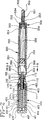
図2は、図1に示される組立てられていない薬品供給ペンの2−2線に沿った斜視図である。
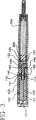
図3は、図2に示される組立てられた薬品供給ペンの長手方向断面図である。
図4は、図1に示される薬品供給ペンの分解された斜視図である。および、
図5は図2に示される薬品供給ペンの5−5線に沿った断面図である。
詳細な説明
本発明に従った投薬供給ペンは図1乃至図4に符号10により概略的に示されている。図1乃至図4に示されるように、薬品供給ペン10は再使用可能なペン本体アセンブリ100、キャップ200、カートリッジホルダーアセンブリ300、注射針カニューレアセンブリ500を有している。カートリッジホルダーアセンブリ300は対向した基端部301、末端部302を夫々有している。カートリッジホルダーアセンブリ300の基端部301は、後に更に説明されるように、ペン本体アセンブリ100に螺着するよう寸法付けられ、かつ形成されている。カートリッジホルダーアセンブリ300の末端部302は、注射針カニューレアセンブリ500に固着されているが、取り外し可能に係合されるよう形成されている。
再使用可能なペン本体アセンブリ100の推奨実施例が図2乃至図4に詳しく図示されている。しかしながら、この推奨実施例の変形例が構成でき、本発明の範囲内にあるべく考慮されることが理解される。再使用可能なペン本体アセンブリ100は、対向する基端部102と末端部103を有するほぼ円筒状のハウジング101を有する。外ねじ105の列が末端部103から基端部方向に延びていて、カートリッジホルダーアセンブリ300の基端部301のねじ303に螺着係合されている。末端部103に隣接したハウジング101の部分は、中に成形されたクラッチ歯(図示しない)の列によって特徴付けられている。ハウジング101の基端部102は、窓151とボタン152を有する窓挿入部150を受けるよう内部に形成された切欠き106によって特徴付けられている。
更に、ペン本体アセンブリ100は、対向する基端部111と末端部112とを夫々有するナット110を有している。基端部111と末端部112の間のナット110の外面部分は複数個の長手方向に延びるスプライン113が形成されている。ナット110の基端部111は複数個の長手方向に延びる弾性フィンガー114によって特徴付けられており、拡大端部が後述されるようにペン本体アセンブリ100の他の部分にナット110をスナップ係合させるようできる。ナット110の末端部112は直径方向に拡大されていて、ハウジング101の末端部103へのナット110の軸線方向の動きを制限している。従って、ナット110はハウジング101内で軸線方向に抑制されている。しかしながら、ナット110とハウジング101の寸法と形状は両者間の自由な相対的回転を許している。
更に、ペン本体アセンブリ100は、基端部クラッチ141と末端部クラッチ143と両端部間に押圧係合された環状ばね142とを有するクラッチアセンブリを有している。基端部クラッチ141と末端部クラッチ143は、ナット110のスプライン113とは非回転係合すべく共に形成されている。末端部クラッチ143は、ハウジング101に対して一方向にだけ末端部クラッチ143が回転できるようにハウジング101の内部の歯(図示しない)と係合するための大きさに作られて配置され、かつ形成された末端部の方を向いた歯(図示しない)の列を有している。基端部クラッチ141は、後に更に説明されるように、単一方向の回転のために形成された基端部の方を向いた歯(図示しない)の列を有している。
更に、ペン本体アセンブリ100は、対向した基端部451と末端部452を有するほぼ円筒状の駆動部450を有している。駆動部450は、駆動部450の末端部452がナット110の基端部111にて弾性フィンガー114の拡大端部とスナップ係合するようペン本体アセンブリ100のハウジング101内に滑動可能に挿入される。このスナップ止め係合はナット110と駆動部450の間の軸線方向の動きを阻止するが、ハウジング101内の自由な相対的回転運動を許している。また、駆動部450の末端部452は、基端部クラッチ141の鋸歯145と係合する鋸歯(図示しない)の列によって特徴付けられている。駆動部450の外面部分はその上に直径方向外方に、駆動部450の長さの実質的部分に沿って延びるスプライン454によって特徴付けられている。
また、ペン本体アセンブリ100は、対向した基端部401と末端部402と対向した内面および外面とを有する中空のほぼ円筒状の構造をした用量ノブ400を有する。内面は、駆動部450のスプライン454と係合するよう配置されて寸法をなしている長手方向に延びる溝405によって特徴付けられている。特に、用量ノブ400は、ペン本体アセンブリ100のハウジング101内の駆動部450にスプライン装着される。従って、用量ノブ400の軸線方向に延びる溝405は駆動部450のスプライン454と係合して両者間の相対的回転を阻止するが、相対的な軸線方向の動きは許している。用量ノブ400の外面は用量表示印のある螺旋溝403によって特徴付けられており、螺旋溝403に沿った異なった位置に対応する用量を決定する。用量ノブ400の基端部401はナールの付けられた外面によって特徴付けられており、スナップ止めされる作動ボタン407を有する選ばれた用量を設定する操作を容易にして両者間の相対的回転を許すようしている。
挿入部150は、ハウジング101の基端部102の切欠き106と係合すべくスナップ止めされる。挿入部150は貫通した窓151と、用量設定ノブ400の螺旋溝403と係合する寸法に作られて配置された内面上のボタン152とを有する。ボタン152と窓151は、用量ノブ400が回転される時に窓151を介して用量設定ノブ400上の用量表示印を見ることができるよう配置されている。
ペン本体アセンブリ100は、対向した基端部121と末端部122と外ねじ123の列とがあるリードねじ120を有する。外ねじ123は、しかしながら末端部122において拡大頭部125から基端部121にまで実質的に延びる一対の対向した軸線方向に延びる溝124によって特徴付けられている。外ねじ123はナット110に螺着係合されており、リードねじ120の基端部121がハウジング101内にあって、末端部122がハウジング101を越えて末端部方向に突出している。リードねじ120の外ねじ123は、ハウジング101の末端部103のねじ105と同一ピッチと同一ハンドを丁度有する。
更に、ペン本体アセンブリ100は、図2乃至図5に示されるように、内方に延びる一対のタブ161を有する回転防止リング160と、基端部面上のクラッチ歯162とを有する。各タブ161はリードねじ120の溝124と滑動係合して回転防止リング160がリードねじ120上を移動し、かつリードねじ120と一緒に回転するよう許す。従って、リードねじ120は回転防止タブ161に対して滑動するようできるが、タブ161に対して回転するのが防止される。
ペン本体アセンブリ100はナット110を末端部103からハウジング101内に置くことによって組立てられる。次いで、クラッチアセンブリ141、142、143がナット110のスプライン113上に取付けられる。駆動部450がそこでハウジング101の基端部102内に挿入され、ナット110とスナップ係合するために末端部方向に十分に押圧される。このスナップ係合において、末端部クラッチ143の鋸歯はハウジング101の鋸歯との係合が固着され、基端部クラッチ141の鋸歯が駆動部450の末端部452にて鋸歯と係合されよう。ばね142はこれら相互に係合される鋸歯間に一定の選ばれた押圧力を維持する。挿入部150はそこで用量設定ノブ400上に配置されて、挿入部150のボタン152が用量設定ノブ400の螺旋溝403に係合されるようになる。一時的に組立てられた挿入部150と用量設定ノブ400はそこでハウジング101内に押圧される。リードねじ120が次いでナット110に螺着されて、アクチュエータボタン407が用量設定ノブ400の基端部401と係合するようスナップ止めされる。最後に、回転防止リング160がリードねじ120上を滑動されて、リング160上の保持リング163がペンハウジング101の末端部103で受リング165に回転可能に取付けられる。
図2および図3に詳細に示されるカートリッジホルダーアセンブリ300は成形されたハウジング304を有しており、このハウジング304はカートリッジ300の基端部301から末端部302にまで延びている。ハウジング304は、基端部301から内方に延びる取付空所305を有する。取付空所305は、ハウジング101の末端部103の外ねじ105とねじ係合すべく内ねじ303の列によって特徴付けられる。一組のスプライン306がカートリッジホルダーアセンブリ300の基端部301に配置されていて、回転防止リング160のスプライン162を受けており、カートリッジホルダーアセンブリ300がハウジング101に螺着される時にリードねじ120に対してカートリッジホルダーアセンブリ300が回転するのが防止されるが、ペンハウジング101に対しては回転するよう続ける。
更に、カートリッジホルダーアセンブリ300は、基端部301と末端部302の間のハウジング304内に固着保持された薬品カートリッジ350を有する。薬品カートリッジ350は開口基端部351と、固着して取付けられた穿孔可能な弾性シール353を有する末端部352とを有する。キャップ354はハウジング304とカートリッジ350の間に延びており、薬品カートリッジ350をハウジング304内に固着して恒久的に保持する。プランジャ355はカートリッジ350内に滑動水密係合状態に配置される。図3に示されるように、プランジャ355は、カートリッジホルダー350内に十分に螺着される時に、薬品カートリッジ350のプランジャ355と注入接触して配置される。プランジャ355とシール353の間のカートリッジ350の部分には、インシュリンのような薬品356が充填される。
注射針カニューレアセンブリ500は、夫々対向した基端部502と末端部503と両端部間に軸線方向に延びる内腔とを有した両頭注射針カニューレ501を有する。取付ハブ504が注射針カニューレ501に係合されて、カートリッジホルダーアセンブリ300のキャップ354と取り外し可能に係合できる。取付ハブ504の相対的配置は、取付ハブ504がキャップ354と係合される時に、注射針カニューレ501の基端部502がシール353を穿孔されることを確実にする。更に、注射針カニューレアセンブリ500は、ペン10の使用直前まで不用意な注射針先端部に対して保護するために取り外し自在に取付けられるシールド600を有する。
上述されるように、ペン本体アセンブリ10は再使用可能で、カートリッジホルダーアセンブリ300が使い捨てできる。特に、カートリッジホルダーアセンブリ300内のカートリッジ350は、数回の用量の処理のために十分な量の薬品356を収容しよう。薬品356の放出の後、カートリッジホルダーアセンブリ300はペン本体アセンブリ100からねじ弛めて破棄されよう。新しいカートリッジホルダーアセンブリ300が従ってペン本体アセンブリ100に装着できる。
ペン本体アセンブリ100への新しいカートリッジホルダーアセンブリ300の取付を行うために、患者は、リードねじ120の末端部122がプランジャ355に係合するまで、リードねじ120の末端部122をカートリッジホルダーアセンブリ300内に単に前進させるだけである。組立は、親指スイベル407とカートリッジホルダーアセンブリ300に軸線方向の力を単に作用するだけで続けられる。更に、プランジャー355とカートリッジ350の間の摩擦と、薬品356とシール353とによって作用される流体力は、組立の際に図3に示される位置を越えたリードねじ120の軸線方向の前進を阻止する。更に、末端部クラッチ143とナット110とのスプライン係合と、末端部クラッチ143の歯144とハウジング101の対応する歯との係合は、ペン本体アセンブリ100と新しい使い捨てカートリッジアセンブリ300とのこの初期の取付けの際のナット110の独立した回転を阻止する。従って、親指スイベル407に作用される軸線方向の力は、ナット110がリードねじ120のねじ123上を回転する時に、ハウジング101を回転してカートリッジホルダーアセンブリ300に向かって前進するようになす。
十分な軸線方向の前進の後、ペン本体ハウジング101の末端部103のねじ105は、カートリッジホルダーアセンブリ300の基端部301で内ねじ303と係合しよう。上記されるように、ペン本体ハウジング101の末端部103における外ねじ105は、リードねじ120のねじ123と同一ピッチおよびハンドを実際に有する。このために、親指スイベル407上に作用される一層の軸線方向の力は、カートリッジホルダーアセンブリ300の基端部301においてリードねじ120に沿った空所305内へのハウジング101の同時的な螺着係合前進を生じよう。この同一ピッチのために、リードねじ120はペン本体ハウジング101に対して基端部の方に動くと共に、ペン本体ハウジング101とカートリッジホルダーアセンブリ300がそれらの十分に載座されて螺着された状態を達成する。十分に載座されて螺着された時に、リードねじ120は駆動機構に十分に係合されて、薬品分与が所要される時に、駆動機構によって駆動できる。
組合せられたペン本体アセンブリ100とカートリッジホルダーアセンブリ300は、選ばれた用量の薬品が必要とされるまで、貯蔵できる。使用の直前に、注射針カニューレアセンブリ500がカートリッジホルダーアセンブリ300の末端部302にねじ着係合できる。このねじ着係合は、注射針カニューレ501の基端部502がシール353を穿孔して薬品356との連通を形成するようなす。シールド600がそこで取り外しできる。
所要の用量に対応する表示が挿入部150の窓151に表れるまで、薬品356の所要の用量が次いで用量ノブ400を回転することによってセットされる。用量ノブ400の螺旋溝403内への挿入体150のボタン152の係合は、再使用可能なペン本体アセンブリ100のハウジング101に対する用量ノブ400のねじ引込みを生じる。用量ノブ400のこのねじ引込みは、ノブ400にスプライン係合された駆動部450の同様な回転を生じる。しかしながら、末端部クラッチ143の鋸歯とハウジング101の内部の鋸歯が該方向の回転を阻止するよう錠止されるために、ナット110は回転しない。基端部クラッチ141がナット110にスプライン連結され、従って、回転はしない。しかしながら、駆動部450の末端部452の鋸歯453は基端部クラッチ141に対する回転を許すよう形成され、選ばれた用量の薬品の各ユニットのための可聴クリック音を生じる。これは、用量をセットしてインシュリンや他の薬品を患者に対して処理するよう必要とされるのを見ることのできる健康を害した患者に助けとなる。環状ばね142は、これら可聴クリック音を提供する係合に対して貢献する。
所要の用量がセットされる時に、アクチュエータボタン407を押すだけで注射が行われる。これはペン本体ハウジング101に対してねじ403回りに用量ノブ400を回転するようになし、駆動部450が同一角度回転する。この回転は用量セット処理によって生じられる回転に対向し、クラッチアセンブリ140の回転自由度が逆転される。従って、駆動部450が回転する時に、先にクリックした基端部クラッチ141が駆動部450に対して錠止されて駆動部450と一緒に回転する。基端部クラッチ141のこの駆動運動は両者間のスプライン連結のためにナット110の対応する回転運動を生じる。基端部クラッチ143はいま自由で、ハウジング101の鋸歯に対して回転するようになり、薬品の注射の際の可聴クリック表示を行う。
リードねじ120の回転は、リードねじ120と係合される回転防止リング160のスプライン306と一致するカートリッジホルダーアセンブリ300に一体成形されたスプライン306によって防止され、リードねじ120を駆動機構と係合させるようになす。従って、ナット110が基端部クラッチ141と駆動部450の駆動作用の下に回転する時に、リードねじ120はカートリッジホルダーアセンブリ300内に軸線方向に前進される。リードねじ120のこの軸線方向の前進は基端部122がプランジャ355をカートリッジ350内に末端方向に押圧するようになり、従って、注射針カニューレ501を介して薬品356が注射されるようになる。注射は、分量ノブ400の末端部401がペン本体ハウジング101の末端部102に係合する時に終了する。
注射の終了で、注射針カニューレアセンブリ500はカートリッジホルダーアセンブリ300から離脱でき、安全に破棄できる。キャップ200がカートリッジホルダーアセンブリ300に装着でき、薬品の次の投薬用量が必要とされるまで、ペン10を仕舞ったり、便宜な場所に運ぶことができる。薬品の続いての用量が上述したような具合に正確にセットされる。しかしながら、このような連続した用量のために、リードねじ120とプランジャ355は、出発点として部分的に前進された位置にある。用量のセットと注射は、全ての薬品356が使用される迄、行うことができる。カートリッジホルダーアセンブリ300はそこでペン本体アセンブリ100からねじを弛めて離脱でき、リードねじ120から滑動して離される。分離されたカートリッジホルダーアセンブリはそこで破棄でき、上述したように取り換えられる。
本発明が推奨実施例に就いて説明されたが、添付された請求の範囲により規定されるように本発明の範囲から逸脱することなく種々の変更ができることが明らかであろう。特に、再使用可能なペン本体アセンブリは他の駆動機構および/またはクラッチ機構を有することができる。更に、分量セットおよび注射状態の間、回転を防止および/または行うための異なった装置を設けることができる。同様に、カートリッジホルダーアセンブリに注射針カニューレを取付ける別の装置を設けることができる。これら種々の任意の構造は本明細書を読んだ後、当業者には明らかであろう。 Background of the Invention
1.Field of Invention
The present invention relates to an improved cartridge loading and injection mechanism for a drug delivery pen having a cartridge holder assembly and a pen body assembly that is removably attached to the cartridge holder assembly for supplying a selected dose of drug. is there.
2.Explanation of related technology
A hypodermic syringe is used to deliver a selected dose of drug to the patient. Conventional hypodermic syringes have a syringe barrel having opposing proximal and distal ends. A cylindrical chamber wall extends between both ends to form a fluid receiving chamber. The proximal end of a conventional syringe barrel is generally open and receives the plunger in sliding watertight engagement. The distal end of a conventional syringe barrel has a passage communicating with the chamber. A needle cannula is attached to the distal end of a conventional syringe barrel so that the lumen of the needle cannula communicates with the passage and the chamber of the syringe barrel. Proximal plunger movement draws fluid into the chamber through the lumen of the needle cannula. The movement of the plunger in the proximal-to-distal direction pushes fluid from the chamber through the lumen of the needle cannula.
Drugs to be injected with conventional hypodermic syringes are often stored in glass bottles with a pierceable elastic seal and can be utilized by piercing the elastic seal with a needle cannula. A selected dose of drug can be drawn into the syringe barrel chamber by moving the plunger by a selected distance in the proximal direction. The needle cannula is then withdrawn from the glass bottle and the drug is injected into the patient by moving the plunger distally.
Certain drugs, such as insulin, are handled by you. General diabetics require multiple injections of insulin within a day. The required dose of insulin varies from patient to patient and may vary from day to day for each patient and from day to day. Each diabetic will achieve a regimen that is compatible with the patient's drug status and the patient's living conditions. The regimen generally has some combination of slow or intermediate acting insulin and fast acting insulin. Each regimen may be required for diabetics to regularly process insulin themselves in public places such as workplaces and restaurants. The required operation of standard conventional hypodermic injection and glass bottles is inconvenient and confusing in such public environments.
Drug supply pens have been developed to facilitate drug self-treatment. One conventional drug supply pen has a glass bottle holder that can contain a glass bottle of insulin or other chemicals. The glass bottle holder is an elongated, generally tubular structure having a proximal end and a distal end. The distal end of a conventional glass bottle has attachment means that engages a double-ended needle cannula. The proximal end also has attachment means for engaging the drive and medication setting device as further described below. Disposable glass bottles used with conventional glass bottle holders have a distal end with a pierceable elastic seal that can be pierced by one end of a double-ended needle cannula. The distal end of this conventional glass bottle has a plunger slidably provided in a watertight engagement with the cylindrical wall of the glass bottle. This conventional drug supply pen is used by inserting a glass bottle of drug into a glass bottle holder. A conventional pen body is then connected to the end of the glass bottle holder. The pen body has a medication setting device that determines the medication to be dispensed by the pen and a drive device that pushes the plunger of the glass bottle towards the distal end a distance corresponding to the chosen medication.
The pen user attaches a conventional double-headed needle cannula to the distal end of the vial holder so that the proximal end of the needle cannula pierces the elastic seal of the vial. The patient then selects a dose and operates the pen to push the plunger distally to deliver the selected dose. The dose selection device returns to zero upon injection of the selected dose with this conventional drug delivery pen. The patient then removes and discards the needle cannula and holds the conventional drug delivery pen in place for the next required drug processing. The chemical in the glass bottle will be discharged after several such treatments of the chemical. The patient then removes the glass bottle holder from the pen body. The empty glass bottle can then be removed and discarded. A new glass bottle is inserted into the glass bottle holder and the glass bottle holder and pen body can be reassembled and used as described above.
The reusable drug delivery pens described above are more effective and more convenient for drug self-treatment than conventional hypodermic syringes and separate drug vials. However, it is inconvenient to disassemble the pen to remove the empty chemical glass bottle and insert a new chemical glass bottle. As a result, disposable pens have been developed. Conventional disposable drug supply pens have glass bottles of insulin or other drugs permanently housed therein. The patient simply needs to connect the double-ended needle cannula to the disposable pen for each treatment of the drug. Conventional disposable pens can be discarded when a drug that is permanently contained therein is supplied.
Disposable drug delivery pens are often convenient for patients who are required to self-process the drug. However, the dose selection drive mechanism of the conventional medicine supply pen is actually a complicated device and is expensive to manufacture. Thus, a substantial cost burden is associated with the convenience of using the disposable drug supply pen.
Another problem with the drug supply pen described above is filling and injecting the pen. These pens typically use a lead screw and matching nut set to transmit the rotational dose setting movement to the linear lead screw that is required to release the drug from the pen or cartridge. In such a mechanism, the nut is allowed to rotate during drug delivery, but rotation of the lead screw is prevented by a rigidly attached ring having a tab extending to the lead screw. Thus, when the nut rotates by a preselected amount, the screw in the nut and lead screw causes the lead screw to move axially to supply the chemical. The fully extended lead screw must then be manually rotated and returned to the starting position to accept a new cartridge when the cartridge is empty and must be replaced. However, manual rotation of the lead screw is very difficult because the tabbed ring is intended to prevent rotation of the lead screw.
Summary of invention
The object of the present invention is to provide a lead to the pen during cartridge loading found in conventional pens by providing a drug delivery pen with an improved cartridge loading and injection mechanism that allows a patient to easily fill and inject the pen. The problem is to solve the problem caused by the return movement of the screw. The present invention provides a pen having a lead screw that is easily slid back into the pen upon cartridge loading, thereby eliminating the need for the patient to operate the anti-rotation tabbed ring. In the present invention, the lead screw stops sliding until the cartridge holder assembly is fully screwed into the pen housing. For this reason, the lead screw is provided with a drive mechanism by providing automatic injection of the pen during screwing operation. Engage automatically.
In particular, the drug delivery pen of the present invention has a drug cartridge holder assembly that is selectively engageable and disengageable from the pen body assembly. In particular, the drug supply pen is adapted to automatically and easily slide and inject the drug supply pen so that the cartridge assembly reaches the pen body assembly when the lead screw contacts the plunger in the cartridge. It has a device that allows lead screws. Further, the medicine supply pen has a device for engaging the lead screw with the cartridge holder so that the cartridge is screwed to the pen body assembly, and a drive mechanism for the lead screw when the cartridge holder assembly is fully screwed to the pen body assembly. And a device that engages.
These and other concepts, features and advantages of the present invention will become apparent from the following detailed description taken in conjunction with the accompanying drawings.
Description of drawings
FIG. 1 is a perspective view of a medicine supply pen of the present invention.
2 is a perspective view taken along line 2-2 of the unassembled drug supply pen shown in FIG.
3 is a longitudinal cross-sectional view of the assembled drug delivery pen shown in FIG.
FIG. 4 is an exploded perspective view of the medicine supply pen shown in FIG. and,
FIG. 5 is a sectional view taken along line 5-5 of the medicine supply pen shown in FIG.
Detailed description
A medication delivery pen according to the present invention is schematically indicated by
A preferred embodiment of the reusable
Furthermore, the
Further, the
Further, the
The
The
The
Furthermore, the
The
The
In addition, the
The
As described above, the
In order to attach the new
After sufficient axial advancement, the
The combined
The required dose of
When the required dose is set, an injection is performed simply by pressing the
The rotation of the
At the end of the injection, the
Although the invention has been described with reference to preferred embodiments, it will be apparent that various modifications can be made without departing from the scope of the invention as defined by the appended claims. In particular, the reusable pen body assembly can have other drive mechanisms and / or clutch mechanisms. Furthermore, different devices can be provided to prevent and / or perform rotation during dose setting and injection conditions. Similarly, another device for attaching the needle cannula to the cartridge holder assembly can be provided. These various optional structures will be apparent to those skilled in the art after reading this specification.
Claims (8)
ペン本体アセンブリ(100)を備える薬品供給ペン(10)であって、
前記ペン本体アセンブリ(100)が、
前記カートリッジホルダーアセンブリ(300)の前記複数個のねじ(303)と螺着するための末端部(103)の複数個のねじ(105)と、
前記カートリッジホルダーアセンブリの前記カートリッジ(350)の前記プランジャ(355)と係合するための、前記末端部(103)から延びるリードねじ(120)と、
前記リードねじ(120)を前記カートリッジ(350)内へと駆動して前記プランジャ(355)を末端方向に動かす装置(450)と、
前記ペン本体アセンブリ(100)が前記カートリッジホルダーアセンブリ(300)に接近し且つ螺着されていくにつれ、前記リードねじ(120)が、前記ペン本体アセンブリ(100)内に自動的にかつ容易に引き込むことを許容するための装置と、
前記ペン本体アセンブリ(100)が前記カートリッジホルダーアセンブリ(300)に十分に螺着された時に、前記リードねじ(120)に係合して前記薬品供給ペン(10)を作動準備状態にするための装置であって、
前記リードねじ(120)に滑動可能に取付けられて前記リードねじ(120)の相対回転を防止する回転防止リング(160)であって、末端方向に前記カートリッジホルダーアセンブリ(300)内へと延びるスプライン(162)を有する回転防止リング(160)と、
前記カートリッジホルダーアセンブリ(300)内に設けられたスプライン(306)であって、前記ペン本体アセンブリ(100)が前記カートリッジホルダーアセンブリ(300)に十分に螺着された時に、前記回転防止リング(160)の前記スプライン(162)と合わさり、前記リードねじ(120)の前記カートリッジホルダーアセンブリ(300)に対する回転を防止し、かつ前記リードねじ(120)を前記カートリッジホルダーアセンブリ(300)に係合させるスプライン(306)とを有する装置と
を有する
ことを特徴とする薬品供給ペン。A cartridge holder assembly (300 ) for holding a cartridge (350) having a plunger (355) having a plurality of screws (303) at the proximal end (301 ) ; and
A chemical supply pen (10) comprising a pen body assembly (100) comprising:
The pen body assembly (100) is
A plurality of screws (105) at a distal end (103) for screwing with the plurality of screws (303) of the cartridge holder assembly (300) ;
Said plunger (355) and for engaging said cartridge (350) of said cartridge holder assembly, a lead screw extending from said distal end (103) (120),
A device (450) for driving the lead screw (120) into the cartridge (350) to move the plunger (355) distally;
As the pen body assembly (100) approaches and is screwed onto the cartridge holder assembly (300), the lead screw (120) automatically and easily retracts into the pen body assembly (100). A device for allowing that, and
When the pen body assembly (100) is fully screwed into the cartridge holder assembly (300), it engages the lead screw (120) to bring the drug supply pen (10) into a ready state for operation. A device,
An anti-rotation ring (160) slidably attached to the lead screw (120) to prevent relative rotation of the lead screw (120) and extending distally into the cartridge holder assembly (300) An anti-rotation ring (160) having (162);
A spline (306) provided in the cartridge holder assembly (300), wherein the anti-rotation ring (160) when the pen body assembly (100) is fully screwed into the cartridge holder assembly (300). ) With the spline (162) to prevent rotation of the lead screw (120) relative to the cartridge holder assembly (300) and to engage the lead screw (120) with the cartridge holder assembly (300) (306) a device having
Drug delivery pen according to claim <br/> to have.
前記リードねじ(120)は、前記ペン本体アセンブリ(100)内に配置される基端部を更に有すると共に、前記リードねじ(120)の基端部と末端部間に延び、前記ペン本体アセンブリ(100)の前記複数個のねじ(105)の前記ピッチと大体等しいピッチを有するねじの列(123)を有することを特徴とする請求項1記載の薬品供給ペン。The lead screw (120) further includes a proximal end portion disposed in the pen body assembly (100) and extends between a proximal end portion and a distal end portion of the lead screw (120). The drug supply pen of claim 1, further comprising a row of screws (123) having a pitch approximately equal to the pitch of the plurality of screws (105).
Applications Claiming Priority (3)
| Application Number | Priority Date | Filing Date | Title |
|---|---|---|---|
| US08/530,527 US5688251A (en) | 1995-09-19 | 1995-09-19 | Cartridge loading and priming mechanism for a pen injector |
| US08/530,527 | 1995-09-19 | ||
| PCT/US1996/014653 WO1997010864A1 (en) | 1995-09-19 | 1996-09-12 | Pen injector with cartridge loading mechanism |
Publications (2)
| Publication Number | Publication Date |
|---|---|
| JPH11511364A JPH11511364A (en) | 1999-10-05 |
| JP3824649B2 true JP3824649B2 (en) | 2006-09-20 |
Family
ID=24113953
Family Applications (1)
| Application Number | Title | Priority Date | Filing Date |
|---|---|---|---|
| JP51278297A Expired - Fee Related JP3824649B2 (en) | 1995-09-19 | 1996-09-12 | Pen syringe with cartridge loading mechanism |
Country Status (8)
| Country | Link |
|---|---|
| US (1) | US5688251A (en) |
| EP (1) | EP0862473B1 (en) |
| JP (1) | JP3824649B2 (en) |
| AT (1) | ATE240757T1 (en) |
| CA (1) | CA2231868C (en) |
| DE (1) | DE69628322T2 (en) |
| ES (1) | ES2199296T3 (en) |
| WO (1) | WO1997010864A1 (en) |
Families Citing this family (265)
| Publication number | Priority date | Publication date | Assignee | Title |
|---|---|---|---|---|
| US6454746B1 (en) * | 1997-06-04 | 2002-09-24 | Eli Lilly And Company | Medication delivery apparatus |
| US5957896A (en) * | 1997-08-11 | 1999-09-28 | Becton, Dickinson And Company | Medication delivery pen |
| CN1243578C (en) | 1998-01-30 | 2006-03-01 | 诺沃挪第克公司 | An injection syringe |
| US6096010A (en) * | 1998-02-20 | 2000-08-01 | Becton, Dickinson And Company | Repeat-dose medication delivery pen |
| US5993425A (en) * | 1998-04-15 | 1999-11-30 | Science Incorporated | Fluid dispenser with reservoir fill assembly |
| WO2000002605A1 (en) * | 1998-07-08 | 2000-01-20 | Novo Nordisk A/S | A medical delivery device and a cartridge assembly for use in the same |
| EP1094858B1 (en) | 1998-07-08 | 2003-10-08 | Novo Nordisk A/S | A medication delivery device and a cartridge assembly for use in the same |
| US6755810B1 (en) * | 1998-11-17 | 2004-06-29 | Novo Nordisk A/S | Medicament transferring device |
| DE19856167C1 (en) * | 1998-12-05 | 2000-05-04 | Vetter & Co Apotheker | Needle protection for e.g. syringes includes protective casing inside protective cap which remains in place during self-injection, to help assure hygiene and to hide the needle |
| DE60026147T2 (en) * | 1999-08-05 | 2006-11-23 | Becton, Dickinson And Co. | PEN DRIVE MEDICATION DISPENSER |
| TW453884B (en) | 1999-09-16 | 2001-09-11 | Novo Nordisk As | Dose setting limiter |
| US6673035B1 (en) * | 1999-10-22 | 2004-01-06 | Antares Pharma, Inc. | Medical injector and medicament loading system for use therewith |
| US6607508B2 (en) | 2000-04-27 | 2003-08-19 | Invivotech, Inc. | Vial injector device |
| DE60112440T2 (en) * | 2000-05-31 | 2006-04-20 | Novo Nordisk A/S | DISPOSABLE 2-POINT INJECTION NEEDLE |
| US6547764B2 (en) | 2000-05-31 | 2003-04-15 | Novo Nordisk A/S | Double pointed injection needle |
| US6663602B2 (en) | 2000-06-16 | 2003-12-16 | Novo Nordisk A/S | Injection device |
| US6986760B2 (en) | 2000-08-02 | 2006-01-17 | Becton, Dickinson And Company | Pen needle and safety shield system |
| EP3138598B1 (en) * | 2000-08-02 | 2019-10-23 | Becton, Dickinson and Company | Pen needle and safety shield system |
| EP1432960A2 (en) | 2000-09-04 | 2004-06-30 | Forskningscenter Riso | Optical amplification in coherence reflectometry |
| US6387078B1 (en) * | 2000-12-21 | 2002-05-14 | Gillespie, Iii Richard D. | Automatic mixing and injecting apparatus |
| EP1776975B1 (en) | 2001-05-16 | 2011-06-22 | Eli Lilly & Company | Medication injector apparatus with drive assembly that facilitates reset |
| US7083596B2 (en) | 2001-06-20 | 2006-08-01 | V. C. Saied | Anesthetizer with automatic needle decommissioning mechanism |
| EP1409046B1 (en) * | 2001-07-16 | 2005-03-02 | Eli Lilly And Company | Medication dispensing apparatus configured for rotate to prime and pull/push to inject functionality |
| EP1476210B1 (en) | 2002-02-11 | 2008-09-24 | Antares Pharma, Inc. | Intradermal injector |
| US20030207629A1 (en) * | 2002-05-01 | 2003-11-06 | Sobieski Robert T. | Highly durable, coated fabrics exhibiting hydrophobicity, oleophobicity and stain resistance and related methods |
| GB0304822D0 (en) | 2003-03-03 | 2003-04-09 | Dca Internat Ltd | Improvements in and relating to a pen-type injector |
| GB0304824D0 (en) * | 2003-03-03 | 2003-04-09 | Dca Internat Ltd | Improvements in and relating to a pen-type injector |
| EP2210634A1 (en) * | 2009-01-22 | 2010-07-28 | Sanofi-Aventis Deutschland GmbH | Drug delivery device dose setting mechanism |
| GB0304823D0 (en) | 2003-03-03 | 2003-04-09 | Dca Internat Ltd | Improvements in and relating to a pen-type injector |
| GB0306642D0 (en) * | 2003-03-22 | 2003-04-30 | Dca Design Int Ltd | Improvements in and relating to an injector for a medical product |
| GB0308267D0 (en) | 2003-04-10 | 2003-05-14 | Dca Design Int Ltd | Improvements in and relating to a pen-type injector |
| US20040253281A1 (en) * | 2003-06-12 | 2004-12-16 | Atrium Medical Corp. | Therapeutic markings applied to tissue |
| US20050027255A1 (en) * | 2003-07-31 | 2005-02-03 | Sid Technologies, Llc | Automatic injector |
| US8932264B2 (en) | 2003-08-11 | 2015-01-13 | Becton, Dickinson And Company | Medication delivery pen assembly with needle locking safety shield |
| PT1656170T (en) | 2003-08-12 | 2019-05-31 | Lilly Co Eli | Medication dispensing apparatus with triple screw threads for mechanical advantage |
| IL157981A (en) | 2003-09-17 | 2014-01-30 | Elcam Medical Agricultural Cooperative Ass Ltd | Auto-injector |
| EP1541185A1 (en) * | 2003-12-08 | 2005-06-15 | Novo Nordisk A/S | Automatic syringe with priming mechanism |
| IL160891A0 (en) | 2004-03-16 | 2004-08-31 | Auto-mix needle | |
| US20050261639A1 (en) * | 2004-05-05 | 2005-11-24 | Atrium Medical Corp. | Medicated ink marker |
| US20050251152A1 (en) * | 2004-05-05 | 2005-11-10 | Atrium Medical Corp. | Illuminated medicated ink marker |
| PL1838367T3 (en) * | 2004-09-02 | 2019-04-30 | Sanofi Aventis Deutschland | Method of assembly of drug delivery devices |
| DK1799287T3 (en) | 2004-10-04 | 2013-09-02 | Sanofi Aventis Deutschland | Drive mechanism for a drug delivery device |
| EP1642607A1 (en) * | 2004-10-04 | 2006-04-05 | Sanofi-Aventis Deutschland GmbH | Dose display mechanism for a drug delivery device |
| WO2006045526A1 (en) | 2004-10-21 | 2006-05-04 | Novo Nordisk A/S | Dial-down mechanism for wind-up pen |
| AU2005313993A1 (en) * | 2004-12-09 | 2006-06-15 | West Pharmaceutical Services, Inc. | Breech loaded fixed needle syringe and automatic injection device having the same |
| DE102004063648A1 (en) * | 2004-12-31 | 2006-07-20 | Tecpharma Licensing Ag | Injection or infusion device with life-determining device |
| JP5216328B2 (en) | 2005-01-24 | 2013-06-19 | アンタレス ファーマ インコーポレイテッド | Pre-filled needle assist syringe jet injector |
| WO2006114396A1 (en) | 2005-04-24 | 2006-11-02 | Novo Nordisk A/S | Injection device |
| EP1904125B1 (en) * | 2005-07-18 | 2018-10-17 | West Pharmaceutical Services, Inc. | Auto-injection syringe having vent device |
| US7988675B2 (en) * | 2005-12-08 | 2011-08-02 | West Pharmaceutical Services Of Delaware, Inc. | Automatic injection and retraction devices for use with pre-filled syringe cartridges |
| CN101400393B (en) * | 2006-03-10 | 2011-09-14 | 诺沃-诺迪斯克有限公司 | An injection device and a method of changing a cartridge in the device |
| CN101400394B (en) | 2006-03-10 | 2012-07-04 | 诺沃-诺迪斯克有限公司 | An injection device having a gearing arrangement |
| US8251947B2 (en) | 2006-05-03 | 2012-08-28 | Antares Pharma, Inc. | Two-stage reconstituting injector |
| ATE458517T1 (en) | 2006-05-16 | 2010-03-15 | Novo Nordisk As | TRANSMISSION MECHANISM FOR AN INJECTION DEVICE |
| JP5253387B2 (en) | 2006-05-18 | 2013-07-31 | ノボ・ノルデイスク・エー/エス | Injection device with mode locking means |
| EP1923085A1 (en) | 2006-11-17 | 2008-05-21 | Sanofi-Aventis Deutschland GmbH | Dosing and drive mechanism for drug delivery device |
| WO2008071804A1 (en) * | 2006-12-15 | 2008-06-19 | Novo Nordisk A/S | A medical delivery system comprising a container and a dosing assembly with radially moving fastening means |
| US8740857B2 (en) * | 2006-12-21 | 2014-06-03 | Novo Nordisk A/S | Syringe device |
| BRPI0806854B8 (en) | 2007-02-05 | 2021-06-22 | Novo Nordisk As | push-button and push-button connection for an injection device |
| AU2008231897B2 (en) | 2007-03-23 | 2012-11-29 | Novo Nordisk A/S | An injection device comprising a locking nut |
| DE102007018696A1 (en) | 2007-04-18 | 2008-10-23 | Sanofi-Aventis Deutschland Gmbh | Injection device for dispensing a medicament |
| WO2009078852A1 (en) | 2007-12-14 | 2009-06-25 | Hewlett-Packard Development Company, L.P. | Non-ionic surfactant additives for improved particle stability in high organic inkjet inks |
| CN101925375B (en) * | 2008-01-28 | 2013-04-24 | 诺沃-诺迪斯克有限公司 | Injection device for performing medical injections |
| US8187233B2 (en) | 2008-05-02 | 2012-05-29 | Sanofi-Aventis Deutschland Gmbh | Medication delivery device |
| MX2010011251A (en) | 2008-05-02 | 2010-11-12 | Sanofi Aventis Deutschland | Medication delivery device. |
| US8647309B2 (en) | 2008-05-02 | 2014-02-11 | Sanofi-Aventis Deutschland Gmbh | Medication delivery device |
| ES2738539T3 (en) | 2008-08-05 | 2020-01-23 | Antares Pharma Inc | Multi dose injector |
| CA2740331C (en) | 2008-10-13 | 2017-08-01 | Sanofi-Aventis Deutschland Gmbh | Drug delivery device and method of manufacturing a drug delivery device |
| WO2010053569A1 (en) * | 2008-11-07 | 2010-05-14 | Becton, Dickinson And Company | Injection pen for intradermal medication injection |
| EP2196232A1 (en) | 2008-12-12 | 2010-06-16 | Sanofi-Aventis Deutschland GmbH | Drive mechanism for a medication delivery device and medication delivery device |
| US8366680B2 (en) | 2008-12-12 | 2013-02-05 | Sanofi-Aventis Deutschland Gmbh | Resettable drive mechanism for a medication delivery device and medication delivery device |
| CA2748381A1 (en) | 2008-12-29 | 2010-07-08 | Sanofi-Aventis Deutschland Gmbh | Medical injection device with electric motor drive control |
| WO2010108116A1 (en) | 2009-03-20 | 2010-09-23 | Antares Pharma, Inc. | Hazardous agent injection system |
| JP5898612B2 (en) | 2009-03-31 | 2016-04-06 | サノフィ−アベンティス・ドイチュラント・ゲゼルシャフト・ミット・ベシュレンクテル・ハフツング | Dosing button for drug delivery device and method of manufacturing the dosing button |
| DK2414012T3 (en) | 2009-03-31 | 2015-04-27 | Sanofi Aventis Deutschland | Pen cap |
| WO2010115820A1 (en) | 2009-03-31 | 2010-10-14 | Sanofi-Aventis Deutschland Gmbh | Method for manufacturing a drug delivery device body using an adhesive and drug delivery device body |
| CA2756321A1 (en) | 2009-03-31 | 2010-10-14 | Sanofi-Aventis Deutschland Gmbh | Mounting arrangement and coupling assembly for a drug-delivery device |
| BRPI1012730A2 (en) | 2009-03-31 | 2016-05-03 | Sanofi Aventis Deutschland | drug delivery device |
| MX2011011298A (en) | 2009-04-30 | 2011-11-18 | Sanofi Aventis Deutschland | Axially adjustable connection of piston rod to piston for drive mechanism of a drug delivery device. |
| WO2010133676A1 (en) | 2009-05-20 | 2010-11-25 | Sanofi-Aventis Deutschland Gmbh | A system comprising a drug delivery device and a cartridge provided with a bung and a method of identifying the cartridge |
| US9623187B2 (en) | 2009-06-01 | 2017-04-18 | Sanofi-Aventis Deutschland Gmbh | Resettable drug delivery device |
| US9950116B2 (en) * | 2009-06-01 | 2018-04-24 | Sanofi-Aventis Deutschland Gmbh | Dose setting mechanism for priming a drug delivery device |
| US8257319B2 (en) | 2009-06-01 | 2012-09-04 | Sanofi-Aventis Deutschland Gmbh | Drug delivery device inner housing having helical spline |
| US9238106B2 (en) | 2009-06-01 | 2016-01-19 | Sanofi-Aventis Deutschland Gmbh | Dose setting mechanism for priming a drug delivery device |
| US8585656B2 (en) | 2009-06-01 | 2013-11-19 | Sanofi-Aventis Deutschland Gmbh | Dose setting mechanism for priming a drug delivery device |
| US9457150B2 (en) | 2009-06-01 | 2016-10-04 | Sanofi-Aventis Deutschland Gmbh | Biasing mechanism for a drug delivery device |
| US8974423B2 (en) | 2009-06-01 | 2015-03-10 | Sanofi-Aventis Deutschland Gmbh | Resettable drug delivery device |
| US9199040B2 (en) | 2009-06-01 | 2015-12-01 | Sanofi-Aventis Deutschland Gmbh | Drug delivery device last dose lock-out mechanism |
| US9345840B2 (en) | 2009-06-01 | 2016-05-24 | Sanofi-Aventis Deutschland Gmbh | Drug delivery dose setting mechanism with variable maximum dose |
| US9125994B2 (en) | 2009-06-01 | 2015-09-08 | Sanofi—Aventis Deutschland GmbH | Drug delivery device with dose dial sleeve rotational stop |
| US10034982B2 (en) | 2009-06-01 | 2018-07-31 | Sanofi-Aventis Deutschland Gmbh | Spindle for a drug delivery device |
| US8728043B2 (en) | 2009-06-01 | 2014-05-20 | Sanofi-Aventis Deutschland Gmbh | Drive mechanism for a drug delivery device |
| US9108007B2 (en) | 2009-06-01 | 2015-08-18 | Sanofi-Aventis Deutschland Gmbh | Spindle and bearing combination and drug delivery device |
| US9463283B2 (en) | 2009-06-01 | 2016-10-11 | Sanofi-Aventis Deutschland Gmbh | Dosing mechanism for a drug deliver device |
| US8672896B2 (en) | 2009-06-01 | 2014-03-18 | Sanofi-Aventis Deutschland Gmbh | Inner housing for a drug delivery device |
| TWI530306B (en) | 2009-06-02 | 2016-04-21 | 賽諾菲阿凡提斯德意志有限公司 | Assembly for a drug delivery device and drug delivery device |
| EP2266647A1 (en) | 2009-06-25 | 2010-12-29 | Sanofi-Aventis Deutschland GmbH | Drive mechanism for drug delivery device |
| EP2462348B1 (en) | 2009-07-14 | 2018-11-21 | Sanofi-Aventis Deutschland GmbH | Pump chamber for a peristaltic pump |
| EP2470241B2 (en) | 2009-08-27 | 2023-08-30 | Sanofi-Aventis Deutschland GmbH | Housing component for a drug delivery device |
| EP2292286A1 (en) | 2009-09-07 | 2011-03-09 | Sanofi-Aventis Deutschland GmbH | Drive mechanism for a medication delivery device and medication delivery device |
| WO2011026931A1 (en) | 2009-09-07 | 2011-03-10 | Sanofi-Aventis Deutschland Gmbh | Drive mechanism for drug delivery device |
| JP5726194B2 (en) | 2009-09-18 | 2015-05-27 | サノフィ−アベンティス・ドイチュラント・ゲゼルシャフト・ミット・ベシュレンクテル・ハフツング | Latching and control device for integration in medical devices |
| AU2010299934B2 (en) | 2009-09-23 | 2014-08-14 | Sanofi-Aventis Deutschland Gmbh | Assembly and indicator for a drug delivery device |
| JP5805092B2 (en) | 2009-09-30 | 2015-11-04 | サノフィ−アベンティス・ドイチュラント・ゲゼルシャフト・ミット・ベシュレンクテル・ハフツング | Injection device |
| EP2482888A2 (en) | 2009-09-30 | 2012-08-08 | Sanofi-Aventis Deutschland GmbH | Resettable drug delivery device |
| EP2485789A1 (en) * | 2009-10-08 | 2012-08-15 | Sanofi-Aventis Deutschland GmbH | Drug delivery device with clearance compensation means |
| CN102695531B (en) | 2009-11-03 | 2014-10-15 | 赛诺菲-安万特德国有限公司 | Assembly for a drug delivery device and drug delivery device |
| EP2335755A1 (en) | 2009-12-17 | 2011-06-22 | Sanofi-Aventis Deutschland GmbH | Device and method for delivery of two or more drug agents |
| CA2783722A1 (en) | 2010-01-22 | 2011-07-28 | Sanofi-Aventis Deutschland Gmbh | Coded cartridge holder and fastener enabled by cartridge size |
| DK2525764T3 (en) | 2010-01-22 | 2018-11-26 | Sanofi Aventis Deutschland | CODED COLLABLE PHARMACEUTICAL CONTAINER |
| US9870492B2 (en) | 2010-01-22 | 2018-01-16 | Sanofi-Aventis Deutschland Gmbh | Method and system for determining information related to a drug reservoir |
| TW201138882A (en) | 2010-01-25 | 2011-11-16 | Sanofi Aventis Deutschland | Drive assembly for a drug delivery device and drug delivery device |
| DK2536458T3 (en) * | 2010-02-18 | 2018-01-29 | Sanofi Aventis Deutschland | CLUTCH MECHANISM |
| GB201004626D0 (en) * | 2010-03-19 | 2010-05-05 | Owen Mumford Ltd | Improved injection device |
| CA2794816A1 (en) | 2010-03-31 | 2011-10-06 | Sanofi-Aventis Deutschland Gmbh | Set of drug delivery devices with tactile or visual enhancements |
| EP2577646B1 (en) | 2010-06-02 | 2016-09-28 | Sanofi-Aventis Deutschland GmbH | Training cartridge for a drug delivery device |
| EP4309709A3 (en) | 2010-06-11 | 2024-04-10 | Sanofi-Aventis Deutschland GmbH | Drive assembly, drive component and drug delivery device |
| CA2807080A1 (en) | 2010-08-06 | 2012-02-09 | Sanofi-Aventis Deutschland Gmbh | Cartridge holder and method for assembling a cartridge unit for a drug delivery device |
| US10188801B2 (en) | 2010-08-13 | 2019-01-29 | Sanofi-Aventis Deutschland Gmbh | Mechanism for preventing selection of a dose |
| CN103153369B (en) | 2010-08-13 | 2016-12-28 | 赛诺菲-安万特德国有限公司 | Coding system and delivery system for delivery device |
| WO2012025590A2 (en) | 2010-08-26 | 2012-03-01 | Sanofi-Aventis Deutschland Gmbh | Method and system for determining information related to a drug reservoir |
| AU2011304788B2 (en) | 2010-09-24 | 2014-09-04 | Phillips-Medisize, LLC | A gearing mechanism for a dose delivery device |
| EP2438949A1 (en) | 2010-10-06 | 2012-04-11 | Sanofi-Aventis Deutschland GmbH | Drive mechanism for a drug delivery device and drug delivery device |
| AU2011315623B2 (en) | 2010-10-13 | 2014-12-11 | Sanofi-Aventis Deutschland Gmbh | Dose setting mechanism and method of setting a dose |
| AR083380A1 (en) | 2010-10-13 | 2013-02-21 | Sanofi Aventis Deutschland | MECHANISM OF DOSE ESTABLISHMENT AND METHOD TO USE THE SAME |
| US9950113B2 (en) | 2010-11-03 | 2018-04-24 | Sanofi-Aventis Deutschland Gmbh | Needle assembly for the delivery of at least two medicaments |
| EP3578215A1 (en) | 2010-11-12 | 2019-12-11 | Sanofi-Aventis Deutschland GmbH | Drug delivery device and method for a drug delivery device |
| WO2012085017A2 (en) | 2010-12-22 | 2012-06-28 | Sanofi-Aventis Deutschland Gmbh | Dedicated cartridge |
| AR079763A1 (en) * | 2010-12-28 | 2012-02-15 | Denver Farma S A | MEDICINAL LIQUID APPLICATOR DEVICE |
| DK2686043T3 (en) | 2011-03-17 | 2019-03-18 | Sanofi Aventis Deutschland | PHARMACEUTICAL ADMINISTRATION DEVICE WITH MANIPULATED CLOSURE |
| US10446269B2 (en) | 2011-03-24 | 2019-10-15 | Sanofi-Aventis Deutschland Gmbh | Device and method for detecting an actuation action performable with a medical device |
| WO2012146671A1 (en) | 2011-04-28 | 2012-11-01 | Sanofi-Aventis Deutschland Gmbh | Valve arrangement for medical device |
| US9884156B2 (en) | 2011-04-28 | 2018-02-06 | Sanofi-Aventis Deutschland Gmbh | Lockout element for dispense interface |
| JP2014518664A (en) | 2011-04-28 | 2014-08-07 | サノフィ−アベンティス・ドイチュラント・ゲゼルシャフト・ミット・ベシュレンクテル・ハフツング | Dosing interface joining technology |
| JP6047146B2 (en) | 2011-04-28 | 2016-12-21 | サノフィ−アベンティス・ドイチュラント・ゲゼルシャフト・ミット・ベシュレンクテル・ハフツング | Linkage for medical devices |
| DK2701777T3 (en) | 2011-04-28 | 2017-09-11 | Sanofi Aventis Deutschland | Z-SHEET FLUID CHANNEL DEVICE |
| TWI539981B (en) | 2011-05-06 | 2016-07-01 | 賽諾菲阿凡提斯德意志有限公司 | Assembly for a drug delivery device and drug delivery device |
| AR086257A1 (en) | 2011-05-06 | 2013-11-27 | Sanofi Aventis Deutschland | FARMACOS ADMINISTRATION DEVICE AND CARTRIDGE SUPPORT FOR A FARMACOS ADMINISTRATION DEVICE |
| BR112013029946A2 (en) | 2011-05-25 | 2017-01-31 | Sanofi Aventis Deutschland | drug delivery device and method of controlling the device |
| JP6324310B2 (en) | 2011-07-15 | 2018-05-16 | サノフィ−アベンティス・ドイチュラント・ゲゼルシャフト・ミット・ベシュレンクテル・ハフツング | Drug delivery device with electromechanical drive mechanism |
| US8496619B2 (en) | 2011-07-15 | 2013-07-30 | Antares Pharma, Inc. | Injection device with cammed ram assembly |
| CA2838785A1 (en) | 2011-07-15 | 2013-01-24 | Sanofi-Aventis Deutschland Gmbh | A drug delivery device |
| US9220660B2 (en) | 2011-07-15 | 2015-12-29 | Antares Pharma, Inc. | Liquid-transfer adapter beveled spike |
| DK2753387T3 (en) | 2011-09-08 | 2018-09-10 | Sanofi Aventis Deutschland | PROCEDURE AND MONITORING DEVICE FOR MONITORING THE OPERATION OF A MEDICINAL ADMINISTRATION DEVICE |
| JP2014528041A (en) | 2011-09-21 | 2014-10-23 | サノフィ−アベンティス・ドイチュラント・ゲゼルシャフト・ミット・ベシュレンクテル・ハフツング | Peristaltic pump |
| US9586002B2 (en) | 2011-09-21 | 2017-03-07 | Sanofi-Aventis Deutschland Gmbh | Peristaltic pump |
| WO2013045527A1 (en) * | 2011-09-29 | 2013-04-04 | Sanofi-Aventis Deutschland Gmbh | Drug delivery device and method for a drug delivery device |
| US9993598B2 (en) | 2011-10-06 | 2018-06-12 | Sanofi-Aventis Deutschland Gmbh | Display arrangement for a drug delivery device |
| DK2771050T3 (en) | 2011-10-27 | 2020-09-14 | Sanofi Aventis Deutschland | COMPONENT OF DRUG ADMINISTRATIVE DEVICE AND COLLECTION METHOD |
| MX346268B (en) | 2011-11-02 | 2017-03-13 | Sanofi Aventis Deutschland | Piston for a cartridge for use in a drug delivery device. |
| USD732661S1 (en) | 2011-11-08 | 2015-06-23 | Becton Dickinson France | Medical injector |
| USD735848S1 (en) | 2011-11-08 | 2015-08-04 | Becton Dickinson France | Medical injector pen |
| DK2780059T3 (en) | 2011-11-18 | 2020-08-31 | Sanofi Aventis Deutschland | MEDICAL DEVICE AND METHOD FOR RESTRICTING THE USE OF THE MEDICAL DEVICE |
| EP2780974B1 (en) | 2011-11-18 | 2020-04-29 | Sanofi-Aventis Deutschland GmbH | Battery disconnection circuit |
| CN104093438B (en) | 2011-11-22 | 2017-02-22 | 赛诺菲-安万特德国有限公司 | Pen-type drug injection device with controller and time lock-out mechanism its drive |
| CN103998078B (en) | 2011-11-29 | 2016-08-24 | 赛诺菲-安万特德国有限公司 | The welding case member of delivery device |
| US10213556B2 (en) * | 2011-12-08 | 2019-02-26 | Unl Holdings Llc | Accurate dose control mechanisms and drug delivery syringes |
| WO2013093059A1 (en) | 2011-12-22 | 2013-06-27 | Sanofi-Aventis Deutschland Gmbh | Apparatus with a main control unit, a control unit and an electromechanical device and a method for operating such an apparatus |
| US9533106B2 (en) | 2011-12-29 | 2017-01-03 | Novo Nordisk A/S | Torsion-spring based wind-up auto injector pen with dial-up/dial-down mechanism |
| TW201345578A (en) | 2012-01-31 | 2013-11-16 | Sanofi Aventis Deutschland | Limiting life time of dispense assembly |
| EP2814546B1 (en) | 2012-02-13 | 2020-06-03 | Sanofi-Aventis Deutschland GmbH | Pen-type injection device and electronic clip-on module therefor |
| EP2814541B1 (en) | 2012-02-13 | 2018-10-31 | Sanofi-Aventis Deutschland GmbH | A supplementary device for a manually operable injection device |
| RU2657946C2 (en) | 2012-02-13 | 2018-06-18 | Санофи-Авентис Дойчланд Гмбх | Supplemental device for attachment to an injection device |
| EP2830682B1 (en) | 2012-03-28 | 2016-11-02 | Sanofi-Aventis Deutschland GmbH | Housing of a drug delivery device |
| KR102124660B1 (en) | 2012-04-05 | 2020-06-18 | 사노피-아벤티스 도이칠란트 게엠베하 | Pen-type injector with window element |
| RU2643081C2 (en) | 2012-04-05 | 2018-01-30 | Санофи-Авентис Дойчланд Гмбх | Pencil type injector |
| KR20150011346A (en) | 2012-04-06 | 2015-01-30 | 안타레스 팔마, 인코퍼레이티드 | Needle assisted jet injection administration of testosterone compositions |
| EP2836259B1 (en) | 2012-04-11 | 2016-05-25 | Sanofi-Aventis Deutschland GmbH | Cartridge holder and pen-type injector |
| US10065000B2 (en) | 2012-04-19 | 2018-09-04 | Sanofi-Aventis Deutschland Gmbh | Assembly for a drug delivery device and drug delivery device |
| DK2842225T3 (en) | 2012-04-25 | 2022-05-30 | Sanofi Aventis Deutschland | APPARATUS INCLUDING AN ELECTROMECHANICAL DEVICE AND A MOTION DETECTOR AND METHOD OF OPERATING THE APPLIANCE |
| KR102168900B1 (en) | 2012-05-04 | 2020-10-22 | 사노피-아벤티스 도이칠란트 게엠베하 | Drug delivery device |
| WO2013169800A1 (en) | 2012-05-07 | 2013-11-14 | Antares Pharma, Inc. | Injection device with cammed ram assembly |
| US9945519B2 (en) | 2012-05-16 | 2018-04-17 | Sanofi-Aventis Deutschland Gmbh | Dispense interface |
| WO2013171311A1 (en) | 2012-05-16 | 2013-11-21 | Sanofi-Aventis Deutschland Gmbh | Dispense interface |
| CN108815645A (en) | 2012-05-30 | 2018-11-16 | 赛诺菲-安万特德国有限公司 | Bearing, piston rod assembly and the piston rod main body of piston rod main body for medicine delivery device |
| US10238796B2 (en) | 2012-06-27 | 2019-03-26 | Sanofi-Aventis Deutschland Gmbh | Linear actor arrangement |
| CN107412906A (en) | 2012-07-13 | 2017-12-01 | 赛诺菲-安万特德国有限公司 | Capillary channel structure for distribution interface |
| CN104519930B (en) | 2012-08-03 | 2017-11-07 | 赛诺菲-安万特德国有限公司 | Pen-type drug injection device and the additional monitoring module of electronics for monitoring and recording dosage setting with daily record is administered |
| CN104797282B (en) | 2012-08-03 | 2017-09-12 | 赛诺菲-安万特德国有限公司 | Pen-type drug injection device and the additional monitoring module of electronics for monitoring and recording dosage setting and the daily record being administered |
| US20150165122A1 (en) * | 2012-08-08 | 2015-06-18 | Sanofi-Aventis Deutschland Gmbh | Drug delivery device with tamper-evident closure |
| EP2885036B1 (en) | 2012-08-20 | 2022-05-11 | Sanofi-Aventis Deutschland GmbH | Cap for a drug delivery device and drug delivery device |
| WO2014029683A1 (en) | 2012-08-20 | 2014-02-27 | Sanofi-Aventis Deutschland Gmbh | Drug delivery device and method for electrically detecting contact between piston rod and cartridge bung |
| EP3639872B1 (en) | 2012-08-31 | 2023-01-25 | Sanofi-Aventis Deutschland GmbH | Drug delivery device |
| EP3669913A1 (en) | 2012-08-31 | 2020-06-24 | Sanofi-Aventis Deutschland GmbH | Drug delivery device |
| JP2015531258A (en) | 2012-09-11 | 2015-11-02 | サノフィ−アベンティス・ドイチュラント・ゲゼルシャフト・ミット・ベシュレンクテル・ハフツング | Drive mechanism for drug delivery device and drug delivery device |
| JP6295259B2 (en) | 2012-10-10 | 2018-03-14 | サノフィ−アベンティス・ドイチュラント・ゲゼルシャフト・ミット・ベシュレンクテル・ハフツング | Needle assembly attachable to an injection device having a reservoir assembly with a locking mechanism |
| US9925339B2 (en) | 2012-10-23 | 2018-03-27 | Sanofi-Aventis Deutschland Gmbh | Counter system for use in a drug delivery device |
| TR201802195T4 (en) | 2012-10-29 | 2018-03-21 | Sanofi Aventis Deutschland | Pharmaceutical dispensing device with a pharmaceutical container including a sensor and an optical data transmission system. |
| CN104918645B (en) | 2013-01-15 | 2018-10-12 | 赛诺菲-安万特德国有限公司 | Medical injection attachment device for generating digital image format using report |
| WO2014111338A1 (en) | 2013-01-15 | 2014-07-24 | Sanofi-Aventis Deutschland Gmbh | Pen type drug injection device with low friction dose encoder mechanism on thread |
| JP6316313B2 (en) | 2013-01-15 | 2018-04-25 | サノフィ−アベンティス・ドイチュラント・ゲゼルシャフト・ミット・ベシュレンクテル・ハフツング | Pen-type drug injection device with dose encoder mechanism and dose setting / dose delivery mode switch |
| WO2014111335A1 (en) | 2013-01-15 | 2014-07-24 | Sanofi-Aventis Deutschland Gmbh | Pen type drug injection device with friction reducing dose encoder mechanism |
| EP3308815B1 (en) | 2013-01-15 | 2020-10-28 | Sanofi-Aventis Deutschland GmbH | Pen type drug injection device with absolute angular dose encoder mechanism |
| DK2948123T3 (en) | 2013-01-22 | 2017-10-30 | Sanofi Aventis Deutschland | ACCESSORIES WITH A TRANSFERABLE SEAL |
| DK2950851T3 (en) | 2013-01-29 | 2017-05-01 | Sanofi Aventis Deutschland | Drug delivery device |
| JP6348124B2 (en) | 2013-01-29 | 2018-06-27 | サノフィ−アベンティス・ドイチュラント・ゲゼルシャフト・ミット・ベシュレンクテル・ハフツング | Drug delivery device |
| TR201807092T4 (en) | 2013-01-29 | 2018-06-21 | Sanofi Aventis Deutschland | Drug delivery device. |
| US9878099B2 (en) | 2013-01-29 | 2018-01-30 | Sanofi-Aventis Deutschland Gmbh | Arrangement for detecting a position of a plunger |
| CN104936639A (en) | 2013-01-29 | 2015-09-23 | 赛诺菲-安万特德国有限公司 | Electronic module and drug delivery device |
| WO2014122206A1 (en) | 2013-02-08 | 2014-08-14 | Sanofi-Aventis Deutschland Gmbh | Drug delivery device with needle protection |
| CA2900672C (en) | 2013-02-11 | 2018-03-27 | Antares Pharma, Inc. | Needle assisted jet injection device having reduced trigger force |
| TWI653069B (en) | 2013-03-11 | 2019-03-11 | 德商賽諾菲阿凡提斯德意志有限公司 | "piston rod and drug delivery device comprising the piston rod" |
| JP6030803B2 (en) | 2013-03-11 | 2016-11-24 | アンタレス・ファーマ・インコーポレーテッド | Dose syringe with pinion system |
| TW201507749A (en) | 2013-03-11 | 2015-03-01 | Sanofi Aventis Deutschland | Assembly for a drug delivery device |
| TWI644693B (en) | 2013-03-11 | 2018-12-21 | 德商賽諾菲阿凡提斯德意志有限公司 | Assembly for a drug delivery device |
| US10471217B2 (en) | 2013-03-13 | 2019-11-12 | Sanofi-Aventis Deutschland Gmbh | Assembly for a drug delivery device comprising a feedback feature |
| JP6429809B2 (en) | 2013-03-13 | 2018-11-28 | サノフィ−アベンティス・ドイチュラント・ゲゼルシャフト・ミット・ベシュレンクテル・ハフツング | Drug delivery device and method for removing clearance of piston rod for drug delivery device |
| US9999732B2 (en) | 2013-03-13 | 2018-06-19 | Sanofi-Aventis Deutschland Gmbh | Drug injection device with particular optical window elements for unambiguous legibility of dose value |
| CN105025959B (en) | 2013-03-13 | 2019-04-19 | 赛诺菲-安万特德国有限公司 | Additional gripping and actuating sleeve for pen-type drug injection device |
| CN105142700B (en) | 2013-03-13 | 2019-03-08 | 赛诺菲-安万特德国有限公司 | For the component of medicine delivery device and the medicine delivery device with this component |
| WO2014139920A1 (en) | 2013-03-13 | 2014-09-18 | Sanofi-Aventis Deutschland Gmbh | Drive mechanism for a drug delivery device |
| US10406293B2 (en) | 2013-03-13 | 2019-09-10 | Sanofi-Aventis Deutschland Gmbh | Assembly for a drug delivery device comprising a feedback feature |
| US10232118B2 (en) | 2013-04-10 | 2019-03-19 | Sanofi | Drive assembly for a drug delivery device |
| MX2015014569A (en) | 2013-04-22 | 2016-06-23 | Sanofi Aventis Deutschland | Supplemental device for attachment to an injection device. |
| US10473511B2 (en) | 2013-04-22 | 2019-11-12 | Sanofi-Aventis Deutschland Gmbh | Sensor device for attachment to a drug delivery device |
| DK3366339T3 (en) | 2013-05-07 | 2020-05-25 | Sanofi Aventis Deutschland | INJECTION DEVICE |
| US10744269B2 (en) | 2013-05-07 | 2020-08-18 | Sanofi-Aventis Deutschland Gmbh | Supplemental device for attachment to an injection device |
| US10369291B2 (en) | 2013-05-16 | 2019-08-06 | Sanofi-Aventis Deutschland Gmbh | Mechanism for a drug delivery device |
| DK2996743T3 (en) | 2013-05-16 | 2019-04-01 | Sanofi Aventis Deutschland | DEVICE FOR A PHARMACEUTICAL ADMINISTRATION DEVICE AND PHARMACEUTICAL ADMINISTRATION DEVICE |
| CN105246531B (en) | 2013-05-27 | 2019-10-25 | 赛诺菲-安万特德国有限公司 | Component and medicine delivery device for medicine delivery device |
| WO2014191190A1 (en) | 2013-05-27 | 2014-12-04 | Sanofi-Aventis Deutschland Gmbh | Drive assembly for a drug delivery device and drug delivery device |
| USRE46814E1 (en) | 2013-07-16 | 2018-05-01 | Sanofi-Aventis Deutschland Gmbh | Medication delivery device |
| JP2016528000A (en) | 2013-08-22 | 2016-09-15 | サノフィ−アベンティス・ドイチュラント・ゲゼルシャフト・ミット・ベシュレンクテル・ハフツング | Use of assemblies and damping members for drug delivery devices |
| MX2016002588A (en) | 2013-08-29 | 2016-06-14 | Sanofi Aventis Deutschland | Housing and cap for an injection device made of an outer metal part and an inner plastic part. |
| EP3038678B1 (en) | 2013-08-29 | 2020-01-01 | Sanofi-Aventis Deutschland GmbH | Cap for a drug delivery device |
| CN105492049B (en) | 2013-08-29 | 2019-11-08 | 赛诺菲-安万特德国有限公司 | Cap assemblies and medicine delivery device for medicine delivery device |
| DK3041538T3 (en) | 2013-09-03 | 2020-08-24 | Sanofi Sa | DRIVE MECHANISM AND INJECTION DEVICE THEREFORE |
| CN105682712B (en) | 2013-09-03 | 2020-06-26 | 赛诺菲 | Mechanism for a drug delivery device and drug delivery device comprising the mechanism |
| EP3049131B1 (en) | 2013-09-23 | 2020-10-21 | Sanofi-Aventis Deutschland GmbH | Assembly for a drug delivery device and drug delivery device |
| US10478565B2 (en) | 2013-11-15 | 2019-11-19 | Sanofi-Aventis Deutschland Gmbh | Assembly for a drug delivery device and drug delivery device |
| EP3071268B1 (en) | 2013-11-22 | 2019-04-03 | Sanofi-Aventis Deutschland GmbH | Assembly for a drug delivery device |
| US10512732B2 (en) | 2013-11-22 | 2019-12-24 | Sanofi-Aventis Deutschland Gmbh | Drug delivery device with dose knob clutch |
| US9962494B2 (en) | 2013-11-22 | 2018-05-08 | Sanofi-Aventis Deutschland Gmbh | Drug delivery device with end of dose feedback |
| MX2016006672A (en) * | 2013-11-22 | 2016-09-06 | Sanofi Aventis Deutschland | Drug delivery device. |
| US10617826B2 (en) | 2013-11-22 | 2020-04-14 | Sanofi-Aventis Deutschland Gmbh | Drug delivery device with dose delivery clicker |
| MX2016006670A (en) | 2013-11-22 | 2016-09-06 | Sanofi Aventis Deutschland | Spring assisted drug delivery device. |
| CN105764554B (en) | 2013-11-22 | 2019-07-05 | 赛诺菲-安万特德国有限公司 | Medicine delivery device with unidirectional connection part |
| US10314982B2 (en) | 2013-11-22 | 2019-06-11 | Sanofi-Aventis Deutschland Gmbh | Drug delivery device with anti-counterfeit features |
| WO2015074979A2 (en) | 2013-11-22 | 2015-05-28 | Sanofi-Aventis Deutschland Gmbh | Spring assisted drug delivery device |
| WO2015091763A1 (en) | 2013-12-20 | 2015-06-25 | Sanofi-Aventis Deutschland Gmbh | Assembly for a drug delivery device and drug delivery device |
| TWI709569B (en) | 2014-01-17 | 2020-11-11 | 美商健臻公司 | Sterile chromatography resin and use thereof in manufacturing processes |
| USD770038S1 (en) | 2014-06-26 | 2016-10-25 | Eli Lilly And Company | Medication injection device |
| MA41101A (en) | 2014-12-03 | 2017-10-10 | Lilly Co Eli | AUTOMATIC DRUG INJECTION DEVICE WITH AUDIBLE INDICATION OF INJECTION PROGRESS |
| USD779661S1 (en) | 2015-01-23 | 2017-02-21 | Altitutde Medical, Inc. | Cartridge for a dispenser of a liquid and/or gel |
| EP3058970A1 (en) | 2015-02-19 | 2016-08-24 | Sanofi-Aventis Deutschland GmbH | Data collection device for attachment to an injection device |
| BR112017020163B1 (en) | 2015-03-23 | 2022-09-06 | Sanofi-Aventis Deutschland Gmbh | ACCOMMODATION FOR AN INJECTION DEVICE AND INJECTION DEVICE |
| ES2805230T5 (en) | 2015-06-09 | 2023-11-24 | Sanofi Aventis Deutschland | Data collection apparatus for attachment to an injection device |
| WO2017001694A1 (en) | 2015-07-01 | 2017-01-05 | Novo Nordisk A/S | Method for assembling a drug delivery device and drug delivery device formed by the method |
| MX2018003983A (en) | 2015-09-30 | 2018-11-09 | Rhythm Pharmaceuticals Inc | Method of treating melanocortin-4 receptor pathway-associated disorders. |
| PL227678B1 (en) | 2015-12-22 | 2018-01-31 | Copernicus Spolka Z Ograniczona Odpowiedzialnoscia | Control and drive system for the device intended for injection and the device for making injections equipped with such a system |
| JP6543775B2 (en) | 2016-03-25 | 2019-07-10 | イーライ リリー アンド カンパニー | Determination of set and delivered dose in drug delivery device |
| WO2017184401A1 (en) | 2016-04-19 | 2017-10-26 | Eli Lilly And Company | Determination of a dose in a medication delivery device using two moving arrays with teeth and a sensor |
| EP3452674B1 (en) | 2016-05-06 | 2020-12-09 | Altitude Medical Inc. | A hand sanitization device and a hand sanitization system |
| BR112018074108A2 (en) * | 2016-05-24 | 2019-03-06 | Unl Holdings Llc | drug delivery syringes and exact dose control mechanisms |
| PL3108914T3 (en) | 2016-07-07 | 2019-08-30 | Copernicus Sp. Z O.O. | Injection device for delivering a defined number of equal doses of a liquid substance |
| US11471607B2 (en) | 2016-08-12 | 2022-10-18 | Eli Lilly And Company | Dose sensing mechanism in a medication delivery device |
| JP1585261S (en) * | 2016-08-30 | 2017-09-04 | ||
| CA3044858C (en) | 2016-12-15 | 2022-04-26 | Eli Lilly And Company | Medication delivery device with sensing system |
| PL232651B1 (en) | 2017-07-18 | 2019-07-31 | Copernicus Spolka Z Ograniczona Odpowiedzialnoscia | Coupling with locking system for the medical injecting device |
| PE20211202A1 (en) | 2017-08-24 | 2021-07-05 | Novo Nordisk As | COMPOSITIONS OF GLP-1 AND ITS USES |
| JP1631155S (en) * | 2017-11-06 | 2019-05-13 | ||
| CN117065151A (en) | 2017-12-13 | 2023-11-17 | 里珍纳龙药品有限公司 | Device and method for accurate dose delivery |
| US10689243B2 (en) * | 2018-02-23 | 2020-06-23 | Mark A. Scatterday | Metered dispensing device for plant extracts |
| EP3886946A1 (en) | 2019-06-05 | 2021-10-06 | Regeneron Pharmaceuticals, Inc. | Devices and methods for precision dose delivery |
| EP4106724A1 (en) | 2020-02-18 | 2022-12-28 | Novo Nordisk A/S | Glp-1 compositions and uses thereof |
Family Cites Families (11)
| Publication number | Priority date | Publication date | Assignee | Title |
|---|---|---|---|---|
| US4592745A (en) * | 1984-02-29 | 1986-06-03 | Novo Industri A/S | Dispenser |
| GB8713810D0 (en) * | 1987-06-12 | 1987-07-15 | Hypoguard Uk Ltd | Measured dose dispensing device |
| CH675078A5 (en) * | 1988-01-22 | 1990-08-31 | Nosta Ag | |
| GB8809115D0 (en) * | 1988-04-18 | 1988-05-18 | Turner R C | Syringes |
| US5226895A (en) * | 1989-06-05 | 1993-07-13 | Eli Lilly And Company | Multiple dose injection pen |
| GB9007113D0 (en) * | 1990-03-29 | 1990-05-30 | Sams Bernard | Dispensing device |
| DK175491D0 (en) * | 1991-10-18 | 1991-10-18 | Novo Nordisk As | APPARATUS |
| US5279586A (en) * | 1992-02-04 | 1994-01-18 | Becton, Dickinson And Company | Reusable medication delivery pen |
| US5383865A (en) * | 1993-03-15 | 1995-01-24 | Eli Lilly And Company | Medication dispensing device |
| ZA941881B (en) * | 1993-04-02 | 1995-09-18 | Lilly Co Eli | Manifold medication injection apparatus and method |
| US5725508A (en) * | 1994-06-22 | 1998-03-10 | Becton Dickinson And Company | Quick connect medication delivery pen |
-
1995
- 1995-09-19 US US08/530,527 patent/US5688251A/en not_active Expired - Lifetime
-
1996
- 1996-09-12 AT AT96931545T patent/ATE240757T1/en not_active IP Right Cessation
- 1996-09-12 WO PCT/US1996/014653 patent/WO1997010864A1/en active IP Right Grant
- 1996-09-12 ES ES96931545T patent/ES2199296T3/en not_active Expired - Lifetime
- 1996-09-12 JP JP51278297A patent/JP3824649B2/en not_active Expired - Fee Related
- 1996-09-12 CA CA002231868A patent/CA2231868C/en not_active Expired - Fee Related
- 1996-09-12 EP EP96931545A patent/EP0862473B1/en not_active Expired - Lifetime
- 1996-09-12 DE DE69628322T patent/DE69628322T2/en not_active Expired - Lifetime
Also Published As
| Publication number | Publication date |
|---|---|
| EP0862473B1 (en) | 2003-05-21 |
| WO1997010864A1 (en) | 1997-03-27 |
| CA2231868A1 (en) | 1997-03-27 |
| ATE240757T1 (en) | 2003-06-15 |
| JPH11511364A (en) | 1999-10-05 |
| DE69628322D1 (en) | 2003-06-26 |
| EP0862473A1 (en) | 1998-09-09 |
| US5688251A (en) | 1997-11-18 |
| CA2231868C (en) | 2002-06-11 |
| ES2199296T3 (en) | 2004-02-16 |
| DE69628322T2 (en) | 2004-02-19 |
Similar Documents
| Publication | Publication Date | Title |
|---|---|---|
| JP3824649B2 (en) | Pen syringe with cartridge loading mechanism | |
| JP3824650B2 (en) | Drug supply pen with cap-operated dose supply clutch | |
| JP2689372B2 (en) | Chemical supply pen | |
| US5827232A (en) | Quick connect medication delivery pen | |
| JP4290366B2 (en) | Drug delivery pen | |
| JP4741234B2 (en) | Drug administration pen | |
| US5931817A (en) | Pen needle assembly | |
| EP1094857B1 (en) | A medical delivery device and a cartridge assembly for use in the same | |
| EP0702970B1 (en) | Medication delivery pen with variable increment dose scale | |
| US6648859B2 (en) | Disposable, pre-filled drug cartridge | |
| US7377912B2 (en) | Latching block for connecting casing sections of an administering apparatus | |
| US20080195051A1 (en) | Latching Block for Connecting Casing Sections of an Administering Apparatus | |
| JP2004500904A5 (en) | ||
| JP2020505125A (en) | Pre-filled injection device with wash chamber |
Legal Events
| Date | Code | Title | Description |
|---|---|---|---|
| A131 | Notification of reasons for refusal |
Free format text: JAPANESE INTERMEDIATE CODE: A131 Effective date: 20060110 |
|
| A521 | Request for written amendment filed |
Free format text: JAPANESE INTERMEDIATE CODE: A523 Effective date: 20060407 |
|
| RD04 | Notification of resignation of power of attorney |
Free format text: JAPANESE INTERMEDIATE CODE: A7424 Effective date: 20060407 |
|
| TRDD | Decision of grant or rejection written | ||
| A01 | Written decision to grant a patent or to grant a registration (utility model) |
Free format text: JAPANESE INTERMEDIATE CODE: A01 Effective date: 20060530 |
|
| A61 | First payment of annual fees (during grant procedure) |
Free format text: JAPANESE INTERMEDIATE CODE: A61 Effective date: 20060628 |
|
| R150 | Certificate of patent or registration of utility model |
Free format text: JAPANESE INTERMEDIATE CODE: R150 |
|
| FPAY | Renewal fee payment (event date is renewal date of database) |
Free format text: PAYMENT UNTIL: 20090707 Year of fee payment: 3 |
|
| FPAY | Renewal fee payment (event date is renewal date of database) |
Free format text: PAYMENT UNTIL: 20100707 Year of fee payment: 4 |
|
| FPAY | Renewal fee payment (event date is renewal date of database) |
Free format text: PAYMENT UNTIL: 20110707 Year of fee payment: 5 |
|
| FPAY | Renewal fee payment (event date is renewal date of database) |
Free format text: PAYMENT UNTIL: 20120707 Year of fee payment: 6 |
|
| FPAY | Renewal fee payment (event date is renewal date of database) |
Free format text: PAYMENT UNTIL: 20120707 Year of fee payment: 6 |
|
| FPAY | Renewal fee payment (event date is renewal date of database) |
Free format text: PAYMENT UNTIL: 20130707 Year of fee payment: 7 |
|
| LAPS | Cancellation because of no payment of annual fees |